

Page 1

JRunuidi
i
SETTING
the:
)
j
THREAD
ADYUSTMENTS
507
511
-
508
-
512
CUTTING
-
-
TESTING
509
513
ATTACHMENTS
-
-
510
514
CAT.
N.
OF
652030510
del
2/70
Page 2

\ttact^ent
uescnption
.507
508
509
fPneumatically
the
looper
at
the
operation,
gripped
latter
ones
picked-up
'allowing
the
beginning
skipping.
At
beginning
the
presserfoot
control.
synchronized
needle.
Same
pneumatic
cycle,ofpresserfoot
This
attachment
pneumatic
presserfoot
article,atbeginning
seaming, if necessary
Same
pneumatic
of
presserfoot
with
an
lifting
the
made-up
when
seaming, if necessary (handling of article).
controlled
and needle
end
of seam.
the
threadsoflooper
under
needle
are gripped
from
the
removalofpartly
ofanew
andatendofseam
by
The
attachment
withamotor
as
507
attachment
control,
knee
when
as
507
attachment
control,
lifteratendofseam.Itis
additional
presserfoot
article,atbeginningofseam,aswell
attachment
threads,
lower
meansofmechanical
depending
lifteratthe
is
fitted
press
introducing
of
(handlingofarticle).
depending
pneumatic
when
below needle
Immediately
plate
and
above
gripping
made-up
seam
must
for
but
with
control
the
seam,aswellaswhen
but
from
introducing
after
and
afterwards
needle
position
without
the
operator
positioning
with
from
endofthe
an
for
partly
with
cutting
pedal
for
cutting'
cutting
needles
plate
article
always
automatic
the
cutting
additional
lifting
made-up
automatic
also
control
the
plate
are
the
being
for
and
stitch
lifts
pedal
be
of
seam.
the*
cycle,
fitted
for
partly
as
510
511
512
513
Pneumatic
of:
502
,
507
Pneumatic
of:
502
508
attachment
device
(for
pushbutton
device
(for
attachment
device
(for
pushbutton
device
(for
presserfoot
knee-press
obtained
closing-up
control)
thread
cutting)
obtained
closing-up
control)
thread
lifter
control
stitches
stitches
cutting
fitted
for
with
with
lifting
with
with
with
with
presserfoot
beginningofseam). ^
Pneumatic
combination
502
device
pushbutton
509
device
pneumatic
pedal
,
beginningofseam).
Pneumatic
combination
503
device
knee-press
509
device (for thread cutting with automatic
pneumatic
^
additional
presserfoot
attachment
of:
(for
closing-up
control)
(for
thread
control,
control
for
lifting
attachment
of:
(for
closing-up
control)
presserfoot
pedal
control
at beginningofseam).
obtained
stitches
with
cutting
with
fitted
with-
the
obtained with
stitches
with
lifter,
for
combination
pneumatic
combination
pneumatic
automatic
additional
with
pneumatic
automatic
additional
presserfoot
pneumatic
fitted
lifting
the
^
the^
with
the
at
at
514
Pneumatic
combination
503
device (for closing-up stitches with pneumatic
knee-press
^07
device
attachment
of:
control)
(for
thread
obtained
cutting).
with
the
Page 3
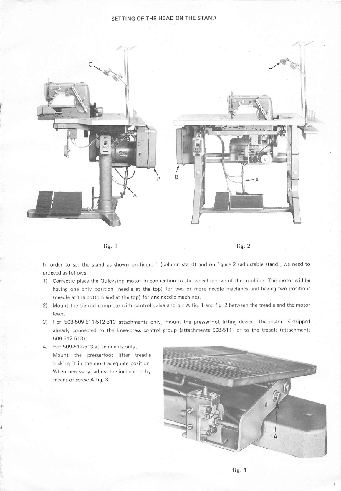
In order to set the stand as shown on figure 1 (column stand) and on figure 2 (adjustable stand), we need to
proceedasfollows;
1) Correctly place
having one only position (needle at
(needleatthe
2) Mount
the
bottom
tie rod
the
Quickstop
complete
motorinconnectiontothe
the
top)
for two or
andatthe
top)
for
one
needle
with control valve and pin A fig. 1 and fig. 2 between
wheel groove of
more
machines.
needle machines and having two positions
the
machine. The
the
motor
treadle and
the
will be
motor
3) For 508-509-511-512-513
already
509-512-513).
connected
to the knee-press control
attachments
only,
mount
group
the presserfoot lifting device.
(attachments
508-511) or to
the
The
piston is'shipped
treadle
(attachments
ifi
Page 4

5) For 508-511 attachments only For submerged adjustable stand mount the presserfoot lifting knee-press on
the
front
cross
brace
fig. 4.
For normal adjustable stand
mount
the knee-press on
the
table fig. 5
For column stand mount the knee-press on the head support fig. 6
6) For
513-514
attachments
only
Mount the stitch closing-up control knee-press following the procedure as per point 5.
7) Carry
out
the mounting of the presserfoot lifter piston fixing same with the relative screws
To the crossbrace supporting the machine for setting on adjustable stands or similar ones (fig. 7 submerged
edition)
To
the
(fig. 8
bracket
normal
fig. 9
edition).
for
settingoncolumn
stands.
8) Mount the control box B fig. 1 and 2 fixing it to the bobbin holder (column stand) or to the table (adjustable
Page 5

9)
Fixinthe
figure 10.
10)
Connect
the
air
rear
partofthe
Tighten
air.
Before
passage of air are
to
the
corresponding
the
various pins to
tubes.
For
connection
box
aretobe
well
the
locking
connecting
carefully
tubeisequipped
holeonthe
the
followed.
screwofthe
every
single pin
cleaned
with
the
table
box
taking
of
the
pins,
instructions
pinsinordertoavoid
make
and
that
seal ring, fig. 10.
pin A by
care
sure
every
meansofflange
nottobendorentangle
indicated
useless loss
that
the
orifices
single
connector
on
for
joined
B
the
of
the
Ik
fig.10
11) Place
the
belt
adjusting tension
Connect
12) Connect
13) Mount on
proportioned
entangled,aminor
•
The
adjustmentiscarried
head on
the
the
the
stand taking care
presserfoot
of same and
lifting
checking
pistontothe
pins joined to the control unit with
the
bobbin-holder shaft the
according to the
locking
type
of yarn used. A greater locking is required for yarns with
for
stable
yarns.
outbyactioniny
not
to damage
the
presserfoot
'C
thread lockings, fig. 1 and fig, 2, The thread locking will be
the
alignment.
the
talMe
above clamping element B fig. 16. Mounj
lifting lever by means of
the
fitted
adjustable
socket as per point 10.
tendency
lever A, fig.
11,
the
tie
to get
drive
rod.
Page 6
ADJUSTPyiEIMTS
TO BE CARRIED OUT BEFORE COIMNECTING ATTACHMENTS 507-508-509-510.511.512-513-514
TO
THE
COMPRESSED
AIR
LINE.
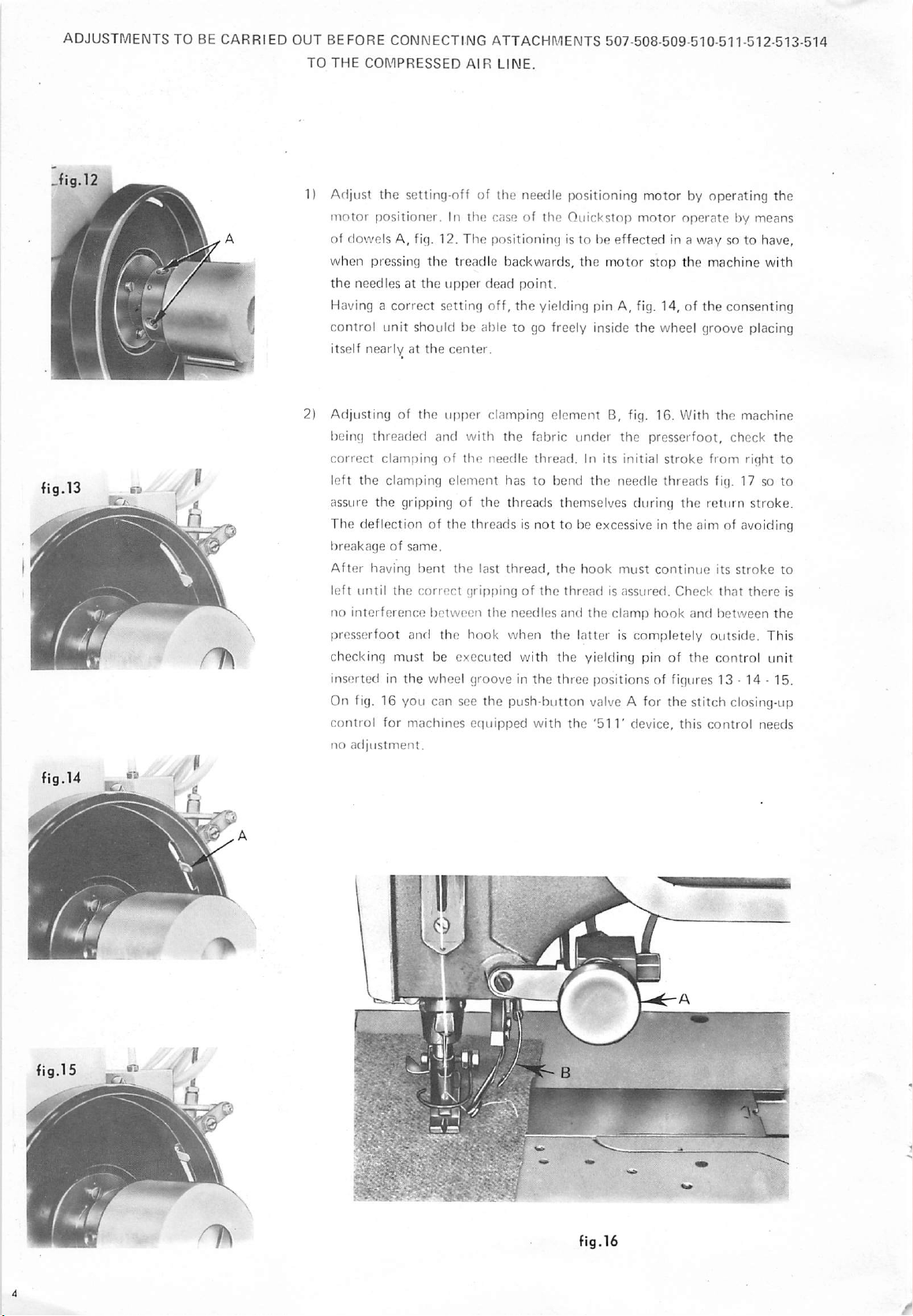
1) Adjust
motor
of
when
the
Having a
control
itself
2) Adjusting of
being
correct
left
assure
The deflection of the threads is
breakageofsame.
After
left
no
presserfoot
checking must be executed with
inserted in
the
setting-nff of the needle positioning
positioner.Inthe
dowels
A, fig. 12.
pressing
needles at
correct
unit
should be able to go freely inside
nearlyatthe
threaded
clamping of
the
clamping
the
gripping of
having
until
the
interference
and
the
case of
The
positioning
the
treadle
the
upper
dead
setting
off,
center.
the
upper
clamping
and
with
the
needle
element
the
bent
the
last
correct
grippingofthe
between
the
hook
the
wheel groove in
the
Quickstop
is to be
backwards,
the
motor
point.
the
yielding pin A, fig. 14, of
element
the
fabric
thread.
hastobend
threads
thread,
needles
when
themselves
not
to be excessive in the aim of avoiding
the
and
the
the
the
three
B, fig. 16. With
under
In its initial
the
hook
thread
is asstired.
the
latteriscompletely
yielding pin of
[jositions of figures 13 • 14 • 15.
motor
motor
effected
the
the
needle
during
must
clamp
by operating the
operatebymeans
in a
way
stop
the
machine
the
wheel groove placing
the
presserfoot,
stroke
from
threads
continue
hook
the
Check
and
fig. 17 so to
return
its
that
between
outside.
the
control unit
On fig. 16 you can see the push-button valve A for the stitch closing-up
control
no
for
adjustment.
machines
cciuipped
with
the
'511'
device, this
control
so to have,
with
consenting
machine
check
the
right
stroke.
stroke
there
the
This
needs
to
to
is
a «
iB-
-y
i X
fig.16
Page 7

In
order
to obtain
In
ordertoobtain
ordertoobtain
In
u
the
vertical displacement of
the
horizontal
the
correct
displacementofthe
positioningofthe
M
fig.17
the
clamping element
clamping
hook
in respect to
operate
element
the
on screws A fig. 18.
operate
threads
on screws B fig. 18.
operate
on dowel A fig. 19.
fig.18
fi9.19
Page 8

CONNECTION
OF
THE
ATTACHMENT
TO
THE
COMPRESSED
AIR
LINE
FIG.
20
1) Connect the attachment to
pressureofthe
attachmentis4,5
the
compressed air line or to the compressor. Check
• 5
Atm.
This
pressure is indicated by
the
that
manometer
the work
A.
Should the pressure be different from the one abovesaid, operate on screw B in order to get the pressure to
the
required
N.B. When necessary to diminuish
metal
2) Fill
lubricator
This
filling is carried
N.B. In order to fill
After
done
screw
At
least
The condensate level must never be exceeding metal ring I.
The
condensate
filter.
Once
washing and
the
filter by unscrewing
be
cleaned
Fig.20control
N.B.
the
'PRESSERFOOT
level.
ring'Cand
adjustment
'D'
up to
having completed
F, is of 1
G.
one
drop
a week
proceed
discharge is
every 6
months,
subsequent
with
gasolineorderivatives).
box
for
For
the
507-510-514
the
pressure, you should release first
screw
B.
the
indicated
out
removing screw E.
the
lubricator, it is necessary to disconnect the
the
testing of
every 30 •50complete
with
carried
proceed
with
blastofcompressed
the
knurled
508-509-511-512
attachments
LIFTER'
PRESSERFOOT
grip
maximum
the
machine, check
level
with
trimming cycles. Such an
the
condensate
discharge
outbyoperatingonpush-button
the
metal
with
LIFTER
cleaning of
and
the
the
the
sintered
air.
For
this
ring 0 fig.20(the
513
attachments.
control
relative
box
connections.
CONSENTING
the
air of the circuit and
oil VR
604
(ESSO
attachment
that
the
oil inflow, visible from
adjustment
which
gets
accumulated
A fig. 21 placedatthe
bronze
operation,
filter and
filter L fig. 20 by
it is necessary to disassemble
lubricator
fig. 20 will be lacking of
ATTACHMENT
then
STANDARD
TERESSO
from the compressed air line.
the
lubricator small
is obtained by operating on
inside filter H.
bottomofthe
meansofpetroleum
the
cups
'H'
and
'D'
the
components
TO
THE
R.T. and of
TREADLE
are
loosen
body
not
OR
43).
of
to
KNEE-PRESS
Page 9

1)
Adjustmentofthe
The
consenting
a) It permits
the
point);
in
the
wheel groove (fig. 23)
b)
with
allows
trimming
It is,
screw C (fig.
down;
The
machine
have to
quickly
Check
wheel is
adjustment.
ADJUSTMENTS
(It is advisable to remove the needles, before proceeding with the above adjustments).
machine
consenting
control
the
trimming cycle only when
with
unit
the
control
has a
needles in
only under these conditions,
wheel groove (fig. 14). If
the
trimming of threads
the
slow
exitofthe
the
machine
operation.
therefore,
22).
whilstbyturning
optimum
stopping
start
stop
it by pressing
that
the
not
running.
to
completely
necessarytoadjust
By
turning
the
speed is
the
yielding
when
time.Inordertocarry
machine
backwards
pin
The
return
TOBECARRIED
unit (fig.
double
function;
the
the
the
yielding pin does
piston
A (fig.
stop
the
piston
this
screw in,
screw
out,
the
exit
gettingitto
the
gets
into
speed is very high
OUT
WITH
22).
the
motor
has stopped
upper
part
(upper
dead
yielding pin A fig. 22 fits
not
fit in the
cannot
take
place.
23),
the
control
before
the
time
out
the
treadle.
the
effecting
exitbyoperating
the
piston
pistonisaccelerated.
coincidestothe
this
adjustment,
rating
loop
only
and
is slowed
speed
when
needs no
unit
the
you
and
the
ATTACHMENT
on
UNDER
PRESSURE
fig.22
2)
Adjustmentofthe
The
valve
function:
a) by pressing forth the treadle to
created
b) by pressing backwards
unit,
the
trimming
c) it does not permit the repeating of the cutting
of
at
necessary
unthreading.
adjusted
minor
of
getting
essential
machine
By
loosening
unscrewing or screwing
necessary to
valve
adjustment
I) press
II)
forth
executing
the
treadle,acomplete
If
this
excessive stress and it is,
(fig.
24).
push
forth
having
backwards no cutting cycle should
occur,itmeans
therefore,
The
balance
several
valve
mountedonthe
mounted
and same charges bag P fig.20containedinthe
cycleisreleased.
air
on
the
contained
motor
the
treadle,
in bag P fig. 20
tie rod (fig. 24)
actioning
start
the machine, an air passage is
after
the
consent of
tie
which
rod
cycle"
least a few
to
accordingtothe
resistance
the
that
has
startedtosew.
nut
operate
the
about
cycle
the
the
machine
necessary to
trials.
stitches
avoid
the
This
valve, in
opposed
perfect
the
valve charges bag P (fig. 20)
A (fig.
shaft
valve fig.24is increased or
and
control,
treadle
ten
stitches:bypressing
does
not
treadle
run.
that
the
between
point
has
taken
dangerofthe
ordertoperform
typeofsetting
by
the
motor
performance
24)
on
side
guiding bushing B (fig.
you
should
having
cutting
occur,itmeans
without,
screw
the
cycle
therefore,
By,
subsequently,
valve
requiresatoo
bushing B (fig.
I) and
however, reaching
point
place.
This
needles
clucth.Infact,inthe
of
with
proceed
machine
subsequently
oughttotake
that
necessary to loosen bushing B
take
place. Should this cycle
II) is to be
and
function
andtothe
the
attachment,
only
numbers
24),
diminuished.
as follows:
started
place.
the
valve
pressing
little
24).
has a
triple
box.
the
control
controls
unless a seam
condition
the
looper
C, istobe
greater
when
6-1
and
the
stress
For
slowly
backwards
requires
the
stage of
the
treadle
stress
and
found
through
the
is
or
aim
it is
the
by
the
^nd
an
it is,
1"^
fig.23
/
Xa
fig.24
Page 10

CUTTING
STAGES
I)
Correct
cutting
Needle
positioningofthe
cycle:
above—Looper
fe)
A^ 1I
needle
totallyonthe
flg.25
andofthe
left
looper
so as to
permit
the
II)
Exitofthe
the
the
accomplishareduced
Rotationofthe
central knife (A) which passes through
needle
thread
counter-knifeBandofthe
wound
upper
stroke.
clamp
around
hook
fig.26
the
lower
D
looper.
clamping
the
Contemporaneous
loop formed by
elementCwhich
exit
of
III)
Returnofthe
thread.
Delayed
thread
returnofthe
above
the
central
needle
knife
superior
plate.
that
clamp
hooks
the
hookDwhich
looper
and
grips
the
the
needle
needle
IV)
Clamping
the
Taking over of the needle thread and clamping of same above the
needle
of the looper thread below the needle plate and return of
three
knives A B C to
plateonthe
side of
the
rest position.
clamp
D.
/
Page 11

ADJUSTMENTS
PRESSURE
TO
AND
BE
WITH
CARRIED
THE
OUT
WITH
MACHINE
ATTACHMENT
BEING
THREADED.
UNDER
1) Setting-off and threading of
enclosed to
2)
Adjust
3)
For
the
machine. A precise setting-off is
the
stitch
length
510-511-512-513-514
closing-up in such a way so to avoidthe undoingof the
According to
closing-up.
4)
Adjustment
25-26-27-28).
In
the
necessarytoverify
small
threadofthe
a)
cut
the
seam exigencies, never exceed in the stitch " "
and setting-off of
aimofobtainingaperfect
that,
knife
A (fig. 26) goes
needleorof
out
the
compressed
the
machine. Carefully follow the setting-off and threading instruction sheets
whichisrequired
attachments
the
thread
during
the
cutting
into
the
the
needles
air
line
from
the
guarantee of a good performance and of a perfect seam.
during
the
seam.
adjust
the
stitch
seam.
trimming knives (fig.
trimming,itis
stage,
the
central
loop
formed
woundonthe
the
circuit.Inorder
by
the
looper.
to cut out the compressed air from the circuit it is p
(508-511
b)
executeaseamof4-5
c) check, by hand operating on the piston shaft,
needle
position
with
N.B. This setting-off can be carried
stress
5) Adjustment of the needle thread enriching cylinder (fig. 30).
In
the
the
right
lower
the cylinder by operating on
In the
the
seam
attachments).
thread
wound
the
knives block (fig. 29) loosening
closed-up
will be
neededtoget
caseinwhich
side
of the
caseinwhich
after
the
stitch
there
seam
there
cutting
crn.
on
the
looper.
for
510-511-512-51
the
shouldbean
executed
should
cycle
with
Should
3-514
out
also with
trimming
knife
excessofthread
afterthe
screwsA(fig.
be an
irregular
slip
stitching,
that
the
the
attachments.
out
cutting
30).
starting
the central knife goes perfectly in the loop of the
mentioned
2 screws A (fig.
the
being
on v J ^
cycle,
lift
the
_
^
^
'
r-'
Tig.29
fig.29
condition
attachment
the
small
of I
failtooccur,
29).
Repeat
under
pressure. In this case, a greater
piston
under
shifttothe
the
abovesaid setting-up
pressure.
M
,««—
'
J
tn
correct
y*
'
N.B.
By
lifting
needle
sameisdiminuished.
6)
Adjustmentofthe
enriching
adjustmentiscarried
stroke-limiter
greater
in
the
The
by
threadisincreased
initial
order
to
beginningofthe
shiftingofthe
operatingonscrews
the
cylinder
strokeofthe
small
avoid
piston
out
A,
whenever
enrichmentofthe
the
lossofsome
seam.
stroke-limiterisobtained
B.
(fig.
30),
the
enrichmentofthe
whilstbylowering
looper
thread
(fig.
31).
This
through
necessarytohave
shifting
looper
stitches
thread,
fig.31
^
the
cylinder,
of
a
at
fig.
J
30
Page 12

7)
Adjustment
Should
sufficient or
perfectly
screws
of the
the
tension
automatic opening of
viceversa,
closed,
A.
lift or
opening
small
the
piston
(fig.
tensions be
should the tensions fail to get
lower
the cylinder by operating on
32).
not
rr!rii
8) Stitch closing-up group
attachments
This group is to be adjusted only when varying the degree of
closing-up of the stitch and the stitch length.
In
case
C.With a clockwise rotation the stitch closing-up ratio is diminuished whilst with a counterclockwise rotation
sameisincreased.
only.
of modification in the
(fig.
33) for 510-511-512-51 3-514 ^ig. 32
degree
of the stitch
closing-up
loosen
screw
S
Bandrotate of
some
degrees
lever
fig.
33
iO
Page 13

PNEUMATIC
SKETCH
®
OF
(3)
THREAD
(D
CUTTING
ATTACHMENT
507
®
d)
© (D (I)
I —
group
made
up of
5—2
6 —
8 — 4
9 —
10 —
II
— 4
13
—
A —
B —
C —
D —
E —
ways valve
Impulse
ways
valve
adjustable
thread
trimming
ways
piston
Attachment
tension
needle
threads
knife
controlling
looper
enrichment
needle
threads
controlled
bag P fig.
controlledbya
delaying
valve
small
opening
enriching
clamping
filter-reducer-manometer-lubricator
by a
treadle
(with
20
valve
operation
controlling
pistons
piston
piston
piston
treadle
C fig.
2^
consenting
spring impulse S fig.
fig.
32
piston
fig.
fig.
29
fig. 31
piston
fig. 16
(with
device
30
traction)
compression)
fig.
fig.
20
fig, 24 side 6-1
fig. 24
22-23
20
side
3-4
11
Page 14

PNEUMATIC
SKETCH
OR
OF
THREAD
AUTOMATIC
CUTTING
ATTACHMENT
PRESSERFOOT
®
LIFTER
®(9)
WITH
508-509
PNEUMATIC
HAND
® (i) ©
(2)
©
3 —
group
made
up of
4 — 4
5 —
6 —
7—2
8 —
9—4
10 —
11 —
ways
piston
presserfoot
commutator
ways
valve
impulse
bag P fig.
ways
valve
adjustable
thread
trimming
filter-reducer-manometer-lubricator
valve
controlling
lifting
cylinder
valve T fig.
controlled
20
controlled
delaying valve C fig.
operation
12 — 3 ways valve controlled by air for the
13 — 4
15 —
A —
B —
C — knives
D —
E — needle
ways
piston
attachment
tension
needle
threads
controlling
looper
thread
threads
valve
controlling
small
opening
pistons
piston
enrichment
piston
enrichment
clamping piston fig. 16
fig. 7-8-9
20
by a
treadle
by a
treadle
22
consenting
spring'S'impulse
fig.
32
piston
fig. 29
piston fig. 31
the
presserfoot
fig.
(with
traction)
(with
compression)
device fig.
automatic
30
fig.
lifter
22-23
20
fig. 3-4-5-6
fig. 24
side
fig. 24 side 3-4
6-1
actioning of the presserfoot lifter cylinder
fig.
20
12
Page 15

PNEUMATIC
SKETCH
FOR
THREAD
CUTTING
ATTACHMENTS
CLOSING-UP
510-514
WITH
PNEUMATICALLY
CONTROLLED
STITCH
® ®
(D
® (i) © ® ©
s,
I —
5—2
6 —
8—4
9 —
10 — thread cuttingoperationconsenting
II
13 —
A — tension
B — needle
C — knives
D —
E —
14
15 — 3
j
✓
— 4
—
group
made
ways
valve
impulse
ways
valve
adjustable
ways
piston
attachment
opening
threads
controlling
looper
thread
needle
threads
stitch
closing-up
ways
valve
up of
filter-reducer-manometer-lubricator
controlled
bag fig.20part
controlled
delaying
valve
small
pistons
piston fig.
enrichment
piston
enrichment
clamping
controlling
controlling
valve fig.
controlling
by a
P
by a
fig.
piston
piston
the
treadle
treadle
22,
32
piston
29
piston
stitch
part
spring
fig.
fig. 31
fig.
16
fig.
closing-up
(with
(with
C
device
impulse
30
33
traction)
compression)
fig.
22-23
fig.
piston
fig.
20,
fig.16or
fig.
24
part
fig.
20
S
24
figures
4-5-6
13
Page 16

PNEUMATIC
SKETCH
PRESSERFOOT LIFTER
FOR
THREAD
WITH
CUTTING
ATTACHMENTS
PNEUMATICALLY
CONTROLLED
0
®@
WITH
HANDORAUTOMATIC
STITCH
CLOSING-UP 511-512-513
PNEUMATIC
©00
1 — stitch closing up control piston
2 — 3 ways valve controlling
the
stitch closing up piston
3 — group made up of filter-reducer-manometer-lubricator (see fig. 20)
4—4
5 —
6 7 — 2
8 —
9—4
10
11 —
12—3
13 — 4
15 —
A —
B —
C —
D —
E —
ways piston valve controlling
presserfoot
commutator
impulse
—
adjustable
thread
attachment
tension
needle
knives
looper
needle
ways
ways
ways
ways
lifter
valve T fig.
valve
controlledbya
bag
P, fig.
valve
controlled
delaying
trimming
valve
controlled
piston
valve
small
opening
threads
enrichment
thread
enrichment
threads
enrichment
clamping
cylinder
20
valve C fig.
operation
controlling
pistons
piston
piston
fig.
20
by a
by air
fig.
piston
fig.
piston
piston
the
presserfoot lifter (see fig. 3-4-5-6)
7-8-9
treadle
(with
traction)
treadle
(with
the
fig.
compression)
device
automatic
impulse
30
fig.
22-23
actioningofthe
S fig.
22
consenting
for
spring
32
29
fig. 31
fig. 16
see
26
fig.
24
see fig. 24
presserfoot
lifter
cylinder
\4
Page 17

STAMPATO
A
CURA
NELLE
DELL'UFF,
OFF.
RIMOLOl
CATAL06HI
Page 18

SEDE
! 1* ^
D!
MILANO
S.p.A.
STABILIMENTO
VIRGINIO
RIMOLDI
D1
OLCELLA
&
C.
VIA
VESPRI
TEIEF
470.152/153/154/155
TElLGRAMMI
SICILIAN!,
VIRIMOLOI
9 -
-
-
MILANO
479.558
MILANO
PrintedInItal;
 Loading...