

Page 1
RLnUTLdL
IL-I
SPARE
PARTS
HEAD
AND
HEAD
CATALOGUE
228•0001
SUBCLASSES
2282BD5
33/A
N.
CAT.
652230400
of
20/68
Page 2
INTRODUCTION
IDENTIFICATION
HEAD
I
-
II
-
TECHNICALDATAOFCLASS
TECHNICALDATAOFSUB-CLASSES
III
INSTRUCTIONS
INDEX
Pag.
5
5
6
INSTALLATION
I
-
-
Positioning
a
b-Transmission
c-Lubrication
d-Assembling
-
Adjusting
e
•
Setting
-
Needle
g
h-Electric
II
front
thread take-up
lubrication
-USE
a-Threading
b-Changing
c-Setting
d-Setting
e
-
Stitch
f
-
Seam
-
Problems due
g
III
-
Every
a
-
Every
b
-
Every
c
the
of
length
width
-
MAINTENANCE
day
week
three
d-Sharpening
head
of
assembly
and
Adjusting
locking
and
cover
the
needle
presserfoot
tensioning
adjustment
adjustment
to
months
the
knives
presserfoot
plate
adjustment
control
discs
improper
AND
Sewing
device
handling
SETTING
Parts
arm
of
UP
machine
Pag.
11
11
11
-
11
11
16
16
16
17
19
19
23
23
23
23
23
24
25
25
25
25
‘
25
PARTS
CATALOGUE
I
-
Introduction
a
II
•
HOW
TO
-
HOWTOORDER
USE
SPARE
THIS
a-Allparts
-
Needles
b
-
TABLES
III
PARTS
IV
NUMERICAL
INDEX
OF
CATALOGUE
29
29
29
29
31
79
Page 3

INTRODUCTION
Page 4
I.
HEAD
IDENTIFICATION
1
2.
3.
Identification
a)
Every
—
class and
—
serial
he
class
ihe
head
head
number
is
sutjclass
and
serial
numbers
identified
sub-class
number
by:
numbers
numbers
is
engravedona
are
engraved
boss
on
on
the
the
nameplate
bottom
on
the
base
of
the
base.
the
of
machine.
ihe
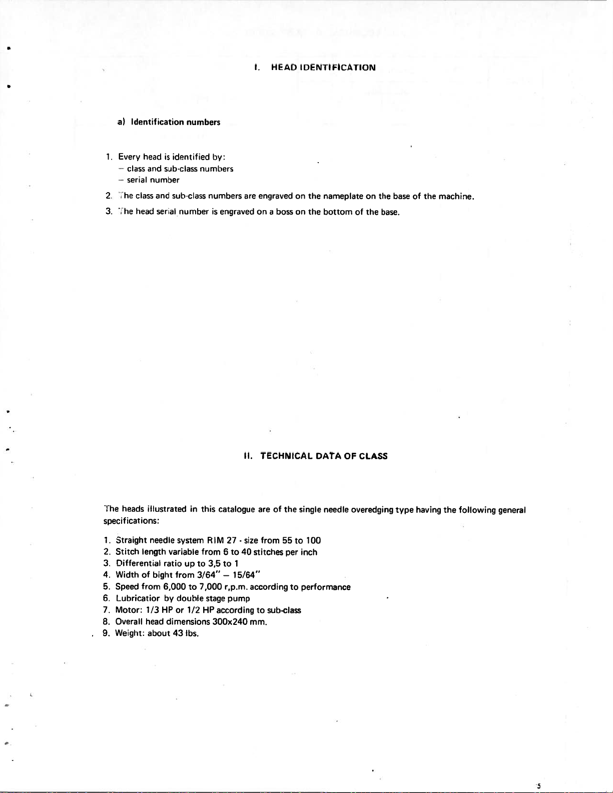
heads
specifications:
Straight
1.
Stitch
2.
3.
4.
5.
6.
7.
8.
9.
length
Differential
Width
of
from
Speed
Lubricatior
Motor:
Overall
Weight:
illustrated
needle
variable
ratio
bight
6,000
by
HP
1/3
dimensions
head
about
system
up
from
double
or
43
to
1/2
lbs.
in
this
RIM
from
to
3,5
3/64”
7,000
stage
HP
catalogue
27
6to40
to
—
15/64”
r,p.m.
pump
according
300x240
II.
-
size
1
TECHNICAL
are of
from
stitches
according
to
sub-class
mm.
55
the
to
per
to
DATA
single
needle
100
inch
performance
CLASS
OF
overedging
type
having
the
following
general
5
Page 5
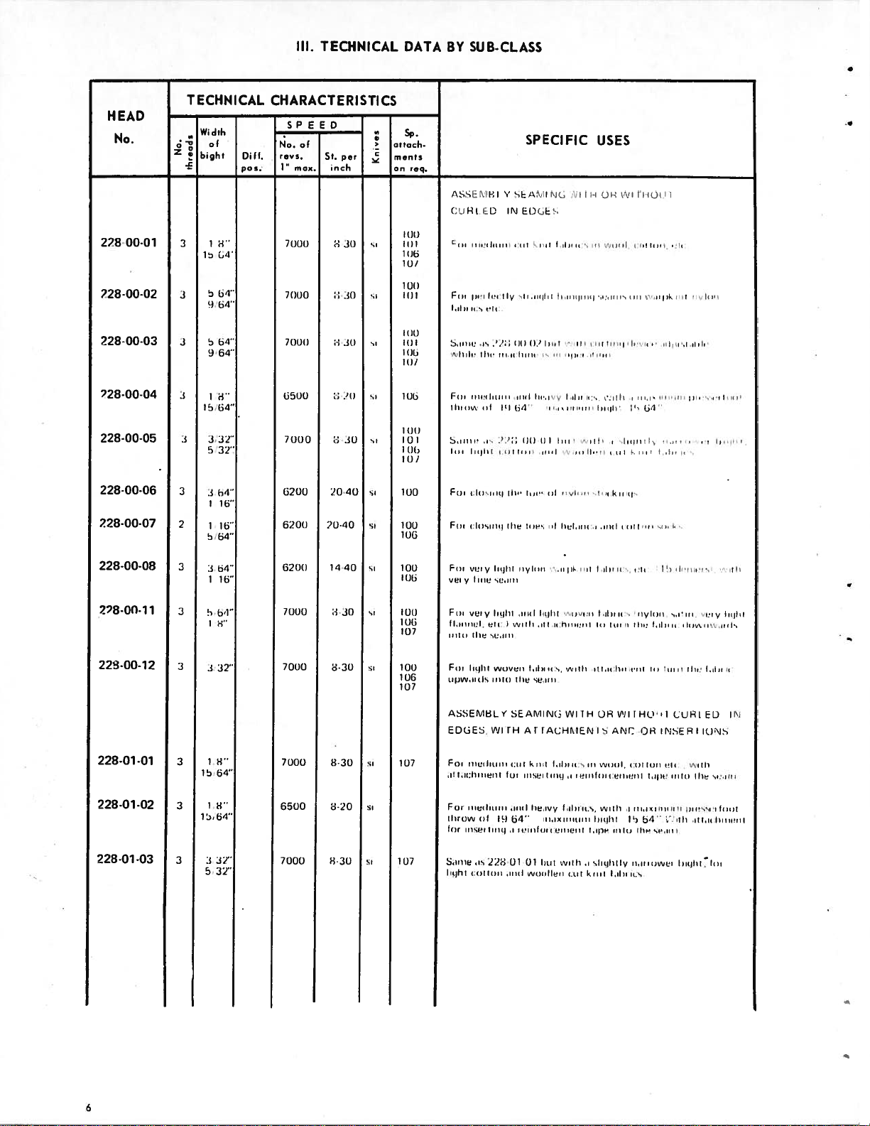
III.
TECHNICAL
DATA
BY
SUB-CLASS
HEAD
No.
228
00-01
228-00.02
228-00-03
228-00-04
228-00-05
228-00-06
228-00-07
TECHNICAL
———
Wdth
of
0
Z
bight
&
15
n’)
(14”
5
1)
64”
134”
5
3
04”
1)
3
H”
T5,64”
3,32”
3
5
32”
3
04”
3
1
16”
7
1
16”
64”
5
CHARACTERISTICS
SPEED
N0.
of
revs.
D1If.
pos.
I’
m
ax.
71101)
it
1(1(1
71)1)11
3500
7000
6200
1320))
St.
i
20-40
20-40
—
‘•
per
n
ch
attach.
ments
on
req.
/\s;Eft’IH)
(
HI
EDINEOUC
11)11
II
1(1)3
111/
3(1
1(T))
sc
TI))
Ill))
ITT
TI))
I
11/
si
Ill_i
(It)
su
TI)
Ill,
III
1
si
(JO
sc
100
TOO
Eric
—i_rcrr
‘,‘‘lrrIiltirnru,iuhrurnr-isnr
Fun
ilirui_,’
I
Si_in’
/
Fur
Fri
(i_cr
ui_i
Ii,’,
,i_’,
,iiicrlirr,cn
Iri(Irliniiiurninrnul
Ju’rrnq
r,Iiisi_nnij
Iii
it
is
Tt
‘20
V
ly
nini_,
Fc\iIN11
Ill
i_ri_i_I
lii’
tin’
SPECIFIC
iri_cijIrl
Ir.rcirjirui_
iii
0.)
‘‘nh
iC)(ii’I
hnr•,u’
y
ri,
uinrn’
1))
II
ui_i_i
liii”
ri_I
rrvliinr
(un,’’
nit
trrcl,urni
USES
I))
iVIlIl
‘i_i_iris
i_Ill
r’,irlikrrit
i_i_i_ni,
liii
,ui
Inn
un’s
u’nflr
sins
Iuijti:
,i_
I’’
1,.)’’
,i_
sliuhinI
5
kim1-,
inn
rut
iii
pinlir
,uunlti’n,i_i_uii’,tu,it,iluuu’,
rivlrrrr
nr,unnni_’,’r
228-00-08
228-00-1
228-00-12
228-01-01
228-01-02
228-01-03
3
b4”
3
1
16”
1
3
3
32”
1
H”
3
15
64”
1
H”
3
1564”
32”
3
3
5
32”
6200
71)00
7000
7000
6500
7000
1440
3-30
3-30
H
5-20
i-i
Fur
sPry
InuTti
si
I
01)
I
1)6
si_
(1111
1)13
07
si
IOU
011
07
very
ti_mu
Fur
very
)I,inniriil,
ii
liii
I
Fir,
tight
ui(Ji_’Ji_rilsrnitii
ASSEFIUL
EDOES,
Fit
30
30
107
Sn
Sr
Si
1
07
r
ri_ic
,,tt,i_pttinrpnnt
For
rnrenlrii,nn
utiiui_w
icr
rni_srertrnri,irnci_rilrini-ecnrr’nri
Sin_c
(gIrt
r,rittirnr
semi,
Iii)hi_l
ccli:
liii
icc
‘cc
woven
y
VYITHATI
liii
ni_n
li_c,
ni_I
19
is
221-JUT
isO
rnytirnn
‘.‘
unit
lujiul
u’jrtlr
,i_ii,uu.hriiinmn
ti_Icr
liii
se,irnr
SEAMINC
ACHFILNISAND
k
ri
it
cii
trmrc(
ri_si_in
i_ni_il
tre,uvy
nnr,rxi_irrni_nnr
(14’’
UT
li_i_il
wi_nIle,
,ir1il
‘rivitnr
is,
vvnttr
WITHOH
I
ti_inc
p
ti_hr
with
i_i_ct
nut
liii,
ii
iii,
i_’5
ii,
turin
-itl,ri.tnrr,r’,nt
Eli
,vjui_ii
ri_n
ri_s.
,i
knit
ti_(Dre
slightly
untO
(Itt
t,ihi_r
I
Hill,
,ilrnrhiirr.r,rrru,’cu
,,
i:in
niylniri,
liii,
HOn
I
OR
iii
trill
t,i_)in’
nnr,rurrrrrnr’m
p
Ti
i_i4’’,’:utr
lip
nr,i_i_ruwnr
ri_s
Tb
ilium
ri
‘urn
iT
INSER
p
sr’,nnri
Iii
su’uni,
nIiirmrc,,nrnIs
iii’
CUR)
I
cv
run
r
stun
ttni
,irrm’,sr’rtui_ui_)
,utt,ii.Irrrrflrnt
ri_glut.
‘my
EL)
IONS
(irjtnn
IN
si_li_rn
iii
a
Page 6
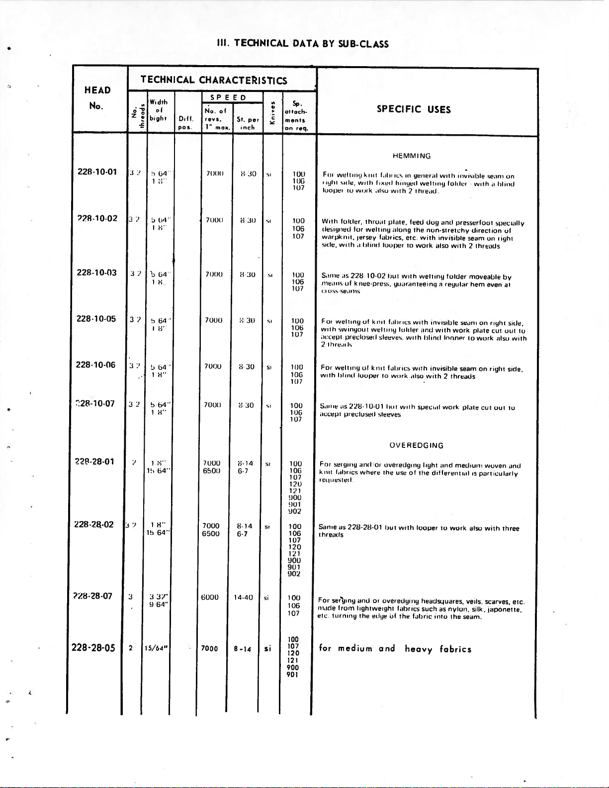
III.
TECHNICAL
DATA
BY
SUB-CLASS
HEAD
No,
228-10-01
728—10-02
228-10-03
228-10—05
228-10-06
TECHNICAL
———
Width
Z
bight
‘±
.
J
,i
tn’l’’
.‘
,
1
;-
3
7
64’’
1
3 7
04’
‘‘
1
CHARACTERISTICS
SPEED
D1!l,
reos.
p05.
1
moe.
ill(S)
7000
/(1(1(1
7000
—
St.
SPECIFIC
per
rich
-1
30
8
30
on
req.
HEM
si
10(1
101
si
lug
106
107
si
100
100
1(11
si
100
lOIn
1(17
1(11)
106
10!
Fur
in(lnt
looper
Viiilfr
Iusignur,’d
svirpk
smufc’,
Srurrw
rununis
(isS
Fun
will,
nn’cepi
iOn
2
For
with
vr’Ilrrirr
sine,
u.n
folder,
rr
with
is
of
seuntis
s’e0rrrq
swinqonit
precliuseil
Sun’,
well
blind
with
wnirk
for
II
(ersey
lnlinnnl
i
228
kiree-pruss,
of
eug
of
looper
knit
tlironl
well
10-02
fun
,ulsu
mug
filur
knit
welluurr
1
sleeves,
knit
us
veil
fnrnnn(enl
with
tIltS,
dung
cs,
lool)liitovvoi
but
ilunimnnlteeing
f,i0nicswith
fil
to
work
M
ri
1’
feed
etc
with
funldni’
with
us
N
gruuurr,uI
welunir
1
tlrre,nn(
the
with
welling
rind
with
ilso
USES
(3
dog
non-st
k
invisible
lnlinnl
invisible
with
ssitlr
eurO
invisible
ilso
in
r
with
(runner
2
loluIi
presserfoot
retchy
with
folder
eqolrur
work
thrennis
unrvrsuble
will,
direct
seem
lhrn,rinls
2
moverible
hem
seurli
pinte
to
seam
or
work
on
sennru
i
specinllv
on
or,
even
righi
cut
right
fnlnrrrl
of
right
by
et
out
elso
on
side,
side,
with
to
‘28-10-07
22-28-01
228-2a-02
228-28-05
3
j:’10’
2
7
1,4’’
5
li-I’’
1
15
lb
.1
1)
15/64”
0’’
64’’
64’’
37”
64”
70011
7000
65011
7000
6501)
6000
7000
6-7
8.14
6-7
1440
8-14
1-14
s
100
Smnri
ms
106
107
si
100
106
10/
(1(10
101
002
100
,
000
001
002
Si
100
106
107
100
si
121
900
901
106
107
120
11’
Snow
t
1
For
made
etc.
for
iccept
For
sei
knit
fibi
i5ulmiesleil
hretcis
set’ging
tuurr’uirug
72810-01
pree(oser(
gong
us
‘is
720-28-01
from
medium
sleeves
uuf
oi
wl’iere
rind
or
lightweight
the
edge
hut
with
OVEREDGING
oveiedgii,y
the
use
but
with
overedyniug
fabrics
of
the
and
specuil
of
the
looper
fabric
heovy
work
light
end
clitfereirt
to
herudsqutres,
such
as
unto
fabrics
medium
work
nylon,
the
plmile
nil
jIso
eels.
serum.
is
silk,
cot
woven
pert
with
scarves,
out
icularly
three
ruponette,
to
unrj
etc.
Page 7

0
III
-I
z>n
—c
un
Z>O
ZO..
m
Az-n
Z
-I
—
z
Q
I
Page 8
1
2.
1.
2.
3.
4.
5.
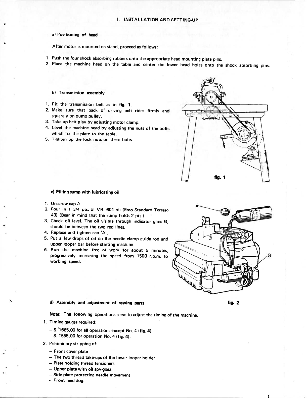
Positioning
a)
After
Push
the
Place
Transmission
hI
Fit
the
Make
squarely
Take-up
Level
which
Tighten
motor
four shock
the
machine
transmission
sure
on
pump
belt
the
machine
fix
the
the
up
of
is
mounted
that
play
plate
head
assembly
back
pulley.
by
head
to
lock
on
absorbing
head
on
belt
of
adjusting
by
the
nus
on
stand,
rubbers
the
as
in
driving
motor
adjusting
table.
these
I.
proceed
table
fig.
bolts.
INS
1.
belt
clamp.
the
onto
LLATON
as
the
and
rides
nuts
follows:
appropriate
center
firmly
of
the
£kNDSErTNG-UP
mounting
head
lower
the
head
and
bolts
holes
plate
onto
pins.
the
shock
absorbing
pins.
c)
Unscrew
1.
Pour
2.
431
3.
Check
should
4.
Replace
5.
Put
upper
Run
6.
progressively
working
dl
Note:
Timing
1.
—
S.
—
S.
Preliminary
2.
—
—
The
—
—
—
Side
-
illing
in
(Bear
a
few
looper
the
Assembly
The
‘1665.00
1555.00
Front
rvvo
Plate
Upper
plate
Front
sump
cap
3/4
1
in
level.
oil
between
he
and
drops
machine
speed.
gauges
cover
thread
holding
plate
feed
with
A.
pts.
rriincl
The
tighten
of
before
bar
increasing
and
following
required:
for
all
for
operation
stripping
plate
take-ups
thread
with
protecting
dog.
lunricating
of
VR.
that
the
visible
oil
the
two
IA’.
cap
oil
on
starting
free
the
adjustment
operations
operations
of:
tensioners
oil
spy-glass
needle
of
of
604
sump
red
the
No.
the
oil
oil
(Esso
holds
through
lines.
needle
machine.
work
for
speed
sewing
of
serve
except
4
(fig.
lower
movement
clamp
from
to
No.
4).
Standard
2
pts.)
indicator
about
parts
adjust
4
looper
guide
1500
(fig.
5
the
4)
holder
Teresso
glass
rod
minutes,
r.p.m.
timing
and
G,
to
fig.
I
fig.
2
of
the
machine.
Page 9
Positioning
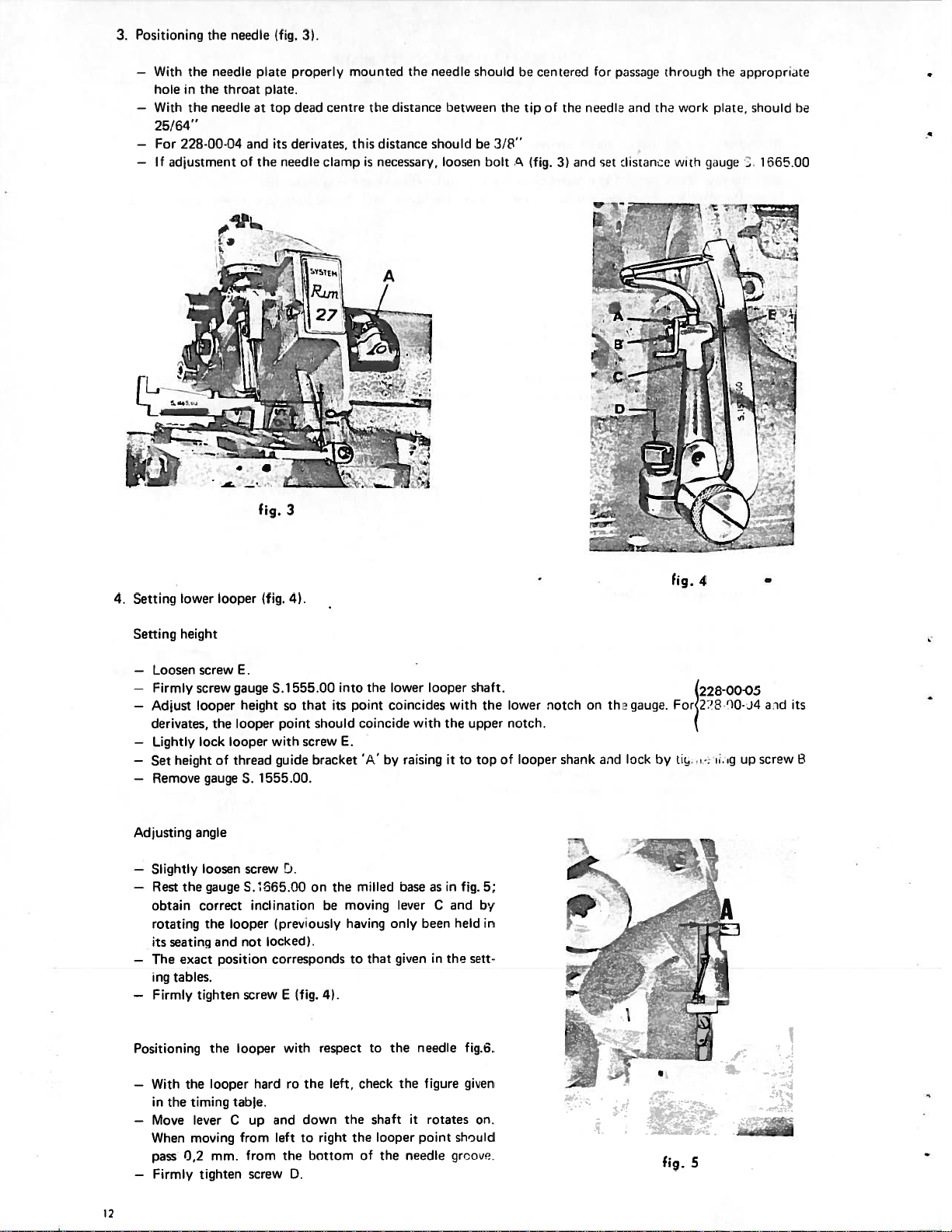
3.
—
—
—
—
With
the
holeinthe
With
the
25/64’
For
228-00-04
If
adjustment
the
needle
throat
needle
needle
and
of
(fig.
plate
properly mounted
plate.
dead
at
top
derivates,
its
needle
the
3)
centre
clamp
this
is
the
distance
distance
necessary,
the needle
between
should
loosen
should
he
bolt
the
3/8”
he
tered
for
and
riinella
sat
pis.,gothioiigh
and the
distiuw
work
with
the
ippi
pl;ite,
should
gauge.1
opriate
be
d6500
con
tip
of the
A
(fig.
3)
4.
Setting
Setting
—
—
—
—
—
—
Adjusting
—
—
—
—
lower
height
Loosen
screw
Firmly screw
Adjust
looper
derivates, the
Lightly lock
heightofthread
Set
Remove
gaugeS.1555.00.
angle
Slightly
Rest
obtain
rotating
its
The
ing
Firmly
loosen
the
gaugeS.1365.00
correct
the
seating and
exact
tables.
tighten
looper
E.
gauge
height
looper
looper with
screw
inclination
looper
not
position
screw
fig.
3
(fig.
4).
S.1555.00
so
point
guide
1).
(previously
locked).
corresponds
E
into
the
that
its
point
should coincide with
screw
E.
be
the
moving
‘/‘
milled
by
bracket
on
having
that
to
(fig.
4).
lower
looper
coincides
raisingitto
baseasin
leverCand
only
been
giveninthe
with
the
upper
fig. 5;
held
sett
shaft.
the
top
by
in
lower
notch.
of
looper
notch
shank
on
th gauge.
a-id
lock
fig.4
228-00-05
2310-j4
For
by
ic
.
aid
its
screw
up
.g
B
and
left
with
the
D.
respect
down
to right
bottom
Positioning
—
With
the looper
in
the
timing
—
Move
When
0,2
pass
—
Firmly
12
looper
the
table.
leverCup
moving
from
mm.
tighten
hardrothe
from
screw
left,
the
check
the
of
to
shaft
looper
the
the
the
it
needle
needle
figure
rotates
point
fig.6.
given
on.
should
groove.
.
5
Page 10
i’
III
I1(J
5
)er
Li
100
1)1
per.
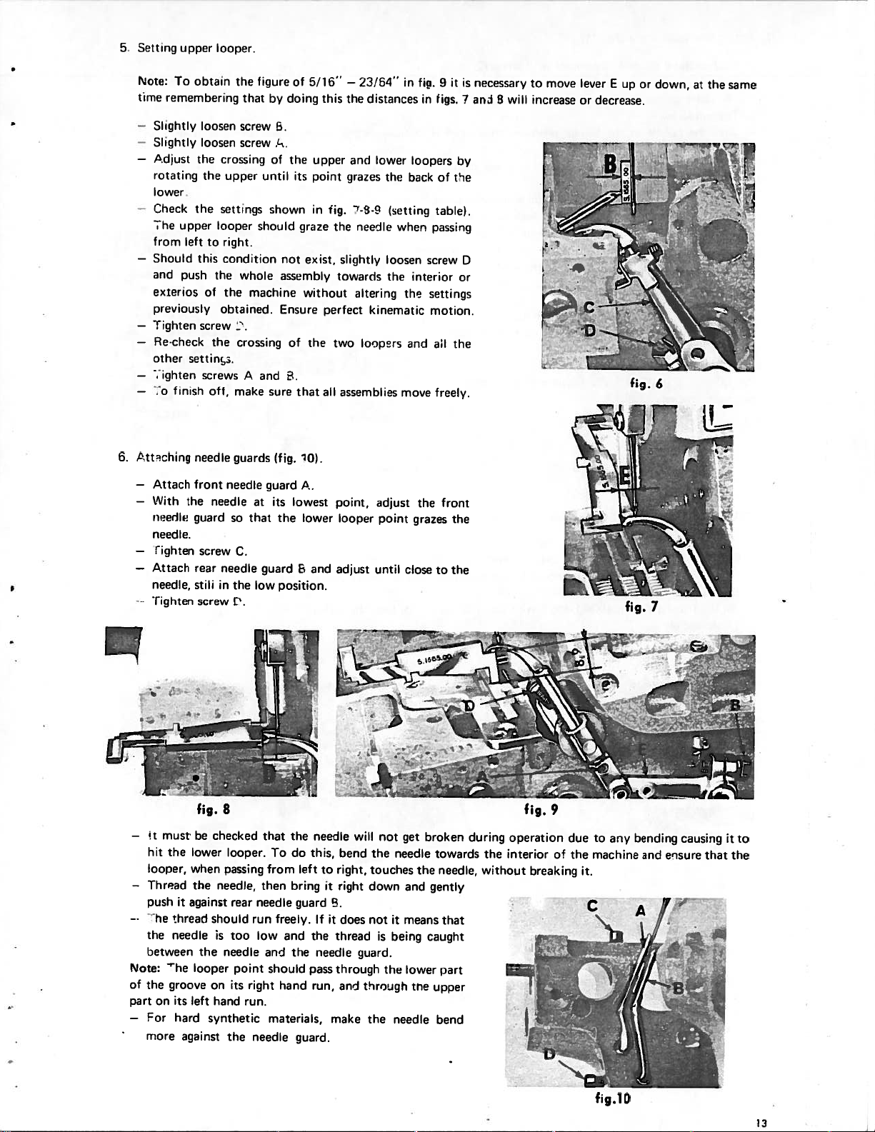
6.
Note:
time
—
Slightly
—
Slightly
—
Adlust
rotating
lower
-
Check
The
from
—
Should
and
exterios
previously
—
fighten
—
Re-check
other
—
lighten
—
.0
Attching
—
Attach
—
With
needle
needle.
—
ighten
—
Attach
needle,
Tighten
obtain
To
remembering
loosen
loosen
the
the
the
upper
left
to
this
push
the
of
screw
the
settin.
screws
off,
finish
needle
front
the
needle
guard
screw
rear
stili
screw
the
that
screw
screw
crossing
upper
settings
looper
right.
condition
whole
the
obtained.
crossing
A
make
guards
needle
so
C.
needle
in
the
t.
figure
by
b.
/-.
of
until
shown
should
machine
and
sure
(fig.
guard
its
at
that
the
guard
low
of
doing
the
its
graze
not
exist,
assembly
without
Ensure
of
.
that
‘O(.
A.
lowest
lower
E
position.
5/16’
this
upper
point
in
the
and
fig.
the
slightly
towarris
perfect
two
all
assemblies
point,
looper
adjust
—23/54”
the
distances
and
grazes
7-S-s
needle
altering
kinematic
ioopsrs
lower
thc
(setting
loosen
the
adjust
point
until
in
back
when
the
and
move
close
fig.
in
loopers
tahle(.
passing
screw
interior
settings
motion.
all
freely.
the
grazes
to
9
figs.
of
front
it
by
t1e
or
the
the
the
is
necessary
ani
D
move
to
8
will
increase
lever
or
‘T
E
decrease.
B
_ii_
ri
up
or
down,
at
the
same
‘k-1j
I
i—
fig.
8
must
—
—
Note:
of
part
—
‘t
hit
looper,
Thread
oush
the
between
the
For
more
he
on
the
it
thread
needle
The
groove
its
hard
against
be
lower
when
the
against
the
looper
on its
left
synthetic
checked
looper.
oass’rig
needle,
rear
should
is
too
needle
point
hand
the
run
right
run.
needle
that
To
from
then
needle
freely.
low
and
should
hand
materials,
the
bring
and
do
left
guard
the
guard.
needle
this,
to
it
If
the
needle
pass
run,
bend
right,
right
.
it
does
thread
through
and
make
will
touches
down
not
guard.
through
the
the
not
is
it
being
the
needle
get
needle
and
means
lower
the
broken
the
caug-it
towards
needle,
gently
that
part
upper
bend
during
without
the
fig.
operation
interior
breaking
9
of
-izJ’
due
to
the
machine
it.
C
\
any
bending
and
causing
ensure
that
it
to
the
t3
Page 11
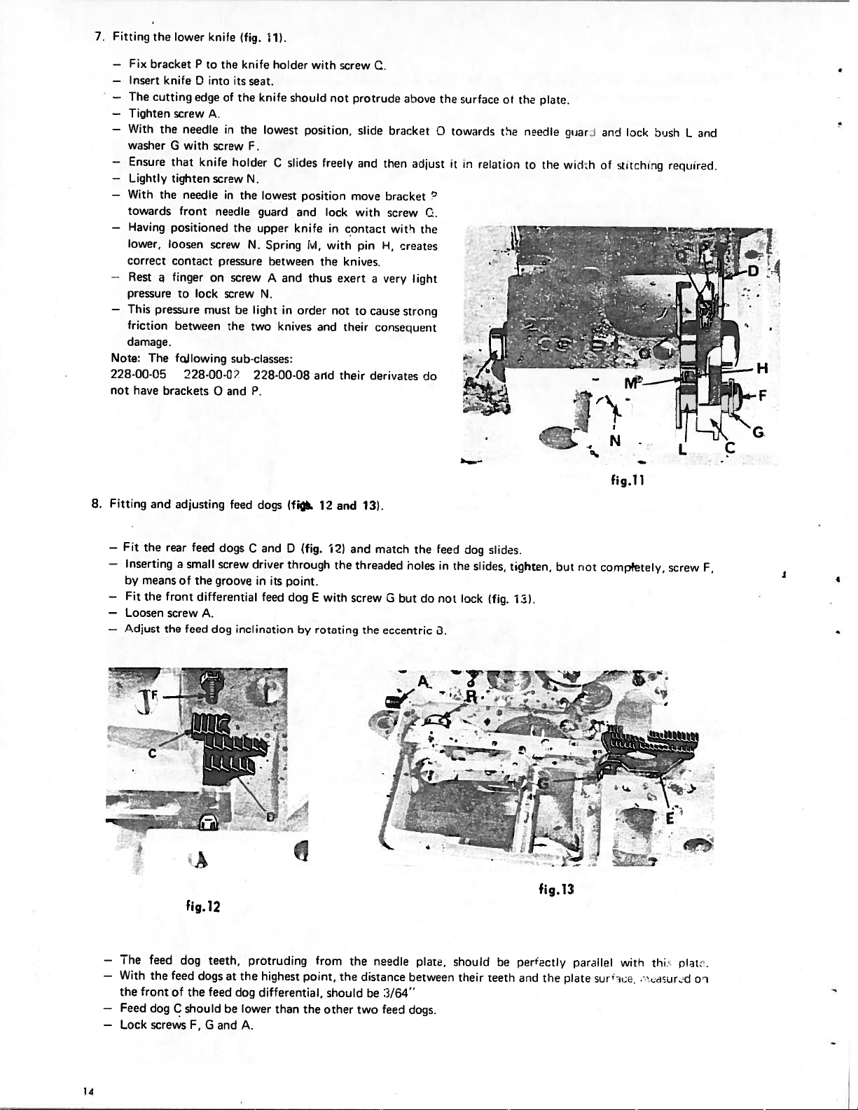
7.
Fitting
--
—
—
—
—
—
—
—
—
--
—
Note:
228-00-05
not
the
Fix
bracket
Insert
The
cutting
Tighten
With
washer
Ensure
Lightly
With
towards
Having
lower,
correct
Rest
pressure
This
friction
damage.
The
have
lower
knifeD
screw
the
G
that
tighten
the
front
positioned
loosen
contact
finger
to
pressure
between
following
brackets
P
edge
needle
with
knife
needle
lock
must
28-00-C2
knife
to
the
into
A.
screw
screw
needle
screw
pressure
on
0
of
in
in
screw
(flu.
knife
its
seat.
the
knife
lowest
the
F.
holder
N.
lowest
the
guard
the
upper
Spring
N.
screw
N.
be
light
the
two
sub-classes:
228-00-08
P.
and
1)
holder
should
C
slides
between
A
and
in
knives
with
position,
position
and
knife
lvi,
thus
order
freely
the
and
arid
not
lock
in
with
not
screw
move
contact
knives.
exert
their
their
C.
protrude
slide
and
with
pin
a
to
cause
consequent
derivates
bracket
then
bracket
screw
witi
H,
creates
very
above
adjust
the
lignt
strong
do
C.
the
J
‘
r
f;ici?
o
i
towar..ls
it
i
relation
:z4-
01
the
the
plit
edle
n
guard
and
lock
oush
L
and
thu
to
wid,h
of
sto:hi;ig
required.
i24
G
L
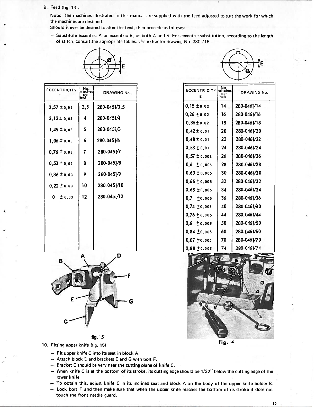
8.
Fitting
—
Fit
—
by
—
Fit
—
—
Adjust
and
the
Inserting
means
the
Loosen
adjusting
rear
a
of the
front
screw
the
feed
small
differential
A.
feed
dog
A
feed
dogs
C
driver
and
dogs
screw
grooveinits
feed
inclination
(fi%
D
(fig.
through
point.
dog
by
12
121
with
E
rotating
and
the
131.
and
threaded
screw
the
match
but
G
eccentric
the
noles
do
feed
in
not
B.
the
dog
lock
slides.
slides,
(fig.
tighten,
131.
but
riot
fig.11
compfetely,
screw
F,
fig.12
—
The
feed
—
With
the
the
front
—
Feed
dog
—
Lock
screws
14
feed
of
C
dog
the
should
F,
teeth,
dogs
feed
G
and
at
dog
be
protruding
highest
the
differential,
lower
A.
than
from
point,
the
should
other
the
the
distance
two
needle
be
3/64”
feed
plate,
between
dogs.
should
their
be
teeth
fig.13
perfectly
the
arid
parallel
plate
surt
with
e;e,
thi:
.eeaeur,d
plate.
01
Page 12
1
f—ced
Note:
the
Should
-
Substitute
of
(fig.
The
mechines
It
stitch
1’l).
iteichines
ever
consult
are
destined
he
(lesirirl
eccentric
lIri:,triterl
to
/oreccentric
the
ippropriute
alter
niinurl
in
the
this
feed,
tables.
un:
sLipplietf
then
procede
E
,
or
both
exti:rclor
Lse
and
us
follows:
For
I—
Ii
iwing
with
the
eccentric
No.
f,e(l
280-’1
idjiiste:I
substitution,
5.
tu
suit
iccordirrq
the
work
for
which
length
to
the
ECCENTRICITY
E
±0,03
2,57
0,03
2,12±
±
0,03
1,49
1,06±
0,03
±
0,03
0,76
±
0,03
0,53
±
0,03
0,36
±003
0,22
±0,03
0
B
No.
StiiChCS)
per
3,5
4
5
6
7
8
9
10
12
A
DRAWING
I
280-0451/3,5
280-0451/4
280-0451/5
280-045
280-0451/7
280-0451/s
280-0451/9
280-0451/10
280-0451/12
V6
0
No
ECCENTRICITY
E
0,15
±002
0,26
±002
0,35±0,02
0,01
0,42±
0,01
0,48±
0,53
±0,01
0,57
±0,008
0,6
±o,00s
0,63
0,005
±
0,65
±0,005
0,68
±0,005
+0,005
0,7
0,74
±0,005
0,76
+0,005
+0,005
0,8
0,84
±0,005
0,87
±0,005
0,005
0,88
-.
No
stitches
per
inch
14
16
18
20
22
24
26
28
30
32
34
36
40
44
50
60
70
74
DRAWING
280-0461/14
280-0461/16
280-0461/1
280-046V20
0461/22
280280-0461/24
280-0461/26
280-0461/28
280-0461/30
280-0461/32
280-0461/34
280-0461/6
280-0461/40
280,0461/44
0461/50
280280-
p461/60
280-0461/70
280-0461/74
No
8
F
G
C
fig.
15
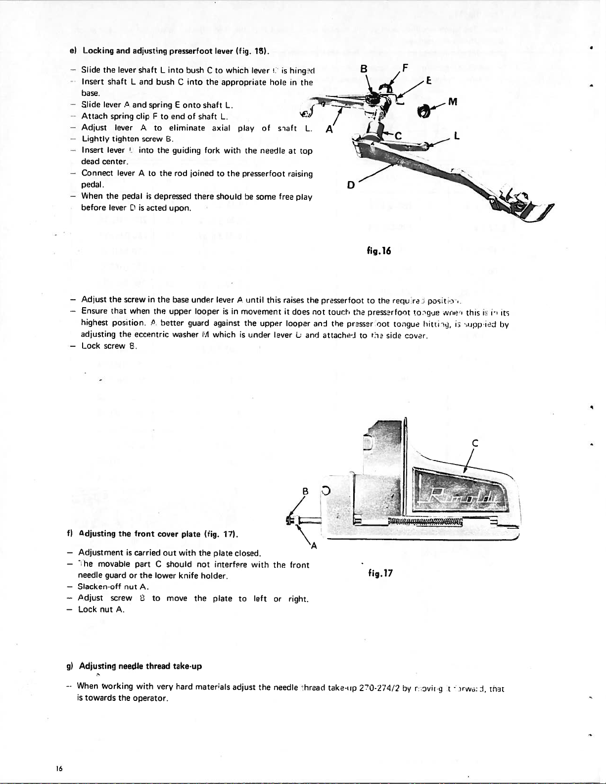
10.
Fitting
—
--
—
—
When
lower
—
To
—
touch
Fit
ttach
racket
Lock
upper
knife
upper
block
E
knife
knife.
obtain
boltFand
the front
knife
!.
should
C
this,
(fig.
into
C
and
be
isatthe
adjust
then
needle
15).
its
brackets
very
bottom
knife
make sure
guard.
seat
near
in
block
E
and
the
of
Cinits
with
G
cutting
stroke,
its
inclined
that
A.
when
bolt
plane
F.
of
its
cutting
seat and
the
knife
upper
C.
edge
block
knife
should
,c
reaches
on
be
the
the
1/32”
body
below
of
bottom
fig.
the
of
14
the
upper
its
cutting
knife
stroke
edge
it
of
holder
does
the
B.
not
5
Page 13
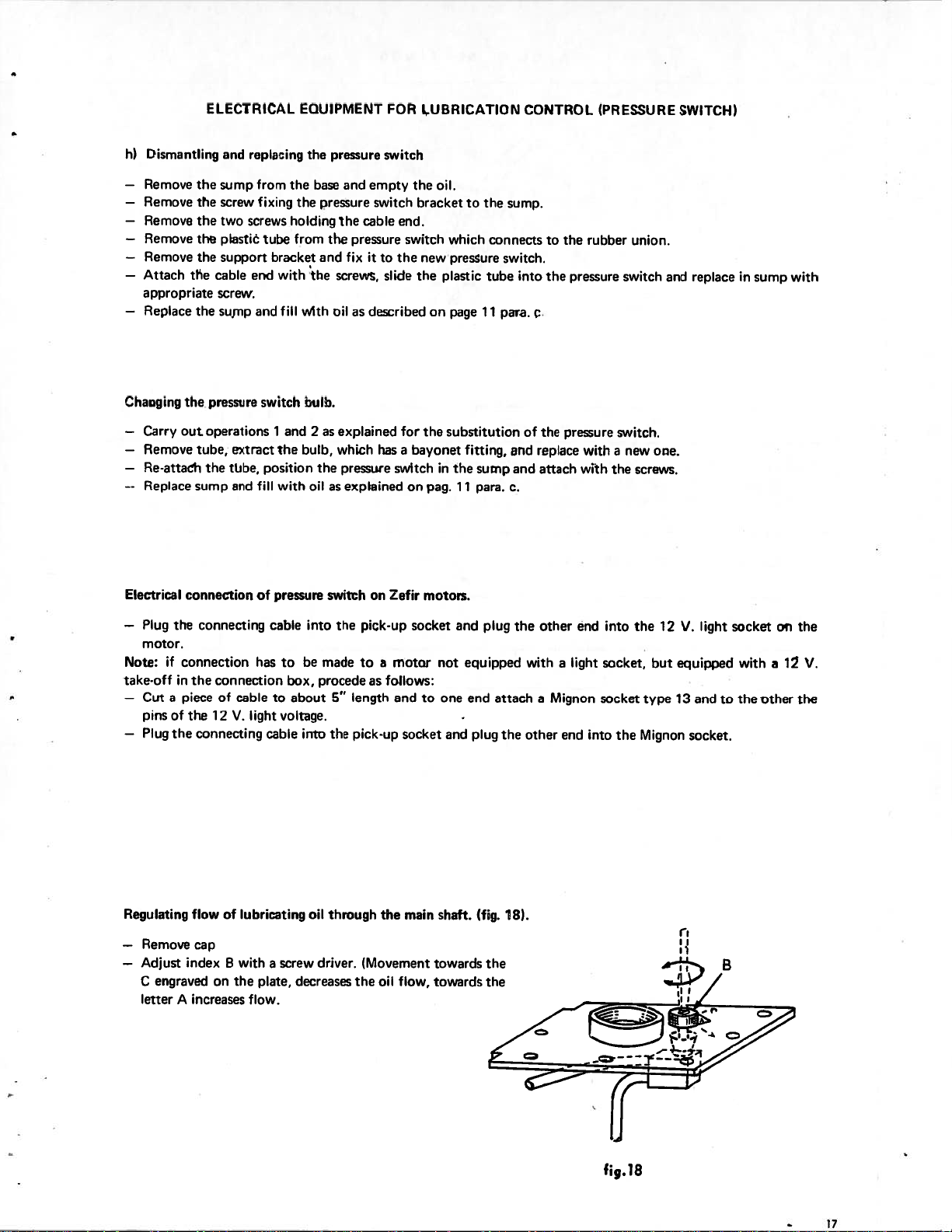
e)
1_ocking
and
adjestnq
presserfoot
lever
(fig.
15).
—
-
--
-
—
—
—
—
—
Slide
Insert
base.
Slide
Attach
Adjust
l_ightly
Insert
dead
center.
Connect
pedal.
When
before
Adjust
Ensure
highest
adjusting
Lock
the
shaft
lever
spring
tighten
lever
the
lever
the
that
position.
screw
lever
lever
lever
pedal
the
L
.
and
.
‘
screw
when
eccentric
E.
shalt
and
clip
,
into
A
is
spring
screw
to
is
acted
in
!
L
into
bush
F
end
to
eliminate
to
B.
the
guiding
the
depressed
upon.
base
the
upper
the
better
washer
E
rod
C
bush
into
onto
of
guard
shaft
joined
there
under
looper
C
the
shaft
axial
fork
‘I
which
to
appropriate
L.
L.
with
the
to
should
lever
in
is
against
which
lever
play
the
pressertoot
be
some
I
until
rriovement
the
upper
is
under
hole
of
needle
this
s
free
lever
hinij
is
in
aft
at
raising
raises
it
looper
play
does
L
the
top
ii
L.
the
not
anh
and
0
presserfoot
touch
the
presser
jttachei
B
the
to
fig.16
the
reqL
to
presserfoot
not
tosgue
t:1e
side
F
cover.
re
to:gJe
ps;t.e
hitti
Niiei
M
L
i
this
is
eipp
.
its
ii
si
by
adjusting
—
--
--
To
f)
Adjustment
—
-
he
needle
—
Slacken-off
isdjust
Lock
g)
Adjusting
When
is
towards
movable
nut
Working
front
the
carried
is
part
guardorthe
nut
A.
screw
A.
needle
with
the
operator.
cover
C
lower
to
thread
very
out
should
move
plate
with
knife
take-up
hard
(rig.
17).
the
plate
not interfere
holder.
the
plate
materals
closed.
to
adjust
with
left
the
the
or
needle
front
right.
A
thread
take-up
fig.17
2O-274’2
by
r,
oviru
t
:1,
tnst
Page 14
ELECTRICAL
EOU1PMENT
FOR
LUBRICATION
CONTROL
(PRESSURE
SWITCH)
Dismantling
h)
—
Remove
—
Remove
—
Remove
—
Remove
—
Remove
—
Attach the
appropriate
—
Replace
Chauging
—
Carry
—
Remove
—
Re-attach
--
Replace
Electrical
the
sump
the
screw
the
two
the
ptastiO
the
support
cable
screw.
the
sump
the
pressure
operations
out
tube,
the
sump
connection
and
extract
tUbe,
and
repIaing
from
fixing
screws
tube
bracket
with the
end
and
switch
1
the
position
fill
with
of
pressure
the
the
base
the
holding
from
fill
with
bulb.
and
2asexplained
bulb,
the
oil
pressure
and
empty
pressure
and
the
the
pressure
fix
switch
cable
it
to
screws, slide
oilasdescribed
which
hasabayonet
pressure
as
explained
on
switch
switch
the
brackettothe
end.
switch
the
new
the
for
switch
on
Zefir
oil.
which
pressure
plastic
page
on
the
substitution
in
pag.
motors.
fitting,
the
11
connects
tube
11
sump
para.
sump.
switch.
into
pare.
of
and
and
c.
to
the
c.
the
replace
attach
the
rubber
pressure
pressure
with
with
union.
switch
switch.
a
new
the
one.
screws.
and
replace
in
sump
with
—
Plug
motor.
if
Note:
take-off
—
Cut
pinsofthe
—
Plug
Regulating
—
Remove
—
Adjust
engraved
C
letter
the
connecting
connection
in
the
connection
a
pieceofcable
12V.light
the
connecting
flow
of
cap
index
B
on
A
increases
cable
has
cable
lubricating
with
a
plate,
the
flow.
to
box,
to
about
voltage.
screw
into
be
made
procede
5”
the
into
oil
through
driver.
decreases
the
pick-up
to motor
length
pick-up
(Movement
the
as
the
oil
socket
follows:
and
socket
main
flow,
not
to
shaft.
towards
towards
and
equipped
one end
-
and
plug
plug
(fig.
the
the
the
attach
the other
8).
with
other
Mignon
a
a
end
end
light
into
into
socket,
socket
the
12
the
but
V.
equipped
type13and
Mignon
Ii
light
socket.
socket
with
to
the other
on
the
a1V.
th
fig.18
—
17
Page 15
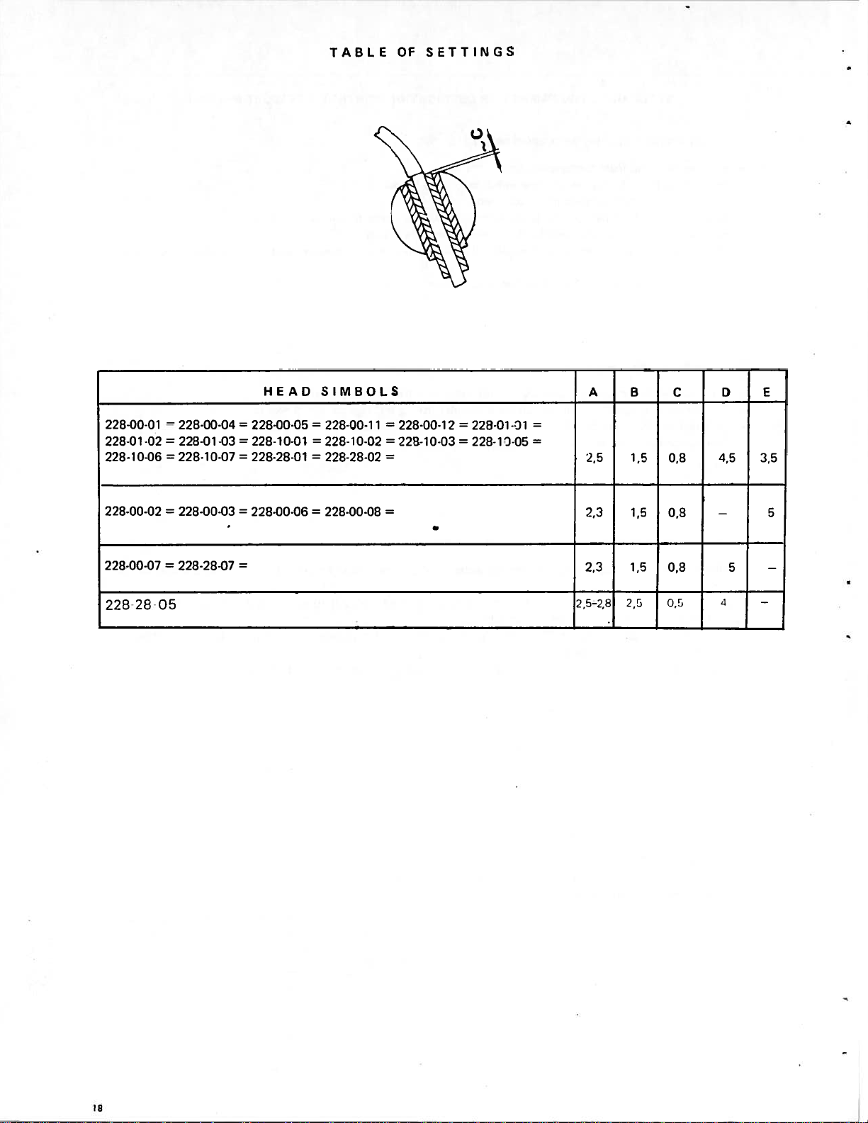
TABLE
OF
SETTINGS
228-00-01
=
228-00-04=228-00-05
228-01-02=228-01-03
228-10-06 228-10-07
228-00-02=228-00-03
=
228-00-07
228-28-07
228-28-05
HEAD
228-10-01
=
228-28-01
=
228-00-06
=
SIMBOLS
228-00-11
=
228-10-02
=
228-28-02
=
228-00-08
228-00-12
=
228-10-03
=
=
228-01-D1
228-13-05
A
=
2,5
2,3
2,3
2,5-2,8
B
C
1,5
0,8
1,5
0,8
1,5
0,8
(j,5
25
4,5
—
4
E
D
3,5
5
5
—
—
18
Page 16
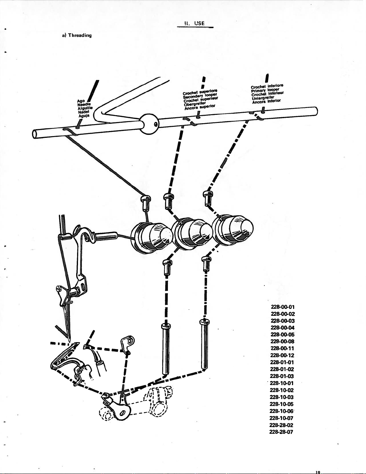
USfS
.
a)
Thread
Ago
Needle
Alguille
Nadel
Agula
inq
1’
Crochet
Secondary
Crochet
Obergreiter
Ancora
I
I
superior.
looper
superieur
supertor
Crochet
Primary
Crochet
Unlorgreiler
Ancora
I
Interior.
looper
inlérteur
interior
I
I
I
/
I
228.00-0.,
228.00-02
228.00-03
228.00-05
228.00-08
228.00-11
228.00.12
228.01.01
228.0102
228.01.03
228.70.01
228.10-02
228.10.03
228-10.05
228.10-o6
0-07
228-i
228.28.02
228.207
Page 17
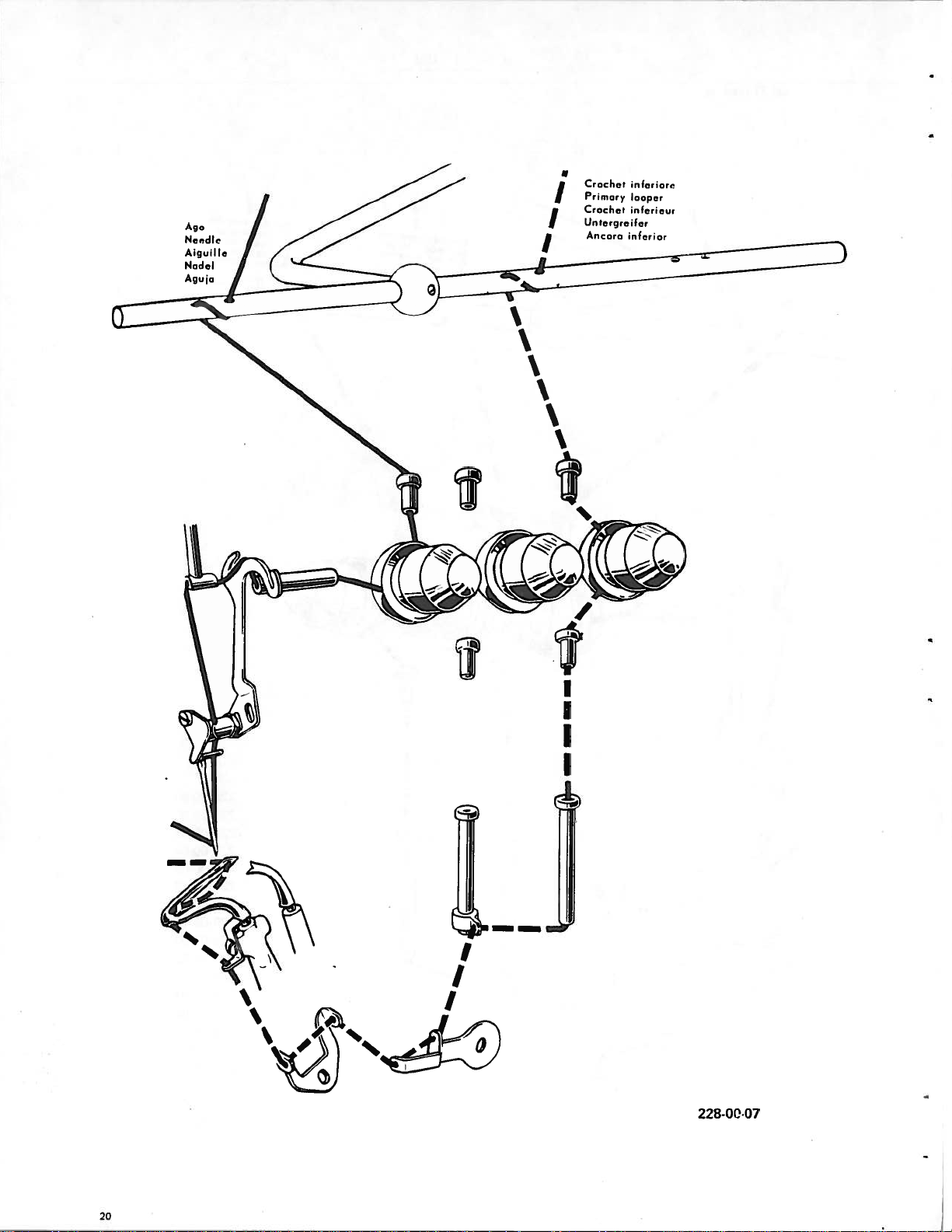
Ago
Nedl
A
Nodal
Ag,
10
guilje
I
‘
‘
a
Crochet
Primary
I
Crochet
linteryrorfer
Ancora
k
‘flhc•rior,.
looper
flfCrIeur
I
I
I
228-OQ-07
20
Page 18
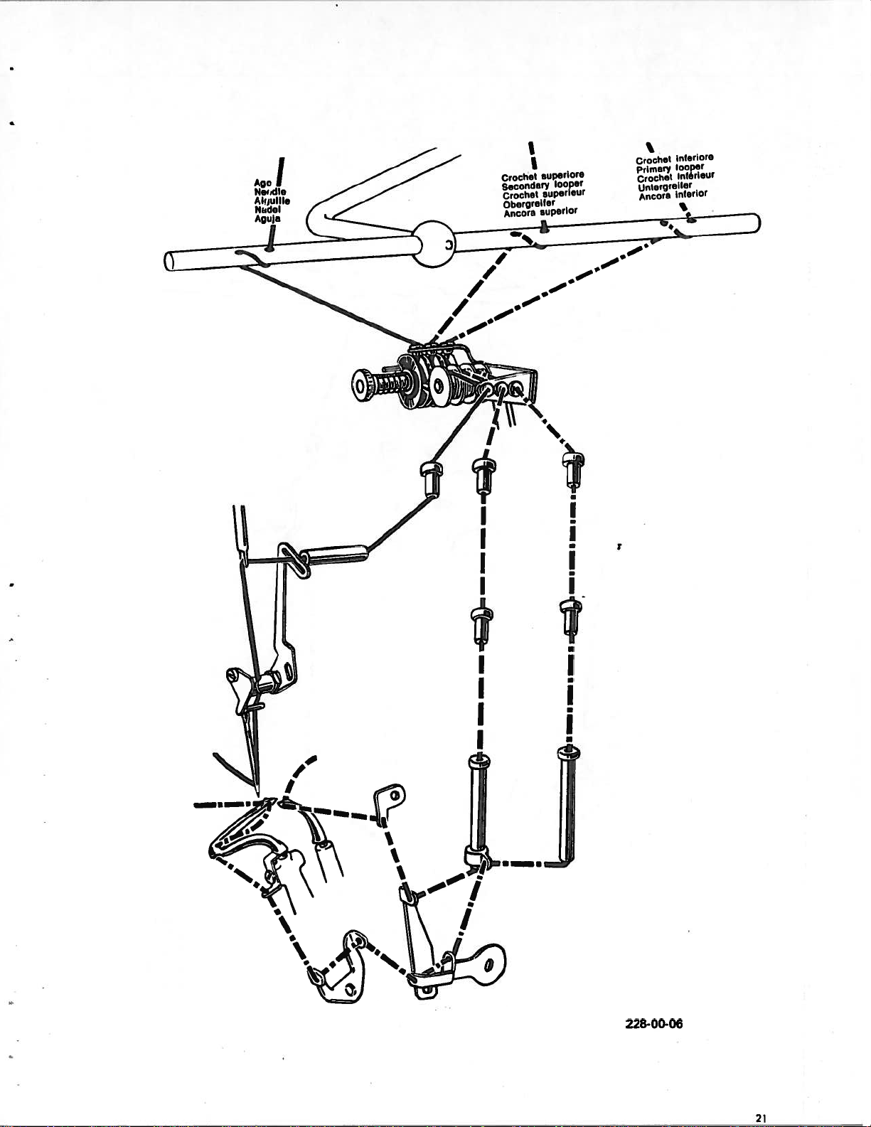
I
Crochet
Secofldery
Crochet
Obergrelter
.ncora
I
euperlore
euperleUr
euperlor
looper
Crochet
prlmftPl
Crochet
lJnLerqreIter
ncora
InferiOre
looper
nterIeUr
lnt00r
I
t
I•
•
I
I
I
=
228-00-06
21
Page 19
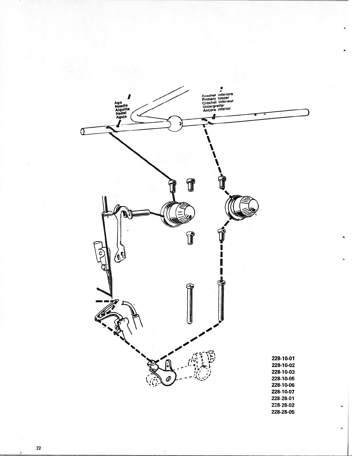
nicriora
CrOCh
I
primary
Crochet
nmerqt0
AncOra
oopor
irrierleUr
or
inlerlOr
7,
I
228-10-01
228-10-02
228-1
0-03
228-10-05
228-10-06
228-10-07
228-28-01
228-
28-02
228-28-05
22
Page 20

10.
11.
12.
1.
2.
3.
4.
5.
6.
7
8.
9.
Lnanging
b)
Switch
L’epress
Muve
Press
emovu
Slacken
driver
lemove
Fit
new
The
notch
towards
of
the
Using
iouches
Tighten
position
o
not
the
off
the
the
pedal
needle
the
leverPright
presserfoot
the
needle
the
11
91/2.
ns’rlle.
the
needle.
through
the
reai
machine.
tweezers
the
end
the
the
locking
of
the
over-tighten.
neetfie
motoi
to
needle
of
needle.
which
top
clown
locking
which
the
screw
starts
dead
(fig.
from
the
guard,
supplied
needle
being
the
center.
9).
its
screw
looper
that
holder.
motor
working
half
is
ensure
careful
to
position.
turn
a
passes
towards
that
nottoalter
ensure
with
should
th
the
the
screw
face
interior
needle
machine
the
is
completely
B
G
off.
1.
2.
3.
4.
5.
6.
1.
2.
Posicioning
c)
Check
The
adjust
o
Center
To
knob
Lock
Tension
d)
Tighten
Never
Stitch
e)
For
stitch
correct
needle
should
presserfoot
the
presserfoot
increase
A.
knobAwith
adjustment
tensioners
the
tighten
length
length
and
positioning
or
decrease
much
too
adjustment
adjustment
adjusting.
pass
slacken
in
screw
pressertoot
presserfoot
of
between
off
correct
the
presserfoot
the
6.
sufficiently
(fig.
see
the
screw
14).
para.
presserfoot
F.
position
permit
to
9
Feed,
a)
pressure
shoe
and
pressure,
a
pag.
Ifia.
lock
slacken
regular
and
15.
F.
l9).
tongue.
stitch
off
formation.
screw
fig.
19
with
sparner
633-742
and
adjust
6
Adjustment
1.
2.
3.
4.
5.
f)
The
To
vary
Slacken
Slacken
Move
Lock
Lower
seam
upper
screw
width
the
off
off
knife
width
screw
screw
knife
F
(fig.
holder
seam
of
can
onlybevaried
within
N
in
F
(fig.
support
15).
widtn.
these
the
lower
15).
A
re-setting
(fig.
fine
knife
15)
should
to
a
limits
holder
to
rightorleft
be
very
proceed
carried
limited
(fia.
as
11).
out
extent
follows:
till
desired
in
accordance
after
seam
which
width
with
the
is
needle
obtained.
the
instructions
plate
has
to
be
changed.
in
para.
7.
a)
23
Page 21
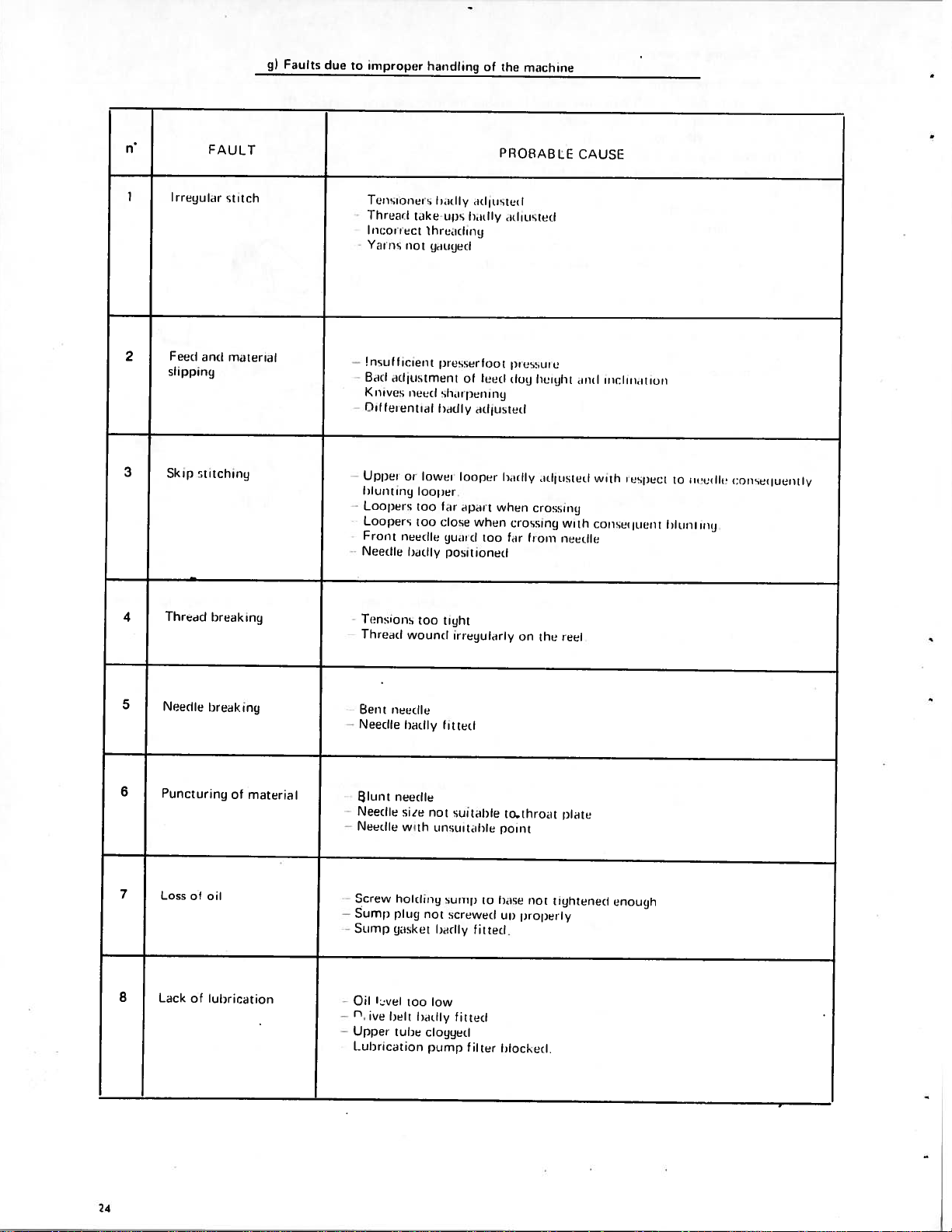
ij)
Foults
due
iinpropt,r
to
hutidling
of
tiw
nincliinn
fl
I
2
3
i
I
sju
Fold
slipPiflg
Skip
FAUI.T
lii
(nil
stitching
stitch
motel
PROBABLE
si
Tet
into
idly
ii
el
of
lOu
looper
liii
l)iill’
rig
I
irl1usrud
when
rI
Icil
too
0
flij
i
st
loudly
when
fir
iditistitil
)IitstLiiU
log
crossing
from
—
F1i
ii
tikit
iti:t
riot
irtitO
or
lOoj
too
too
needle
badly
hi
t
jilutfiji
I
lower
iiiis
piussuirlont
sItu
barfly
icr
lii
lose
gUii
positioned
liii
——
I
Vii
us
iii
!nsulficiuoi
Boil
lvi
Kit
Oil
luluential
odlristnuent
Uppot
f
ii
Ohtlug
—
Loopers
Loopers
Front
Needle
height
ilIftistliti
ci
ossung
c;AUSE
nuel
with
nucrlliu
iiiu:lurritiuuu
with
inspect
(;oirsru(j000i
to
h1uotiiu
tuttle
i:oosurjuuiitl
/
Thrwid
4
5
Needle
6
Puncturing
7
Loss
8
Lack
break
&
oil
of
lubrication
breaking
of
ny
materia
Tensions
Thi
end
Bent
needle
Needle
I
lunt
needle
Needle
Needle
Screw
Sump
Sump
Oil
.
ive
Uppei
holding
plug
gasket
Led
belt
tLihe
—
—
--
f_uhricutioii
wound
badly
size
with
too
too
not
unsumtilrle
not
badly
low
badly
clogged
1Jun11)
tight
irregularly
lit
ted
sui
sump
screwed
fitted
Ill
table
fitted
ten
to
tothroat
Point
hose
LII)
I
docked
on
the
reel
plate
not
tightened
open
Pb
y
enoLigh
24
Page 22
briefly
1.
2.
3.
1.
2.
3.
4.
Air
5.
Soak
Every
a)
clean
Every
b)
Remove
.‘pen
‘arefully
Every
c)
Using
Remove
Extract
blast
front
the
felt
day
all
week
needle
cover
clean
three
spanner
screw
filter
filter
with
machine
plate
plate
inside
months
supplied,
007-
and
and
clean
parts
and
the
L
clean
sump
and
oil.
clean
plate
20
relating
carefully
remove
which
by
immersing
plug.
to
the
feed
clean
covering
the
attaches
feed
dogs,
the
sump
Ill.
MAINTENANCE
and
stitch
needle
inside
needle
drain
filter
in
petrol.
formation.
guards
movement
plug
and
to
plug.
and
assembly.
drain
loopers.
off
oil
completely.
.
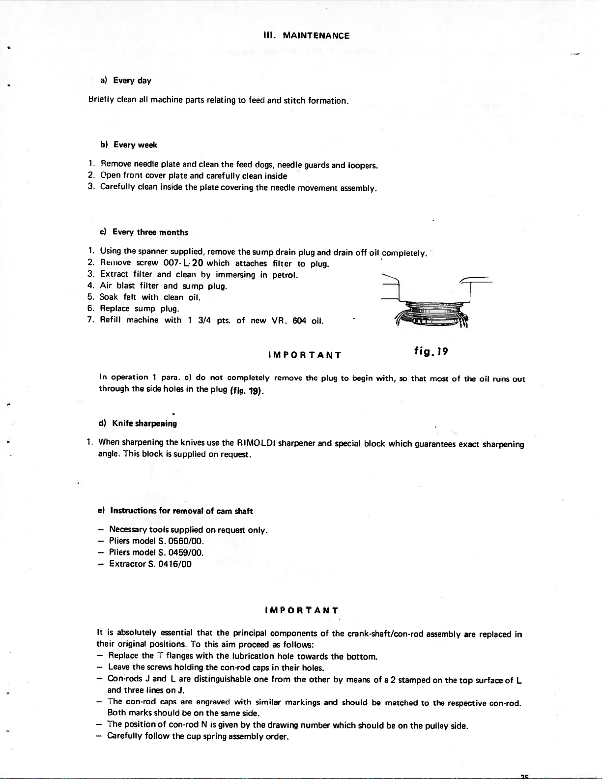
1.
In
operation
through
Knife
d)
When
angle.
Instructions
e)
—
Necessary
—
Pliers
—
Pliers
—
Extractor
the
side
sharpening
sharpening
This
block
tools
model
model
S.
1
para.
holes
the
is
for
S.
S.
0416/00
1
c)
in
knives
supplied
removal
supplied
0560/00.
0459/00.
3/4
do
the
not
plug
use
on
of
on
pts.
completely
ffja.
the
request.
cam
shaft
request
new
of
19).
RIMOLDI
only.
yR.
604
IMPORTANT
remove
the
sharpener
oil.
and
plug
to
special
begin
block
with,
so
which
fig.19
that
most
guarantees
of
the
exact
runs
oil
sharpening
out
IMPORTANT
is
It
their
—
—
—
Con-rods
and
—
The
Both
—
The
—
Carefully
absolutely
original
Replace
Leave
three
con-rod
marks
position
the
positions
the
screws
J
and
lines
should
follow
essential
flanges
T
holding
L
on
caps
of
con-rod
the
that
To
this
with
are
distinguishable
J.
are
engraved
be
on
N
cup
spring
the
the
is
the
the
given
principal
aim
proceed
lubrication
con-rod
with
same
assembly
side.
by
caps
one
similar
the
drawing
order,
components
as
follows:
hole
towards
in
their
holes,
from
the
markings
number
other
of
the
the
and
crank-shaft/con-rod
bottom.
by
means
of
should
which
be
should
assembly
a
2
stamped
on
matchedtothe
be
on
pulley
the
are
the
top
respective
side.
replaced
surface
con-rod,
in
of
L
Page 23
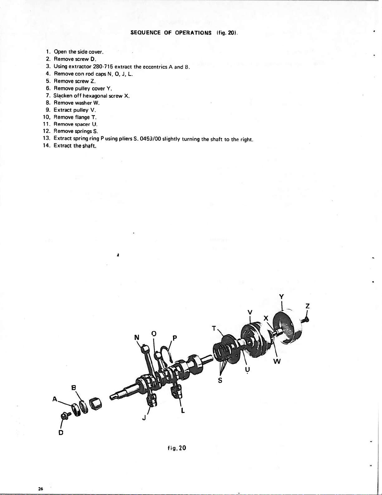
10,
11.
12.
13.
14.
1.
2.
3.
4.
5.
6.
7.
8.
9.
Open
Remove
Using
Remove
Remove
Remove
Slacken
Remove
Extract
°emove
Remove
emove
Extract
Extract
the
side
screw
extractor
rod
con
screw
pulley
off hexagonal
washer
pulley
flange
spacer
springs
spring
the shaft.
cover.
D.
280-715
caps
Z.
cover
W.
V.
T.
U.
S.
ring
P
N,
Y.
screw
using
extract
J,
0,
pliers
SEQUENCE
the
L.
X.
0453/00
S.
eccentrics
OF
OPERATIONS
an’J
A
slicihtly
b.
turning
the
shaft
fig.
20).
to the
right.
V
V
T
N
P
w
y
S
L
J
fig.
20
26
Page 24

U)
m
-I
U)
-I
0
I
0
C
m
Page 25

Page 26

Page 27

Introduction
a)
HOW
I.
TO
USE
fHIS
CATALOGUE
1
This
up
In
2.
the
The
3.
4.
In
On
5.
assemblies,
and
of
The
6.
machine
spare
parts
the
basic
head
ordertomake
head.
conversion
tables,
the
each
equipment
each
catalogue
the
table
whose
table
and
and listing
catalogismarIeupofaseriesoftables
sub-classes.
and
its
the
useofthis
assembliesofthe
numbers
various
the
components
not
normally
illustrated
are
general
has
a
the
table
catalogue
basic head
which
identify
components
cannot
with
the
complete
numerical index
which
on
II.
HOW
easier,
and
the
of
the
be
supplied
machines
with
the
parts
TO
its
sub-classes
a.semhly
but
all
giving
are
ORDER
illustratnq
the table
sub
classes
are
illustrated,
separately,
which
canhesupplied
their
particularsatthe
the
cross-reference numbersofall
illustrated.
SPARE
the
index
shows
are
iliustracadinsinqle
printed
are
at
are
crossrefere
PARTS
various
parts
the
positionofsuch
rioht
top
cross-referencea
on
reauat,
end
-of
assemblies which
or
tables.
of
the
in
book.
black.
by
are
giveatthe
compo
page
iced byacapital
assembly
number. The
a
letter.
cent
partsofthe
make
inside
Parts
botto:
a)
To
1.
Quote
Quote
2.
G)ve
3.
4.
The
The
manufactured
spare
b)
1.
Only
The
2.
he
3.
needle.
4.
The
5.
When
RIM
6.
In
7.
For
All
parts
ensure
immediate
serial
the
drawing
the
full
the
quantity.
RIMOLDI
parts.
Needles
caseofdoubt
straight
needie
size
ind;cates
system
ordering
27).
stitching
only
system
and
dispatch
numberofthe
numberofthe
nameofthe
Company
by
them.
system
elastic
and
the
size
always
send
RiM
average
are also
or
part required.
likes
For
needles
27
are
size
shown
give
the
a
sample
elasticised
of
required
head.
part
to
this
reason
marked
diameter
system
needle
materials
should
on
required.
analyse
they
on
expressed
the
and
or
spare
IMPORTANT
any
kindly
be
usedonthe
the
needle
packets
size
ar
empty
there
parts,
casos
in
hundredths
containing
of
the
packet
are
ball
following
the
of
breakage,
ask
youtoreturn
machines
shank.
needle
of
point
of
a
RIMOLDI
reouired
the
type
needles
instructions
wear
such
iiljstrated
limeter
needles.
e.g.
reoured.
classified
shouldacarefully followed:
or
irregularhie’;
pieces
along
in
this
calculated
n.
1QJ
SKU.
ma’ual.
needles
with
on
arising
the
the
size
dade
dO
in
order
systerr,
of
parts
for
the
29
Page 28

INDEX
OF
TABLES
BUSHES
STUDS
BASE
MAIN
CON—RODS
DIFFERENTIAL
ASSEMBLY
—
THREAD
PRESSED
SHAFT
INTO
WITH
GUIDES
THE
Toy.
Toy.
2
3
4
SHAFTS
OPERATING
NEEDLE
MECHANISM
UPPER
KNIFE
AND
AND
MECHANISM
CON—RODS
LOOPER
DRIVE
LOWER
Toy.
Toy.
Toy.
5
6
7
31
Page 29

PRESSERFOOT
MECHANISM
NEEDLE
CASING
WORK
THREAD
TENS
—
PLATE
ION
PLATE
GUIDES
E
RS
LIFTING
—
AND
Tav.
Toy.
Tov.
8
9
10
11
12
13
:r(..’9
‘,
[1
AND
SUMP
MACHINE
BRACKET
KNEE
REEL
AND
ACCESSORIES
OIL
MOUNTING
AND
CONTROL
HOLDERS
PEDAL
PUMP
Toy.
15
32
Page 30

HEAD
“
“
“
“
“
22B00-02
228-00-03
228-00-04
228-00-05
228-00-06
2280-07
Tab.
lah.
Tab.
lab.
lab.
ab.
19
20
21
22
23
18
HED
228-10-01
228-10-02
228-10-03
228-10-05
228-10-06
228-10-07
Tab.
Iab
Tatj.
ab.
Tab.
lab.
30
31
32
33
34
35
‘
“
“
‘
“
“
228-00-08
228-00-11
228-00-12
228-01-01
228-01-02
228-01-03
Tab.
lab.
Tab.
Tab.
lab.
Tab.
25
26
27
28
29
24
TABLE
TABLE
PARTS
228-28-01
228-28-02
228-28-07
Wi
(100)
Xl
(101
ON
REQUEST
36
lab.
lab.
37
Tab.
38
lab.
39
Tab.
40
Tab.
41
.
Tab.
42
I______________________
Page 31

Page 32

22800-01
228-28-05
1
I.
S
REF.
3
4
5
6
7
8
1
2
PART.
270-016
202125-0-1
270-058
270-057/1
270-268
270-938
280-010/3
2041093-l1
a
DESCRIPTION
bush,
1
2
shaft
bush knife
bush
rear
bush
front
tubes
thread
bolt
bush
bush
main
base
with
holder
shaft
bush
guide
and
thread
guides
1
9
1
10
11
2
12
2
13
1
14
1
1
PART.
270-264
204107-0-Il
270-642
280-830
270-082/1
270-912
thread
base
studs
lube
bush
Icinkliuj
guide
machine
cover
centering
oil
presserfoot
presserfoot
oin
DESCRIPTION
needle
lift
work
plate
1
1
2
1
1
1
Page 33

22H-UU-U1
2
22
24ft
24
254i\
II
21
\—___
J26
3g
l8
6
I,,
4\
I
“I
,‘
4
4
‘5
i____j”%%j
S
7I”l
27
5
--:;S
“\“2
Rh.
PM280.009/4
1
270-704
2
270-705
3
4
270-620
5
270-614
270-008/1
6
7
270-612/1
8
2
128-608/5
9
10
270-610
11
780-009/4
270-707
171
010-H-i
13
14
20-975
790-944
15
PM.270-060/1
16
10-981
PART.
3,7
main
seeger
spring
ffange
spacer
pulley
washer
bolt
cover
stud
main
ball
-bolt
bolt
screw
con-rod
shaft
ring
right
right
with
pulley
pulley
pulley
shaft
bearing
for
con-rod
coupling
guide
with
DESCRIPTION
complete
for
right
side
guide
fixing
right
280-012
fixing
coupling
bearing
REF.
1
17
1
18
4
19
1
20
1
21
1
22
1
23
24
1
1
25
1
25
1
27
28
2
and
270-116
3
-
2
-i
29
4
33
1
1
1
1
1
17
29
PART
PM.270-05’3
270-052
280-925
21-10-019
032-D-25
023-N-5,5
001-E-10
01
0-U-i
280-0123
270-1162
30-06i
270-050,1
370-95-3,1
70-6i
3
POP
HEAD
PM236
33i3-OO3
PM270-060,
270-060
1
1,5
2
5-0033
3
1
DESCRIPTION
1
con-rOd
with
228
guide
bolt
woodruff
wick
screw
bolt
bolt
con-rod
con-rod
i.un-ioif
coupling
couiding
spacer
28-05
main
main
coin-rod
cuuplinq
con-rod
eccentric
for
shaft
gudqeon
flange
for
looper
needle
knife
upper
con-rod
con-rod
bearing
shaft
shit
with
con-rod
coupling
locking
key
shalt
looper
complete
couialinq
pin
locating
con-roil
bar
1
2
2
3
8
1
2
1
1
Page 34

228-00-01
3
8
9
\.
22
‘‘
24
13
/
4
I
A)’
1
12
28
29
27
31
21
20
REF.
PM.280-049/1
1
2
280-31
026-C
3
4
280-023
5
270-935
092-31
6
7
270-039
8
270-937/1
092-D-1
9
10
270-035,1
11
280-035
12
280-034
13
280-926
14
280-0451/10
280-0151
15
004-L-7
16
17
230-048
PART.
1/1
-7
1
1
1
DESCRIPTION
slide
chfferentiiil
block
sliding
screw
countersunk
bolt
for
feed
dog
shaft
for
for
slide
fixing
fixing
holder
for
differential
subsidiary
differential
feed
feed
dog
dog
washer
wick
eccentric
screw
shaft
wick
block
sliding
bushing
bushing
nut
‘9
eccentric
eccentric
screw
connector
slide
Joint
shield
oint
REF.
1
13
1
19
1
23
2
21
3
22
1
23
1
24
1
25
2
25
27
1
1
28
1
29
2
30
1
31
1
A
2
3
1
2$0-033i1
280-253
270-540/3
005-L-1
071-1-1-5
230-207/2
026-C-7
270-978
270-050
280-051
270-052
270-977
270-250/2
270-249/1
280-09/1
280-043/1
PART.
1
connector
gasket
guide
screw
washer
guard
screw
screw
feed
feed
feed
screw
shield
shield
slide
slide
On
280-C51
30
19
-—---i
slide
block
guide
oi
oil
guard
differential
dog
differential
dog
subsidiary
dog
chaining
subsiiiary
rubber
main
feed
subsidiary
request:
j::;
5
i:
DESCRIPTION
block
fixing
fixing
feed
feed
dog
feed
dog
dog
dog
fixing
fixing
Tab
1
1
1
2
1
1
2
1
1
1
1
1
1
1
1
-
38
Page 35

226-28-05
4
8
g
\j
6
10
.‘rl
20
\-
REF.
PART.
5
22
/
2I
26
N)
DESCRIPTION
REF.
PART.
DESCRIPTION
10
11
12
1Cr
1
2
3
4
5
6
7
8
9
PM
2868-049
286
B-61
C-?
026
280-023
-270-935
8-1
292
270-039
270-937i1
092
0-11
276
8-036
286
8-034
280-926
286
S-0
1,1
1
1
slide
differential
block sliding
screw
contersunk
bolt
for
washer
wick
eccentric
screw
shaft
wick
block sliding
bushing
loint
slide
nut
spacer
feed
shaft
dog
fixing
holder
for
differential
14
230-04561
1
15
004
1
16
230-033.
1
17
236
2
18
26
19
005
1
20
276
1
21
236
22
326
23
270-978
1
24
286
1
25
276
1
26
270-249,1
1
L-7
B-253
8-640
1
L-1
B-5
8-207
C-7
0-050-1
8-250
5
eccentric
1
1
screw
connector
gasket
3
guide
screw
1
washer
guard
screw
screw
feed
1
shield
shield
dog
shiek
block
guide
oil
oil
feed
ui
for
slide
guard
dog
her
teed
fixing
block
fixin
fixing
dog
fIxing
1
2
2
1
1
Page 36

—I
228-00-01
6
2
7
8
4
H
10
5
N
1
092-0-16
2
073-N-b
3
270-070
4
270-064
5
27277-074
270-075/2
6
7
270-069
8
250-471
270-068/3
9
10
G.270-065/3
PAIT.
wick
looper
washer
for
gudgeon
shaft
upper looper
lower
shaft
bolt
holder
guide
pin
upper
looper
lower
looper
lower
oscillatinq
DESCRIPTION
shaft
looper
shaft
upper looper
looper
with
small
with
small
looper
lever
Inoper
with
eye
screw
eye
lever
for
bush
cotton
13
REF.
2
11
2
12
1
13
1
14
1
15
1
i
2
17
1
18
1
A
1
B
C
D
270-974/1
016-B-4
016-0-2,5
270-067
092-B-i
017-F-il
092-D-7
016-B-3
270-053
270-056/2
270-065/3
270-063/2
P1.
screw
fixing
grub
lever
gudgeon
screw
wick
grub
ring
bush
guide
holder
On
request:
looper
screw
screw
upper
pin
bush
screw
play
adjustment
adjustable
oscillating
upper
DESCRIPTION
fixing
for
upper
gudgeon
looper
wick
fixing
looper
loopers
27.277-0745
270-D-074/1
270-075
looper
pin
shownintab.
gudgeon
2
pin
1
1
2
1
2
1
1
38
FOR
5
270
D-074,1
6
270-075
HEAD
228-28-05
upper
lower
looper,
looper
blind
1
Page 37

228:08-Ui
6
5
—7
3_
2
-
29
3
H
‘_r
j
.
j\
\/\
l
\,/
,3\
34
13
21
1
10
8
\
\
(j,
I
•Fi
;I
/,-
11
15
j’•
7
30
/
25
19
31
32
.-
26
25
‘I
24
23
20
A
1
REF.
10
11
12
13
14
15
16
17
18
1
2
3
4
5
6
7
8
9
PART.
PM.270-1
PM.270-137/i
270-132/1
270-728/1
290-027/1
270-933
270-713
270-006/1
073-F-9
270-719
007-C-i
270-007/1
270-975/1
270-031/1
092-D-6
071-8-5
001
-G-i
0
270-708
DESCRIPTION
38/1
1
shaft
for
fork
lever
bush
for
screw
ring
for
nut
for
spring
shaft
operating
washer
collar
collar
screw
attachment
attachment
gudgeon
wick
gudgeon
washer
washer
bolt
bearing
fork
fork
bush
fixing
needle guide
guide
washer
for
upper shaft
for
upper
shaft
screw
pin
for
upper
for
holding
for
upper
lever
lever
bsr
slide
shaft
attachment
pn
shaft
for
shaft
bar
lever
270-007.1
REF.
19
1
1
20
1
21
22
1
1
A
B
1
1
23
24
1
2
25
13
2
27
2
1
28
1
29
1
30
1
31
1
32
1
3.3
1
3-
21
A
PART.
250-708,1
016-8-2,5
G.270-025,2
RIM. 27
770-020/1
2-20-025/1
‘cL,5
003-’-
270-130
092-B-i
016-A-2,5
270-1.35
092-0-5
270-133/1
023-N-5,5
00i-E-7
170-131
092-0-1
0)2-A-i
0
FOR
G27.77-025,2
27,77-020
DESCRIPTION
for
roller
gudgeon
needle
retaining
gudgeon
needle
slide
gudgeon
screw
upper
for
needle
bar
shim
needle
pin
drive
pin
fixing
shaft
shaft
needle
bearing
holder
clamp
pci
bar
pin
fork
holder
pin
bar
needle
wick
end
bar
fixing
lever
needle
needle
-
retaIning
bar
drive
drive
lever
lever
1
1
1
2
2
1
1
1
1
1
1
cage,
screw
assembly
needle
clamp
needle
screw
gudgeon
wick
screw
bar
wick
qudgeon
grub
bolt
HEAD
washer
wick
wick
228-28-05
assembly
clamp
1
Page 38

228-00-Ui
2
28
-3
14
7
çcbsJ
l6jJ
8
29
R
1
1
2
3
4
5
6
7
8
9
10
1
1
1.2
13
14
15
270-102
270-096/1
270-1
2777-228
128-111
270-987
270-099
270-T03
073-F-9
270-19
Oçl7-C-1
270-108/1
270-098
U92-C-2
092-D-9
12
PT.
DESCRIPTION
pin
for
upper
knife
holder
upper
knife
upper
guard
guard
upper
bolt
upper
upper
upper
for
ring
lock
pin
gudgeon
knife
for
fork
knife
upper
ring
holder
block
snug
washer
1
lock
screw
gudgeon
coupling
wicks
wick
knife
serrated
knife
knife
knife
upper
for
pin
holder
fixing
holding
locking
knife
knife
attaching
holder
holder
fork
RE.
1
16
1
17
1
18
1
19
1
20
1
21
1
22
1
23
1
24
1
25
1
26
1
27
1
28
29
2
1
30
3
21
31
250-471
007-P-b
071
-D-5
270-104
270-105
270-113/1
270-100
270-106
003-L-12
270-101
070-F-4
270-877
02&B-5
004-A-S
27
77-227
FOR
276
B-112
277-113
128-110
PART.
HEAD
bolt
screw
washer
holder
,haft
knife
spring
for
pin
bolt
bush
washer
bolt
bolt
screw
stop-plate
request:
On
270112/2
270.113/2
228-28-05
knife
knifelower
waste
for
upper
lower
lower
lower
lower
lower
lower
lower
knife
support
bush
for
lower
for
upper
guard
upper
trimming
DESCRIPTION
knife
knife
knife
knife
knife
knife
knife
holder
guide
knife
knife
fixing
rear
needle
serrated
fixing
holder
fixing
shield
driving
shaft
holder
bush
holder
guard
Tab.
lever
39
39
1
1
1
1
1
1
1
1
.1
1
1
1
1
1
1
1
1
1
Page 39

228-OOO1
,,
i\
S
29TI
24’l8
&‘23’)25
12
32
,,_
14
31
26
4
REF.
4
5
9
10
11
12
13
14
15
16
17
1
2
3
6
7
8
PART.
270-077
270-081/1
270-083
092-C-2
PM.270-076J2
270-087/1
270-985
270-089/1
270-71i
270-701
270-076/2
PM.270-081/1 shaft
270-073
270-085/1
270-091
004-L-7
270-183
‘
pin
for
shaft
of
for raisable
bush
wick
asssembly
presserfoot
lever
screw
spring
ring
snap
enap
ring
lever,
pipe
pin
adjusting
nut
bolt
preserfoot
block
presserfoot
presserfoot
presserfoot
for
presserfoot
for
presserfoot
presserfoot
DESCRIPTION
holder
raising
lever
holding
raising
raising
raising
holding.
tongue
lever
lever
raisable
lever
lever
lever
REF.
1
18
1
19
1
20
4
21
1
22
1
23
1
24
1
25
1
26
27
1
1
28
1
20
1
30
1
31
1
32
1
33
1
-
PART.
270-106
2’0-101
270-109/1
20-184
2’O-l
35
270-980
001
-fs-3,2
G.2’0-181
270-1141
270-107/1
2?0-936/2
270-9342
092-D-1
032-L-10,5
G.270-076
12
PM.273-085
DESCRIPTION
locator
bracket presserfoot
rear
needle
presserfoot
shoe
plate cha:n
block
ecrew
screw
plate
as€irnbly
needle
front
bolt
1
bolt
wick
screw
assumbly
pin
On
PM270-887
G.27”-01
G270-1d12
270-11-
170-1142
173-1
270-163
041---,-4,3
_-,,J-01
1
needle
fixing
fixing
shaft
fixing
adustinq
request
ld
plate,
presserfoot
front
rear
raisable
guard
guide
fine
seam
guard
needle
needle
needle plate
lever
fixing
guard
Tab
--
-.
-.
guirri
‘
‘
-
38
3d
38
38
3d
33
313
1
1
1
1
1
1
1
2
1
1
Page 40

228-28-05
r
‘
5
9
r
‘15
6
———--i
33
8
14
Rh.
1
2
2
270-081
270-083
3
4
092
PM
5
270-087
6
7
270-985
270-380,1
8
270-714
9
10
270-701
ii
28.778-076,1
12
PM270-081
13
270-073
14
270-0851
15
270-091
16
004
1
276
18
270-196
19
276
20
27.77-109
21
276
22
270-185
23 001
PART.
10-077
C-
28.778-076
L-7
B-192
B-191
B-184
A-5,5
22
16
/23
25
ii
25
4
1
1
1
1
1
1
1
1
1
1
1
1
1
1
1
1
1
1
1
1
1
1
REF.
24 001
28
26
2?
28
29
30
31
32
33
34
35
36
37
38
39
40
41
42
43
44
45
DESCRIPTION
pu
mr
pu
/
1
1
shaft
bush
wick
I
assembly
lever
screw
spring
snap
snap
lever
I
shaft
PiPe
pin
nut
bolt
guide
locator
bracket
1
rear
shoe
plate
screw
issu,rltuui
o
prer.sei
ior
raisable
presserfoot
presserfoot
for
for
ring
ring
presserfoot
elliusting
presseroot
presserfoot
needle
presser’oot
sham
for
guide
presserfoot
presseroot
guard
guide
Soot
Ievei
raising
holding
tongue
1101(1(5
raising
holding
raising
raising
ixing
lever
kver
lever
lever
rausable
PART.
A-3,2
G276
8-181
276
D-1
14i
27.77-1071
270-936,2
270-934,2
092
D-1
1
032
L-10,5
628.778-076,1
PM270-085i1
AS276B-403/1
255-404
PM276B-403
02768-403/1
032F-6.5
605-412
057E-4
276
B-412
011
E-13
276
B-417
276B-407.
039
‘7-8,5
1
1
1
screw
plate
assembly
needle
front
bolt
bolt
wick
screw
assembly
pin
guide
screw
guide
support
screw
eccentric
nut
washer
screw
support
support rotating
screw
plate,
needle
fixing
fixing
shaft
fixing
adjusting
rotating
complete
for
spring
collar
guide
guide
presserfoot
front
rear
raisable
‘
eccentric
fixing
DESCRIPTION
fine
seam
guard
needle
needle
plate
needle
lever
guard
guard
-
1
1
1
1
1
1
.
-
1
1
1
1
1
2
1
1
1
1
1
1
-
1
1
1
1
Page 41

10
—
228-00-01
4Z
5,
3
RLF.
2
3
4
6
6
7
8
9
10
11
12
13
14
15
16
7
8
9
20
21
22
23
24
25
233
27
28
29
30.270-730i2
31
32
33
34
35
36
37
38
PART.
N
PM
270-208
007
H-25
PM
270-205,
270-241
270-065,2
270-083
PM270-218,2
007
8-7,5
G270-25
270-246
270-093
032
F-9,5
605-412
270-094
270-701
270-086
270-078
270-092
270-993
270-995
270-066,2
633-925
280-915
280-248
01205
A
PM270-095,
G270-09a
PM270-210.3
280-214,1
270-220
PM270-217
F-14
)07
270-221
354
0-4
770-226
)53
D-4
270-212
DESCRIPTION
side
cover
3
bolt
cover
3
2
4
1
1
1
1
-2
3
cap
gasket
Sc
liii
screw
plate
gasket
knob
screw
washer
lever
washer
sp
p:n
spring
screw
screw
caps,
spacer
disc
filter
screw
shalt
shaft
plate
cover
plug
pin
cover
screw
•;prirrq
nut
lock
lui:k
sprnqc1ip
for
with
oil
filler
foralfillet
cover
ew
ge
for
with
plate
spring
for
presserfoot
sprng
tre
ng
for
presseroot
presse.
stop
fixing
rear
felt
oil
presser(oot
presserfoot
work
Im
blocking
for
f:ont
plate
cover p3rte
for
for
lock
screw
rut
with
upper
fix
bush
eccentrc
bar
for
‘rant
knot,
for
bush
cover
bush
rising
rig
regulating
foot
upper
husher
cover
with
cover
screw
clos;ng
cap
plate
washer
release
release
pressure
cover
alignment
release
hole
pite
lrn
lever
plate
REF.
N’
903
39
40
603-405
41
337-
42
016
43
18:1-236
44
270-715
45
273-1221
7/3J
-r
46
99-121
47
43
2/0-313
47
016
50
78:1-
901
51
80-225
52
27C--5:4
53
54
.71-62.
701
55
G2!O-216
56
5/
290-243
1-30-303
56
041
5.
2
2/0-72
60
17)-7_
61
70
(52
70-l30
(33
3
64
270-718
2118-4,5
(55
094
615
271-374
(57
68
270-175
2
260-215
65
‘2
692
.3
SO-
71.,i%
72
77
f-IS’
PART.
C-6
09
8-4
fl-4
aS
Gte
0-12
0-5
34
L-7
8-4434
8-12
spring
or
roil
cover
fix
5
‘ixmnci
rn
fr
work
‘root
mci
work
05
Ii
(ru-it
lock
it
t.icliinert
iii
dint;
0(5
clip
wctrk
fiX
or
till
—
DESCRIPTION
clip
fis
rig
iirg
knob
I
cover
plate
cover
plate
CoVer
fiX
iiiiJ
pi.ttmt
work
pl.mte
rl:itir
I
Hill
fri
I-.-
‘Ili,
Ol-i!
H
pi.ite
Irxurqscrii.iv
user
1
iiiii
VV
xinq
-
74.5197
-
-
3)
ring
1
nr
1
-
I_ii,it€l
-r
N
t
screw
1
1
-
I
2
-
knott
cover
grub
screw
rig
spr
grub
cover
screw
pcl
pin
for
screw
pro
screw
PI
ri
ok
at
disc cover
craw
.issenittly
irrirge
nipple
5cr
trw
bob
short
bolt
long
crew
tie
bar
ring
for
screw
crew
ir,mrrirnplrrtr
n.irrir’ttl.it
or
ri
liv
_c,
hi
ncr
iii
nil
-.cnn’w
lii
stop
side
screw
sIt,, ft
pin
kingr
COver
spriitr
foi
COVVi
rim
— I I
or
,ickt
Page 42

228-28-05
4Z
5
3
11
REF
N°
1
2
3
4
5
6
7
8
0
10
11
12
13
14
15
16
17
18
19
270-993
270-995
20
21
270-0662
22
633-925
280-945
23
24
280-244/1
25
01205/A
26
PM.270-095/3
27
t3.70-09O,
PM
28
29
280-214/i
016 F-5,b
-30
31
770-2201
32
PM
007-F-14
33
34
270-221
054-0-4
35
36
270-226
37
053-0-4
PART
N
PM.270
208
007-H-25
PM.270-205
270241/2
270-9652
270-983
PM270-218/2
fl07-R-7Fl
6.270-245
270-246
270-093/1
032-F-9,5
605-412
270-094
270-701
270-086
270-078
270-092
270-210/3
2)6
B-21
001-0-6
608-405
280-209/1
016-8-4
280-236
270-129/1
270-731/1
280-921
13
016-0-6
280226/1
001-6-12
280-225
270-624
270-623/1
001-0-in
G276
28U-203/2
280-303
001-D-4,5
270-973
270-972
270-214
270-i
10
270-7
18
017-E-4,5
004-L-9
270-174
270-175
280-215
602-E-4434
00i-E-12
270-090/1
290-923
057-E-4
270-653
PART.
N•
6-216
2
spring
clip
screw
spring
knob
cover
side
grub
screw
spring
grub
screw
cover
shaft
screw
for
pad
pin
for
screw pin
pin
screw
kinge
pin
gasket
cover
disc
cover
screw
cover
assembly
hinge
nipple
fixing
screw
spring
boll
short
bolt
long
screw
fixing
tie
bar
ring
for
screw
for work
screw
cover
nameplate
nameplate
spacer
spring
pin
screw fixing
block
tie
4mb
screw
for
nut
work
stop
bracket
for
locking
attachment
front
disc
front
clip
work
fixing
fixing
for
on
filter
bar
tie
DESCRIPTION
closing
clip
fixing
knob
cover
plate
disc
cover
cover
fixing
plate
work
plate
plate
tension
front
cover
bar
plate
fixing
Wi
plate
fixing
holder
270-093/1
ring
cover
plate
screw
0
1
1
1
1
1
2
1
1
1
1
2
1
1
1
2
-
1
1
1
1
2
3
1
3
1
1
1
1
1
DESCRIPTION
3
side
cover
with
upper
bush
filler
oil
filler
fixing
fixing
bush
regulating
eccentric
spring
bar
presserfoot
upper
for
bushes
cover
with
plate
front
screw
knob
bush
cover
plate
release
pressure
cover
alignment
release
plate
fin
cover
cap
washer
release
plate
lever
for
bolt
cover
cap
gasket
screw
hinge
screw
plate
gasket
knob
screw
washer
lever
washer
spring
pin
spring
screw
screw
caps,
spacer
disc
f8ter
screw
shaft
shaft
plate
cover
screw
pin
cover
screw
spring
nut
lock
lock
with
oil
for
cover
for
with
plate
spring
br
presserfoot
tie
for
presfierfoot
stop
fixing
real,
fell
oil
presserfoot
presserfoot
work
for
front
plate
cover
for
for
lock
screw
rut
3
4
1
7
2
tF.
N°
0
138270-212
1
39
1
40
1
41
1
42
1
43
144270-715
7
45
1
46
1
47
1
48 270-9
1
49
1
50
1
51
1
52
1
53
1
54
1
55
1
56
57
2
2
58
1
59
1
60
1
61
3
62
1
63
1
64
1
65
1
66
1
67
1
68
1
69
1
70
1
71
i
72
1
73
1
74
—
75
Page 43

12
228-00-01
20
I?
23
3
2-1
N°
RIF.
270-941
PM27O-253.
270-274.4
270-264
270-265
270-2651
270-266
270-268
781001-0-30
II
202556-0-00
270-269.2
004
1:
N°
DISEGNO
L-8
DISEGNO
270-210.2
034
A-3,2
70-276
270-215
032
A-S
2/2-232
.179-233
23255.-
603-031
20-270
270-232
N-5,5
004
N°
tensioner
screw
a
gu
1
1
2-00
2
gu
screw
spiinq
liu
knob
disc
pin,
spring
screw
isle
Sii
hying
looper
0
uopei
!xirrcl
leopei
U
PPCi
tlrreiei,
tension
threaded,
neenle
lix
DENOMINAZIONE
loopai
uppei
gnarl
st
SrI)
lucpei
thiesil
Oil
eirS
t
for
tensioning
for
iirg
thread
tliri
Iii
aid
guide
tensioniiig
tensioner
iii
2
S
3
DENOMINAZIONE
thread,
needle
guide
guide
machine
tensioner
thread
thtoad
thread-guide
th
reid
class
fixing
screw
1
thread
tfireicl
thread
hush
bush
bush
tube
mimeplite
cap
tensioner
screw
upper
upper
lower
lower
I
ilsiuiiir
guide
tensioner
guide
lower
fixing
needle
for
needle
thread
thread
thread
thread
showing
retniner
tlireuil
needle
for
quirie
guide
looper
N°
Pit.
13
14
15
16
2
13
33
22
3
23
24
Page 44

228-28-65
lB
-l7
IS
20
J9
13
3i
I
2
8
0
7
Mt.
1
2
3
4
5
6
7
8
9
10
11
270-941
PM270-263,
270-274,4
270-26-
20-265
270-255
270-2E5
270-268
/81001-0-09
270-270
292556-0-00
DESCRIPTION
screw
fixing
needle
thread,
1
1
2
thread
thread
thread
bush
bush
bush
:ube
lower
nameplate
tensioner
tensioner
cap
guide
tensioner
guide
upper
upper
lower
thread
thread
thread
thread
showing
upper
for
needle
retainer
needle
for
guide
guide
looper
needle
guide
guide
machine
thread-guide
thread
thread
class
thread
It
1
12
1
13
1
14
1
15
1
16
2
17
2
18
2
19
1
20
1
21
2
22
PART.
270-2692
004
L-8
004
A-3,2
270-276
272-232
270-233
202558-2-00
603-031
270-230
004
N-5,5
003
M-7
DESCRIPTION
tensioner
tcrew
1
1
screw
guard
spring
bush
knob,
disc
pin,threaded,
screw
screw
fixing
fixing
looper
looper
upper
threaded,
tension
fixing
lower
tension
thread
guard
slop
for
thread
looper
tensioner
for
tensioning
tensioning
tensioner
thread
1
1
1
1
2
2
2
4
2
2
1
Page 45

14
228-00-01
:::::
0
I
D
B
i
N
I
C
M
13
REF.
PART.
___Ir
4
171
15
H
24-
H
39
38,_____
\
i
-
i
.0401
—
I
35
DESCRIPTION
37
1
46
20
2
1
26’
DESCRIPTION
1/
-
55
—
?—-—-—
34
““\
30
1
25
REF.
32
4i
‘5
31
I
PART.
41/
i
36
—
4
j
1
G.270-816/1
G.633-833/l
2
PM.270-816/1
3
4
63a-812
PM.633-81
5
633-818/1
6
7
633-71
270-824/1
8
.9
270-823/1
10
633-708
11
633-707
12
039-G-10
13
270-810/2
633-959/1
14
15
270-808/1
16
633-842
17
270-811/1
18
270-946
270-947
19
20
065-L-6
21
059-G-6
22
270-831/1
23
270-836
017
24
007
25
26
633-966
270-828/1
27
28
270-996/2
270-827/1
29
30
633-925
31
G.270-996!2
270-001/2
32
33
205520-5-00
H-i
L-2tJ
1/1
1
34
270-966/1
1
G.270-646
35
PM.270-646/1
1
36
1
057-A-3
37
1
270-650
3(3
1
270-651
39
270-734/1
2
40
41
1
270-652
1
43
633-826/1
1
44
1
270-645
1
45
016-B-2,5
41)
02R-6-10
1
1
1
1
2
2
2
2
54
2
270-432/I
1
270-430
55
A
633-821
t
1
8
633-822
t
(333-611)
C
1
D
633-833
I
E
833-53
F
I
()33-
t
270-8161
G
1H633-614
1L633-613
M
670-702
1
230-94(3
1
56
2
2
t8
1
94
1
fixing
glass
felt
screw
felt
sum
pump
drag
spring
oil
oil
gear
pump
oil
surnp
pump
pulley
assembly
assembly
body
screw
7/1
cover
washer
gaskets
screw
shaft
spring
pin
washer
bolt
pulley
spy
gasket
pipe
pin
gasket
gasket
washer
nut
pipe
pad
2
grub
screw
gasket
grating
plug
pad
spacer
plug
sump
assembly
gasket
assembly
distributor
nut
valve
gasket
washer
pipe
pipe
pointer
grub
screw
plug
with
gasket
:ear
pin
per
plate
plate
wsher
urlig
pin
body
sir
shr’
-
h--
r-’rq
-.ralin4
‘p.;a
oil
deviator
spring
connecting
oil
puitip
for
aciew
current
rubber
side
internal
internal
ounip
,ii
ro;le
r
fr
distributor
union
distributor
oil
pointer
he,
nsrirr9
&iii-iH,
pick-ups
ri
i
,I,
.
i
1
1
1
2
1
1
1
1
2
1
1
2
1
1
4
1
1
1
1
.1
1
2
1
Page 46

228-00-01
228-28-05
2
31
24
10
20
16
22
/
13
15
15
/
REF.
2
3
4
5
6
7
8
9
10
11
1
G.270-583
270-585
059-A-5
270-583
270-459
270-557
270-701
270-558
270-552
270-004
270-588
PART.
assembly
loft,
for
nut
for
rod
rivet
loft
ring
snap
for
pin
bush,
shock
guard
tie
upper,
the
presserfoot
fixing
for
presserfoot
foint
upper,
absorber
pulley
DESCRIPTION
bar
for
presserfoot
bar
for
table
for
machine
wheel
raising
raising
lever
.
raising
lever
lever
-
1
1
2
1
7
1
2
2
1
4
1
26
REF.
12
058-M-10
13
067-H-b
14
270-971
15
051-L-10
16
270-586/1
17
270-584
18
065-L-6
19
059-H-S
PM,270-005/3
20
21
G.270-005/3
PM.1
22
001-G-10
23
270-589
24
270-5901
25
270-590/2
270-459
PART,
159
DESCRIPTION
for
nut
bolts
holding
for
washer
bolt
nut
lever
support
washer
nut
plate
plate
chain
On
1
screw
mouth
waste
waste
rivets
for
for
fixing
controlling
pin
for
support
with
machine
with
request;
channel
waste
chute
chute
fixing
plate
for
plate
lever
pins
hook
to
tu
supporting
supporting
plate
presserfoot
support
fixing
chute
the
tie
to
right
left
machine
machine
table
machine
lifter
8
4
4
4
1
1
1
1
1
1
1
3
1
1
1
9
Page 47

22810-01
228-28-05
4
40
16
riiL\
‘----T4L
12
-
_I
_152
:-
1
39
—
34
/
16
J
20
22
21
34
33
37
29
REF.
‘0
11
12
13
14
15
16
17
18
19
20
21
22
23
24
25
26
27
1
2
3
4
5
6
7
8
9
PART.
PM250-133/1
016-F-6.5
250-140
PM.250-148/1
250-137
250-143
250-130
G.250-1
37
1146
01142
001-G-10
001-G-12
01141
AS.250-149
270-158’l
270-157
G.270-157
605-980
605-937
AS.270-140
x
TS.20
30
569
PM910-914
053-H-B
910-964
10-934/1
9
G.910-914/1
SUPPLIED
rod
thread
screw
grub
rod
union
support
thread
rod
lower
rod
rod
upper
frame
thread
pin
reel
plate
reel
fixing
screw
fixing
screw
thread
base
assembly
support
rod
thread
support
grub screw
support
assembly
screw
for
disc
spool
pedal
pedal
nut
pointed
bolt
support
assembly
guide
rod
guide
main
main
base
thread
rod
guide
with
complete
fixing
support
pedal
pedal
DESCRIPTION
WITH
guide
plate
rod
guide
guide
thread
frame
HEAD
guide
thread
frame
rod
guide
ONLY
frame
REF.
490/2
28
2
910-143
8
29
1
30
569
1146
1
31
1
001-G-10
32
270-157
1
33
1
34
016-F-S
270-1
35
1
605-937
3
36
137605-980
1
145
1
38
1
910-144
39
G
1
1
1
1
1
3
1
1
2
3
1
2
2
1
1
497
40
PART.
58/1
holder
rod
disc
pin
screws
rod
grub
support
support
k
nob
freme
rod,
frame
SUPPLIED
reel
main
reel
support
reel
cheeseheach
thread
screw
thread
for
k
nurled
nut
upper,
trnread
2
DESCRIPTION
support
guide
guide
reel
fixing
of
frame
guide
WITH
pin
BENCH
1
2
S
5
5
1
1
1
1
2
4
2
1
Page 48

914
N
2
228-00-al
228-28-05
1I—
11
Page 49

228-00-02
(228001”
‘
18
i
I__
SpA.
C
l5—-
8
a
k’_1LmnLth_aI
AM.
I
3
I
2
—-
‘1$
cJcb
/5
2O
,\
2i2
C
UIIr.o
hi
ItII’
REf.
1
270-0751
2
270-232/i
3
272-8-05.0
4
282-8-051
5
272-8-052
6
781002-0-00
7
272-B-i
270-074
8
11
27.01-P-403/1
12
272-186
13
G.272-82-181
PART.
141
looper
loser
spring
lower
feed
dog
feed
dog
feed
dog
name plate
needle plate
tensioner
screw
fixing guard
guard
presserfoot
assembly
DESCRIPTION
looper
main
subsidiary
chaining
showing
bight
lower
presserfoot
width
looper
lever
stop
tension
machine
thread
9/64
class
PART.
114272-B-191
1
15
270-196
116004-L-8
11727
118272-B-1%4/i
1
1
12327.2
124PM.27
1
1
G.28.21-C2
19
20
G.721-C2-067-’3
21
280-0461/16
22
280-045
25.
272
272-8-0501
2820-0511
272-8114
272-092
B-183
l-C2-056
21-C2-059
1-C2-059
1/12
009
tongue
locaior
screw
plate
slide
4
main
looper
eccentric
eccentric
hush
con-rod with
couplinci
see
see
see
see
shaft
eccentric
Tab.
Tab.
Talj.
Tab.
drive
38
33
38
38
assembly
shaft
for
for
-
main
subsidiary
coupling
DESCRIPTION
with
connectiilg
feed
dog
upper
feed
for
looper
dog
drive
rods
1
1
1
1
1
1
1
Page 50

228-OO-O
(228-00-01)
19
16
17
19
20
21
22
23
24
25
26
27
28
29
30
31
32
33
34
REF.
1
2
3
4
5
6
7
8
9
10
ii
12
15
PART.
003-M-7
026-Gb
272-BK-b]
272-BK-i
282-BK-209
270-0751
270-232/1
272-B-050
282-B-051
272-B-052
781003-0-00
270-074
27,01-P-403/1
272-186
280-0451/12
G.272-BK-096
092-C-2
192-D-1
1
192-0-2
72-BK-991
l59-A-5
l04-A-3,2
72-BK-102
72-BK-103
72-BK-099
72-BK-bOO
M.272-BK-O96
72-BK-937
55-442
72-BK-i
12
272-BK-b
-
DESCRIPTION
screw
screw
lever
needle
plate
lower
lower
dog
main
dog
subsidiary
dog
chaining
plate
upper
guide
presserfoot
for
upper
register
knife
knife,
lock
guard
bight
looper
showing
block
subsidiary
knife,
complete
Tongue
tension
machine
fixing
stop
complete
feed
1/16”
class
dog
14
front
needle
side cover
looper
spring
feed
feed
feed
name
looper
screw
guard
eccentric
holder,
wick
wick
wick
screw
nut
screw
guide
locator
holder
spring
lever
screw
pin
knife
04
holder,
F.
1
35
1
36
1
37
1
38
1
39
1
40
1
41
1
42
1
43
1
44
1
45
1
46
47
48
1
49
1
50
1
51
52
1
53
2
54
1
55
1
56
1
57
1
58
2
59
1
60
1
61
1
62
1
63
1
64
1
65
1
66
1
67
1
PART.
272-BK-1051
PM.272-BK-110
272-BK-104
07i-D-5
272-BK-994
272-BK-976
272-BK-986
G.272-BK-181
272-BK-191
272-BK-184
270-196
004-L-7
G272-BK-216/2
27.21-C2-059
AS.272-BK-903
272-BK-907
272-BK-906
PM.272-BK-903
272-BK-905
390-974
057-5-4
G272-BK-903
270-574
270-582
272-BK-573
038-M-9
270-572
280-0461/16
G.282-BK-209/i
13.28.21-C2-009/4
G.27.21-C2-067/3
27.21-C2-056
PM,27,21-C2.059
272-BK-i14/1
272.BK-ib4b
272-B
K-675
o
shaft
plate
holder
washer
retainer
spring
bolt
assembly
bracket
slide
locator
screw
assembly
coupling
knee
control,
washer
screw
lever
support
screw
nut
lever
for
disc
pad
rod
screw
attachment
eccentric
cover,
main
shaft
looper
hush
eccentric
con-rod
On
request:
,eeTab,
Tab,
see
see
Tab,
S.p.A.YJ?fljdj&
DESCRIPTION
knife
spring
presserfoot
front
cover
complete
moving
knife
for
feed
side
protection
assembly
drive
shaft
with
coupling
38
38
38
dog
with
b,
SMl
plate
connecting
c.
u,,.,,,
rods
1
1
1
1
1
1
1
1
1
1
1
1
1
1
1
1
1
2
2
1
1
1
3
1
1
1
1
1
1
Page 51

228-00-04
(2213-00-01)
20
b.c
rz
6
9
—
-‘
i5
2
i1
26
\l4
R.
1
270-075
G.28.00-B-009/3
2
781004-0-00
3
27.01-P-092
27.01-P-403/1
5
28778-076/1
6
7
27.26-186
27.277-0745
B
276-8-112
11
277-0501
11
28.00-87-051
277-052
12
128-110
1
277-113
1
13277-181
15
1C
oiso
looper
main
name
spring
screw
lever
guard
looper
knife
feed
dog
feed
dog
feed
dog
guard
knife
assembly
DENOMINAZIONE
shaft
complete
shoeing
plate
presserfoot
for
bracket
presserfoor
presserfoot
upper
upper
main
subsidiary
chaining
upper
lower
presserfoot
knife
24
holding
machine
pressure
stop
holder
class
rriisable
8*\
screw
needle
needle
qudgeon
for
bar
plate
38
38
38
33
DENOMINAZIONE
clanip
with
guard
guard
bight
width
for
main
feed
pin
clamp
fising
needle
dog
1
1
1
1
1
1
13
54
1
1
1
1
1
1
1
.
oiso
277-184
1
16
17
277-191
1
1
18
270-196
19
277-183
1
004-L-8
1
20
1
21
G.27
016-A-2,5
092-A-b
27
77-107
27.77-109
27.77-1141
280-0451
016-8-2,5
003-A-4,5
27.77-020
290-025
270-075/2
277-074
27
00-87-05
28
77-1142
27
77-0252
1
5
1
1
22
1
23
1
24
1
25
1
26
1
27
1
28
1
29
1
A
B
slide
tongue
locator
plate
screw
needle
grub
wick
1
front
rear
needle
eccentric
screw
screw
clamp
shaft
On
request:
Tab
see
Tab,
see
11
e€i
Tab.
Sw?
Tab.
Page 52

228-00-05
(228-00-01)
4
21
R.
1
270-075
2
27.01-0501
3
781005-0-00
4
27.277-0745
lower
feed
name
looper
S.p.A.l(...RU7LU1d.L.i
0
looper
main
dog
plate
showing
upper
Md
DESCRIPTION
machine
.
MUno
C.
k,
111y
3
class
1
1
1
1
27.01-1141
5
6
280-0451/10
7
280-0461/14
270-401
270-075/2
27.277-074
270-D-074/1
PM.270-1882
G.274-401
001-D-7
PART.
needle
eccentric
eccentric
On
request:
see
see
see
see
see
see
see
Tab.
Tab.
Tab.
Tab.
Tab.
Tab.
Tab.
plate
for
for
38
38
38
38
bight
main
subsidiary
38
38
38
DESCRIPTION
width
1/8”
feed
dog
feed
dog
Page 53

22
228-00-05
(228.00-0
I)
‘17
—
———
In——
33
4
I
6
4—\
31
32
‘
1’”6
30
30
—
28
—
—
—
27
21
2
2
2
‘
3
-p
Ill
3(
REF.
N’
10
ii
12
13
1
15
16
17
18
19
20
21
22
PART.
N’
1
001
-D-7
003-M-7
2
270.075
3
270-263
270.270
5
270.274
6
7
781006.0.00
27,21-C-220
8
270-074
9
27.21-C2-059
PM.27.21-C-050
PM.28.21-C-051
PM.27.21
G.27.21-C-181/2
27.21-C-19i
270-183
278-184/C2
270-196
004-L-7
270-989
AS.27.21-C-700 tensions
27.21-C-983
-C-i
14/
/2
3
l
screw
guide
screw
cap
lower
looper
thread
guide
tensioner upper looper
take-up,
needle
name
plate
guard,
feed
looper
upper
coupling
feed
dog
main
dog
subsidiary
plate
presserfoot
fixing
issenibly and
27.21-C-i
27.21C181
27.21
C
.
feed
needle
assembly
tongue
bloi:k
slide
locator
screw
screw
bolt
PM
G
G
/12
r8
:
DESCRIPTION
block fixing
for
needle
thread
showing
dog
bight
block
14
181/i
;5
width
thread
machine
3/64”
thread
see
see
see
[AiLRQflfldocuJ
class
1/16”
pulley
Tab
38
Tab.
38
Tab.
38
41
REF.
N°
1
23
00’-G-l
24
G.27.21
3
12527.21-C-702
126057-R-5
1
27
PM.27
27.2
1
28
129250-031
13027.21-C-709
1
31
240-035
1
32
27.21-C-232
3710
1
33
1
34
G.27.21-C-703
135G.27.21
1
36
3707 shaft
1
270-701
37
PM.27.2i-C-704
1
38
1
280-0461/40
39
40
G.27.21
1
1
41
G.28.21-C2-009
42
27.2
1
143PM,27,21-C2-059
44
004-A-5
1
45
G.270-262,2
46
270-269.1
47
036-C-7
43
016
49
270-27
004-L-6
50
51
270-272
/
1-C-708
l-C2-056
B-2.5
PART.
N
0
.C.700
21-C-708
-C-7o4
-C2-067.3
1
Tc
LZli
screw
ieisioii’;
asseiribly
guide
block
nut
shift
with
tensioner
spring
with
bush
pulley
ring
for
drive
shaft
eccentric
with
fixing
lower
for
looper
fixing
guide
fixing
lower
discs
subsidiary
shaft
assembly
coupling
needle
thread
for
thread
shaft
disc,
spacer
retainer
spring
knob
plate
thread
snap
thread pulley
eccentric
looper
4
own
bash
con-rod
screw
thread take-up
tensioner
screw
screw
thread
sciew
tensioner
DESCRIPTION
with
shaft
with
with
tensioner
thread
needle
looper
thread
guide
lower
looper
tensioner
Icrpw
I
and
con-rorls
con-rod
thread
tensioner
th-
s:
miii,
thread
feed
clog
1
1
1
2
1
1
6
1
1
1
1
1
1
1
1
2
1
1
1
1
1
1
1
2
1
1
1
1
Page 54

426
22B-OO-O7
(228-00-01)
16
18
29
23-
/
REF.
H
1
270-075
2
781007-0-00
27.21-1143
3
4
27.2
27.221-C-074/1
5
27.21-C2-0!i9
6
7
280-0461/6
289-05
8
G.27.21-CC-181
9
10
27.21-CC-191
PART.
N’
1-C-050
1
4
21
looper
name
needle
feed
dog
looper
coupling
eccentric
feed
dgo
assembly
tongue
29
lower
plate
plate
main
upper
subsidiary
presserfoot
DESCRIPTION
showing
blind
for
subsidiary
machineciass
and
main
feed
dog
REF.
a
1
11
1
12
1
13
1
14
1
15
1
1E
1
1?
1
18
r
19
1
20
21
2
24
26
26
27
28
29
I
PART.
270-183
270-196
0174-L-7
270-989
27.21-C-184
fl(t3-M-7
G.28.21-C2009/4
G.27.21-C2-067/3
27.21-C2-056
PM.27.21-C2-059
280-0461/30
C04
A-5
G
270-262/2
270-269/1
036
C-7
B-2,5
Qt6
270-27
27t1274/3
270-272
N
1
iY..Run#dLe
:
o
plate
locator
screw
screw
slide
screw
cap
main
shaft
looper
drive
bush
eccentric
con-rot-with
‘
eccentric
screw
thread
tensioner
screw
screw
thread
take-up,
tensioner
for
fixing
take-iip,eedle
lower
for
looper
fixing
guide
needle
lower
M
DESCRIPTION
assembly
shaft
couøliag
subidiry
peedle
looper
thregd
thread
for
lpsver
thread
looper
C.
with
eononer
Vuide
Muiao
with
thread
looper
thread
con-rod
con-rods
fecl
thread
tensioner
dog
thread
23
a
1
1
1
1
1
1
1
1
1
1
1
1
1
1
2
1
1
1
Page 55

228-00-08
(228-00-01>
17
24
RIF.
1
270-0751
10D8-0-00
2721-1141
4
2721-C4350
70-074
289-01
272T-C29
7
8
G.27.21-CC-181
9
27.21-CC-191
10
270-183
11
270-196
DlSEG1O
44
s
looper
name
needle
feed
dog
looper,
feed
dog
coupling
assembly
tongue
block
locator
\3
\\
DENOMINAZIONE
lower
showing
plate
plate
bight
main
with
upper,
subsidiary
-.
presserfoot
machine
width 3/64--1/16
hole
class
2!
1
12
004-
1
13
270-989
11427.21-C-184
1
15
280-0461/16
1
16
280-04e
G.28.21-C2009
1
17
1
18
G.27.21-C2067.3
1
19
2721-C2-056
PM27
1
20
1
21
G.270-2623
1
9
ii
S.pA.l(..RLI7LITI4.L...&
I
L
DISEGNO
L-7
21-C2-059
Mid.
screw
screw
slide
4
eccentric
eccentric
main
looper
hush
con-rod
thread
1
18
In
eccentric
Ui:i]
C.
1111
DENOMINAZIONE
tongue
fixing
fixing
block
for
subsidiary
for
main
shaft
assembly
drive
shaft
with
coupling
take-up
18
feed
with
complete
feed
dog
dog
with con-rod
con-rods
1
1
1
1
1,
1
1
1
1
1
27.21-1143 seeT,ib
272-092
On
see
request:
Tab.
38
38
Page 56

228-00-11
(228-00-0))
.10
I
V
S
7
48
25
REF.
q
1
2
3
4
5
6
7
8
PART.
270-075
27
O1-P9-1
27.277-0745
278-052
278-114
78101
1-0-00
279-050
289-051
279-112
13/1
looper
knife
lower
looper
dog
feed
needle
plate
machine
feed dog
feed dog
knife
upper
lower
upper
plate
main
subsidiary
DESCRIPTION
bight
width
class
5/64
1
1
1
1
1
1
1
1
1
REF.
10
G.278-181
11
27fl-
5
12
270-183
13
278-191
14
270-196
15
004-L-7
16
278-184
17
280-0451/12
18
280-0461/14
278-114/1
PART.
presserfoot
screw
block
tongue
locator
fixing
screw
shoe
eccentric
eccentric
On
request:
seeTab.38
fixing
assembly
block
tongue
for
for
subsidiary
main
I,
tl
6
DESCRIPTION
complete
feed
feed
dog
c.
dog
1
1
1
1
1
1
1
1
1
Page 57

228-00-12
(228OO-0
I)
12
lb
26
I
1
5
U.EEZ
—
6
1
-
__z7q
-
7
20
8
<
‘a
I0
REl.
10
11
1
2
3
4
5
6
7
8
9
279-113/1
279-114
279-987
P1
028-B-8
270-075
27.277-0745
279-050
289-051
279-099
279-112
781012-0-00
screw
looper
looper
feed
feed
block
knife
knife
needle
plate
screw
fixing
lower
upper
main
dog
dog
subsidiary
upper
upper
lower
plate
machine
fixing
DESCRIPTION
block
knife
holding
bight
width
class
upper
knife
5/64’
R.
1
12
1
13
1
14
1
15
1
16
17
1
1
18
1
19
1
.
20
1
21
1
22
PART.
G.279-181
279-191
PM
279-183
275-185
001-A-3,2
270-196
L-7
004
279-184
G.279-2162
280-U451
280-0461/14
270-0752
27.277-074
/12
presserfoot
tongue
block
plate
screw
locator
screw
shoe
cover
plate,
eccentric
eccentric
request
On
Tab.
see
Tab.
see
fixing
fixing
38
3b
complete
front
for
for
plate
tongue
subsidiary
main
DESCRIPTION
,
complete
feed
dog
feed
dog
1
1
1
1
1
1
1
1
1
1
1
-
Page 58

228-01-01
(228-
000
1)
/
20
Ii
21
19
15
‘4
-18
iç
-9
L
(
I
10
27
22
REF.
1
G.270-R-181
2
270-185
3
OO1-A-3,2
4
270-191
5
270-196
6
004-L-8
7
270-8-071
270-R-184
8
TS20
9
10
PM.270-R-267
11
057-A-3
PART.
x
30 screw
presserfoot
plate
screw
tongue
locator
screw
plate
shoe
guide
tape
nut
DESCRIPTION
complete
REF.
112270-R-267
113001-C-5,5
1
14
1
15
1
16
1
17
1
-
18
1
19
20
2
121605-980
122781030-0-00
PART.
G.250-R9373
605-144
01141
001-G-12
605-143
605-723
605-937
guide
screw
support
rod
upper
base
screw
rod
rings
support
screw
plate
tape
bobbin
cone
machine
DESCRIPTION
carrier
class
1
1
1
1
1
1
2
1
4
1
Page 59

228-01-02
(228-00-04)
28
I—
—s
11
19
I
l5
I
I,
u.
ttIV
I
REF.
1
781031-0-00
001-A-3,2
2
277-191
3
4
27.77-183
004-L-9
•
5
2].277-R-071
6
7
004-G-3
G.277-R-181
8
277-8-184
9
10
27.77-196
11
PM.27.77-R-267
12
057-A-3
PART.
plate
machine
screw
plate
tongue
plate
screw
tongue
plate
tape
screw
plate
presserfoot
shoe
presserfoot
locator
guide
tape
nut
class
fixing
presserfoot
fixing
guiding
fixing
complete
DESCRIPTION
2
REF.
1
13
14
1
1
15
1
16
1
17
1
18
1
19
1
20
1
21
1
22
1
23
1
24
PART.
270-R-267
001
C-5,5
G.250-R-9373
605-144
01141
001-G-12
605-143
605-723
605-937
605-980
TS.
20
x
277-185
270-075/2
27-277-074
28.00-B7-051
DESCRIPTION
guide
tipe
bolt
holder
reel
upper
rod
bite
screw
rod
ring
conical
support
30
knob
screw
for
fixing
reel
plate
chain
guide
On
request
Tab.
see
see
1
see
Tab.
Tb
38
38
38
holder
1
1
1
1
1
1
1
2
1
4
2
.
1
Page 60

Ii
228-O1-O
(228-00-05)
20
7
19
REF.
1
78
2
TS
PM.270-Ft-267
3
4
057-A-3
5
270-R-267
6
0O1-C-55
7
G.270-R-181
8
270-185
9
001-A-32
10
270-191
11
270-196
PART.
1032-0-00
20
x
30
18
plate
machine
screw
tape
guide
nut
tape
guide
bolt
presserfoot
plate
screw
fixing
tongue
locator
DESCRIPTION
class
complete
plate
29
17
RU.
1
12
2
13
i
14
1
15
i
16
1
17
i
18
1
19
1
20
i
21
1
22
PART.
004-L-8
270-R-071
270-R-184
G.250-R-9373
605-144
01141
001-G-12
605-143
605-723
605-937
605-980
bolt
plate
shoe
holder
rod
base
screw
rod
ring
support
screw
reel
upper
conical
DESCRIPTION
1
1
1
1
1
1
1
2
1
4
Page 61

228-
228-00-0
10-01
1)
I0
—17
I
78
-
It6
I
34_
3.
30
REF.
2
3
4
5
6
7
8
9
10
11
12
13
14
15
16
17
1
PART.
001-D-7
270-075
270-D-074/1
27-277-0745
275-050
285-051
275-114
781060-0-00
280-045112
G,275-181
275-185
001-A-3,2
270-196
004-L-7
275-191
275-183
270-989
}9
4/’\
2
//ç
-J
I
1
1
1
1
REF.
18
19
20
21
22
23
24
25
26
27
28
29
30
31
32
33
34
7923I
/
27
275-184
AS.275-413
275-426
PM
275-417
PM
275-408
275-403
275-411
275-408
275-410
275-409
275-425
27
5-404
PM
275-407
275-407
275-415
275-416
280-0451
PT.
/-_
.
shoe
hemming
bolt
suoport
body
screw
plate
body
pin
hinge
knob
screw
plate
plate
guide
3
;pring
eccentric
guide
guide
with
sliding
guide
spring
for
J
main
DESCRIPTION
complete
feed
dog
1
1
1
1
1
1
1
1
2
1
1
1
1
1
1
8
/
M1
DESCRIPTION
for
screw
looper
looper
looper
feed
-
feed
needle
plate
eccentric
presserfoot
plate
screw
locator
screw
tongue
block
screw
lower
upper
upper
dog
dog
olate
machine
plate
tongue
fixing
blind
with
main
subsidiary
bight
class
for
subsidiary
complete
fixing
fixing
guide
width
eye
feed
18’
dog
\\
1
1
1
1
1
1
1
1
1
1
1
1
1
270-075.2
27.27
275
PM
.275-1882
285-05
7-074
141
1
On
request
sci?
tab
38
see
tab,
tab.
tab.
tab.
38
38
38
38
see
1
1
see
see
Page 62

2
11223
228-10-02
10-01)
228-
18
i
24
REF.
1(
11
12
1
11
11
1
2
:
I
7
1
1
AS.275-B-41
001-D-6
G.275-B-413
275-B-407
275-B-41
275-B-409
275-404
275-8-410
275-8-430
275-8-403
275-B-406
275-B-425
275-8-408
275-B-418
PART.
PM.275-B-417
1
U
31
s.p.AY..NLnwtds*
0
N.d
DESCRIPTION
hemming
3
screw
support
guide
plate
guide
block
screw
pin
spring
screw
slide
screw
body
locator
hemming
hemming
threaded
leaf
stop
adlustment
guide
guide
complete
c.
1
005-D-5
16
781061-0-00
2
17
18
G.275-B-181
1
119275-185
1
001-A-3,2
20
1
21
275-B-196
122004-L-7
275-8-191
1
23
1
24
275-B-183
270-989
1
25
275-B-184
1
26
1
G.275-B-210/3
27
275-B-114
1
28
1
275-8-050
29
1
PART.
screw
plate
presserfoot
plate
screw
locator
screw
tongue
block
screw
shoe
work
needle
feed
dog
machine
plate
tongue
plate
plate
main
DESCRIPTION
class
complete
fixing
fixing
width
bight
1/8
1
1
1
1
1
1
1
1
1
1
1
1
1
1
AS
275-B-41
3/1
On
Tab.
request:
39
Page 63

228-lq-03
(228-
10-01)
I—-—-
/
-
ZU36
H
ii
25
—-.‘!-32
“5to
26
27
t8
I
3t
H
I
21
‘V
32
REF.
1
G.275-B-210/3
2
G.282-BK-209/1
012-H-5
001-G-10
275-B-050
5
6
620-565
27F-R-
7
78
8
/5-BS-6002
9
10
G275-B-181
275-185
11
12
001-A-3,2
13
275-B-196
14
004-L-7
15
275-8-191
16
275-B-183
17
270-989
275-B-184
18
19
275-BS-5992
TS.22x
20
PM
21
AS275-BS-4132
22
PM275-BS-4172
23
24
G.275-BS-41
25
001-D-6
26
275-BS-4062
27
PM275-BS-4082
28
275-BS-41
29
275-404
275-B-410
30
S
S
S
20
PART.
1
14
1062-0-00
35
275-BS-1482
52
S
32
58
759
S
plate
work
side
cover
for
screw
fixing
screw
feed
rod
needle
plate machine
lever
presserfoot
plate
screw
locator
screw
tongue
block
screw
shoe
lever
screw
chain
assembly
support
guide
screw
slide
body
spring
screw
pin
dog
plate
moving
fising
fixing
horirontal
fixing
complete
guide
threaded
main
movable
54
DESCRIPTION
lever
lever
bight
class
vertical
complete
plate
tongue
knee
SI
unction
assembly
width
guide
connecting
control
hem
53
1
guide
--z
—
I
6
I
I
I
I
S.p.A.k’..R1JTLUdL.
C
-
8”
4
2
1
1
1
‘
M1d
-
REF.
1
31
275-6-430
1
32
275-B-403
3
275-BS-4252
33
275-B-407
2
34
1
275-B-41
35
1
275-B-409
36
1
37
275-BS-641
1
275-BS-4
38
1
004
A-3,2
39
1
40
275-BS-4082
1
41
G275-BS-6012
1
42
053-D-4
1
43
275
BS-6052
44
1
275-BS-6032 transmission
1
45
275-BS-6012
1
039-D-6
46
47
1
057-B-3
1
48
275-BS-6062
1
49
063-N-4
50
270-573
1
51
G.
52
53
54
55
56
57
56
59
60
61
62
270-998
059-P-9
620
270-571
270-579
038-M-9
270-720
270-575
620572
270-574
270-962
,
620570
570
1
1
1
1
1
1
1
In
PART.
1
142
&
oJ
It&y
2
C.
uu,1
spring
screvs
screw
plate
pride
block
pin
guide
screw
body
lever
nut
spring
support
screw
nut
pin
washer
rod
knee
screw
nut
support
shaft
anchor
screw
d’
win
Oo”qu,,
AS
ini
;irlq
4/II
stop
acliustment
hem
threaded
ssembly
control
pointed
hexagonal
hexagonal
spring
i
lrst,
275-US-4t32
42—0
DESCRIPrION
leaf
for
complete
prtsic
t
moving
,nr
1
Tab
E
guide
39
19
43
41
1
1
1
1
1
2
1
1
1
1
1
1
2
2
1
1
1
1
1
2
1
Page 64

S.p.A
I
L*-
YR
2”
N,
MlbiIIy
c.
JoI
228-
(228-
10-05
10.0)
REf.
1
039-R-8,5
781064.0-110
2
G77
3
4
S.2753-4
PM.27.53-4)81
5
6
275
1
275-404
3
PM.275-408
9
275-404
10
275-411
71
275-403
775-410
12
13
‘/5401
14
-
-
15
25
PART
53-2
426
53-223
415
35
REF.
b
nodi
fixing
ii-.
il
chine
ig
-Ickn
oh
-ide
lie
quill-
i
clas
conliiile
hInge
oil
ns-
0.3
132
lw
guid
scscinn
doily
scren
TIdO
body
pm
1
hirigipoe
blo
S
1
1
16
17
1
1
18
1
19
1
20
1
21
1
22
23
1
24
2
1
25
1
26
1
27
1
28
1
29
1
30
PART.
255-404
2753-2221
O0l-C-4
PM255-434
G.27.53-3792
250-980
27.53-4011
27.53-4172
27.53-4181
27.53-4251
27.53-2201
27.53-4121
27.53-4261
27.53-22
27.53-4071
DESCRIPTION
screw
plate
guide
with
spring
rotating
blocking
hinge
complete
screw
spring
attachment
knob
rod
support
pawl
knob
fork
washer
11
knob
nut
support
‘20
4
33
1
1
1
1
1
1
1
1
1
1
1
1
1
1
Page 65

228-10-06
(228-
10-0
I)
S.p.A.V..RSJKULd.L_
/
Milino
C.
0
ii
34
1
039-R-8,5
781065-0-00
2
3
G.27.54-210/3
AS.27.53-4132
4
PM.27.53-4081
5
6
275-426
275-404
7
PM.275-408
8
275-404
9
10
275-411
11
275-408
275-410
12
13
275-409
14
2753-2231
15
255-415
screw
plate
work
hemming
guide
screw
screw
body
screw
plate
body
pin
hinge
plate
block
guide
machine
plate
locking
with
guide
stop
4
fixing
complete
guide
hinge
class
19
I
r——-
DESCRIPTION
complete
;‘-ç
—-)
23—_%_27
2
I
1
255404
16
11/
27
18
001-C-4
20
G27
21
250-950
22
27
27534172
23
24
27
25 27
26
27
27 27
17
28
27
29
27
30
53-2221
53-3792
534011
53
53
535
53-421
53-41:1
53-221
53-4071
1
119PM.255434
1
1
1
1
2
1
1
1
1
1
1
PART
-1181
1251
201
1
30.’
DESCRIPTION
screw
plate
screw
spring
attichineit
knob
rod
support
knob
fork
wash,r
knob
1
nit
s.ippoi
guide
with
spring
I
block
iotating
hinqf
i-oinpiln
inq
1
1
1
1
1
1
1
1
1
Page 66

1°
L
im*,iw
2281OLO1
(228-
10-01)
C.
.
RH.
N°
1
2
PART.
N
781066-0-00
G.27.53210/3
plate
work
machine
plate
DESCRIPTION
class
complete
35
hF.
N°
1
1
PART.
N
DESCRIPTION.
Page 67

28-0
228-
(228.00-01)
1
25”
I
9.
I
36
l2
1c?
;
214
-
-
-
5
-
-
16
—
RE.
270-1142
1
2
039-R-8,5
3
270-D-074/1
4
G.274-B1-181
270-185
5
6
001-A-3,2
7
270-196
004-L-7
8
9
270-191
10
001-A-5,5
11
274-B1-1921
12
276-8-184
13
AS.276-B-403/1
PAIT.
needle
plate
screw guide
looper
1
upper
presserfoot complete
plate
screw
plate
locator
screw
tongue
tongue
screw guide
guide
shoe
guide
rotating
-
DESCRIPTION
bight
width 11/64
fixing
blind
fixing
fixing
fixing
R
1
14
1
15
1
16
117032-F-6,5
118605-412
1
19
120276-8-412
1
21 01
1
22
123276-8-407/1
1
24
1
25
26
1
PART.
255-404
PM276-B-403
G.276-B-403/1
057
E-4
1-E-1•3
276-8-417
7811
10-0.00
7
003-M
280-0451/6
DESCRIPTION
screws
guide
support
complete
screw
for
spring
collar
machine
cap
request:
eccentric
guide
rotating
feed
class
dog
Tab.
38
eccentric
nut
washer
screw
1
support
support
plate
screw
eccentric
On
270075
2
1
1
1
1
1
1
1
1
1
1
1
2
Page 68

1651
LN-i
228-28-02
(228-00-01)
41LK#i*
-I
iea
nile
be
I
270-1142
1
039-lR-8,5
2
270-0-074/1
3
4
G.274-81-1811
270-185
5
6
001-A-3,2
270-196
7
004-L-7
8
270-191
9
10
001-A-55
11
274-51-1921
12
276-8-184
13
AS.276-B-403/1
Y-
needle plate
screw
guide
looper
upper
presserfoot
plate
screw
plate
locator
screw
tongue
tongue
screw
guide
guide
shoe
guide
rotating
DESCRIPTION
bight
width
fixing
blind
complete
fixing
fixing
fixing
11/64’
1
25
2
:7
REF.
1
14
1
15
1
16
1
17
18
1
19
120276-8.412
21
1
22
23
24
1
25
1
PART.
255-404
PM.276-B-403
G.276-B-403/1
032-F-6,5
605-412
057-E-4
011-E-13
276.8-41
276-8.407/1
781111-0-00
280-0451/6
7/1
screws
guide
support
complete
for
screw
eccentric
nut
washer
screw
support
support
platemachineclass
eccentric
spring
collar
guide
rotating
eccentric
feed
DESCRIPTION
dog
2
1
1
1
1
1
1
1
1
1
2
request:
On
270075
27.277-0745
Tab.
Tab.
38
38
]
Page 69

zz’J--u1
(228-00-01)
4
9
14
38
R[F.
DISEGNO
L
I2
ri
hin.
C.
DENOMINAZIONE
RIF
0
DISEGNO
k,
IJy
I
6
DENOMINAZIONE
1
001-0-7
2
270-0751 looper
272-8-052
4
272-8-270
5
272-B-272
6
781
116-0-00
7
PM27.21-C-050
PM28.21-C-051
8
9
G.2721-C-181/1
1(
27.21-C-220
PM.27.21-S-114
11
12
280-0461/40
13
270-074
screw
guide
lower
feed
dog
dog
dog
plate
chaining
lower
main
subsidiary
presserfoot
holder
plate
for
upper
showing
tensioner upper
tensioner
name
feed
feed
assembly
guard,
needle
eccentric
looper
block
looper thread
looper
feed
main and
fixing
machine
dog
thread
subsidiary
class
feed
1
1
1
1
1
20
1
21
1
22
1
23
124PM.2721-C2.059
dog
2
25
1
G.28.21-C2-009
14
15
G.27.21-C2-l7/
16
270-196
17
004-L-8
18
2721-C-183/1
19
270-989
270-183
27.21-C-191/1
27.21-C-184/1
27.21-C2-056
2721-C2-059
4
main
looper
locator
screw
plate
screw
block
tongue
slide
bush
con-rod
coupling
shaft
drive
eccentric
with
assembly
shaft
coupling
with
connecting
rods
1
1
1
1
1
1
1
1
1
1
Page 70

SOLENOID
CHAIN
CUTTING
ATTACHMENT
(Wi)
100
.33
26
REF.
N
WARNlNG
PART.
N
the
apparatus
connectors
65
is
designed
typePMT
-64
66
for
220
11-127
DE5CRIPTION
21
48
59
60J
51
52
49
501
¶.....45
—-
32
I
61
46’
I.
For
V.
different
voltages
REF.
run
through
PART.
N
an
autotransformer
type
SUT.
DESCRIPTION
1745.00
with
relative
=
AS.270-W1
G.270-W1-333
COOl-C-i
4
057-8-3
270-Wi
5
270-Wi
6
7
T
11-22
T
8
11-30
9
270-Wi
10
270-Wi
ii
T
11-16/3
12
T
11-33/3
13
T
11-21
14
270-W-3680
15
T
11-14
16
270-Wi
17
C.OOi
18
053-D-4
19
063T
20
11-13
21
270-W1-369
22
270-Wi
23
C.0O1-C-14
24
064-
25
270-W-3550
26
270-Wi
27
001-E-i2
28
T
11-126
29
270-Wi
30
270-Wi-345
31
20-Wi
32
C.OOi
33
270-Wi-351
34
PM.270-Wi-332
L-4
L-5
-C-7
.373
-378
-3721
-363
-379
-E-30
-372
-355
-346
-349
0
-333
control
control
screw
nut
panel
base
anchoring
cable
terminal
grommet
fuse
holder
resistor
fuse
condenser
socket
rectifier
relay
screw
nut
washer
transformer
socket
plug
with
screw
washer
screw
washer
screw
plug
with
spring
sleeve
contact
screw
solenoid
bracket
box
complete
box
electric
electronic
push-button
earth
star
earth
point
ii
13
1
1
2
3
3
6
2
2
3
3
12
2
1
3
35
PM270-Wi-343
36
AS.270-W1-35i
37
270-Ni-323
38
G.270-W-3340
39
270-W-3300
40
OOi-F-5
41
270-W-3310
42
270-W-3700
43
270-W-3340
44
270-W-6400/3
45
008-A-i
46
270-716
47
1
22-T-37
48
G270-W-3220/i
49
270-W-3220
PM
50
.270-W-0760/i
51
270-W-3280
52
270-W-3250
53
270-W-3240
54
G.270-Wi-2i0/3
270-W-3540
55
56
633-710/1
57
122-T-215
001
-E-8
58
59
065-C-6
60
280-253
61
G270-W-6400/3
TT
62
20
270-Wi
63
64
270-459
65
546
547
66
67
T
11-355
270-Wi-327
68
x
-328
2
TC
25
cover
solenoid
assembly
bracket
push-button
bracket
screw
cover
plug
push-button
bracket
screw
screw
guide
lever
lever
lever,
washer
screw
spring
work
washer
washer
board
screw
washer
30
gasket
bracket
screw
holder
nail
guide
guide
washer
grommet
pui-button
4-pin
slide
cable
complete
chain
presserfoot
for spring
knife
plate
terminal
for
slide
wood
cable
for
cable
single
double
star
complete
complete
guide
cutting
return
slide
guide
guide
guide
cable
cable
solenoid
-
holder
2
4
2
4
2
4
2
30
10
5
3
Page 71

DETAILS
SOLENOID
OF
ATTACHMENT
1O(
(Wi)
Page 72

DETAILS
f..___
4
c
k’.-.
•
‘
/
B
6
r
2
3
Jt
2—..
—1
.
—
-
\‘
I
r
—
c
..
—
C”l
c.,t
4
5
6
7
8
—
1
2
3
4
5
—
CHAIN
OF
Drawing
70-989
004-L.7
270.196
270-184
OO1-A3,2
270.185
272-B2.184
272.8.183
004.L.8
270.196
272.BX.1.191
NB.
is
No.
No
N.E
is
carried
No
carried
272-BX1
STAMPING
screw
acres-v
locator
shoe
screw
plate
-
When
out
270-X1-191
shoe
plate
screw
locator
tongue
When
transformation
out
at
-191
ATTACHMENT
block
fixing
tongue
fixing
plate
fixing
transforifiution
at
the
customers
is
supplied
thecustomer’s
is
supplied
Denomination
from
works,
and
not
from
228.00-02
works,
and
not
22800-01
only
th
only
the
(Xl)
to
the
complete
to
the
complete
101
—
2uont
1
1
1
1
228-UTiUi
tongue
drawing
presserf
1
1
1
228-00-02/101
tongue
drawing
presserfoot.
FOR
USE
228-00-01.101
228-00.05.
USE
FOR
228-00.02.
WITH
101
WITH
101
FOR
USE
WITH
.—.
i
r
c-I
228.00.01.101
FOR
USE
WITH
FOR
228-00.05.101
USE
WITH
.
><
C.:4
r-.
-C.-.’
—
4
3
I
228-00.02.101
1
270.270/2
2
270.274/4
3
270.269”
4
270.232/1
5
004.L-8
Drawing
No.
thread
needle
2
thread
guide
thread
tensioner
Denomination
tensioner
spring
screw
—____
)uont
1
1
1
i
FOR
USE
228.00.01.10
228.00-02.101
WITH
1
4L
228.00.05.101
LS
I
270.X1.4472
2
001-B.6
4
,ZZ_
6
5
3
270.x1.4452
4
270.xl-4482
5
270.X1.4502
6
2701-PDB.4042
7
270.X1.4462
8
3647/
B
knife
screw
body
spring
plate
Screw
cover
screw
-%
;<
F—
(N
*
1
2
1
1
2
1
2
228.00.01.101
228.00.05.101
22800-02101
Page 73

\
FOR
2OOO
USE
WITI-I
FOR
USE
WITH
-
228-28-02
228.0L02
FOR
USE
-\
WITIl
228-00-05
42
LOWER
MAIN
191
SUBSIOIARY
272-092
FOR
228.00-08
I
I
I
1
I
LISE
270-1143
LOOPER
270-075
FOR
--
/
228-00-01
228. 28-0
228-28-02
I
I
FEED
\
_
8
NEEDLE
fr6
Vs.-.’.
,—......c’
.‘a—9j
‘
272.
FOR
228-00-02
PLATE
B-0501
USE
ç;
_4
WITH
—
2
270-075,
USE
WIfl-I
228-00-01
228-00-05
228-0-02
228-
PRESSURE
2
3
4
5
a
7
I
1
2
3
-1
5
6
..j.
270-11.42
2
0-01
SPRING
2721-C-S
C
270-183
2721-C-191
270-989
2700-
83-1
004-L-8
270-195
2721-C-l84
G2721-C-181
270-183
2721-C270-989
2721-C-IS]
004-L-8
270-195
2721C184
WITH
pressirrfoot
block
tongue
block
screw
plate
plate
screw
locator
sno1
presserfoot
tongue
screw
ilat
e
Screw
locator
hne
2800-B7-051
228-00.04
228.01.02
KNiFE
complete
fixing
fixing
complete
block
fixing
plate
I
FOR
SHARPENING
272
-
fixing
270-114
USE
WITH
1
B-051
282-
FOR
228-00-02
I
I
I
I
1
I
1272-8-114
ii
USE
BK
228.00-03
—
285-0511
WITH
228-0-01
675
FOR
FOR
228-00.0-.
FOR
275-1141
USE
USE
USE
228-00-06
280-051
228-00-0
270-675
WITH
228-00-0
WITH
-
WITH
I
1
V
1
-
I
—
2
3
4
5
a
7
8
:
G2’O.
20270-103
270S89
004L-7
270.
270-184
PM
,
01
iQ
--
1512
1882
228.00.01
V
-
FOR
-s
2
presserfoot
tongue
block
screw
screw
locator
-
oe
a
device
USE
WITH
block
tongue
thread
228-00-01
272-BK-114*1
complete
fixing
fixng
cutting
228
—
00-03
I
I
1
1
1
1
I
2
3
-t
5
—
I
GUIDE
-
-
G.274-40i
PM
274-417
PM
27-1--t02
A-.,
003QQi.
D-7
228-00-
272-BK-1141
228-00-03
FOR
NON-CUTTING
3J
-_--:---.‘.
:—--
-
-
C.Dp
j50. ‘fITS
tI
73-00-05
228.00-01
guide
bracket
guide
screw
screw
complete
228.00-01
228-00-08
i
‘..
228-00-02
27.77-1142
228-00-04
THREAD
I
PM
=
2
3
-,
270
270.
270-1882
028-
L5’
.-
..—-
372
‘J
I
1
I
1
1332
-
CUTTING
;.Do-.2
-
-
223-
10-01
IPM.2n1-C-114
DEVICE
complete
device
bOde
blii.
in
228-00-05
complete
dvce
blade
228-00-06
—
bIad
229-
screw
10-Of
4
FOR
Q5
USE
WITH
Page 74

H
i
5
I
PARTS
AS
2
001-0-6
PM
3
4
275-
0
5
275-0-407/B
6
275-B-411
7
275-0-409
8
275-404
9
275-0-410
10
275-B-430
11
275-0-403
12
275-
13
275-
14
275-0-408
15
275-B-418
16
‘t)
I
13
17
005-0-5
004-R-5
275-0-413
275-
B-417
B-413
0-406
B-425
SUPPLIED
1
1
1
guide
crew
Sli
PpOrt
guide
r5lite
guide
block
screw
pin
spring
screw
shog
screw
body
locator
screw
screw
ON
hemming
hemming
threaded
leaf
stop
adjustment
guide
REQUEST
ONLY
FOR
228-10-02
USE
WITH
i
3
I
4
2
FOR
USE
WITH
3
I
4
5
6
7
8
9
10
11
12
13
14
15
16
17
18
19
20
AS
275-BS-4132/1
2
0275-05-4132/1
004-R-5
001-D-6
PM
275-05-4172
PM
275-05-4082
004-A-3,2
275-
BS-41 42
275-S-4082
275-3-4062
275-05-4152
275.
BS-641;
275-05-4252
275-B-410
275-
0-430
275-0-403
275-
0-409
275-404
275.
0.407
275-15-411,1
guide
hemming
guide
screw
screw
support
guide
body
screw
guide
body
shoe
spring
pin
threaded
screw
adjustment
pin
threaded
spring
leaf
screw
stop
block
screw
plate
B
hemming
guide
228-10-03
CHAINCUTTER
0014-43
270-188
USE
FOR
228-00-01
WITH
UPPERKNIFE
270-113/2
FOR
USE
228-00-01
WITH
LOWERKNIFE
270-112/2
USE
FOR
228-00-01
WITH
Page 75

a
Page 76

GENERAL
LIST OF
PARTS
N
DIS.
Rim.
27
001-A-3,2
001-A001-A-5,5
001-8-6
00
1-C-4
i-C-5,5
00
001-
0-4,5
001-0-6
001-0-7
001-
D-
001-
E-5
001-
E-7
001-
E-8
001-E-
00l-E001-C-b
001-G-i2
COO
i-C-7
COO
1-C-
COO
1-C-
C001-E-30
003-A-4,5
003-L003-M004-A004-A-
OO
-C-3
004-L-6
004-L-7
004-L-8
004-L-9
004-N-5,5
004-R-5
005-0-5
005-L-i
007-C-il
007-F-la
007-H-25
007-L007-P-ia
007-
R-7,
008-A-12
010-0-1
Oi0-H-13,7
01
1-E-13
012-H-5
016-A016-8-2,5
016-B-3
016.8.4
0i6.D-6
016.
F-5
016.F.6,5
17-
E.4,5
o
017-F-il
017.11.12
023-N-5,
026-C-7
026-C.
028..
A.3,5
028.8.5
028.8-8
028-E-iO
032-
A.6
032.
F.6,
032.
F.9,5
032.L.
10,5
036-C..7
038.M.9
039.0.6
016E5,5
TAV.
5-13
1-22-23-24-
25-26-27-32
4
12
3,2
20
10
10
12
10
14
7
5
1
5
33-36-37
36
32-33
37
29-33
23-
24-25
8
27-
8-
2818-26-28-34
38
8
35
5-10
35
2
8-35
5-12,18-28
8-12-23-24
25
35
35
35
35
5-16-38
6
15-18-19-32
9-15-39
6-9
24
9
1-3-15-18-19
20-21-22-26.
27-28-32-33
36-37-38
16-23-25-34
36-37-38
8-24
9
39
27-39
3
5-6
8
8
10
6
8
39
35
1,5
2
2
32-33
2,5
28
5-16
4-5-9-10-16
4
4—8
8
12
12
8
4
5
10
3
38
6
10
2.5
15
22
10
9
5
32.33
8
9
15-28
28
8
N
DIS.
039.G-lO
039.
051.L-iO
053-
053.H.8
054-0.4
057-A-3
057-8-3
057-E.4
057.14-5
058-N-
059-A-5
059-
C-
0
59-H.6
059.P-8
063-L-4
063-N-4
064.L.5
065.C.6
065-
L.6
067-H.
070-
F-4
071-0.5
071-E.5
07l-H-5
073-
F-9
073-N-
092-A-b
092-B-I
092-C09
2.0.2
092.0.5
092.D6
092.0-7
092.
D.9
92-D.l
092-D-16
092.0-26
Ti
1-13
Ti
1.14
Ti
1-16/3
T11-21
TI
1-22
Ti
1-30
Ti
i.33/3
TIi-i26
TII-355
T5
20
TS.22
TT.20
122
T
122
T
yR.
604
01141
01142
01160/2
01161/2
01205/A
490/2
G.497
546
547
569
1145
1146
1156/i
I
i58
PM.1i59
1161/2
1175
3647/13
3707
3710
128.110
128-ill
128.605/5
240.035
250-031
250.130
PM.
250.
R-8,
D-4
x
x
37
215
10
6
10
10
2
I
x
133/i
TAV.
5
10
30-32-33
11
8-28-35
12
8
10-23-24-25
28-35
8-15-32-33
18
li-IS
10
11
28
35
28
35
35
10.11
11
6
6-15
5
3
5.6
4
5-16
3-4-S
1.6-is
15
5
5
4
6
1.3-5-15
4
2
35
35
35
35
35
35
35
35
30
35
35
35
12-23-2425
28
35
35
35
13
12-23-24.25
i2
13
13
8
12
12
35
35
12
12
12
i3
13
ii
13
13
37
18
18
16
6
2
18
18
12
12
N
DIS.
250-137
G.250-137
250-
140
250-
143
PM.250-148/
AS.250250-471
250-708/1
250-980
C.
250255-404
255-415
PM.255.434
255-442
270-001/2
270-004
C.
270-005/3
PM.
270-005/3
270-006/
270-007/
270-008/
270.016
270-020/
G.270-025/2
270-03i/
270.0
36/
270-039
270.050
270-051
270-052
270-053
270.056/2
270-057/
270-058/2
270-059/I
PM.
270.059/I
270.060/
PM.
270.060/i
270-061/2
270.062
270.063/2
270.064
270-065/3
S.
270.065/3
270-066/2
270-067
270-068/3
270.069
270.070
270.073
270-07
4
270.075
270-075/2
270-076/2
0.270.076/
PM.
270-076/2
270-077
270.078
270-081/
PM.
270-081/I
270-082/i
270.083
270.085/i
PM.
270.085/1
270-086
270.087/i
270.089/
270.090/
G.270.090/
270.091
270-092
270.093/
270.094
PM.
270-095/3
270.096/1
270.097/1
270-098
270-099
149
R-9373
1
1
1
1
I
1
1
i
1
1
1
1
2
1
1
TAV.
12
12
12
12
12
12
4-6
5
29.30
23-24-25
29-30-32-33
29-30
29-30
15
10
Ii
11
11
S
5
2
5
S
5
3
3
3
3
3
4
4
2
2
2
2
2
2
4
4
4
4
8
4
4
4
4
14-15.18-20
34
16-17.
21.22-26
4
8
8
8
8
8
8
8
8
6
6
6
18.19
N
DIS.
270-100
270.101
270.102
270.103
270.104
270-105
270.106
270.107/1
270.108/1
270-i09/
270-110
270-112
270-113/I
270-116/2
270-129/1
270.130
270-131
270.132/i
270.133
270.133/I
270.135
PM.270.137
PM.27O.i38/
AS.270.
140
270.157
0.270-157
270.158/I
270.174
270-175
0.270.181
270.
183
270.184
270.185
270.191
27.0.196
PM.
270.
PM.270-208/
205/3
PM.270.2i0/3
270-212
270.214
G.270.2i6/
PM.270.2i8/2
270.
220
270.221
270.226
270.230
270-232/
270.232/2
270.233
270.234/i
270.235/1
270-241/2
..
270.
245/4
C
270.
246
270.249/I
270.
250/2
270.255
270.258
270.
259
270-261/i
0.272-262/
PM.270.262/2
0.270.262/3
PM.270.263/
270.263
270.264
270.265
270.265/
270.
270.268.
270.269/
270.269/2
270.270
i
266
1
TAV.
6
6
6
6
6
6
6
1
6
8
6-13
6.13
2
8
5
S
5
21
5
5
5
5
1
12
12
12
12
8
8
1.16.18.19.
34.36.37
2038
1.36.37-38
1-23-25.32
33.37
1-23.25.32
33-36.38
1.15.16-18
19.20-21-22
23-25.26.32
34.36-37.38
8
3
8
8
8
8
2
8
8
8
8
8
1
9
14.37
9
9
9
9
8
3
8
3
3
9
9
9
9
2
9
9
15.20
I
9
18
1.9
9
‘9
9
1.9
-9
37
20
73
Page 77

N
DIS
270-
270
270- 270/2
270
27
270.
272
274
270-
270.274
270.274
270.275
270.276/1
270.410
AS.
PM.
270-410
270.422
270-
4281
270.430
270-431
270.432
270-434
435
270-
270.
459
270.552
270.557
270-
558
270.571
270-572
270.573
574
270.
270.575
579
270-
270.582
270.583
6.270.583
584
270270-585
270.
586/
270-
588
270.610
270-612.270-ó1
3
270.614
270-620
270-623
270.624
270-640-
270-642
270-645
270-646
G.
PM.270-646-
270.650
270.651
270-652
270-701
270.704
270.705
270.707
708
270-
270.7
13
270.714
270-715
270-716
270-7
18
270-719
270-720
270-728/I
270-730/2
270.731/1
270.734
270.741
270.743
270.808
270.810-2
270-811270-816/1
6.270.816
PM.270-8
270-823
270-824.’
270-827/
270.828/
270.831/
270-836
T4j
I
9
37
9
9
18
3
4
I
9
37
9
9
10
10
10
10
10
13
10
10
10
11-35
11
ii
28
15
28
15-28
28
28
15-28
ii
ii
11
ii
1
ii
2
1
2
2
2
2
1
8
8
3
3
10
10
10
1
10
10
10
11-18
1-82
2
2
5
8
35
8
5.6
28
5
8
1
8
10
13
13
10
10
1
10
10
10
1
1
16/
1
1
1
1
10
1
10
10
10
10
10
10
N
270-877
270-912
270-913
270-925
1
270-933
270.934
2
270.935
270.936
2
270-937/1
270.938
270-941
270.946
947
270.
270-965
270-966
2
I
270-971
270-972
270-973
270.974’
1
270.975
270-975
270.977
1
270-978
270.981
270.983
270.985
270.987
270.989
270-993
270.
995
270.996,’
270.996
1
2
270.998
270.0751
270.
1141
1142
270.
6.270-
1812
270.
1872
270.
1882
PM.
270-
1882
270-8251
196
270-A270-D-074
R-07
270.
6.270-P.
270-R270PM.270270PM.
270-
6.270-w-3220
R-
W-
270-
W.
1
181
184
267
R-
185
W-0760
3220
267
270-W-3240
270-
W.
3250
W-
270-
3280
270.W.3300
W-
3310
270.
270.
W-
3340
6.270-W.3340
W-
3540
270-
W.
3550
270-
W.
3680
270.
W.
3700
270.
W.6400/
270.
6.270-W-6400.-
6.270-Wi.2i0
270.Wi-323
Wi-
327
270.
Wi-
270-
328
PM.
270-Wi-
AS.
270-Wi.
333
6.270-Wi-
333
PM.270-Wi-343
270.Wi.345
346
Wi-
270.
270-Wi.
349
270.Wi.35i
270-Wi-35i
AS.
I
332
3
6
8
5
3
3
9
I0
iO
8
10
8
8
4
8
8
8
23.25
23-25
-
1
35
3
35
3
35
35
35
35
lAy
2
1-18-19.20.
21.26-27-28
36.
34-
37-
io
10
28
14-15.20.
32.33
38
38
38
38
10
33
26-32-33
25
2323-24-25
25
2336
35
35
35
35
35
35
35
35
35
35
35
35
35
35
35
35
35
iO.35
35
35
35
35
35
272.232
PM272.BK.096
272-BK.
38
272.
6.272.8K.
272.
PM.
34
272.
272-BK-i14
6.272-BK-i8i
272-BK.i84
272.BK-19i
G.272.BK.2i6
272-BK.
AS.
G.272-BK.903
PM.272.BK.903
272-
272.BK-906
272.BK-907
272.BK.976
272-BK.986
272-BK.99i
272-
272BK-987
272.BR.iOsi
272.BX1-191
6.274-401
PM.
PM.274-4i7
6.274-Bi.i8ii
274-Bi.i92i
275-050
275.
C.
275-183
275-
275.i85
275.
275-403
275.404
275-407
PM.
275.408
PM.275-408
275.409
275-410
275.411
AS.275-413
275.415
N
DiS
270-WI-355
270-Wi.
363
770-
Wi-
369
270-Wi.
372
270-Wi-373
W1
78
270270-Wi-379
WI-3721
270.
270.Xi.i91
270-Xi-442
Xi-
270-
4462
270-Xi-4472
270-Xi-4482
270-Xi-4502
786
272-
272.
8-050
1
272-8-052
183
272-B272-8.191
272-B.270
272-8-272
272.B.ii4i
G.272.B2.i8i
272-B2.184
272-82-Wi.
6.272,BK.096
272.BK.099
100
272-BK-102
272.BK.103
104
BK.
BK.
107
BK-
272-
SK-ii2
573
272-
BK
BK.905
BK.994
274-402
114
781
275-
184
191
275-407
704
-
184
903
I
10-
35
35
35
35
3c
35
35
35
37
37
37
37
37
37
9
14-15-34
36-37
36
14.
14-34
14
14
37
3
iS
15
15
15
15
15
75
IS
I
75
15
15
is
15
2
15
I
15
15
is
is
15
15
is
15
15
15
i5
37
38
38
38
32-33
32.33
26
26
26
23.36
26.36
22-26-27-28
26.36
26-29-30
26-27-28-29
30-39
26
26
26-29.30
26.29-30
26.29-30
26.29.30
26-29-30
26
26
14.15
4-
5
5
5
5
lAy
I
15-34
N
DIS
21-416
PM.
275-417
275.
.125
275-
426
1872
275PM.
2’S-
882
6.275-3792
27’
0-050
275-B-
ii
6.
27-B.
275-827’-B-27’-B-
27’-
181
183
84
‘91
96
B-
6.275-3-210
27
5-B.403
273-8-
40
275.
8.407
2’5-8.407
275-8.408
275.B-409
275-
8-4
10
275-B-.41i
275-B.4ii
AS.275.B.4I3
AS.276.B.413
6.27.5.8.413
u.275-B.413
PM.275.B-417
275-
B.418
275-B-425
2’5-B.430
PM.
85.
275-
275-85-4062
275.
BS.408
PM.
275-
85.
AS.275.BS.4132
G.275-BS-4i32
275-8S-4i32
AS.275-8S.4i32
6.275.85-4132
275-85-4142
PM.275.85.4i72
275.
4252
BS.
275.85.5992
275-85-3002
275.
8S-0i2
6.275.85-6012
275-BS-6032
275-8S.052
275-BS.o062
275-BS-6412
278.
W.
184
275-W-I85
276.8-112
276.8.
184
PM.276-B-403
AS.
27b.
B-
403
6.276-8.403
276.8.407
276-B-4i2
276-8.417
277-052
277-
I
13
6.277-181
277.
84
277-785
277.
19i
277-0501
C.277-R-18i
277-
R.
184
278.0’2
278-114
6.278.181
278-784
278
184
791
C2
278.
279-050
279-099
279-112
2
C
I
1
3
1
1482
4082
2
TAv
2o
26
26.29.30
38
38
30
27-28
27-28
27-28
27-28
27-28
27-28
27-28
27-28
3
27-28-39
27-39
27-28
39
27-39
27-28-39
27-28.39
27.28
39
27
1
39
27
1
39
27-39
27-39
27.39
27-28-39
28
28.39
28-39
28-39
1
39
1
39
28-39
28
28
28.39
28-39
28-
39
28
28
28
28
28
28
28
28-39
36
3c
32-33
32-33
i
32-33
I
32.33
32-33
32.33
32.33
16
76
i
76
24
-
iO.24
16
24
24
21
21
2i
21
i8
2i
21-22
22
21-22
74
Page 78

N
DS
279.113
279-
11
4
0.279-181
PM.
279-
279-
184
279-
191
0.279-216/2
279.987
2700-
1834
27.01-0501
27.01-1141
270
1-P-092
27.0l-P-403r
27.0
1-P9-
27.0
1-
P
D
27.21-1141
27.21-1143
27.
21-C-050
PM.2721-C-050
27.
PM.
21-C-051
PM27.21-C-
1,.27.21-CG.2721,C-781/
G.2721-C-181/2
2721-C-183
2721-C-
184
2721-C-18
2721-C-
191
2721-C-
191/1
2721.C.191,:2
2721-C-220
2721-C-
232
A5.2721-C-700
G2?21-C-700
2721-C-702
G.2721-C-703
G.2721-C-704
PM.
2721-
2721-
708
CPM.2721-c-708
2721-
C.709
2721-
C-983
0.2721-CC2721-CC272
7-CCW-
PM.
2721-
2721-
C
2-056
2721-
C2-059
G.2721-C2-067/
PM2721-S-114
186
2726-
G.
2753-210,’
2753-2201
2753-2211
2753-2221
2753-
2231
0.2753-3792
2753-4011
2753-4071
PM.
2753-4081
2753-4
121
AS.2753-4132
2753-4172
2753-4181
2753-4251
2753-4261
0.2754-210/3
2777-020
0.2777.025/2
2777-
107/
2777-
109,’
2777-
183
2777.
196
2777-
227
2777-228
2777.1141
PM.
2777-
27221-
R-
C2.059
1
183
113
4042
B-
114.
181
‘1
I
C-704
181
191
184
C2-009/
3
1
1
267
I
1
1
4
3
22
22
22
72
22
22
22
22
38
17
77
16
74-
15.16
27
37
20
19
19-20
78-34
34
1
19
38
34-38
8
34-
38
19-20-38
34-
38
38
34-38
18-36
18-34
18
13
18
18
18
18
18
18
18
18
18
19-20
79-20-36
36
19
15-
18-
34
15-18-20.34
15-18-19-20
34
34
16
29-31
29.3)
29.30
29.30
29-30
29
29-30
29-30
29.30
29
29.30
29-30
29-30
29-30
29-30
31
16
16
16
16
24
24
6
6
16
24
19
JAy.
19.20-
N’
075,
27-227.
C-074/
27277-074
27277-
R-071
280-002
0.
280-002
280-009
280-009
PM.
280-010
280-012,3
280-019
280-023
280-033
280-034
280.035
2170-043;
280-048
280-049.
PM.
280-049
280-058
280-203
280-207/2
280-289
280-214
280-
215
PM.280280-
225
236
280280-
244/
280-253
280-611/1
280-226
280-303
280-742
280-745
280-830
280-921
280.926
280.945
946
280.
280-0451/2
280-0451/5
280-0451,’6
280-0451/8
280-0451/9
280-0451/10
280-0451/12
280-0461/14
280-0461/16
280-0461/18
280-0461
280-0461/40
280-
253
282-
3-051
BK.
282-
209
0.282-81<-
285-051
289-051
G..2800.B-009/3
2800.
B7.051
O
2821.C2.009/4
P-M.
282128778-076/
290-025/1
290.027/1
290.923
390-974
E.4434
602
603.031
605-143
605.144
605-412
605.722
605-937
60
5.980
608.405
620.565
620-570
0.620-570
20-944
1
4
3
1
I
1
1
1
2
‘
1
1
217/2
1
1
30
/
TC
209/
C.05
30
1
2
4
‘
1-
I
‘9
4
24
2
2
2
2
3
3
3
3
3
3
3
8
3
8
8
8
8
6
6
8
3
3
8
8
13
13
8
3
8
10
15-21-22
16
26
3
3-17
26
17-21.22
15-20-19
20
19
18.34
35
14-15
15
15.28
26
19-20-21-22
16
16
15.
18
16
5
/
5
8
15
8
9
23-24-25
23-24-25
8.32-33
23-
12-23-24.
25
12.23-24
25
8
28
28
28
2
24.
JAy.
33
DIS.
620-572
280.
755
633-707
633-708
633-710
631-71
633-742
633-812
633-813
633-814
PM.633-8
633-818/1
633-819
633-821/2
633-822/2
633-826/1
633-925
633-925
733-833
G.633-833/
633-834/1
633-842
633-925
633-959/
633-966
639-
M-
745
641.L
Y-743
670-702
781001-0.00
781004-0.00
781005-0.00
781006.0.00
781008-0-00
781011-0.00
781012.0.00
7R130-0-00
781031-0-00
781032.0-00
781060-0-00
781067-0-00
781062-0-00
781065-0.00
781066.0-00
781111-0.00
910-143
910-
144
PM.
9
10-9
0.910-914/1
910-934/1
910964
TAV.
28
13
DIS.
TAV.
10
10
1
1
“1
35
lb
13
10
10
77/1
10
10
10
10
10
10
10
8
8
10
1
I0
10
10
1
10
10
10
13
13
10
9
16
17
18
20
21
22
23
24
25
26
27
28
30
31
33
12
14
12
12
12
12
12
34
16
25
N
Page 79

 Loading...