

Page 1
(J
Rimoldi®
SPARE PARTS CATALOGUE
CATALOGO PEZZI Dl RICAMBIO
CATALOGUE RECHANGES
ERSA TZTEILELISTE
class 227-00-20
and subclasses
227-00-32
C!
n.24
Page 2

l\
.)~~
].
l
_..-l~
·,
]!!-'
)
l
' '
)
~·
n
\
a
.u
SPARE
class
PARTS
227-00-20
and
subclasses
227-00-32
CATALOGUE
n
n.24
Page 3

r··.,
"'
' '
.-
:·.
INTRODUCTION
I
Page 4
.-
CONTENS
n
,r--,
.
~,
' .
INTRODUCTION
••
0
a .
b .
~.
c·.
'
c .
d .
e
f .
g .
h •
a .
b .
c .
d .
e · Stitch length adjustment
f . Seam width adjustment 19
g .
• MACHINE HEAD IDENTIFICATION
. TECHNICAL DATA
II
TECHNICAL
Ill
· INSTALLATION
Positioning
Assembly
Filling lube oil
Assembly and adjustment
•
Positioning and adjustment
Adjustment
Adjustment
Electric lubrication control device 15
Timing
II
• USE
Threading 17
Needle change
Positioning and adjustment
Tensioning discs adjustment
Trouble due
of
head
of
trasmission 9
sump
of
front cover plate
of
needle thread tak.,.up
table
to
incorrect handling
BY
DATA
BY
AND TIMING
of
of
of
MACHINE HEAD CLASS 5
SUB-CLASS
INTRODUCTIONS
sewing parts 14
presserfoot arm
presserfoot
of
machine
Page
Page
"
Page
"
5
6
9
9
9
14
14
14
16
17
19
19
19
19
20
•'\
0
~~-.
21
Ill · MAINTENANCE
a
• Daily
b · Weekly
c .
Quarterly
d .
Sharpening knives
e .
Instructions for changing Cam
t
~--
a .
a .
b .
INSTRUCTIONS FOR USE
Introduction
· ORDER PLACING PROCEDURE
II
All
spare parts
Needles
Ill · ILLUSTRATIONS Page
Shaft
(if required)
SPARE PARTS CATALOGUE
Page
Page
"
..
..
21
21
21
21
21
25
25
25
25
25
27
Page 5
INSTRUCTIONS FOR USE
a)
Introduction
1. The Spare Parts Catalogue Consists
up
the
basic machine head and its subclasses.
2.
For easy look-up, the illustration index shows
·3.
The conver.sion groups
4. The illustrations show
5.
On each illustration the single parts
parts cannot
equipment with
page and illustrated complete with
6. The catalogue carries a general
machines,
.-
of
of
the basic head and its subclasses are illustrated
the
number identifying subclasses printed in bold
be
supplied separately, are identified
with
the machine
the
number of
but
which can be supplied
all
list of parts in numerical
the
illustration
a set
of
the
of
the assembly
components
where
illustrations
position
shown
by
capital
on
at
the
end
order
the
part
of
the
different mechanisms or assemblies making
of
each assembly
are identified by a number. Assemblies
on
the
machine.
in
individual drawings.
type
at
top
right.
letters. Parts and devices which are
request
of
are listed
the
catalogue.
at
the bottom
by drawing number, covering
can be
found.
of
each illustration
all
the
not
parts
of
which
standard
in
our
II-
ORDER PLACING PROCEDURE
a)
All
spare parts
The following instructions should
thout
delay:
State
1.
2.
3. Write name
4.
machine head serial number
State drawing number
of
spare part required in full.
State quantity required.
of
spare parts ordered.
be carefully followed
to
make sure
that
required spare parts are shipped
I M P 0 R T A N T
RIMOLDI are desirous of throughly studying all cases
countered with parts they have manufactured. For this reason, such parts should be dispatched
the
spare
part order.
b)
Needles
1.
Only straight
2.
The
needle system and size are
RIM
27 needles should be
mar1<ed
used
on
the
on the needle shank.
of
breakage, wear
or
machine heads illustrated
unsatisfactory performance en-
in
this catalogue.
together
with
,_\
The gauge indicates
3.
The
4.
5.
6.
7.
system and size are also stamped
When ordering, always
system
In
For sewing elastic or elasticised materials special ball-point needles classed as SKU
RIM
case of
27).
doubt,
the
average diameter
state clearly
in
hundredths of a millimetre taken on the blade
on
the
RIMOLDI needle envelope.
the
required needle system and size. (Example: 100 needles, size
attach a sample needle or art empty envelope
of
the needle required.
are
available.
of
the
needle.
90,
Page 6
-----
.-
SPARE PARTS
CATALOGUE
Page 7
-·
r]j
1
HI
'I
••
:t
Ull
N0tldl!l:tS1CJ
~~
....
-(Ji
:._
?,
.
•\
-:.!.::·:
("0·.: t '-'.ilf·l.'
Hjllllli
'tl''il•l.ll
un:m~
il~il\l:h'LII
A.•l'l
-~li:Cl!
'aciAI
;)1111'11
achlr.:
A.ol:ji!!C"I:lil"·
ilji'IC!
~
g
:H
N
".UiVd
N01ldi!IJS"3C
···;-·.
i
I
Page 8
,
...
.....................
I
I
I
I
I
I
'',,
...
--
--
,---------------------
--
1
~-
~.
,\
ltEF,
••
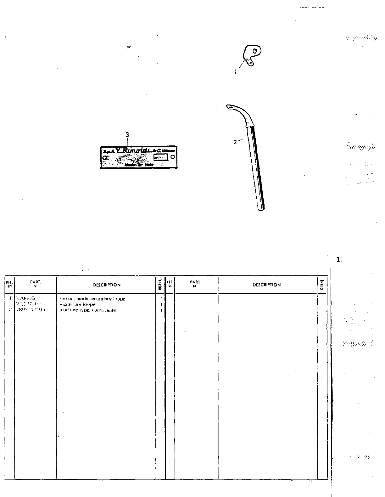
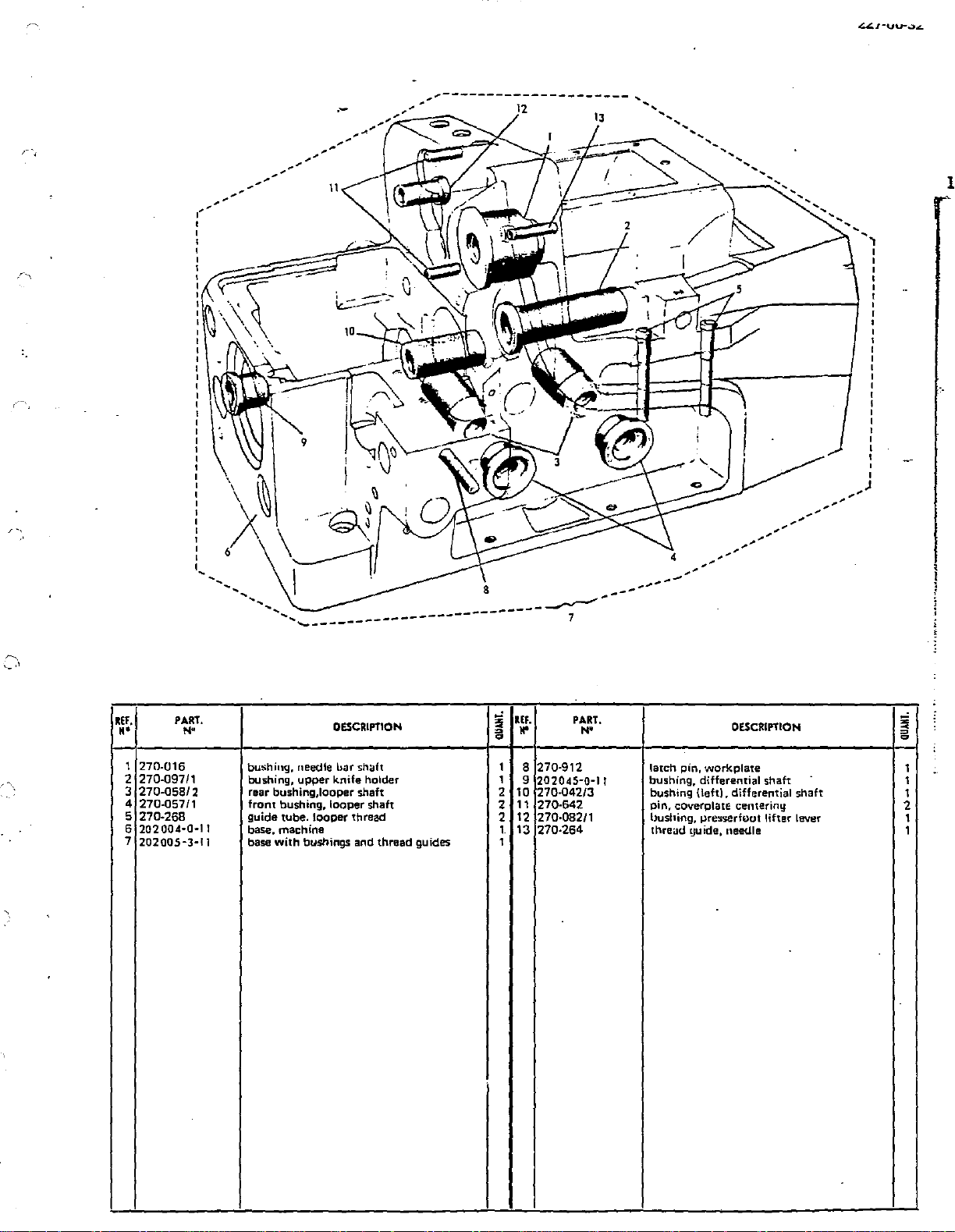
1
270-016
2 270-09711
3
270-05812
4 270-05711
5
270-268
6
202004·0·11
7
202005-3·11
PART.
N•
IEF.
OESCRIPT10N
bushing, needle hilr shaft 1 B
bushing,
rear bushing,looper
front
guide
base, rnachine
base
upper
bushing.
tube.
with
bushings and
knife
looper
looper
holder 1
shaft
shaft
thread
thread
guides
s
a
2
2
2
1
1
..
10
11
12
13
9
PART.
N'
270-912
202045·0·11
270-042/3
270-642
270-082/1 hushing, presserfuut lifter lever
270-264
latch pin,
bushing, differential
bushing
pin,
coverplate
thread
OESCRIPTION
work
plate
{left), differential
guide, needle
shaft
centeriny
shaft
s
~
=
1
1
1
2
1
1
Page 9
.-
20
IS
2
-~
/ '
' '
33
'
'
'
'
36----1
'
,/
'
'
'
'
'
15
'
'
22
IEF.
..
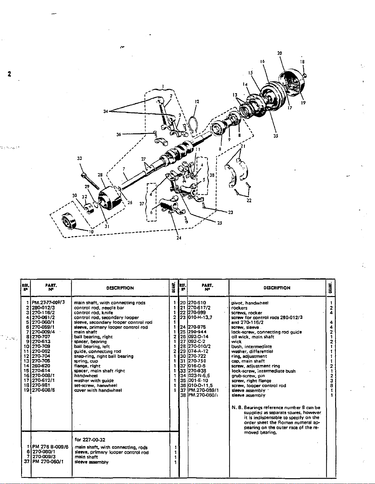
1 PM.27·n·009/3
2
3 270-116/2 control rod, knife
4 270-061/2 control
5 270-060/1
6 270-059/1 steeve,
7
a
··:.
9
10
11
12
13
14
15
16
17 270-612/1 washer
1a
19 270-608/5 cover
37
PART,
N'
280-012/3
270-009/4
270·707
270·613
270-709 ball bearing, left
270-062 guide,
270-704 snao-ring, right ball bearing
270-705
260-620 flange, right
270-614
270-00a/1 handwheel
270-9a1
1
PM
276
6 270:060/1
7
270-009/3
PM
B-009/6
270-060/1
main
control rod, needle bar
sleeve, secondary looper control rod
main
ball bearing, right
spacer, bearing
sr.•ring,
spacer, main shaft right
set~rew,
for
main shaft. with connecting. rods
slnve,
main
sleeve assembly
DESCRIPTION
shaft,
with
connecting rods
rod,
secondary
primary
shaft
connecting
cup
with
guide
hanwheel
with
handwheel
227-00-32
primary looper control rod
shaft
looper
looper control rod
rod
z
llf.
"'
~
..
~
1
20
21
1
1
22
73
2
1
24
1
1 25
2 26
1
27
1
28
29
2
30
1
1
31
37
1
1
33
34
1
1
35
1
36
1 37 PM.271J.059/1
38
1
1
1
1
PART.
N•
270·510 pivot, handwheel
270·617/2
270-999
010-H-13,7
270-975
290·944
092-D-14
092·C·2
270-01012 bush, intermediate
074-A·12 washer, differential
270-722 ring, adjustment
270-750 cap, main shaft
016-D-5 screw, adjustment ring
270-938 lock-screw, intermediate bush
023-N-5.5 grub-screw, pin
001-E-10
01
0-0·11,5
PM.270-060/o sleeve assembly 1
·
rockers
screws.
for control
screw
and 270-116/2 4
screw, sleeve 4
lock-screw, connecting rod guide
oil
wick,
wick
screw, right flange
screw, looper control rod
sleeve assembly ·
N. B. Beatings reference number B can
supplied as separate spares, however
it is
order sheet the A oman numeral
pearing
moved bearing.
DESCRIPTION
rocker
rods
2~0.01213
main. shaft 1
indisQensable to specify
on
the outer race
of
on
the
ap·
there·
be
•I
1
2
4
2
2
1
1
1
1
2
1
2
3
a
1
---
--·
Page 10

.-
'\
<:J
;"
'""
'1r
3
11
82
0
,
9 1 3 /
57
85
6
21
23
L
L/
2•
s
2
~,[I
16
,b.
IS
·:.
Rlf.
••
PART,
N•
DESCRIPTION
-~~
.~·~"~-'t'
........
~~~·-~~
55
,_,
IEF.
;::
z
H'
~
PART.
N'
61
'J!.
I 69
ti'
2
r;
DESCRIPTION
~
;;:
1
PM.270-049/1
27-27-051 feed dog, rear 1 48
2
3 270-977
4 270-640/3
5
092-B-1
6
270-937/1 .
7
27·27·052 feed dog, chaining
8
27U-b11/1 eccentric, feed dog lifter
9 270-979
10 070-M-4,5
11
270-035
12 !1030-06
13
270-048
14
073-C-8
15 270-054
16 071-M-5,5
17
279-047/2
18
070-F-4
19
057-F-4
20 270-975
21
270-039
22 270-7391
23
071·H·5
24
270-036/1
25 270-935
26
026·C·7
-27
PM.270-038/3
28
270-040
29 270-031/1
30 092-D-6 oil
31
092-D-12 oil
270-041/1
32
33
250-471
017-E-11
34
039-H-9
3S.
j6
064-F·5
37 270-992
J8
270-287/1
39 073-A-8
40 PM.270-562/2 lever,
41
270-28811
42
270-567
065·0-6
43
44
270-568
45
270-702
46
270-703
,5
assembly,
screw,
guide
oil
securing screw, differential eccentric
securing screw,link
washer,
bush.
collar
link,
washer,
pin,
washer,
guide
washer,
nut
screw,
shaft,
securing
washer.
sliding
counter-washer
screw,
complete
yoke,
pin.
rear
screw,
securing
screw,
washer,
screw,
upper
washer,
stop
sector
washer,
knurled
snap
needle
differential
attach
block,
wick
for
wick,
wick,
right
differential
differential
differential
pin
differential
diff.
ratio
segment,
diff.
ratio
pin
270-054
segment
differential
pin
differential
block,
counter-washer
adjustable
connecting
fork
yoke
dowel
rear
pivot,
differential
yoke
screw,
differential
segment
differential
sector
differential
complete
with
setting
knurled
knob,
ring 1
roller
bearing cage
slide
rear feed dog 1
differential
links
feed
slide
feed slide
segment
increase
ratio
pin
eccentric
differential
segment
segment
drive
shaft
marks
segment
increase
shaft
eccentric
control
assembly
diff.
eccentric
for
differential
rod
pivot
adjustable
differential
knob
lever lock
shaft
1 47 270-037/3
270-984
49
070-B-3
023-N-5,5 securing screw, pin 1
1 50
4
51
270-735 eccentric regulation
1
PM.270-045/2
52
270-033/1
1 53
54
1
270-980
1 55 270-943
56
270-034
2
1 57 005-L-11 securing screw for guide
1 58 270-997
1 59 270-566/1
1
092-D-4 oil
60
1
61
270-978
1 62 27-27·050
1
290-700
63
1 64 270-736/3
1
270-738
65
001A·2,5
1 66
1 67 270-729
279-249/1
1
68
1
69
270-250/2
1
70
270-253
71
1
004-L-7
1 72 PM.270-732/3
1
73
270-734
74
1
270·032/3
1 75 004-P-6
1
76
270-928
1
77
270-929
1 78 270-747
1 79
007-C-11
1
80
023-E-12
1
270-595
81
2 82 270-717
2 83 270·927
1
84
270-915 plu·g,
2 85 Olj2-D·11
1
86
092-D-23
87
270-594
1
1 A 270-046/3
1 B
270-038/3
1 c 279-733/1
D
270-732.'3
'
rod, differential
screw,
feed
washer, feed lever
attachment,
link,
securing screw, differential link
grub-screw,
bush
screw,
control
securing
front
snap-ring
shank,
soring,
screw
set-screw
shield
rubber
gasket,
securing
housing
flat
plate,
securing
grub-screw,
lock-screw,
gib,
screw,
set-screw.
gasket,
collar,
screw,
oil
oil
gasket
slide
segment
slide,
stitch
for
227-00-32
lever 1
differential
differential
securing
for
differential
difierential
lever.
wick,
spring
eccentric
wick
wick
for
differential
differential
screw,
feed
dog
for
pushbutton
pushbutton
pushbutton
guard
for
slide
guide
screw,
and
cam
differential
screw,
for
for
slide
collar
eccentric
differential
differential
collar
differential
differential
for
differential
stLtch
length
len~;~th
eccentnc
control
segment
slide
pushbutton
slide
control
link
front
feed
feed
dogs
guard
stitch
length
mechanism
cursor
plate
eccentric
grub-screw
control
collar
pinion
adjustment
adjustment
eccentric
cam
lever
segment
dog
slide
lever
bore
cam
eccentric
cursor
1
1
1
1
1
1
1
1
2 I
2 I
1
1
1
1
1
1
1
1
1
1
1
1
2
1
1
1
2
2
2
1
2
1
1
1
1
1
1
1
1
1
1
1
,
i
'
Page 11
4
.-
r
?-
·.···
Rlf.
••
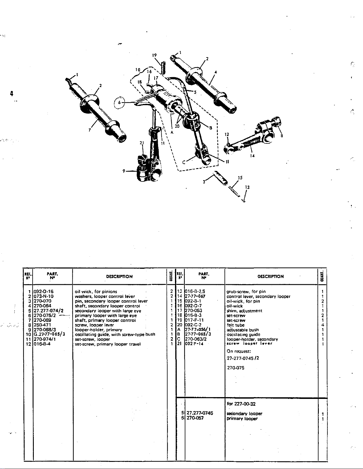
1
092·0·16
2 073-N-10
3
270·070
4 270-064
5
27.277-074/2
6 270-Q75/2
7 270-Q69
8 250·471
9
270-068/3
10
G.27-77·065/l
11
270-97411
12
016·8·4
PART.
N'
DESCRIPTION
oil
wick,
for
looper
looper
primary
pinions
looper
lever
primary
washers, looper
pin, secondary looper
shaft,' secondary looper
secondary
·~-
primary
shaft,
screw, looper
looper-holder;
oscillating guide,
set-screw, looper
·set-screw, primary looper travel
control
control
with
large
with
large eye
control
with
screw-type bush
leVer
control
eye
lever
s
,.Ef.
a
K'
2 13 16·8·2.5
2 14 7-77·067
1
15
I
16
1 17 70-053
1
18
1
19
2 20 092-C-2
I A 27-77-0SIJ/1
1 8
2 c 270-063/2
21
I
PART.
N•
92·8·1
2·0·7
15·8·3
17-F-11
27·77·065/3
002F·14
~
A"".
3'
"-.}<
grub-screw,
control lever, secondary looper
oil-wick,
oil-wick
shim,
set-screw
set-screw
felt
adjustable
oscillating
looper-holder, secondary
screw
On reQuest:
27-277-0745/2
270-075
IS
l
'·
for·pin
adjustment
tube
bush
guide
looper
14
DESCRIPTION
for
pin
l•ver
~
I
1
2
1
I
2
1
4
I
1
I
I
for 227-QQ.32
5127.277-0745
6 270.057
seCondary
t:H"imary
looper
looper
Page 12
.-
a::.·-6
227-00-32
REf.
H'
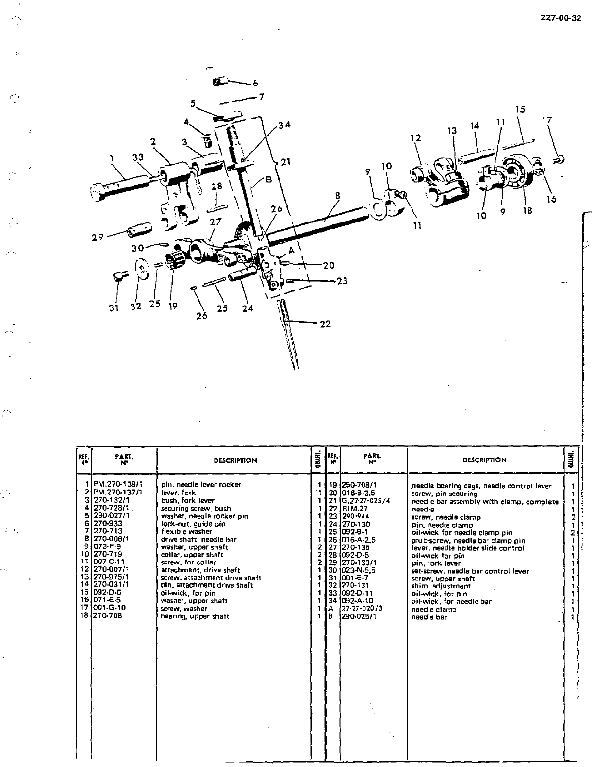
1 PM.27Q-138/1
2 PM.270-137/1
3 270-132/1
4 270-728/1
5
6 270-933
7 270-713
8
9 073-F-9
10
11
12
13
14
15 092-D-6
16
17
18
PA.kT.
N"
290-027/1
270-006/1
270-719
007-C-11
270-007/1
270-975/1
270-031/1
071-E-5
001-G-10
270-708
DESCRIPTION
pin, needle lever rocker
lever, fork
bush. fork lever 1
securing screw. bush 1
washer, needle rocker pin
lock·nut, guide pin
flexible washer
drive shaft, needle bar 1
washer, upper
collar, upper shaft
screw. for
attachment, drive shaft 1
screw. attachment drive shaft 1
pin, attachment drive shaft
oil-wick,
washer,
screw, washer
bearing,
collar
for
upper
upper
pin
shah
shaft
shaft
~
a
=
'1
lEF.
II'
1
19 250-708/1
20 016-B-2.5
21
G.27·27-025/4
22 RIM.27
290-944
1
23
1
24 270-130
1
25 092-B-1
26
016-A-2,5
2
27
270-135
2
28 092-D-5
2
29 270-133/1
30
023-N-5,5
31
001-E-7
,
270-131
32
1
33 092-D-11
1
34
092·A-10
27·27-020/3
1
A
1
B 290-025/1
PART.
N'
DESCRIPTION
.needle bearing cage, needle
screw,
pin
needle bar assembly with clamp,
needle
screw, needle clamp
pin, needle clamp
oil-wick for needle clamp pin
grub-screw,
lever, needle
oil-wick for pin
pin, fork lever
set-screw, needle bar control lever
screw. upper shaft
shim,
oil-wick,
oil-wick,
needle clamp
needle
securing
needle
holder
adjustment
for
pm
for
needle bar
bar
bar
clamp pin
slide
control
control
lever
complete
I
!
!
-'
;!;
= 0
1
1
1
1
2
1
2
I
1
1
1
1
1
,
1
1
1
1
Page 13

.-
6
7
9
. -
15
~
3
/33
A
1_/-
-~
13
·~~ia
"
32
----
-~::--·;
,·:~
I
---
--
-''SII,'
'29
-
'
I
,/'Y
'
fl
\ y·
~'I
.
,\
""._
20
',
9~1
25
~
26
IEF.
"'
1 27!l-102
2
270·096/1
3 27'77·112
4
092·0·5
5 128·111
6 271l-987
7
270.099
8 271l-103
9
073·F·9
10
270·719
11
007·C·11
12
270·108/1
13
270.098
14
092-C-2
15
092·0·9
16 250-471
PART.
N'
DESCRIPTION
pin,
upper
knife
upper
knife holder
upper
knife. serrated
oil.-wick
trimming guard,
securing screw,
block,
upper
lock-pawl,
washer, upper knife holder
collar,
upper
screw,
upper
pin,
yoke
yoke
attachment
oil•wick
oil-wick
upper
screw,
holder
upper
upper
knife
holder
upper
knife
knife holder
knife holder collar
attachment
for
yoke
for
attachment
knife holder
knife lever
knife
knife
pin
!2
kEf.
~
..
=
a
1 17
1 18
19
1
1
20 270·105
1
21
1
22
1
23
1 24
1 25
1 25
1 27
1
28
1 29 04-A-5
2
30
1 31 27.77·228
1
32 PM.271l-104/1
33
PART.
N•
007·P·10
064L•5
271l-104
277·113
271l-100
271l-106
003-L·12
wo-101
70-F-4
~;0~77
28·8·5
27.77·227
128·110
3
276
6·112
DESCRIPTION
set-screw, lower knife
washer,
fbr
lower
pin,
lower
spring, lower knife
pressure pin, lower knife
securing screw, lower knife holder
bushing, lower knife guide
washer,
screw, bushing
screw, upper knife holder
securing screw, angle
brace-plate, rear needle guard
angle stop, front needle guard_
knife
trimming
for
upper
pin
knife
holder
lower
knife
knife
for
bushing
holder. lower
guard
227-0il-32
knife
holder
upper
stop
knife
;;'
~
=
a
. '
1
1
1
1
1
1
1
1
1
1
1
1
1
1
1
1
I
1
-
Page 14

·.·:
r--------
I
1
,
23
~28
13
----
27
~~-
---
---
--
---
--
--
6
--
r-------,.
I I
I I
I
J-
I
I I
--:----
~------------------,
:
21
:
tJ~IB
I
I I
I I
------------J
12
lJ--16
,----......._19
l
~~25
L------------------~
I I
I I
I I
1
~~s:
I I
I I
' '
5
r-----··--------,
I I
:
I I
I I
I
\
~·.:
·~:
:
35
L--------------~
7
8
I
141
~37
~361
:
r·
I
REF.
••
10
1 1
12 G 27-778-076/1
13
14
15
16
17
34
35
36
37
38
PART.
N"
I
270.077
2.
270.081/1
3
270.083
092-C-2
4
5
PM270-085/1
6
270.087/1
7
270-985
8
2/0-08911
270-714
9
270-701 snap-ring 1
27-778·076/1
PM27.
778-076/1
270.085/1
270.091
004-L·B
001-~-4.3
G27.26·181/1
27.26-184/1
27.77-183
004-L-9 screw.
27.26-114/1
pin,
pressertoot
shaft,
presserfoot
bushing,
oil-wick
stop-pin,
lever,
presserfoot
screw,
spring,
snap-ring,
presserfoot
presserfoot
coupling,
stop-pin,
lock-ring, for
screw,
screw
for
227-00-32
presserfoot
shoe
presserfoot
chaming
needle
DESCRIPTION
presserfoot
lever
stroke
presserfoot
presserfoot
presserfoot
arm
arm
presserfoot
presserfoot
item
presserfoot
assembly
plate
presserfoot
plate
arm
lifter
lever
lifter
lever
shaft
adjustment
lifter
lifter
lever
lifter
lever 1
lifter lever
assembly
lifter lever 1
lifter lever travel
14
chaining
chaining finger
shaft
finger
-'
REf.
=
<
..
= =
0
1
18
1
19
1
20
4
21
1
22
1
23
1
24
25 G 27.277-181
1
26
27
1
28
1
29
30
1
31
1
32
1
33
1
1
1
1
1
1
PART.
N"
27.77-196
212
68-191
27-277-109/1
27.26·184
270-188
27.01 P-40311
27.26-186
27.277-114
27.277-10711
270-936/2
270-934/2
092-D-11 oil-wick 1
032-L·1C,5
CM
270-081,'1
270-073
bracket,
chaining
needle
shoe, presserfoot
chain
screw,
angle stop presserfoot 1
presserfoot
needle
needle
screw,
screw,
screw,
shaft,
tube,
protection
DESCRIPTION
presserfoot
finger,
guard, rear 1
cutter
angle
plate
guard.
front
rear
needle
presserfoot
pressertoot
mounting
assembly
for
narrow
front
needle
needle
plate
arm,
bight
guard
guard
securing
complete
~
0
1
1
1
1
1
1
1
1
1
1
2
1
1
---
Page 15

.-
er-·9
so_..!
'\\'-'
~6~-J~.
\
67
'
J\18
!\
\
~
~·
~·
5 f"""""
3
r6
64
......-r
70
. 8
·\·
30----
REF.
·"'
2 007-H-25 screw;
3 PM.27-27•205/3 cover, with
4 270-241/2 oil-cap,
5 270-965/2
6 270-983
7 PM.270-218/2 hinge assembly with guide tubes
8 007-R-7,5 screw. securing oil-cap plate
9
10 270-246
11
12
13
14 270-094 lever, presserfoot locking
15 270-701
16 270-086
17
18
19 270-993 set-screw
20
21
22
23
24
25
26
27
28
29
30
31
32
33
34
PART.
N•
I PM.270-208/3 side cover, with bushing
.270-245/4 oil-cap plate
G
270-Q93/1 cap, spring adjustment
032-F-9,5
605-412
270-078
2701·P·092
270-995
270-066/2
270-303
026-E-10 screw, seal
026·C-7
270-247/1
PM.270-095/3 shaft, pressurefoot pressure
G.270080/1 release
270-248/1
270-940
PM.270-210/3
270-972
270-730/2 screw,
270-220/1
PM.270-217/2 cover,
'\
\..~:_
packing ring, oil-cap
screw, cover securing
oil-cap plate gaSket ·
set·screw, stop cam
stOp cam
snap-ring
spring, presserfoot release rod
Pin,
spring. presserfoot pressure
screw,
plug,
nipple,
screw, splash guard securing
splash quard
plug,
plug,
work-plate
screw-bolt,
pin,
~.
... ) 26
'4\
DESCRIPTION.
top
cover
thread
With
presserfoot release lever
top
looper
cover
rod,
seal
screw
plug
front
looper
take-up bushing
window
cover securing
bushing
plug
securing
pressertoot
assembly
machine
cover
assembly
plate
and take•up
;i
REF.
~
K'
=
0
1
35
1
36
37
1
1
36
1
39
40
1
41
1
42
7
43
1
44
1
45
1
1
46
47
1
48
1
49
1
1
so
51
1
52 01205/A
1
53
1
54
2
55
2
1
56
57 270-619
1
58 270-624
2
59
1
60
1
61
1
1
52
63
1
64
1
1
65
1
66
1
67
1
68
69
\0
25
PART.
N•
007-F-14
270-221
054-0-4
270-226
G.270-242/3
028-E-10
270-212
001-0-6
001-0·4,5
270-718
017-E-4,5
270-030
270-973
270-715
270-129/1
270-73111
270-231
270-913
270-214
057-E-4
005-M-10
270-623/1
001-0-10
G.270-216/2
270-030/2
270-175
270-174
290-923
270-090/1
270-110
PM.270-301
016E
5.5
~;gm
31
_____
:~
............
_
'
'
DESCRIPTION
screw,
cover
spring, front cover
nut, retaining
screw, front cover securing
plate, complete with filters,
screw, bqttom plate securing
spring, workplate latch
screw, spring securing
screw, spring securing
collar, workplate pin
screw, collar
plug, differential shaft seal
screw-bolt,
set-screw
cap,
plug,
gasket
screw,
pin,
set-screw, side cover
nut,
screw,.side flange,
flange,
gasket, sealing disc
sealing disc
screw,
cover
screw, plug
nameplate,
nameplate,
set-screw, tie-rod
block,
tie-rod
splashguard assembly
screw
~:oo
OSit~T
machine assembly, short
for
guide
front
adjustment
pin
attachment
front
set-screw
left
sealing disc
plate
tie-rod
braclcet
WI
cover
plate
cover
plate
side
assembly,
front
cover
tensioning disc housing
left
cap
seal
securing
plate
front
plate
tubes
270-093/1
cover
-
~
~
a
1
1
1
1
1
4'
1 :
·1
1
1
2
1
1
1
1
2
1
3
1
1
1
3
1
1
1
2
1
1
1
1
1
1
1
1
I
l
;
Page 16

f1P
31
~t'1
30-.··?-
._p
25
26
<
---.C.
~
e:;;:..
~
·~.-
:.;..~
-
..
;·1
i
REF.
••
1 270-941
2 PM270-263/1
3 270-27413
4
5
6 270-265/1
7
8 270-268
9 780220-0-00
10
11
12
13
14
15
16
9
29
PART.
N•
270-264
270-265
270-266
270-26912
004
L-8
270.270/2
004
A-3.2
270.276/1
27.277-2751
032-A-6
780232-0-00
270-271
screw,
tube.
take-up,
needle
bush,
bush,
bush.
tube.
machme
take-up,
screw,
take-up,
screw.
bracket,
thread
screw,
for
227-00-32
machine
thread
thread
needle
needle
thread
upper
upper
lower
lower
type
pnmary
take-up
secondary
bracket
looper
guide,
thread
type
guide
DESCRIPTlON
guide
thread
thread
guide
thread
guide
thread
guide
thread
guide
thread
guide
nameplate
looper
securing
looper
securing
secondary
guide
nameplate
tube
securing
guide
looper
secunng
REF.
~
,.
=
~
1 17
18 270-233
1
1 19
1
20
21
2
2
22
23
2
24
2
1
25
1
26
27 27
28
29
30
31
PART.
N•
272-232:1
202558-2-00
603-031
270-230
270-232/2
004
\J-5.5
202556-0-00
270-232"1
250-031
27-253
016
E-2,5
27
00-2714
:;
:u
.27-262
004
P-4,5
"2
spring,
primary
bushing,
nut,
d1sc,
pm,
sprrng,
screw,needle
cup,
~rmg
disc
thread
,;ccew
thread
needle
screw
upper
tension
tension
tens1on
needle
tension
needle
tens10n
gUide
gu1de
thread
DESCRIPTION
looper
tenSIOn
adjustmg
screw
take-up
diSC
take-up
securing
assembly
2
4
4
6
4
1
2
4
1
2
1
1
1
1
1
I
l
!
!
:
Page 17

-----------------------
-----------
·-
-------~~:::::::::;:3:::::\l
i~\
1
------
------
12
...
~J
--
...
""
...
,"
-,
1
1
I
I i I I A E
I I 6 I - - •
l
L---------1~:
___
F:
_.J
2..
_______
-ll
___
\'~\
3 c H M
----~=:;;:.
1}~1'\/~::::~
_':.-::= / ,'
·:::---
, 45
[ :
--
"
..,.,.
9~
10
KEF.
••
I
I
I I 1 I
\
I
I 1
I
\
I
I 1 1
I
\ I I
1 1 I
I
17
_.@)
18
I
I : : 1
I 1 I I
I 1
\ I < 1
I 1 1 1
I
43
M('/23
;'
22 I I
16
-Q
= 24__..(l 1
,.
II
~
,..
I ,
\::::::,
\ A I l
\ \ :
PART.
N'
\
1 1 ,
\ l
I 1
\
I 1
I 1
I I 1
1 " ,
\ ___________
26
1 54
1\
31
~:.-::.·:::::.=.--~-=-·::::.~-:::.~-----~
;i
DESCRIPTION
Rtf.
~
~
••
g
PART.
I I
1
i
1
3
38
14:
41
,
1 I
1 I
! I 1
1
1 1 :
'"--~35~-
/33
.
I
N•
-t
_41
T
46
DESCRiPTION
I
;;
~
=
g
1
34
1 G.270·816/1 oil
2 G.633·833/1
3
PM
.270-816/1
4 633-812 screw
5 PM.633-817/1 cover
6 633-818/1 washer
7 633-71111 gasket 2
.;.
8 270-82411
9 270-823/1
10
633-708
633-707
11
12
039-G-10
13
270-810/2
14
633-959/1 oil level
270-808/1
15
633-842
16
17
270-81111
18
270-946
19
270-947
20
065·L·5
21
059-G-6
270-83111
22
23
270-836
017-H-12
24
007-l·
25
26
27
28
29
30
31
32
33
20
633-966
270-82811 disc
270-996/2
270-827/1
633·925
G.270·996/2
270-00112
205520·5-00
pump
gear assembly
pump
worm
shaft
flexible
cup
screw,
pulley, oil pump 1 46 028-E-10
gasket
tube
pin
gasket
gasket
washer
nut
tube
felt
grub..screw 1 a 633-822/2
screw 1 c 533·819
gasket
plug
felt
spacer
plug,
oil
oil
assembly
unit
pin
spring
pulley
securing 1
window
pad
disc
oil
sump
sump
pump
and sump assembly
complete
270:966/1
1
35
G.270·646 oil
1
36
PM.27Q-645/1
4
37
057-A-3
1
38
270-650
1
270-551
39
40
270·73411
41
1
270-652
1
1 43
533·82611
1 44
270·645
45
016·8·2.5
1
1
1
2
2
2
2
2
54
270-432/1
1
270-430
55
1 A 633-82112
1
D 633-833
1
E
633-81811
F
533-834/1
1'
1
G 270-816/1
1 H
633·814
1
L 533·813
1 M
670-702
1
gasket
distributor
oil distributor
nut
valve
gasket
flexible
junction tube
coupling
pointer, oil disttibutor
grub-screw,
screw
current
rubber
gear
wheel
gear
wheel
gear
plate,
gear
plate,
washer,
drive
shaft
housing,
roller
roller
seal ring
washer
tube,
pointer
plug
gasket
pin
side
inner
inner
pump
housing
housil"'g
assembly
oil
pump
1
1
1
2
1
1
1
1
2
1
1
2
1
1
4
1
1
1
1
1
1
1
1
2
Page 18

.-
,-
1
22
\\
-~--~
18
227-00-32
16
'
I
'
'
24
REF.
••
1
2
3 059-A-5
4
5
6
7 270-701
8
9
10
,
12
13
14
15
16
17
18 G .270-005/3
19
20
21
22
PART.
N'
G.270·583
270.585
270-583
270-459
270·557
270·558
270-552
270-004
PM.270-005/3
270-588
058-M·10
067-H·10
270·971
051-L-10
PM.1159
270-58611
270·584
065·L·6
059-H-6
17'-......~
z
DESCRIPTION
tie-rod assembly, presserfoot lifter lever 1
coupling,
lock-nut,
rod,
loc::k·screw,
coupling, presserfoot lifter lever 1
snap-rings
pin,
bushing,
rubber
bearing
guard,
nut,
washer. machine bearing plate
screw, machine bearing plate
nut,
chain
machine
lever, presserfoot
pivot, presserfoot
washer 3
nut,
presserfoot
lifter
presserfoot
flywheel
for
coupling
upper
mounts,
plate,
flywheel
machine bearing screw
machine
with
hook
bearing
presserfoot lifter lever pivot
lever
lifter
plate
machine
with
plate
plate
lifter lever
tie·rod
lever 1
guard
pins
mounting
lifter
lifter lever
bolt
upper
~
-
=
a
tl
;.
'
~~
lEF.
..
1
23
270.558
2
24
270.590/1
270.590/2
7
001-G-10
25
270.589/1
26
3
2
,
4
1
1
8
4
4
4
1
1
1
1
1
PART.
N•
25
ON REQUEST
pin
waste
chute
chute
chute
liang·
(left)
chute
-short
waste
screw, waste
waste
DESCRIPTION
right)
securing
~
=
a
,
1
,
3
,
I
I
I
'
Page 19

r
::=-=..:..
1
;__-=---=-:
117 - • "-
I
I
1s
13
19
11
==
;aj-
16
14 I
20\J
-l
i
'
40
42
41
12
37
3
j"~~~
9
7
rr,-
1
22
19
i1
-----
23
~
rs
:----::;--,
,
/~
6
2
25
I
3
29{;~;
__
_]_a___
26 1
---
39
33
n~
~
••
RIF.
1
2
3
4
5
6
7 001-G-.12
8 001-G-10
9
10
11
12
13
14
15
16 PM 260·13411
17 PM 26(). 133/1
18 PM
19
20
21
22
23
24
25
26
27
28
29
N'
DISEGNO
AS.2727-140
AS.260-140
605-937
605-980
32727-157
01141
26().142
1146
:3260-137
25().143
25().130
250-137
260·140
260·13511
016-=-5
PM
250·148/1
270.158/1
2727-137
569
·;s
20 x 3o
PM
91().914
053-H-8
910-964
910-93411
3
910-914/1
OENOMINAZIONE
SUPPLIED
thread
thread
bracket
locl<·sctew.
bar
base, thread
screw, rod securing
screw,
plate,
pin.
frame.
upright,
upright,
rod,
connector·piece,
rod,
rod,
rod,
grub-screw
sustaining
bar.
rod,
pad,
screw,
pedal
mit,
screw,
hase.
pedal
WITH
stand assembly
stand
assembly
sustaining
rhreud
thread
threml
thre<ld gu•de
thread
thread
threud
thread
pedal
with
smnd
plate
securing
thret:~d
spool
spool
thread
guide
main
lower
main
upper
guide
rod
guide
gu•de
rod.
thread
guide
guide
spool
thread
swntl
sh<~rp
oedal
iJSsemhly comJJiete
HEAD
ONLY
complete
thread
assembly
guide
susmining
securing
guilfe
rod
rod
~lowed
upuen
~
~
=
Q
1
1 31
1
2
1
.1
1
1 37
1
4
1
1 41
1
1
1
1
1
1
10
1
1
1
4
2
1
2
2
1
1
llf.
"'
30
49012
910·143
32
569
1146
33
34
001·:3·10
270·157
35
016·F·5
36
270·158/1
605·937
38
605-980
39
40
1145
910·144
42 G 497
N
DISEGNO
'
DENOMINAZIONE
SUPPLIED
thread
upright,
pad,
pin,
cap-screw
rod,
grub·Ererew 1
h~u.
h•·acket,
lock-screw
lock·nut,
upnght,
thread
WITH
STAND
spool
main
thread
spool
thread
spool
thread
guide
thre::td
guide
rod
threllll
thread
top
sec lion
gu•de assembly 1
suslilining
guide
rod
sus.twning
guide
suswinrng 4
bur
~
=
"
Q
I
I
i
'
'
'
1
2
5
5
5
1
1
1
2
2
I
I
'
-·-~
I
Page 20

a
0
\
15.
\
6
1A
i.e
·-----=\1
'
10
I
----·
'
13
227-00-32
)
~--~
~111
-
IEF.
••
1
VR.504
2
1175
3
280-155
4
R1M.27
5
115112
6
533-742
7
8
641-LY-743
9
1156/1
1158
PART.
N'
-
-
o~l.
1
quart
machine
vee·belt
needle,
RIM.27
screwdriver
hex.
wrench.
pincers,
threadmg
hex.
wrench
wrench,
double-ended
)""'t
19
can
cover
-
1/8''.
3/32"
-
...........
8
,17
DESCRIPTION
for
270-715
(
4
/
12
1
!
~
~
1
1
1
5 13
1
1 15
1
1
1
IEF.
••
10
11
12
14
16
17
18
19
PART.
"'
270-741
539-M-745
277-113
27
77·112
01160/2
270·745
0116112
270-743
2i0·431
290-746
pipe-wrench,
wrench
for
kn1fe.
lower
kn:.'e,
upper
screwdriver
hex. wrench,
screwdriver
hex.
wrench,
power
cable
h@l{,
wrenc:h
On
reQuest:
270-SiS/1
DESCRIPTION
9/32"
oil
sump
9/32"
5/64"
and
plug
1/16"
plug
fo•
nl!'edles
Tab.
75
z
c
~
~
1
1
1
1
1
1
1
1
1
1
-
'
;
Page 21

t227-0!J.20'
14
B
~
6
·-
7
5
(21
16-
I
s~'LRLI1UrlJ£ac-~
····'
· ... : .
.~.....;·~-
-------~2
'
I
:1?
I~
[
_____
i--
1
I
I
19
I
oi''
c::r-:
.-
11
~-r
::__j
----;4--
---,
I
I
I
I
I
I
I
I
I
15
20
----··
REf.
·--
I-A
••
605-144
1
2 011
-lT
3
Q01G-12
4
605-143
5 605-723
6 605-937
7
605-380
8 G250 R-937"3
9
057
.C..-'3
27.77
w
11
001
C·5,5
,,
...
R-267
-----·
DESCRIPTION
ba;.
toP.
base
sc:-ew
uupnght
tapered
sieeve
bracket
knurled
head
e/a:;ric reel ::.ttmd
nut
gUide, ,.e,:;f':>rcing
screw
!>Crew
tape
·-
i·
=
~
1
1
1
1
2
1
4
1
1
1
1
REF.
H'
PM::7.-.7
1<
13
2.".7.77 F:.-134
14
2.'
.
15
;.7.'lG B-1?1
16
·:a.1256·0·G·J
1:
0~4
18
: .
.'.~
13
:104
:a
G?.7.:.7J
.,..S
21
PART.
N•
.'7-136
L-8
..,; P-0.11
G-3
F-181
2:Jx30
F-267
gur<fe.
remfcrc:ng
shce
lug,
ch:uning
!in!JP.I',
m<.~c!Hne,
screw
plate
•;crew
presserfoot,
M:rew.
pl.rle
c!mining
type
c..:omplete
~r,nne
securing
DESCRIPTION
t.Jpe,
complete
n.1mepline
~
• i
'
'
I
'
1
i
~
-
1
;
?.
--
Page 22

-----------~----
..
.-
a)
Identification numbers
1.
Every head
- class or sub-class number
- serial number
2. The class
3.
The
head serial
is
identified by:
and
sub-class
number
num~r
is
are engraved on the name-plate, on
engraved on a
HEAD IDENTIFICATION
I.
boss
on the
bottom
of
the
the
base
base
.
of
the machine.
II.
The machines depicted
following
1.
2. Differential
general characteristics:
Straight needle, system
can
be
TECHNICAL DATA
in
this catalogue are overedging machines with 2 needles, needle gauge
RIM
27/Fmb ·Thickness
regulated while machine
is
80
· 100.
running.
BY
MACHINE CLASS
3. Push-button stitch length adjustment.
Stitch length variable from 6
4.
5. Differential feed ratio: up
6. Width of bight: from
7. Speed: from 6000
to
3/16"
6500
to
30
stitches per inch.
to
3,5:1 and also up
to
5/16".
RPM,
depending on the tYpe of application and manufacture.
to
4:1.
8. Lubrication: by pump.
9. Motor: 1/3
HP
or 1/2
HP,
according
to
subclasses.
10. Outer dimensions of machine head: 12" x 9.3/4".
11. "''eight: approx. 45 lbs.
3/32",
with the
Page 23

a}
Positioning
After
motor
1.
Force-fit
2. Place machine head
the
of
head
is
mounted
four
INSTALLATION
I.
on stand, proceed as follows:
rubber
shock
absorber
on
table centering
the
pads
lower
on
to
holes in
the
the
AND
pins
head
TIMING
provided
on
the
on
the
machine
shock absorber pad pins.
head
bearing
plate
f'.
.•
b) Assembly
1.
Install driving belt as shown
2.
Check
on
pump
3.
Adjust
that
pulley,
belt
of
transmission
reverse
without
tension
of
driving
by
loosening
in
diagram
belt
slipping.
1.
rides firmly
motor
clamp
and
squarely
4. Level machine head by adjusting machine cradle bolts.
5. Tighten up machine cradle bolt lock·nuts.
c)
Filling lube oil sump (fig. 2)
Unscrew threaded cap
1.
Pour
in
2.
Check
3.
,
red lines .
Replace and tighten cap 'A'.
4.
Before starting
5.
1 and
through
'A:
3/4
pts Esso Standard Teressa
oil-window
up
the machine, the following
that
oil level
is
between
points
43
the
should
oil.
two
be lubricated:
- needle clamp guide rod
-
upper
looper bar
6.
Start
machine slowly. letting it idle for
gradually rev up from 1500 r.p.m.
about
5 minutes and
to
rated operating speed.
d)
Assembly and adjustment of sewing parts
Note: The operations described below are for machine timing
1.
Timing gauges required:
·
S.
.··-.
1686.00
·
S.
1555.00 for operation
2. Preliminary disassembly of:
·-Front
for
all
cover plate
operations
N.
except
4
operation 4 (fig. 4).
· Both thread take·ups of lower looper holder
·
Side Cover Plate (casing) of needle movement
· Upper plate with oil indicator cap
· Side plate protecting needle movement
· Main feed dog
Hg.
2
Page 24

3.
Setting
of needle (fig.
3).
-~
•
if
the
needle plate
be
centred
..
holes
of
the
the
distance between
surface of the needle plate
is
at
its highest point.
if
adjustment
move needle bar clamp up
S.1686.00
setting. Retighten screw A .
is
in
proper position,
for passage through
needle plate .
the
is
necessary, loosen screw A (fig.
as
indicated in
the
.-
needle _points and
is
11/32 inch when
or
down,
fig. 3 to
the
needles
resPective needle
using_
needle gauge
obtain the correct
the
must
the
needle
3}
top
and
~-~
·..--;
__
"""""
-~
i::
A
i
f
-.--·-·;.":":···.--
__
4. Setting primary looper (fig. 4
SETTING OF
fig. 4
Setting
angle
Slightly loosen screw 'D'
Place timing gauge S.1686.00 on milled surface
as
shown
in
fig.
5;
shift
lever C
has been
is
obtained.
Correct
timing table.
Firmly tighten up screw E
set
in
place
but
position can be checked by reference
and
turn
not
locked) until correct angle
(fig.
41.
loosen
mount looper height gauge 5.1555.00 on the primary looper shaft wi:
special
raise
5.1555.00.
slightly tighten screw E (fig. 4).
set thread guide bracket A by raising thread guide bracket to the
primary
retighten screws 8 and
remove looper height gauge 5.1555.00.
looper (which
HEIGHT
screw
E.
screw supplied with gauge as shown in
or
lower looper so
looper
shank.
that
its
point
contacts
E.
of
base
to
the
fig. 3
fig.
the
4.
upper
line
on
timing gaur-
top
of
th
...
Setting
the primary
When the primary
the
left and with
distance
be
If
tion axis. ln its
point
dle scarf.
Retighten
'between
as
indicated
adjustment
should pass 1
scr~w
in
IS
necessa;-y move lever C along its rota·
D
looper
looper
the
the
looper
fig. 6.
stroke
64"
in
has
needle
point
from left
from
relation
completed
in
its lowest position,
the
and
to
bottom
to
the
its stroke
the
needle should
right
of
the
needle:
looper
the
to
the
"·
A
nee-
llg. 5
" .
...
c
----
....
f
Page 25

---------
5.
Timing
Secondary Looper
fig. 6
If
adjustment
is
required, slightly loosen Screw 0 and push
wards, avoiding any change
Lock-screw
Recheck
Tighten up screws A and
Finally, make sure
D.
to
make sure the two loopers are crossing
B.
all
the assembly are moving
Note: To
~ownwards:
mcreased
Slightly
Slightly loosen screw
Adjust crossing
looper
tip
barely
set
the
remember
or
decreased.
loosen screw B.
rotating
passes
behind the
skimming
dimension 1
that
A.
of
secondary
the
secondary
primary
it.
Check distances given in figures 7-8 {see
timing
table).
Durin£ its left
ary looper should barely
in
the distance already fixed. Make sure
to
right
smoothly
motion
skim
and
smoothly.
1/32''
by doing
in Fig. 8,
this
rotate
the
dimensions
fever E
in
upwards
Fig. 7 will
and primary
so
that
its
looper
the
second-
the needle.·
fig. 1
the
complete looper assembly inwards or out-
all
parts move smoothly.
verify
all
the
other
settings.
or
be
6. Setting the needle guards (fig.
To
set
front
needle guard
With needles
Retighten screw
To
set
a~
their lowest position,
C.
rear needle guard
With needles in their lowest position,
Retighten screw
It
must
be checked
D.
break through impact with the primary looper.
of
the
machine and check
breaking
them.
If
this
slightly just above the shanks, where the
9)
A,
loosen screw
B.
loosen screw
that
when working,
that
is
not
fig.B
C.
set
front
needle guard so
D.
set
rear needle guard so
any
eventual slight bending
To
do
this, bend the needles slightly
the
primary looper. during its stroke from left
the case, the needle guards need
part
is
not
so hard. Check
that
that
to
it
touches
it
touches
of
the
be
positioned
that
the
needles.
needles
needles does
correctly
each needle
sponding plane of the front and rear needle guards.
Thread the needles, bringing them
pushing them slightly against rear needle guard
The thread
the
needle
must
run freely.
is
too
low and the thread
to
their lowest position and
B.
If
this
is
not
the
is
trapped
case it means
between needle
that
and needle guard.
~JOTE:
The
point
of
the
looper,
enter
the needle scarf
in
the lower portion.
left,
For very hard synthetic fabrics the needle
on the
front
needle guard.
in
its stroke from left to right,
in
its upper portion
and
must
must
in its
stroke
to
flex considerably
the
D
without
not
towards
to
right, passes
hv
operates
lia.
deflection.
cause
the
bending
in
9
them
inner
without
the
to
part
them
corre-
Page 26

7.
Mounting lower
trimmer
knife (fig. 10)
Mount guide block P on knife-holder with screw
Slide knife D into place.
The
cutting edge
Tighten.
With the needles in its lowest position, bring angle stop 0 close
washer G by tightening
Check
51
- With needles in its lowest position, bring guide block
P close up
tightening
After setting
trimmer
is applied between
Press
screw N firmly.
Pressure should be lightly
strong friction between
their
up
that
ightly tighten screw
knife, slacken screw
one
hardening.
of_
the
trimmer
screw
A.
up
knife holder C moves
N.
to
front
needle guard and lock it by
up
screw
a.
upper
trimmer
the
knives by spring M and pin
finger lightly against screw A and tighten up
the
knife
must
_
screw
F.
smoothly
knife touching lOwer
N.
The proper pressure
exerted
to
avoid generating
two knives resultating
Q.
be
flUsh
with
the
and adjust setting for required bight.
H.
in
·rear needle guard.
to
the needle guard, lock bushing L and
i
'I
i
~-~
;;
__
ie·
'~
«:""
\
N
.
:-.·
··.-:·
---~
8. Mounting and setting Feed Dogs (figures
Remove Plexiglass plate beneath work plate.
Mount rear feed dogs C and D (fig. 11) and match
With a small screwdriver pushed through the threaded holes on
the
screwdriver into
Mount the
Slacken screw
Adjust feed dog angle by rotating eccentric
.---~···
~
front
'
.~
-~'-
the
differential feed
A.
..
""
\;:_
..
~,
groove
on
the
dogE
tip of
11
and 12)
the
screw.
with screw G
B.
c ;
. ! D
--~s
~a"·-~-~-
~
.
•,
fig.
11
I
,,.
the
feed dog slides.
the
but
do not tigh;en it up fully
fig.
10
levers, tighten screw F slightly, inserting
(fig.
12).
fig.
12
The feed dog teeth visible through the needle plate should be absolutely flush with
When
the
feed dogs are
and
the
needle plate.
Feed dog C should
Lock
screw_s
F,
G,
9. Feed mechanism (fig.
Note: The machine heads illustrated in this catalogue are supplied with the feed mechanism already
type
of use to which they
If
feed mechanism adiustm8!"7
at
their highest position, there should be a clearance of 1,3 mm. between
at
the
front
be
lower than the
and
A.
131.
will
be
is
of
the
differential feed dog.
other
two.
put.
r~quired.
proceed
as
follows:
the_
latter.
set
the
for
teeth
the
Page 27

--------
------
1.
Inactivation
Slacken
of
differential
nut
high as it will
up
Tighten
nut
2. Setting differentiaTfeed
Slacken
Set
Lock
pin Q
nut
nut
at
B.
B.
Lower lever H against
3. Setting
differential feed for retia 3.5 : 1
Slacken
Set
Lock
nut
B.
pin Q in lowest positio·n.
nut
B.
Lower lever H against
4. Setting differential feed
Raise cursor C
------
feed:
8 using wrench A supplied
go.
B:
lower lever H against
_
for
ratio 2 : 1
highest position.
stop
G.
stop
G.
for
ratio 4 : 1
to
its highest position
- Proceed as for item 3
- The differential ratio can be changed
5. Setting negative differential feed·
Slacken
Set
Shift
nut
B.
pin
Qat
highest position.
cursor C in lowest position.
with
stop
F and lock knurled knob R manually.
on
slide-barS
w~ile
the
the
machine head, and
machine
is
in
operation
raise
pin
by
adjusting lever
Q on rear feed
E.
dog
lever
as
fig.
13
10.
Mounting
upper
Mount
upper
trimmer
trimmer
knife
knife
(fig. 14).
C on
knife
holder
block
Mount knife holder block D and trimming guards E and G with screw
F.
Trimming guard E should be very close to cutting
,'of knife
edge
When
trimmer
cutting
·trimmer knife by
For
this
slanting seat and
knife holder
Tighten
when
in
guard.
C.
knife
C is
edge should overlap
1/32".
adjustment,
knife
shift
holder
B.
up
screw F and check
lowest
position,
does
at
the
its
I owest
cutting
trimmer
block
that
not
touch
position,
edge
of
knife
A on
th~
the up-per
front
its
lower
in
its
upper
knife,
needle
fig.
F
14
Page 28

e)
Positioning and adjustment
of
presserfoot arm
{fig.
15).
Insert presserfaot
arm
shaft L
in
bus,b.ing
Con
which
Insert presserfoot arm shaft L with bushing C into hole
provided
Slide lever
Slide snapring F on
Set lifter
foot
Slightly tighten screw
With needle
ing
- Engage
When pedal
in
baseplate.
A and spring E on
lever A so
arm shaft L.
arm D
in
guide fork.
lifter lever A
to
shaft
L.
to
shaft
L.
that there
is
no
end·play
on
B.
at
highest position, insert presserfoot bear·
with
presserfoot lifting
is
depressed it should have a slight idle
foot
stroke before actuating presserfoot bearing arm
Adjust lifter lever
tion.
Check
movement
serfoot
below presserfoot
is
at
Tighten up screw
its
A,
by regulating screw
of
secondary
highest
bearing
position.
arm
B.
in
looper; the latter
This
undesirable
0,
on
side
cover.
base beneath
presserfoot
presser-
pedal.
D.
should
condition
the
not
bearing
lever, so
impinge
can
be
arm
that
on
presserfoot
prevented
is
hinged.
E.
~M
L
it lifts presserfoot to required posi·
chaining finger
by
adjusting eccentric
when
washer
pres-·
M,
f)
Adjustment
The
ment.
The moving part C should
needle guard
The cover plate can be shifted towards left
adjusting screw
Lock
g)
Adjustment
of
front
cover plate
front
cover plate should be closed before adjust·
or
the
lower knife holder.
{fig.
16).
not
interfere with the front
B.
nut
A.
of
needle thread takiHip
or
right
by
For making up very tough fabrics, needle thread take·up 270·274/2 should be shifted forwards, towards ope·
rater.
Page 29

ELECTRIC LUBRICATION CONTROL DEVICE (PRESSURE SWITCH)
.-
h) Disasoombly
-·
Take
down
- Remove screw
Slacken
Slip plastic
Remove
Screw
scrAINS previously removed.
Re-install
and
replacement
oil cup from baseplate and drain
by
which pressure switch bracket is
the
two
screws
tube
connecting pressure switch to rubber
bracket
down
and fix it
electric wire lugs, slip plastic
011
cup and
on
fill
of
pressu"'
the
electric wire terminal lugs.
to
new pressure switch.
with oil
as
switch
tube
instructed
out
oil.
mounted
into pressure switch and
on
page 11,
on
connection
par
c.
oil
cup_
off
the
pressure switch.
mount
switch on oil
cup
using
the
Replacement
Proceed as described under items 1 and 2 for replacement
Remove
Re-install rubber
Re-install oil
Electrical
- Plug cable
Nota: If
with
12
Mount
light terminal lugs.
Plug cable
of
pressu"'
rubber
cup
connection
to
current
no
light socket
V. connections, proceed as follows:
a Mignon
to
current
switch lamp
tube, remove lamp (bayonet cap)
tube.
replace pressure switch in position and fasten firmly to
and
fill
of
pressu"'
socket
is
socket
socket
with oil
provided on
pitch 13
as
instructed
switch
on
and insert plug
the
at
one
at
one
end
and
on
page 11, par c
Zafir
moton
at
other
motor
to
be
end
of a cable 4 • 5 inches long
and
to
the
above Mignon
of
pressure switch.
replace with new lamo.
end
of
cable in 12
connected,
but
socket
the
and
at
V.
voltage
the
light
at
011
the
other.
wah
~cr~w
socket
on
connection
other
connect
motor.
box
it
is provided
to
the
12 V.
~
.
Remove cover.
Using a screwdriver, turn indicator 8 in required direc-
tion !Turning towards
the rate
wards
of
flew
the
letter A, the rate of flow
the
letter C puched on
is
decreased, turning the indicator to-
is
increased).
the
plate,
fig.
IS
B
Page 30

.-
TIMING
T A B L E
MACHINE HEAD NUMBERS
227 .()().32
227-00-20
227.()1.()7
227-00-21
----
A
2,5<2,8
2,5<3
2,5<3
8
1,5 3,3<3,5
1,5
1,5
-
c
8,5
3,5
D
0,5
0,3
0,3 8,8
F
-
8,8
Page 31

,
a ·
Thre~umg
.-
II
- USE
I
(~
I
'
•
I
i
\
·~
..
'
\
'
\
\
'
~·
I
I
I
I
~
'\
I
I
I
I
~
~
'
\
-
/
I
'
I
I
I
I
227-o0-32
Page 32

b)
Needle change
1.
Switch
off
motor.
Depress motor'driving pedal
2.
3.
Set needle at
4.
Lower lever
Swing
5.
Slacken
6.
top
dea~
8 as far as it
·out presserfoot from
needle set-screw by
centre.
will
to
check
that machine
go
(fig. 19).
usual
working position.
one
half-turn using screw-
is
absolutely motionless.
driver 290-7 46.
7.
Remove
8.
Insert new needle.
The needle scarf should face
9.
r·
10.
towards
Using
needle touches
Retighten needle set-screw without· displacing
11.
le,
needle.
the
rear
needle guard. i.e.
the
rear
of
the
machine.
pincers supplied with machine kit, check
the
bonom
but do not apply excessive force.
of
the
hole.
the
that
need-
F
c)
Positioning and adJustment
1.
Check
that
presserfoot
Needle should pass between pressurefoot
r
2.
To
adjust presserfoot slacken screw
3.
Center presserfoot
4.
Presserfoot pressure
5.
led
knob
A.
Lock knob A by tightening up screw G with wrench 633-742.
6.
is
in
proper position
is
increased or slackened by loosening screw G with wrench
of
presserfoot (fig. 19)
in
proper position.
F.
shoe
and chaining finger.
and
tighten up screw
F.
fig. 19
633-742
and adjusting knur-
-~
d}
Tensioning discs adjustment
1.
Tighten tension discs just enough for even stitch formation.
2. Avoid over-tightening.
e)
Stitch length adjustment (fig. 13)
1. Slacken screw P using appropriate wrench.
2.
Depress pushbunon 0 and
3. Holding
pushbunon
0 firm,
turn
handwheel M until tip of pushbutton slips into
turn
handwheel M vigorously until indicator N shows
the
notch on
the
desired length on
the
regulator.
handwheel.
4. Tighten up screw P firmly.
f)
Seam width adjustment
Seam width can be adjusted within a very narrow range beyond which the needle plate must be changed.
To
vary seam width within the above narrow range, proceed as follows:
1.
Slacken screw N of lower knife holder (fig. 10).
2.
Slacken screw F (fig. 14).
Shift upper knife holder block A (fig. 14)
3.
4. Tighten up screw F
(fig.
14)
5. Lower knife holder should be checked and set
to
right
as
or
left until desired seam width
described
in
paragraph
d)
7.
is
obtained.
the
r
Page 33

g) Trouble due to incorrect handling
.-
of
machine
..
No.
1
2
3
TROUBLE
Uneven stitches
Feed
and Fabric
slipping sideways
Machine skipping
stitches
PROBABLE CAUSE
- Tension badly adjusted
- Thread take-ups incorrectly adjusted
- Wrong threading
- Yarns
- Presserfoot pressure too I ight
- Height and slant
- Knives require sharpening
- Differential badly adjusted
- Primary
- Loopers
- Loopers
- Front needle guard too far from needle ..
- Needle
not
gauged
of
feed
or
Secondary Looper badly adjusted in respect
looper bncomcs blunted
too
far apart at crossing
too
near at crossing, thus becoming blunted
not
Set
in proper position
dogs
not
properly adjusted
of
needle
so
-
that
4 Thread breaking
Needle breaking
5
Fabric being punctured
6
Dilleaking
7
Faulty
8
lubrication - Oil level
- Tensions
- Yarn irregularly
Needle bent
-
-
Needle badly mounted
-
Blunt needle
- Needle
- Needle
-
Screws
Oil cup plug
-
- Oil cup gasket badly mounted
- V - belt incorrectly mounted
Upper tube clogged
-
- Lubrication pump
too
taut
wound
on
unsuitable
size
point
unsuitable
mounting oil cup on
not
screwed down
too
low
filter
for
clogged
reel
plate
base
tightly
not
sufficiently tightened up
Page 34

Ill. MAINTENANCE
a)
Daily
·-
Lightly clean feed and stitch formation mechanisms.
b) Weekly
1.
Thoroughly clean, removing needle plate, feed dogs,
2. Open front cover plate
3. Clean inside
c)
Quarterly
Using wrench provided with service kit, remove plug beneath oil
1.
Unscrew screw 007·M·15 by which filter
2.
Remove filter and clean thoroughly by immerging
3.
4.
Blow filter and plug with jet
Soak felt gasket with clean oil.
5.
Replace plug.
6.
7.
Fill
oil
cup
with 1 and
the
and
carefully clean front cavity.
needle movement mechanism casing.
is
mounted
of
3/4
compressed
pts fresh
VR
air.
604 oil.
front
on
in
gasoline.
and read needle guard and loopers.
drain plug.
sump
and drain
off
oil oompletely.
~.
When following instructions given in paragraph
allow most
of
the oil
to.
drain
out
from
the
d) Sharpening knives
1. Sharpen knives using
of
sharpening. The sharpening block
e) Instructions
RIMOLDI
knife sharpener and
is
for
taking down and removing cam shaft
Tools required supplied on request only.
Pincers
Pincers
Puller
type
type
type
S.
0560/00
S.
0459/00
S.
0416/00
IMPORTANT
c,
1, do
side slots in
supplied
em
not
unscrew drain plug completely
the
plug as shown in (fig. 20).
the
special block provided, which assures
request.
(if
necESS<ii
y).
immediately,
the
eXact
but
angle
IMPORTANT
It
is
absolutely necessary for
original position.
The
refore proceed
the
main parts of
as
follows:
the
shaft-connecting rod assembly
to
- Re·instal flanges G and I with lubrication hole facing downwards.
Leave
all
connecting rod lock-screws
Connecting rods J and L are identified by a 2 punched on
For positioning the connecting rod
Both marks should
For positioning connecting rod N reference
- Cup springs should
be
on
the
same
be
installed in the original order.
in
their own holes.
cap
a reference mark
side.
is
made
the
L
bi~nd
is
provided on both
to
the drawing
and
three
number
lines on
the
on the handwheet side.
be re-installed in
the
J rod surface..
cap
and connecting
their
rod.
Page 35

1.
Tum
stitch length
2. Remove screw Z.
3.
Tum
stitch lenght
4.
Remove flange G .
. 5. Slacken the two screws
6.
Remove ball bearing A and eccentric
7. Remove spring D from regulator
8.
Slacken screws
9.
Remove caps from connecting rods N,O,J,L. ·
10.
Remove cover Y from handwheel.
11. Slacken hex screw
12. Remove washer
13. Remove hanwheel
14. Remove flange T.
Slide off spacer
15.
16. Remove cup springS.
17.
Pull
off snap-ring P using pincers 5.0459/00, slightly shifting cam
·18. Remove sectors K and
19. Remove shaft.
to
reference 5
to
reference 0 on handwheel.
on
eccentric
on
ring
F.
X.
W.
V.
U.
Q.
OPERATION SEQUENCE
I>"
handwheel.
C.
C,
using puller S. 0416/99.
E.
using
pinc~rs
S. 0560/00.
to
the
right.
+-
r.
\
c.
~
1.
'"f.
Page 36

---
·:.·····
HOUSINGAND
GUIDE
MAIN
CONNECTING
BUSHING
SHAFT
.-
ASSEMBLY
WITH
RODS
INDEX
TAV.
TAV.
TAV. 3
OF
1
2
TABLES
DIFFERENTIAL
MECHANISM
LOOPER
AND
NEEDLE
MECHANISM
DRIVE
CONNECTING RODS
DRIVE
TAV. 4
SHAFT
TAV. 5
TAV. B
UPPER
TRIMMING
MECHANISM
AND
LOWER
KNIFE
Page 37

.
PRESSER
LINKAGE AND
NEEDLE PLATE
MACHINE COVER
AND WORK PLATE
THREAD
AND
FOOT
TAKE-UP
TENSION DISCS
.-
I Tav. 7
Tav. 8
I -
Tav.
I
.;;,
,c
,
\'\
···~~.:::·
I I . -
1
<t ~ •L
-
-~~
I'
' . .!.l.- . .
).
- :
,.....~
9
..,..-
-,
--
..,..,
'<e:::-
.....
.z;:::;.
. . '
-
'J
a
1;
:1rii•u
:;
• I I -
< [I
~-
___
._
--
--
...
I
..,
···;.:_;:
--·
..
-.
OIL SUMP
LUBRICATION PUMP
MACHINE MOUNTING
BRACKET AND
KNEE
REEL STANDS
AND
STANDARD
KIT
AND
CONTROL
FOOT PEDAL
SERVICE
Tav.
I
Tav.
I
I
Tav.12
I
I
Tav.
10
~3
~;:_?
".f
11
Jt
13
i l •
.,
. "
·-
~
.
,·~..g-·'
•
l
----~~)V
-.
-J;~·,)'-1
~i'
-. .
~
f~-T-
=-'ll'f
6"~
:
...:'4!!
I .
I
I
l
lf
-
-..,.
~.
~
e
~
-
;-;-za
~,.
..
........
__
._.,.,.,..-'
. - -------;:
v
....
~
!:
,
..
;
__
'
<..
~Wo.;
.
-
Page 38

TAV.
14
CLASS 227-01-07
.-
TAV.
15
CLASS 227-00-21
:
-·
-;
...
"-".··
-·
n
•
 Loading...