

Page 1
Rimoldr
SPARE
CATALOGO PEZZI
CATALOGUE RECHANGES
ERSA
PARTS CATALOGUE
01
RICAMBIO
lZTEILELISTE
227-00-01 AND
SUBCLASSES
n.
32/A
Page 2
MACHINE
HEAD
IDEN"(IFICATION
CONTENTS
INTRODUCTION
Page
5
II
TECHNICAL
Ill
TECHNICAL
INSTALLATION
-
a - Positioning
b -Assembly
c-
Filling lube oil sump
d -Assembly and adjustment
e
· Positioning
· Adjustment
f
g
·Adjustment
h-
Electric lubncauon control
II
a -Threading
b -Needle
c-
Positioning
· Tensioning
d
e · Stitch length adjustment
f -
Seam
g
· Trouble due
USE
-
width
of
of
and
of
of
change
and
discs
adjustment
transmission
to
DATA
DATA
head
adjustment
front
cover plate
Needle thread take-up
adjustment
adjustment
incorrect handling
BY MACHINE HEAD CLASS
BY
SUB-CLASS
I'NSTRUCTIONS
AND
TIMING
of
sewing parts
of
presserfoot arm
dev1ce
of
pressertoot
of
machine
5
"
6
"
Page
13
'
13
13
13
13
"
..
18
18
"
18
"
19
"
Page
21
21
"
27
"
27
"
27
"
"
27
27
"
28
"
-~
~
Ill
MAINTENANCE
-
a-
Daily
b -Weekly
c-
Quarterly
d-
Sharpening knives
e-
Instructions
a-
Introduction
-
II
-
a - All spare -parts
b ·Needles
Ill
IV
for
INSTRUCTIONS FOR
ofiDER
ILLUSTRATIONS
GENERAL
changing
PLACING PROCEDURE
LIST
Cam
OF
Shaft
(if
SPARE PARTS CATALOGUE
USE
PARTS
required)
Page
"
"
"
"
Page
"
"
..
"
..
..
29
29
29
29
29
29
33
33
33
33
33
35
113
Page 3

INTRODUCTION
.,
0-
.-
~-----·-
Page 4
a)
Identification
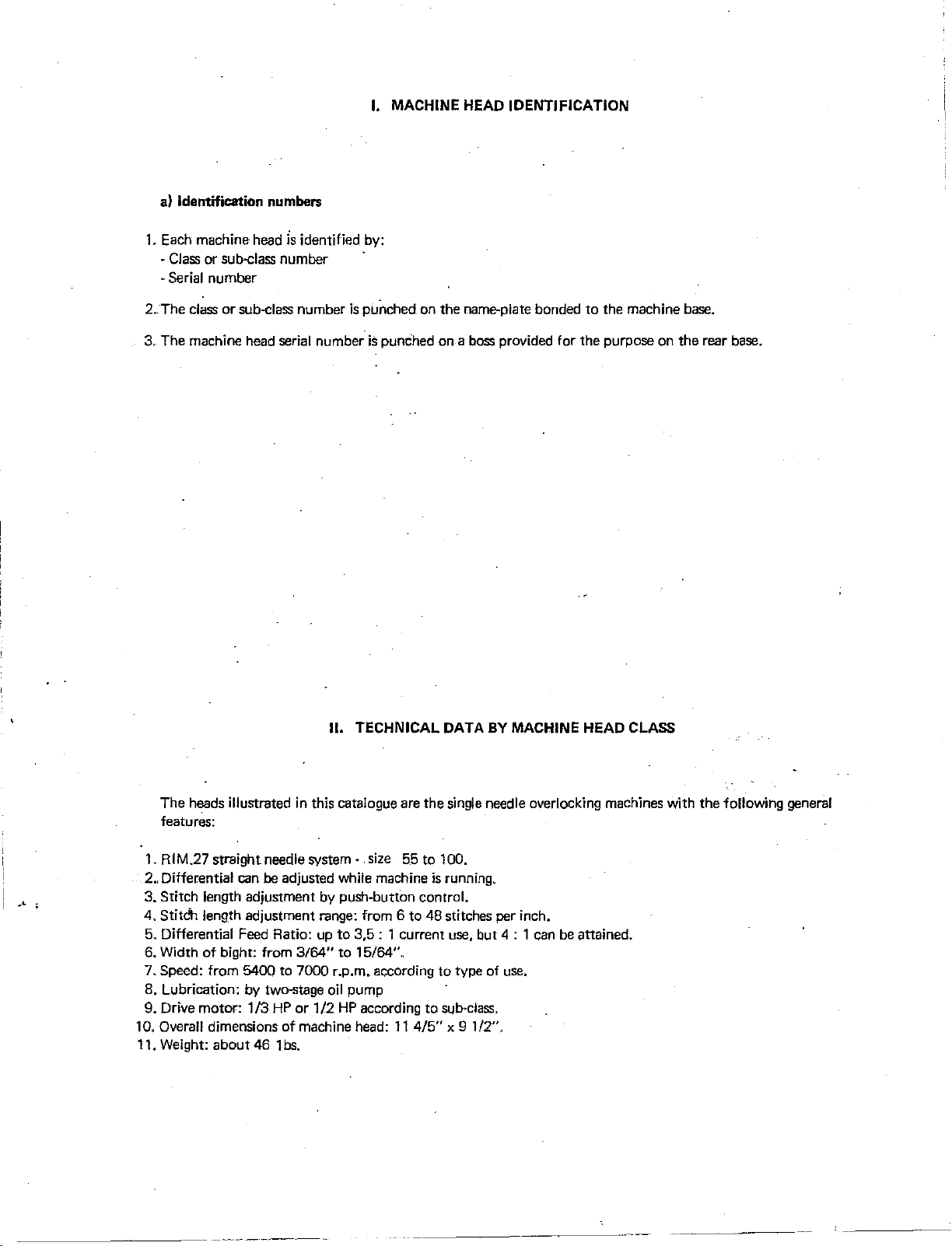
I. MACHINE HEAD IDENTIFICATION
numbers
1. Each machine head
· Class or sub-class number
·Serial number
2. The class
3.
The machine head serial number
or
sub-class number
is
identified by:
is
punched on
is
punched
the
name-plate bonded
on
a boss provided for the purpose
to
the machine base.
on
the
rear base.
II. TECHNICAL DATA
The
heads illustrated in this catalogue are
features:
1. RIM.27 straight needle
Differential can be adjusted while machine
2.,
3.
Stitch length adjustment by push·button control.
Stitdh length adjustment range: from 6
4.
5. Differential Feed Ratio: up
of
6. Width
7. Speed: from
8,
Lubrication: by two-stage
9. Drive motor:
10. Overall
11. Weight:
bight: from 3164"
5400
1/3
dimensions
about
46
system·
to
7000
HP
or
1/2
of
machine head:
1 bs.
size
55
to
to
3,5:
1 current use,
to
15/64".
r.p.m. according
oil
pump
HP
according to sub·class.
11
BY
MACHINE HEAD
the
single needle overlocking machines with
to 100.
is
running.
48 stitches per inch.
but
4 : 1 can be attained.
to
type of use.
4/5"
x 9 1/2".
CLASS
the
following general
Page 5
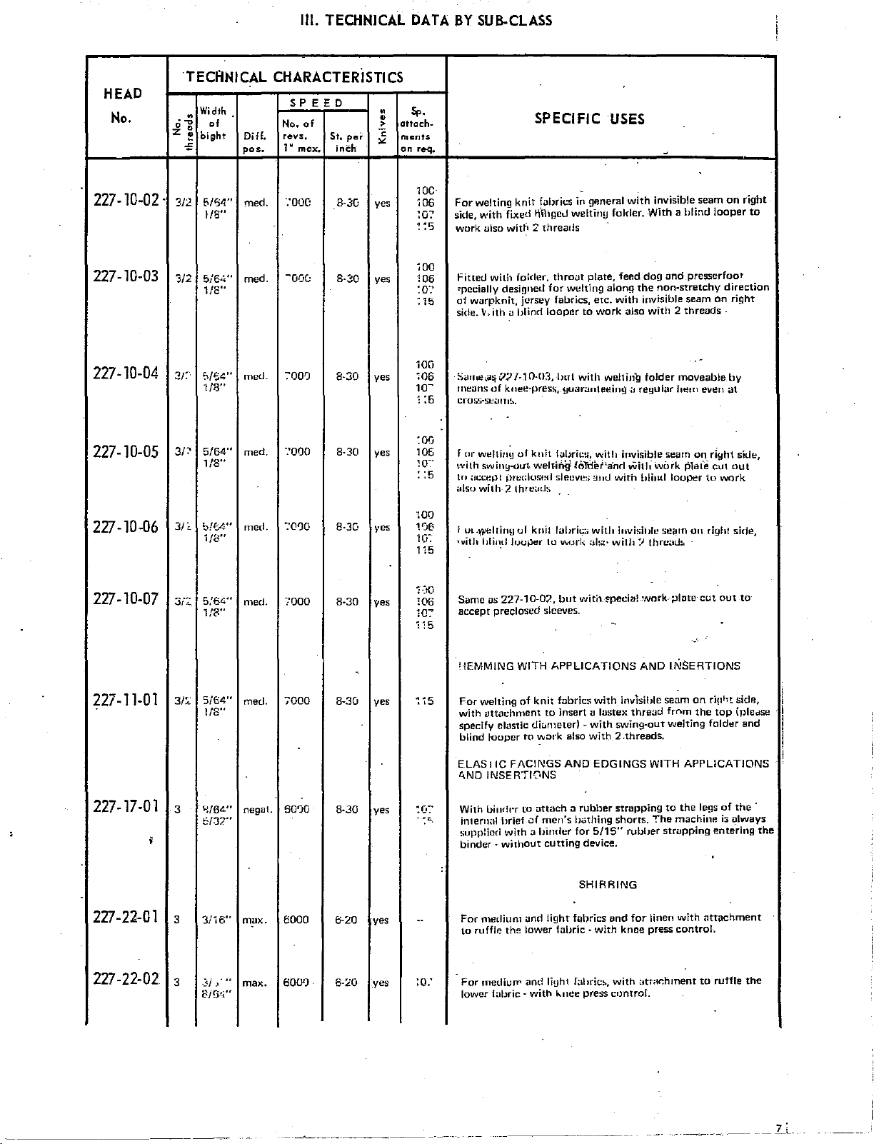
Ill.
TECHNICAL
DATA
BY
SUB-CLASS
HEAD
No.
227-10-02.
227-10-03
227-10-04
227-10-05
TECANICAL
Width
"
·~
of No.
0 0
z
~
bight
..,
5/S4''
3/2
1/8"
3/2
5i6•i"
1/8"
3/:
f>/f.4"
1/8"
5/64"
3r:'
1/8"
CHARACTERiSTICS
SPEED
of
Diff.
pos.
med.
med.
mec.L
med.
revs.
1 N
·:ooc
~00(;
700')
·:ooo
max,
St,
inCh-
B·3u ye:;
8<'":!0
8·30
8-30
pel'
"
•
>
·;;
"
yes
yes
yes
Sp.
attach-
ments
on
iOO
106
10-
':5
I
:oo
105
w~·
re-q,
100
For
i06
side,
~o:
~ ~
5
work
jQQ
fitted
'!06
~pm:ially
:o:·
of
:
15
side.
SarJ1e-.a~
means
crm;S·S!:!<IIIl!>.
fur
with
:
:5
to
also with- 2 threuLI:,
SPECIFIC
welting
knit
with
fixed li'illgcll weltin!J folder. With a
ulso
with 2 threads
with
folder.
desinned
warpknit,
wei tiny
;n;cept
jersey
lJ,
ith
i.l
blind
V/
/·1
0-03,
of
kne~·pres!;,
of
swiny·out
knit
welt-irllj f0ldet'a'nrl With wOrk Plale
~>ret:lusml
.
fabrics in gP.neral
throut
plate,
for
Wt!lting
fabrics,
looper
etc.
to
work
lml
with
yuaranteeing
l<a!Jril::;1 Vl.:ith
!>leeve:;
auLl
USES
with
feed
along
with
also
welting
01
iT•visible
with
~
invisible seam
blind
do~l
<Jnd.presserfoot
the
non-stretchy
invisible
reyular
blind
seam
with 2 threads
folder
moveable.
hem
seam
looper
looper
on
.
e\!en
011_
riyht sitlt!,
cut
to
on
right
to
direction
right
-
by
at
out
work
227-10-06
227-10-07
227-11-01
227-17-01
I
227-22-01
3/~
b!EA"
5.'64"
3/:~
1/8"
5i64"
3/~~
~/64"
3
f::/J2"
3
3/16''
1/8"
1/8"
med.
med.
med.
negat.
max.
''C%
7000
7000
6090
6000
8-3G
\•es
8-30
yes
.
8-30 yes
yes
8·30
yes
6-20
·:oo
10B
10:
115
i·)O
!06
10:'
ii5
~'iS
:o:-
...
..
f Ul-(lltdfiny
•vith
hli•~tl
Same
as
227-10-02,
accept
preclosed
'lEMMING
For
welting
with
uttm:hment
specify
clustic diLJmeterl
blind
looper
ELASIIC
t...,NQ
INSERTIONS
With Uind1·r
internal
brief
supplied
binder·
without
For
medium
to
ruffle
ul
knit
Juoper
FACINGS
with a hinder
the
fabril::; wit!• h•visil•fe
to
Vllf.)l'k
but
sleeves.
WITH
APPLICATIONS
of
knit
fnbrics
to
insert
to
work
to
uttach ~ rubber
of
men's
cutting
and
light
lower
fabric·
:.~Is:·
with.
~pecia!
with
u lastex
-with
also
with 2 .threads.
AND
EDGINGS
hothing
for
5/15"
device.
SHIRRING
fubrics
with
se4:1m
on
with/
threaU~
work--;:JI~te-cut
right
..
"
;,NO
INSERTIONS
invisible
swing-out
strapping
shorts.
and
knee
thread
WITH
rubber
for
linen
press
seam
on
frnm
welting
APPLICATIONS
to
the
The
machine
stwpping
with
control.
ri!1ht sidP.,
the
folder
legs
ilttachment
side,
out
to
top
(pledse
and
of
the
i:;
always
entering
the
·
.5/
J
227-22-02
3
...
Bi5-'i"
max.
6000
6-:iO
yes :o:
For
lower
mediull'
f;,1bric-
and
with
li!Jh1_
lo.nee
fabric!>,
press
with
<~tWr.hment
control.
.
to
ruffle
the
_______
___
Lc
Page 6
Ill.
TECHNICAL
DATA
BY
SUB-CLASS
HEAD
No.
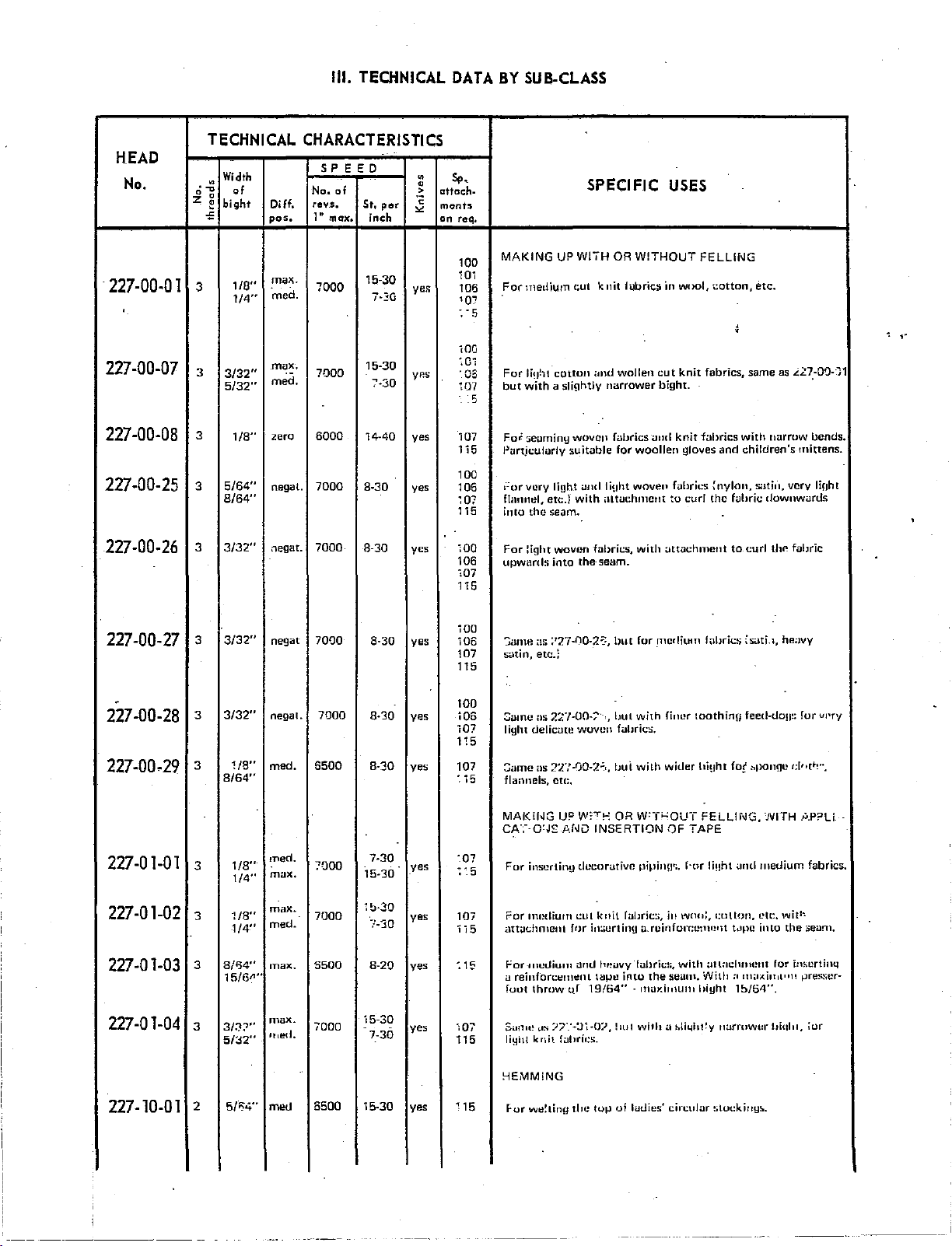
227-00-01
227-00-07
227-00-08
227-00-25
227-00-26
TECHNICAL
Width
.
·~
of
0 0
:z;
~
bight
~
1/S''
3
1/4
..
3
3/32
..
5/32
..
3
1/8
..
5/64
8/64
3/32
..
..
..
3
3
CHARACTERISTICS
SP
EED
No.
of
revs.
Oiff.
pos.
max.
"med.
max.
med.
zero
negat.
negat.
1" max,
7000 ye;;
7000
6000
7000
7000
St,
inch
15-30
7-~G
15-30
:'·30
14-40
8-30
8-30
per
Sp
•
•
>
attach-
c
monts
"'
on req.
100
101
106
1Q7
:.
iOG
:01
yP.s
·cs
107
. 5
yes
107
1 i 5 Purt.iculorly
100
yes
106
107
115
;oo
yes
I
106
"t07
115
•
MAKING
For
medium cut
5
For
li!Jhl
but
with a slightly
Foi
:;eominy
1::ur Vl.!ry li!)ht
flmmtll,
into the seam.
For
light
upwards into the seam.
UP
cotton
suitable
etc.}
woven
SPECIFIC
WIIH
OR
knit
;md
wollen
narrower
woven
fubrics uml
for
and
liuht
with
illti.Jt:hmcnt
fol>rics,
USES
WITHOUT
fubric:i in wool, ;;otton, etc.
woollen
wovefl
with
FELLING
I
cut
knit
fabrics,
bight.
knit
fabrics
gloves
fabrics~
to
curl
<.~ttuchment
same
with
and
children's
nylon,
satin,
the
f<.~hric
to
curl
as
..!2:~-Q')-]1
nurrow
bends.
mittens.
very
downwurds
li!Jht
thP fabric
,,
227-00-27
-
227-00-28
227-00.29
227-01-01
227-01-02
227-01-03
227-01-04
3
3
3
3
3
3
3
3/32
..
3/32
..
1/8"
8/64
..
1/8
..
1/4
..
1/8"
1/4
..
8/134"
15/611"
3/3'}"
51o2'"
neg
at
7000
negat. 7000
med.
6500
med.
7000
ml..IX.
max.
7000
med.-
max.
5500
max.
7000
lh!!d.
8-30
yes
8-30
yes
8-30 yes
7-30 '.07
7-30
8-20
7-30
yes
yes
yes
yes
15-30
~0-30
15-30
-
iOO
':iame
106
107 satin, etc.;
115
100
i06
107
115
107
. 15
:
'5
107
ii5
:1!3
107
115
il:i ;'27-{)0-2.:::,
Same
ns
light
delicum
:::ame as 2:t.'·'i0-7.,;,, tJut
flannels,
1\tlAI<ii>JG
CA::·-o:J£
For
inserting
For
nmdiurn
att<Jc.;hment
ror
-mullium
a reinfon:to"lllto"nt
fout
throw-
Si.l!llt!
,..:;
liyhl
knit_ fLJhril:s.
!-tEMMlNG
hut
for
2:.:"1-00-;'·--,
cu:.
UP
_.c,_f.JiJ
o_r
/7".'-:11-0/,
hut
woven
W:-T~
decorative
cut
ft>r
anll
19/64" -ITlUY.illlUlHIIiyht
whh
fi.JIJrics.
wilh
OR w:T;....:OUT FELLif>JG, '.IVITH
INSERTION
pipinw;.
knit
f<.~hric:;,
in:;crtinH
bt!i.JVY
Iabrie!;,
tape
into
!llll
with
_rncrlilHH
u.rcinfon:cnw•lt
the
h11>rics
firmr
tooth
wkler
hi~Jht
QF
TAPE
f·or
li!lht
in weHr:,
with
;lltadum!nt
seum.
With
:.1
~li4ht!y
isati.1,
inn
feed-UO!I~:
fo!' :.pongc
and
medium
t:ulton,
L'll:.
t.tpc
into
for
a
m;MilhL••n
lb/64".
nurwwtlr
lliqlll,
heilvy
fur
d"t•!
.U.P?U
with
the
seam.
in!.tlrtinq
tJre!:.'ier-
ior
vr•ry
..
,
fabrics.
5/13"4"
227-10-01
-------
2
m<!tl
6500
15-30
yes
115
F-or
we~ting
tlu!
tup
ol
h.Jt.lies'
cin;u]ur
!;tockiny!..
Page 7
Ill.
TECHNICAL
DATA
BY
SUB-CLASS
HEAD
No.
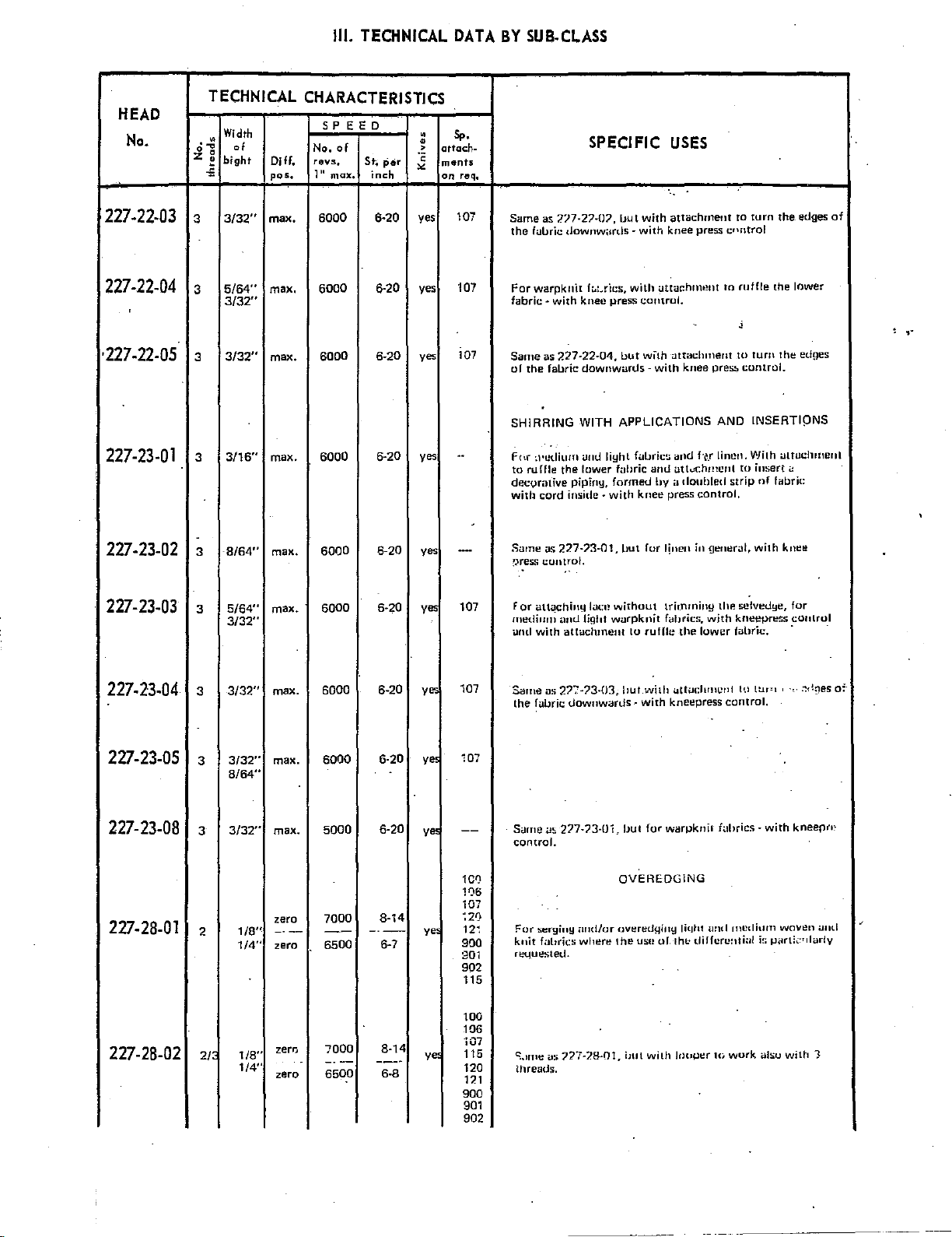
227-22-03
227-22-04
·227-22-05
227-23-01
227-23-02
TECHNICAL
Width
-~
of
0 0
z.
bight
.£
3/32"
3
5/64''
3
3/32"
3/32"
3
3/16"
3
8/64"
3
CHARACTERISTICS
S P E
ED
No.
of
revs
Dill.
pos.
max.
max.
max.
max.
max.
•
1" max.
6000
6000
6000
6000
6000
St.
inch
6·20
•
•
>
·c
per
"'
yes 107
yes
6·20
6-20 yes
yes
6·20
6-20 yes
s,.
attach-
ment.s
on
req.
107
107
..
-
.
SPECIFIC
Same
as ?.'77-27-07, Uut
the
fui.Jric
downw;1rds-
For
warpknit fuLdcs, with utmc:hment to ruffle the tower
fabric-
with
knee
press
with
with
knee
comrul.
USES
attachment
press
ro
turn
cnntrol
'
Same
as
2:?.7-22-04,
of
the
fabric
SHiRRING
fc,r
:l•cdium
to
ruffle
decvrative
with
Sarne
~res.<>
the
cord
as
227-?3-01,
control.
pipiny,
inside-
but
downwards-
WITH
APPLICATIONS
unt.l
lighl
lower
fuhric
formet.l
with
but
wllh
attachment
with
knee
preS!>
AND
fubric~
and
f·~.r
and
hy a doubled
knee
press
for linen in f)eneral,
linen.
att...r.hnnmt
control.
tu
tum
control.
INSERTI!)NS
1/'Jith Llttuchrl!erll
to
insert<:
strip
nf
with
the
the
fabric
kne~
edges
edges
of
,.
227-23-03
I
227-23-04
227-23-05
227-23-08
227-28-01
227-28-02
for
att~chinylacn
mediurn
and
Same
the
with
as
fa!Jric
antllight
i.ittadunent
27>73-03,
Y"'
ye
107
i07
107
5/64"
3/32"
3/32"
3/32"
max.
max.
max.
3
3
3
6000
6000
6000
6-20 yes
6-20
6·20
without
warpknit
to
ruHie
!Jut
UownwartJs~
with
with
trir_nminy
fabrics,
kneepress
thP.
!it:!lvedye,
with
the
<.~ttm:lummt
kne~press
lower
fabric. · ·
to
control.
UJI'I
for
control
-,.
~,!ges
•
of
8/64"
Sgme
a!.
217-?3·01,
For
:.erginy ;u1d/ur nvered{.liny lilJhl uml
fultrks
----
6-20
8·14
6-7
Y"'
ye>
--
1CQ
11)6
i07
~21
12,
900
901
902
115
control.
knit
requestell.
max.
3/32"
3
zero
1/8"
1/4"
-·-
zero
2
5000
7000
--
6500
where
!Jut
for
warpknit
OVEREOGiNG
the
ust! of.thl<
f;:thrics
·with
kneeprF
medium
diffurc~,ti:1l
woven
i~
1-l<~rll<:•dar!y
uml
100
106
2/
1/8"
1/4"
zero
zero
7000
----
6500
8·14
---·
6·8
ye
"i07
115
120
121
900
901
C::.nm~
as
??7-7.8-01,
threads.
but
with
hluper W work
alsu
with
1
902
Page 8
Ill.
TECHNICAL
DATA
BY
SUB-CLASS
HEAD
No.
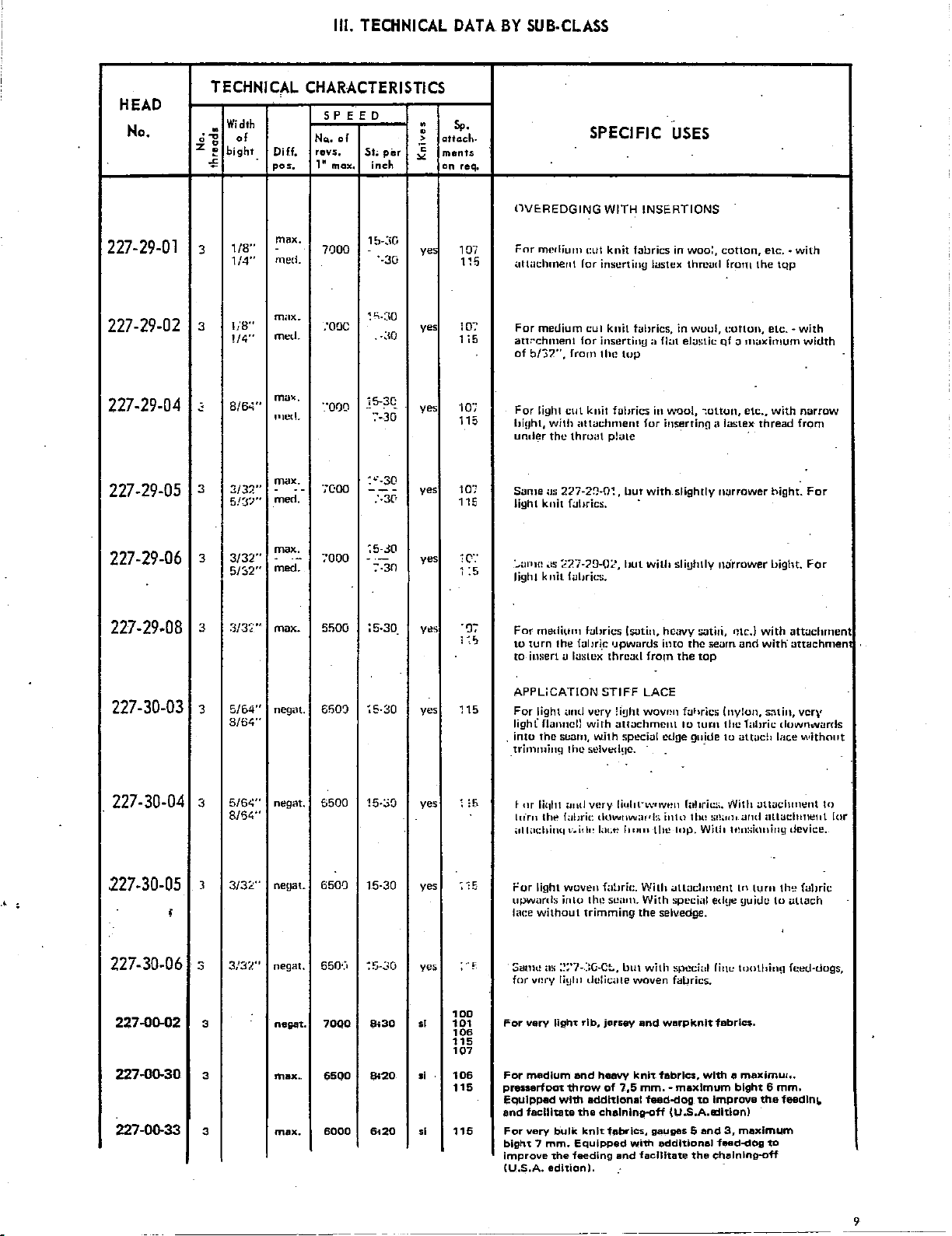
227-29-01
227-29-02
227-29-04
227-29-05
TECHNICAL
Width
.
·~
of
0 0
z
~
bight
.;;
1/8"
3
1/4"
1/8"
3
!/4"
8/6<i"
2
3
3/32"
5/3?"
CHARACTERISTICS
5 P E
ED
No..
of
fOV-5,
Oiff.
pos.
max.
-
mecl.
motx.
med.
max,
PlCtL
max.
merl.
1~
I
--
max,
7000
:ooc
·:ooo
-:coo
Sto
inch
1~<\G
"-30
~
C.-:JO
.<m
15-30
·:-30
:'"--30
---
:-3[•
per
Sp.
•
•
>
attach-
ments
"
"'
on
req,
ye
107
115
yes 10:'
1 i 5
yes
'107
i 15
yes
107
1 15
DVEoREDGING
For
nwllium
<ttl<Jclunent for
For
att;·chment
of
b/"37",
For
light
hi!Jht,
under
Same
light
t:ut
medium cut
for
frorn
cut
knit fabrics
with
itt
the
throat
iJ~;
227-2~-0~,
knit
f<~hrics.
SPECIFIC
WITH
INSERTIONS
knit
fabrics
inserting
inserting
llu~
tachment
lastcx
knit
h.tbrics, in wuul,
:1
top
for
p!<.~te
llut
with
·
USES
in
woo:,
cotton,
thrcml
rroTH
fiLII
in
waul, -:ottun,
ins~rtin!l
slightly
cotton,
el:.~~:tic
Qf o
a
laste_x
narrower
etc.·
the
tqp
etc.-
maximum
etc
..
with
thread
hight.
with
with
width
narrow
from
For
...
7000
5500
6!;0~
6500
6500
550·)
:5-JO
--
:'·30
:5-30
~6·30
15·:.>0
15-30
~5-.:m
yes
Yt!S
yes
yes
yes
yes
;c
1
:5
-~~
I;;
115
;
:5
: 15
:
"f,
:.,;,Hill!
.ts
lighl
For
to
to
APPLiCATION
For
ligh(
.
into
trhnrning
illlilchimt 1·.id•!
For
upwomb;
l<tce
Samt!
for
~27-79-o~·.
knit
fuiJries .
medium
turn
!he
insert
u
light
ami
flanncll
the
suarn, w.ith speciul
the
~
nr
liql11
ltlrn
omtl
th~
Iabrie
light
woven
inlo
without
m;
:~~·7-.::G-C::.,
v•!ry
liHIII
f-uhrics
f<11lri.c
Ia:,;
lex
very
with
selvt:tl!JC.
very
tluwnwaJ'!::.
lat;t~
th1~
trimming
tlciic<tte
!Jut
with
lsutin,
•Jpwan.ls
thrc<~tl
fro1n
STIFF
LACE
!iuht
wovr!n faf1rics
attachment
liullt·w•JVt!IJ
1111111
the
fahri1:.
Wilh
scam.
With
the
selv.edge.
but
wilb
woven
slightly
heavy
satili,
into
the
the
top
to
tum
ctlge
gu~de
ro:t!Jrit::;.
into
lht! st!;uJ•
top.
Wilh
all:Jchment
speci<tl
special
fai.Jrics.
narrower
ntc.l
iie<~rn
edye
rint:
with
and
with
(nylon,
satin,
the
Iabrie
to
<~ttucb
vVith
attaclunent
;md
illluchment
lt!n:>iuning
tn
turn
yuiUc
toothill!l
Uight.
For
attachment
attachmen
vcr\'
dowrhflfi!rds
lac.e
without
device.
the
fahric
to
utl:Jch
fceU-tlogs,
In
lt~r
227-29-06
227-29-08
227-30-03
227-30-04
227-30-05
;
3
3
3
3
3
5/~2"
~1/3·~·
5/6.4"
3/64"
5/6~"
8/64"'
3/3L"
..
mecl.
max.
negat.
negat.
negat.
-
.
max.
3/32'"
'
227-30.06
3/32"
3
negat.
227.00-02
227.00-30
227-0D-33
100
3
3
3
negat.
max.
max.
7000
6500
6000
!!i30
Bi20
6i20
10·1
ol
106
115
107
106
•I
116
ol
115
For
verv
For
medium
presaerfoot
l;::qulppad
end
facilitate
For
vary
bigh't 7
mm.
improve
(U.S.A.
editiOn).
llgh't
with
b'ulk knl't
the
rib,
and
throw
additional
the
Equipped
"feeding
jersey
and
heavy
knit
of
7,5
mm.-
fabrics,
with
and
feed-dog
gauges 5 and
facilitate
cholnlng-off
warpknlt
fabrics,
additional
fabriC$.
with
maximum
to
Improve
(U.S.A.a:Ution)
f..-d~og
the
c~alnlng-off
a
max.imu~o.
bight 6 mm.
the
3,
maximum
to
feadlnl.
9
Page 9
Ill.
TECHNICAL
DATA
BY
SUB-CLASS
HEAD
No.
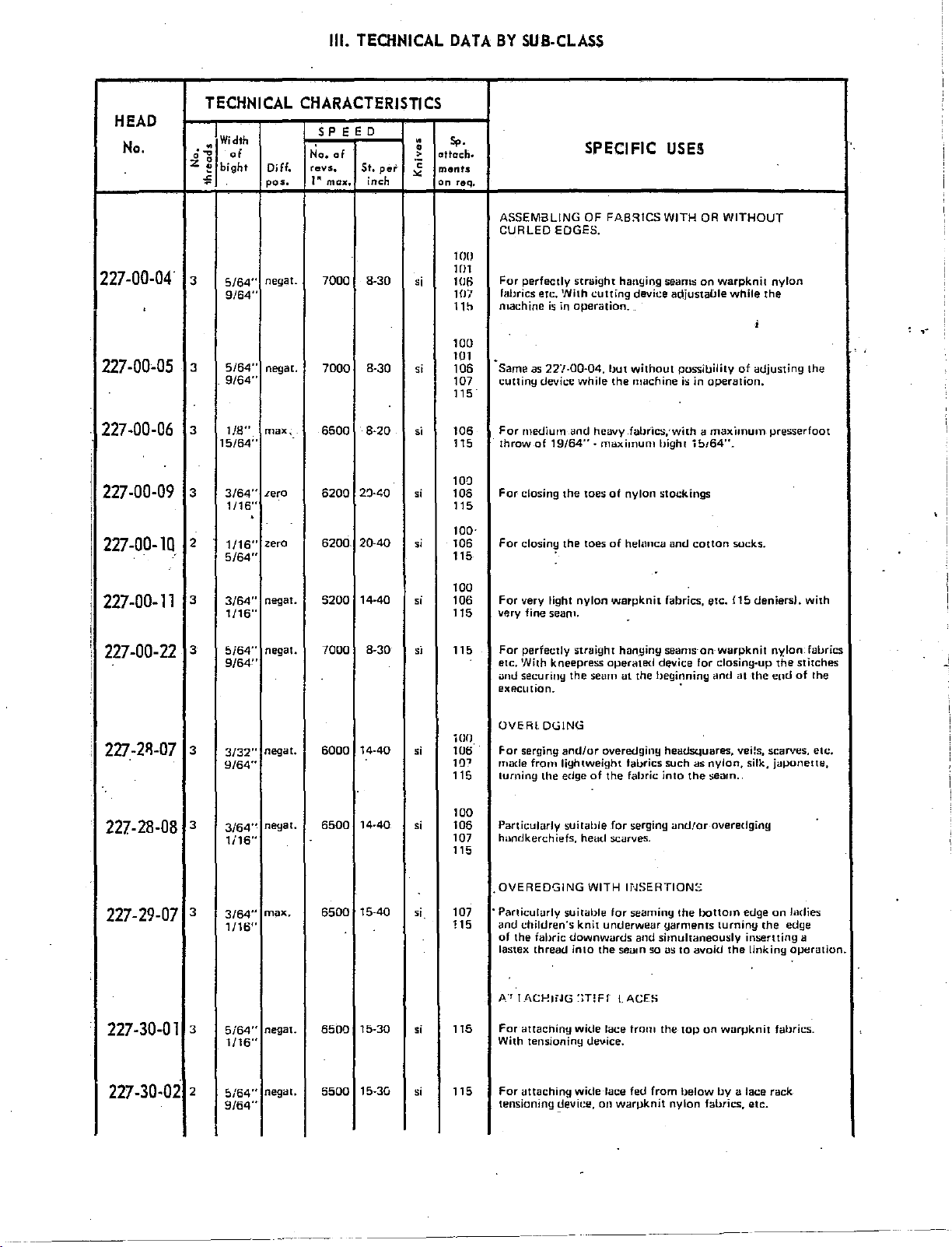
227-00-04
'
227-00-05
227-00-06
227-00-09
227-00-10
TECHNICAL
Width
•
·~
of
0 0
z
~
bight
"'
3
5/64"
9/64"
5/64"
3
9/64"
3
1/8"
15/64"
3
3/64"
1/16"
.
2
1/16"
5/64"
CHARACTERISTICS
S P E
ED
No.
of
revs.
Diff.
pos.
negat.
negaE.
max.
Lero
zero
1"
max.
7000
7000
6500
6200
6200
St.
inch
8-30
8-30
8-20
2'J-.t;.Q
20-40
pel'
•
•
>
.
.,
"'
si
,;
si
,;
,;
s,.
•
attach·
ments
on
req,
100
101
106
107
1 1 b
100
101
106
107
115.
106
115
100
106
115
100·
106
115
SPECIFIC
ASSEM3LING OF FABRICS
CUR
LEO EDGES.
For
perfectly
fabrics
machine
-
Same
cutting
For
medium
throw
For
closing
For
closing the toes
straight
etc.
With
is
in
as
22/-00-04,
device
ond heavy fabrics,cwith o
of
19/64"
the
hanging
cutting
operation.
but
while
the
·maximum
toes
of
of
device
without
mactiine
nylon
helomca and
USES
WITH
OR
seams
on
adjustable
possibility
is
in
bight
ibt64".
stockings
cotton
WITHOUT
warpknit
while
of
operation.
maximum
socks.
nylon
the
;
adjusting
presserfoot
,.
the
227-00-11
227-00-22
227-2ll-07
227-28-08
227-29-07
227-30-01
100
3/64"
1
/16''
5i64"
9/64"
3/32"
9/64"
3/64"
1i16"
3/64"
1/16''
5/64"
1
/16''
negat.
negat.
negat.
negat.
mj)X.
negat.
3
3
3
3
3
3
5200
7000
6000
6500
6500
6500
14-40
8-30
14-40
14-40
15-40
15-30
,;
106
115
si
115
iOO
si
106
HP
115 turning
100
s;
106
107
115
,;
107 · Particulurly
115
,;
115
For
very light
very fine seam.
For
perfectly
etc.
With
unU
execution.
OVERl
For
made
Particularly
handkerchiefs,
.
OVEREDGING
and
of
lastex
A."'
For
With tensioning
kneepress
securing
DGING
serging
from
the
children's
the
fabric
thread
IACI-!tiJG
<Htachiny
and/or
lightweight fabrics such
edge
nylon
warpknit
straight
operated
the
seam
overedginy
of
the
suitable
for serging
head
scarves.
WITH
suitable
for seaming
knit
underwear
downwurds
into
the
:>T!H
wide
lace
(,!e..,.ice.
f<d>rics,
hanging
seams-on-warpknit
device for closing-up
at
the
begi~ning
headsquares,
fabric
into
;md!or
INSERTIONS
the
garments
and
simultaneously
seam
so as
to
LACE~
from
the
top
etc.
and
as
nylon,
the
seam.
overedging
bottom
avoid
on
£15
deniers).
at
the
veHs, scarves,
silk,
edge
turning
insertting
the
linking
wurpknit
nylon
the
ea1d
juponette,
on
ladies
the
edge
operation.
fabrics.
with
fabrics
stitches
of
the
etc.
a
..!
227-30-02
5/64"
9/64"
negat.
2
5500
15-30
115
si
For
<Jttaching
tensioning
~evit!e,
wide
lace fed
on
wan.Jknit
from
below
nylon
by
a lace rack
fabrics.
etc.
Page 10
INSTRUCTIONS
_
INSTALLATION
_ USE
_
MAINTENANCE
:FOR
AND
TIMING
--~-----'---~
--
-
-~-----~---~
------····-
-u
i
Page 11
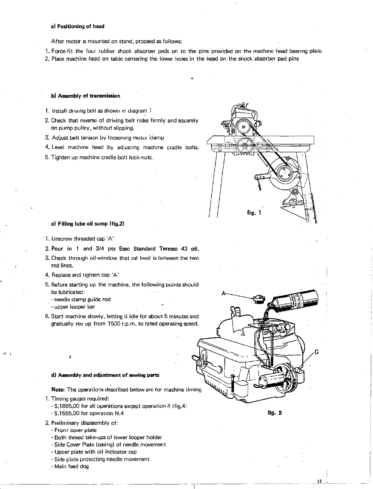
a)
Positioning of head
1s
After motor
1.
Force-fit the four rubber shock absorber pads on to the pins provided on the mach1ne head bearmg plate
2. Place machine head on table centering the lower holes
b)
As$embly of transmission
1.
Install dnvmg belt as shown
mounted on stand, proceed as follows:
1c
d1agram
1
in
the head on the shock absorber pad pins
2. Check that reverse of driving belt rides firmly and squarely
on pump pulley, without slipping:
3:
Adjust belt
4,
Level
tenSIOn
machme
by loosenmg motul clamp
head
by
adjusting
machine
cradle
bolts.
5. Tighten up machine cradle bolt lock-nuts.
c)
Filling lube oil sump (fig.2)
1. Unscrew threaded cap 'A'
2. Pour
3. Check through oil-window that
in
1 and
3/4
pts
Esso
Standard Teressa
011
lev"l
red lines.
4. Replace and tighten cap 'A'
5. Before starting up the machine, the
following points should
be lubricated:
· needle clamp guide rod
· upper looper bar
6.
Start
machine slowly, letting it idle for about 5 minutes and
gradually
rev
up from 1500 r.p.m.
to
rated operating speed.
'
d)
As$embly and adjustment
Note: The operations described below
1. Timing gauges required:
- S.1665.00 for
all
operations
- S.1555.00 for operat10n N.4
2. Preliminary disassembly of:
- Front cover plate
· Both thread take-ups of lower looper holder
·Side
Cover Plate
- Upoer plate with oil indicator
-Side
plate protecting needle movement
-
Main
feed dog
(casing}
of
sewing parts
are
ex~ept
operation 4 (
of needle movement
cap
43
oil.
is
between the two
for machine timing.
fig.41
fig. 2
r-----~-
-------
- -
_____li_
_
_;~~~
Page 12
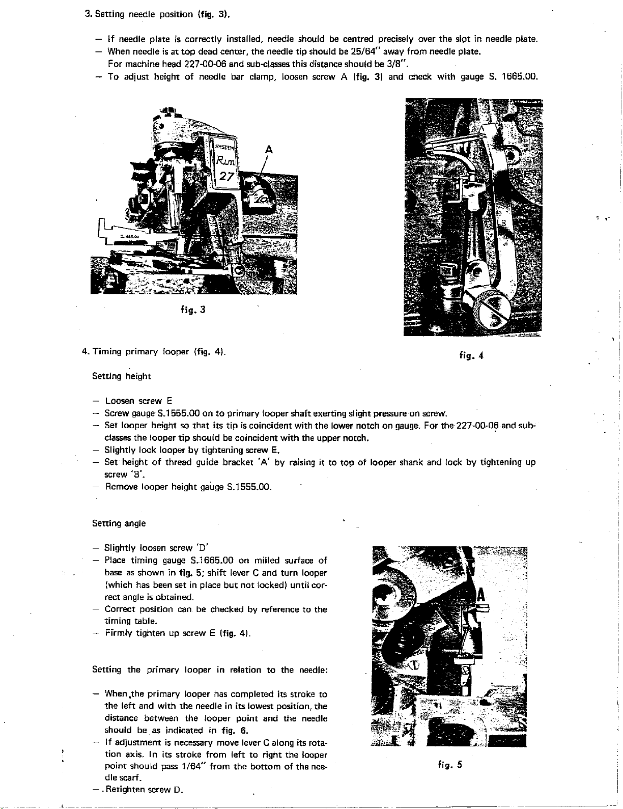
3. Setting needle position (fig. 3).
If
needle plate
When
needle
For machine head
To adjust height
is
correctly installed, needle should be centred precisely over
is
at
top
dead center, the needle tip should
227.00·06 and sub-classes this distance should be 3/8".
of
needle bar clamp, loosen screw A (fig. 3) and check with gauge S. 1665.00.
be
25/64"
the
slot
in
away from needle plate.
needle plate.
,-
fig.
3
4.
Timing primary looper (fig. 4).
Setting height
Loosen
Screw gauge S.1555.00
Set looper height so
classes
screw E
the
looper
on
to
primary looper shaft exerting slight pressure on screw.
that
its
tip
is
coincident with
tip
should be coincident with the upper notch.
Slightly lock looper by tightening screw
Set height
screw
'8'.
of
thread guide bracket 'A' by raising it
Remove looper height gauge S.1555.00.
Setting
angle
Slightly
loosen screw
'D'
Place timing gauge S.1665.00 on milled surface
base
as
shown
(which
rect angle
has
Correct position
timing table.
in
fig. 5; shift lever C and turn looper
been set in place
is
obtained.
can
be
but
not
locked) until cor-
checked by reference to the
Firmly tighten up screw E (fig. 4).
E.
the
lower notch on gauge. For
to
top
of
looper shank and lock by tightening up
of
4
fig.
the
227·00.06 and sub-
Setting the primary looper
When .the primary looper
the left and with the needle
in
relation to the
has
completed its stroke
in
its lowest position, the
needle:
to
distance between the looper point and the needle
should be
If
adjustment
tion axis. In its stroke from left to right the looper
point should
as
indicated
is
necessary move lever C along its rota-
pass 1 /64"
in
fig.
6.
from the bottom
of
the
nee-
dle scarf .
. Retighten screw
D.
fig. 5
Page 13
D.
1111!111!;;1
.:>~L;UfLUdiY
LUUf.J~I
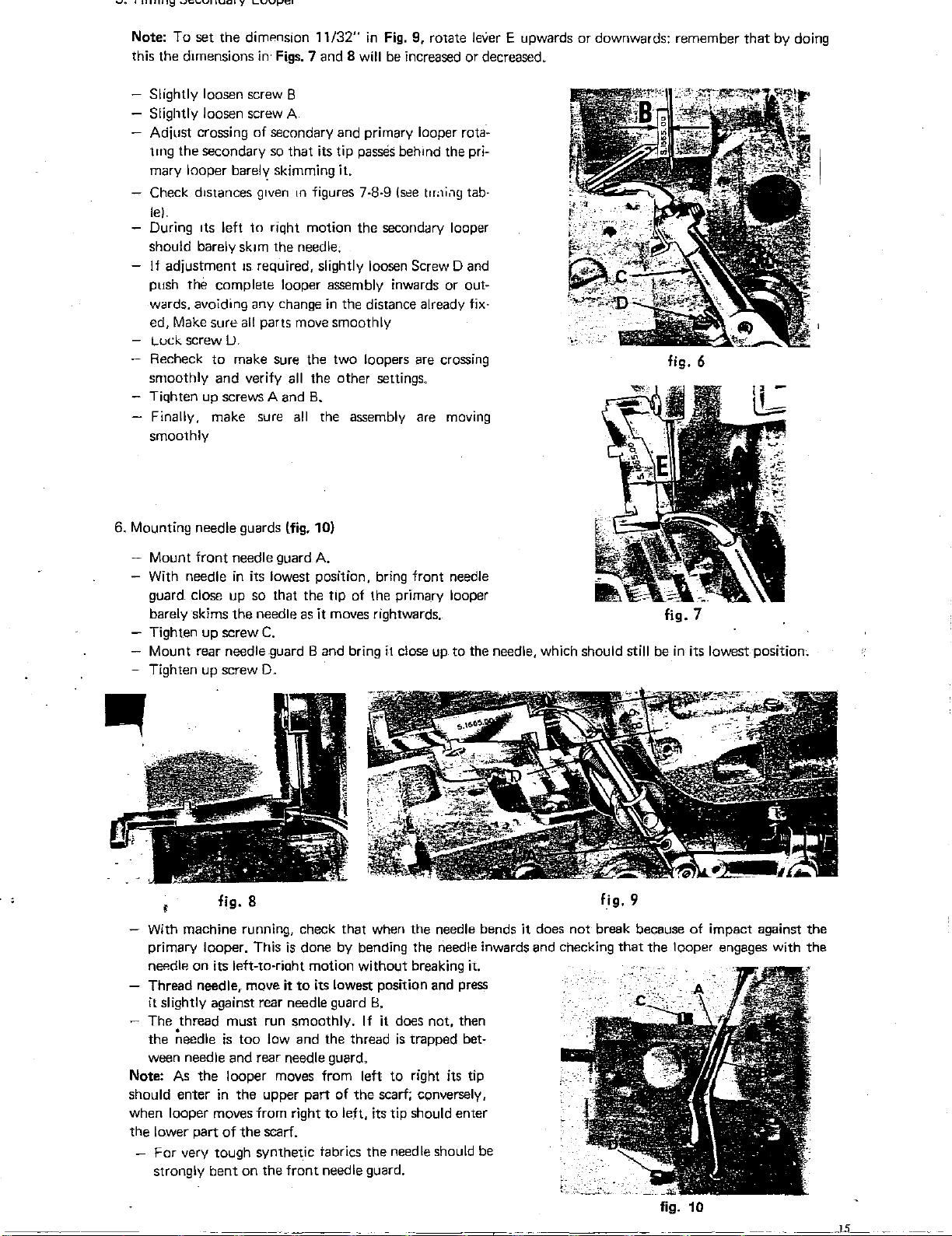
Note: To set
this the dimensions
the
dimenSion
in·
Figs. 7 and 8
Slightly loosen screw 8
Slightly loosen screw A
Adjust crossing
the
tlllg
secondary so that its tip passes behmd the pri-
of
secondary and primary looper rota-
mary looper barely skimming it.
Check distances gtven
tn
le).
During
should barely
If
push
1ts
left
adjustment
the
complete looper assembly inwards or out-
to
riqht motion the secondary looper
sk1m
the needle.
IS
required, slightly loosen Screw 0 and
wards. avoiding any change
ed, Make
Luck screw
Recheck
smoothly and verify
sure
all
parts move smoothly
LJ.
to
make sure the two loopers are crossing
all
Tiqhten up screws A and
- Finally, make sure
all
smoothly
11/32"
figures 7-8-9
in
Fig. 9, rotate
will
be increased or decreased.
(see
in
the distance already
tno1i.1g
the other settings.
B.
the assembly are moving
lever
tab-
fix-
E upwards
or
downwards: remember
fig. 6
that
by doing
6. Mounting needle guards lfig.
- Mount front needle guard
With needle
in
its lowest position, bring front needle
10)
A.
guard close up so that the tip of the primary looper
barely skims the needle as it moves rightwards. fig. 7
- Tighten up screw
Mount rear needle guard 8 and bring
Tighten up screw 0
-
With machine running, check that when
primary looper. This
neP.dle
on its left-to-rioht motion without breaking it.
Thread needier move it
it slightly against rear needle guard
The thread must run smoothly.
~eedle
the
C.
..
fig. 8
is
done by bending the needle inwards and checking
to
its lowest position and press
is
too low and the thread
it
close up
the
needle bends it does not break because
B.
If
it does not, then
is
trapped bet-
to
the needle, which should still be
lig.9
that
ween needle and rear needle guard.
As
the
Note:
should enter
looper moves from left
in
the upper part of
when looper moves from right
part
of
the
the lower
scarf.
For very tough synthetic tabrics
strongly
bent
on the front needle guard.
to
left, its tip should enter
to
right its tip
the
scarf; conversely,
the
needle should be
in
its lowest positionc
of
impact against
the
looper engages with
the
the
fig. 10
___
,_1.5_
Page 14
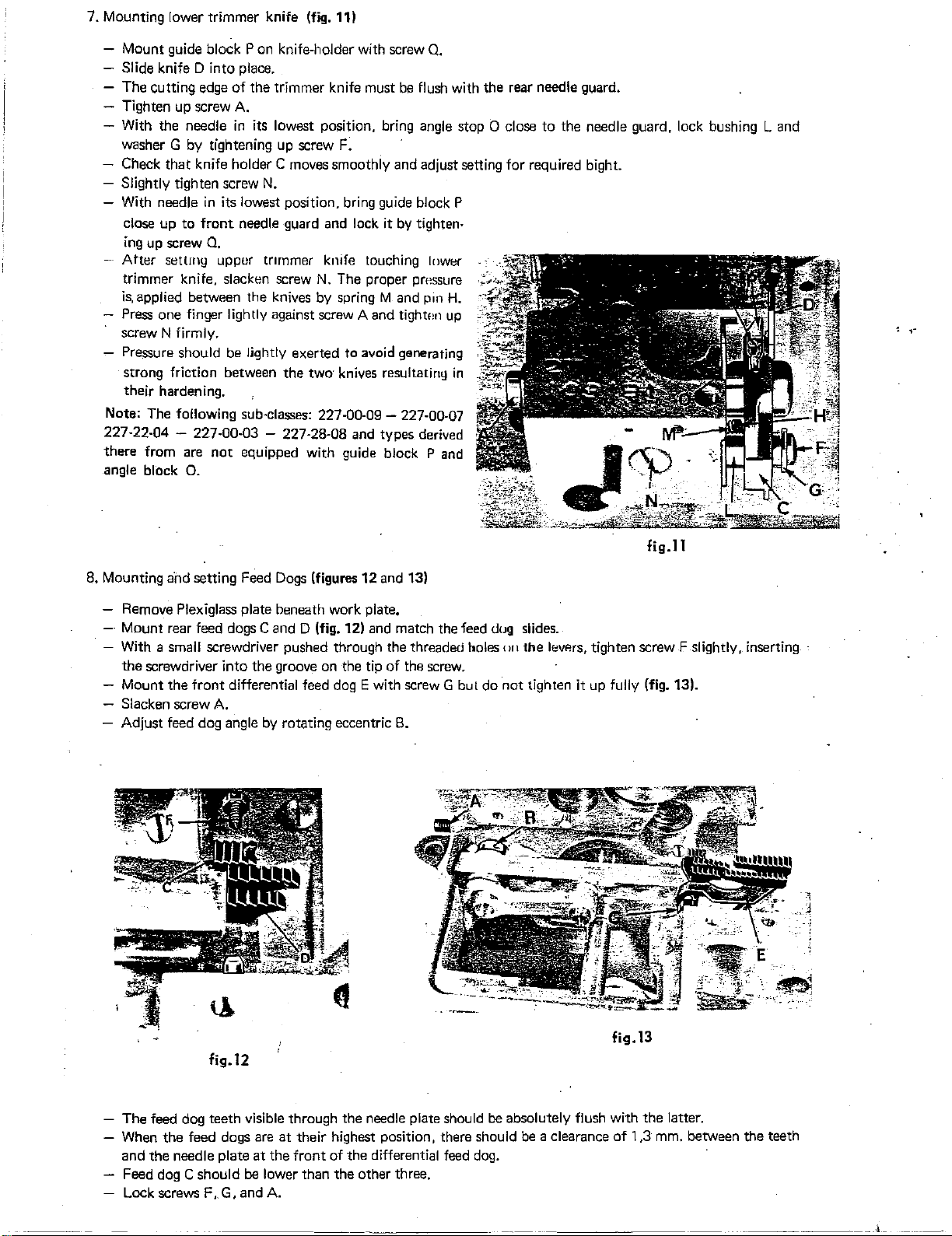
7. Mounting lower trimmer knife (fig. 11)
- Mount guide block P on knife-holder with screw
- Slide knife D into place.
- The cutting edge
- Tighten up screw
- With the needle
of
the trimmer knife must
be
A.
in
its lowest position. bring angle stop 0 close to the needle guard, lock bushing L and
washer G by tightening up screw F.
- Check
- Slightly tighten screw
-
that
knife holder C moves smoothly and adjust setting for required bight.
N.
With needle
close up to
ing
up screw
Atter
trimmer knife. slacken screw
is,
applied between the knives
Press
in
its lowest position. bring guide block P
front
needle guard and lock it
0.
settmy upper tnrnmer knife touching lower
N.
The proper pressure
by
spring M and
one
finger lightly against screw A and
by
tightt~n
screw N firmly.
Pressure
strong friction between the two· knives resultatiny
should
be
lightly exerted to avoid generating
their hardening.
Note: The following sub-classes:
227·22-04 - 227-00-03 - 227·28·08
not
there from are
angle block
0.
equipped with guide block P and
227·00·09-
and types derived
227·00·07
0.
flush with the rear needle guard.
tighten·
pin H.
up
in
8. Mounting and setting Feed
Dogs
(figures
12
and 13)
- Remove Plexiglass plate beneath work plate.
- Mount rear feed dogs C and D (fig. 12) and match the feed
- With a small screwdriver pushed through the threaded
the
screwdriver into the groove on the tip of the screw.
- Mount the front differential feed
- Slacken screw
- Adjust feed dog angle
A.
by
rotating eccentric
dogE
with screw G but do not tighten it up fully (fig. 13).
B.
dug
boles'"'
slides.
the
levP.rs,
lig.ll
tighten screw F slightly, inserting
fig.l2
- The feed dog teeth visible through the needle plate should be absolutely flush with the latter.
- When
the
feed dogs are
and the needle plate
at
their highest position, there should
at
the front of the differential feed
dog.
be
a clearance of 1,3
Feed dog C should be lower than the other three.
- Lock screws F, G, and A.
lig.l3
mm.
between the teeth
--L
--------·
Page 15
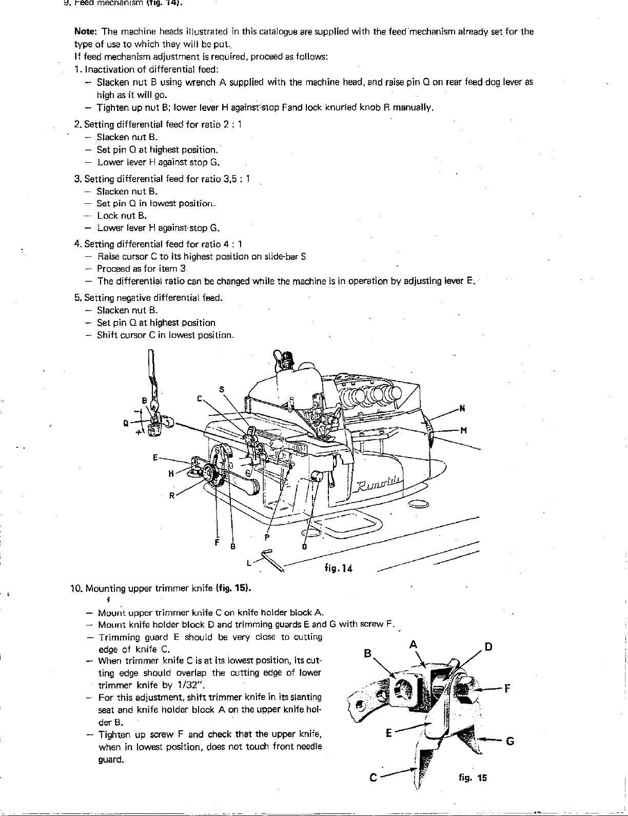
8.
1-eed
mechamsm \fig.
14).
Note: The machine heads illustrated
to
type of use
If
feed mechanism adjustment
Inactivation of differential feed:
1.
- Slacken
high as it
- Tighten up nut
which they will
nut
B using wrench A supplied with the machine head, and raise pin Q on rear feed dog lever as
will
go.
B;
lower lever H against-stop Fand
in
this catalogue are supplied with the feed·mechanism already
be
put
..
is
required, proceed
as
follows:
2. Setting differential feed for ratio 2 : 1
- Slacken nut
- Set pin Q
- Lower lever H against stop
B.
at
highest position.
G.
3. Setting differential feed for ratio 3,5 : 1
Slacken
-
-
Set
- Lock
- Lower lever H against stop
pin Q
nut
nut
B.
in
lowest position.
B.
G.
4. Setting differential feed for ratio 4 : 1
Raise
cursor
C to
its
highest-
- Proceed as for item 3
position
on
slide-barS
- The differential ratio can be changed while the machine
5. Setting negative differential feed.
Slacken nut
Set pin
Shift cursor C
B.
Qat
highest position
in
lowest position.
lock
knurled knob R manually.
is
in
operation by adjusting lever
E.
set
for the
Q
10. Mounting upper trimmer knife (fig. 15).
I
- Mount upper trimmer knife
-
Mount
- Trimming
edge of knife
When
knife holder block D and trimming
guard E should
C.
trimmer knife C
Con
knife holder block
be
very
close
is
at
its lowest position, its cut-
guards E and
to cutting
ting edge should overlap the cutting edge of lower
trimmer knife by 1
For this adjustment, shift trimmer knife
seat and knife holder block A
der
8.
/32".
in
on
the upper knife
its slanting
- Tighten up screw F and check that the upper knife,
in
when
lowest position, does not touch front needle
guard.
A.
G with screw
hol-
F.
A
D
G
Page 16
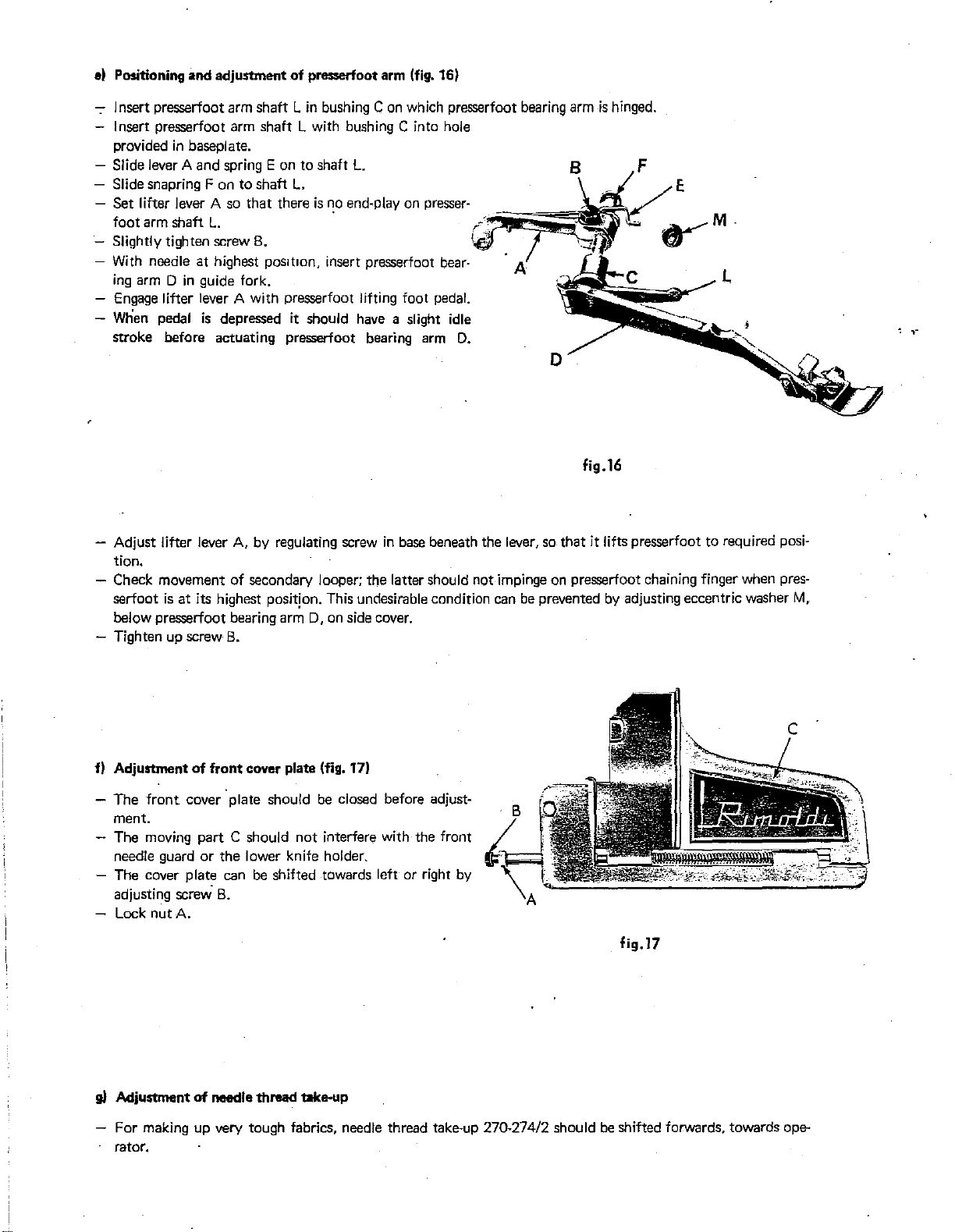
el Positioning and adjuotment
of
presserfoot
arm
(fig. 16)
- Insert presserfoot arm shaft
Lin
bushing
Con
which presserfoot bearing arm
Insert presserfoot arm shaft L with bushing C into hole
in
provided
- Slide lever A and spring E on to shaft
- Slide snapring F on to shaft
- Set lifter lever A so that there
foot arm shaft
- Slightly tighten screw
-
With
ing
arm 0
-
Engage
-
When
stroke before actuating presserfoot bearing
- Adjust lifter lever
tion.
baseplate.
L.
L.
is
no
end-play on presser-
L.
B.
needle at highest
in
guide fork.
pos1t1on,
insert presserfoot bear·
lifter lever A with presserfoot lifting foot pedal.
pedal
is
depressed it should
have
a slight idle
arm
A,
by regulating screw
in
base beneath the lever, so that it lifts presserfoot to required posi-
- Check movement of secondary looper; the latter should
serfoot
below presserfoot bearing arm
- Tighten up screw
is
at
its highest positjon. This undesirable condition can
0,
on side cover.
B.
is
hinged.
B F
E
-~~r;;;;;;?
:_
D,
fig.16
not
impinge on presserfoot chaining finger when pres-
be
prevented
by
adjusting eccentric washer
M,
f)
Adjustment
- The
ment.
- The moving part C should
of
front cover plate (fig. 17)
front
cover plate should
be
closed before adjust-
not
interfere with the front
needle guard or the lower knife holder.
- The cover plate can
adjusting screw.
B.
be
shifted towards left or right
by
- Lock nut A.
g)
Adjustment
of
needle thread take-up
For making up very tough fabrics, needle thread take-up 270-274/2 should
rator.
fig.l7
be
shifted forwards, towards ope-
Page 17
h)
Disassembly
ELECTRIC
and
replacement of
LUBRICATION
pressure
switch
CONTROL
DEVICE
(PRESSURE
SWITCH)
- Take down oil cup from baseplate and drain
Remove screw
by
which pressure switch bracket
- Slacken the two screws on the electric wire terminal
-
Slip
plastic tube connecting pressure switch
- Remove bracket and fix it
to
new pressure switch.
out
oil.
is
mounted on
oil
cup.
lugs.
to
rubber connection off the pressure switch.
Screw down electric wire lugs, slip plastic tube into pressure switch and mount switch on
screws
previously
Re-install
Replacement
Proceed
oil
of
as
Remove rubber tube, remove lamp (bayonet
Re-install rubber tube, replace pressure switch
Re-install
Electrical
oil
connection
removed.
cup and
pressure
fill
with
switch
oil
as
instructed on
lamp
page
11, par
c.
described under items l and 2 for replacement of pressure switch.
cap)
and replace with new lamo.
in
position and fasten firmly to
cup and
fill
of
pressure
with oil
switch
as
instructed on
on
Zefir
page
motors
11, par. c
..
oil
wrth screw
oil
cup using
the
-
Plug
cable
to
current socket and insert
Note:
If
with
no light socket
12
V.
connections, proceed
is
provided on the motor to be connected, but the voltage connection box
Mount a Mignon socket pitch 13
light terminal
Plug
cable
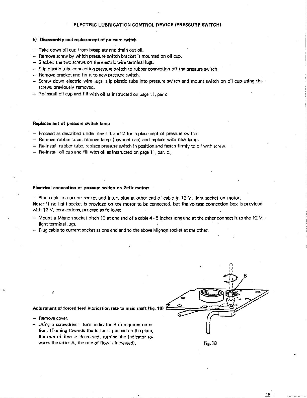
-
Remove
Using
a screwdriver, turn indicator B
lugs.
to
current socket
cover.
as
follows:
at
one end and
at
one end
plug
at other end of cable
of
a cable 4-5 inches long and
to
the above
ih
required direc-
tion. (Turning towards the letter C puched on the plate,
the
rate
of
flew
is
decreased,
wards the letter A, the rate
of
turning
flow
the indicator to-
is
increased).
Mign"!n
in
socket
12
V.
light socket on motor.
at
the other connect it
at
the other.
fig.lB
is
provided
to
the
B
12
V.
----~1~9
'
Page 18
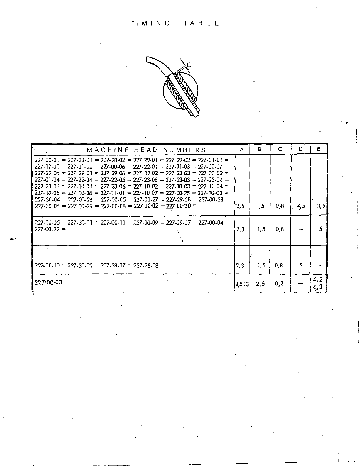
TIM
I N G T A 8 L E
MACHINE
227-00-01 = 227-28-01 = 227-28-02 = 227-29-01 = 227-29-02 = 227-01-01
227-17-01 = 227-01-02 = 227-00-06 = 227-22,01 = 227-01-03 = 227-00-07
227-29-04 =
227-01-04
227-23-03 = 227-10-01
227-10-05 = 227-10-06 = 227-11-01 = 227-10-07 = 227-00-25 = 227-30-03
227-30-04· = 227-00-26
227-30-06 = 227-00-29 = 227-00-08
227-00-05 = 227-30-01 = 227:00-11 = 227-00-09
227-00-22
227-00-10 = 227-30-02 = 227-28-07 = 227-28-08
227'00·33
227-29-01 = 227-29-06 = 227-22-02 = 227-22-03 = 227-23-02
= 227-22-04 = 227-22-05 =
= 227-23-06 = 227-10,02 =
= 227-30-05 =
= 2,3 1,5
HEAD
227-23-08 = 227-23-03
227-00-27 = 227-29-08 = 227-00-28
=
227-00-Q2
NUMBERS
= 227-23-04 =
227-10-03 = 227-10-04
=227-00-30 = . 2,5 1,5 0,8
= 227,29-07 = 227-00-04 =
'·
'·
..
= 2,3 1,5
.
-
-·
A B c
=
=
=
=
=
=
2,5f3
2,5
0,8
0,8
0,2
D
4,5
--
5
-
\
E
3,5
J4,2
\
4,3
I .
5
-
~~-
-~~~~--~~~~~~~~~~~~~~~·~-··-
. '
Page 19
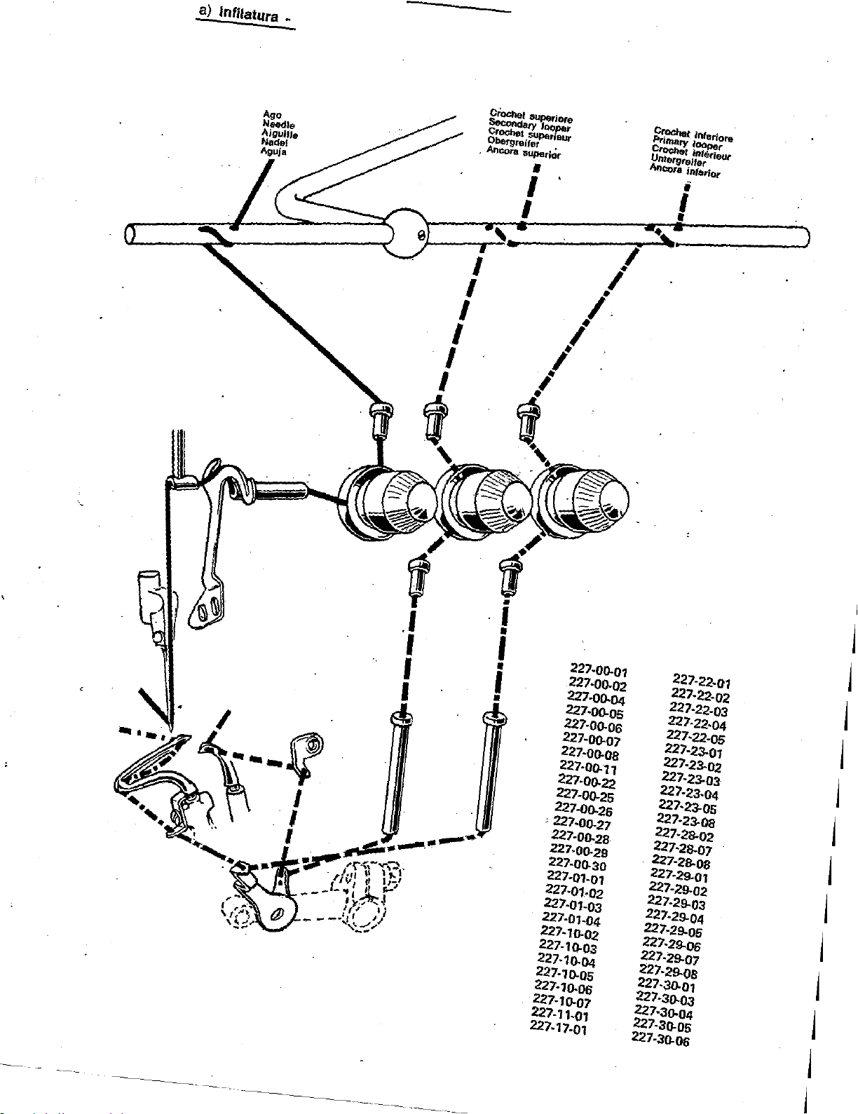
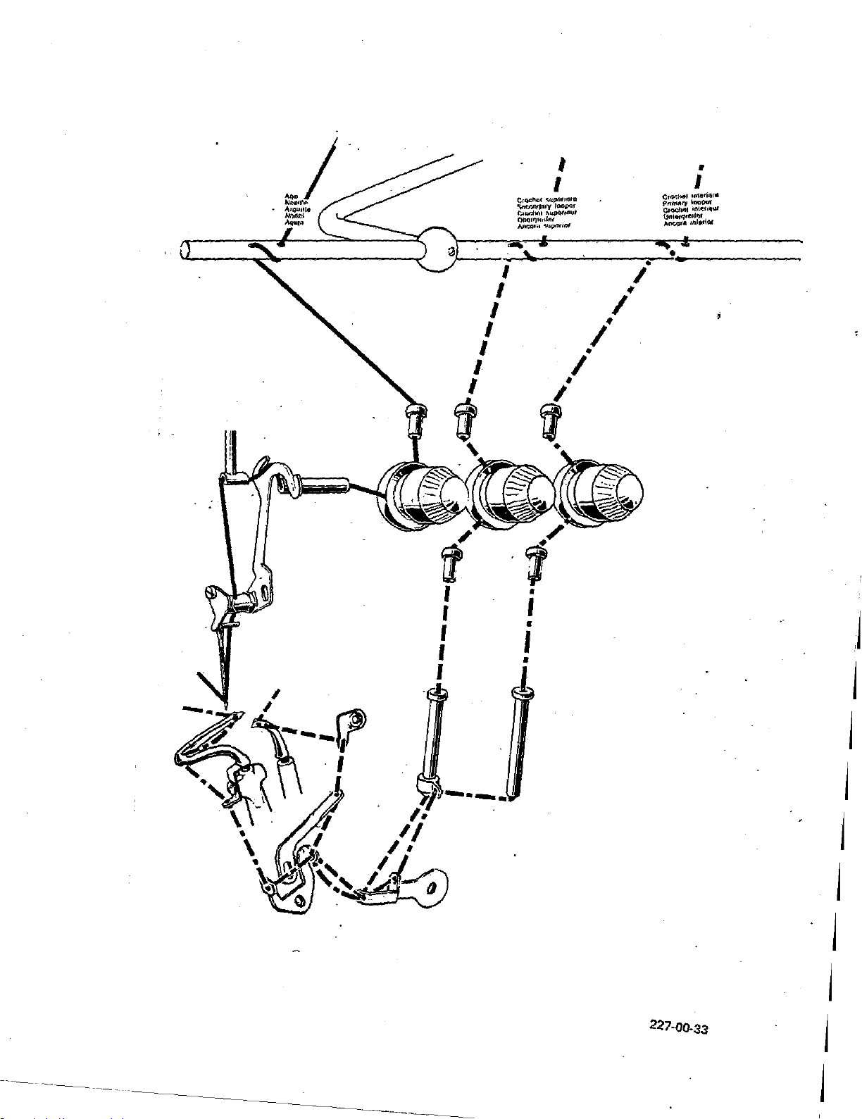
a)
lnfilat11ra
:.
crOCher
~ry
Crochet
Obef'!llreifer
Ancora
IJUJlerior
I
superio,e
,,.,.,
SUJ>eneur
•
•
C~t
inletiore
Primary
lOOPer
~t
Untergreifer
Aneora
inf~Kteur
interior
.I
I
I
I
I
---~
I
I
I
•
I
•
I
•
I
•
227-00-01
221-oo.o2
227-00-04
227-oo.os
227-oo.os
227·00-07
227·00-08
227·00-11
227-00-22
227-00-25
227-D0-26
'227-00-27
227-00-28
227-00-29
227-oo.ao
227-01-01
227-01·02
227-01-03
227-01-04
227-10.02
227-10-03
227-10-04
227·10-0S
227-10-0G
227-10.07
227-11-01
227-17-01
227-22-07
227-22-02
227·22-03
227-22-04
227-22-05
227-23-01
227-23-02
227-23-03
227-23-04
227·23-0S
227-23-0a
227·28-02
227·28-07
227-2a.oa
227-29-01
227-29-02
227-29-03
227-29-04
227-29-os
227-29-0G
227-29-07
227-29-0S
227-30-01
227-30.03
227·30.04
227-30-0S
227-30-06
j
j
j
j
j
j
j
j
j
j
j
j
-
--
----
j
j
Page 20
f'.•nrh111l
PtlmJ!t)'
C•<l(:lnol
\I.,IPI(jf<'IIN
4•u·o'"'
\
\
\
\
\
It
J
J
'
. '
I
•
I
'"'~•or•
lnnper
'"""'II"U
'"""''O'
\
•
;
j
j
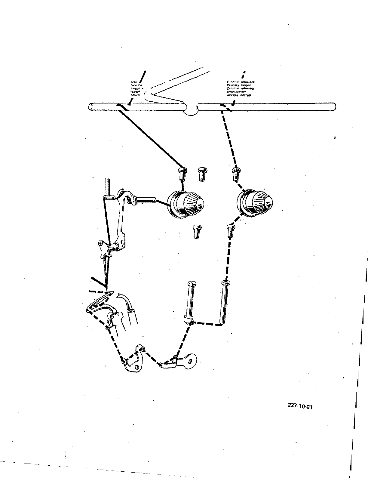
227-10.01
j
j
. j
j
\ j
j
j
j
j
Page 21
I
'
I
I
I
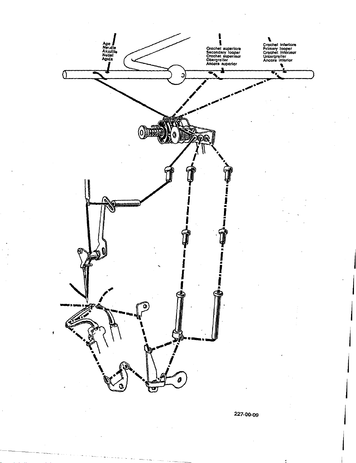
Crochet superior&
Secondary looper
Crochet superieur
Obergreller
Ancora auperlor
\
Crochet lnterlore
Primary looper
Crot;het inf6rieur
UnlergreUer
Ancora inferior
I
I
'
I
'
I
·-·
I
•
I
•
I
•
•
j
j
j
j
j
227-00-09
j
j
j
Page 22
I
I
I
I
I
I
I
~
'
(
I
I
#
I
•
•
I
(:r<Yo!Mtl
u•te•i'llr•
fl'n!l'tltl~
lnal)af
Cl'~
ln\~1...-
tJntowve>IOJr
AIIIOO;If.
11>1111«
! ,
I
•
I
I
I
'
I
•
l
I
•
•
j I
j
j
j
j
j
j
j
------
227-00-33
j
j
Page 23
I
~~
..
~
AigUille .
Nadel
Aguja
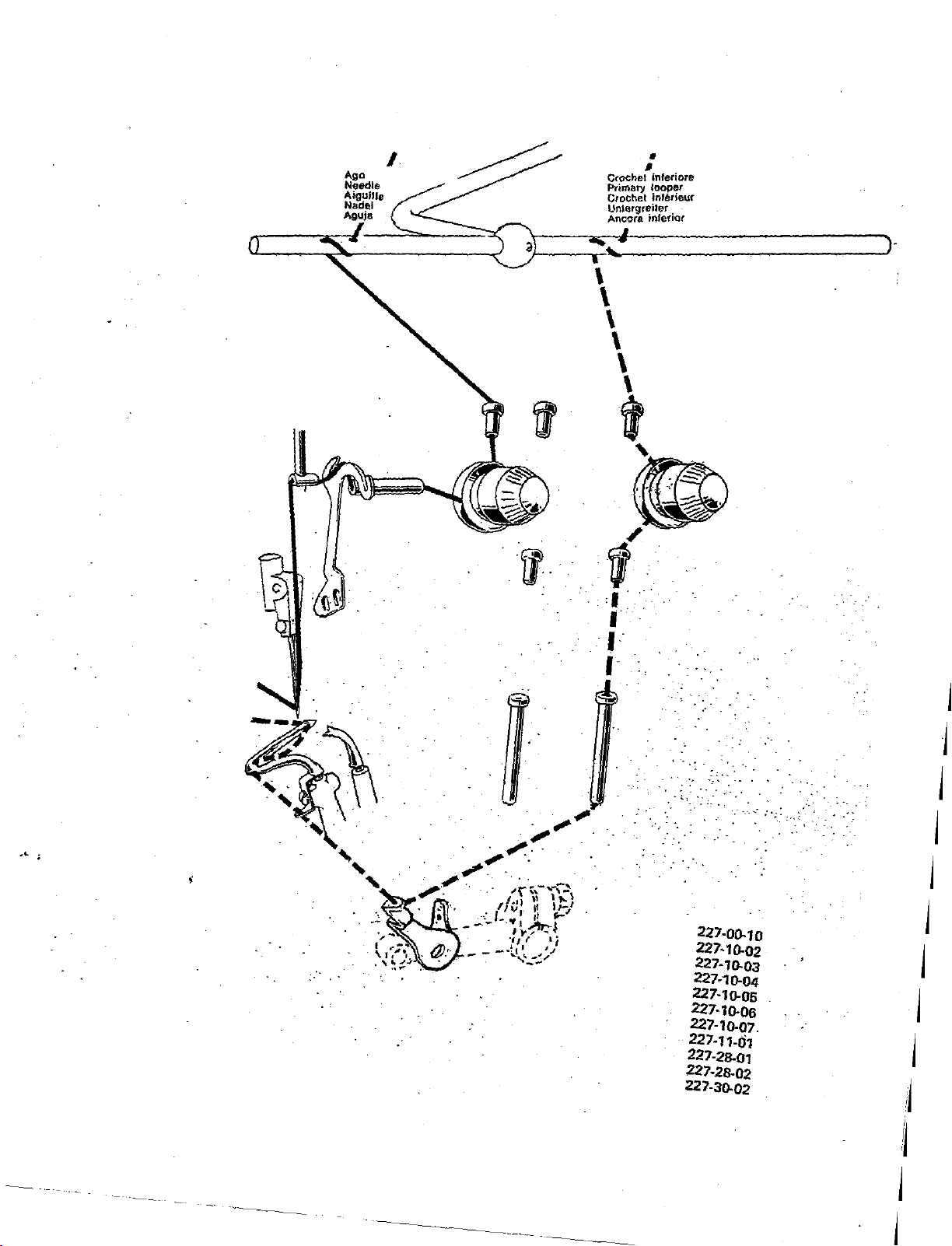
--he!
C
r:-z...
Pnmary • IE!tieur
Crochet
Unlergreiler .
Ancora infenor
\
\
\
\
\
\
t
/
·.
I
•
• •
infer1ore
looper
m
'··
--~
'
....
-,
---
...
.~
~
'
' I
I
. ~.
227-00.TO
227·10.02
227-10.03
227-10.04
227·10.05
227-10.06
227-10-07.
227-11-01
227-28-01
227-28-02
227-30.02
j
j
j
·---
~
:.
:.
j
j
j
j
j
j
:j
---
------
- - ---
--~
1
j
j
Page 24
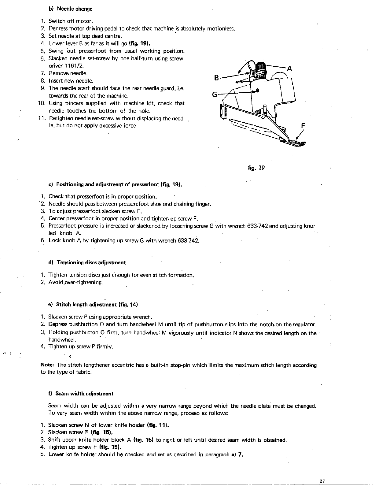
b)
Needle change
1.
Switch off motor.
2. Depress motor driving
3.
Set neadle
4. Lower
5.
Swing
6. Slacken neadle set-screw
driver 1161 /2.
7. Remove needle.
8. Insert new neadle.
9. The neadle scarf should face the rear neadle guard, i.e.
towards
10.
Using
needle touches the bottom of the hole.
11. Retighten needle
but do not apply excessive force
le,
c)
Positioning and adjustment of presserfoot (fig. 19).
at
top dead centre.
lever B
pincers supplied with machine kit, check that
as
out
presserfoot from usual working
the
rear of the machine.
pedal to check that machine
far
as
it
will
go
(fig. 19),
by
one half-turn using screw·
set~screw
without
displacing the need·
_is
pOSitiOn.
absolutely motionless.
fig.
F
19
...
.
1.
Check
that
presserfoot
·2. Neadle should pass between pressurefoot shoa and chaining finger.
3. To adjust presserfoot
4. Center presserfoot
5. Fresserfoot pressure
led
knob A.
6 Lock knob A
d)
Tensioning discs adjustment
1.
Tighten tension discs just enough for even stitch formation.
2. Avoid,over-tightening,
e) Stitch length adjustment (fig. 14)
1.
Slacken screw P using appropriate wrench.
2. Depress pushbutton 0 and turn handwheal M until tip
3.
Holding pushbutton
handwheal.
4. Tighten
Note: The stitch lengthener eccentric
to
the type
by
up
screw P firmly .
of
fabric.
is
in
proper position.
slacken screw
in
proper position and tighten
is
increased or slackened
tightening
up
_0
firm, turn handwheal M vigorously until indicator N shows the desired length on the
F.
up
screw
F.
by
loosening screw G with wrench 633-742 and adjusting knur-
screw G with wrench 633-742.
of
pushbutton slips into the notch on
has
a built-in stop-pin which"limits the maximum stitch length according.
the
regulator.
f) Seam width adjustment
Seam width can
To vary seam width within the above narrow range, procead
1.
Slacken screw N of lower knife holder (fig. 11).
2. Slacken screw F (fig. 15).
3. Shift upper knife holder block A (fig. 15)
4.
Tighten
5.
Lower knife holder should
up
be
adjusted within a very narrow range beyond which the neadle plate must be changed.
screw F (fig. 15).
be
to
checked and set
as
follows:
right or left until desired seam width
as
described
in
paragraph a) 7.
is
obtained.
Page 25
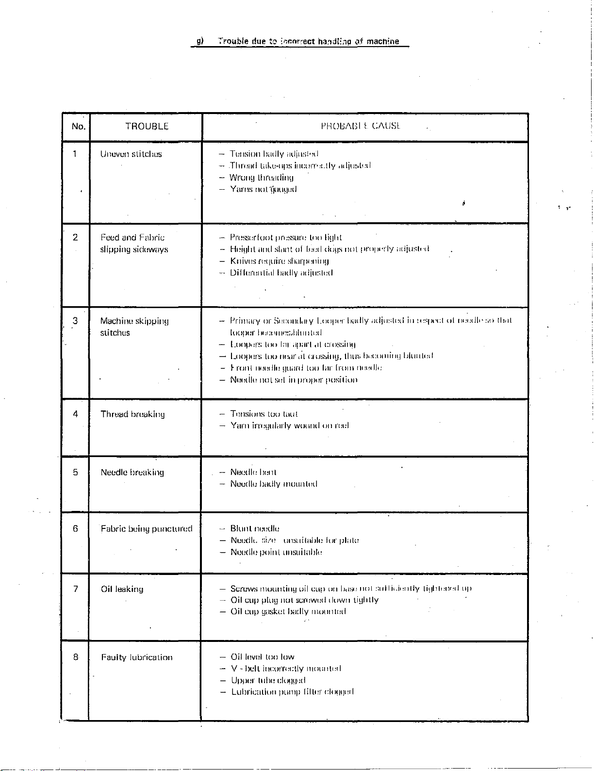
g)
irou:ble
due
t·:J
~r.r.n;-:-ect
ha!ldE;'l!J
of
mach~ne
No.
TROUBLE
1 Uneven
2 Feed and
slipping
3
Machine
stitches
Thmad bwekiny
4
sli
tcllus
Ftlhril:
sidt:ways
skippinu
-
Tw1sion lJiidly
-
Tl Jn:iJcl
-
Wruny
-
Yarns
no
Pn!S.':it:rfuol pn:ssun: l(Jo
-
-
H1:inllt
-
Knivus
..
L)iflufi!Jlli,d
PrilllilfY
·-
IH:t;t
llJOjlt:r
-
l.tHl!J•:n; too l;u .tpart til
I . .IHljlt!I'S LtJO IU:.Jr,it
-
-
~ron!
IJtJI:dlt:
-
Nt:t:dll: tJo\
Tnnsions too
-
-
Yarn
irn:~Julilrfy
rJdjJJ~>i·~tl
lHkt.H
lp!i
llln~e~dill~J
l
TJilli~Jud
<I!Jti
slc~nt
n:quiru
:-illdrpl:lliJIH
hmlly
or
St:t:und,uy
'IIJn:;AJhi!Jit:tl
~JlltJnl
Sid
in
lo•u
int:uiT'
of lt:l:cl
adju:;lt:d
ctw;:-.iJJV,
tuo
prupt:r
l
wound
f'HUll/\lll
::.tly
li~Jht
d<ius
l.tnljH'f
cro:-i~iillq
filr
position
on
n:t!l
t C!\USL
.uljw,lt
:d
not
prnru·rly
[Jadly ildjtJ::tr·d
!Inn;
IJ,:t:tltlliii~J
!nun
ru:t~tiJ;:
.
<Jdjusb·d
i11
!•,.:pt•t:\
!Jillltlt:tl
;
.
oltu·l:tilt·:;n
, .
!ltd!
5 Needle
6
Fabric
Oilleakiny
7
8
Faulty
breaking
being
punctun:d
lubrication
--
NP.1!dl1:
Neudlu
-
-
Blunt
-
Neudlc
-
Nu!:cll1:
- Scn:ws
-
Oil cup pluu
-
Oil
cup
-
Oil
h!vtd too
V
~bell
-
-
Upp1!r
Lubrit.:aliun
-
lu:nl
badly
lllUUlllt!tl
m:t:dlt:
!ii/~!
un~ltilii!Jh:
pointunsuililhlt:
lllutu
1Li11H
nol
scn:wt:d
ym;kutl>aclly 11\ounl!:d
low
im:orn:ctly
Ulill!
clomJI!d
pulllp
lor
uil
cup
tllllllll!t:!l
lillt:r
dn!J!Jt~r[
pltllt!
on
lJdS!!
tluwn
1
HJ
l !ad I
ti~JII
tly
i1.i•
:nlly
li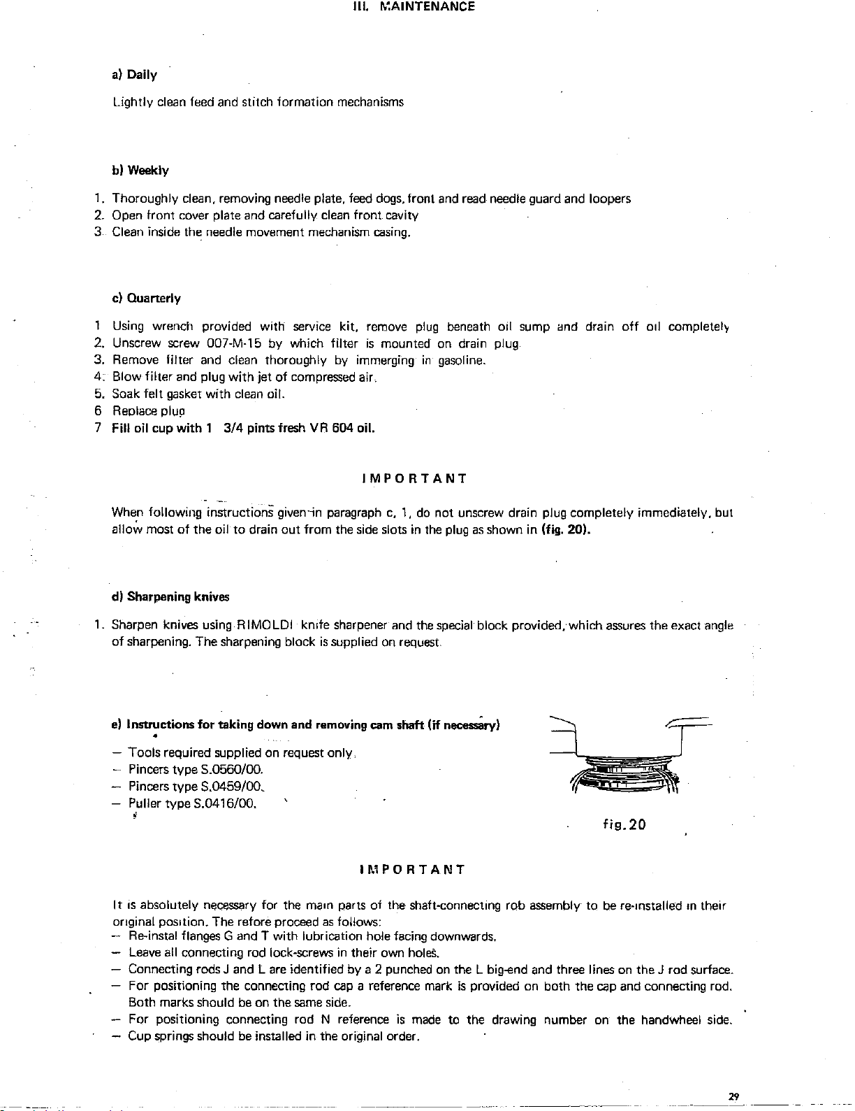
a)
Daily
Ill.
~~AINTENANCE
Lightly
clean
feed
and
stitch formation
mechanisms
b) Weekly
1.
Thoroughly clean, removing needle plate,
2.
Open front cover plate and carefully
3 Clean inside
c)
Ouanerly
1 Using wrench provided
th~
needle movement mechanism
with
service kit, remove
feed
clean
2. Unscrew screw 007-M-15 by which filter
3. Remove filter
4: Blow
5.
filter
Soak felt
6 Replace plup
7 Fill oil cup
and
and
plug
gasket
with
with 1 3/4
clean thoroughly by immerging
with
jet
of
compressed
clean
oil.
pints fresh VR 604 oil.
dogs,
front
front cavity
casing.
plug
is
mounted
in
air.
IMPORTANT
and
read
needle guard
beneath oil sump imd drain
on
drain plug
and
gasoline.
loopers
off
o1l
completel\'
When
following instructions
allo,;,_,
most
of
the oil
to
drain
given
out
d) Sharpening knives
1.
Sharpen knives using R IMOLDI kmfe
of
sharpening. The sharpening block
e)
Instructions
for
taking down and removing cam shaft
•
-Tools
It
anginal pos1tion.
required supplied on request only.
Pincers type S.0560/00.
Pincers type S.0459/00.
Puller type S.0416/00.
IS
absolutely
Re-instal flanges G
Leave
Connecting rods J
necessary
The
for the
retore proceed
and
T with lubrication hole facing downwards.
all connecting rod lock-screws in their own
and L are
For positioning the connecting rod
Both marks should
For positioning
Cup springs should
be
on the
connecting
be
installed in the original order.
in
from
is
paragraph
the
sharpener
supplied
side
c,
1,
slots in
and
on
request.
do
the
IMPORTANT
maon
parts
of
the shaft-connecting rob assembly
as
follows:
holes.
identified by a 2 punched
cap
a reference mark
same
side.
rod N reference
is
made
not unscrew drain plug completely immediately, but
the
plug
as
shown in (fig. 20).
special
(if
necessiiry)
block provided, which
assures
the exact
angle
fig.20
to
be
on
the L big-end and three lines
is
provided on both the
to
the
drawing
number
re-mstalled
on
the J rod surface.
cap
and
on
the
handwheel
connecting rod.
on
their
side.
29
Page 27
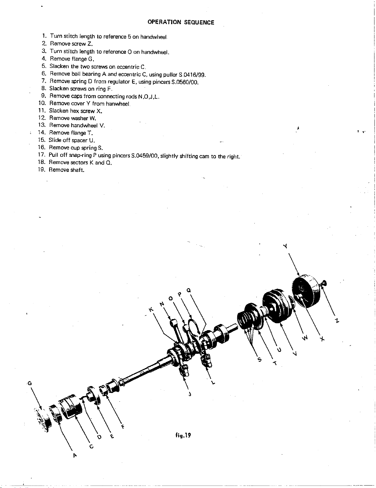
OPERATION
1. Turn stitch length to reference 5 on handwheel
2.
Remove screw Z.
3. Turn stitch length
4.
Remove flange G.
5.
Slacken the
6.
Remove ball bearing A and eccentric
7.
Remove spring D from regulator
8. Slacken screws on ring
9.
Remove
1
0.
Remove cover Y from hanwheeL
Slacken hex screw X.
11.
12. Remove washer
13. Remove handwheel
14. Remove flange
15. Slide
16. Remove cup spring
17.
Pull
18. Remove sectors K and
19. Remove shaft.
caps
off
spacer U.
off
snap-ring P using pincers S.0459/00, slightly shifting
to
reference 0 on handwheel.
two
screws
from
connecting rods N
W.
V,
T.
S.
on eccentric
F.
Q.
C.
C,
using puller S .0416/99.
E,
using pincers S.0560/00.
,0
,J
,L.
SEQUENCE
cam
to the right.
!
,-
fig.19
--···
·-·----·
-----------
---~-
Page 28
-:-··
..=_;;.-_
--~.::
:;~
.
SPARE
PARTS
CATALOGUE
~
~~
-
~-----~---~~
~-~
31
Page 29
a)
Introduction
I. INSTRUCTIONS FOR
USE
1. The Spare Parts Catalogue consists
the
basic machine head and its subclasses.
up
2. For easy
look-up,
3. The conversion groups
4. The
5.
illustrations show
On each illustration the single parts
parts cannot
equipment with the machine but which
the
illustration index shows the position
ot
the basic head and its subclasses are illustrated
the
number identifying subclasses printed
be
supplied separately, are identified
page and illustrated complete with
6. The catalogue carries a general list
machines, with the number of the
ot
a set
of
illustrations
at
the assembly shown are identified
by
can
be
supplied
all
components
of parts
in
at
numerical order
ot
ot
each assembly on
capital letters. Parts and devices which are not standard
on
request are listed at the bottom
the end
ot
by
illustration where the part can
II.
ORDER PLACING PROCEDURE
the different mechanisms or assemblies making
the
machine.
in
individual drawings.
in
bold type
at
top right.
by
a number. Assemblies of which
of
each
illustration
the catalogue
drawing number, covering
be
found.
all
the parts
in
our
a)
All
spare
parts
The following mstruct1ons should be carefully followed to make sure that required spare parts. are shipped
without delay:
1.
State machine
2. State drawing number
3. Write name
head
serial number.
of
spare parts ordered.
of
spare part required
in
full.
4. State quantity required.
IMPORTANT
RlMOLDl are desirous of thoroughly studying
countered with parts they
the spare
b)
1. Only straight
Needles
part· order.
RIM
27 needles should
have
manufactured. For this reason, such parts should
be
used on the machine heads illustrated
all
cases of breakage, wear or unsatisfactory performance en-
be
dispatched together with
in
this catalogue.
2. The needle system and size are marked on the needle shank.
3. The size indicates the average diameter
4. The system and size are also stamped on the
in
hundredths of a millimetre taken on the blade of the needle.
RIMOLDI
needle envelope.
5. When ordering, always state clearly the required needle system and size. (Example:
6.
system
In
case
RIM
27).
of
doubt, attach a sample needle or
an
empty envelope of the needle required.
i. For sewing elastic or elasticised materials special ball-point needles classed as
SKU
are available.
100 needles, size 90,
Page 30
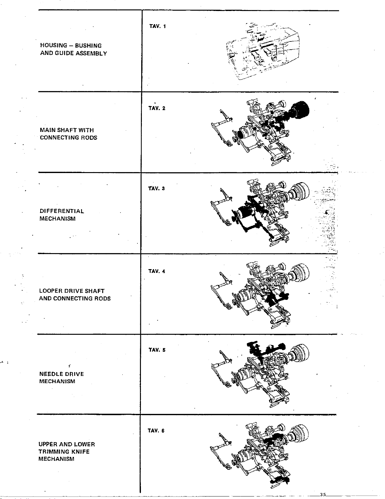
TAV.
1
HOUSINGAND
GUIDE ASSEMBLY
MAIN
SHAFT
BUSHING
WITH
CONNECTING RODS
DIFFERENTIAL
MECHANISM
TAV.
TAV.
,
__
_
'i
___
'
-~
-
---
2
3
.:(
:;
--
->:
.
~~~':}j
..
:<r~~
~;;c-~--
LOOPER
DRIVE
SHAFT
AND CONNECTING RODS
;
NEEDLE
DRIVE
MECHANISM
UPPER
TRIMMING
AND
LOWER
KNIFE
MECHANISM
TAV.
TAV.
TAV.
4
5
6
---
------·--
._35
__
Page 31

Tav. 7
PRESSER
LINKAGE
NEEDLE PLATE
MACHINE COVER
AND WORK PLATE
THREAD
AND TENSION DISCS
OIL
LUBRICATION
SUMP
FOOT
AND
TAKE-UP
AND
PUMP
Tav. 8
Tav. 9
Tav.lO
MACHINE MOUNTING
BRACKET
KNEE CONTROL
REEL STANDS
AND
STANDARD SERVICE
KIT
AND
FOOT PEDAL
Tav.ll
Tav
.12
Tav. 13
;
~
·~1~
lf
1
-
-
-~
-;:::;'
...-:>
e
I
~·
~
'),:·----~-=------
•
..
"'~
~
=¢"
=-~
..
.~-
--
,--
-~-·--
_.._
-.~.
-
"
!
~
,:
""
~
•.
,
~"
'~
~
.1l,.J
I
.
-·
.t~
~
Page 32

HEAD 227-28-01
Tab
14
HEAD 227-10-02
Tab.
45
HEAD
HEAD
HEAD
HEAD
HEAD
HEAD 227-01-02
HEAD 227-00-06
HEAD
HEAD
HEAD
HEAD
HEAD
HEAD
227-28-02. Tab.
227-29-01
227-29-02
227-01-01
227-17-01
227-22-01
227-23-01
227-01-03
227-00-07
227-29-04
227·29-05
15
Tab.
16
Tab.
17
Tab.
18
Tab
19
Tab.
20
Tab.
21
Tab
22 HEAD 227-30-03 Tab. 53
23
Tab
Tab 24
Tab. 25
Tab.
26
Tab 27
HEAD 227-10-03 Tab. 46
HEAD
HEAD 227-10-05
HEAD 227-10-06
HEAD 227-11-01 Tab. 50
HEAD 227-10-07
HEAD 227-00-25
HEAD
HEAD
HEAD
HEAD
HEAD
227-10-04
227-30-04
227-00-26
227-30-05
227-00-27
227-29-08
Tab. 47
Tab.
48
Tab. 49
Tab.
51
Tab.
52
Tab. 54
Tab. 55
56
Tab
57
Tab.
Tab.
58
~~
.
HEAD
HEAD 227-22-02
HEAD 227-22-03
HEAD 227-23-02
HEAD
HEAD
HEAD
HEAD
HEAD
HEAD 227-23-04
HEAD 227-23-05
HEAD
HEAD 227-30-01
227-29-06
227-01-04
227-22-04
227-22-05
227-23-08
227-23-03
227-00-05
Tab.
28
Tab
29
Tab 30
Tab.
31
Tab. 32
Tab. 33
Tab. 34
Tab 35
Tab.
36 HEAD 227-28-08
Tab.
37
Tab. 38
Tab.
39
Tab 40
HEAD 227-00-28
HEAD 227-30-06
HEAD 227-00-29
HEAD 227-00-11
HEAD
HEAD
HEAD
HEAD
HEAD 227-00-08
HEAD
HEAD
HEAD 227-00-33
227-29-07
227-00-09
227-00-10
227·28-07
227-00-02
227-00-30
Tab. 59
Tab. 60
Tab. 61·
Tab. 62
Tab. 63
Tab. 64
Tab. 65
Tab.
66
Tab.
67
Tab. 68
Tab. 69
Tab. 70
Tab.
71
HEAD 227-30-02
HEAD 227-00-04
HEAD 227-10-01
HEAD
227-00-22
Tab.
41
Tab. 42
Tab.
43
Tab.
44
TABLE DEL
PARTS
PARTS
TABLE
ON
FOR
FOR
OF
REQUEST
(100)
W1
(100)
W1
(101)
X1
PARTS SUPPLIED
Tab.
Tab.
Tab.
Tab.
Tab.
Tab.
Tab.
72
73.
74
75
76
77
78
Page 33

,---------------------,
-----~----
1'
I
I
I
I
I
I
·'
REf.
••
1
270-016
2
270-097/1
3
270-058/2
4 270-057{1
5
270-268
5
270-002/1
7
G.270-002/1
PART.
N"
bushiny, needle
bushing,
rear bushing,
front
guide
base,
base
'
DESCRIPTION
bar
knife
looper
looper
looper
~;hi.ifl
holder
shaft
shaft
thread
upper
bushing,
tube.
machine
with
bushings and thread guides
REf.
~
••
0
1
1 9
10
2
11
2
2
12
1
13
1
8 270-912
270-044/2
270-042/3
270-542
270-082/1
270-264
PART.
N''
Jatc:h
pin,
bushing,
bushing
pin,
coverplatfbushing,
thread
work
differential
Oeh),
prt!s•.;erfout
uuitle,
needle
DESCRIPTION
plate
shaft
differential
c:enteriny
lifter
shaft
lever
5i
~
·=
0
.
1
1
1
2
1
1
\
Page 34

227-00-01
20
,.
33
..
lEf.
·N'
1
PM.270-009/4
i2
280-012/3
3
270·116/2
4
270-061/2
270-060/1
.5
,6
270-05911
270-009/4
'7
270-707
8
9
270-613
10
270-709
270-062
11
270-704
12
13
270·705
14
$-620
270-614
15
16
270-008/1
17
270-612/1
18
270-981
19
270-608/5
PART.
N•
----------
DESCRIPTION·
main
shaft,
with
control
rod,
control
rod,
control
rod,
sleeve, secondary looper control rod
sleeve,
primary
main
shaft
ball
bearing,
spacer,
bearing
ball
bearing,
guide,
connecting
snap-ring,
spring,
cup
flange,
right
spacer,
main
handwheel
washer
with
set-screw,
cover
with
connecting
needle
bar
knife
secondary
looper
right 2
left
rod 2
right
ball
shaft
right 1
guide
hanwheel
handwheel
looper
control
bearing
rods
rod
~
~
=
REF.
N'
PART.
N'
"
1
270-310
20
1
21
2:'0-517/2
·no-999
1 22
OlO-H-13,7
2 n
1
24
270-975
1
290-944
1
25
092-D-14
25
1 27 092-C-2 wick
1
28
270-010/2
074-A-12
29
2?'0-722
1
30
290-726
1 31
1
3?
016-D-5 screw,
270-938
33
02.3-!';-5,5
34
1
001-E-10
1
35
1
36
010·0·11,5
PM.270-059/1
1
37
PM.270-060/J
38
pivot,
rockers
screws,
screw
and
screw, sleeve
lock-screw,
oil
bush,
waSher,
ring,
cap,
lock-screw,
grub-screw,
screw,
screw,
sleeve
sleeve
22
DESCRIPTION
lwm.lwheel 1
rocker
for
control
rods
270-115/2
wick,
main
intermediate
differential
odjustment
main
shaft
adjustment
right flonge
looper
assembly
assembly
connecting
intermediate
pin
control
280-012/3
rod
shaft
ring 2
guide
bush
rod
!5
=
"
2
4
4
·-
2
1
2
1
1
1
1
1
2
.:
a
'
..
1
N. B.
Be<JrinHS
supplietl
it
is
indispensable
order
sheet
pearing
moved
reference
us
on
bearing.
number
sep;lrute spares, hOwever
to
Roman
outer
specify
numeral
race
of
the
the
8
1:1.m
on
there-
he
the
ap-
.
Page 35

REf.
H'
PART.
N"
DESCRIPTION
;i
~
0
ltEF.
H'
PART.
N"
--c
1
PM.270-049/1
270-051
2
270-977
3
'
..
-4
270-640/3
5
092-8-1
6
270-937/1
7
270-052
8
270-611/1
'
270-979
9
10
070-M-4,5
11
270-035
12
~030-06
13
270-048
14
073-C-8
15
270-054
16
071-M-5,5
17
279-047/2
18
070-F-4
19
057-F-4
20
270-975
·'
21
22
23
24
25
26
27
28
29
30
31
32
33
34
"5
.·-6
:.7
·.a
::s
·10
41
42
43
44
45
45
--
-
---
270-039
270-7391
071-H-5
270-036/1
270-935
026-C-7
PM.270-038/3
270-040
270-031/1
092-D-6
092-D-12
270-041/1
250-471
017-E-11,5
039-H-9
064-F-5
270·992
270-287/1
07:,3-A-8
PM.270-562.'2
270-288/1
270-567
065-D-6
270-568
270-702
270-703
------·
'
-----------·--
ass~rnbly,
feed
screw,
guide
oil wick
securing
feed
eccentric,
securing
washer,
bush,
collar
link,
washer,
pin,
washer,
guide
washer,
nut
screw,
shaft,
.
sec4ring
washer,
sliding
counter-washer
screw,
complete
yoke,
pin,
oil
oil
rear
screw,
securing
screw,
washer,
screw.
upper
·wilsher,
lever,
stop
sector
washer,
knurled
snap
needle
differentiul
dog,
rear
attach
block,
screw,
dog,
chaining
feed
screw,
differential
differential
differential
pin
differer•ial
dift
.•
segment,
diff.
for
pin
270-054
segment
differential
pin
differential
block,
counter-washer
adjustable
connecting
fork
yoke
wick,
dowel
wick,
rear
pivot,
differential
yoke
screw,
differential
segment
differential
sector
differential
complete
witl-t Sfi!tting
knurled
knob,
ring
roller
rear
feed
righ~
differential
differential
dog
lifter
link
feed
feed
segment
atio
increase
diff.
ratio
pin
eccentric
for
differential
rod
pivot
adjustable
segment
se9ment
differential
marks
knob
lever lock
bearing
slide
dog
eccentric
links
slide
slide
segment
ratio
increase
·
eccentric
differential
eccentric
drive
shaft
control
cage
shaft
assembly
shaft
1
~7
270-037/3
1
48
270-984
49
070-B-3
1
023-N-5,5
1
50
270-735
4 51
1
52
PM.270-045/2
1
53
270-033/1
1
54
270-980
270-943
1
55
2
56
270-034
1
57
005-L-11
1
58
270-997
1
59
270-566/1
1
60
092-0·4
270-978
1 61
1
62
270-050
1
63
290-700
64
270-736/3
1
270-738
1
65
001A-2,5
1
66
1
270-729
67
1
68
279-249/1
1
69
270-250/2
1
70
270-253
004-L-7
1 71
1
72
PM.270-732/3
1
73
270-734
74
1
270-032/3
1
75
004-P-6
1
76
270-928
1 77
270-929
1
78
270-747
1
79
007-C-11 screw,
023-E-12
1
80
1 81
270-595
2
270-717
82
2
83
270-927
1
270-915
84
85
092-0-11
2
1
86
092-D-23 oil wick 1
270-·594
87
1
1 A 270-045/3
T'0-03i:!l3
1 B
279-733!1
c
1
1 D
270-732/3
;
-
DESCRIPTION
.
rod,
differential
~crew,
feed lever 1 -
washer, feed lever 1
.securing screw, pin
eccentric regulation
attachment,
link, differential slide
securing screw, differential link
grub-screw,
bush
for
securing
screw, differential control lever
control
lever,
oil
wick,
securing
front
feed
snap-ring
shank,
pushbutton
spring,
pushbutton
screw
set-screw
shield 1
rubber
guard
gasket,
slide
securing
housing
flat
spring
plate,
differential
securing
grub-screw,
lock-screw,
gib,
eccentric
collar
set-screw,
gasket,
differential
collar,
differential
screw.
collar
plug,
differential
oil
wick
gasket
slide
for
segment
slide,
stitch
stitch
length
------
control
differential
securing
differential
screw
for
differential
differential
screw,
front
dog
for
pushbutton
for
feed
guide
screw,
guard
and
cam
stitch
screw,
cvrsor
for
eccentric
for
grub-screw
slide
eccentric
differential
for
differential
length
eccentric
------------
segment
pushbunon
slide
guide
segment
link
feed
dogs
length
mechanism
plate
slide
control
collar
pinion
bore
adjustment
adjustment
eccentric
cam
dog
lever
cam
eccentric
cursor
------
~-
= =
0
..
1
l
,,
1
1'
1
1
1
2
2
1
1
1
1
1
1
1
1
1
1
1
2
1
1
1 .
2:
2.
2;
1
i
2,
1:
~
I
~I
1
1
.-
1
1
1
--
Page 36

,-
If, .
N'
1
2
3
4
5
6
7
8 250-471
9
10 G .270-065/3
1
12
-
PART.
N'
092-D-16
073-N-10 washers, looper control lever
270-070
270-064
27:277-074
270-075/2
270-069
270-068/3
270-974/1
016-B-4 set-screw,
oil
wick,
pin,
secondary looper control lever
shaft, secondary looper control
secondary looper
primary
shaft,
primary
screw, looper lever
looper-holder,
oscillating guide, with screw-wpe
set-screw, looper
DESCRIPTION
for
pinions
looper
with
with
looper control , 1
primary
primary
looper travel
-
large eye
large eye
bUsh
·,;;
REF.
~
N'
=
a
13
2
14
2
15
1
16
1
17
1
18
1
19
20
.2
1 A
1 8 270-065/3
c
2
1
PART.
N•
016-8-2,5
270-067
~~2-B-1
092-D-7
270-053
016-B-3 set-screw
017-F-11 set-screw
092-C-2 felt tube
70-056/2
270-063/2
D~CRIPTION
grub-screw,
control lever, secondary looper 1
oil-wick,
oil-wick
shim, adjustment
for
for
pin
pin
'
adjustable bush
oscillating guide
looper-holder, secondary 1
On request:
Tab.
27-277-0745
270-D-074/1
270-075
..
..
75
78
75
.
'
~
~
=
.a
1
2
1
1
2
1
4
1
1
Page 37

5
~-
4 \.;;?
\ (
iii
_,
13
21
..
9
10
If;:,
p-
\~
25 19
17
31
REf.
M'
'1
PM.270·138/1
'2 PM.270·137
270·132/1
3
270-728/1
4
·5
290·027/1
270·933
6
270-713
7
270-00511
8
073-F-9
9
10
270-719
11
007-C·11
12
270·007/1
13
;
270-975/1
14
270·03111
15
092-D-6
16
071-E-5
17
001·G·10
18
270-708
PART.
N'
32
/
26
pin, needle lever.rocker
/1
:ever, fork
bush, fork lever
securing screw, bush
washer, needle rocker pin
lock-nut, guide pin
flexible washer
drive shaft, needle !Jar
washer, upper shaft
collar, upper shaft
screw, for collar
attachment,
screw,
attachment
Pin,
,.
attachment
oil-wick, for pin
washer, upper shaft
sc::rew,
washer
bearing,
upper
DESCRIPTION
drive shaft
drive shaft
drive shaft
shaft
!if
KEF.
•
~
H'
~
1
19
'1
20
1 21
1
22
1
23
1
24
25
1
25
1
27
2
2
28
2
29
30
1
1
31
1
32
1
33
1
34
1 A
1 B 290-02511
PART.
250-708/1
016·8·2.5
G.270-025/2
RIM.27 c
003-A-4,5
270·130
092-B-1
016·A·2,5
270·135
092-D·5
27().133/1
023·N·5,5
001·E·7
270·131
092·D·11
092·A-10
270-020/1
N"
DESCRIPTION
needle bearing cage, needle control lever
.
--screw, pin securing
/
needle bar assembly with clamp, complete
needle
screw, needle clamp
pin, needle clamp
oil-wick for needle clamp pin
grub-screw, needle bar clamp pin
lever, needle holder slide control
oil-wick
pin, fork lever
set-screw, needle bar
screw, upper shaft
shim, adjustment
oil-wick, for pin
oil-wick, for
needle clamp
needle
for
bar
pin
control
needl~
~ar
lever
=
"'
•
g
1
1
1
1
1
1
2
2
1
1
1
1
1
1
1
1
1
1
'
Page 38
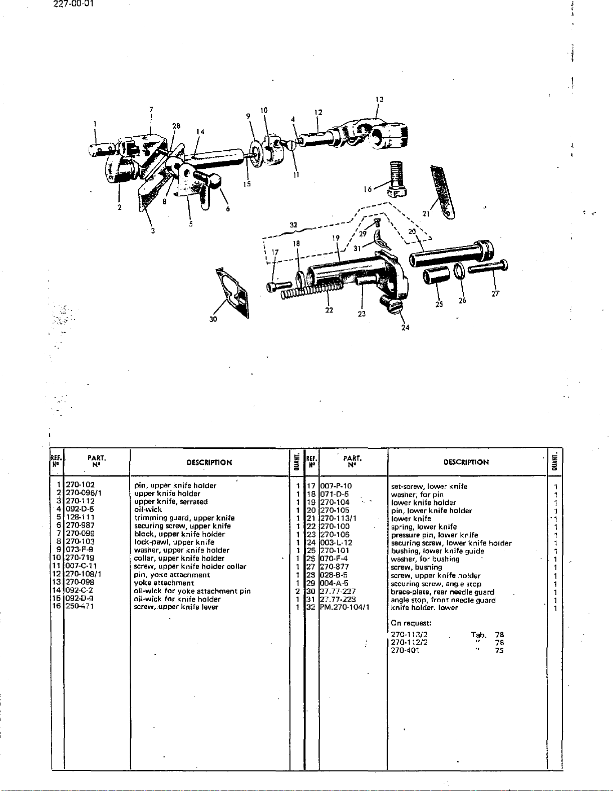
227-00-01
13
, .
.
.-;:.
'
REF.
N•
1
270.102
270.096/1
2
:i
270.112
4
092·0·5
5 128·111
270.987
6
270.099
7
8
270.103
9
073-F-9
10
270.719
11
007-C-11
12
270.108/1
13
270.098
14
092-C-2
15.
092·0·9
16
250471
PART.
"'
DESCRIPTION
pin,
upper
upper
upper
oil-wick
trimming
securing screw,
block,
lock-pawl,
washer,
collar,
screw, upper knife
pin,
yoke
oil-wick for
oil-wick
screw,.upper knife lever
knife holder
knife
holder
knife, serrated
guard,
upper
knife
upper
upper
knife
upper
knife
yoke
attachment
attachment
yoke
for
knife holder
upper
upper
holder
knife
holder
holder
holder
attachment
knife
knife
collar
pin
;;
~
~
~
1
1
1
1
1 21
1
1
1
1
1
1
1
1
2
1 31
1
ilEf.
M'
17
18
19
20
22
23
24
25
25
27
23
29
30
32
PART.
N•
007-P-10
071·0·5
270-104
270-105
270·113/1
270-100
270·106
003·L·12
270-101
070-F-4
270-877
028-8·5
004-A-5
'2.7.77-227
27.77·223
PM.270-104/1
DESCRIPTION
set-screw, lower knife
washer,
for
.
lower
pin,
lower
spring, lower knife
pressure pin, lower knife
securing screw,
bushing,
washer,
screw, bushing
screw, upper knife holder
securing screw, angle
brace-plate, rear needle guard
angle stop,
knife holder. lower
knife
lower
knife
for
pin
holder
knife
lower
bushing
front
lower
knife
On request:
.
270-113/2
270-112/2
270-401
holder
knife
guide
stop
needle guard
Tab.
..
holder
78
78
75
~
~
~
"
1
1
1
1
. 1
1
1
1
1
1
1
1
1
1
1
1
Page 39
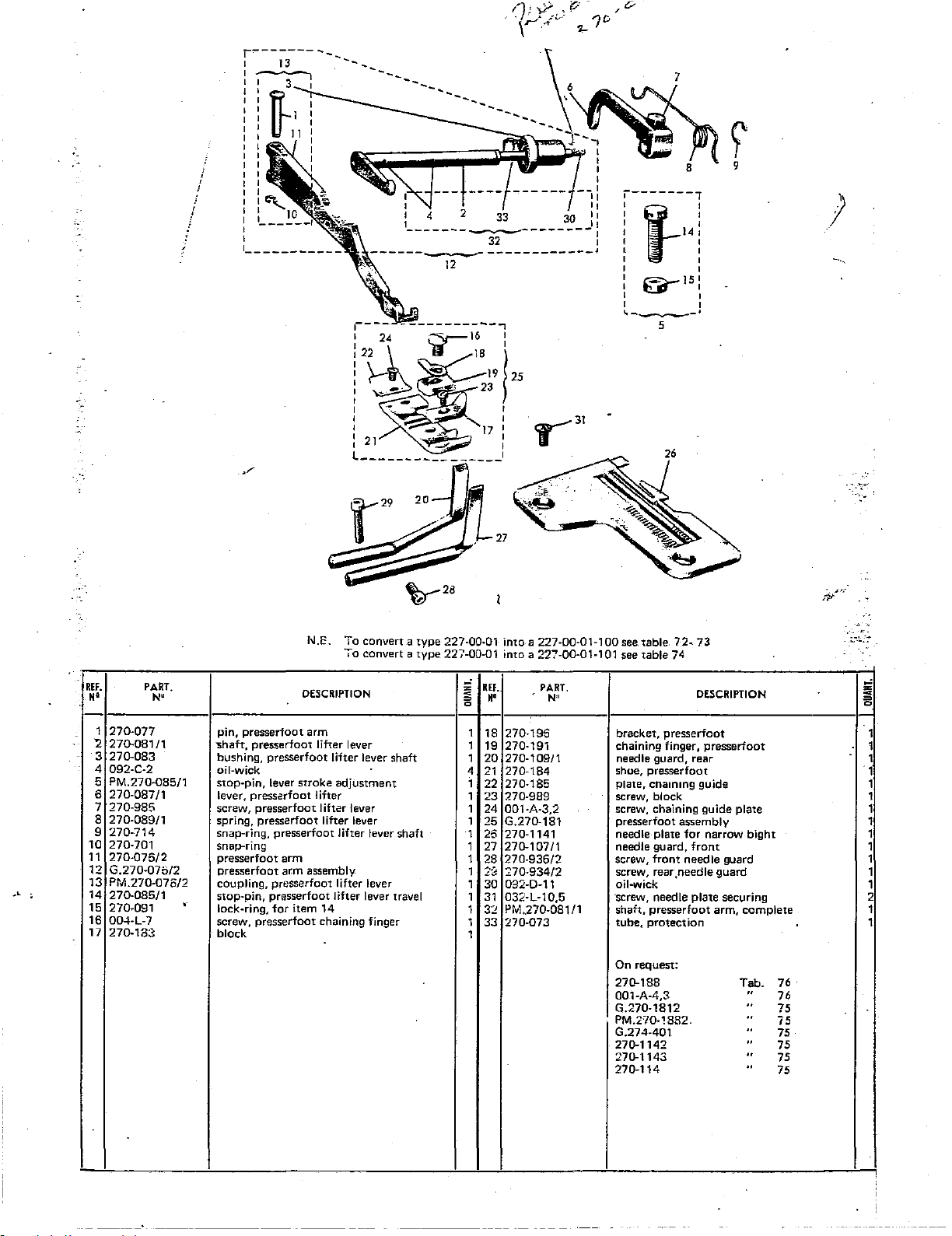
r-------
l
I
I I
I I
I I
1 I
I I
1 I
I I
I I
I I
I I
I I
i
I I
!
'
I I
I I
I
!
!
C\.._
I I 10
I I
____
I
I
1
__________
13
--
...
...
_
30
-1
I
I
I
--I
II
II
::
I
r-------,
1
1-14
I
:
~15
I
I
1,---·
5
)
c:~l
_
_
'----··--·------~-------I
12
REF.
••
1
270-077
2 270-08111
3
270-083
..
4 092-C-2
5 PM.270-085/1
6 270-087/1
7 270-985
8 270-08911
9
270-714
10 270-701
11
270-075/2
12
G.270-076/2
13
PM.270-076/2
14
270-085/1
15
270-091
16
004-L-7
17
270-183
PART.
N•
hi.E. To
To
DESCRIPTION
pin, presserfoot arm
"Shaft,
presserfoot lifter lever
bushing, presserfoot lifter lever shaft
oil-wick
stop-pin,
lever, presserfoot lifter
screw, presserfoot lifter lever
spring,
snap-ring, presserfoot lifter lever shaft
snap-ring
presserfoot arm
presserfoot arm assembly
coupling,
stop-pin, presserfoot lifter lever travel
,.
lock-ring,
screw, presserfoot chaining finger
block
lever
stroke
presserfaot
pr~sserfoot
for
item
liher
14
adjustment
lifter lever
convert a type
convert a
lever
227-00·01 into a 227-00-01-100 see table.
type
227-00-01 into a 227-00-01-101 see table 74
REf.
=
••
0
"
1
18
1 19 270-191 chaining finger,
1
20
4
21
1
22
1
23
1
24
1
25
1
26
1 27
1
28
::·::::
1
1
30
1
31
1
32
33
1
1
PART.
N"
270-195 bracket,
270-109!1
270-184
270-185 plate, cnammg guide
270-989 screw, block
001-A-3,2 screw, chaining guide plate
G.270-181 presserfoot assembly
270-1141 needle plate
270-10711
270-936/2
270-934/2
092-D-11 oil-wick
032-L-10,5 ·screw, needle
PM
.270-081/1
270-073 tube,
needle guard, rear
shoe,
needle guard,
screw,
screw, rear.needle guard
sh;:~h,
On request:
270-188
001-A-4,3
G.270-1812
PM.2'10-1882.
G.274-401
270-1142
270-1143
270-114
72~
73
DESCRIPTION
presserfoot
presserfoot
for
front
front
needle
plate
presserfoot
protection
presserfoot
narrow
bight
guard
securing
arm,
complete
Tab.
..
..
..
..
..
..
..
76
76
75
75
75
75
75
75
;;
~
=
0
1
1
1
1
1
1
1
1
1
1
1
1
1
2
1
1
Page 40

48
13
/'"~
12
_,P
19~~0
0
"·
H'
1
PM.270-208/3
2
007-H-25
3
PM.270-205/3
4
270-241/2
5
270-965/2
6
270-983
!
7
PM.270-218/2
8
l
007-R-7,5
;
9 G
C:10
270-246
'11
270-0£3/1
:12
032-F-9,5
'13
605-412
'14
270-094
;
15
270-701
!16
270-086
:17
270-078
i'18
270-092
270-993
'19
270-995
20
:21
270-065/2
22
270-303
23
026-E-10
24
026-C-7
25
270-247/1
26
PM.270-095/3
27
G.270090/1
28
270-248/1
29
270·940
30
PM.270-210/3
31
270-972
32
270-730/2
.270-220/1
33
34
PM.270-217/2
PART.
N'
.270-245/4
24:-..r----..
DESCRIPTION
side cover,
screw,
cover,
oil-cap,
pacf$ing ring,
screw, cover securing
hinge
screw,
oil-cap
oil-cap
cap,
set4screw,
stop
lever,
snap-ring
spring,
pin.
spring,
set-screw
screw,
plug,
nipple,
screw,
screw, splash
splash Quard
shaft,
release
plug, seal 1
plug,
work-plate
screw-bolt,
screw, plug
pin,
cover,
with
top
with
assembly
securing
plate
plate
spring
cam
presserfoot
presserfoot
presserfoot
presserfoot
top
looper
cover
seal plug securing
pressurcfoot
rod,
screw
front
looper
bushing
cover
thread take-up bushing
with
window
oil-cap
with
oil-cap
gasket
adjustment
stop
cam
locking
release lever
cover
securing
bushing
guard
pressertoot
assembly
machine
cover
plate
and
guide
tubes
plate
release rod 1
pressure
securing
pressure
assembly 1
take-up
~
~
=
a
1
1
1
1
1
1
1
7
1
1
1
1
1
1
1
1
1
1
2
2
1
1
2
1
1
1
1
1
1
1
1
25
RH.
"'
35
36
37
38
39
40
41
42
43
->4
45
45
47
48
49
50
51
52
53
54
55
56
57
58
59
60
61
52
63
64
55
66
57
63
69
PART.
N'
007-F-14
270'221
054-0-4
270-226
G.270-242/3
028-E-10
270-212
001-D-6
001-D-4,5 screw,
270-718
017-E-4,5
270-030
270-973
270-715
270·129/1
270-731/1
;:.:70-231
01205/_.;
270-913
270-214
057-E-4
005-M-10 screw,
270-619
270-624
270-523/1
001-D-10
G.270-216/2
270-030/2
270-1/5
270-174
290-293
270-090/1
271J-110 tie-rod
PM.270-301 sPiasl:lguard
016E45,5
.
31
DESCRIPTION
screw, cover
spring,
front
retaining
complete
bottom
work
plate
spring
spring
workplate
collar
differential
machine
guide
pin
attachment
front
cover
cover
side
side
flange,
left
side
disc
plate
assembly,
front
tensioning
tie-rod
tie-rod
assembly
cover
with
filters,
plate
securing 4
latch
securing
securing
pin
shaft
seal.
assembly,
adjustment
plate
cover
disc
cap
Wtseal 2
plate
securing
plate
left
front
cover
plate
disc
nut,
screw, front cover securing
plate,
screw,
spring,
screw,
collar,
screw,
plug,
screw-bolt,
set-screw for
cap,
plug,
gasket
screw,
pin,
front
set-screw,
nut,
set-screw
flange,
gasket, sealing disc
sealing
screw, sealing
cover
screw, plug
nameplate,
nameplate,
ser-screw,
block,
screw
tubes
short
270-093/1
housing
cover
~
~
=
a
·r
,.
1
1
1
1
1
1
1
1
1
2
1
1
1
1
1
3
1
1
1
3
1
1
1
2
1
1
1
1
1
1
1
1
Page 41
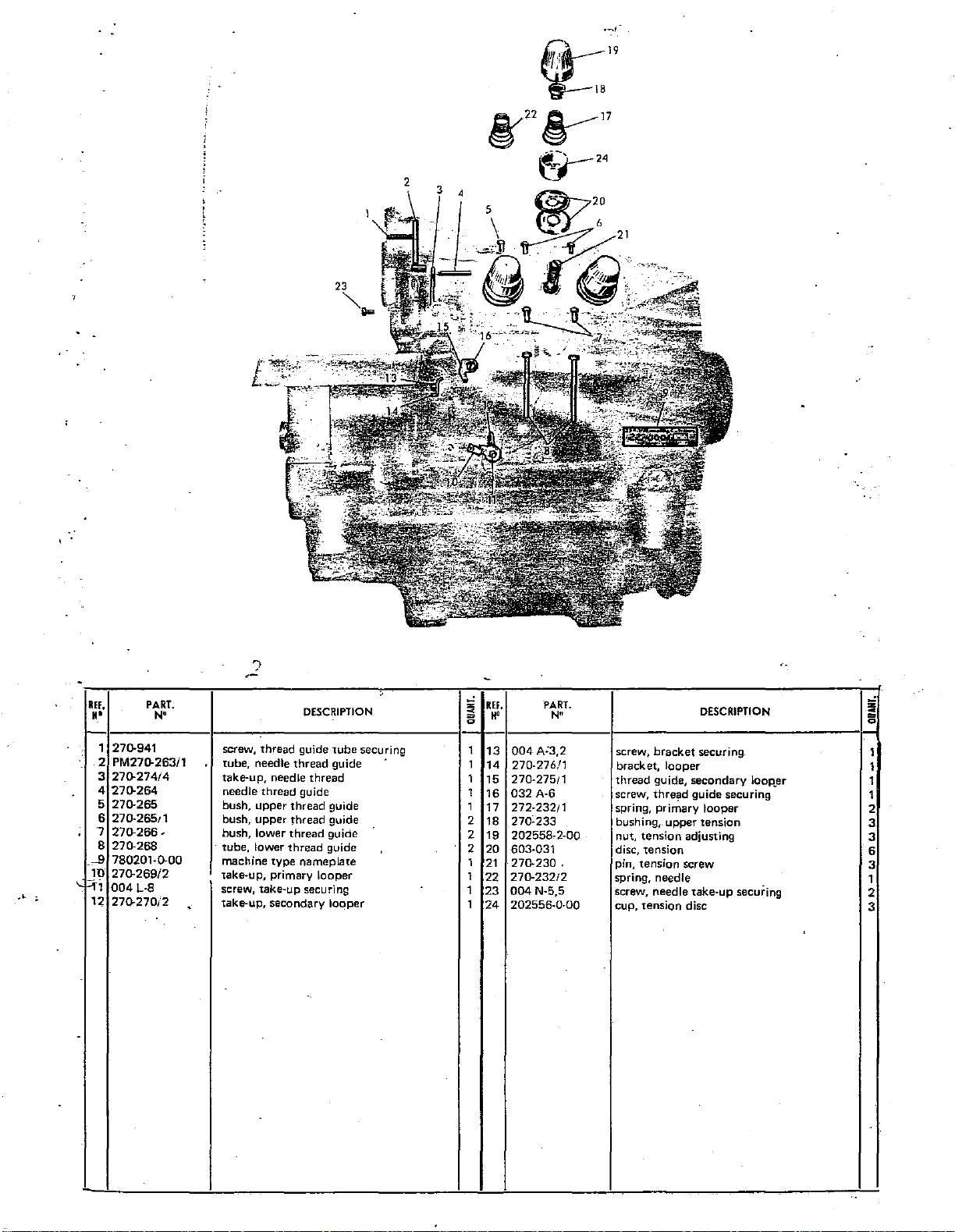
,__,,.
·'
.
REF,
••
1 270-941
2
3
4
5
6
7
8
_ell
1U
~
::;-1
12
-
PART.
N"
PM270-263/1
270-274/4
270-264
270-265
270.26511
270-266'
270-268
780201-0-00
270-269/2
004
L-8
270.270/2
?
screw, thread guide
tube, needle
take-up, needle
needle thread guide
bush,
upper
bush, upper thread guide
bush, lower
tube, lower
machine
take-up, primary looper
screw, take-up securing
take-up, secondary
<
type
DESCRIPTION
tube
thread
guide
thread
thread
guide
thread
guide
thread
guide
nameplate
looper
,_
securing
z
"'
<
=
1
1
1
1
1
2
2
2
1
1
1
1
REF.
H"
13
004
14
270-276/1
27()..275!1
15
16
032
17
272-232!1
270-233
18
19
202558-2-00
20
603-031
270-230
21
22
270-232/2
23
004
202556-0-00
24
PART.
N"
A'3,2
A-6
N-5,5
;;
DESCRIPTION
screw,
bracket
bracket,
thread
screw, thre'!ld guide securing
spring, primary looper
bushing,. upper tension
nut,
tension
disc,
.
tension
pin, tension screw
spring, needle
screw, needle take-up securing
cup, tension disc
securing
looper
guide, secondary
adjusting
IOOP.er
c
=
0 0
1
1
2
3
3
6
3
1
2
3
1
1
Page 42

227-00-01
·(_
IF.
••
1 G.270-816/1 oil
2 G.633-833/1
3 P.M.270-816/1
4
5
6 633-818/1
7 633-711/1
8 270-824/1
9 270-823/1
10
11
12
13
14
15
16
17
18
~~
21
~~
~~
~6
fj~
!29
t:;o
g~
PART.
N'
pump
gear assembly
pump
633-812
PM.633-817/1
633-708
633-707
039-G-10
270-810/2
633-959/1
270-808/1
633-842
270-811/1 pin
270-946
270-947
065-L-5
059-G-6
270-831/1
270-836
017-H-12 grub-screw
007-L-
20
633-966
270-828/1 disc
270-996/2
270-827/1
633-925
G.270-996/2
270-001/2
205520~5·00
unit
screw
cover
washer
gasket
worm
shaft 1
flexible pin
cup spring
screw,
pulley
pulley, oil
oil level
window
gasket
tube
gasket
gasket
washer
nut
tube
felt pad
screw
gasket
plug
felt
disc
spacer
plug, oil sump
oil sump
oil
pump
DESCRIPTION
~ssemiJiy
securing
pump
and sump assembly
complete
REF.
~
=
••
a a
1 34 270-966/1 gasket 1
1
35
1 36 PM.270-645/1 oil distributor
4
37
1 38 270-650
1
39
2
40
41
1
1
43
1
44
45
1
1 46
1
1
1
2
2
2
2
2 54 270-432/1
1 55
1 A
1 a
1 c 533-819 gear
1 D
E 633-818/1
1
1 F 533-83411
1 G 270-816/1 housing,
1 H
1 L 633-813 roller housing 1
1
M·
1
PART.
N'
G.270-646
057-A-3
270-651 gasket 1
270-734/1
270-652 junction tube 1
633-826/1 coupling tube, oil
270-645
016-8-2,5
028-E-10
270-430
633-821/2
633-822/2
633-833
633-814
670-702
DESCRIPTION
oil
distributor
nut
valve
flexible
pointer, oil
grub-screw, pointer
screw
current plug 1
rubber
gear wheel 4
gear wheel pin
plate,
gear plate, inner
washer,
drive
shaft 1
roller housing 1
seal
ring 2
.
asse'"9bly 1
washer
pump
distributor
gasket 1
side
inner
pump
'
~
=
. 1
1"
2
1
1
'
2
1
2
1
T
1
1
1
Page 43

~-
r-
1
I
I
I
I
I
I
I
I
I
I
49
I
I
I
I
I
I
I
I
I
\
I
I
I
I
I
I
I
I
I
I
I
I
I
I
I
I
I
I
I
I
I
I
I
I
\31
I
I
I
I
I
I
I I
\_.,.
I
I
I
__
,...
_____
...J
15
·'
REF.
N'
1
G.270-583
2
270-585
3
059-A-5
4
270-583
5
270-459
6
270-557
7 270-701
8 270-558
9
270-552
10
270-004
1 1
PM.270-005/3
12
.270-588
13
058-M-10
14
057-H-10
15
270-971
16
051-L-10
17
PM.1159
18
G.270-005i3
1S
270-580/1
20
270-584
21
065-L-S
27
059-H-.5
PART.
N"
tie-rod assembly,
coupling,
lock-nut,
rod,
lock-screw,
coupling,
snap-rings
pin,
bushing,
rubber
bearing
guard,
nut,
..
washer,
screw,
nut,
chain
machine
lever,
p1vot,
washer
nut,
...
presserfoot
lifter
presserfoot
flywheel
presserfoot
for
coupling
upper
mounts,
plate,
flywheel
machine
machine
machine
machine
with
hook
bearing
presserfoot
presserfoot
presserfoot
DESCRIPTION
presserfoot
lifter
lever
tie-rod
lifter
lever
guard
lifter lever
plate
machine
with
pins
bearing
screw
bearing
bearing
plate
mounting
plate
....---
lifter
lifter
lifter
lever
plate
plate
lever
lifter lever
lever
upper
bul.t
pivot
llEf.
'"'
=
;;
II'
~
1
1
23
2
24
1
25
7
1 26
3 27
2 28 270-556/1
1
29
30
4
1
31
1
32
8
33
4 34
4
35
4
35
1 37
1
-38
1
39
1
40
3
41
1
42
43
44
45
45
47
48
49
50
51
5:<
53
54
!.l5
'::3
'PART.
N"
270-459
270-558
270-701
270-553
270-554
TS22x35
270-570
038-M-9
005-G-6 set-screw
270-580
2":'0-579
270-998
059-P-8
005-L-11
270-578
270-571
270-720
270-575
270-572
270-575
270-581
270-573
270-574
?.70-582
2":0-577
G.270-570
054-E-5
'270-552
270-577
G.2"/0-556
270-590/1
.<70-590/2
001-G-10
270-589/1
DESCRIPTION
ON
REQUEST
bolts,
chute
pin.
snap-ring
bushing,
spring,
rod,
screw,
base,
screw,
pin,
stop,
screw, knee
nut,
set-screw
knee
shaft,
collar
spring,
coupling,
rocker,
pin,knee
rod.
disc,
pad,
joint,
knee
washer,
bushing,
attachment
rod,
waste
waste
screw,
wus1e
securing
lower
differential
differential
differential
knee
knee
knee
for
knee
knee
control
knee
.knee
knee
knee
knee
knee
knee
knee
control
differential
chute
chute
WilSte
chute-
lever
control
control
control
link 2
control
control
control
screw
push
control
1:ontrol
control
knee
control
control
control
rocker
control
control
control
disc
control
assembly
differential
upper
differential
lever
(long(leftl
chute
short
rod
securing
securing
lever
spring
disc
rod
actuator
actuator
right)
securing
rod
pressure
return
rod
rod
ad
justin
'"'·
'!1·
=
~
9
1
1
1
1
1
4
1
9
2
1
2
2
1
1
1
1
1
1
1
1
1
1
1
1
1
1
1
1
1
1
1
3
1
Page 44

227-00-01
•
j
34
36
40
39
,-
.
I
'
33
I ,
__
If.
••
1
PM.250-133/1
2
016-F-6,5
250-140
3
4
PM.250-148/1
5
250-137
6
250-143
7
250-130
8
G.250-137
1146
9
10
01142
001-G-10
11
001-G-12
12
13
01141
14
AS.250-140
15
270-158/1
16
270-157
G.270-157
18
605-980
"
19
605-937
20
AS.270·140
21
TS.20 x 30
22
569
23
PM.910-914
24
053-H-8
25
910-964
26
910-934/1
27
G.901-914/1·
28
PART.
N'
DESCRIPTION
SUPPLIED
rod,
thread
grub-screw
connector-piece, rod
sustaining
rod,
thread
upright,
upright,
frame,
pin,
thread
plate,
screw,
screw,
base,
thread
thread
"bar,
thread
rod,
thread
bar,
sustaining,
lock-screws
bracket
thread
screw,
pad,
thread
pedal
nut,
pedal
screw,
base,
pedal
pedal
assembly
rod,
main
main
thread
thread
plate
rod
securing
stand
stand
thread
sharp
guide
guide
spool
securing
stand.
guide
guide
spool
WITH
thread
lower
upper
guide (assembly)
spool
assembly
with
assembly
stand
complete
HEAD
guide
sustaining
thread
complete
securing
ONLY
rod (upper)
(lower)
guide
rod
!;i
REf.
~
H'
=
Q
28
2
8
29
1 30 569
1
31
1
32
1
33
1
34
35
1
3
36
1 37
1
38
1
39
1
40
1
1
1
1
3
1
1
2
3
1
2
2
1
1
PART.
N"
409/2
910-143
1145
001·G-10
270-157
016·F·5
270-158/1
605-937
505-980
1145
910-144
G.497
SUPPLIED
thread
spool
upright,
pad,
pin,
cap-screw
rod,
grub-screw
bar, thread
bracket,
lock·s(:rew
lock-nut,
upri~ht,
thread
main
thread
thread
thread
thread
top
guide
thread
DESCRIPTION
W17H STAI•JU
spool
spool
guide
guide
rod
guide
guide
section
assembly
sustaining
rod
sustaining
securiOg
bar
;;
~
=
Q
1
~
5
5
5
1
1
1
1
2
4
2
1
Page 45

t
a
16
j
·o
R
r
\
15
\
14
liEF
-(t'
==4,il;:"liii-?
5
10
I
df
'
13~
·'
l£f,
"'
1
VR.604
2
1175
3
280-155
4
R!M.27
5
1151/2
6
533-742
7
1158
8
641-LY-743
9 1156/1
10
PART.
N'
~
CESCRIPTION
oil, 1 quart
machine cover
vee-belt
needle, RUv1.27
screwdriver
hex.
pincers, threading
hex.
wrench,
can
wrench,
wrench
3/32"
double-ended
1/8",
for
270-715
!0
~
=
0
1
1 11
1 12
5
1
1
1
1 17
1
KEF.
H'
10
270-741
639-M-745
270-113/1
13
270-112
14
01160/2
15
270-745
16
01161/2
270-743
18
270-431
PART.
·N•
pipe-wrench,
wrench
for
kn1fe,
lower
kn:fe,
upper
screwdriver
hex.
wrench,
screwdriver
hex.
wrench,
power
cable and
On request:
270-575/1
DESCRIPTION
9/32"
oil
sump
9/32"
5/64"
plug
plug
Tab.
75
;;i
~
=
0
1
1
1
1
1
1
1
1
1
---------
·-----
---.---
Page 46

227-28-01
1227-00-011
'
24
REF.
H'
1
2 039-R-8,5
3 270-D-074/1
4 G.274-B1-1811
5
6 001-A-3,2
7
8 004-L-7
9 270-191
10
11
12
13
PART.
N"
J-IU
270-1142
270-185
270-196
001-A-5,5
274-81-1921
276-B-184
AS.276-B-403/1
I
l'f6
'!?"'
needle plate, bight width
screw,
guide
looper~
presserfoot assembly
presserfoot chaining
screw, chaining
lug, chaining plate
screw, securing chaining finger
chaining finger
screw, guide retaining
guide
shoe,
guide, swivel
plate securing
eyeless secondary
presserfoot
DESCRIPTION
11/64"
complete
plate
plate
securing
!;i
REF.
~
H'
= 0
1
14
1
15
1
1S
1
17
18
1
19
1
1
20
1
21
1
22
23
.1
1
24
1
25
1
PART.
N"
255-404
PM.275·8-403 guide
G.276-B-403/1
032-F-6,5
605-412
057-E-4
276-3·412
011-E-13
276-8-417/1
276-B-407/1
7804-1
0·0·00
003-M-7
________________
screws
support, complete
screw,
for
eccentric
nut
cup spring
collet screw
bearing
plate,
swivel support
machine
screw, cap
On request:
270075
DESCRIPTION
eccentric
guide
class
plate
J
I
I
I
Tab.
75
!;i
~
= 0
2
1
1
1
1
1
1
1
1
1
1
1
!
-~
Page 47

-·
ltl.
••
1
2 039-R-8,5
3
4 G.274-B1-1811
5 270-185
6 001-A-3,2
7 270-196
8
9 270-191
10
11
12
13
PART.
N'
270-1142
270-D-07411
004-L-7
001-A-5,5
274-81-1921
276-8-184
AS.276-8-403/1
DESCRIPTION
-
needle plate,
screw, guide plate securing
looper,
presserfoot
presserfoot chaining plate
screw, chaining plate securing
lug, chaining plate
screw, chaining finger securing
ch<>'.,ing
screw,
guide
shoe,
guide, swivel
"
bight
eyeless
secondary
assembly
finger
guida
retaining
presserfoot
width
11/64"
complete
g
R!F.
;;
••
1
14
1
15
1
16
1 17
1 18 605-412
1 19 057-E-4
1
20
1
21
1
22
1 23 276-B-40711 swivel support
1 24 780411-0-00 machine class plate
1
1
PART.
N•
255-404
PM.276-B-403
G.276-B-403/1 support, complete 1
032-F-6,5
276·8-412
011-E-13
276-B-417/1 bearing plate, guide
On
request~
screws
guide
screw,
eccentric
nut
cup spring
collet screw 1
for
eccentric
DESCRIPTION
li
;;
2
1
1
t
1
1
1
1
1
270-075
27-277-0745
primary
secondary
looper
looper
Tab.
75
75
Page 48
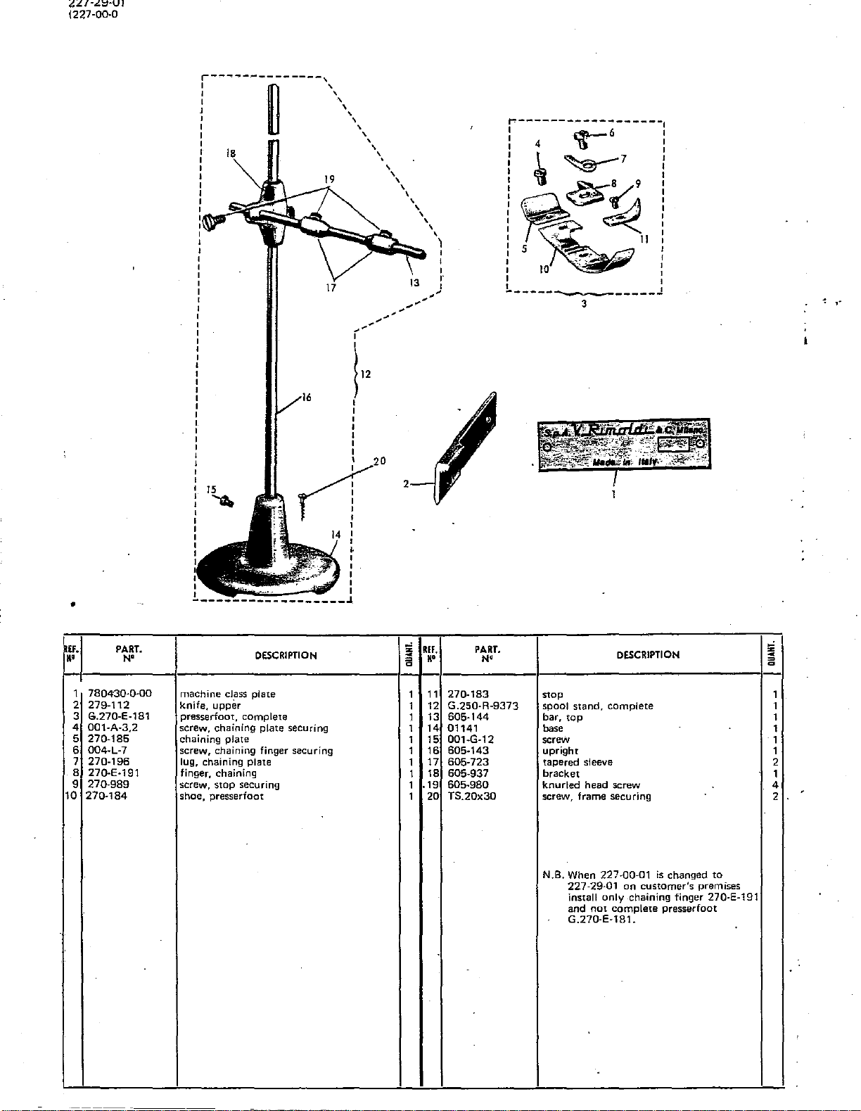
227-29-01
1227-00-0
:---------~------\
I '
I '
J \
I '
I '
17
'
'
'
\
'
'
'
...............
r-
\12
I
I
I
I
I
I
I
'
\
'
13
/
'
'
'
'
---
~------------------,
I
I · I
I
:I
~~,11····
~~
'
I
'
I
I
r
I
I :v·
I 5 ' I
:
I
I I
~------
~6
4 I
~7
..
~~
....
JQ
~I
-~~,.
-·~-·:
.,
- :
_____
3
IJ
I
:
l
:
I
J
"!
,.
•
if.
~·
1
2
3
4
5
6
7
8 27Q-E·191
9
10
PART.
780430·0-00
279-112
G.270-E-181
001-A-3,2
270-185
004-L-7
270-196
270-989
270-184
N'
15
rt20
'a.
--------J.
DESCRIPTION
machine class plate
knife, upper
presserfoot, complete
screw, chaining plate securing
chaining plate
screw, chaining finger securing
lug, chaining plate
finger, chaining
screw, stop securing
shoe, presserfoot
I
I
I
' I
I
I
I
I
~
~
=
a
1
1
1
1 14
1 15
1 16
1
1
.19
1
1
REF.
••
11
12
13
17
18
20
PART.
N•
270-183
G.250-R-9373
605-144
01141
001-G-12
605-143
605-723
605-937 bracket
605-980
TS.20x30
DESCRIPTION
stop
spool stand, complete 1
bar, top 1
base
screw
upright
tapered sleeve 2
knurled head screw 4
screw, frame securing
N.B. When 227-00-01
227-29-01
install only chaining finger 270-E-191
and
not
G.270-E-181.
complete presserfoot
is
on
changed to
customer's premises
z
~
a
1
1
1
1
1
2
Page 49

l-
------
I '
I '
I
I '
I '
I
I '
--u----,',,,
20
',
',.
:---~-------5---:
I , .
:
I
I •
I I
-.
G--3
!2
1
'-------------
'
'
'
'
'
'
'
'
'
'
'
'
r-------------------~
8
;~
1!1.
,.
'
j
1
780431-0-00
2
PM.270-A-267
:
057-A-3
3
4
270-R:267
001-C-5,5
5
6 G.270-EF-181
'
270-185
7
. a
001-A-3,2
9 270-EF-191
1Q
270-196
11
004-L-8
12
270-EF-071
PART.
N"
19
IS
17--o..
yv:---+:-23
I
I
I
I
I
I
I
1 I
~------------------~
DESCRIPTION
plate, machine class
guide, reinforcing tape,
nut
guide,
reinforcing tape
screw
presserfoot,
plate, chaining
screw, chaining
finger, chaining
Jug,
chaining plate
screw
plate
·•
complete
plate
complete
securing
I
22
,_,
z
<
~
g
.
I
1
1
1
1
1
'1.
1
1
1
1
1
IEF.
II'
270-EF-I!i4
13
14
G.250-R-9373
605-144
15
01141
13
001-G-12
17
605-143
18
605.723
19
20
605-937
605-980
21
.279-112
22
TS.20·x·3Q
23
PART.
"
---------~---------
6
.
N"
shoe
elastic reel stand
bar, top
·base, elastic reel
screw.
upright
taper sleeve
. bracket· .
knu'ded head-screw
knife, upper
scre~s.
.
DESCR.IPTION_
-stanc!
frall)e securing
I
I
I
I
I
I
·.
··
.
'·
..
;1
~
i5
'
1
1
1
1
.
"
Page 50

227-01-01
(227-00-01)
,.
------
I
I I
:
37--ij
!
I~
:
:
I
:_
__________
-~
~--··-----1
3~~36
!Cl
~34
-o
38
:
·I
1\32
~
""~-33
.~~j
;
-r1:::i::--a---~-~-----~--
6
~~
T
M'
!f.
PART.
N'
II
ll~
11\
: : 7 23
IL
I
I
I
..
.-
~
. I
9 I
...
-----------------------~
10
I
:
L-------------------------------------~----~--------~
40
'i
39
3
DESCRIPTION
;;
;;
Q
R!f.
M'
PART.
N'
DESCRIPTION
i
=
Q
,.
. 1
G.270-F-401
2
G2701
PD83792
001-E·S
3
'4
270·F·402
5
2726PD802055
G2701PDB4083
6
7
2791
PDB4422
27
,01-P0-444
'8
9
001·C·5,5
10
2701
11
12
13
14
15
16
17
18
19
PDB2232
27.01
-PD-933
27.53-4172
27.53-2201
27.53-4071
27.01-POB-<1012
27.53-4181
27
.01-P0-980
27.53·4251
27.53·4121
0
27.53-4261
guide carrier base
base
screw
shirring
plate
screw
shirring
attachment
push
rod
spring
screw
lever
nut
bearing
plate
latch
pivot
shaft. 1
pawl
nut
screw
washer
screw-nut
mounting
block
27.53·2211
1
21
1
22
039·R·8,5
2"101
2
23
1 24
2
25
1
25
1
27
28
1
2
29
1
30
1
31
}:!
1
1 33 '2"/.01-PD-184 shoe,
1
34
35
1
35
T/
1
1
38
1
39
1
40
PD34083
001-0-7
PM2701P0417/1
PM.270-F-41:3
G2726PD3Cl9375
PM.002-141/1
PM2726PD30
017-E-7
TS.
20 x 30
G.2701-?l'
270-191
270-195
004-L-7
001-.0.-3.7
'27fJ-185 t:huining
780250-0-00
001-E-7
142
nut
screw,
shirring
screw,
angle
fabric
reel
base-plute
plate
grub-screw
wood
presser
finger.
lug,
screw
screw
mm:hine
st:rew,
base
attachment
anglz
stop
guide
stand
with
reel
screw
foot,
presserfoot
chaining
chaining
plute
duss
guide
securing
stop
securing
upright
complete
plate
~lcue
set:uring
housing
1
1
1
1
1
1
1
1
1
1
2
I
•
1
1
'
1
1
1
1
1
Page 51

r-----------,
I
?--12
I
I
:a~
: 7
:c;··-.
I
~-
1
__.
I 9 I
....
10
11
I
'I
I
6
i-----------.J
------------
28
,---=============,,
I
17
""'1~1:"!~21
\.O::L/·Uu-UlJ
i
-·
·-·
REf,
H'
1t"r?.20 xt30.
2 039-.R-8,5
3 270-H-050 '
4
270-H-05~-
270-13-11.4
5
6
G.270d1·181
7 270-185 •
8
om,A-~.2
270-H-184,
9
10
270-196
11
270-H-191
12 004-L-7
13
AS.27D-H-4·13 •
14
G.270;H·41 2
y
r"_--'
I
I
I
I
I
:
~---------------------------------------·
PART.
.N~·
..
scraw, reel stand securing
·
screW, guide securing
feed
dog,
feed
'
·.
·•
"
dog,
needle plate, bight width
presserfoOt,
chaining_
screw
shoe,
.Pre~sertoot
lug, Chaining
chaining
screw
fabric
guide
funnel
guide
DESCRIPTION
front
rear :
COrT:~plete
plate
plate
finger
9/64"-
5/32"
16
,:,
z
IEF.
<
~
II'
g
'15
2
1
16
1 17 032-F-6,5
1 18 605-412
19 057-E-4
1
1
20
1
21
1
22
1
23
1
24
1
25
1
26
1 27
1
28
PART.
255-404
G.276-B-403/1
276-B-412
011-E-13
276-B-41711
276-B-407/1
G2726PDB09375
PM.602-141/1
017-E-7
PM2726PD80142
780340-0-00
N"
screws
bearing block, complete
screw, eccentric
eccentric
nut
cup
spring
caller
screw
bearing
block,
swivel arm
reel stand
base-plate
grub-screw
plate,
complete
machine class
DESCRIPTION
guide
with
upright
plate
;i11
\
<
~
g
2
1
1
1
1
1
'1
1
1
1
1
1
1
1
'
..
·-
·-
Page 52

227-01-02
1227-0Q-01)
,-------------,
I '
I
I '
I '
I
I '
I . '
I
:
I '
I
I
21
~
',
',
',
',
'
(
I
;--~---~~-:
I - .
i 13 .,_,2 I
I I
!
....................................
',
',
'
'
'
'
',
)
I
I
I
I
I
)
'
'
'
'
/
'
'
'
'
'
~----------~---------,
I I
I I
I I
I I
I I
I I
I I
I I
I I
I I
: 5 4 :
I I
I I
I I
I I
I I
'........................
~11
I
...
..................
1
,.
If.
••
1 G.270-R-181
2 '270-185
3
4 270-191
5 270-196
6
7 270-R-071
8 270-R-18!1
9 780251-0-00
10
11
PART.
N'
001-A-3,2
004-L-8
TS.
20 x 30
PM.270-R-267
18
'Q,
-------------
presserfoot,
chaining plate
screw
chaining finger
Jug,
chaining plate
screw
plate
shoe,
presserfoot
machine
wood
screw
tape guide
19
rf1o
7 I
--~'
DESCRIPTION
complete
class plate
!
15
I
I
I
I
I
I
I
I
I
I
I
I
I
I
"'
=
<
~
g
I
IF.
II'
12
1
1
13
14
1
15
1
16
1
17
1
18
1
19
1
20
1
21
2
22
1
PART.
N"
057-A-3
270-R-267
001-C-5,5
G.250-R-9373
605-144
01141
001-G-12
605-143
605-723
605-937
605-980
'
-~··
DESCRIPTION
nut
tape guide
screw
reel stand .
bar,
top
base
screw
upright 1
·taper
sleeve
bracket 1
knurled
heaC
screw
!
~
g•·
1
1
1
1
1
1
1
2
4
Page 53

r--------~
I I
I I
:
I I
I I
I I
I I
I 25 I
I I
I I
I I
I I
I I
I I
:
23
v22:-
:
RIF.
N'
PART.
N'
DESCRIPTION
L1t-,
I . I
I · I
:
6--
·--
21
\
:
-
;;
~
~
=
REF.
N'
PART.
N"
DESCRIPTION
i
l!
1
·'
270·075
G.27.00-8-009/3
2
:<
780206-0-00
.01-P-092
4 27
5
27.01-P-~0311
6
003-A-4,5
7
27.26·186
27.277-0745
8
9 276-B-112
10
277-0501
11
277-0511 feed dog, rear
12
277-052
13
128-110
14
277·113
15
G.277-181
primary
main
machine
spring,
screw, angle
screw, needle securing
presserfoot
secondary
knife,
feed dog,
feed dog, chaining
guard,
knife, lower
presserfoot
looper
shaft
assembly,
class plate
presserfoot
stop
angle
looper
upper
front
upper
complete
pressure
stop
knife
complete
1 16
277-184
1 17 277-191
1 18
270·196
1 19
277-183
20
004-L-8
1
1
21
G.27.77-025/2
016-A-2,5
1
22
1
23
092-A-10
1
24
27.77-020
1
25
290-025/1
1
25
27.77-107/1
1 27
2"1.77-10911
27.77-1141
1
28
1
28.778-07611 lever,
29
1
-
.
shoe,
presserfoot
chaining finger
lug, chaining plate
chaining plate
screw
needle
bar
and
grub-screw
oil wick
needle
needle guide
needle
needle guard,
needle
presserfoot
On
request:
270.075/2
27.277-074
277.050
277.051
27.77-1.142
clamp
clamp
bar
guard,
front
rear
plate,bight
width
7/32"
lifter '
.
Tab.
..
..
..
..
75
75
76
75
76
1
1
1
1
1
1
1
1
1
1
1
1
1
1
Page 54

~:.U·LL-U
227-0Q-061
I
,
.........
,
I
---------------,
I 1
I
I
:
!
0-44
tJ
45\ef
46~
1
1
:
)
:~47r
I-~-
:
'~48
I I
·--
___________
49
I
l
_~
~
~
30
---
'
---
28
I
'
l
t
,.
I
"·
••
1
2 270-701
3
5
6 001-D-7
7
8
9
10
11
12
13
14
~~
h7
'18
.19
20
21
22
23
24
25
26
27
28
29
~0
~i
~3
B4
S5
36
87
PART,
G.270-556
27.01-PD8-558
780360-0-00
PM.297-P08-406
TS.22x35
270-570
038-M-9
005-G-6
270-580
270-579
270-998
059-P-8
005-L-11
270-578
270-571
270-720
270-575
270-572
270-576
270-581
270-573
27Q-574
270-582
270-577
G.270-570
160-030
G.297·PDB-515
297-PDB-402
27.0HDB-518
053-0-4
070-F-4
PM.297-P08-515
270-702
27.01-PDB-517
N"
actuator
snap
ring
stud,
securing
machine
screw,
block
lever,
shirring
screws,
base,
knee
screw,
knee
screws,
pin,
knee
stop,
knee
screw,
knee
nut,
for
screw,
set
lever,
knee
shaft,
knee
collar,
spring
spring,
block,
knee
rocker,
pin,
knee
rod,
knee
knee
disc,
pad,
knee
coupling,
knee
control
pin
for
shirring
shirring
pin,
rear
nut
washer
lifter
lever ,
snap
ring
yoke,
shirring
rod,
class
wood
control
pin
securing
control
control
k~ee
control
control
knee
knee
control
control
control
control
knee
spring
blade
blade
lifter
DESCRIPTION
differantial
-assembly
.
plate
securing
blade
lifter
for
securing
control
mounting
linkage
control
assembly
control
assembly
actuator
main
pressure
control
control
control
assembly
shirring
adjustment
disc
recall
connection
rocker
disc
control
complete
lifter
lever
blac.Je
·
lever linkage compl.ass.
blade
lifter
lever
knee-control
screw
!;i
4
=
a
IEF.
H'
1
38
2
39
1
40
41
1
42
43
1
44
1
4
45
1
46
47
9
2
48
2
49
1
50
51
2
52
2
1
53
54
1
55
1
1
56
1
57
58
1
1
59
1
60
1
61
1
62
1
63
1
64
1
65
1
66
1
67
1
68
1
69
70
1
1
71
1
3
72
1
73
PART.
N"
27.01-?03-519
27
.01-POB-520
297-POi?-401
038-C-7
27.01-P08-516
G.2777-P08-181
004-L-9 screw,
27.77-183
27.77-196
277-191
27.77-POB-184
27.77-PDB-050
27.77-PD3-1 141 needle
27.77-POB-051 feed
PM2701P041711
G.297-PD3-401
297-POB-403
065-L-6
297-PDB-418
004-L-6 screw, shirring
001-E-6
297-PD8-407
297-PDB-408
064-D-5
057-P-5
297-PD8-444
297-POB-442
297-POB-441
028-8-5
270-078
270-094
039-R-8,5
1032
a bushing, shirring
160-032
297-PDB-443
240-035
'
-----
------------
-
--
--
stud,
lifter
pin,
base, shirring
screw,
link,
presserfoot
chaining
lug,
chaining
shoe,
feed
block,
shirring
shaft,
washer
screw, shirring
screw
lever,
block, shirring
washer
nut
spring,
pin,
guide-plate,
screw,
pin,
lifter
screw, shirring
knurled
adjustment
spring,
washer,
On
27.277.074
270.075-2
297-PD3-4021
297-POB-4031
-i --
lever
yoke
secunng
rear
assembly,
chaining
plate
presserfoot
finger,
presserfoot
dog,
front
plate,
dog,
rear
shirring
attachment
shirring
shirring
latch
latch
latch
latch
lifter
lever,
latch
head
shirring
spring
request:
DESCRIPTION
mounting
attachment
complete
finger
securing
securing 1
presserfoot
bight
width
13/64"
attachment
blade
attachment
blade
blade
attachment
latch
pin
pin
guide-plate
attachment
blade
screw, shirring
blac.Je
retainer
assembly
securing 2
pressure
complete
assembly
mounting
securing
securing
pressure
pressure 1
spring
blade
lab
..
..
pressure
75
.
75
76
76
!;i
4
=
a
•
1
1
;
I
;
1
1
1
1
1
1
1
1
1
1
1
~
1
1
4
1
.
1
1
2
1
1
'
1
2
1
1
1
1
1
1
Page 55
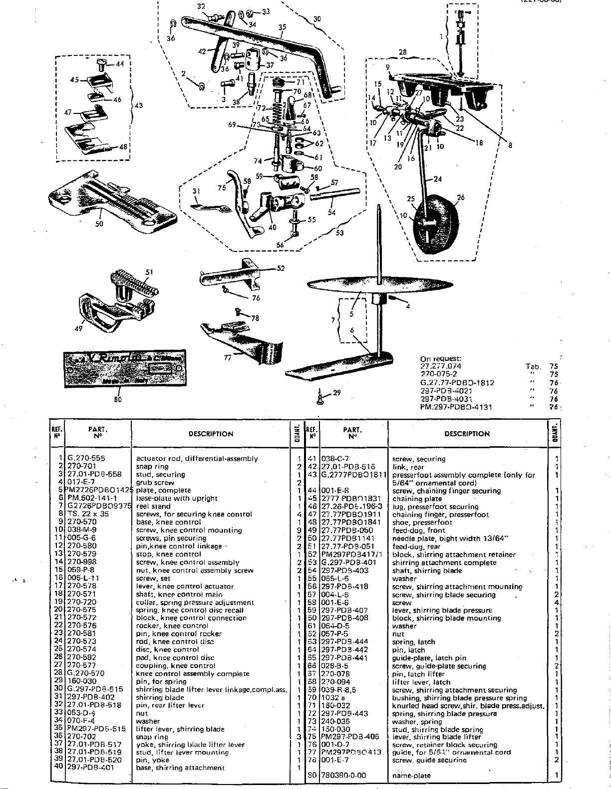
'
'
\,
3~
~~~~~~~~,,~'',,
'
'
42
'
'
'
'
'
'
'
,
28
'
'
'
'
'
'
'
'
'
'
\10
'
'
'
'
'
.._
' I
.-----.
' '
________
'
'
I
'
I
'
I
'
I
'
I
I
'
I
I
I
I
I
I
I
J
!r-29
REF.
••
10
11
12
13
14
15
16
17
18
19
20
21
22
23
24
25
26
27
28
29
30
31
32
33
34
35
36
37
38
39
40
PART.
N'
1
G.270-555
2
270-701
3
27.01-PDB-558
4 017-E-7
5bM2726PDB0142
6 PM.602-141-1
7
G2726PDB0937
8
TS.
:22 x 35
9
270-570
038-M-9
005-G-6
270-580
270-579
270-998
059-P-8
005-l-11
270-578
270-5'"!1
270-720
270-575
270-572
270-576
270-581
270-573
270-574
270-582
270-577
G.270-570
160-030
G.297-PDB-515
297-PDB-402
27.01-POB-518
053-0·4
070-F-4
PM287-PDE>-515
270-702
27.01-PDB-517
27.01-PDB-519
27.01-PDB-520
297-?08-~01
actuator
snap
ring
stud,
securing
grub
screw
plate,
complete
base-alate
reel
stand
screws,
for
base,
knee
screw,
knee
screws,
pin
pin,knee
stop,
knee
screw,
knee
nut,
knee
screw.
set
lever,
knee
shaft,
knef'
collar.
sprmg
spring,
knee
block,
knee
rocker.
knee
pin,
knee
rod,
knee
disc,
knee
pad,
knee
coupling,
knee
control
pin,
for
shirring
shirring
pin,
rear
nut
washer
lifter
lever,
snop
ring
yoke,
shirring
stud,
lifter
pin,
yoke
base,
shirring
DESCRIPTION
rod,
differential-assembly
with
upright
securing
control
securing
control
control
control
control
control
control
control
control
control
knee
spring
blade
blade
lifter
shirring
lever
knee
control
mounting
linkage ·
control
assembly
assembly screw
actuator
main
pressure
control
disc recall
control
connection
control
reeker
disc
disc
contra!
assembly
lifter
lever linkagc,compt.ass.
levt:r
blade
blade
lifter
mouming
attachment
control
adjustment
complete
lever
..,
REF.
z
;::
g
••
41
1
2
42
43
1
2
44
1
45
1
46
1
.;
47
48
1
49
9
50
2
51
2
52
1
2 53 G.297-PDB-401
54
2
55
1
1
56
57
1
.
1
58
59
1
50
1
61
1
52
1
53
1
54
1
55
1
1 60
37
1
58
1
o9
1
70
1
71
1
72
1
73
1
:..:..
1
75
3
76
1
7"7
1
7d
1
1
so
PART.
038-C-7
27.01-PDB-510
G.2777PDB01811
001-E-R
2777
PDBn1831
27
.26-POf=-
27.77PDB01911
27.77PD301841
27.77PDB-050
27.
77PD9
27
.77-PD!3-051
PM297PD3417/1
297'PD9-403
055-L-6
297-PDB-418
004-l-5
001-E-6
297-PDB-407
297-PDB-408
054-0-5
057-P-5
297-PD9-444
297-PD3-442
297-PD3-441
028-8-5
270-078
270-094
039-R-8,5
1032
a
150·032
297-P09-443
240-035
100·030
PM297-PD3-406
001-D-7
?M297P0'30413
001-E-7
780380-0-00
N"
1141
196-3
On request:
27.277.074
270-075-2
G.27 .77-PDB·:J-1812
297-?03-.<1021
297-PDB-4031
PM.297-PDB0-4131
DESCRIPTION
screw, securing
link,
rear
presserfoot
5/64"
screw, chaining finger securing
chaining
lug,
chaining
shoe,
feed-dog,
needle
feed-dog, rear
block,
shirring
shaft,
washer
screw, shirring
screw, shirring
screw
lever, shirring
block,
washer
nut
spring,
pin,
guide-plate,
screw,
pin,
lifter
screw, shirring
bushing,
knurled
spring, shirring
washer,
stud,
lever,
~crew,
guide,
screw.
name-plate
assembly
ornamental
plate
presserfoot
finger,
presserfoot
front
plate,
shirring
attachment
shirring
shirring
latch
latch
guide-plr;~te
latch
lifter
lever,
shirring
head
spring
shirring
sh"1rr"1ng
rewiner
for
guide
bight
attachment
blade
attachment
blade
blade
blade
latch
latch
attachment
screw,shir.
blade
blade
blade
block
5/6-t"
securino
cord)
securing
presserfoot
width
·pressure
pin
securing
blade
spring
ornamental
complete
13/64"
retainer
complete
mounting
securing
mounting
securing·
pressure
blade
pressure
lifter
securing
(only
spring
press.adjust.
cord
Tab.
for
15
75
76
76
76
76·
iii
=
D
1
1
1
1
1
1
1
;
1
1
1
1
1
1
1
2
4
1
1
1
2
1
1
1
2
1
1
1
1
1
1
1
1
1
1
1
2
1
Page 56

:27-01-03
227-00-06)
r------------~
I '
I \
I
I '
r '
I \
I '
I '
I '
I '
I
I '
I '
~
'
\
'
'
'
'
'
'
'
'
-.:;;;;:a
'
~
r------------------,
I 12 - I
11
i
----------~-------~--.
J10
2t-l1·
16
19
I I
I I
I I
I I
I I
L-------------
-~----
15
...
...J
:
:
I
I
I
I
I
l
;)
,Ef.
M'
.
. 1
2
·3
4 01141
5
'6
7
.8
;9
10
)
1
12
'
'
:
PART.
G.250-R-9373
TS. 20 X
001-G-12
605-143
605-144
605-980
605-723
605-937
PM.27.77-R-267
27.77-R-267
001-C-5,5
'
N•
30
1----...,...
-2
I
I
I
I
I
I
I
I
~-====~~---J
DESCRIPTION
spool stand, complete
screw,
wood
screw
base
upright
bar,
top
knurled head screw
steeve
tapered
bracket
tape guide, complete
tape guide,
screw
complete
;i
~
~
=
1 13
2 14
1
1
1
1
4
2 20
1
1 22
1
1
REJ.
M'
15
16
17
18
19
21
23
24
PART.
N•
057-A-3
780-252-0-00
~(277-R-181
04-L-9
~7.77-183
~77-R-184
@7.77·196 lug, chaining plate
1:277-191
~01-A-32
~77-185
27,277-R-071
loo4-G-3 screw
nut
machine
presserfoot complete
screw
chaining plate
shoe,
finger, chaining
screw
plate
plate
DESCRIPTION
class
plate
presserfoot
z
~
=
~
1
1
1
1
1
1
1 .
1
1
1
1
1
l
.
•
Page 57

N.B.
REI.
••
To
convert a
To
convert a
PART.
N"
227-00-07
227-00-07
machine into
machine into
DESCRIPTION
2
227-00-07-100
227-00-07-101
see· tab. 72see tab. 74
z
'""'
<
=
0
73
liEF.
••
3
4-
PART.
N"
DESCRIPTION
'""'
I~
_,
1
270-075
2
27.01-0501
3
780-207-0-00
primary looper
feed dog,
machine class· plate
front
1
4
27.277-0745
1
27.01-1141 needle plate, bight width
5
1
secondary looper 1
On request:
001-D-7
270-075-2
270-401
PM.270-1882
27.01-1143
27.01-1142
27.277-074
G.274-401
9/64"
Tab.
,,
"
" 75
"
"
"
"
75
75
75
,75
75
75
75
1
'
Page 58

Z27-28-U4
227-00-011
,-
4
If.
I'
1 G-27.01-A-181
2
3
4 27.01-0501
5
6
7
8
PART.
N'
27
.01-A-191
270-075
780433-0-00
27.277-0745
G.27.01-A-114
DESCRIPTION
presserfoot
chaining
primary
feed
machine class plate
secondary
needle plate
width
dog,
9/64"
complete-
finger
looper
front
looper
with
presserfoot
guide for bight
!
=
a
1
1
1
1
1
1
1
6
REF.
N'
10
11
12
13
14
8
9
PART.
N'
270-184
270-183
270-989
004-L-7
001-A-3,2
270-185
270-195
;
I
DESCRIPTION
shoe, presserfoot
stop
block
screw,
stop
screw,
screw,
presserfoot
lug, chaining
N.B. When a
block
chaining
chaining
chaining
plate
227-00-07
a 227-29-04
only
supply
27.01-A-191
serfoot_G.27
finger
plate
on
chaining
and
.0
securing
plate
guide
is
converted
customer's
finger
not
complete
1-A-181.
into
premises,
pres-
~
=
a
1
1
1
1
1
1
1
....
....
___
_
Page 59

.----------------\
'
'
'
'
'
'
'
'
~~\
14
12~
I I
L---------------------'
T i "
--------------------
22
'
'
'
'
'
'
'
'
'
'
'
'
'
'
~
23~~-
--------
~21
I
~20:
~
~~18!
:
~:
19!
-~---~'
24 I
7
___
:
j
~·'::~~L.',ft;;i?.
I
I
I
I
I
I
I
I
I
I
I
I
I
I
I
I
I
3
6-
I
4
-·
REF.
I •
H'
1
2
3 27.01-0501 feed-dog,
4
5 27.01-1141
6
7 G.270-E-181 presserfoot,
8 270-E-191
9
10
11
12
PART.
N"
279-112
270-075
780434-0-00
27.277-0745
G.250-R-9373
605-144
01141
001-G-12
knife,
upper
primary
machine
needle plate, bight
secondary
chaining finger, presserfoot
reel
stand
bar,top
base
screw
looper
front
class
looper
complete
DESCRIPTION
plate
width
9/64"
~
=
e
REF.'
H'
PART.
N"
DESCRIPTION
..:I
i.l
:
605-143
I
13
605-723
1
14
.
·-
605-937
1
15
605-980
16
1
TS.
20 x 30
17
1
270-989
18
1
270-183
19
1
270-196
20
1
004-L-7 screw, chaining finger securing
21
1
001-A-3,2
22
1
23
.270-185
1
24
270-184
1
upright
tapered sleeve
bracket
knurled
head screw
screw, frame securing
screw,
stop
stop
lug, chaining p!ate
screw, chaining plate securing
chaining plate
shoe,
N.B.
securing
block
presserfoot
When a 227-00-07
227-29-05
supply
a.nd
G.270-E-181.
on
customer's
only
chaining finger 270-E-191
not
complete
is
convened
presserfoot
into
premises,
1
2
1
;
4
2'
1.
,,
1
1
1
1
1
Page 60

227-29-06
(227-00-011
r--------------.
I
'
'
'
'
'
'
'
'
'
'
'
'
'
'
'
25
'
'
'
'
'
'
'
'
'
'
I
'
I
I
I
I
/
/
/
/
/
/
/
/
/
/
/
/
/
I
I
!
I .
I
I
I
__
ifl------
~~~-
~
8
-----
0-,
...
------.J
9
I
fs
1
J
!
:
,.
22
'
I
I
:
21
'Ill.
I
I
I
I
I
I
I
I
I
I
I I
I
·---------------------~
REF.
N'
i
' 1 270-075
2
3
4
5
i
6
7
8
9
'10
11
12
13
14
PART,
N"
27.01-0501
780435-0-00
27.01-1141
27.277-0745
PM.270-R-267
057-A-3
270-R-267
001-C-5,5
G.270-EF-181
270-185
001-A-3,2
270-EF-191
270-196
----f-26
primary
feed-dog,
machine
needle
secondary
guide
plate,
nut
guide, tape
screw
presserfoot,
chaining
screw, chaining
chaining
lug,
chaining
looper
front
class
plate,
looper
plate
finger
i 18
I
I
I
I
I
I
I
I-
I
I
DESCRIPTION
plate
bight
width
tape
complete
plate
plate
9/64"
securing
~
!i
ll(f.
1
1
1
1
1
1
1
1
23
1
1
1
1
25
1
27
1
M'
15
004-L-8
16
270-EF-071
17
270-EF-184
18
G.250-R-9373
19
505-144
20
01141
21
001-G-12
22
605-143
505-723
24
505-937
25
605-980
TS.
20 x 30
279-112
PART.
N•
s-
'
screw
plate
shoe, presserfoot 1
reel stand 1
bar,
top
base
screw 1
upright
tapered sleeve 2
bracket
knurled
screw, frame securing
knife,
DESCRIPTION
head screw 4
upper
!i
•
= =
Q Q
t F '
1
',
'
I,
1
1
1
~
1
2
1
!
i
I
i
'
'
-
Page 61

:
.46
'lf--48
'
:45-J?l
'
:
:
:~~-,;:..
:
I - '-"\_/7 I
I .
1--~
~=-=
~
~47
:\'-~
\;.,..#--44
~--49
-------~-----·
~
50
I
--·
~
52
53
----~
I
I
'
I
I
I
I
'
I
&
,.,
REf.
=
~
=
g
••
1
39
40
2
1
41
1
42
1
43
44
1
1
45
46
1
1
47
9
48
2
49
50
2
1
51
2
52
2
53
1
54
1
55
1
56
1
57
58
1
1
59
60
1
,.
61
. 1
62
1
63
64
1
..
,.
65
1
66
1
67
1
68
1
69
70
1
1
71
•72
1
l
73
74
75
1
_,
AEF.
••
10
11
12
13
14
15
.16 005-L-11
17
·18
19
20
21
22
n
24
25
26
2•7
:(8
29
3Q
31
32
33
34
35
36
37
38
PART.
N'
1
G.270·556
2
270-701
3
27.01-PDB-558
001-D-7
4
5
PM297P08406
160-030
6
7
240·035
8 TS.22x35
270-570
9
038-M-9 screw, knee
005-G-6
270-580
270-579
270-998
059-P-8
270-578
270-571
·270-720
270-575
270"-572
270'57£
;no-581
270-573
270-574
270-582
270-577_
G.270-570.
297-?08-443
G.197-PbB-515
297-PDB-442
27 .01-PDB-518·
053-D-4
070-F-4
PM.297-PD8-515
270-702
27-.01-PDB-517
27
..
.01-PD8-519
actuator
snap ring
stud,
<Screw,
lever,
pin,
cup,
screws, knee control securing
base,
screws,
pin,
stop,
screw,
_lut,
screw,
_lever,
shaft,
collar, Spring pressure
spring,
block,
~r.ocker;knee
..
plrf,
..
rod,
disc; kriee
pad,
·coupling,
.
knee
spring, shirring blade_pressure
.lifter.lever,
shirring
"pin.
nut
washer
liher
SO<lP
yoke,
stud,
DESCRIPTION
rod,
differential · assembly
securing
retainer
spring
spring
pin
knee
set
knee
knee
hlade
control
control
contrOl
control
control
control
.knee
block securing
blade
control
control
securing
linkage
control
control
assembly·
control
actua!O~
control
control
control
rocker
disc
disc
control
shirring
blade
blade
blade
lever
mounting
lifter
mounting
assembly
screw
adjustment
disc recail
connection
·
complete
compiete
lifter lever 1
aSs.
shirring
for
for
knee
knee
knee
knee
knee
knee.cont.rol main.
knee
koee
knee
Coritrol assembly
·rear·li1'ter lever
lever, shirring
ring 3
shirring
lifter
PART.
N'
27
.01-PD3-520
297-PDB-401
038-C-7
27.01-PD8-516
G.27.01-PD-181
270-185
001-A-3,2
270-196
270'191
004.L-7
27.01-PD-184
27.01-P-050
27.01-P-051
270-075
27.277-0745
780361'0-00
27.01-P:114
PM27
.0.1
G.297-PDB-401
297CPD8-403.
065~L-6
297-PDB'418
004-L-6
001-E-6'.
"297-PD8-407
"297-P.D8-40S
064-D-5
057-P-5.
297-P[Jf.,·'-4~
297-PDB-442.
297-PDB-441
028-8·5
270-078'
270-094
039-R-8,5
1032a.
160-032
PD417/1
DESCRIPTION
pin,
yoke
base, shirring
screw, securing
link,
presserfoot, complete
chaining
screw, chaining plate securing
lug, chaining finger
chaining
screw, chaining
.
shoe,
feed-dog,
feed-dog",
·primary
secondary
machine
needle
·angle
sh.irring
.
shaft
..
~asher
scr.ew. shirri.ng
screw,
screw.
~
lever., shirring
block,
,w~s.her
nut.
spri.nQ, la!ch ·
pin,
latch
·gu'ide-ptate:
screw,
-
pin,
latch
lifter. lever,
screw, shirring
bushing, shirring
stud,
On
request:
27.01~P-114/1
G.27.01-PD-181/1
297-PDB-4021
297-PDB-4031
attachment
rear
plate,
presserfoot
finger,
presserfoot
presserfoot
plafe,
stol?
shirring blilde
sh-_irring
Shi.rr~ng
: . .
guide-plate
shirring
finger
front
rear
I!JOper
looper
Class
plate·
bight
attachment
· · .
attachment
blade
blade
"blade
. -
latch
lifter
latch
attachment
blade
securing
width
complete
securing
pressure
mounting
pin
securing
blade
spring
3/32"
mounting
securing
pressure
Tab.
spring
"
"
75
76
76
76
~I-
~
6
1
. 1
1
1
. 1
j
1
1
1
. 1
1
. 1
1
1
1
1
1
1
1
1
1
1
2
4
1
1
1
2
1
1
1
2
1
1
1
1
1
Page 62

227-22-03
227-00-011
4
,----~
I
1 { !
I
•
73
I
I
I
I 7
,----..1
/
'
'
'
6
'
EF.
N'
2
3
4
5
6
7
8 TS.
9
10
11
12
13
14
15 059-P-8
16
17
18
19
20
21
22
23
24
25
26
27
28
29
30
31
32
33
34
35
36
37
38
PART.
1
G.270-556
270-701
27.01-PDB-558
27.01-P-9-113/1
001-D-7
PM.297-PDB-406
160-030
22 x 35
270-570
038-M-9
005-G-6
270-580
270-579
270-998
005-L-11
270-578
270-571
270-720
270-575
270-572
270-576
270-581
270-573
270-574
270-582
270-577
G.270-570
240-035
G.297-PDB-515
297-PDB-402
27.01-PDB-518·
053-0-4
070-F-4
PM297PDB515
270-702
27.01-PDB-517
27.01-PDB-519
....
\
DESCRIPTION
actuator
snap
stud,
knife,
screw, block securing
lever,
pin,
screws,
base, knee control
screw, knee control mounting
screws,
pin,
stop,
screw,
nut,
screw,
lever,
shaft,
collar,
spring,
block,
rocker,
pin,knee
rod,
disc,
pad,
coupling,
knee
cup
shirring
shirring
pin,
nut
washer
lifter
snap
yoke,
stud,
rod, differentJal - assembly
ring
securing
lower
shirring
blade
f~r
spring
wood,
pin
knee
knee
knee
for
knee
set
knee
knee
spring
knee
knee
knee
control
knee
knee
knee
control
washer,
blade
blade
rear
lifter
lever,
ring-
shirring
lifter
securing ·
control
control
control
control
control
control
control
knee
shirring
lever
for
securing knee
linkage
control
control
pressure
control
control
control
rocker
disc
control
assembly
for
spring
lifter
lever
blade
yoke
lifter
assembly
assembly
actuator
main
adjustment
disc recall
connection
complete
lever linkage
blade
lifter
mounting
lever
control
screw
assembly
;:
REF.
~
M'
= 0
27.01,PD8·520
1
39
297-PD8A01
2
40
1
41
038-C-7
1
42
27.01-PDB-516
43
G.2701-PD9-181
1
270-185
1
44
45
001-ll.-3,2
1
270-196
4
46
1
47 27.01-P-9-191
48
004-L-7
9
2
49
27 .01-PD
2
50
27.01-P-050
27.01-P-051
1
51
270-0'15
2
52
27.277-0745
2
53
1
54
780362-0-00
1
55
27.01-?9-114
PM2701PD41711
1
56
G.297-PDB-401
1
57
297-PDB-403
1
58
1
065-L-6
59
1
28 7-POB-418
60
1
61
004-L-6
1
62 001-E-0
297-?08-407
1
63
64
297-PDB-408
1
1
054-D-5
65
057-P-5
1
66
297-PDB-444
1
67
1
68
297-PDB-4<2
1
297-?08-441
69
1
70
028-B-5
270-078
1
71
1
72
270-094
1
73 0;39-R-8,5
74
3
1032 a
1
75
100-032
1
297-POB-443
76
PART.
....
-9-184
pin,
yoke
base,
shirring
screw, securing
link,
rear
presserfoot,
chaining
screw,
lug,
chaining
chaining
screw,
shoe. presserfoot
feed-dog,
feed-dog,
primary
secondary
machine
needle
block,
shirring
shaft,
waSher
screw,
screw,
screw
lever,
block,
washer
nut
spring,
pin,
latch
guide-plate,
screw,
pin,
latch
lever,
screw
bushing,
stud,
shirring
3pring,
attachment
complete
plate
chaining
plate
finger,
chuining
rront
rear
looper
looper
class
plate,
bight
shirring
attachment
shirring
shirring
shirring
shirring
shirring
latch
latch
guide-plate
lifter
latch
lifter
shirrinq
shirring
blade
shirring
plate
blade
blade
DESCRIPTION
plate
securing
presserfoot
finger securing
width
attachment
3/32"
assembly
attachment
blade
securing
pressu·re
blade
mounting
pin
securing
lever
attachment
blade
pressure
spring
blade
pressure
retainer
complete
rhounting
securinq
spring
=
4
0
=
1
1
1
1
1
1
1
1
1
1
1
1
1
1
1
1
1
1
1
1
1
1
2
4
1
1
1
2
1
1
1
2
1
1
1
1
1
1
On
request:
27.01-P-11.::.
r.;
?7
n1.Pn.1R111
Tab.
..
:'5
Page 63

I
I
45
I d
:
: - .
I
I~·
:
:
1-------------------
~'--
~
£:9
"=:8)
IJ
~47
~-44
·-
:-;...-
~~--49
~~i
~
I
1
\
!
43
53
___
I-
I
9-.-~
I
I
I
;;.:..
___
I
I
I
I
\ 25
I
I
I
I
"
I
L--
1.----,
I 1
1
~
,
___
~
C:£27-UU-Oll
!
:
Jn
request:
27.01-P-114/1
297-PDB-4021
297-PDB-4031
·'
REF.
H'
10
11
12
13
14
15
16
17
18
19
20
21
22
23
24
25
26
27
28
29
30
31
32
33
3<
35
36
37
38
39
40
41
PART.
N'
1
G.270-556
2 270-701 snap ring
3
?7
01-PDB-558
4 PM2726PDB0142!
5 PM602·1·+1'/1
6
G.2726PDB0937!
7
TS.
20 X 30
8 TS.
22 X 35
9
270-570
038-M-9 screw,
005-G-6
270-580
270-579
270-998
059-P-8
005-L-11
270-578
270-571
270-720
270-575
270-572
270-576
270-581
270-573
270-574
270-582
270-577
G.270-570
017-E-7
G.297-PDB-515
297-PDB-402
2701-PDB-518
053-0-4
070-F-4
PM297-POI3-515 lever, shirring bl;3de lifrer
270-702
27
.01-PDB-51.7
27
.01-PDB-519 pin, lifter lever
27.01-PDB-520
297-Pl!>9-401 base. shirring
038-C-7
actuator
stud,
plate,
base
reel
screw, feel
screws, knee
base,
screw,
pin,
stop,
screw, kilee
nut,
screw,
lever,
shaft.
collar,
spring,
block,
rocker,
pin,
rod,
disc,
pad,
coupling,
knee
grub
shirring
shirring
pin,
nut
washer
snap
yoke,
pin,
s;;r::!W,
rod,
securing
complete
plate
stand
knee
knee
pin
knee
knee
knee
set
knee
knee
spring
knee
knee
knee
knee
knee
knee
knee
control
screw
blade
blade
rear
lifter
ring
shirring
yoke
sr=curing
control
control
control
control
control
control
knee
with
stand
control
control
control
securing
control
control
control
control
pressure
control
control
control
assembly
Tab.
DESCRIPTION
differential-
upright
mounting
linkage
assembly
rocker
disc
disc
control
lifter
lever
blade
mounting
attachment
assembly
securing
mounting
assembi y
screw
actuator
main
adjustment
disc
recall
connection
complete
lever linkage assembly
lifter
lever
75
76
76
z
REF.
"'
~
H"
;;:
1
42
2
43
1
2
44
1
45
1
46
2
47
4
'
.
48
1
49
9
50
51
2
52
2
1
53
2
54
2
55
1
55
1
57
1
58
1
59
1
50
51
1
1
62
1
53
64
1
1
65
1
65
1
57
1
58
2
59
1
70
1
71
1
72
1
73
1
74
1
75
3
76
1
77
1
78
1
79
1
80
1
81
82
PART.
N•
27.01-PDB-516
G2701PDBD181
270-185
001-A-3,2
270-196
270-191
004-L-7
27.01 PDBo-184
27 .01-P-050
27.01-P-051
270-075
27.277-07
780381
27.01-P-114
PM2701PD417/1
G.297-PDB-401
297-POB-403
065-L-6
297-POS-418
oo.;-L-6
001-E-6
297-PDB-407
297-POB-408
064-0-5
057-P-5
297-PDB-444
297-PDB-442
29:'-PDB.-4.; 1
028-B-5
270-078
270-094
039-R-8,5
1032
160-032
297-POB-443
240-035
150-030
PM.297-P08-406
001-C-7
PM297PC30413
001-F-7
a
45
-0-00
1-7
DESCRIPTION
link,
rear
presserfoot
ornamental
chaining plate
screw,
lug,
chaining finger, presserfoot
screw, chaining finger securing
shoe,
feed-dog,
feed-dog,
primary
secondary
machine
needle
block,
shirring
shaft,
washer
screw,
screw, shirring
screw
lever, shirring
block.
washer
nut
spring,
pin,
guide-plate,
screw, guide-plate securing
pin.
lifter
screw, shirring
bushing
stud,
spring, shirring
cup
pin,
lever;shirring
screw,
guide,
screw,
assembly
cord
Chaining plate securing
presserfoot
presserfoot
front
rear
looper
looper
class
plate,
shirring
attachment,
shirring
shirring
shirring
latch
latch
latch
latch
lifter
lever,
latch
shirring
shirring
washer, 1or spring
for
spring
retainer
for
5/04"
guide
mounting
.
plate
bight
width
attachment
complete
blade
attachment
blade
blade
pressure
blade
pin
attachment
blade
blade
spring
blade
blade
lifter
block
ornamental
complete
securing
mounting
pressure
pressure
securing
for
3/32"
retainer
mounting
securing
spring
cord
5/64"
-
z
~
=
a
1
1
1
1
1
1
1
1
1
1
1
1
1
1
1
1
1
1
1
2
4.
1
. 1
2
1
1
1
1
2
1
1
1
1
1
1
1
1
1
1
1
2,
----
Page 64
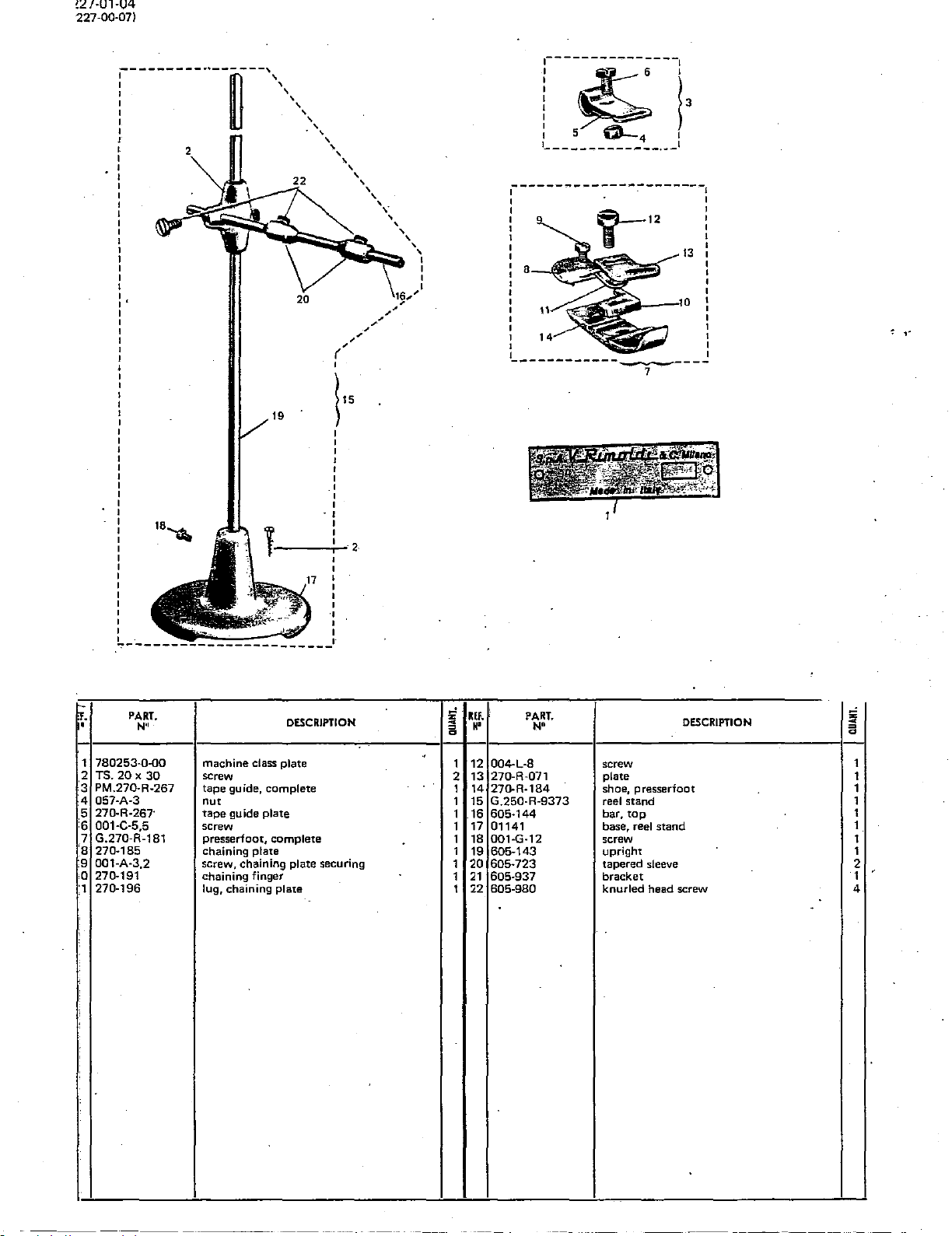
!27·01·04
227·01J.07)
~----~--l
18~
19
----i--2
~15
I 5
1_
____________
~--------------------~
I I
I I
I I
I I
I I
I I
I I
: a :
I I
' '
' '
'
I I
I I
I I
L___________
0-
I
4
,
__
1
' I I
I
7
,.
~.
•
1
2
3 PM.271J.R·267
4 057·A·3
5 270·R·267·
6 001·C·5,5
7 G.270·R-181
'8
9 001·A·3,2
0 271).191
:1
PART.
N''
780253.().()0
TS.20x30
270·185
270·196
DESCRIPTION
machine class plate
screw
tape guide, complete
nut
tape guide plate
screw
presserfoot,
chaining plate
screw, chaining plate securing
chaining finger
lug, chaining plate
complete
.
lEI.
1i
=
••
a
1
12 004-L·8 screw
2
13
14
1
1
15
1
16
17
1
18
1
1
19
1
20
1
21
22
1
PART.
N•
270·R·071 plate 1
271J.R·184
G.250·R-9373 reel stand
605·144
01141
001·G·12 screw 1
605-143 upright 1
605·723
605·937
605-980 knurled head screw 4
shoe, presserfoot 1
bar,
tap
base, reel stand
tapered sleeve
bracket
DESCRIPTION
;;;
•
=
a
1
1
1
1
2
1
'
------
Page 65

(227-00-01)
,--------·
~-
I
:45-.l\j
'
:
(~~~
1~44
~-----,
46
~··-.....-:-.
~
~47
48
:
I
:
l
43
~...-
' '
I
'
I
'
1---------~------·--
~---
~-
~
·.·
''-/7
~·
50
~
.
'
i
;t:.'-.:~·
' i
>f;J
51
'
'
'
'
'
/ 6
'
31
~~~
...............
',
55
.-
-~
-~
'
'
I
I
'
I
'
8
'
'
'
'
'
'
'
'
'
'
'
'
'
'
'
L--
53
~
-~
PART.
N'
G.270-556
270-701
27
.01-PDB-558
780363-o-oo
001-D-7
PM.297PDB406
160-030
TS.
22 x 35
270-570
038-M-9
005-G-6
270-580
270-579
270-998
059-P-8
1•
005-L-1
270-578
270-571
270-720
270-575
270-572
270-576
270-581
270-573
270-574
270-582
270-577
G.270-570
240-035
G297-PDB-515
297-PDB-402
27.01-PDB-518
053-D-4
070-F-4
PM297-PD8515
270-702
27
.01-PD8-517
27.01-PDB-519
DESCRIPTION
actuator
snap
stud,
machine
screw, block securing
lever, shirring blade lifter
pin,
screws,
base, knee
screw, knee
screws,
pin,
stop,
screw,
nut,
screw,
lever, knee
shaft,
collar, spring pressure
spring,
block.,
rocker,
pin,
rod,
disc,
pad,
coupling,
knee
cup
shirring
shirring
pin, rear lifter lever
nut
washer
lifter lever, shirring blade
snap·ring
yoke,
stud,
rod,
ring
for
knee
for
knee
knee
knee
knee
control
washer, spring
differential
securing
class
spring
wood
for
control
control
pin
securing
control
knee
control
knee
control
knee
control
set
control
knee
control
knee
control
knee
control
knee
control
control
control
control
control
knee
assembly
blade
blade
shirring
lifter lever
plate
control
lifter lever linkage assembly
blade
yoke
securing knee
mounting
linkage
assembly
assembly screw
actuator
main
adjustment
disc rec:all
connection
rocker
disc
complete
lifter lever
mounting
assembly
control
-·
REf.
N'
1
2
3
4
5
6
7
8
9
10
11
12
13
14
15
16
17
18
19
20
21
22
23
24
25
26
27
28
29
30
31
32
33
34
35
36
37
38
-'
~
REF.
<
N'
=
a
1
39
2
40
1
41 038-C-7
1
42
43
1
1
44
45
1
46
4
47
1
9
48
2
49
2
50
1
51
52
2
2
53
·1
54
1
55
1
56
1
57
1
58
1
59
1
60
1
61
1
62
1
63
1
64
1
65
1
66
1
67
1
68
1
69
1
70
1
71
1
72
1
73
3
74
1
75
1
PART.
N
27.01-PDB-520
297-PDB-401
27 .01-PDB-516
G.27.01PD181
270-185
001-A-3,2
270-196
270-191
004-L-7
27.01-PD-184
27.02-P-050
27.02-P-051
270-075
27.277-0745
27
.03-P-114
PM2701PD417/1
G297·PDB401
297-PDB-403
065-L-6
297-PDB-418
004-L-6
001-E-6
297-PDB-407
297-PDB-408
064-D-5
057-P-5
297-PDB-444
297-PDB-442
297-PDB-441
028-8-5
270-078
270-094
039-R-8,5
1032/a
160-032
297-PDB-443
-
DESCRIPTION.
pin,
yoke
base, shirring
screw. securing
link,
rear
presserfoot,
chaining
screw, chaining
lug, chaining
chaining finger,
screw, presserfoot chaining finger mounting
shoe,
feed-dog,
feed-dog, rear
primary
secondary
needle plate,
block,
shirring
shaft,
washer
screw, shirring
screw, shirring
screw
lever, shirring
block,
washer
nut
spring, latch
pin, latch
guide-plate, latch
screw, guide-plate securing
pin, latch lifter lever
lever, latch lifter
screw, shirring
bushing,
stud,
spring, shirring
On request:
G.27
.01-PD-181/1
297-PDB-4021
297-PDB-4031
attachment
complete
plate
plate
presserfoot
front
looper
looper
bight
shirring
attachment,
shirring
blade
blade
shirring
shlrring
shirring
blade
plate
mounting
presserfoot
width
attachment
complete
attachment
blade
securing
pressure
blade
mounting
pin
attachment
blade
pressure spring
spring
blade
pressure
3/32"
retainer
mounting
securing
Tab.
76
7'6
..
70
~
=
a
1
1
1
1
1
1
1
1
i
1
1
1
1
1
1
1
1
1
1
1
1
2
4
1
1
1
2
1
1
1
2
1
1
1
1
1
1
Page 66
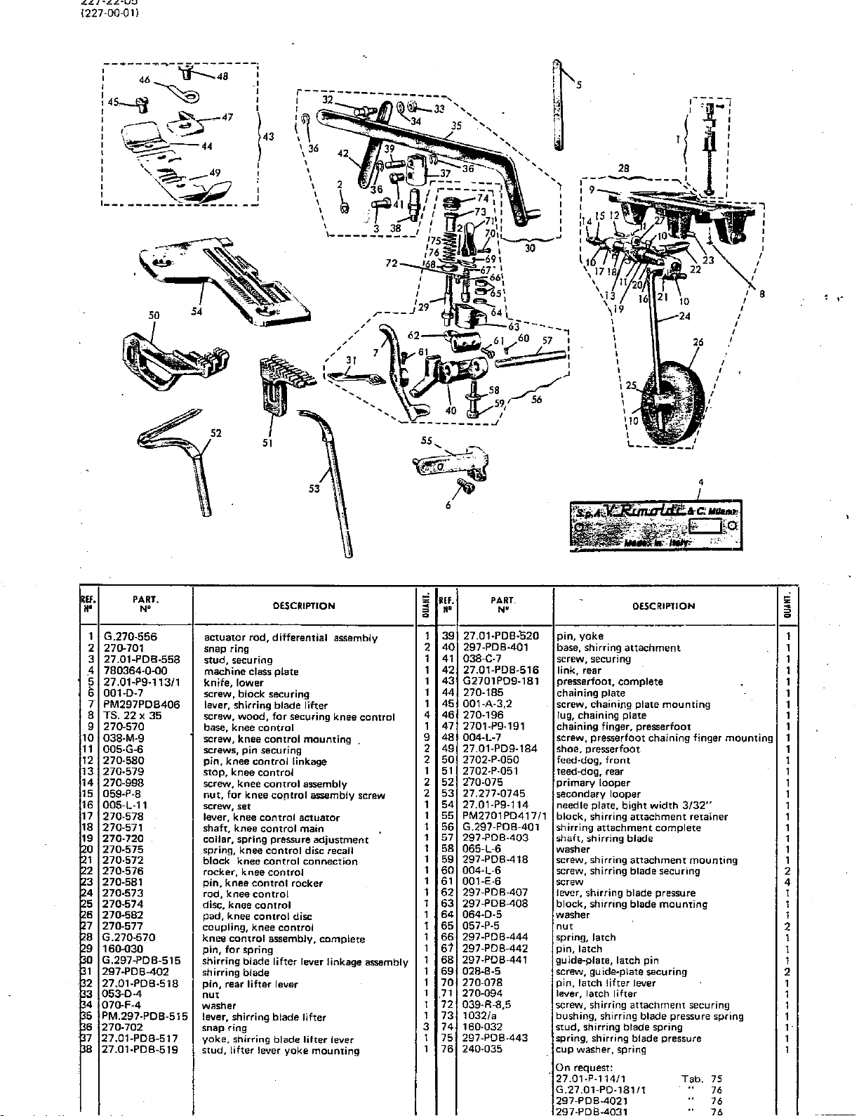
44/~L.L~u;,;
1227-00-011
5
53
REF.
H'
1
2
3
.4
~
7
8 TS.
9
10
11
12
13
14
15
16
17
18
~?
~~
~~
§~
~~
~~
~3
~~
~~
~~
PART.
N'
G.270-556
270-701
27.01-PDB-558
780364-Q-00
27.01-P9·113/1
001-D-7
PM297PDB406
22 x 35
270-570
038-M-9
005-G-6
270-580
270-579
270-998
059-P-8
005-L-11
270-578
270-571
270-720
270-575
270-572
270-576
270-581
270-573
270-574
270-582
270-577
G.270-570
160-Q30
G.297-PDB-515
297-PDB-402
27.01-PDB-518
053-0-4
070-F-4
PM.297-PDB-515
270-702
27.01·PDB-517
27.01-PDB-519
actuator
snap
stud,
machine
knife,
screw,
lever,
screw,
base, knee
screw, knee
screws,
pin,
stop,
screw, knee
nut,
screw, set
lever, knee
shaft,
collar,
spring, knee
block
rocker,
pin,
rod,
disc, knee
pad, knee
coupling,
knee
pin,
shirring
shirring
pin,
nut
washer
lever,
snap
yoke,
stud,
rod,
ring
securing
class
lower
block
shirring
wood,
pin
knee
knee
for
knee cOfltrol assembly screw
knee
spring pressure
knee
knee
knee
control
knee
knee
control
for
spring
blade
blade
rear
lifter
shirring
ring
shirring
lifter
DESCRIPTION
differential
plate
securing
blade
for
control
control
securing
control
control
control
control
control
control
control
control
control
control
control
control
assembly,
lifter
lever
blade
blade
lever
yoke
assembly
lifter
securing knee
mounting
linkage
assembly
actuator
main
adjustment
disc
recall
connection
rocker
disc
complete
lever
linkage
lifter
lifter
lever
mounting
control
assembly
;;
REF.
~
=
••
0
1 39 27.01-PDB-"520
40
2
1
41
42
1
43
1
1
44
1 45
4
46
1 47 2701-P9-191
48
9
49
2
2
50
1
51
2 52 270-075
2 53 27.277-0745
1 54 27.01-P9-114
1 55 PM2701PD41711
1 56 G.297-PDB-401
1 57
1 58 065-L-6
1
59
1
60
1
61
1 62
1
63
1
64
1 65
1
66
1
61
1 68
1 69
1
70
1
71
1
72
1
73
3
74
1 75
1
76
PART.
N'
297-PDB-401
038-C-7
27.01-PDB-516
G2701PD9-181
270-185
001·A·3,2
270-196 lug, chaining plate
004-L-7
27.01-PD9-184
2702-P-050
2702-P-051 teed-dog, rear
297-PDB-403
297-POB-418
004-L-6
001-E-6
297-PDB-407
297-PDB-408
064-D-5
057-P-5
297-PDB-444
297-PDB-442
297-PDB-441
028-8-5
270-078
270-094
039-R-8,5
1
032/a
160-032
297-POB-443
240-035
4
-
pin,
yoke
base,
shirring
screw, securing 1
link,
rear
presserfoot,
chaining
screw, chaining plate
chaining
screw, presserfoot
shoe. presserfoot
feed·dog,
primary
secondary
needle plate,
block,
shirring
shirring
shaft,
shirring
washer
screw, shirring
screw, shirring blade securing
screw
lever,
shirring
block,
shirring
washer
nut
spring,
pin,
latch
guide-plate,
screw, guide-plate securing
pin,
latch
lever, latch
screw, shirring
bushing, shirring blade pressure spring
stud,
shirring
spring, shirring
cup
washer, spring
.
On
request:
27.01-P-114/1
G.27
.01-P0-181/1
297-POB-4021
297-P i3-4 1
DESCRIPTION
attachment
complete
plate
finger, presserfoot
front
looper
looper
attachment
latch
latch
lifter
lifter
mounting
chaining
bight
width
attachment
complete
blade
attachment
blade pressure
blade
mounting
pin
lever
attachment
blade spring
blade pressure
finger
3/32"
retainer
mounting
securing
Tab.
..
..
..
mounting
75
76
76
~
=
0
1
1
1
1
1
1
1
1
1
1
1
1
1
1
1
1
1
1
1
1
2
4
1
1
1
2
1
1
1
2
1
1
1
1
1
1
1
Page 67

'
:45~
:
i
~
:
I
I
~
-o
~47
~~44
~,..:;.
~==--49
--·.-,~
,_,~
1----------------·--
I
I
I~
43
:
;
I
53
·~-;---,
I I
1 I !
I I
I
I
I
I
I
I
I
-·
REF.
"'
1
2
3 27.01-PDB-558
4
5
6
7
8
9
10
1 1 005-G-6 screw, pin securing
12
13
14
15
16
17
18
19
20
21
22
23
24
25
26
27
28
29
30
31
32
33
34
35
36
37 2701-PDB-517
38
39
40
41
PART.
N"
G.270·556
270-701
780387-0-00
017-E-7
PM2726PDB014
PM.602-141/1
TS.22x35
270-570
038-M-9
270-580
270-579
270-998
059-P-8
005-L-11
270-578
270-571
270-720
270-575
270-572
270-576
270-581
270-573
270-574
270-582
270-577
G.270-570
G2726PDB0937
G.297-PDB-515
297-PDB-402
2701-PDB-518
053-D-4
070-F-4
PM297-PDB515
270-702
2701-PDB-519
2701-PDB-520
297-PDB-401
038-C-7
DESCRIPTION
actuator
snap
stud,
mach me class plate
grub
complete
base plate
screws,
base, knee control
screw, knee
pin,
stop,
scr~w.
nut,
screw,
lever,
shaft,
collar,
sprins.
block,
rocker,
pin,
rod,
disc,
pad,
coupling,
knee
reel
shirring
shirring
pin,
nut
washer
lever,
snap
yoke,
pin,
pin,
base,
screw,
rod, differential assembly
ring
securing
scrfl:W
plate assembly
with
upright
knee
control
control
knee
control
knee
contrbl
knee
control
knee
control
set
knee
control
knee
control
spring
pressure
knee
control
knee
control
knee
control
knee
knee
knee
knee
control
blade
blade
lifter
shirring
ring
shirring
shirring
securing
control
control
control
control
control
assembly
complete
lifter
lever
b1ade
blade
lever
mounting
attachment
knee
stand
rear
lifter
yoke
securing
mounting
linkage
assembly
assembly
actuator
main
adjustment
disc
recall
connection
rocker
disc
disc
complete
lever linkage
lifter
lifter
lever
screw
assembly
REf.
s
N'
= 0
1.
27.01-PDB-516
42
43
2
G2701PDB0181
1
44
270-185
1
001-A-3,2
45
1
270-196
46
270-191
1
47
1
48
004-L-7
4
49
2701PDB0184
1
50 2702-P-050
9
51
27 .02-P-051
52 270-075
2
2
53
27.277-0745
27.03-P-114
1
54
2
55
PM2701PD417/1
2
56 G.297-PDB-401
297-PDB-403
1
57
065-L-6
1
58
1
59 297-PDB-418
1
60
004-L-6
1
61
OD1·E-6
297-PDB-407
1
62
1
297-POB-408
63
1
64
064-D-5
1
057-P-5
65
66 297-PDB-444
1
1
67
297-PDB-442
297-PDB-441
1
68
028-B-5
1
69
1
70 270-078
1
71
270-094
1
72 039-R-8,5
1
73 1032/a
1
74
160-032
1
75 297-PDB-443
. 1
240-035
76
160-030
3
77
1
78 PM297PDB406
1
79 001-D-7
1
80
PM297POB0413
1
81
001-E-7
82
1
TS.
20 X 30
PART.
N·
DESCRIPTION
link,
rear
presserfoot;complete,for
chaining
screw, chaining plate securing
lug, presserfoot
chaining finger, presserfoot
screw, chai'ning finger securing
shoe, presserfoot
feed-dog,
feed-dog, rear
primary
secondary
needle pJate,
block,
shirring
shaft,
washer
screw,
screw,
screw
lever,shirring
block,
washer
nut
spring
pin,
.guide-plate,
screw,
pin,
lever,
screw,
bushing,
stud,
spring
cup
pin,
lever,
screw,
guide
screws,
screws, reel
On
297-PDB-4021
297-PDB·4031
plate
loOper
shirring
attachment
shirring
shirring
shirring
shirring
latch
latch
guide-plate
latch
latch
shirring
shirring
shirring
shirring
washer
for
spring
shirring
retainer
for 2 mm.
guide
request:
front
looper
bight
blade
blade
latch
lifter
lifter
blade
for
blade
mounting
standing
attachment
attachment
blade
blade
attachment
blade
spring
block
ornamental
width
complete
securing
pressure
mounting
pin
securing
blade
spring
pressure
lifter
securing
mounting
Tab.
2mm
3/32"
retainer
mounting
securing
pressure
76
76
..
cord
ornam.
spring
cord
5
0
=
1
1
1
1
1
1
1
1
1
1
1
1
1
1
1
1
1
1
2
4
1
1
1
2
1
1
1
2
1
1
1
1
1
1
1
1
1
1
1
2
2
Page 68

1227
.QQ.Q 1 I
53
55
26
~---
...
I I
·I·
I I
,
:
I
I
I
'
,.
6
\
4
REF.
••
' 1
i 2
3
4
5
'6
7 PM297·PDB-406 lever.
8
,9
10
11
12
13
.14
,15
16
17
18
19
20
21
22
23
24
25
26
27
28
29
30 G.297·PDB-515 shirring
31.
32 27.01-PDB-518
S3
34
35
36
37
38
39
PART.
N"
G.270·556
270-701 snap
27
.01-PDB-558 stud, securing
780382.0.(10
001-E-7 screw,
001·0·7
TS.
22 X 35
270-570
038·M·9
005-G-6
270-580
270.579
270·998
059-P-8
005·L·11
270.578
270.571
270-720
270-575
270-572
270.576
270·581
270-573
270-574
270-582
270-577
G.270·570
160.030
297-PDB-402
053·0-4
070-F-4
PM297PD8515
270·702
27.01-PDB-517
27.01-PDB-519
·27.01-?08·520
actuator
ring
machine
screw,
wood
base,
knee
screw,
screw,
pin,
knee
stop, knee control 1
screw,
nut,
for
screw,
lever,
shaft,
collar,
spring;knee
block,
rocker,
pin,
knee
rod,
knee
disc,
knee
pad,
knee
coupling,
knee
control
pin,
for
shirring
pin,
rear
nut
washer
lever,
snap
ring
yoke,
stud,
pin,
lifter
DESCRIPTION
rod, differential-assembly
class Plate
guide
mounting
block
securing
shirring
blade
screw,
control
knee
pin
securing
control
knee
knee
set
knee
control
knee
control
spring P,ressure
knee
knee
control
control
control
control
knee
spring
blade
blade·
lifter
shirring
shirring
lifter
lever
lever
lifter
knee
control
securing
control
mouilting
linkage
control
assembly
control
assembly screw
actuator
main
control
COJltrol conne.ction 1
control
assembly,
adjustment
disc recall 1
rocker
disc
control
complete
lifter lever linkage assembly
lever
blade
lifter
blade
lifter lever
yoke
mounting
yoke
!ii
REf.
~
~
a
1
2 41
1
1
2
1
1
4
1
9
2
50
2
2
2
1
1
1 57
1
1 61
1
1
1
1
1
1
1
1
1
1
1 72
1
1
3 75
1
1 77
1
••
40
42
43
44
45
46
47
48
49
51
52
53
54
55
56
58
59
60
62
63
64
65
66
67
68
69
70
71
73
74
76
PART.
N
27.01-PDB-401 base, shirring
038-C-7 screw, securing
27.01-PDB-516 link, rear
G.27.01-PD-181
270·185
001·A·3,2
270·196
270-191
004·L·7
27.01-PD-184 shoe,
27.01-P-050
27.01·?·0~1
270-075
27.777-0745
27.03-P-114
PM.27
.03PDB413
PM2701PD417/1
G297PDB401 shirring
297-PDB-403
065·L·6
297-PDB-418
004-L-6
001-E-6
297-PDB-407
297
-PO
B-408.
064-0·5
057-P-5
297-PDB-444 spring,
297-PDB-442
297-PDB-441
028·8·5
270-078
290·094
039-R-8,5
1032/a
160-032
297-PDB-443
240-035
~
DESCRIPTION
attachment
pnisserfoot,
chaining
screw,
lug,
chaining
screw, presserfoot chaining finger
feed-dog,
feed-dog, rear
primary looper
secondary
needle
guide-plate.
block.
shaft,
washer
screw,
screw,
screw
lever, shirring
block,
washer
nut
pin,
guide-plate,
screw,
pin,
lever,
screw,
bushing,
stud,
spring,
cup
On
27.01-P-114
complete
plate
chaining
presserfoot
finger,
presserfoot
front
looper
plate,
lace
shirring
attachment
shirring
shirring
shirring
shirring
latch
latch
latch
guide-plate
latch
lifter
latch
lifter
shirring
shirring
shirring
shirring
washer,
spring
request:
plate
mounting
presserfoot
bight
width
attachment
blade
attachment
blade
blade
blade
pin
securing
lever
attachment·securing
blade
blade
blade
3/32"
retainer
complete
mounting
securing
pressure
mounting
pressure spring
spring
pressure
Tab.
75
!ii
~
~
a
1
1
1
1
1
1
1
1
1
1
1
1 .
1
1
1
1
1
1
1
1
1
2
4
1
1
1
2
1
1
1
2
1
1
1
1
1
1
1
Page 69

:-
-------·
l
I~
I o
t45~/t9
:g;
IJ&---47
I
-.
I
~~
:
I · - 1
I
:
•---
______
E>l--··-----,
46
lr--48
.
--44
=-:~-,;:-
~__.-49
~:
.;
______
, --·
:
I
1
ll
I
,
51
43
6
,----.
I
I
I
I
I
I
I
I
,
I
I
I
I
control
mounting
assembly
assembly
actuator
main
adjustment
disc
recall
connection
disc
complete
lifter
lifter
lifter
mounting
53
securing
screw
lever linkage ass.
lever
;;
REf.
~
••
0
1
41
2
42
1
43
1
44
1
45
1
46
47
1
4
48
1
49
9
50
2
51
2
52
1
53
2
54 27 .01-P9-114
2
55
1
56
57 G297-PDB-401
1
58
1
1
59
1
60
1
61
1
62
1
63
1
64
1
65
1
66
1
67
1
68
1
69
1
70
71
1
1
72
1
73
1
74
1
75
3
76
1
77
1
78
79 PM.297-PDB-406
1
1
PART.
N"
038-C-7
27.01-PDB-516
G.27.01-PD-9-181
270-185
001-A-3,2
270-196
27.01-P9-191
004-L-7
27.01-PD9-184
27.01-P-050
27.01-P-051
270-075
27.277-0745
PM2703PD8413
PM2701
297-PDB-403
065-L-6
297-PDB-418
004-L-6
001-E-6
297-PDB-407
297-PDB-408
064-D-5
057-P-5
297-PDB-444
297-PDB-442
297-PDB-441
028-8-5
270-078
270-094
039-R-8,5
1032/a
160-032
297-PDB-443
240-035
160-030
PD4
17/1
·'
REf.
••
1
G.270-556
270-701
2
3 27.01
4
780383-0-00
5
279-112
27.01-P9-113/1
6
7
001-D-7
8 TS.
22 x 35
270-570
9
10
038-M-9
1 1
005-G-6
270-580
12
270-579
13
14
270-998
15
059-P-8
005-L-11
16
270-578
17
18
270-571
19
270-720
20
270-575
21
270-572
22
270-576
23
270-581
24
270-573
25
270-574
26
270-582
27
270-577
28
G.270-570
001-E-7
29
30
G.297-PDB-515
31
297-PDB-402
27.01-PDB-518
32
33
053-D-4
070-F-4
34
35
PM297PDB515
270-702
36
37
27.01-PDB-517
38
27.01-PDB-519
39 27
.01-PDB-520
40
297-PDB-401
PART.
N''
-PDB-558
52
DESCRIPTION
actuator
snapring
stud,
machine class plate
knife,
knife,
screw,
wood
base, knee
screw,
screw,
pin,
stop,
screw,
nut,
screw,
lever,
shaft,
collar,
spring,
block,
rocker,
pin,
rod,
disc,
pad,
coupling,
knee
screw,
lever, shirring
shirring
pin, rear
nut
washer
lever, shirring
snap
yoke,
stud,
pin,
base, shirring
rod,
differential-assembly
securing
upper
lower
block
securing
screw, knee
control
knee
control
pin
securing
knee
control
knee
control
knee
control
for
knee.
control
set
knee
control
knee
control
spring
pressure
knee
control
knee
control
knee
knee
yoke
control
control
knee
contr.ol
knee
control
knee
control
knee
control
assembly,
guide
mounting
blade
blade
lifter
ring
lifter
blade
shirring Ulade
lever
attachment
control
lever
yoke
linkage
rocker
DESCRIPTION
screw securing
link,
rear
presserfoot,
chaining
screw, chaining plate mounting
lug,
chaining finger, presserfoot
screw,
shoe, presserfoot
feed-dog,
feed-dog, rear
primary
secondary
needle
guide, lace
block,
shirring
shaft,
washer
screw,
screw, shirring
screw
lever, shirring
block,
washer
nut
spring, latch
pin,
guide-plate,
screw,
pin,
lever,
screw,
bushing, shirring
stud,
spring, shirring
cup
pin,
lever, shirring
complete
plate
presserfoot
presserfoot
front
looper
looper
plate,
bight
shirring
attachment
shirring
shirring
shirring
latch
latch
guide-plate
latch
lifter lever
latch
lifter
shirring
shirring
washer,
spring ·
for
spring
chaining
width
attachmer.~t
blade
attachment
blade
blade
blade
pin
securing
attachment
blade
blade
blade
blade
3/32"
complete
securing
pressure
mounting
pressure
spring
pressure
lifter
finger
retainer
mounting
securing
mounting
spring
;;jl
<.
o•
0
1'
1'
1
1
1
1
1
11
1 i
1 i
1
1
1
1
1,
1
1
1
1
1
2
4
1
1
1
2
1
1
2
2
1
1
1
1
1
1
1
1
1
'
'
Page 70

L..C.,
"-"'
1227-00-011
'-'-
r-----~------------~----,
7 I
\
~
r
~2
22
\
~~~.-1~.::
I •------------11
1------------------------~
20
~5
~6
~
4 :
21
..
I
12.
/
J,
11
I
i
9 l
8~~~1
II
II
- I I
16
19
,.
13
REI.
M'
; 1
2
3
·4
:5
'6
•7
8
'9
10
11
12 27.01-P-401
PART.
N•
.03-PG· 181
G.27
27.01-P-185
004-H-5
27.01-P-184
270·196
270-191
004-L-7
002-C-8
PM.27.03-PG-401
27 .01-P-404
27.03-PG-402
D£SCRIPTION
presserfoot complete
chaining plate
screw
shoe presserfoot
lug, chaining plate
finger, chaining
screw
screw
stop plate
screw
pressure blade
angle stop
~
;;
an.
~
~
••
a
1 13
14
1
1 15 27.03-PG-421 guide-plate pin
1 16 27.03-PG-050 feed-dog, front
17
1
1 18 27.01-P-114 needle plate
19
1
1 20 270-075 primary looper
1
21
2 22 27.01-P-403/1 screw, presserfoot mounting
1
23
1 24
PART.
27
.03-PG-408
001·0·7
27.01-P-051 feed-dog, rear
27.01-P-092
27.277-0745 secondary looper
272·8-107 needle-guard,
78038<-0-00 machine
17
N"
knife
guide-'plate screw
spring, presserfoot pressure
~~4
~
15
DESCRIPTION
guard guide-plate
front
class
plate
;;
4
~
a
1
2
1
1
1
1
1
1
1
1
1
1
.
Page 71

1227-00-01)
,------·------
I I
:
I I
I I
l
:
:~-
: I
1
120
I I
i---18
~191
.~17
e=
~
---,
16
L--------------...J
4
3
:
I
I
15
~~
12
13
JJ----23
REF.
••
270-0751
1
2 270-232/1
272-8-050
3
4 272-8.051
272-8.052
5
780205-0-QO
6
272-8-1141
7
270.074
8
11
128-110
12
27.01-P-403/1
PART.
N'
N.B.
To
convert a type
To
convert a type
DESCRIPTION
primary
spring, primary looper tension
feed-dog,
feed-dog, rear
feed-dog,
machine class plate
needle plate, bight
secondary looper
waste trimming shield
screw, angle
looper
front
chaining
mounting
width
5/64"
-
227-00-05
227-00-05
uno a 227-00-05-100
into a 227-00-05-101
;;
REF.
~
=
••
0
1
13
272-186 angle
1
1 15 G.272-B2-181
1
16
272-8-191
1
270-196
17
004-L-B screw
1 18
1 19 272-8-183
1
272-82-184
20
21
G .27 .21-C2-009/ main shaft assembly
22
G.27.21·C2-067/ looper drive
1
27.21·C2-617 rocker
23
1
24
·-------------------------------
see
PART.
N•
illustration
see
illustration
stop,
presserfoot,
chaining finger
lug, chaining plate
chaining
shoe, presserfoot
On
request:
272-092
272·8.0501
272-8-0511
272-B·114
272-8-11411 "
72-73
74
DESCRIPTION
presserfo?t
complete
plate
shaft
with
with
connecting
-
connecting rods
Tab.
75
..
75
..
76
76
"
76
rods
5"
=
0
1
1
1
1
1
1
1
1
1
1
~
.
Page 72

227-30-01
1227-00-011
)5
(;_q)
•/
26
---------------------------------------
I
I
I
I
53
r-----------------------1
I
It
"
,,
It
II
It
II
It
It
II
"
:l.---
--
----------~-.-6---\-
I
L-~-
38
52
'"_.J--'"TJ
,-
.....................
~--------------------
I
EF.
'N'
!,
I
i
10
11
12
'13
1
14
,,5
16
17
;
18
19
20
21
2A
25
26
27
28
29
2
3
4
5
6
7
8
9
PARf.
N'
6.272-8MG-18H
PM.2728MG
272-8.185
272-8MG-1840
001-A-3,2
270-196
004-L-7
272-1911'
004-F-3
270-701
272-8MG-1990
272-NG-197
TS.20x30
270·0751
270-232/1
272-8-050
272-8-051
272-8-052
780450-0-00
272·8-1141
27.01-P-403/1
:U26-186
128-110
270-074
AS.272-MG-937
272-MG-4333
605-980
presserfoot,
199(
roller
chaining
shoe, presserfoot
screw
lug,
screw
chaining
screw
snap
pin
roller
screw
primary
spring,
feed-dog,
feed-dog,
feed-dog,
machine
needle
screw,
stop,
trimmin~
secondary
feed
bac
lock-screw
plate
chaining
finger
ring
looper
primary
front
rear
chaining
class
plate,
angle
presse,
shield,
system,
DESCRIPTION
complete
plate
looper
plate
bight
stop
mounting
.....
~.
waste
looper
5"
l~ce
thread
width
controlled
5/54"
take·up
,_,
REF.
=
~
=
g
••
1
30
27?-MG-937
G.272-MG-4192
1
31
PM.602-E-4364
1
32
PM.272-MG-4302
1
33
2
1
34
038-C-7
35
!
1
~}6
·272-MG-4242
1
PM.2"'2-MG-4342
37
1
G.272-MG-4412
38
1
039-C-10,5
~9
1
272-MG-4332
40
1
272·MG-4412
41
2
42
160-030
1
160-032
43
1
44
1032/A
1
45
150·232/4
. 1
46
G.5.J5-937
1
47
01141
001-G-12
1
48
1 49
005-143
1
505-723
50
51
605-937
605-980
52
I
005-144
53
1
54
G.2'1.21-C2-009/4
1 55
G.27.21·C2·0-67/3
1
27.21·C2-fl17
55
1
2
·------------
---
lJ
_____
PART.
N•
---
bracket
feed
wing
frame-plate,
md
screw
block,·
pJclte,
feed
screw
block,
drag
pin
screw,
bushing
spring
reel
base
screw
upright
sleeve,
bracket;
screw,
pin
main
looper
rocker
.On
272-f3-114
272·0-11.+/!
P.S."£.72-MG-9371
...
------
12-MG-4212
-,
I
:
I
.,
I
J
control,
lower
nut
with
couplin~J
width
adjustment
control,
upper
mounting
hinge
adjustment
carrier,
complete
tapered
set
shaft
assembly
drive
shaft
request:
DESCRIPTION
rod
with
connecting
with
connecting
Tab.
..
..
76
:6
77
rods
rods
;;
;I
g
I
2
Q
1
1
2
1
1
2
1
1
1
~
2
/.
:>
2
1
1
1
1
2
1
5
2
1
1
1
'
'·
Page 73

'!28
'
A
10
1£.;/·uv-v
11
2
6
36
-~
r-------~.
:
0 I
I I
I·
I I
I I
16
REF.
N'
1 270-0751
2
3 272-B-050
4 272-B-051
5 272-B-052
6
7
10
11
;
12
13
14
15
16
17
18
19
20
PART.
N"
270-232/1
780.451-0-00
272;8-1
141
I
128-110
27.01-P-403/1
~?2-186
5.18 x 20
TS.20 X 30
001-D-7
G.27
.21-0G-14
PM.602-E-4364
602-E-1414
016-F-10
27.21-0G-1434
DESCRIPTION
primary looper
spring, primary
feed-dog, front
feed-dog, rear
feed-dog, chaining
machine class plate
needle plate, bight width
trim1111119
screw, angle stop
stop,
presserfoot
screw
screw
screw, guide-plate securing
14
reel carrier assembly
wing-nut
base
grub screw
r~l
bar
looper
shield, waste
thread ,take-up
5/64"
mounting
5i
~
flU
a
=
w~
1
21
1 22
1
23
24
1
1
25
1
26
1
27
28 1:2;27.21-0G-1814
29
1
30
1
31
1
32
9
33!3:27.21-0G-4194
2
34
1
35
36
·1
1 37
38
1
1
39
1
""
05-723
05-980
605-144
p~27.21-0G-4014
~03-A-4,5
i'M.274-417
~~-27.21-0G-402
~?-21-0G-1844
70-196
po4-L-7
~7.21-CC-191
.27.21-0G-4414
~~
.27
.21-0G-405
7.221-C-074/1 secondary looper, blind
~~.21-C2-617
p 27 .21-C2-009/4
.27.21-C2-067/3
L----------------~
NO
'
'
sleeve, tapered
screw,
set
pin
lace guide
screw
guide-plate
guide blade
presserfoot,
shoe, presserfoot
lug, chaining plate
screw
chaining finger
control, lace feed
device, lace guide
rod, feed control. bearing
rocker
main shaft assembly
looper drive shaft
On request:
272-092
272-B-0501
272-B-0511
272-B-114
272-B-114/1
',,1
DESCRIPTION
complete
with
I
.;.
with
connecting rods
connecting rods
.75
Tab.
75
"
"
76
76
"
"
76
i
=
'
a
2
2
1
1
1
1
1
1
1
1
1
1
1
2
1
1
1
1
1
..
Page 74

227-00-04
1227-00-01)
11
I
-~
.......
I
I
I
I
I
---------J
IF.
M•
7
9 272-8-051
10
11
12
15
16
17 '27.21-C2-617
18
19
20 092-C-2
21
22 092-D-2
23 272-BK-991
24
25
26
27
28
29
30 PM.272-BK-096
31
PART.
N'
1 003-M-7
2 026-G-10
3
272-BK-107
4
272-BK-114
6 270-0751
270·232/1
8 272-B-050
272-8·052
780.204-0-00
270-074
27.01-
P403/1
272-186
G.27.21-C2-067/:
G.272-BK-096
092-D-11 •
059·A·5
004-A-3,2
272-BK-102
272·BK·103
272-BK-099
272-BK-100
272-BK-982
screw
screw, lever lock
needle guard,
needle plate, bight width
primary looper
spring, primary looper thread take-up
feed-dog,
feed-dog, rear
feed-dog, chaining
machine class plate
secondary
screw, angle stop mounting
angle stop, presserfoot
·rocker
looper
knife
oil-wick
oil-wick
oil-wick
screw, adjUstment
nur
screw
guide
lug
knife holder
spring
lifter
screw
I
DESCRIPTION.
front
3/32"
front
looper
drive
shaft
with
holder, complete upper
connecting
rods
!;1
REF.
~
M'
=
0
1
255-442
32
1
272-BK-112
33
G.272-BK·104
1
34
272-BK-1051
1
35
PM.272-BK-110
36
272-BK-104
1
37
071-D-7
1
38
272-BK-994
1
39
1
272-BK-976
40
1
272-BK-986
41
1
G.272-BK-181
42
1
272-BK-191
43'
272-BK-184
44
45
270-196
1
004-L-7
46
G.272-BK-216/2
47
1
G.27.21-C2-009/4
1
48
1
AS.272-BK-903
49
1
272-BK-907
50
272-BK-906
2
51
PM.272-B K-903
1
52
272-BK-905
1
53
1
54
390·974
1
057-E-4
55
2
G.272-BK-903
56
270-574
1
57
270-582
1
58
1
272-BK-573
59
038-M-9
1
60
1
270-572
61
1
PART.
N'
j)l7
DESCRIPTION
pin
knife
kni.fe holder, complete
shaft
plate
knife holder
washer
washer, cup
spring
screw
presserfoot, complete
chaining finger
shoe, presserfoot
lug, chaining plate
screw
coverplate, front assembly
main shaft assembly
knee controL
washer
screw
lever
bracket
screw
nut
knife shift lever assembly
disc
pad
md
screw
block, coupling
On
request:
272-BK-1141'
272-BK-114/1
272-BK-675
complete
lower
with connecting rods
Tab.
..
"
76
76
75
:;;
~
=
0
1
1
1
1
1
1
1
1
1
1
1
1
1
1
1
1
1
1
1
1
1
1
2
2
1
1
1
1
3
1
Page 75

·--·
.......
-
......
,
30
&-32
l'
I
I
I
I
I
I
I
I
I
'
'
.,
'
'---------
----------------------------1
20
~
9
3
18
------
I
I
I
I
I
22:
I
I
I
I
EF:
,.
001
1
78028Q-O-OO
2
27Q-075.
3
272-051
4
PM275-417
5
27D-D-074/1
6
273-050
7
273-114
8
G273-181
9
10
275-185
001 A-3,2
11
12
272-191
27Q-196
13
14
004
27D-989
15
16
275-183
17
273-184
f
25/ff
3A
PART.
N"
fl-7
L-8
OESC'RIPTION
screw, guide
machine
primary
feed-dog, rear
support
secondary looper,
feed-dog,
needle plate, bight width
pressertoot,
chaining plate
screw
chaining finger
lug, chaining plate
screw
screw
stop,
shoe, presserfoot
mounting
class plate
looper
blind
front
complete
presserfoot
~
1
~
L-------~-----------------·-1
2
z
<
Q
=
- 1
-'
1
1
1
1
1
1
1
1
1
1
1
1
1
1
1
1
5i64
-'
z
REF.
<
R'
= Q
1 18
1
19
20
1
21
1
1
22
23
1
24
"
1
25
1
1 26
27
1
1
28
1
29
1 30
31
1
1 32 016 B-2,5
1 33 004 L-6
34
1
PART.
N"
273-186
.G27.53-21
AS273-413 guide, hemming
275-426
275-425
275-410
272-408
G27Q-262/3
27D-270/1
27Q-272
27D-269/1 take-up,
27D-274/3 take-up, needle thread
27D-271
036
004
0/3
C-7
A-5
guide
work plate,
screw
screw, locking
pin,
block,
needle threat take-up assembly
take-up,
take-,up
thread guide, primary looper
screw
screw
screw
screw
complete
guide
secondary
looper
primary
DESCRIPTION
looper
thread
.
Page 76

1227-00-051
.--------
:
I I
I I
15
17-.;;;'
l
0
~
~
.
__________
:_--:
i--18
~y19
~161
...
____
----.
:
:
i
i
,
,''
(/
I
I
I
,,------------------------~--
/
i-s
...
----1
:
I
l'
u.
ll'
1 G.27.32·B-039 stitch adjustment mechanism, complete
2 27.32-8-039
3 27.32-8-029 bushing
4 RG. 3 x
5 RG. 2,s-x· 4
6 RG. 1 X
7 G.27.32-B-002/1
8 27.32-8-050
9 27.32-8-051 feed-dog,-rear
10
11
12
PART.
N'
220
22
27.32-8-071
27.32-8-072
27 .32-B-1 07
DESCRJPTJON
shaft
oil-wick
oil-wick
oil-wick
base, complete
feed-dog,
actuator lever,
screw, stitch adjustment
needle guard, front
front
stitc;J::t-.adjustment
shaft
!i!
~
~
a
1 13
1
1
1
1
1
1
1
1
1 22
1
1
REF.
..
14
15
16
17
18
19
20
21
23
PART,.
N•
[27.32-8·916 . bushing
80.222-0-00 .
~~27.32-82-181
~?2-B-191
~;0-1.96
04-L-8
72-B-183 chaining plate
177.32-82-184
70..943 set-screw, lever securing
b70-974/1
177.100-227
machine
presserfoot,_
chaining
lug,
.
chaining
screw
shoe, presserfoot
set-screw, adjustment screw securing
stop plate, front needle guard
. -
class
complete
finger
plate
plate
DESCRIPTION
:;i
~
~
a
1
1
1
1
1
1
1
1
1
1
1
-
Page 77

,-------------~
:
~'if-14
.·
~13
1
~15
10
1
~---Sl?r11
1
J u
~161
I I
!
____________
:
1
I
1
:
J
\«...:ot-VU-UI/
-~
;.
REF.
PART.
••
001-D-7
1
2
270-075
3 270-D-074/1
4
27.277-07
5
275·050
6 275-051
7
275-114
8
780-281·0-00
9
275-416
G.275·181
10
275-185
11
12
001-A-3,2
13
270-196
14
004-L-7
15
275-191
16
275-183
N"
45
N.B.
To
convert a
DESCRIPTION
screw, guide
primary
secondary
primary
feed-dog,
feed-dog, rear
needle
machine
spring
presserfoot,
chaining plate
screw, chaining_plate securing
Jug,
screw, chaining finger
chaining finger
stop,
mounting
looper
looper, blind
looper
with
front
pl::>tP.,
bight
class plate
complete
chaining plate
pressertoot
e"Ye
width
mounting
(attached)
1/8"
type
227-10-02
.
into
a 227-10-02-1
REF.
=
<
"'
..
=
g
270-989
1
17
275-184
18
1
AS.275-413
1 19
20
275-426
1
21
PM.275-417
1
PM.275-408
1 22
1 23
275-403
275-411
1 24
275-408
25
1
26
275-410
1
27
275-409
1
1
28
275-425
29
275-404
1
30
PM.275-407 pressure
1
31
275-407
1
32
275-415
1
PART.
N'
DO
see illuStration
screw
shoe,
presserfoot
guide,
screw
support
guide assembly
screw
plate
guide block
pin
hinge
set
screw
screw
blade
slide guide
On
request:
270-075/2
27.277-074
275-1141
PM.275-1882
/
72·7~
DESCRIPTION
complete-hemming
blade
and
spring assembly
Tab.
..
..
75
75
75
75
s
=
g
1
1
1
1
1
1
1
1
1
2
1
1
1
1
1
1
I
Page 78

,L.L
I • I
\,.rv
1227-00-011
....
r-----------------------,
---------------------,I
5+
~
:--~----,;:,::;:-,;;---:
:1• .
l
1
I
1
____________
I I
2
...
.-21
•
24
1
l
.,.
~25(
2~1
~~~~~
jLI2~~~.
:
t;jjjj
I~
i _.:)_-
!..--~-----~-
___
? 8 I
~
~7
2
'11.
1s-.(J~
r
_,,_2~_6
___
10
I i l
lj
-_--_ -
__
J_.,:
::
::
::
l1
,.
"-
••
1"
2 001-D-6
3 PM-275-R-417
4
5
6
7
8
9
10
1 I
12
13
4
5
6
7
PART.
N"
AS.275-B413
G.275-B-413
275-8-407
275·8·411
275-8-409
275-404
275-8-410
275-8-430
275-B-403
275-8~406
275-B-425
275-8-408
275-8-418
005-0-5
001-0-7
guide,
complete
screw
support
guide,
hemmmg
blade,
hemming
plate,
guide
block
screw
threaded
spring,
b~ode
screw, lock
shoe
screw,
adjustment
block,
guide
lug
screw
screw,
guide
pin
securing
DESCRIPTION
hemming
;i
KEF.
~
H'
=
a
1
18
G.275-B-181
2
275-185
19
001-,/},.3,2
1
20
I 21
275-d-196
1
22
004-L-7
2713-!3-191
1
23
275-8-'183
I
24
1
25
2'0-989
1 2E
275-9-184
1
G.2!5-&-210/3
27
28
275-B-114
1.
1
29
275-8-050
275-051 feed
2
30
1 31
270-075
1
32
270-D-074/1
1
27.277-0745
33
1
34
780
282-0-00
PART.
N"
presserfoot,
chaining
screw.
lug,
screw,
che;r.l:1g flr.ger
stop,
screw
shoe,
wurkplatu,
needle
feed
primary
secondary
secondary
machine
On
request:
AS.275-8-41-3/1
270-075/2
27.277-074
001-C-5,5
275-8-426
complete
plate
chaining
chatning
dog,
plate
chaining
presserfoot
pres~erfoot
complete
plate,
bight
front
jog,
rear
looper
looper,
looper
class
plate
DESCRIPTION
plate
securing
finger securing
width
7/64
blimJ ·
with
eye
!attached).
"
Tab.
..
..
..
"
.
77
75
75
76
76
i
=
a
1
1
1
1
1
1
2
1
1
1
1
1
1
1
1
1
1
•
Page 79

r------------,
~
12-
I II
">.
-./14
Y
,A3
I
)
0
!
~
7
!'
~--~~~)j
21
I
_,
~--------------
I
I
I
'
REf.
,.
1
G.275-B-210/3
2
270-075
3 270-D-07411
4
27.277-0745
~l-5
275-8-0501
• 5 276-051
275-B-1 14
l-7
8
780.283-0-00
9
275-BS-0002
G.275-B-181
.1.-10
275-185
11
12
001-A-3,2
13
275-9-195
14
004-L-7
15
275-8-191
275-B-183
16
17
270-989
18
275-B-184
19
275-95-5992
20
TS22x35
21 PM.275-BS-
22
AS.275-!3S-4
•
23
PM.275-!3S·4172
24
G.275-8S-4132
25
001-o-s
275-BS-4052
26
27
PM.275-BS-4082
28
275-BS-4152
29
275-404
30
275-8-410
31
275-8-430
32
275-B-403
33
275-BS-4252
'
\I
20
PART.
N"
1482
\
'
'
'
'
'
'
'
'
workplate,
primary
secondary
secondary
feed dog,
feed dog, rear
needle
machine class plate
lever,
presserfoot,
chaining
screw,
lug,
screw,
chaining
stop,
screw
shoe,
lever,
screw,
chain,
132
hemming
bracket
guide,
screw
shoe
block,
spring,
screw
threaded
spring,
screw,
screw,
----------
'
'
'
'--------~--------·
DESCRIPTION
complete
looper
looper,
looper
front
plate,
bight
vertical
guide
complete
plate
chaining
chaining
chaining
presserfoot
presserfoot
lin~
knee
foot
complete
guide
coil
blade
lock
adjustment
plate
plate
finger securing
finger
control
lifter .
guide
complete
pin
51
blind
with
width
shift
securing
securing
...
eye
7/54"
!attached)
------.
z
m.
"'
~
=
a
'"
1
34
1
35
1 36
1 37 275-RS-6412
1
38
1
39
1
40
1
41
1 <2
1
43
1
44
1
45
1
45
1 47
1 48 275-BS-5052
1
49
I
50
1
E1
1
52
4
53
1
54
1
55
1
53
1 57
2 58
1
59
1
60
1
51
1
6'2
1
63
1 54
1
55
1
56
PART.
N•
275-8-407
275-B-411
275-B-409
n5-3S-4142
004-A-3,2
275-BS-4082
G.275-BS-5012
053-04
275-BS-5052
L:75-3S-6032
275-BS-60 12
039-D-6
057-3-3
053-N-4
001-0-7
G.520-570
270-998
059-P-8
520-570
2"/0-571
2':='0-579
038-M-9
:70-720
270-5'.'5
620-572
270-574
270-582
270-573
520-555
001-G-10
012-H-5
.r
45
~--------------------J
DESCRIPTION
hemming
guide
block
threaded
guide
screw 2
block,
lever,
-
nut
spring
arm,
bracket
screw
nut
pin
washer
screw,
knee
screw,
nut,
plate,
shaft,
stop,
nut,
collar,
sp(ing,
block,
disc,
pad,
rod,
rod,
screw, lever
screw, lever
blade 1
pin
plate
guide 1
guide
shift
assembly
transmission
guide
securing
control,
hex.
hex.
knee
knee
knee
horizontal
complete
knee
control
mounting
mounting
knee
control
knee
spring
knee
knee
control
control
control
control
main
pressure
control
control
unit
link 3
adjustment
disc
connection
disc
mounting
46
recall
48
I
1-
..:I
z
~
=
a
1
1
1
1
1
1
I
1
1
1
1
1
1
1
1
2
2
1
1
1
9
1
1
1
1
1
1
1
2
I
----
--
On
request:
270-075/2
:!.7
.277-074
AS.275-13S-4132/1
001-C-5,5
275-B--425
~-
-
------
Tai.J.
~-
..
..
..
..
75
75
77
06
76
Page 80

1227-00-011
,-------------.
I
12
"""14
I
i "''-.,'II'
I
:
15~~17
I
I 1 16 :
~
~-
,_13
·--------------
'l
1
10
4
~
,.
REF.
N'
1
27.53-4071
2
039-R-8,5
3
270-075
4
270-0-07411
5
27.277-Q745
6 275-QSO
7
275-051
8
275-114
9
780-284-Q-00
10
G.275-181
11
275-185
001-A-3,2
12
13
270-196
14
004-L·7
15
275-191
16
275·183
17
270-989
18
275-184
19
G.27.53·210/3
2o
AS.27
PM.27.53-4081
21
22
275-426
23
275-404
PART.
N"
.53·4132
N.B.
To
DESCRIPTION
swivel
block
screw, guide securing
primary
secondary
secondary
feed
feed
needle
machine class plate
presserfoot,
chaining
screw,
Jug,
screw,
chaining
stop,
screw
shoe,
workplate,
guide,
guide
screw,
screw
looper
looper,
looper
dog,
front
dog,
rear
plate
plate
chaining
chaining
chaining
finger
presserfoot
presserfoot
complete
complete
assembly
locking
blind
with
bight
width
complete
plate securing
plate
finger
h.emming 1
convert
machine
eye (attached)
7/64"
securing
227-10-05
z
"'
<
=
a
1
1
1
1
1
1
1
1
1
1
1
1
1
1
1
1
1
1 41
1
1
1
1
to
Iff.
K'
24
25
26
27
28
29
30
31
32
33
34
35
35
37
38
39
40
42
43
44
45
machine
227-10-101
PART.
N•
PM.275-408
275-403
275-411 plate,
275-408
275-410
275-...;.og
27.53-2231
:255-415
255-404
27.53-2221
001-C-4
PM.255-434
G.27.53-3792
250-980
27
.53·4011
27.53-4172
27.53·4181
27.53-4251
27.53-2201
27.53-4121
27.53-4261
27
.53·2211
see
Table
74.
block,
guide swivel
screw
guide
block,
guide
pin
hinge,
block
plate,
stop
block,
stop
screw
plate,
guide
screw
spring,
hinged
attaching
knurled
shaft
plate,
pawl
screw,
plate,
spring,
washer,
nut
On
PM.275·1882
270-075/2
27.277-074
275-1141
screw
bearing
knurled
forked
cup
knurled
request:
device,
DESCRIPTION
stop
complete
head
head
adjustment
Tab.
"
"
"
75
75
75
75
!;i
<
= a
1
2
1
1
.1
1
1
1
1
1
1
1
·1
1
1
1
1
1
1
1
1
1
------------
Page 81
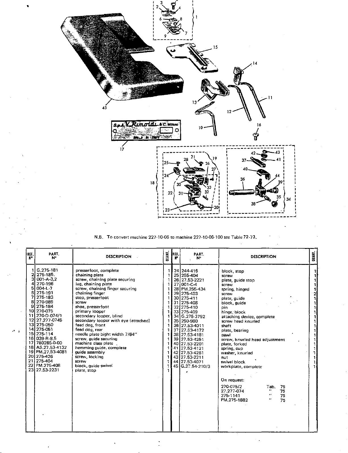
•
2~!4
6~8
~
11
:~I
I
~71
I 9 I
•-----------..1
14
11
45
16
i
17
REF.
N'
1
G.275-181
2
275-185.
001-A-3.2
3
4
270-196
5 004-L-7
s
275-191
7
275-183
8
270-989
275-184
9
10
270-075
270-D
11
12
27.277-07
13
275-050
14
275-051
15
275-114
16
039-R-8.5
17
780285-0-00
18
AS.27
19
PM.27.53-4081
20
275~26
21
275~04
22
PM.275-408
23
27.53-2231
PART.
N"
-07
4/1
45
.53-4132
N.B.
To
convert machine 227-10-06 to machine 227-10-06-100 see Table
DESCRIPTION
presserfoot, complete
chaining
screw, chaining plate securing
Jug,
screw, chaining
chaining
stop,
screw
shoe, presserfoot
primary
secondary
secondary
feed dog,
feed
needle
screw.
machine
hemming
guide
screw, locking
screw
block,
plate,
plate
chaining
finger
presserfoot
looper
looper,
looper
front
dog,
rear
plate
bight
guide
securing
class
guide,
assembly
guide
swivel
stop
plate
finger
with
plate
complete
blind
width
.
securing
eye
7/64"
(attached}
-'
z
RH.
<
~
N'
a
1 24
1
25
1
26
1
27 001-C-4
1 28 Prv1.255-434
1 29
1
30
1
31
1 32
1
33
1
34
1
35
1
36
1 37
1
38
1 39
1
40
1
41
42
1
43
1
1
44
1
45
1
PART.
N"
244-415
255-404
27.53-2221
275-403
275-411 plate,
275-408
275-410
275-409
G.275-3792
250-980
27.53-4011
27.53-4172
27.53-4181
27.53-4251
27.53-2201
27.53-4121
27.53-4261
27.53-2211
27.53-4071
G.2:'
.54-210/3
'
72-73.
block,
stop
screw
plate,
guide
screw
spring, hinged
screw
guide
block,
guide
pin
hinge,
block
attaching
screw head
shaft
plate,
pawl
screw,
plate,
spring,
washer,
nut
swivel
work
On
270-075/2
27.277-074
275-1141
P!'vl.275-1882
bearing
knurled
forked
cup
knurled
block
plate,
request:
device,
complete
DESCRIPTION
stop
complete
knurled
head
adjustment
Tab.
..
75
..
..
75
75
75
z
<
i5
1
1
1
1
1
2
1
1
1
1
1
1
1
1
1
1
1
1
,
1
1
1
Page 82

Z:U-11-Ul
1227-00-0
1l
--------~---.,
:
i
:
I~·
I I
._
I
~41
39
33~40
42~
___________
45
1
I~
44
1
_!
43
37
5
,-
EF.
•
270-075
1
2
270-0·074/1
3
27.277-0745
4
275-050
5
275-051
6
275-114
7
016-F-7
8
780300:0-00
9
AS.27.53-4132
PM.27
10
1 1
275-426
12
275-404
13
PM.275-408
14
27.53-2231
255-415
15
16
275-404
17
27.53-2221
001-C-4
18
PM.255-434
19
275-403
20
1
275-411
2
275-408
275-410
23
PART.
N'
.53-4081
;;
DESCRIPTION
primary
secondary loop·er,
secondary
feed
feed
needle
screw,
machine
hemming
guide assembly
screw, Jacking
screw 1
block,
plate,
block,
screw
plate,
screw
spring,
screw
plate,
block,
pin
dog,
dog,
plate
guide
guide
stop
stop
guide
hinged
guide
guide
looper
looper
front
rear
bight
set
class
guide,
swivel
stop
blind
with
width
plate
complete
eye (attached)
7/54"
~
=
a
On request:
270-075/2
27.277-074
275-1141
PM.275-1882
Tab.
"
..
"
75
05
75
75
PART.
N•
275-409
G.27.53-3792
250-980
27.53-4011
27.53-4172
27.53-4181
27.53-4251
27.53-2201
27.53-4121
27.53-4261
27.53-2211
27.53-4071
G.27.54-210/3
G.27.54-E-181
275-185
001-A-3,2
270-196
004-L-7 sr:rew, chaining finger securing
27
.54-E-191
275-183
270-989
275-184
hinge,
attaching
knurled
shaft
plate, bearing 1
pawl
screw,
plate,
spring,
washer,knuried
nut
swivel
workplate,
presserfoot,
chaining
screw,
lug,
~haining
chnining
stop,
presserfoot
screw 1
shoe,
presserfoot
N.B.
When
is
in
finger
complete
DESCRIPTION
block
device,
screw
head 1
knurled
forked
cup
black
complete
complete
plate
chaining
plate
finger 1
machine
converted
the
field,
27'.54-E-191 and
1
1
1
1
1
2
2
1
1
1
1
1
1
1
1
1
1
1
1
1
1
1
REF.
H'
24
25
26
27
28
29
30
31
32
33
34
35
36
37
38
39
40
41
42
43
44
45
complete
head
adjustment
plate
securing
227.10.06
to
227.11.01
supply
presserfoot
chaining
not
G.27
is
.54-E-181.
!;i
~
=
a
1
1
1
1
1
1
1
1
1
1.
1
1
1
1
1
1
1
1
•
Page 83

.------------.
1 I
I
1"--
....-141
:11~~13!
I
I
11~~
:
!__
___________
~
.n
15
16:
10
•
..
REF.
N'
8
9
10
11
12 001-A-3,2
13
14
15
16
17
PART.
1
001·0·7
2
270-075
3
270·0·07411
4
27.277·0745
5
275·050
6
275·051
7
275·114
780286·0·00
PM.27.53-210/3
G.275·181
275-185
270·196
004·L·7
275·191
275-183
270·989
N"
S.p.A.
..
~,,..;~~:.-.9~·
al
DESCRIPTION
screw, guide securing
primary
looper
secondary looper, blind
secondary looper
feed dog,
feed dog, rear
needle plate bight width
machine class plate
workplate,
presserfoot,
chaining plate
screw, chaining plate securing
lug, chaining plate
screw, chaining finger securing
chaining finger
stop,. presserfoot
screw
front
complete
complete
with
.
eye
7/64"
(attached)
a
c.
lliMM~
;;
~
=
0
1 18
1 19
1
1
1 22
1 23
1
1 25
1
1 27
1 28
1
1
1
1
1
1
IEF.
II'
20
21
24
26
29
30
31
32
33
PART.
N"
275·184
AS.275-413
275-426
PM.275-4~7
PM.275-408
275-403
275·411
275-408
275-410
275-409
275-425
275-404
PM.275·407
275-407
275-415
275·416
•
;;
DESCRIPTION
shoe, presserfoot 1
hemming
screw 1
support arm
block, guide assembly
screw 1
plate, guide
block, guide
pin
hinge, block
screw, knurled head
screw
pressure blade and spring assembly
blade
slide guide
spring 1
On
270-075/2
27.277-074
275-1141
PM.27~·1882
request:
guide,
complete
adjustment
Tab.
..
..
75
75
75
75
~
i5
1
1
1
1
1
1
1
1
1
1
1
1
-
.
' I
Page 84

1227-0P-01 I
r----------------,
,
' I
' I
I I
I
14---..,___,...-
~IS
II
1
!
i .
i
I
I
~13
~;S-12:
~I
16
\'0
I
~----------------J
5
~------'
-
.,...
7
4
2
,.
3
El.
M•
i
i
i :
! i
16
:7
)8
PART.
N'
270-{)75
~
27 .01-P9-1 13/1 knife, lower
27.277-0745 secondary looper
278-{)52
278-114
780225-0-00
279-{)50
279-{)51
primary
feed dog, chaining
needle plate bight width
machine class plate
feed
dog,
feed dog, rear
DESCRIPTION
looper
front
5/64"
'
;!
REF.
~
=
••
0
1 9 279-112 knife, uoper
1
10
1 1 1
1 12
13 278-191
1
14 270-196
1
1
15
1 16 278-184 shoe, presserfoot
PART.
N'
G.278-181
270-989
270-183
004-L-7 screw, chaining finger securing
presserfoot,
screw
stop, presserfoot
chaining finger
lug, chaining finger
On request:
complete
DESCRIPTION
278-114/1
Tab.
i.
..
76
Page 85

r----------------
r 20
1
1
!
19~16
l
~8
1
15
:
I~
I I
I
21
,'.
--
- :
17:
L-----------------
5
3
II
-·------r
4
1
" I
<I
I
I
I
I
I
I
I
I
'.
I
_,
REf.
••
1 001-D-7 screw, guide securing
2
3
4
5
6
7
8
9 279-051
10
1 1 G.272-G-401
PART.
N"
270-075
27.01-P9-113/1
27.277-0745
278-052
278-114
780452-0-00
279-050
279-112
primary looper
knife, lower
secondary
feed dog, chainirlg
needle plate bight width
machine class plate
feed dog,
feed dog, rear
knife, upper
guide, lace attaching
looper
front
DESCRIPTION
5/64"
-
;;
~
=
c
IEf.
••
1
12
13
1
1
14
1
15
16
1
17
1
1
18
1
19
20
1
21
1
1
PART.
N"
004·A-2,5
PM.272-G-417
PM.27 .03-P-402
G.278-181
270-989
270-183
278-191
270-196
004-L-7
278-184
7
DESCRIPTION
screw
bearing
arm
guide
presserfoot, complete
screw,
stop
stop, presserfoot
chaining
lug, chaining
screw, chaining finger securing
shoe, presserfoot
securing
finger
plate
5
=
c
1
1
1
1
1
.
1
1
1
1
1
Page 86

227-30-04
{227-00-011
~----------------------
!
17
19-:
I
18
20
: ;
l-j----
J~
15\!/
!11
4
13
:
~r-12
~--------------------------------------1
I I
I I
I I
I I
I
I
I
I
I
I
I
I
I
I I
I I
I I
L---~----··-··-----------------------·++---~
47
34
32
~
~----------------------1
:
I
I
I
I
5
'
I
I
I
I
I
I
~-------
40
---
---
---
---
--,
............
I
I
I
I
I
I
--
--·
-----------
....
_..
...
,-----------
I I o
I I I
---··---·---~~~~~~~:~---''•
u\
I
I
.
_____
::::::::::::::::::::::::::::::::::::_:
27
'
'
I
I
I
I
~
21
I
I
I
I
I
I
I
I
I
I
I
I
,.
'·
i :
i
I
REF.
H'
10
11
12
13
14
15
16
17
18
19
20
21
22
23
24
PART.
N'
1 TS.20 X
2
270·075
3 27.01-?9-113/1
4
27.277-0745
5
278-052
6
278-114
7
780453-0-00
8
279-050
9 279-051 feed dog, rear
279-112
G.278-MG·1811 presserfoot, complete
054-D-4
278-MG-1841
278·191
270-196
004·L·7
PM.272-NH-199
270-701 snap ring
272-NG-199
272-NG-197
AS.272-MG-937
272-MG-4333
605-980
272-MG-937
30
screws
primary
knife, lower
secondary looper
feed dog, chaining
needle plate bight
machine
feed dog,
knife,
nut
shoe, presserfoot
chaining finger
lug, chaining plate
screw, chaining plate securing
roller,
shaft
roller
metering device
bar
lock-screw
bracket
looper
class
front
upper
with
DESCRIPTION
width
plate
shaft
for
5"
5/64"
lace
!i
~
=
a
REF.
"'
25
2
1
25
27
1
1
28
1
29
1
30
1
31
32
1
33
1
1
34
1
35
1
35
1
37
1
38
1
39
1
40
1
41
42
1
1
43
44
1
45
1
1
46
2
47
1
48
PART.
N•
G.272·MG-4192
PM.502-E-4364 wing nut-with shank 2
PM.272·MG-4302 frame-plate,
272·MG·4212
038-C-7
272-MG-4242
PM.272-MG-4342
G.272-MG-4412
039-C,10.5
272-MG-4332
272-MG-4412
160-232/4
160-030
1032
a
160-032
G.635-937
01141
001-G-12
605·143
605-723
605·937
605-980
505-144
feed control, lower
rod
screw 2
block, coupling
plate, width adjustment 1
feed control, upper 1
screw 2
block, mounting
hinge, drag 2
spring 2
pin 2
bushing
screw, adjustment knurled head 2
reel carrier, complete 1
base
screw
upright
sleeve, tapered
bracket
screw, set 5
pin
On
request:
DESCRIPTION
with
rod 1
.
AS.272-MG-9371
Tab.
77
z
~
=
a
1
1
1
2
2
1
1
1
2
1
2
•
Page 87

•
r;~··i~n-~~;\\
: .
I -
:~14
I
I
19
17
13
12
I
I
6
L------------1
8
3-.
·'
REF.
H'
1
028·8·8
2
270·075
3
27.277-0745
4
279-050
279-051
5
6
279·099
7
279·112
279-113/1
8
279-114
9
10
780226-0-00
PART.
N"
screw,
chaining
primary
secondary
feed
feed dog, rear
knife
knife,
knife,
needle
machine
looper
looper
dog,front
holder,
upper
lower
plate
class
DESCRIPTION
plate
upper
bight
width
plate
securing
5/64"
,..,
z
<
;;:
1
1
1
1
1
1
1
1
1
1
llEf.
H'
11
279-987
12
G.279·181
13
279-191
14
PM.279-183.
15
275-185
16
001·A·3,2
17
270-196
004-L-7
18
279-184
19
20
G.279-216/2
PART.
N"
10
DESCRIPTION
screw, upper knife mounting
presserfoot, complete
chaining
stop,
chaining
screw, chaining
lug,
screw, chaining
shoe, presserfaot
front
finger
presserfoot
plate
chaining
coverplate,
plate
plate
finger
securing
securing
complete
On request:
270-075/2
27.277-074
Tab.
..
75
75
i
=
0
1
1
1
.
1
1 I
1 I
1
1
1
1
Page 88

~~J·..Ju·u;,;
1227-00-011
c----2c-------:
: \
:
~23
I
20,/\.~.
I
~~fftfl-19
l
~~._l8
I 24
______________
I
~
i-n
·-
I
~
17
I
J
25
12
13
s
IF.
H'
8
10 279-051
11
12
13
PART.
,..
1
PM
.27 .03-P-402
2 PM.272-G-417
3 004-A-2,5
4 G.272-G-401
5 001-D-7
6 028-B-8
7
270-075
27.277-0745
9
279-050
279-099
279-112
279-113/1
DESCRIPTION
guide
arm, bearing
screw
guide, lace attaching
screw, guide securing
screw, chaining plate securing
primary looper
secondary looper
feed dog,
feed dog, rear
knife
knife, upper
knife, lower
front
holder, upper
15
;i
~
=
0
1
1 15
1
1 17
1 18
1 19
1
1
1
1
1
1 25
1
REF:
H'
14
16
20
21
22
23
24
PART,
N•
279-114
780454·0·00
279-987
G.279·181
2:'9·191 chaining finger
PM.279-183 stop plate
275·185
001-A-3,2
270·196
004-L·7
279-184
G.279-216/2
DESCRIPTION
needle plate bight width
machine
screw,upper knife mounting
presserfoot, complete
chaining plate
screw, chaining plate securing
lug, chaining plate
screw
shoe,
from
class
plate
presserfoot
coverplate, complete
5/64"
;;
~
0
=
1
1
1
1
1
1
1
1
1
1
1
1
•
Page 89

·--·
.......
-
...
•
12
8
"
REF.
••
028-B-8
1
2
270-075
3
27.277-0745
279-050
4
5 270-051
Q
279-099
7
279-112
8
279-113/1
9
279-114
10
780227-0-00
PART.
N"
DESCRIPTION
screw, chaining plate securing
primary looper
secondary looper
feed dog,
feed dog, rear
knife holder, upper
knife, upper
knife, lowP
needle
'
machine class plate
front
..
pl<~te
bight
-
width
3/.32"
;;
~
=
0
1 11
1
1
1
1
1
1
1
1
1
REF.
••
12
13
14
15
16
17
18
19
20
PART.
N"
279-987
G.279-216/2
279-184
G.2791-1811
27.91-1911
PM.279-183 plate, presserfoot
275-185
001-A-3,2 screw, chaining plate securing 1
270-196
004-L-7 screw 1
screw, upper knife
front coverplate,
shoe, presserfoot
presserfoot,
chaining finger 1
chaining plate
lug, chaining plate
DESCRIPTION
mounting
complete
complete
stop
;;
~
=
0
I
1
1
1
1
-
1
1
-
Page 90

227-29-08
1227-0Q-01 I
r-----------,
I 7 8 0 ./110 I
~~~~....-
I
I
..
·
i
~7!-:~
15~
L-----------
...........-
9
I
)6
I
2
,.
279-)14
PART.
N•
REF.
••
1 279-112
2 279-113/1
3
4 780437-Q.OO
5 279-184
6 G27.91 E·191
DESCRIPTION
knife, upper
knife, lower
needle plate bight
machine class plate
shoe, presserfOot
presserfoot, complete
width
3/32"
~
REF.
~
N'
=
~
1
7 275-185
1
8
1
9
1
10 004 L-7
1
11
1
12
PART.
N"
001 A-3,2
27(). 196
27.91·191 1
P.M27.91 E-183
DESCRIPTION
chaining plate
screw, chaining plate securing
lug, chaining· plate
screw
chaining finger
plat.e, with
N.B.
tube
When
machine 227.00.01
into
227.29,09
the
pJate
complete
E-181.
chaining
not
G27.91
in the field, supply
PM.27.91
presserfoot
is
convert~
E·183
and
z
""
~
=
1
1
1
1
1
1
.
Page 91
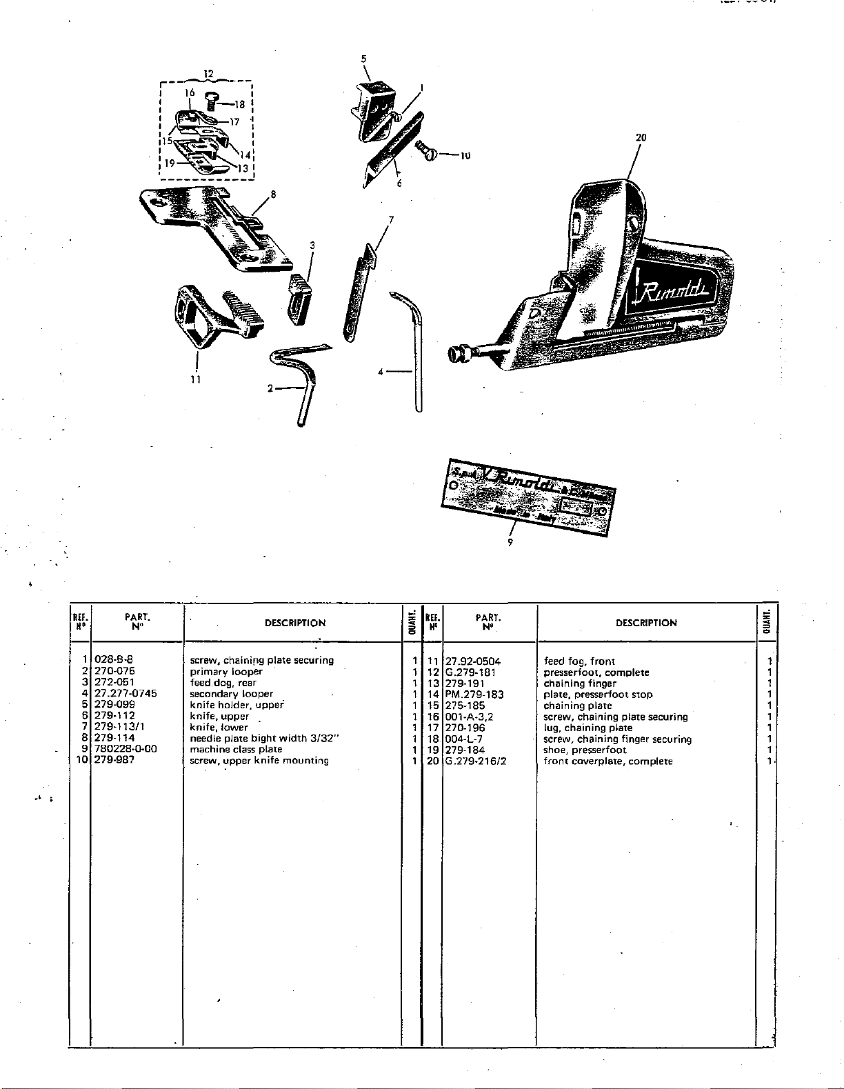
19
12
16
'i I
·~
17
--.
141
13
·I
I
I
J
r--
I
I I
•~a•
I
:1~~:
I
I
I -
.
___________
5
·--
_,
'REf.
••
1 028-B-8
270-075
2
3 272-051
27.277-0745
4
279-099
5
6
279-112
7 279-11311
279-114
8
780228-0-00
9
10
279-987
PART.
N"
screw, chainifl9
primary looper
feed. dog, rear
secondary
knife holder,
knife, upper
knife, lower
needle plate
machine class
screw, upper
looper
bight
knife
'
DESCRIPTION
plate
securing
uppei
width
plate
mounting
3/32"
-'
~
REf.
~
=
c
••
1
11
1
12
1
13
1 14 PM.279-183 plate, presserfoot stop 1
1 15 275-185 chaining
1
16
1 17 270-196
1 18
1 19
1
20 G .279-216/2
PART.
N"
27.92-0504
G.279-181 presserfoot, complete 1
279-191 chaining
001-A-3,2
004-L-7 screw, chaining finger securing
279-184
feed fog,
screw, chaining plate securing
lug, chaining
shoe,
presserfoot
front coverplate, complete
DESCRIPTION
front
finger
plate
plate
-'
~
~
=
c
1
1
1
1
1
1
1
1·
Page 92

:--~--,7-----;;;~;-1
:16 II
I
I
1.:1
I
I
20
·-------------
18~·
13
15
--·
12
\.l.!t-Uu-UII
5
7
I .
·-~...
~,_..
'
'
3-
t1
Qt
I
10
REF.
N'
028-B-8
1
2
270-075
3
27.277-0745
4
279-050
5
279-051
6
279-099
7 279-11311
8
780229-0-00
9
279-987
10
27.94-1012
27.94-1122
11
PART.
N'
DESCRIPTION
screw, chaining
primary
secondary
feed
dog,
feed
dog,
knife
holder
knife,
lower
machine class plate
screw,
knife
bushing,
knife,
upper
looper
looper
front
rear
mounting
lower
plate
knife
securing
holder
.
:;;;
REF.
~
N'
e 0
1
12
1
13
1
14
1
15
1
16
1 17
1
18
1
19
1
20
1 21
1
PART.
N"
27.94-1142
G.27.94-1812
27.94-1912
27.94-1832
275-185
001-A-3,2
270-196
004-L-7
279-184
G.27.94-2152/2
DESCRIPTION
needle
plate
bight
width
1/8"
to
presserfoot,
chaining finger
plate, presserfoot.stop
chaining.
screw
lug,
screw 1
shoe, presserfoot 1
front
On request:
270-075/2
27.277-074
plate
-
chaining
coverplate,
complete
plate
complete
9/64"
l'ab.•
" 75
.
75
~
= =
1
1
1
1
1
1
1
1
Page 93

L.L.J·,jU·UQ
1227-00-011
.--------------·
I
I I
I , 22
·;20
~~r
I
:
,
______________
21
Q 1
1!1-23
~
.
..-
~i--\8
24
~
.1'9
I
17
I
J.
25
,.
6
REF.
••
1
279-113/1
2
001-D-7
3
028-B-8
4
270-075
5
272-051
6
27.277-0745
7
279-099
8
279-112
9
279-114
1 i
780455-0-00
11
279-987
12
27.94-0504
13
G.272-G-401
r
--------
-
t·
--16
I I
I I
13
~
1 I
I I
I I
I I
'-'---------/-
PART.
N•
-
___
..
___ ~ ...
-.---------1
2
knife, lower
screw, guide securing
screw, chaining plate securing
primary looper
feed dog, rear
secondary looper
knife holder, upper
knife, upper
needle plate bight width
machine
screw, upper knife mounting
feed dog, front
~uide,
class
lace
attaching
--.,
:
j
DESCRIPTION
3/32"
plate
10
;i
~
=
a
1
1
1
1
1
1
1
1 21
1
1
1
1
1
REF.
••
14
15
16
17
18
19
20
22
23
24
25
PART.
N'
004-A-2,5
PM.272-G-417
PM.27
.03-P-402
G.279-181
279-191
PM.279-183
275-185
001-A-3,2
270-196
004-L-7 screw
279-184
G.279-216/2
z
DESCRIPTION
screw 1
arm, bearing 1
guide 1
presserfoot, complete
chaining finger 1
plate, presserfoot stop
chaining plate
screw 1
lug, chaining plate
shoe,
presserfoot 1
front coverplate, complete 1
c
=
a
1
1
1
1
1
.
Page 94

~.c.1·vv-
1227-00-011
1 1
.-----
I I
:
--------~
!.--12
13
:
s.,.A.
o.·
,
,'
i
"~
: \ - I
I
1
11
l·
j
~-------------·
~,-
d.J)-17
~·
...............
I
l\
I
I
I
I
I
L-------·--:~
3
I
,
--
,--_-
.....
,
,..
,..,.;
--
...............
-=&c..,_
CJo
--
,/
..
==~--
--------------1
,.
I
I
I
I
If.
N'
1
4 27.21-1141.
8 G.27.21-C2-009/4
9 G.27.21-CC-181
10
PART.
N"
270-0751
3
780211-0-00
5 27.21-C-050
6
270-074
7 279-051
27.21-CC-191
DESCRIPTION
primary looper
machine
needle plate bight width
feed dog, front
secondary looper with
,
feed dog, rear
main shaft and connecting
presserfoot, complete
chaining finger
class
plate
3/64"
eye
rods
to
1/16"
;;
KEF.
~
N'
=
~
1
11
12
1 13 004·L-7 screw, chaining finger securing
1 14
1
15
1
16
1 17 27 .21-C2-617
1
1
1
PART.
N•
•
270-183
270-196
270-989
27.21-C-184
G.27.21·C2-067/3
--
DESCRIPTION
stop, presserfoot
lug, chaining plate
screw, stop securing
shoe, presserfoot
drive assembly, secondary looper
rocker
On request:
27-2-050 Tab.
272-051
272-092
G.272-181
-
-
..
..
75
75
75
76
..
;;
~
=
~
1
1
1
1
1
1
1
-
I
Page 95

~--------------,
1
: . I
:
l 2
:
I
I
I
---.------------1
r-:13
~12
~-
~10~
15
't.J4
.-
. 1
11
1
il
1
9
17
~\
---.
·6
dv-
;--------
I '
I I
I '
I I
I I
L----------------------------J
i
i·
•
-·
REF.
••
11
PART.
N'
270·0751
~
PM.27.91-E.-183
780436
~
i
E
~
·0-00
27.21-E
27.21
270-074
279-051 feed
G2721C2-009/4
G.27.21·E·181
27.21-E-191
114
-C-050 feed dog,
primary
plate,
machine
needle
secondary
main
presserfoot,
looper
with
tube
class
plate
front
looper,
dog,
rear
shaft
and
;haining finger
DESCRIPTION
plate
bight
width
wi_th
connecting
complete
3/64"
eye
rod
to
1/16"
assembly
~
REF.
~
••
~
= =
1 1
1
1
12
1
13
1
14
1
15
1
16
17
1
1
1
1
PART.
N"
27.21-E-183
270·196
004-L-7
270-989
27.21-E-184
G2721
C2-067/3
27.21·C2·617
DESCRIPTION
stop,
presserfoot
lug, chaining
screw, chaining finger
screw,
shoe,
drive assembly,
rocker
plate
presserfoot
.presserfoot 1
securing
stop
mounting
secondary
looper
J
'.
z
~
~
1
1
1
1
1
1
Page 96

1227-00-011
"-
N'
2 003-M-7
3
4
5
6
7
8
.g
10
11 PM.27 .21-C-050
12
13
14
15
16
17
18
19
20
21
PART.
N"
1 001-D-7
270.075
270-263
270·270
270-274
780209·0-00
27.21-C-220
270-074
128·110
PM.27.21-C·051
PM.27.21·C·114/
G.27.21-C-181/2
27.21-C-191/2
270-183
278·184-C2
270-196
004-L-7
270-989
AS.27.21-C-700
1----b
N.B.
screw,
guide
screw, cap
primary
thread
thread
thread
machine
guard, feed
secondary
shield,
feed
feed dog, rear
needle
presserfoot,
chaining
chaining
shoe,
lug,
screw
screw,
tensioning
looper
guide,needle
take-up,
take-up,
class
dog
looper·
upper
dog,
front
plate
finger
plate
presserfoot
chaining
presserfoot
disc
To
convert a type
DESCRIPTION
mounting·
secondary
needle
plate
knife
holder
bight
width
complete
plate
stop
and
pulley
looper
3/64"
mounting
assembly
.9
227·00-09
to
1/16"
41
'
I
I
L--------~---~--------·--------1
r------
1
_________________
into a 227-0Q-09-100
REf.
s
H'
=
a
1
22
3
23
24
1
1
25
1
26
27
1
1
28
1
29
30
1
,1
31
1
32
1
33
1
34
1
·35
1
36
1
37
1
38
1
39
40
1
1
41
1
42
',~40
PART.
N"
27.21-C-983
001-G-10
G.27.21-C'700
27.21-C-702
057-R-5
PM.27.21-C-708
27.21-C-708250-031 tensioning disc
27.21-C-709
240-035
27.21-C-232
3710
G.27.21-C-703
G.27.21-C·704
3707
270-701
PM.27.21-C-704
27.21-C2-617
G.27
.21·C2-067/3
G.27
.21·C2-009/4
"'-...
see
illustration
',
',
I
I
I
I
J
I
screw
screw
tension disc assembly
angle
nut
shaft
shaft
shim
washer,
spring
knurled
plate
pulley
shaft
snap
pulley
rocker
drive
main
10
~
r:JFV
72-73
bar
with
discs
cup
knob
with
bushing
shaft
ring
assembly,
shaft
and
DESCRIPTION
secondary
connecting
looper
rod
assembly
•
''
;:
~
~
a
1
1
1
1
2
1
1
6
1
1
1
1-
1
1
1
1
1
1
1
1
On
request:
PM.27.21-C"114
G.27.21-C-181
G.27.21-C-181/1
Tab.
"
"
7'5
75
75
I
.
·-
Page 97

:----1-----i~:-l
I • 1
w
..
'~
-
~1
~
~,~~-
c~"-
ts/
I
1/
...
,'1
VII
'~-
16 -
1
12
·..
:
L--------~~--~--J
~
~'
2-
:
7
-----
I I
---------,-
L----------------J
1
I
I
I
I
I
I
I
I
I
I
·'
N.B.
To
convert machine 227-0D-10 into machine 227-00-10-100 see illustrations 72/73
REF.
••
1
2
3 27.21-C2-617 rocker
4 78021
5
6
7 27.221-C-074/1
8
9 279-051 feed dog, rear 1
PART.
N'
003-M-7 screw, cap 1
270-075
0-0·00
27.21-1143
27
.21-C-050 feed dog,
128-110
primary
machine class plate
needle-plate bight width
secondary looper, blind 1 16 27.21-C-184 shoe, presserfoot
shield, upper knife holder
looper
front
DESCRIPTION
3/64"
to
1/16"
~
REF.
~
=
••
a
10 G.27.21-CC-181 presserfoot, complete
1
11
1
12
1 13
1
14
1 15
1 17
18
PART.
No
27.21-CC-191 chaining finger
270-183
270-196
004-L-7 screw
270-989
G.27.21-C2-009/4
G.27.21-C2-067/3
chaining plate
lug, chaining plate
screw
main shaft and connecting rod assembly
drive assembly, secondary looper
DESCRIPTION
=
a
"'
1
1
1
1
1
1
1
1
1
'
-
Page 98

227-28-07
1227-00-011
~----
----,
I
~
I
14-tJ
I \
I
11~
~
.........
-,
I
I
~13
9
~ISJ
~
I~
.I
·~-,.--
I
I
I~~~
~.-I
~
~
:-:..~21
·-----------
\
\
\
\
17
l:l..IJI
\
\
'
16
__
...
-----
--·
';
11
___________________
11
tL.
_.
...
----------,
.........
,.
...
,
....
~
,
~
$3
""
I
I
I
)
,-
IF.
••
1
2
3
4 PM.272-1S-114
5
6 PM.27.21-C-050
7 PM.27.21-C-051
8
9 G.27.21-C-181/1
10
11
12
PART.
N"
27.21-C-220
270-0751
27.21-C2-617
780416-0-00
270-074
001-0-7
27.21-C-183/1 chaining plate
27.21-C-184/1 shoe, presserfoot
guard, feed dog
primary
rocker
needle plate
machine
feed ·dog,
feed dog, rear
secondary looper,
presserfoot, complete
screw
looper
class
front
DESCRIPTION
plate
.:
REf.
~
=
••
0
13
1
14
1
1 15 272-C-191/1
16
I
1
17
18
1
1
19
1
1
1
22
. 1
23
1
PART.
270-196
004-L-8
270-183
270989
272-8-052
128-110
I
G.27.21-C2-009/4
G.27.21-C2-067/3
""
5
DESCRIPTION-
lug, chaining plate 1
screw
chaining finger
stop, presserfoot 1
screw
feed dog, chaining
shield, upper
main shaft
drive assembly, secondary looper 1
I.
knif~
holder 1
with
connecting
rod
assembly
i
=
0
1
1
1
1
1
Page 99

~----------
I Q I
I
:1~
i
~18
:1~:
'-----------
g-20
"i
l
16
13
~~"
27/L'
·~
-·
Rlf.
••
10
11
12
13
14
PART.
N'
1 272-BK-987 screw,
270-0751 primary looper
2
27.22-0504
~
27.22-0514
27.22-0524
5
6
270-074
7
27.22-0994/1
780417-0-00
8
9
27.22-1034
27.22-1074
27.22-1094
27.22-1114
27.22-1124
27.22-1134/1
feed dog,
feed dog, rear
feed dog, chaining
secondary looper, blind
knife
machine class plate
lug,
needle guard, front
needle guard, rear
shield, upper knife
knife, upper
knife, lower
DESCRIPTION
Jug
securing
front
holder, upper
upper
knife
stop
si
REF,
•
=
••
0
15
27.22-1144/1
1
1 16
G.27.22·1814/1
1 17
27.22-1844/1
1 18
27.22-1914.
1 19
270-196
1
20
004-L-7
1
21 G .27.22-2164/2
1
22
27.21-C2-617
1
23
G.27.21-C2-067/3
24
1
G.27.21-C2-009/4
1
1
1 27
27.22-9874
1
28
PART.
N'
DESCRIPTION
needle plate bight width
presserfoot,
shoe, presserfoot
chaining finger
lug, chaining
screw
front
rocker
drive assembly, secondary looper
'main shaft with
screw, upper knife holder mounting
On request:
G.27 .22-2624/1 Tab.
27.221-C-074/1
complete
plate
cover plate, complete
connecting
3/64"
to
rods assembly
..
1/16"
76
76
.
i
=
0
1
1
1
1
1
1
1
1
1
1
1
Page 100
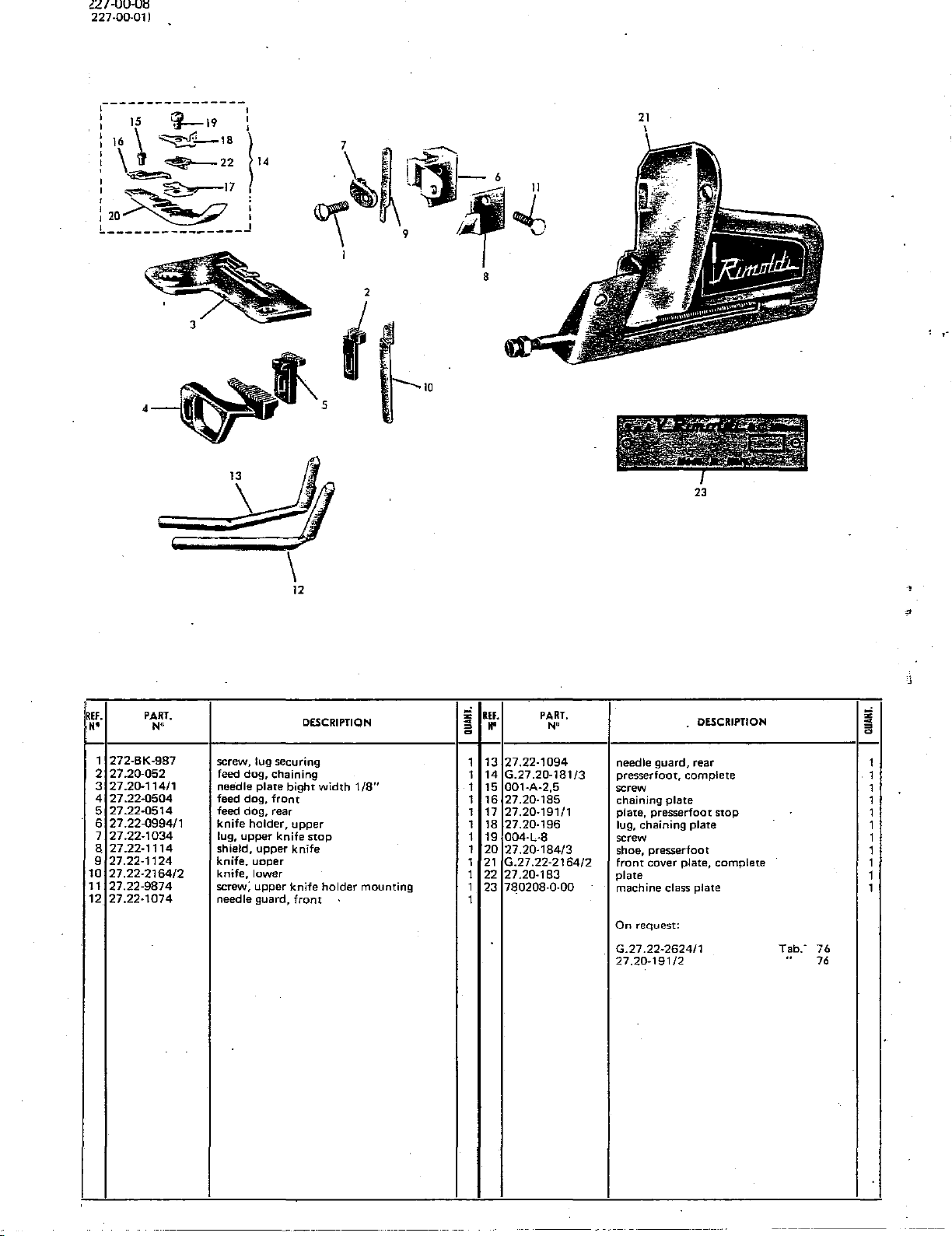
I:U·UU·U~
227-00-01)
~---------------1
:
15
i
16
\
I \
\l
·~
:
~~171
~~
li---19
~'--18
~
22
:
l
14
.
12o~l
L---------------J
\ . 9
2
---.10
"'
v
8
·~~"·
\
'
u
~\111
\
12
21
23
REI.
••
1
272-BK-987
2
27.20-052
3
27.20-114/1
4
27.22-0504
5
27.22-0514
6
27.22-0994/1
7
27.22-1034
a
27.22-1114
9
27.22-1124
10
27.22-2164/2
11
27.22-9874
12
27.22-1074
PART.
N"
DESCRIPTION
screw, lug securing
feed dog, chaining
needle plate bight width
feed dog,
feed dog, rear
knife holder, upper
lug,
shield,
knife. uoper
knife,
screw;
needle guard,
upper
upper
lower
upper
front
knife
knife
stop
knife
holder
front
1/8"
mounting
;i
~
=
~
1
1
1
1
1 17
1 18
1
1
1 21
1
1
1
REF.
..
13
14
15
16
19
20
22
23
PART.
N"
27.22-1094
G.27.20-181/3
001-A-2,5
27.20-185
27.20-191/1
27.20·196
004-L-8
27.20-184/3
G.27.22·2164/2
27.20-183
780208-0-00
!iii
76
76
~
=
~
I 1
. DESCRIPTION
needle guard, rear 1
presserfoot,
screw 1
chaining
plate, presserfoot
lug, chaining plate
screw 1
shoe, presserfoot
front
plate
machine
On
request:
G.27.22-2624/1
27.20·191/2
complete
plate
cover plate, complete
class plate
stop
Tab.·
"
1
1
1
1
1
1
1
 Loading...