

Page 1

Rimoldi®
INSTRUCTIONS HANDBOOK
LIBRO DE INSTRUCCIONES
LIVRET D'INSTRUCTIONS
GEBRAUCHSANWEISUNGEN
Feed-off-the-arm
n.652
Page 2
AVVERTENZE
SICUREZZA
II
motore di azionamento e le eventuali apparecchiature montate sulla macchina DEVONO
ESSERE DISINSERITI
procedere all'infilatura della macchina o accedere all'interno di essa
sostituire gli organi di cucitura
intraprendere lavori
lasciare, anche momentaneamente,
prodotti Rimoldi ai quali fa riferimento il presente libretto istruzioni, sono completi di tutte le
I
protezioni antinfortunistiche previste dalle leggi vigenti. ·
Anche i
come tali devono
Pertanto i dispositivi di sicurezza montati, non devono essere rimossi se non per operazioni
manutenzione e poi rimontati. Tali operazioni sono
rete
La
dall'inosservanza, anche di una sola
GARANZIA
I
prodotti Rimoldi sono sottoposti a scrupolosi controlli e a rigorosi collaudi che permettono di
garantime
il quale tali prodotti vengono usati e dalla precisa manutenzione che sara destinate
Attenendosi sempre
garanzia di
Ia
La
di impiego di ricambi non originali.
silenzi~tori
di
alimentazione, agenda sull'apposito interruttore.
Rimoldi S.r.l. decline ogni responsabililil, sia civile che penale, per gli infortuni derivanti
Ia
durata e l'efficienza,
qualita dei particolari montati in origine, si ottiene
funzionalita e
Rimoldi S.r.l. decline ogni responsabilita di malfunzionamento o danno ai propri prodotti nel
il
DALLA RETE Dl ALIMENTAZIONE PRIMA Dl:
di
manutenzione sulla macchina
il posto di Iavere
montati nell'impianto pneumatico sono considerati dispositive di sicurezza e
essere puliti se mal funzionanti,
delle succitate regale basilari di sicurezza.
rna
queste performances dipendono notevolmente dal modo con
all'uso di Ricambi Originali Rimoldi marcati Rim, gli unici che offrono identica
valore commerciale dei prodotti Rimoldi. ·
rna
non esclusi.
da
eseguirsi sempre a motoredisinserito dalla
ad
essi.
Ia
sicurezza di mantenere
neltempo
casc1
di
.·:
•
La
Rimoldi
S.r.J.
si
riserva
il
diritto
di
modificare o
variare,
i dati e /e informazioni riportati nel presente manuale .
per
motivi
di
ordine tecnico o commercia/EI
Page 3
INTRODUZION!;
PRESENTAZIONE
CARA
TTERISTICHE
SOMMAAJO
NORME
IMPIANTO
GENERALI
ELETTRICO
SCHEMIDICOLLEGAMENTO
JNSTALLAZIONE
Montaggio piastra su bancale a colonna
Montaggio piastra su bancale regolabile
Montaggio motore
Montaggio ammortizzatori
Montaggio testa
Collegamento
Collegamento alza piedino .
RIFORNIMENTO
SOSTITUZIONE E FASATURA
Note sulla fasatura albero superiore e inferiore
Aghi
Piedino
Placca ago
Colle
IIi
Crochet inferiore
Crochei copertura superiore
- forato
testa·motore
OLIO
ORGAN!
• cieco
Salva aghi • spingi aghi
Griffe
OJ
CUCJTURA
REGOLAZIONE
REGOLAZIONE
Regolazione tensione
Regolazione e controllo tirata
Jnfilatura e regolazione filo crochet inferiore
lnfilatura e regolazione
TRASPORTO
LUNGHEZZA
fiJi
fili crochet di copert!Jra
DIFFERENZIALE
PUNTO
aghi
-TENSION!
fiJi
aghi
FILl
MANUTENZIONE
ANOMALIE
DOVUTE A IMPROPRIA
CONDUZIONE
DELLA
MACCHJNA
·.·:.
Page 4
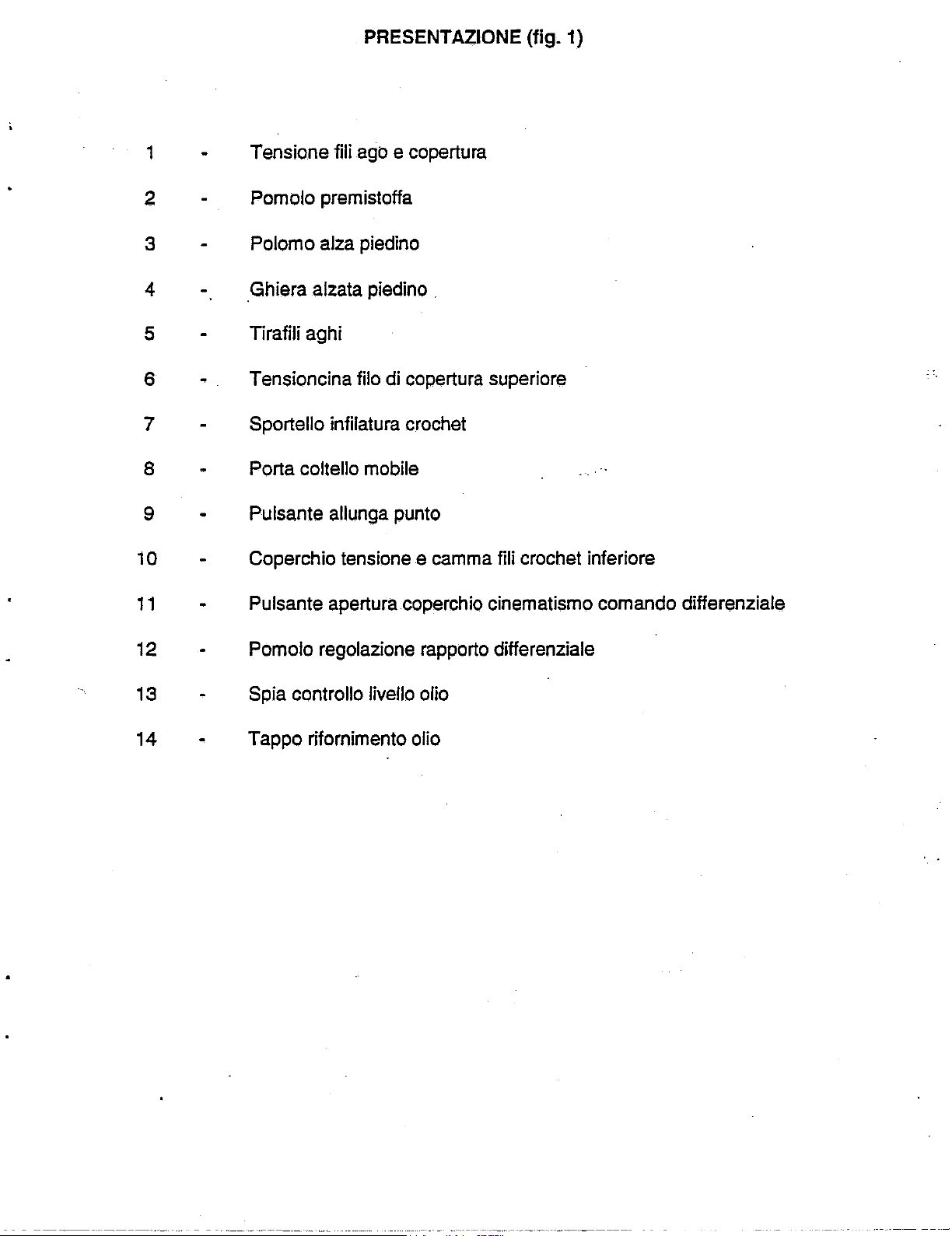
PRESENTAZIONE (fig. 1)
1 Tensione fili
2 Pomolo premistoffa
3
4 Ghiera alzata
5 Tirafili aghi
6 Tensioncina
7 Sportello infilatura
8 Porta coltello
9 Pulsante
10 Coperchio
11
Polomo
Pulsante apertura
ago e copertura
alza
piedino
piedino
filo
di
mobile
allunga
tensione e camma
.
copertura
crochet
punto
coperchio
superiore
fili crochet inferiore
cinematismo comando differenziale
12
13
14 Tappe rifornimento olio
Pomolo
Spia
regolazione
controllo livello
rapporto
olio
differenziale
Page 5
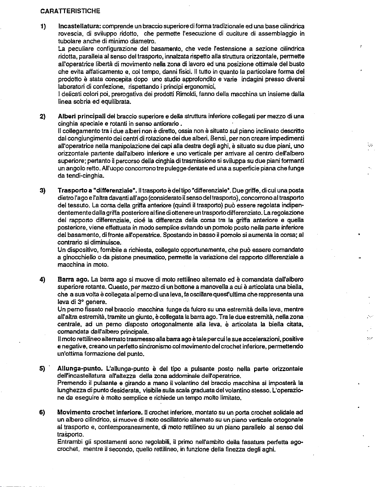
CARA
TTERISTICHE
1)
lncastellatura:
rovescia, di sviluppo ridotto, che permette l'esecuzione di cuciture di assemblaggio in
tubolare anche di minimo diametro.
La
peculiare configurazione del basamento, che vede l'estensione a sezione cilindrica
ridotta, parallela al sense del trasporto, innalzata rispetto alia struttura orizzontale, permette
all'operatrice
che evita atfaticamento
prodotto
laboratori di confezione, rispettando i principi ergonomici,
I delicati colori poi, prerogative dei prodotti Rimoldi, fanno della macchina un insieme dalla
linea sobria ed equilibrate.
2)
Alberi
cinghia speciale e rotanti in senso antiorario .
II
dal congiungimento dei centri di rotazione dei due alberi. Bensi, per non creare impedimenti
all'operatrice nella manipolazione dei capi alia destra degli aghi,
orizzontale partente dall'albero inferiore e uno verticale per arrivare al centro dell'albero
superiore; pertanto il percorso della cinghia di trasmissione si sviluppa su due piani formanti
un angolo retto. All'uopo concorrono
da
principali
collegamento tra i due alberi non e diretto, ossia non e situate sui piano inclinato descritto
tendi-cinghia.
comprende un braccio superiorediforma tradizionale ed una base cilindrica
Iiberti! di movimento nella zona di lavoro
e,
col tempo, danni fisici.
e stata concepita dopo uno studio approfondito e varie indagini presso diversi
del braccio superiore e della struttura inferiore collegati
Ire pulegge dentate ed una a superficie piana che lunge
ed
una posizione ottimale del busto
II
tutto in quanto
Ia
particolare forma del
per
e situate su due piani, uno
mezzo di una
Trasporto a "differenziale"
3)
I'
dietro
del tessuto. La corsa della gritfa anteriore (quindi il trasporto)
dentementedalla gritfa posterioreal fine diottenere un trasporto ditferenziato.
del rapporto ditferem:iale,
posteriore, viene etfettuata in modo
del basamento, di fronte all'operatrice. Spostando in basso il pomolo si aumenta
contrario si diminuisce.
Un dispositive, fornibile a richiesta, collegato opportunamente, che
a ginocchiello o da pistone pneumatico, permette
macchina in moto.
Barra
4)
superiore rotante. Ouesto,
che a sua volta
leva di
Un perno fissato nel braccio macchina
all'attra estremita, tramite un giunto, e collegata
centrale, ad un pemo disposto ortogonalmente alia leva, e articolata
comandata dall'albero principale.
II
e negative, creano un perfetto sincronismo col movimento del crochet inferiore, permettendo
un'ottima formazione del punto.
5) .
Allunga-punto.
dell'incastellatura
Premendo
lunghezza di punto desiderata, visibile sulla scala graduate del volantino stesso. L'operazione da eseguire e molto semplice e richiede un tempo molto limitate.
ago e l'attra davanti all' ago (considerate il senso del trasporto), concorrono al trasporto
ago.
La
barra ago si muove di moto rettilineo alternate ed e comandata dall'albero
e collegata al
3•
geriere.
moto rettilineoalternato trasmesso alia barra ago etale per cui le sue accelerazioni, positive
L'allunga-punto e del tipo a pulsante posto nella parte orizzontale
all'attezza della zona addominale dell'operatrice.
il pulsante e girando a mane
.II
trasporto e del tipo "ditferenziale'. Due griffe, di cui una posta
puc essere regolata indipen-
La
cioe
Ia
differenza della corsa Ira
sempUce
per
mezzo di un bottone a manovella a cui e articolata una biella,
pemodi
una leva, fa oscillare quest'ultima
svitando un pomolo posto nella parte inferiore
Ia
variazione del rapporto differenziale a
lunge da fulcro su una estremita della leva, mentre
Ia
barra ago. Tra le
iJ
volantino del braccio macchina si impostera
Ia
gritfa anteriore e quella
puc
essere comandato
che
rappresenta una
due
estremita, nella zona ·
Ia
regolazione
Ia
corsa; al
biella citata,
Ia
Movimento
6)
un albero cilindrico, si muove di mote
al trasporto e, contemporaneamente, di moto rettilineo su un piano parallelo al senso
trasporto.
Entrambi gli spostamenti sono regolabili, il prime nell'ambito della fasatura perfetta
crochet, mentre il secondo, quello rettilineo, in funzione della finezza degli aghi.
crochet
inferiore.
II
crochet inferiore, montato su un porta crochet solidale ad
oscillatorio alternate su un piano verticale ortogonale
del
ago-
Page 6
7) .
Salva
aghi e spingi
La
lora funzione, che e quella di evitare
Ia
durante
l'aggancio dei cappi dei
I cinematismi di comando so no tali
aile due palettine
cio conseguenze deleterie durante l'impiego di filati sintetici.
con
loro penetrazione nel tessuto, viene svotta accarezzando gli aghi durante
salva aghi • spingi aghi senza essere frizionati e quindi riscaldati. Evitando
aghi. Entrambi i dispositivi azionati dall'albero porta crochet sono mobili.
Ia
deviazione degli aghi (nel sensa del trasporto)
fili aghi da parte del crochet.
per
cui gli aghi vengono a trovarsi a
'sandwich'
rispetto
B)
9)
10)
Movimento
cucitura, quello a contatto con
piedino ed azionato da una chiavetta sporgente dalla parte inferiore del braccio macchina,
melle
collegati a fascetta a due alberini verticali:
•
unoforato
• l'attro cieco
II
crochet forato e quello che porta
Ia
sua punta a gancio afferra
gli aghi, nella foro corsa di discesa si trovino, i due di sinistra davanti al tilo di copertura,
che
mentre i due di destra dietro il
II
sistema assicura
aghi.
Coltelli
al piedino in posizione orizzontale ed una
di mota
II
taglio dei lembi di tessuto, che si presentano ripiegati verso l'atto,
piedino. Questi si presenta con
da formare un passaggio che si chiude dopa i
La
controlama mobile che opera con quella Iissa, agisce sopra quest'ultima con una
pressione regolabile secondo
Gli angoli di taglio sono studiati per ottenere una perfetta rifilatura dei lembi.
Piedino.
funzione consistente nella cooperazione con
incorpora gli elementi atti ad imprimere
supporto della lama Iissa del gruppo cottelli rifilatori e fa da sostegno alia lama mobile.
Vista quanta sopra sarebbe estremamente antieconomico se
in contatto con
catenella a vuoto, cosa che
costringerebbe l'utente a sostituire sovente un gruppo tanto costoso.
anomalia sono disposte sotto
area. Satta
del piedino. Questa soluzione, avila !'usura del corpo del piedino e permette
sostituzione delle solette quando fossero inefficienti.
Esistono diversi tipi di solette:
a) a spessori diversi in relazione alia grammatura del materiale da confezionare;
b) ad arco,
c) a forme particolari per ottenere cuciture a lembi sovrapposti.
lnfine, un particolare dispositive evita l'appiattimento
scaricare
danneggiarli.
crochet
in azione due crochet che dispongono ciascuno
rifilatori.
oscillatorio altemato.
II
corpo del piedino e
if
carico delle
piu o meno accentuate;
Ia
lora forza elastica, permettendo
superiors.
Ia
conformita della disposizione del fila di copertura rispetto ai fili degli
I coltelli rifilatori sono dislocati nel piedino e comprendono una lama fissata
if
tessuto in lase di trasporto o direttamente con le griffe in
moUe
II
deposito del fifo di copertura sui piano superiors della
if
piedino e affidato ad un cinematismo. Questi, dislocate sui
if
fifo di copertura. Quello cieco, invece e quello che, con
if
fifo di copertura portato da quello forato e
fila di copertura.
lama mobile montata su un support
Ia
sua suola scavata nel mezzo, nella zona della prua, tanto
cottelli e prima della zona in
Ia
grammatura del tessuto
un
piccolo congegno che, ottre a svolgere
Ia
griffa
per
il mota ai due crochet di copertura. Funge inoltre
del resto
Ia
suo
fa
premi·piedino, le solette si appiattiscono aderendo al fonda
awiene
due solette, di acciaio temprato
if
con tutti i piedini. Un'usura naturale
trasporto di tessuti molto fini e leggeri senza
di
una lama a forma di !alee e sono
Ia
awiene
cui
da
confezionare.
determinare iltrasporto del tessuto,
Ia
suola del piedino entrasse
lase
Per
per
moUe,
delle solette e consente a queste
dispone in modo
ache
si muove
nel mezzo
cadono gli aghi.
Ia
sua principals
di produzione
evitare simile
piegate
Ia
del
da
ad
facile
di
11)
Camma
inferiore. Questa
su un'estensione dell'albero principale inferiors.
Un opportune coperchio, facile da aprire,
A sostegno della funzione della camma ed a completamento
tendifilo
crochet
Una camma tendifilo a lama rotante cant rolla il fifo del crochet
e dislocate in unascatola pasta a sinistra della struttura orizzontalee montata
Ia
protegge e
Ia
nasconde.
dell'azione
e posta, sempre all'intemo della scatola, una piastra su cui sono fissati: passafili, tensione
fila ed una astina sistemata Ira le due lame della camma.
di
govemo
del fila,
----·-----
Page 7
12)
Lubrificazione,
strunura orizzontale inferiore. Tale pampa
principale inferiore e parallela al sensa deltrasporto.
manutenzione.
E'
dotata di quattro stadi di cui:
uno
che pesca, non direttamente,
nell' albero principale inferiore, a lubrificare i cuscinetti di banco e tutti i cinematismi che
operano nella parte inferiore; e
lo distribuisce, attraverso un raccordo, ai cuscinetti di banco e a tutti i cinematismi del braccio.
due
che aspirano
nel basamento sotto
uno
(il quarto) che ripesca
quello ricadutovi
Ia
cupalina di plexiglass dispasta nella parte superiore a destra del braccio,
il corretto funzionamento dell'impianto
Vista il fum:ionamento della pampa, ne riassumiamo le fasi del ciclo:
a)
I'
olio viene aspirate dalla bacinella e spinto forzatamente a lubrificare tutti i cinematismi
della macchina;
b) dopa aver svolto
ed una parte
ricavato nel basamento inferiore, sotto
l'oiio del basamento,
c)
trasparente disposta nel carter superiore
d) dalla cupolina l'olio cade a pioggia ritomando nella bacinella.
La
lubrilicazione e forzata a mezzo pampa ad ingranaggi, pasta nella
e disposta ortogonalmente rispetto all'albero
E'
di facile estrazione per eventuale
I'
olio della bacinella. Questoviene inviato, sotto pressione,
sulla parte superiore del braccio,
I'
olio dal muscine del braccio e lo riportano in basso in un serbatoio ricavato
Ia
pampa.
I'
olio
fi~rato
e riportato nel basamento dai due stadi sopracitati, e
per
gravita dopo aver lubrificato i cinematismi inferiori. Quindi lo spinge sotto
di
lubrificazione.
Ia
sua funzione,
per
gravita, quello del basamento inferiore) e condotto in un piccolo serbatoio
fi~rato,
I'
olio (una parte aspirate, quello del braccio superiore,
Ia
pampa;
viene aspirate
ed
inviato forzatamente sotto
del braccio macchina.
per
mezzo di un tubetto che
per
evidenziare
Ia
cupalina
NORME
Prima
L'inversione
due
Questa, qualora collegando
risu~asse
cinghia
IMPIANTO ELETTRICO
L'impianto elettrico comprende l'interrunore salvamotore, il cavo di collegamento del motore ed un
cava di 4,65 m. senza spina maschio.
Gli allacciamenti alia rete saranno a cure dell'utilizzatore; per
dovra essere protetto fino ad una altezza di m 1 ,90 del pavimento mediante una guaina rigida
fomibile a richiesta.
In tutti i tipi di allacciamento e assolutamente indispensabile collegare, mediante conduttore giallo-
verde oppure traccia a vista, l'impianto elettrico con una rete di messa a terra ufficialmente
riconosciuta.
GENERALI
di
allacciare il motore alia rete elettrica controllare attentamente che:
il collegamento
l'interruttore salvamotore sia tarato
installato;
i collegamenti di messa a terra siano tutti quanti efficienti.
del
qualsiasi delle
contra rio a quello antiorario prescritto (nel verso dell' opera trice, vedere freccia carter para
nella zona volantino).
della morsettiera intema del motore corrispanda alia tensione d'esercizio; .
per
quella stessa tensione e per
senso di rotazione del motore (per impianti trifase) si otterra scambiando Ira lora
Ire
palarita nella spina di collegamento, senza toccare il fila giallo-verde
il
motore alia linea elettrica il sensa di rotazione della macchina
quelli aerei (blindo sbarra) il cavo
Ia
patenza del motore
di
terra.
Verifica
II
valore di taratura (in Ampere) dell'interrunore salvamotore dovra corrispondere al valore
indicate in tabella per
regolare
scorrere l'indice del cursore) sino a fare corrispondere l'indice al valore richiesto (fig. 2).
taratura
Ia
dell'interruttore
Ia
tensione e
taratura togliere il coperchiodell'interruttore e ruotare l'appasita vile (oppure
salvamotore
Ia
potenza del motore impiegato (fig. 2). Per verificare e
(fig. 2)
far
Page 8
Atten:o:ione: Escludere l'allacciamento con
Ia
rete di alimentazione prima di togliere il coperchio.
Collegamento
lampada
Per disporre di luce autonoma impiegare l'apparecchiatura Rimoldi 019-90
i morsetti d'entrata del salvamotore.
Entrata E
= 125/160/220/240/380/415 Volt 50/60Hz.
Uscita regolabile U = da 5 a 12 Vott 220 VA
Carter
paracinghia
sui
motors
Tutti i tipi di motore forniti da Rimoldi, unitamente aile macchine
apposite carter paracinghia (Fig. 3).
E'
assolutamente sconsigliabile procedere al suo smontaggio prima
spento il motore.
INSTALLAZIONE
Montaggio
La
testae
bancale a colonna che sui bancale regolabile;
piastre
di
sostegno
testa
(fig.
4)
corredata di piastre di sostegno (14) appositamente studiata
Ia
stessa piastra serve anche
motore e del porta bobine.
Montaggio
lnfilare
piastre
il
collare cilindrico
sui
bancale a colonna
(1
1) della piastre
(1
(figg.
4-5)
4) sull'estremita della co lonna e fissarla con le viti (4).
da
collegare con
per
cucire, sono dotati di
di
essere certi di
per
essere installata
per
il sostegno del
aver
sia
sui
Montaggio
piastra
su
bancale
regolabile
{figg, 4-6)
Appoggiare Ia piastra (14) sulle spalledel bancale e fissarla con leviti
Montaggio
II
motore vafissato sotto
interponendo
Peri
motori Quick inserire nelle cave
e sotto
Montaggio
Nelle sedi coniche praticate sulla piastra (14) infilare gli
distanziale
motors
il
braccio porta motore, gli ammortinatori di gamma (21)
ammortinatori
Ia
rondella
(figg.
4-7)
Ia
piastra di sostegno (14-fig.
(1
9) tra ammortinatore superiore e piastra
(1
8) della piastra di sostegno le piastrine (20) e montara, sopr.a
(fig.
4)
4)
tramite i bulloni infilati
ammortinatori
(1
0) che deve essere sporgente verso
I'
alto e montare sull'ammortizzatore superiors Ia
rondella (8).
Awitare
pemi
Sui perni (3) infilare le flange (2) e gli ammortizzatori
Montaggio
P~are
nelle apposite sedi i perni (3) e, dalla parte inferiors del supporto testa, montara su detti
i dadi (5) senza bloccare.
(1
).
testa
(fig.
4)
Ia
testa sulla piastra, centrando gli ammortinatori (1) e restremita dei tubetti
apposite sedi della testa.
Ia
Fissare
Livellare
testa tramite le viti
Ia
testa agenda sui perni (3) e bloccare i dadi (5).
lnfilare i tiranti (7) nei tubetti (6). lntrodurre i tiranti (7) con calzati
awitare
ed
detti tiranti nel basamento della macchina fino a fondo filetto.
(1
3) interponendo le rondelle
(1
2).
itubetti
{1
5), rondelle
di
sostegno.
neUe
(1
6) e dadi
cave
(1
(9), unire gli stessi con il
{1
0) entro le
(6), nel foro dei pemi (3)
(1
7).
B-fig.4]1,
----------
--
---
Page 9
COLLEGAMENTO
TESTA-MOTORE
(fig.
8)
Per il collegamento testa-motore
dimensioni indicate in figura.
a) Collegare, con apposita cinghia,
per
ottenere
Si raccomanda di non montara pulegge che non siano
ottenere
Allineare Ia puleggia motore con quella condotta e montata sulla testa, spostando opportuna-
b)
mente
c) Registrare
consentire
sugli alberi delle pulegge.
. richi
ha Ia giusta tensione quando, premendo con
verifica una freccia,
Collegamento
Collegare il tirante (1) alia leva alza piedino della testa mediante
RIFORNIMENTO OLIO
La
macchina esce dagli stabilimenti senza lubrificante, per cui e necessaria,
prowedere
industriali,
Svitare il tappo trasparente A
1)
2)
Peril
rifomimento complete versare l'intero contenuto di olio della lattina (pari a
in dotazione
3} Controllare che
riferimento
4}
Riawitare
5) Lubrificare a mana le supercifi evidenziate in rosso dei pemi degli snodi sopra il piedino (fig. 16),
come
cosi
6} Fare funzionare
velocita, fino a portarla da 1500 giri al minute alia velocita d'impiego.
7} Durante il funzionamento, controllare
tappo
di carico
lmportantesotto
Ia
linea inferiore,
. superiore, si potrebbero verificare fuoriuscite di olio.
alii
di
diverse tipo.
- AGIP
-
Awertenze:
tappo trasparente A.
OTE32
MOBIL
TEXACO
Ia
velocita di esercizio richiesta dalla Rimoldi.
velocita superiori.
il motore
ai rifomimento olio, impiegando illubrificante RIM 32M speciale permacchine percucire
lomita
neUe
asole (18) della piastra di sostegno (14) fig. 4.
Ia
tensione della cinghia, agendo sullo snodo attacco motore, in
slittamenti; rna avendo cura di non tenderla eccessivamente onde evitare sovracca-
cioe un cedimento della cinghia, di 10
alza
piedino
(fig.
come accessorio, ed operando come segue:
I'
olio raggiunga un livello tendente a quello superiore
della spia 8
il tappa trasparente A
il perno del portacoltello mobile (fig. 22}.
Ia
macchina a vuoto per circa 5 minuti, aumentando progressivamente Ia
A.
lllivello dell' olio, deve sempre essere compreso Ira le due linee rosse.Se risuttasse
Ia
lubrificazione sarebbe inefficiente; viceversa, se risultasse sopra
In
attemativa all' olio prescritto possono essere usati: ·
DTE
LIGHT
REGAL OIL 32
Accertarsi sempre durante il funzionamento della macchina che
e indispensabile impiegare una cinghia trapezoidale dalle
Ia
puleggia inferiore della macchina alia puleggia del motore,
queUe
date dalla Rimoldi con lo scopo di
modo
II
tutto per non compromettere
Ia
(fig.
9)
10)
Ia
circolazione dell' olio attraverso
mano al centro del tratto libero piu lunge, si
Si
raccomanda di non mischiare mai Ira loro
Ia
durata della cinghia stessa. Si
...
15 mm.
Ia
vile (2).
primadell'awiamento,
1000
Ira
le
due
Ia
cupola trasparente
I'
olio zampilli sotto il
da
non
gr.}, data
linee rosse di
del
Ia
linea
SOSTITUZIONE E
Fasatura
tra
albero
FASATURA
$Uperiore e
ORGANI
albero
Of
CUCITURA
inferiore
(fig. 11)
La corretta fasatura Ira gli alberi e di fondamentale importanza per il buon funzionamento della
macchina.
Se
per
Ia rottura della cinghia o per qualsiasi altro motive,
ritoccata,
AGHI
La macchina e stata campionata con aghi Rim. Questi appartengono al sistema riportato nella
decalcomania posta sulla parte superiore sinistra del braccio macchina ed hanno
finezza di
e opportune data
quelli consegnati come accessorio.
Ia
complessita dell'operazione, awalersi di personale specializzato.
Ia
fasatura
Ira
gli alberi dovesse essere
Ia
medesima
Page 10
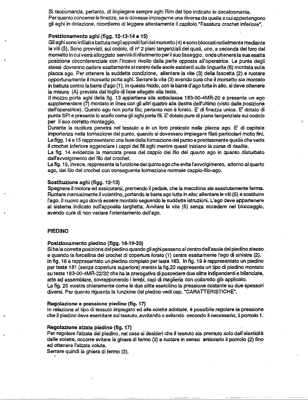
Si raccomanda, pertanto, di impiegare sempre aghi Rim del tipo indicate in decalcomania.
Perquanto concerne
gli aghi in dotazione, ricordiamo di leggere anentamente il capitola 'Fasatura crochet inferiore'.
Ia
finezza, se si dovesse impiegarne una diversa
da
quella a cui appartengono
Posizionamento
Gli aghi sono infilati a banuta negli appositi fori del morseno (4) e sono bloccati radialmente medianle
Je
viti (5). Sono prowisti, sui codolo, di
morseno in cui
posizione circonferenziale con J'incavo rivolto dalla parte opposta all'operatrice. Le punte degli
stessi dovranno cadere esattamente al centro delle asole esistenti sulla Jinguena (6) montata sui
placca
opportunamente il morsetto porta aghi.
in
Ia
II
supplementare (7) montato in
dell'operatrice). Questa ago non porta
punta SPI e presenta lo scalfo come gli aghi porta
per
Durante
importanza nella formazione del punta, quando si dovessero impiegare filati particolari molto fini.
Le tigg.
il crochet inferiore agganciare i cappi dei
La
dall'awolgimento del file del crochet.
La
ago,
ago. Per ottenere
battuta contra
misura (A) prevista dal foglio di lase all!lgato alia testa. .
mezzo porta aghi della fig.
il suo correno montaggio.
Ia
14
e 15 rappresentano una lase della formazione del punto e precisamente quells
fig. 14 evidenzia
fig. 15, invece, rappresenta
del file del crochet con conseguente formazione normale cappio-filo-ago.
aghi
(tigg.12-13-14
verra alloggiato servira di riferimento peril suo fissaggio, onde onenere Ia sua esatlla
Ia
suddetta condizione, allentare
Ia
barra d'ago
cucitura penetra nel tessuto e in
Ia
(1
).
13
linea con gli
mancata presa del cappio del filo del quarto ago in quanta disturbato
Ia
funzione del quinto ago che evita l'awolgimento, attorno al quarto
e 15}
no
2 piani tangenziali dei quali, uno, a seconda del foro del
Ia
vile (3) della fascena (2) e ruotare
Serrare
In
questa modo, con
appartiene alia sonoclasse 183-00-4MR-20 e presenta un ago
file; pertanto non e forato.
Ia
vile (3) avendo cura che il morseno sia montato
Ia
barra d'ago tuna in alto, si deve ottenere
aHri
quattro alia destra dell'ultimo (visto dalla posizione
E'
di finezza unica. E' dotato
fiJi.
E'
dotato pure di piano tangenziale sui codolo
un
foro praticato nella placca ago. E' di capital·e
fiJi
aghi mentre questi iniziano
Ia
corsa di risalita.
che
di
vede
Ia
Sostituzione
Spegnere il motore ed assicurarsi, premendo il pedale, che
Ruotare manualmente il volantino, portando
II
rage.
al sistema indicate sull'apposita targhetta.
avendo cura di non variare l'orientamento dell' ago.
PIEDINO
Posizionamento
Si
ha
Ia
e quando
In
fig.
16
per
teste
su teste 183-00-4MR-22/32 che ha
ad
atte
La fig.
20
diversi. Per quanta riguarda
Regolazione e pressione
In relazione al tipo di tessuto impiegato ed aile solene adottate, e possibile regolare Ia pressione
che
il piedino deve esercitare sui tessuto,
Regolazione
Per
regolare l'alzata del piedino, nel case si desideri che il tessuto sia premuto
delle solene, occorre svitare
ad ottenere
Serrare q'-!indi
aghi
(figg.
12-13}
Ia
macchina sia assolutamente Ierma.
Ia
barra ago tuna in alto; allentare le viti (5) e sostituire
nuevo ago dovra essere montato seguendo le suddene istruzioni. L'ago deve appartenere
Awitare
piedino
correna posizione del piedinoquando gli aghi passanoal centro dell'asola del piedino stessc• .
Ia
forcellina del crochet di copertura forato (1) centra esattamente l'ago di sinistra (2}.
(tigg.
16-19-20}
e rappresentato un piedino complete per teste 183.
181
(senza copertura superiore) mentre
Ia
prerogativa di possedere due slitte indipendenti e bilanciate,
assemblare, sovrapponendo i
mostra chiaramente come
Ia
funzione del piedino vedi cap. "CARATTERISTICHE'.
piedino
alzata
l'alzata voluta.
Ia
ghiera
piedino
di
termo (3).
(fig.
Ia
Jeinbi,
capi
Je
due slitte esercitino
(fig. 17)
awitando
17)
ghiera di fermo
Ia
vile (5) senza eccedere nel bloccaggio,
In
fig.
19
e rappresentato un piedino
Ia
fig.20 rappresenta un tipo di piedino montato•
di
maglieria con cellarette gia applicate.
Ia
pressione costante su
o svitando secondo il necessaria, il pomolo 1.
(3)
e ruotare in sense antiorario il pomolo (2) fino
due
solo
dall'elasticita
spessori
Page 11
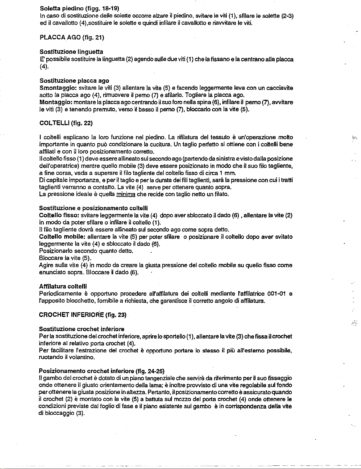
Soletta
In
ed il cavallotto (
piedino
caso di sostituzione delle solette occorre alzare
(figg.
18·19)
4)
,sostituire le solette e quindi infilare
il
piedino, svitare le viti
il
cavallotto e riawitare le viti.
(1
),
sfilare le solette (2·3)
PLACCA
Sostituzione
E' possibile sostituire
AGO
(fig.
21)
linguetta
Ia
linguetta (2) agendo sulle due viti (1) che
Ia
fissano e
Ia
centrano alia placca
(4).
Sostituzione
Smontaggio:
Ia
sotto
Montaggio:
le
viti (3) e tenendo premuto, verso il basso il pemo (7), bloccarto con
COL
TELLI
I cottelli esplicano
importante in quanto
affilati e con
II
coltello tisso (1) deve essere allineato sui secondo ago (partendo da sinistra evistodalla posizione
dell'operatrice) mentre
a tine corsa, vada a superare
Di capitale importanza, e
taglienti verranno a contatto.
La
pressione ideale e quella minima che recide con taglio netto un tilato.
Sostituzione.e
Coltello
modo
in
II
filo tagliente dovra essere allineato sui secondo ago come sopra detto.
Coltello
leggermente
Posi;::ionarlo secondo quanto detto.
Bloccare
Agire sulla vile (4) in modo da creare
enunciato sopra. Bloccare il dado (6).
placca
svitare le viti
placca ago (4), rimuovere il pemo
montare
(fig.
il loro posizionamento corretto.
fisso:
da
svitare leggennente
poter sfilare o infilare il coltello
mobile:
Ia
Ia vile (5)
ago
(3)
allentare
Ia
placca ago centrando
22)
Ia
loro funzione nel piedino.
puc
condizionare
quello mobile
il
filo tagliente del coltello fisso di circa 1 mm.
peril
taglio e per
La
vile
posizionamento
allentare
vite (4) e sbloccato
..
Ia
vile
Ia
Ia
(3)
deve essere posi;::ionato in modo che il suo filo tagliente,
(4)
serve per ottenere quanto sopra.
coltelli
Ia
vile
(5)
per poter sfilare o posizianare il coltello dopo
il
dado (6).
Ia
giusta pressione del cottello mobile su quello tisso
vile
(5)
e facendo leggennente leva con un cacciavite
(7)
e sfilarlo. Togliere
il
suo foro nella spina (6), infilare il
La
rifilatura
cucitura.
Ia
durata dei fili taglienti, sara
(4)
(1
Un
taglio perfetto si ottiene con i cottelli bene
dopo aver sbloccato il dado (6) , allentare
).
Ia
placca ago.
Ia
deltessuto
Ia
vile (5).
e un'operazione motto
pressione con cui i tratti
pemo
(7),
Ia
aver
awitare
vile (2)
svitato
come
Affilatura
Periodicamente e opportune procedere all'affilatura dei coltelli mediante l'affilatrice 001·01 e
l'apposito blocchetto,
CROCHET
Sostituzione
Per
Ia
inferiore
Per
ruotando
Posizionamento
II
gambo
onde ottenere
perottenere
il crochet (2)
condizioni previste dal foglio di
di
bloccatJgio (3).
coltelli
fornibile a richiesta, che garantisce il corretto angolo di affilatura.
INFERIORE
crochet
sostituzione del crochet inferiore, aprire lo sportello
al relativo porta crochet (4).
facilitare l'estrazione del crochet e opportuno portare lo stesso il piu all'estemo possibile,
il volantino.
crochet
del crochet e dotato di un piano tangenziale che servira da riferimento
il giusto orientamento della lama; e inottre
Ia
giusta posizione in aftezza. Pertanto, il posizionamento corretto e assicurato quando
e montato con
(fig.
23)
inferiore
inferiore
Ia
vite
(1
), allentare
(fig. 24-25)
prowisto
(5)
a battuta sui mozzo del porta crochet (4) onde ottenere le
lase e il piano esistente sui gambo e in corrispondenza della vile
Ia
vile (3) che fissa il crochet
peril
suo fissaggio
di una vile regolabile sui
Iondo
Page 12

La distanza
vite (6). Dopo aver sbloccato quesl'ultima, si
ottenere Ia quota del foglio di lase.
Anche Ia distanza H Ira
vile
(6) (fig. 24) facendo scorrere il porta crochet (4) sui suo albero (fig. 25).
0,
Ira Ia punta del crochet quando si trova tutto a sinistra e
lara ruotare
Ia
punta del crochet e il Iondo delle scalfo dell' ago si ottiene agenda sulla
il
porta crochet (4) sui suo albero fino
I'
ago, si ottiene agenda sulla
ad
CROCHET
Sostituzione e posizionamento
Per soslituire il crochet forato e necessaria togliere il collello mobile 3 (fig.22), togliere Ia controlama
7 (fig. 22) e ruolare il crochet cieco.
Procedere pertanlo come segue:
• Allentare Ia vile 5 che Iissa il coltello mobile 3 (fig. 22) e sfilarlo.
- Svilare le n°2 viti 8 (fig. 22) ed asportare
- Allentare
A questa punta allentare
Peril
(fig. 26) facendo in modo che, al !ermine della sua corsa verso sinistra, venga rispettata Ia quota
L riportata sullo schema di fasalura.
Riposizionare il crochet cieco come indicate nel paragrafo precedents e rimontare
7 e
Ia
staffa 9, bloccandola con le due
precedents (fig. 22).
Sostituzione e posizionamento
Per
Ia sostiluzione del crochet cieco (1) allentare
stesso, fino a poterlo sfilare dal suo perno (3).
presente che il crochet cieco e esattamente posizionalo quando, al punto morto sinistro, rispetta
quota M del foglio di fasatura.
Per
Ia posizione corretta in altezza verificare che
del crochet, sia sicura
quello forato (4).
Dl
COPERTU.RA
crochet
Ia
vile
2 (fig. 27) che Iissa il crochet cieco e ruotare quest'ullimo verso destra.
Ia vile 1 (fig. 26) e sfilare dal suo
montaggio, infilare il crochet !erato a batt uta e senza gioco sui suo
viii
crochet
e,
nella stesso tempo, verificare che il crochet cieco (1) non interferisca con
forato
(figg.
22-26-27)
Ia
staffa 9 (fig. 22); togliere Ia controlama 7.
pemo
il crochet !erato.
8 ed il coltello mobile, rispettando le istruzioni del paragrafo,
cieco
(fig.
27)
Ia
vile (2) e ruotare in sense antiorario il crochet
Peril
montaggio operare in sense inverse, tenendo•
Ia
presa del file di copertura
pemo
e bloccare Ia
Ia controlama
da
parte dell'uncino•
vile
Ia
1
SPINGI AGO E
Tulle
le teste
aghi (nella direzione del trasporto) durante Ia lore penetrazione nel tessuto nel memento in cui il
crochet aggancia i fili degli aghi.
II
sistema e tale
spingi aghi, senza essere frizionati e conseguentemente riscaldati.
Regolazione
Lo spingi aghi (1)
crochet. Una specials chiavetta (5) ricavata dal supporto e sporgente
impegna un'asola ricavata nel basamento, perrnettendo al supporto porta spingi-ago
selamente il moto rettilineo alternate dell'albero e non quello oscillante.
Lo spingi aghi dotato di un gambo cilindrico e montato in
e fissato a quest'ullimo
L'esatta posizione in
nella cruna dell' ago destro, quando
risalendo al punta morto superiore (dell. A).
Trovata l'ottimale posizione in
a questo
supporto porta spingi ago.
per
SALVA
181
e 183 sono delate di spingi aghi e salva aghimobili per evilare Ia deviazione degli
per
spingi
AGHI
cui gli aghi vengono a trovarsi a
aghi
mobile
(figg.
28-29)
'sandwich'
rispetto aile piastrine salva aghi-
e montato su un supporto (4) che, a sua volta, e montato 'folie' sull'albero porta
su
un piano orizzontale,
di
un
foro verticale praticato nel supporto
per
mezzo di una fascetta.
allezza e quella che vede
Ia punta del crochet inferiore si trova in asse
allezza,l'anellino
mezzo della vile (2), dopo aver fatto combaciare
Ia
linea di smusso della paletta spingi aghi centrata
con
I'
ago che
(3)
infilato nel gambo delle spingi
Ia
sua faccia inferiore centro il
aghi
verra fissato
ricevere
ed
sta
La regolazione radiale invece, si ottiene ruotando lo spingi ago fino a porto a contatto con tutti e
quattro gli aghi senza
La regolazione longitudinale si ottiene ruotando a mano
posizione tutto indietro (lantana dall'operatrice).
lo spingi ago agli aghi, facendo attenzione che questi, flettendo, non interferiscano con il crochet
(fig.29).
Si blocca Ia vile (8) (fig. 28).
pero fletterli (fig. 29). Si strings quindi a Iondo Ia
it
volantino fino a portare lo spingi ago nella
Si
svita quindi
Ia
vile
(6) (fig. 28).
vile (8) e si accosta il ferrno (7) e
Page 13
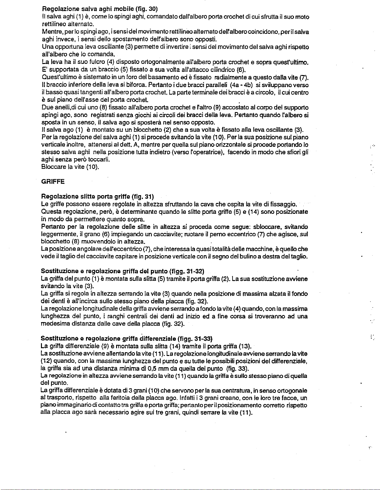
Regol~zione
II
sa iva aghi (1)
rettilineo alternate.
Mentre, per lo spingi ago, i sensi del movimento rettilineo altematodell'albero coincidono,
aghi invece, i sensi
Una opportuna leva oscillante (3) permette di invertire i sensi del movimento del salva aghi rispetto
all'albero che lo comanda.
L~
lev~
E'
supportata da un braccio
Ouest' ultimo e sistemato in un foro del basamento
II
braccio inferiore della leva si bilorca. Pertanto i due bracci paralleli (4a • 4b) si sviluppano verso
il basso quasi tangenti all'albero porta crochet.
salva
aghi
mobile
e,
come lo spingi aghi, comandato dall'albero porta crochet di cui sfrutta
delle spostamento dell'albero sono opposti.
ha il suo fulcro (4) disposto ortogonalmente all'albero porta crochet e sopra quest'ultirno.
(fig. 30)
(5)
fissato a sua votta all'attacco cilindrico (6).
ed
e fissato radialmente a questo dalla vile (7).
La
parte terminale dei bracci e a circolo, il cui centro
il
suo moto
peril
salva
e sui piano dell'asse del porta crochet. .
anelli,di cui uno (8) fissato all'albero porta crochet e l'attro (9) accostato
Due
ai
spingi ago, sono registrati senza giochi
sposta in un sense, il salva ago si spostera nel senso opposto.
II
salva ago (1) e montato su un blocchetto (2) che a sua votta e fissato alia leva oscillante (3).
Per
Ia
regolazione delsalva aghi
verticale inoltre, attenersi al dett.
stesso salva aghi
aghi senza
Bloccare
GRIFFE
Ia
perc
vile
nella posizione tutta indietro (verso l'operatrice), facendo in modo che sfiori gli
toccarli.
(1
0).
(1)
A,
mentre per quella sui piano orizzontale si precede portando lo
circoli dei bracci della leva. Pertanto quando l'albero si
si precede
sv~ando
Ia
v~e
(1
0). Per
a!
corpo del supporto
Ia
sua posizione sui piano
-:.
Regolazione
Le griffe possono essere regolate in altezza sfrut1ando
Questa regolazione,
in modo
Per:tanto per
leggermente,
blocchetto (8) muovendolo in altezza.
La
posizione angolare dell'eccentrico (7), che interessa
il taglio del cacciavite capitare in posizione verticale con il segno del bulino a destra del taglio.
vede
Sostituzione e regolazione
La
griffa del punto (1) e montata sulla slitta
svitando
La
griffa si regola in altezza serrando
dei denti e all'incirca sullo stesso piano della placca (fig. 32).
La
regolazione longitudinale della griffa
lunghezza del punto, i ranghi centrali dei denti ad inizio ed a fine corsa si troveranno ad una
medesima distanza dalle cave
Sostituzione e regolazione
La
griffa dillerenziale (9) e
La sostituzione
(12) quando, con
Ia
griffa sia
La
regolazione in altezza
del punto.
La griffa differenziale
al trasporto, rispetto alia
piano immaginario di contatto tra griffa e porta griffa; pertanto peril posizionamento corretto rispetto
alia placca ago
slitte
porta
griffe
(fig. 31)
perc, e determinante quando le slitte porta griffe (5) e (14) sono posizionate
d~
permettere quanto sopra.
Ia
regolazione delle slitte in attezza si proceda come segue: sbloccare, svitando
il
grano (6) impiegando un cacciavite; ruotare
griffa
del
punto
(5)
Ia
vile (3).
Ia
vile
(3)
awiene
della placca (fig. 32).
griffa
differenziale
montat~
ad
awiene
una
allentando
Ia
massima lunghezza del punto e su
distanz~
minima di 0,5 mm da quella del punto (fig. 33).
awiene
e dotata di 3 grani
fer~oia
sara necessaria agire sui tre grani, quindi serrare
sulla slitta (14)
Ia
v~e
(11
). La regolazione
serrando
della placca ago. lnfatti i 3 grani creano, con le !oro
Ia
(1
0) che servono per
Ia
cava che ospita
il
pemo eccentrico (7) che agisce, sui
Ia
quasi tota!Ha delle macchine, e quello che
(figg.
31-32)
tram~e
vile (11) quando
il porta griffa (2). La sua sostituzione
quando nella posizione di massima alzata il Iondo
serrando a Iondo
(figg. 31-33}
tram~e
tut1e
Ia
vile (4) quando, con
il porta gritfa (13).
long~udinale
le possibili posizioni del differenziale,
Ia
griffa e sullo stesso piano di quella
Ia
sua centratura, in sensa ortogonale
Ia
vite
Ia
vile di fissaggio.
awiene
(11
serrando
).
Ia
massima
tre
facce, un
awiene
Ia
vile
Page 14
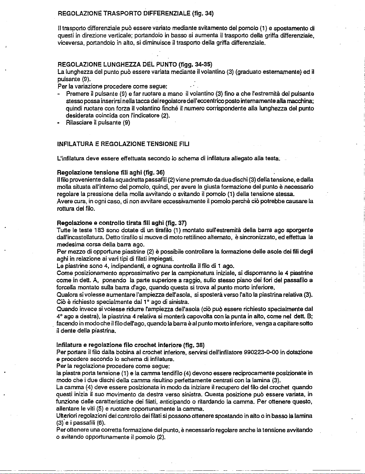
REGOLAZIONE TRASPORTO DIFFERENZIALE
II
trasporto differenziale puo essere varia to mediante svitamento del pomolo (1) e spostamento di
questi in direzione verticale; portandolo in basso si aumenta
viceversa, portandolo in alto, si diminuisce
il trasporto della griffa differenziale.
(fig.
34)
il
trasporto della griffa differenziale,
REGOLAZIONE LUNGHEZZA DEL PUNTO (fig g. 34-35)
La lunghezza del punto puo essere variate mediante il volantino (3) (graduate estemamente) ed il
pulsante (9).
Ia
variazione procedere come segue:
Per
- Premere
il pulsante (9) e far ruotare a mano il volantino (3) fino
ache
l'estremita del pulsante
stesso possa inserirsi nella tacca del regolatore dell' eccentrico posto intemamente alia macchina;
quindi ruotare con forza
il volantino finche il numero corrispondente alia lunghezza del punto
desiderata coincide con l'indicatore (2).
- Rilasciare il pulsante (9)
INFILATURA E REGOLAZIONE TENSIONE FILl
L'infilatura deve essere effelluata secondo lo schema di infilatura allegate alia testa;
Regolazione
II
filo proveniente dalla squadretta passafili (2) viene premuto da duedischi (3) della tensione, e dalla
molla situate all'intemo del pomolo, quindi, per avere
regolare
Avere cura, in ogni caso, di non avvitare eccessivamente
tensione
Ia
pressione della molla avvitando o svitando il pomolo (1) della tensione stessa.
fili
aghi
(fig.
36)
Ia
giusta formazione del punto e necessaria
il
pomolo perche cio potrebbe causare
rottura del filo.
Regolazione e
Tutte le teste
dall'incastellatura. Detto tirafilo si muove di moto
controllo
183
sono dotate di un tirafilo (1) montato sull'estremita della barra ago sporgente
tirata
fili
aghi
(fig.
37)
rellilineo
a~emato,
e sincronizzato, ed effettua
medesima corsa della barra ago.
Per mezzo di opportune piastrine (2)
e possibile controllare
Ia
forrnazione delle asole dei fili degli
aghi in relazione ai vari tipi di filati impiegati.
Le piastrine sono 4, indipendenti, e ognuna controlla il filo di 1 ago.
Ia
Come posizionamento approssimativo per
come in
dell. A, ponendo
Ia
parte superiors a raggio, sullo stesso piano dei fori del passafilo a
campionatura iniziale, si disporranno le 4 piastrine
forcella montato sulla barra d'ago, quando questa si trova al punto morto inferiore,
l'a~o
Ia
Qualora si vole sse aumentare l'ampiezza dell'asola, si spostera verso
piastrina relativa (3).
Cio e richiesto specialmente dal 1 o ago di sinistra.
Quando invece si volesse ridurre l'ampiezza dell'asola
4°
ago a destra),
_ facendo in modo che il filo dell'ago, quando
il
dente della piastrina.
lnfilatura e regolazione
Ia
piastrina 4 relative si monteril capovoka con
Ia
barra e al punto morto inferiore, venga a capitare sollo
fila
crochet
inferiore
(cio puo essere richiesto specialmente dal
Ia
punta in alto, come nel dell.
(fig. 38)
Per portare il filo dalla bobina al crochet inferiore, servirsi dell'infilatore 990223-0-00 in dotazione
e procedere secondo lo schema di infilatura.
Ia
regolazione procedere come segue:
Per
Ia piastra porta tensione (1) e
modo che i due dischi della camma risultino
Ia
camma tendifilo (4) devono essere reciprocamente posizionate in
perfellamente centrati con
Ia
lamina (3).
La camma {4) deve essere posizionata in modo da iniziare il recupero del filo del crochet quando
questi inizia
funzione delle caratteristiche dei filati, anticipando o ritardando
allentare le viti
Ukeriori regolazioni del controllo dei filati si possono ottenere spostando in alto o in basso
il suo movimento da destra verso sinistra. Questa posizione puo essere variate, in
Ia
(5)
e ruotare opportunamente
Ia
camma.
camma.
Per
ollenere questo,
Ia
lamina
(3)' e i passafili (6).
Per ottenere una corretta formazione del punto,
e necessaria regolare anche
Ia
tensione
awitando
o svitando opportunamente il pomolo (2).
Ia
Ia
8;
---------.
--~----
--------
Page 15
lntilatura e regolazione
I!
file (o ifili) provenienti dalla squadretta passafilo
sulla squadretta passafilo, l'altra (4) vicina ai crochet di copertura.
Quest'ultima
Pertanlo
compromettere
Per
Ia
rapporto passa file a forcella (5).
Bloccare
MANUTENZIONE
Sene
qui
Ia macchina sempre in perfetta efficienza: ·
OGNI GIORNO:
- pulire tutti gli organi della macchina relativi altrasporto, alia formazione del
- controllare
OGNI SETTIMANA:
smonlare
e lo spingi asola
lubriticare a mane
cosi come
e quella che deve dare
Ia
tensione
Ia
corretta tensione del file.
regolazione della tirata del file, allentare
Ia
vile (6).
di
seguito elencate le operazioni periodiche di manutenzione necessaria
illivello dell'olio ·
Ia
palcca ago e pulire, soffiando con aria compressa, le griffe ed i crochet, il salva ago
il
perno del pertacoltello mobile (fig. 22).
fili
crochet
(1)
posta sulla squadretta
le superciti evidenziate
di
copertura
Ia
giusta tensione al file,
(fig. 36)
(2)
passano attraverso due tensioni, una (1) pesta
in
prossimita dei crochet di copertura.
(2)
deve essere meno chiusa, senza pen)
Ia
vile
(6) e prowedere
in
rosso dei perni degli snodi sopra
a spostare vertical mente
per
mantenere
punic
ed i coltelli
il
piedino (fig. 16),
il
OGNI SEI MESI:
- sostituire l'olio e pulire il finro principale (fig. 39). .
per scaricare l'olio dalla bacinella togliere iltappo
Per accedere al filtro, togliere
fissano il supporto filtro
(fig. 39), dope averla
Togliere
pressione.
lnfilare sulle colonnine del supperto
za
quest'ultimo con
Rimontare
relativa guamizione (1) e
Effettuare quindi il rifomimento dell'olio osservando
mento olio"
il filtro montato sui supperto filtro olio, pulirlo con benzina e soffiarlo con aria a bassa
dell'anello di tenuta e della sua corretta posizione nella gola del supperto. Rimontare
il
distanziale (4) ed
awitata
il
filtro, fissandolo con
Ia
vile(6)
olio alia bacinella e sfilarlo, aiutandosi eventual mente con una chiave
nel foro centrale delle stesso.
il
fondello
Iappe (3)
il
fondello
il tiltro, imbevendolo con olio pulito. Assicurarsi dell'efficien-
le
sue due viti.
(5)
di
gemma (3) e svitare
(5) e il
distanziale (4). Svilare le due viti che
fissandoli con
le indicazioni riportate al capilolo "Ritomi-
Ia
Ia
vile (6). Rimontare
vile
(2).
Ia
vile (2) con
Page 16

ANOMAUE
DOVUTE A IMPROPRIA CONDUZIONE DELLA MACCHINA
PROBABILI INCONVENIENT!
Trasporto e sbandamento del tessuto
Bucatura
Punto irregolare
Saito del punto
del tessuto
CAUSE PROBABILI
-
Pressione del piedino insufficiente
Griffe mal regolate in altezza ed inclinazione
Coltelli
Differenziale mal regolato
-
- Aghi spuntati
- Aghi di finezza non appropriata alia placca
Aghi con punta non adatta
-
- Tensioni mal regolate
Tendifili mal regolati
-
lnfilatura sbagliata
- Filati non calibrati
- Crochet inferiore mal regolato rispetto agli
aghi con conseguente spuntatura del crochet
Spingi asola e salva aghi troppo slaccati
dagli aghi
- Aghi mal posizionati
- Tensioni mal regolate
- Camma tendifilo crochet inferiore mal regolata
da affilare -
Rottura ago
Rottura
Perdita olio
Mancanza
filo
di
lubrificazione
Aghi storti
Aghi
mal montati
- Salva aghi mal posizionato
- Tensione troppo serrata
- Filo
- Spingi asola mal posizionato
- Serraggio bacinella mal effettuato
- Guamizioni bacinella mal sistemate
- Carters braccio e base insufficientemente
- Guamizione tappo del filtro inefficiente
- Livello olio troppo basso
- Passaggi olio intasati
awolto
Tappo scarico
fondo
bloccati
Filtro pompa lubrificazione intasato
irregolarrnente sulla bobina
olio bacinella non serrato a
Page 17

181-183
- '
Page 18

WARNING
SAFETY
The
driving motor and
THE
MAINS SUPPLY BEFORE:
machine threading
substituting sewing parts
machine maintenance work
leaving the work station even momentarily
The
Rimoldi products to which this booklet
devices foreseen
The
silencers mounted on pneumatic equipment are also considered safety devices and
in case
not
with the motor disconnected from the mains supply by means
Rimoldi
above-mentioned basic safety rules.
GUARANTEE
of
malfunction,
be
removed and then replaced except. in the case
S.r.l. declines
by
any
equipment mounted on the machine MUST
or
any access to internal parts
refeJ:S
come complete with all
law.
must
be cleaned but not cut out. Therefore, the safety devices fitted must
of
any
liability for accidents deriving from
BE
DISCONNECTED FROM
the
accident prevention
maintenance operations and then only
of
the switch provided
the
inobservance
for
of
even one
the
purpose.
as
such,
of
tbe
Rimoldi products are submitted to scrupulous inspections and rigorous tests that
to
guarantee their duration and efficiency. However their performance depends,
extent,
The
be
of
Rimoldi
Rimoldi Original Spare Parts are used.
Rimoldi
and
on
the
way
in which these products are used and on their careful maintenance.
exclusive use
identical in quality to
Rimoldi products
S.r.l. declines
S.r.l. reserves the right to
information given in this handbook.
of
Rimoldi Original Spare Parts, trade-marked Rim,
the
factory-mounted parts, assures the serviceability and commercial value
over
time.
any
liability
for
amend
malfunction
or
change,
the
only ones guaranteed
or
damage to its products where parts other
for
technical
or
commercial reasons, the data
make
it possible
to
a considerable ·
to
than
Page 19

INTRODUCTION
PRESENTATION
GENERAL INSTRUCTIONS
CHARACTERISTICS
ELECTRIC SYSTEM .
CONNECTION DIAGRAMS
INSTALLATION
Fitting the plate on column stand
Fitting the
plate on adjustable stand
Fitting the motor
Fitting the shock absorbers
Fitting the machine head
Machine head-motor connection
Connection
of
presser foot lifter
CONTENTS
OILING
REPLACING
AND ADJUSTING SEWING PARTS
Notes on upper and lower shaft phasing
Needles
Presser foot
Needle plate
Knives
Lower
looper
Spreading upper looper,
with hole
.•
·blind
Front and rear needle guards
Feed dogs
ADJUSTING
ADJUSTING
THE
DIFFERENTIAL FEED
THE
STITCH LENGTH ' THREAD TENSIONS
Adjusting the needle thread tension
Adjusting and checking the
needle thread pull
Threading and sdjusting the lower looper thread
Threading and adjusting the spreader
MAINTENANCE
looper threads
FAULTS
DUE
TO
IMPROPER USE
OF
MACHINE
-:··-·
-
__
I
Page 20

PRESENTATION (fig. 1)
1
2
3 Presser foot
4 Presser foot
Needle thread and covering thread tension
Presser knob
lift
knob
lift
ring nut
5 Needle thread puller
6
Upper covering thread tensioner
7 Shutter for looper threading
8
9
10
11
Movable knife holder
Stitch regulating button
Cover for tension and lower looper thread cam
Differential control mechanism cover opening button
::-·
12
13
14
Differential ratio adjustment knob
Oil level sight glass
Oil refilling cap
Page 21

CHARACTERISTICS
1)
Frame:
cylinder bed
The
parallel to
movement
tiring and physical injury overtime.
studies and
to
.
The
balanced line.
The
2)
tum
The
described
to
two
centre
Therefore
achieve this,
this consists
which
allows extremely small diameter tubular pieces
special configuration
the
feed direction raised above the horizontal structure, allows
in
the
work
various
ergonomic principles •
delicate colours, which are a quality
main
shafts
in
an
anticlockwise direction.
link
between
by
the
obstruct
planes:
of
the
one
the
the
there
surveys at a large number of clothes making workshops,
of
the
the
conjunction
operator
horizontal belonging
upper
shaft.
drive
batt path lies on two
are three cogged pulleys and a flat surface which acts
of
a traditional-shaped upper arm and a small-size feed-off-the-arm
to
be
assembled.
of
the base, which has a small-dimension cylindrical extension
the
operator free
zone
and
keeps their head
The
special machine shape was designed
of
Rimoldi products, give the machine a
upper
arm
and lower structure
two shafts is not direct, i.e. it is not located
of
the centres
when moving the garment
to
the lower shaft and one vertical which arrives at
planes
of
rotation
and
torso in an optimum position to avoid
after
and
sober
are
connected by a special bett, and
on
the
inclined
of
the
two
shafts. In fact, in
on
the
right of
at
right angles
the
needles, it is located
to
each other. In
as
a bett tensioner.
thorough
according
order
order
well-
plane
not
on
the
to
"Differential"
3)
behind
feeding
independently
differential ratio, i.e.
is carried out
ofthe
A suitably connected device, supplied on request, which can
by pneumatic piston allows
4)
Needle
by
attached
A
is connected
main shaft, is joined
The
and
a perfect stitch.
5)
Stitch
frame at
By
length can
to
the
the
operator. By moving the knob downwards, the path increases, vice versa, it decreases.
the
rotating
pin
fixed
attemating rectilinear motion transmitted by the needle
deceleration
regulator.
pressing
be
carried
feed.
The
needle
cloth.
bar.
to
a con-rod which is in
to
the
be
and
the other in front
The
path
from
the
back
the
very
simply
The
needle
upper
shaft. The shaft causes a type
the
machine
to
the
other
to
a pin at right angles
are
in perfect synchrony with the lower looper movement
The
stitch regulator is
height
the
of
the
button
set. It is visible on
out
is
and
very
feed is
difference between
by
simple
the
"differential" type.
On
relation
of
the
front feed dog (therefore the main feed dog) can
one
in
order
to
obtain a differential feed.
the
unscrewing
the
differential ratio
bar
moves with
arm
acts
end using a joint. The above mentioned con-rod, ccintrolled
operator's abdomen. ·
turning the machine arm handwheel
the
and
the
knob located
an
tum
attached
as
a fulcrum at
to
the
button type located on the horizontal part
graduated scale
needs very little time.
Two
feed dogs,
to
the
feed direction), contribute towards
path
of
the
front feed
on
the
be
to
be
changed when
alternating rectilinear motion
3leverto
to
a pin on the lever.
one
the lever in
on
oscillate through a
end
of
the
the
middle
bar
the handwheel itself.
of
which
The
dog
lower part
knee-controlled
the
machine
lever while
between
is such that its acceleration
by.
hand
one
is located
be
adjustment
and
the
back
of
the
base
or
controlled
is running.
and
is controlled
crank
the
needle
the
two ends.
in
order
the
required stitch
The
operation
adjusted
of
the
one,
in front
button
bar
by
the
to
form
of
the
.-;··
6)
Lower
a cylindrical shaft. It
angles
direction
Both
the
looper
to
the
of
the
movements
second,
the
movement.
moves
feed
and with a simuttaneous rectilinear motion on a plane parallel
feed.
can
rectilinear one, according
The lower looper is mounted on a looper holder which is part
with
an
atternating oscillatory motion on a vertical plane
be
adjusted: the first one when the needle and looper
to
the thickness
of
the
needles.
are
at
to
phased
of
right
the
and
Page 22

7) Needle
and are mobile. Their task is to prevent the needle from bending (in the feed direction) when
they penetrate the fabric. This is carried out by brushing against the needles when the loops
of
The
guard blades without rubbing and therefore heating up. This therefore avoids negative
consequences when synthetic fibres are used.
guard
needle thread are hooked by the looper.
control mechanism causes the needle
and
rear
needle guard. Both devices are driven
by
the looper holding shaft
to
find itself sandwiched between
the
two
needle
8)
9)
10)
Upper
in contact with the presser foot, is carried out by a kinetic mechanism.lt is
and is driven by a key which protrudes from
two
which each have a sickle-shaped blade and
-
-
The
takes
that
are
This
threads.
Trimming
fixed to the presser foot in a horizontal position and a mobile blade fitted to a support which
moves with
The
foot. The presser foot has a groove in the middle of its sole at
that closes after the blades and before the area where the needles come down.
blade stop acts against the fixed stop with a pressure which can be adjusted according
the
The
Presser
with
the
unit and rest for the moving blade. For this reason, it would be very uneconomical
ofthe
dogs when chain stitch is produced beyond the end of the material, which is something that
occurs with all presser feet. Natural wear would frequently force
unit. In order
under
and adhere to the underside of the presser foot. This arrangement prevents the body
presser foot from wearing and makes replacement easy when
There are different types of sole plates:
a) with different thicknesses according to
b) more
c) which special shapes
· Rnally, a special device prevents the sole plates from flattening and allows
their
looper
loopers
one
with a hole
the
other, blind
looper with the hole is the one which holds
up the thread carried by the one with
during their stroke the two left needles are in front of
behind.
system ensures that the cover thread is correctly arranged compared
cut of the fabric edges, which are turned upwards, takes place in the middle
weight
cutting angles are designed to attain perfect trimming of the edges.
the
two cover loopers moving. It also acts as a support for the fixed blade
presser foot came into contact with the material during the feed
the
elastic force so that very fine and light fabrics can be fed without damaging them.
movement
knives.
an
of
fool
feed dog in feeding the material (its main task), incorporates parts in order
sole. Under the weight
or
less arched.
The
atternating oscillatory motion.
the
material used.
The body
to
avoid this problem, two arched hardened steel spring sole plates are located
The laying
trimming knives are located
of
the presser foot is a small device which, apart from cooperating
to
carry out stitching with overlapping edges.
of
the cover thread on the upper surface
the
lower part
are
clamped to
the
cover thread.
the
hole with its hook-shaped end and lays it
on
of
the presser foot pressure springs,
the
weight of the fabric used.
of
the
two
The
the
cover thread while
the presser foot and include a blade
the
front which forms a passage
the
on
the
machine arm. It activates
vertical shafts:
other,
on
the
ofthe
trimming knife
or
directly with
the
user
to
replace a
the
sole
sole plates become worn.
them
of
the
seam,
presser foot
other hand,
so
the
right ones·
to
the needle
of
the
presser
The
mobile
to
to
set
if
the
sole
the
feed
cost~r
plates flatten
of
the
to
off-load
11)
Looper
looper thread.
an
A suitable easy
thread tensioners and a
a backup
thread
extension
to
tensioning
It is located in a box located on the left of the horizontal structure and fitted
of
the lower main shaft.
to
open cover protects and hides it. A plate which carries thread eyelets,
the operation of the cam and a complement in the thread regulation operation.
cam. A rotary blade thread tensioning cam controls
bar
between the two cam blades is located inside
the
same box
the
lower
teo
as
Page 23

12)
Lubrication.
structure. This pump is arranged
feed direction. It
It has
four
One
phase
lower shaft to lubricate the main bearings and mechanisms which operate in the lower part;
and through a connecting tube which distributes the
mechanisms
Two
phases
in
the
base
One
(the fourth)
phases together with the oil which has arrived there by gravity after lubricating
mechanisms is drawn
upper
right part
The lubrication is forced with a gear pump located in the lower horizontal
at
can
phases:
when
it
in
the upper part
when
under
the pump.
when
of
right angles
be
easily removed for maintenance.
draws
oil from the oil can indirectly. The oil is sent
of
the arm.
the oil is drawn from the nose
the
filtered oil brought down into the base
up
again. It is then pushed under the plexiglass
the
arm
to show that it is operating correctly.
to
tl\e
main lower shaft and parallel
under
oil to the arm main bearings
of
the arm and taken
by
the
back
above
cup
pressure
down
mentioned
located on
to
to
and
all
to a tank
the
lower
the
the
the
two
the
Having seen
the
a)
b) after carrying
gravity
the
c)
located on
d)
the
the
pump operation, here follows a summary
oil is
drawn
from
filtered oil from the base is drawn up and forced to pass under the transparent
oil drips down from the cup into the oil can.
from
the
oil can and forced to lubricate all the machine mechanisms;
out
this operation, the oil (partly drawn from the arm and partly returned
the base) is collected in a small
the
upper cover
of
the machine arm.
GENERAL INSTRUCTIONS
Before connecting
the
connection
the
motor cutout is
the
earth connections are correctly made.
The
direction
two
of
the
three poles in the connection plug, without touching the yellow-green earth wire.
should
is connected to
handwheel). ·
ELECTRIC
be
done
SYSTEM
the
motor
to
the mains supply make sure
of
the
terminal board inside the motor corresponds
set!
or
the same vottage and for the installed
of
rotation
if
the
the
of
the
motor
can be reversed (for three phase systems)
machine turns clockwise rather than anticlockwise
electric line (towards the operator, see the arrow on the belt guard
of
tank
in the base, under
that
the cycle phases:
the
pump;
to
the
working vottage;
power
of
the
motor
by
swapping
as
it should
when
cup
installed;
any
This
the
motor
near
the
by
The
electric system includes a motor cutout, the motor connection cable and
male
plug.
The
mains
connections must
cable
must
be
protected up to a height
which
is supplied on request.
In
all
types
of
connection it is absolutely necessary for the electric system
officially recognized earth with a green-yellow
Motor
The
and power
cover
(fig. 2).
cutout
setting (in ampere)
and
setting
oft
he
tum
the special screw (or slide the cursor index) until it shows
be
check
motor
used (fig. 2). In
made
by the user;
of
1.90 m from the floor with a rigid sheath,
(fig.
2)
of
the motor cutout should
for
or
visibly marked wire.
ordertocheckand
overhead connections (electric busway)
be
as shown in the table
adjustthe setting, remove
4.65
to
be
m
of
cable without
connected
for
the
the
required
vottage
the
cutout
value
to
the
an
Page 24

Attention:
Disconnect the power supply before removing the cover.
Light
connection
In order
to
have independent lighting, use Rimoldi device 019-90 and connect it
motorcutout input.
Input E = 125/160/220/240/380/415 Volt50/60 Hz.
Adjustable output U
Belt
guard
on
the
=from
motor
5to
12 Volt 220 VA
All types of motor supplied by Rimoldi together with the sewing machines are fitted with
suitable belt guards (fig. 3).
II
is
highly inadvisable
to
remove it before making sure the motor
is
turned off.
INSTALLATION
to
the
Fitting
The machine head has a base plate (14) especially studied
the
base
plate
for
machine
head (fig. 4)
to
suit either column stands
or
adjustable table stand. The same plate is used to support the motor and the bobbin holder.
Fitting
the
plate
on
adjustable
stand
(fig. 4-5)
Insert cylinder collar (11) of plate (14) on the column top and fix it with screws (14).
Fitting
the
plate
on
adjustable
stand
(fig.
4-6)
Rest plate (14) on the stand and fix it with screws (15), washers (16) and nuts (17).
Fitting
Fix the motor under base· plate (14
the
motor
(fig.
4-7)
-fig.
4) with bolts inserted into holes (18
-fig.
4), and washer
(19) inserted between the upper shock - absorber and the base plate.
For Quick motors insert plates (20) in holes (18) in the base plate, and insert rubber shock -
absorbers (21) under and over the motor support arm.
Fitting
Insert shock-absorbers (9) into conical holes
(1
the
shock -absorbers
(fig.
4)
{14)
made in the base plate, join them with spacer
0), which must project upwards, and fit washer (8) on the upper shock asbsorber. Screw pins
(3) in their places, and fit nurs (5) anto these pins underneath the base plate without locking them.
Place flanges (2) and shock-absorbers
(1
),
onto pins (3).
:-_
Fitting
the
m;~chine
head
(fig.
4)
Place the machine head on the base plate, and centre shock-absorber (1) and tube ends
FIX
their places on the machine head.
Level
the
machine head
by
turning pins (3), and then lock with nuts (5). Insert connecting rods
the machine with screw {13) and put washer {12) between.
(7) into tubes (6). Insert connecting rods (7) with tubes (6) attached into the holes in pins (3) and
of
screw the connecting rods into the base up to the end
MOTOR-HEAD
In
order
to
CONNECTION
connect the head
(fig.
8)
to
the motor it is necessary
the thread.
to
use a trapezoidal belt
shown in the figure.
a) Connect the lower machine pulley
to
the motor pulley with the belt in order to obtain the
working speed required by Rimoldi. Do not fit pulleys other than those provided by Rimoldi
in order to attain higher speeds.
b) Align the motor pulley with the driven pulley fitted
appropriately in slots (18) in support plate
(14-
fig. 4).
to
the head by moving
of
the
(1
0) into
dimensions
the
motor
Page 25

c)
Adjust the
tt
is
belt. The
the
beM
tension
not too tight, otherwise the pulley shafts could be overloaded, which reduces the life
beM
tension is correct when,
belt yelds by about 1 0-15 mm.
by
turning the motor fixing joint, so that it cannot slip, but make sure that
if
pressed by hand in the middle
of
the longer free part,
of
the
Connection
Join connecting rod (1) to presser foot
OILING
The
machine leaves the factory without lubricant, therefore
32M type oil
Proceed as
1) Unscrew transparent cap A
To
fill completely, pour in the entire oil contents
2)
3) Check that the
(fig,
of
presser
foot
lift
(fig.
9)
lift lever on the machine head with screw
7)
it
is necessary
for
industrial sewing machines, which is supplied as
follows:
(1
000 gr.), of
oil level comes close to the upper position between the
an
the
B.
4)
Screw transparent cap A on again.
5) Hand
6) Run
7)
IMPORTANT-
the
occur. Never mix different oils together.
The
-AGIP
•
MOBIL
-
TEXACO
WARNING:
in operation.
lubricate the articulated joint pin surfaces above the presser foot shown in red (fig. 16) as
well as the pin of the mobile knife-holder (fig. 22).
the
machine without thread for about 5 minutes, gradually increasing speed from 1500
r.p.m.
to
the operating speed.
While running, check the oil circulation through transparent refilling cap
The
oil level must always be between the two red lines. If it falls below the lower line,
lubrication becomes insufficient; on the other hand,
following can be used as substitutes for the prescribed oil:
OTE32
DTE LIGHT
REGAL OIL 32
Always make sure that the oil passes under transparent cap A when the machine is
if
it is above the upper line, oil leakage could
(2)c
to
fill it using special RIM
accessory, before starting up.
tin supplied with the machine.
two
red on oil indicator
A.
REPLACING
Phasing
Correct phasing between the shafts is
breaking
should
NEEDLES
The
left part
It is therefore always advisable to use Rim needles of the type shown in printing.
As
needles provided, please read the chapter "lower looper phasing" carefully.
Needle
The
tangential planes are provided
clamp
position with the
should fall into the exact centre of the slots on tongue (6) fitted
this,
needle
bar
be
machine has been set up with Rim needles. These belong to the system printed on
far
as
needles are slipped home in clamp holes
it is
loosen screw (3) making sure that
bar
in its uppermost position.
AND PHASING THE SEWING PARTS
the
upper
or
any other reason, the phasing between the shafts needs to be adjusted, specialist staff
contacted since the operation is highly complex.
of
the machine arm and have the same thickness
the
thickness is concerned, if needles are to be used of a different thickness from the
positioning
to
be
(1
).
and
lower
shafts
(figs.
12-13-.14
on
housed in, is used as a reference for fixing in order
hollow facing away from the operator. Their tips
In
this way, measurement (A) on the phase chart should be obtained when the needle
(fig.
11)
essential for correct machine operation. If, due
as
those supplied as accessories.
and
15)
(4)
and are locked radially with screws (5).
the shank, one of which, according to which
to
attain its exact circumferential
to
the needle plate. In order
the
clamp is fitted home against
to
the bett
the
upper
to
achieve
Two
---
----
Page 26

The
needle clamp in fig.
fitted in line with the other four on their right (as seen by the operator).
This needle does not carry thread; therefore it has no eye.
tip and a groove like those which carry the thread. It also has a tangential
plane on its shank in
While sewing it penetrates the material and a hole in the needle plate.
the formation of a stitch when particularly fine threads are used. Rg. 14
and 15 show a phase
thread as they begin
Rg.
14
shows the thread loop
winding looper thread. Fig. 15, on the other hand, shows the operation of the fifth needle which
prevents the looper thread winding around the fourth needle
formation.
13
belongs to subclass 183-00-4MR-20. It has a supplementary needle (7)
It
has only one thickness. It has an SPi
order
to
frt
it correctly.
It
is extremely important in
of
stitch formation, precisely when the lower looper hooks
the
upward stroke.
of
the fourth needle not being hooked due
and allows normal needle thread loop
the
loops
to
interference from
of
needle
the
Replacing
Stop the motor and press the pedal
manually to raise
needle. The new needle must be fitted
suggested on the needle system plate.
Tighten screw (5) without forcing it, and pay attention not
PRESSER
Presser
The
presser foot is in the correct position when the needles pass through the centre
the presser foot itself and when the fork of cover looper with hole (1)
centres left needle (2) exactly.
a presser foot for head
to
183-00-4MR-22/32 heads which has the characteristic
sleds.
Rg.
20 clearly shows how the two sleds exert a constant pressure on two different thicknesses.
far
as the presser foot operation is concerned, see the "CHARACTERISTICS" chapter.
Adjiusting
According
pressure exerted
necessary.
the
FOOT
foot
positioning
It is used
presser
to
the
needles
the
to
type
(fig.12-13)
to
make sure that the machine has stopped.
needle
assemble garments with collarettes already applied
foot
on
the fabric by the presser foot,
barto
its top dead center position; slacken screws (5) and replace the
by
following the instructions above. Use
to
alter
(fig. 16-19-20)
Fig, 16 shows a complete presser foot for head 183. Rg. 19 shows
181
(without top cover) whereas fig. 20 shows a type of presser foot fitted
of
having two independent balanced
pressure
of
fabric to be sewn, and
(fig. 17)
the
sole plates used, it
by
tightening
Tum
the
the
needle orientation.
by
overlapping the edges.
is
possible to adjust the
or
slackening knob {1)
the
needle system
handwheel
of
the slots in
As
as
Adjusting
To
adjust the presser toot lift when the fabric is to be pressed by the elasticity
only, slacken ring nut (3), and tum knob (2) in a
obtained.
Then lock ring nut (3).
Presser
In order
3), and
NEEDLE
Replacing
To
replace tongue (2), slacken the two screws
Replacing
Di~assembling:
needle plate (4), remove pin (7). Take off needle plate.
Assembling:
(3), and keep pin (7) pushed downward while locking it with screw (5).
the
presser
foot
sole
to
replace the sole plates, lift the presser foot, slacken screws
clips (4), replace the sole plates and clip, and tighten up
PLATE
the
tongue
the
needle
Slacken screws (3) and screw (5), and levering slightly with a
Rtthe·needle
plate
(fig.
foot
lift (fig. 17)
clockwise direction, until the required height is
(fig.
18-19)
21)
(1)
which fix and centre it
plate
plate by centring its hole on pin (6), insert pin (7), tighten up screws
the
(1
screws.
of
the
sole plates
), take off sole plates (2-
to
the plate (4).
screw-
driver under
Page 27

KNIVES
The
it can condition the sewing. A perfect cut can be obtained with well sharpened correctly positioned
knives.
Fixed knife (1) must be aligned with the second needle (from the left as seen
mobile knife (3) must be positioned so that
cutting edge of the fixed knife by about 1 mm at the end of its path.
The
the cutting edges. Screw (4) is used in order to obtain this.
The
(fig.
22)
knives carry out their task in the presserfoot. Fabric trimming is a very important operation since
by
the operator), while
its
cutting edge passes the
pressure between the two cutting edges
ideal pressure is the
minimum
which cuts a thread cleanly.
is
extremely important, both for the cut and the life
of
Replacement
Fixed
knife:
to
slip knife (1) in and out.
The
cutting edge should be in line with the second needle as descnbed above.
Moving
slightly and loosening nut (6). Position it as described. Tighten screw (5).
Tum
screw (4) in order to create the correct pressure between the mobile and fixed knives as
described above.
Tighten nut (6).
Sharpening
The
knives should be sharpened periodically with knife sharpener 001-01 and the special block
(supplied on request) which ensures the correct sharpening angle.
LOWER LOOPER
Replacing
To
replace the lower looper, open shutter (1), slacken screw (3), which fixes
holder (4).
To
facilitate uncoupling bring the looper as far out as possible,
Positioning
The
leg
of
obtain the correct orientation of the blade; an adjustable screw is also provided on the bottom in
order to obtain the correct height. Therefore, the correct position is ensured when looper (2) is fitted
with screw (5) home against
the
phasing chart, and the plane on the leg is against fixing screw (3).
Distance D, between the end of the looper when it is on the extreme left of the needle is achieved
using screw (6). When
distance
Distance H, between the end of the looper and the bottom
using screw (6) (fig. 24) by slipping looper holder (4) along its shaft (fig. 25).
and
positioning
loosen screw
knife:
loosen screw (5) in order to remove
the
knives
(fig.
23)
the
lower
looper
the
lower
looper
the
looper has a tangential plane which is used as reference when it is fixed in order
this screw is loosened, looper holder (4) is turned around its shaft until
on
the phasing chart is obtained.
of
the
knives
(4)
slightly after loosening nut (6). Loosen screw (2) in order
or
position the knife after loosening screw (4)
the
lower looper
by
turning the handwheel.
(fig.
24-25)
looper holder clamp (4) in order to obtain the conditions described
of
the needle groove
is
to
be able
to
its
to
on
the·
also obtained
:-···
·.:
COVER LOOPER
Replacement
In
order
blade stop 7 (fig. 22) and
Then proceed as follows:
- Loosen
- Loosen the two screws (8 - fig. 22) and remove bracket 9 (fig. 22); remove blade stop 7.
- Loosen screw 2 (fig. 27) which fixes the blind looper and tum it towards the right.
At
this point, loosen screw 1 (fig. 26) and remove the looper with hole from
In order
26) in such a
produced.
to
and
positioning
to
replace the looper with hole,
screw 5 which fixes mobile knife 3 (fig. 22) and remove
frt
the looper with hole, push it home onto its pin without play and lock down screw 1 (fig.
way
that, at the end
of
the
tum
the blind looper.
of
looper
it
with
hole
(fig.
22-26-27)
is necessary to remove mobile knife 3 (fig. 22), remove
it.
its leftward path, measurement L on the phasing chart is
its
pin.
Page 28

Replace the blind looper as shown in the previous paragraph and fit back blade stop 7 and bracket
by
locking it with the two screws (8) and the mobile knife according to the instructions in the
9,
previous paragraph (fig. 22).
Blind
looper
In order to replace blind looper
~can
until
operation in reverse, bearing in mind that the blind looper is in its correct
M on the phasing chart is obtained when
In order to obtain
same time, blind looper (1) does not interfere with looper
replacement
and
positioning
(1
),loosen screw (2) and turn the looper in
be slipped off pin (3). In order
the
correct height, check that the looper hooks the thread correctly and, at
(fig. 27}
to
Itt
~back,
~
is at
do the same
~s
left dead centre.
w~h
hole (4).
an
anticlockwise direction
pos~ion
if
measurement
the
NEEDLE GUARD AND REAR NEEDLE GUARD
All the
needles bending (in the feed direction) when they penetrate the fabric and at
181
and 183 heads are fitted with rear and mobile needle guards in order
to
prevent
the
moment when
the
the looper hooks the needle threads.
the
The system causes the needles to find themselves sandwiched between
two needle guard
blades without rubbing and therefore heating up.
Adjustment
Needle guard (1) is fitted
key (5), which protrudes from the support horizontally, engages a slot in
rear needle guard support
of
the
mobile
on
needle
guard
(fig. 28-29)
support (4) which, in turn, is "idle" on the looper holder shaft. A special
the
base and allows
to
receive the ahernating rectilinear motion of
the
shaft only and not its
the
oscillatory motion. ·
The
rear needle guard has a cylindrical leg and is fitted in a vertical hole made in
to
fixed
The
eye
the support using a clamp.
exact height is achieved if the line of the bevel of the rear needle guard blade
oft
he right needle when
the
end
of
the lower looper is on the axis of
the
needle
the
support; it is
fs
centred
as
it rises towards
on
the
its upper dead centre (draw. A).
Once the optimum height has been found, ring (3) on the leg
of
the
rear needle guard is fiXed using·
screw (2) after bringing its lower face flush against the rear needle guard
holder support.
Radial adjustment is done by turning the front needle guard until
needles,
w~hout
Lengthtways adjustment is obtained by
bending them (fig. 29). Then lock screw (6) (fig. 28).
manually turning the hand wheel until the front needle guard
comes into contact
w~h
all 4
it
reaches the extreme backward position (away from operator). Then slacken screw (8), push collar
(7} and
with
the
front needle guard up to the needles, paying attention that, the needles
the
looper (fig. 29) when they bend. Lock screw (8) (fig. 28).
do
not interfer•e
:::
..
Adjustment
Needle guard
of
the
mobile
(1
), like the rear needle guard, is driven
needle
guard
(fig.
30)
by
the looper holding shaft and exploits its
ahemating rectilinear motion.
While the directions
the
directions
of
ahemating rectilinear motion of the shaft coincide
of
shaft motion are opposite for the mobile needle guard.
Oscillating lever (3) allows the directions of the mobile needle guard movement to
relation to the shaft which drives
Fulcrum
by
(4)
of
the
lever is arranged at right angles above the looper holding shaft. II is supported
arm (5) which is fixed in tum to cylindrical fastening (6). This
fastening is located in a hole in the base and fixed
~-
radially to it with screw
forks.
Therefore the two
holding shaft.
The
parallel arms
final parts of each arm are circular with centre on
(4a-
4b) extend towards
the
base almost at a
plane of the looper holder axis.
Two
rings, (8) fixed to the looper holding shaft and (9) beside the body of
support, are adjusted without play to the circles of the lever arms.
the
Therefore, when
shaft moves in one direction, the needle guard moves in
for
the rear needle guard,
be
(7}.
The
lower lever arM
tangentto
the
the
mobile needle guard
the
oppos~e
reversed
the
looper
direction.
:-·:
ill
Page 29

Needle
needle guard
for
operator) so that it almost brushes against the needles without touching them. Tighten screw
FEED DOGS
guard (1) is fitted on block (2) which in turn is
(1
).
loosen screw
its position on the horizontal plane, push the mobile needle plate right back (towards the
(1
0). For its position
fiXed
to oscillating lever (3). In order to adjust
on
the vertical plane, follow drawing A, whereas
(1
0).
Adjustment
The
height
This
adjustment is, however, the determining factor when feed dog holding sleds (5) and (14) are
in positions which allow the above. .
Therefore, in order to adjust the height
slightly with a screw driver; turn off-centre pin (7) which moves block (8) upwards.
The
angular position
the
screw driver ends up in a vertical position with the burin mark on the right
of
the
tip.
Replacement
Main
feed dog (1) is frtted to sled (5) using feed dog holder
.of
the
feed
dog
holding
of
the
feed dogs can be adjusted by exploiting the hollow which houses the locking screw.
of
cam (7), which concerns almost all machines, should be
and
adjustment
of
sleds
(fig.
31)
of
the sleds proceed as follows: loosen nut (6)
the
main
feed
dog
(fig.
31-32)
(2).11
can be replaced
by
so
that the tip
by
loosening screw
unscrewing
(3).
The
height
of
the feed dog can be adjusted by tightening screw (3) when, in its uppermost position,
the
bottom
The
lengthways adjustment
teeth ranks are
the
hollow in
Replacement
Differential feed dog (9) is fitted on sled (14) using feed dog holder (13).
It
can
screw
maximum
The
height is adjusted by locking screw (11) when the feed dog is on the
·feed
The
differential feed dog has three nuts
in relation to the needle plate slot. In fact the three nuts form an imaginary
contact plane between the feed dog and feed dog holder with their three faces; therefore, in order
to
position
necessary
of
the teeth is approximately on the same plane
of
the feed dog takes place by locking down screw (4) when the central
the
same distance, at the beginning and end
the
plate with maximum stitch length (fig. 32).
and
adjustment
be
replaced
(12) when the feed dog is at a minimum distance
stitch length for all possible positions
dog.
the
to
by
loosening screw
feed dog correctly in relation to the needle plate, it is
tum
the three nuts and then tighten screw
of
the
differential
(11
).
(1
feed
The lengthways adjustmenttakes place
of
the differential (fig. 33).
0)
which are used to centre it at right angles
as
the plate (fig. 32).
of
their path, from
dog
(fig.
of
0.5 mm from
(1
1 ).
31-33)
the
main feed
same
by
plane
locking
dog
as
the main
to
the
down
with
feed
of
ADJUSTMENT
The
differential feed can be altered by unscrewing knob (1) and moving it in a vertical direction;
moving it downwards, the feed
the
feed
of
differential feed dog is decreased.
ADJUSTING
The
stitch length can be varied using graduated handwheel (3) and push-button
To
change the stitch length proceed
Press push-button (9) and turn handwheel (3) until the end
notch
of
corresponds to the desired stitch length appears
- Release push-button (9).
OF THE DIFFERENTIAL FEED
of
the differential feed dog is increased, and
the
THE
STITCH LENGTH (fig. 34-35)
as
follows:
the cam regulator inside the machine; then firmly
(fig.
34)
on
the graduated scale (2).
of
the push-button reaches into
tum
hand wheel until the number which
by
moving it upwards,
(1
).
by
the
Page 30

THREADING AND ADJUSTING THE THREAD TENSION
Threading must be carried out according
Adjusting
The
thread from thread guide bracket (2) is pressed
the
knob.
Therefore, in order
by turning knob
thread to break.
Adjusting
All183
needle
This device has alternating rectilinear movement, synchronized and with the same stroke
needle bar. By means
needle thread in accordance with the various types of threads used.
There are 4 independent plates, and each one controls 1 needle thread. During the first approximate
positioning of
bowed part at
bar
is at its Iowen dead centre. To increase the loop size, move plate (3) upwards. This is particularly
necessary
On the other hand,
(4) should
reaches under
the
needle
and
control
heads have a thread puller (1) frtted to the end
bar
sole plate.
the
the
for
the 1st needle on the left side.
be
fitted upside down, with its point upwards
the
thread
to
obtain correct stitch formation, it is necessary to adjust the spring pressure
(1
).In
any case be careful not to tighten the knob too much,
of
machine, the 4 plates are placed as shown in drawing . A, that is putting
same level as the eye
to
reduce the loop size (especially necessary
plate tooth, when the needle bar is at its lower dead center.
tension
of
needle
suitable plates (2) it is possible to control the formation
to
the threading table supplied with the machine head.
(fig.
36)
by
2 tension discs (3) and by the spring insicle
thread
pull
(fig.
37)
of
the needle
of
the thread eyelerfrtted to the needle
as
in drawing
as
it would cause the
bar
which protrudes from the
of
loops
the
bar
when the needle
for
the 4th right needle), the plate
8,
so
that the needle thread
as
the
on
the
upper
Threading
To
bring the thread from the reel to the lower looper, use threader 990223-0-00 which is supplied
with the machine, and proceed
For
adjusting proceed as follows:
Tension holder plate (1) and thread tensioning cam (4) must be positioned together,
discs
up
the looper thread when the looper starts moving from right to left. This position can be changed
according to the characteristics
do
this, loosen screws (5) and turn the cam accordingly.
Further adjustments
or
up
To
obtain correct formation
or
tightening knob (2) accordingly.
Threading
The
thread (or threads) from thread eyelet bracket (2) pass through
thread eyelet bracket and (4) near the cover loopers.
The
second is the one which provides the correct thread tension
tensioner (1) located on bracket (2) must be less closed without however
compromising
In order to
ratio vertically. Then lock screw (6).
and
adjusting
of
the cam are perfectly centered with plate (3). Cam (4) must be placed
down.
and
adjustment
the
correct thread tension.
adjustthe
the
lower
looper
as
shown in the threading chart.
of
the thread
of
the thread control can be made by moving blade (3) and thread eyelets (6)
of
the stitch, it is also necessary
of
the
cover
tension
of
the thread, loosen screw (6) and move.the thread
thread
by
bringing forward
looper
threads
(fig.
38)
or
delaying the cam. In order
to
adjust the tension,
(fig.
36)
two
at
the
so
that
so
that it starts taking
by
slackening
tensioners, (1)
cover loopers. Therefor•e
near
eyelet-
MAINTENANCE
the
fork
2
to
the
(5)
The
periodic maintenance operation which should be carried out
conditions are given below:
to
EVERYDAY:
- Clean all the parts involved in feed and stitch formation
- Check oil level
keep the machine in perfect
Page 31

EVERY
• Remove the needle plate and clean the feed dogs, the loopers, and the front and rear needle
•
WEEK:
guards with compressed. air
Hans
lubricate the articulated joint pin surfaces above the presser foot shown in red (fig. 1 6)
well as
the
pin
of
the
mobile knife-holder (fig. 22).
as
EVERY
• replace
SIX MONTHS:
the
oil and clean
in order
In
screws which
(fig. 39), after screwing
Remove
air.
Insert
and
screws.
Replace spacer (4)
and
Then
to
drain
order
to
gain access
fix
the
filter fitted
the
filter onto
is in
the
right position in the support throat. Replace it with
cap (3). ·
fill it with oil according
the
main filter (fig. 39)
the
oil
from
the
oil can, remove rubber cap (3) and loosen screw (2).
to
the
fitter, remove screw (6), base (5) and spacer (4). Loosen
the
oil fitter support
it
into the central hole.
to
the
oil fitter support, clean it with petrol and
the
support columns and dip it in clean oil. Make sure
and
base (5), and
to
to
the oil can and remove it, possibly with the aid
fiX
them with screw (6). Replace screw (2) with gasket (1)
the instructions in the. "oiling" chapter.
blow
it with
the
sealing ring holds
the
fitter and fix it with its
low
the
two
of
a key
pressure
two
Page 32

FAULTS DUE TO INCORRECT ADJUSTMENT OF THE MACHINE
Irregular
Holes in fabric
Irregular stitch
Missed stitches
fabric feed
FAULTS
PROBABLE
Insufficient
- Height and
- Knives need sharpening
- Differential badly adjusted
- Blunt needles
- Needle size is unsuitable
- Needles have unsuitable points
- Tension badly adjusted
- Thread tensioning cam badly adjusted.
-
Incorrect threading
- Threads are
- Top and botton looper badly
relation to the needle, with consequent
blunting
- Front and rear needle guard too
needle
- Needle badly positioned
- Tension badly adjusted
Lower looper thread tensioning cam· badly
adjusted
presser foot pressure
slant of feed dogs badly adjusted
irregular .
of
the looper
CAUSES
for
the plate
adjusted
far
in
from
Thread breakage
Needle breaks
Oil leakage
of
Lack
lubrification
- Too much tension
- Thread wound
-
Front needle guard badly adjusted
- Needle is bent
- Needle
Needle guard badly adjusted
Screw
insufficiently tightened
Sump plug is not completely screwed in
Sump gasket is badly positioned
- Arm and base covers badly screwed down
- Inefficient gasket on
Oil level
Oil passages are blocked
Oil pump fitter is clogged
is badly mounted
irregularly on bobbin
between
is
too low
base
fitter plug
and
sump
is
Page 33

1
>.
Fig.
1
Page 34

!1102"5.4
910410-G
Efilll
..
Fig.
2
1-a
2~
3,--.
14
v15
18
Fig.
3
Fig.4
Page 35

BANCALE A COLONNA
BANCALE REGQLABILE
Fig.S
EFKA
ZEFIR-ZEFIRET
Fig.
6
.;
..
Fig.
:.·
7
Page 36

10
..
1
Fig.B
Fig.9
Page 37

Fig.10
Fig.11
Page 38

1
2
3
4
5
Fig.12
Fig
.13
Fig.14
Fig
.15
Page 39

OIL
OIL
2
OIL
~....,
..
oiL
~.----1
Fig.16
:.;·:·
.·.:
Fig.17
Page 40

@
~J[]
~t~~!:======-·
1
Fig.18
Fig.19
Page 41

7-g
6
5
~·
4
Fig.
20
Fig.
21
Page 42

. 1 . :r : ·
1
Fig.
22
Fig.
23
Page 43

4
,
Fig.
--------------~Fi~g~-2~4~~--------------~~
-
1
2
25
Fig.
26
Page 44

•
DETT.A
Fig.
27
/@:::
s I
Fig.
28
Page 45

2 1
Fig.29
7
DETT. A
Fig.30
Page 46

14
:-··
Fig.
31
------
::
=
Fig.32
Fig.33
Page 47

Rimoldi"
·Fig.34
Fig.35
---·
Fig.36
Page 48

DETT. A
4
. DETT. 8
-
...
::.·
-~
1
Fig.37
Fig.
38
Page 49

·-
- .
·-··
Fig.39
Page 50

'·'
,:.
;:>
I
Rimoldi
Via Montebello, 33 - 20020 OLCELLA di Busto
Tel. (0331) 563.111
-Telex
312243-332299-
s.r.L
GaroHo
Telefax (0331) 563.564
h_.
'
(MI)
 Loading...