

Page 1

Rimoldi'
(fm»
SPARE
CATALOGO
CATALOGUE
ERSATZTEILEUSTE
PARTS
CATALOGUE
PEZZI
RECHARGES
Dl
RICAMBIO
171
173
174
n.
108
Page 2
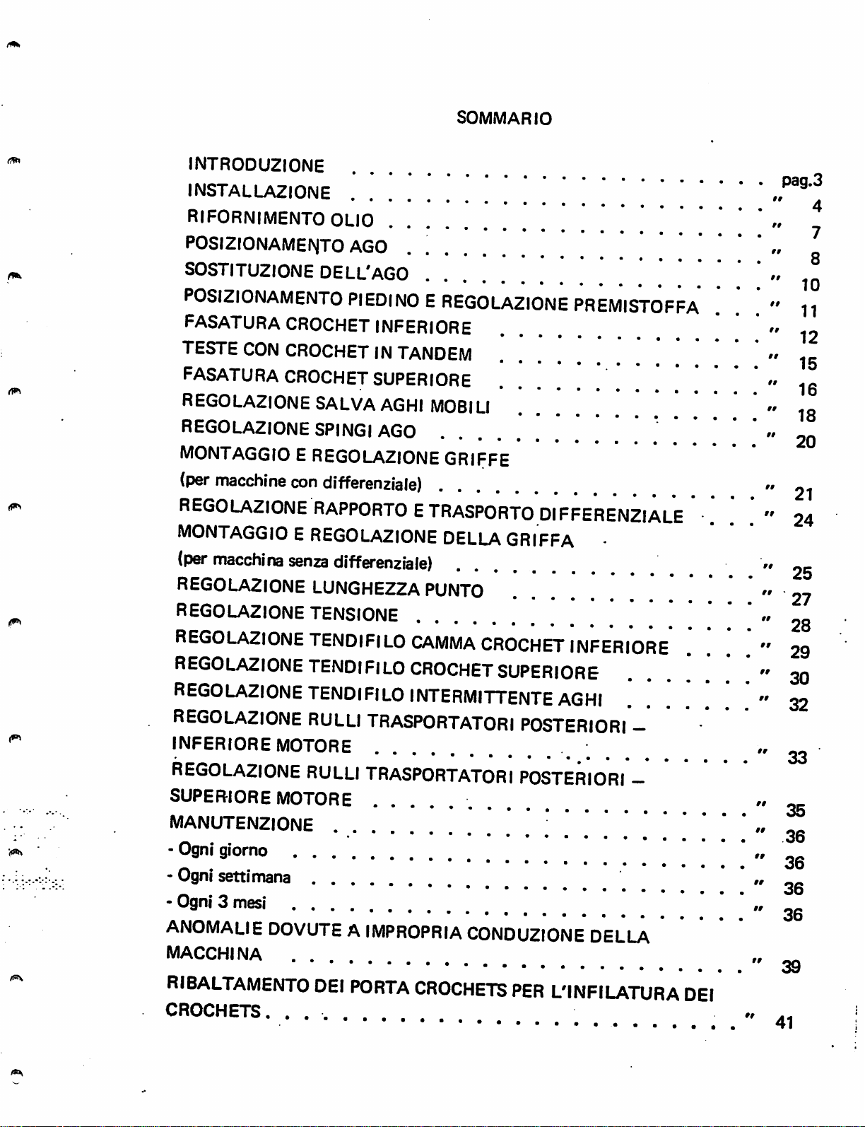
INTR0DU2I0NE
installazione
SOMMARIO
rifornimento
P0SI2I0NAMEIV|T0
S0STITU2I0NE
P0SI2I0NAMENT0
fasatura crochet
TESTE
fasatura
REG0LA2I0NE
REG0LA2I0NE
MONTAGGIOEREG0LA2I0NE
(per
REGOLA2IONERAPPORTOETRASPORTODIFFERENZIALE
MONTAGGIOEREG0LA2I0NE
(per
REG0LA2I0NE
REG0LA2I0NE
CON
CROCHETINTANDEM
CROCHET
macchine
macchina
OLIO
AGO
DELL'AGO
PIEDINOEREG0LA2I0NE
INFERIORE
SUPERIORE
SALVA
SPINGI
con
differenziale)
senza
differenziale)
LUNGHE22A
TENSIONE
AGHI
AGO
„ ^
. „
"
MOBILI
GRIFFE
DELLAGRIFFA
PUNTO
PREMISTOFFA
•
. .
' „ „
. . . "
"25
"28
"11
"12
•.
"21
iq
„
24
REG0LA2I0NETENDIFIL0CAMMA
REGOLAZIONETENDIFILO
CROCHET
REGOLAZIONETENDIFILOINTERMITTENTEAGHI
REGOLAZIONE
INFERIORE
REGOLAZIONE
SUPERIORE
RULLI
TRASPORTATORI
MOTORE
RULLI
MOTORE
TRASPORTATORI
MANUTENZIONE
-
Ogni
giorno
-
Ogni
settimana
_ . _ .
-
Ogni3mesi
ANOMALIE
macchina
RIBALTAMENTO
crochets.
DOVUTEAIMPROPRIA
DEI
PORTA
....
CROCHETS
CROCHET
INFERIORE
SUPERIORE
POSTERIORI
;
POSTERIORI
CONDUZIONE
PER
DELLA
L'INFILATURA
......
....
—
-
...
. . . "
DEI
"29
. "
"33
"35
"36
' "
" oc
» oc
„
«
30
32
36
36
06
gg
41
Page 3
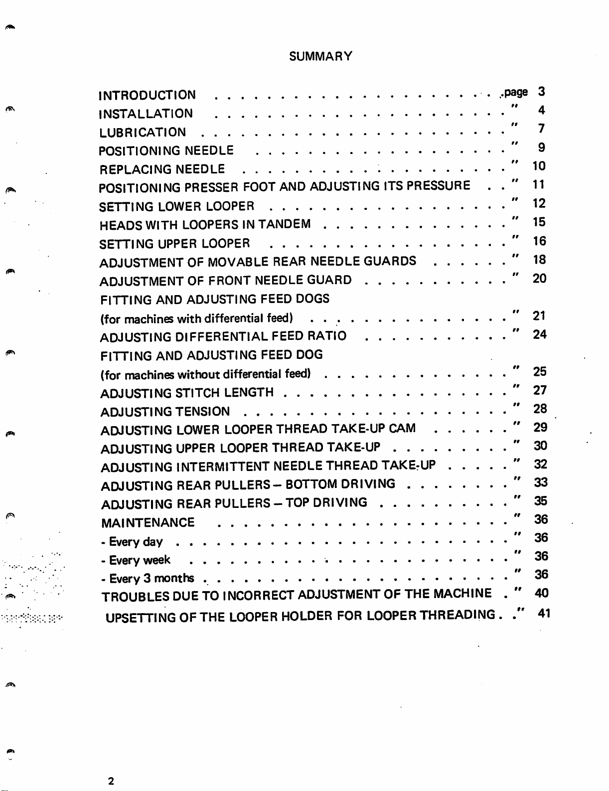
SUMMARY
INTRODUCTION
INSTALLATION
LUBRICATION
POSITIONING
REPLACING
NEEDLE
NEEDLE
POSITIONING PRESSER FOOT AND ADJUSTING ITS PRESSURE .
SETTING
HEADS
SETTING
ADJUSTMENT
ADJUSTMENT
FITTING
LOWER
WITH
UPPER
AND
LOOPER
LOOPERS
LOOPER
IN
TANDEM
OF MOVABLE REAR NEEDLE
OF
FRONT
ADJUSTING
NEEDLE
GUARD
FEED DOGS
GUARDS
(for machines with differential feed) .
ADJUSTING
FITTING
(for machines wit
ADJUSTING
ADJUSTING
ADJUSTING
ADJUSTING
ADJUSTING INTERMITTENT NEEDLE THREAD TAKErUP
DIFFERENTIAL
FEED
RATIO
AND ADJUSTING FEED DOG
tout
differential feed)
STITCH
TENSION
LENGTH
LOWER LOOPER THREAD TAKE-UP CAM
UPPER LOOPER THREAD TAKE-UP
....
page 3
" 4
" 7
" 9
"
10
' 11
'
12
'
15
'
16
'
18
'
20
" 21
"
24
25
27
28
29
30
32
ADJUSTING REAR PULLERS - BOTTOM DRIVING
ADJUSTING REAR
MAINTENANCE
- Every
day
PULLERS-TOP
DRIVING
- Every week
- Every 3
TROUBLES
UPSETTING
months
DUE
OF THE
TO
INCORRECT
LOOPER
ADJUSTMENT
HOLDER
FOR
OF THE
LOOPER
MACHINE
THREADING .
33
35
36
36
36
36
40
41
Page 4
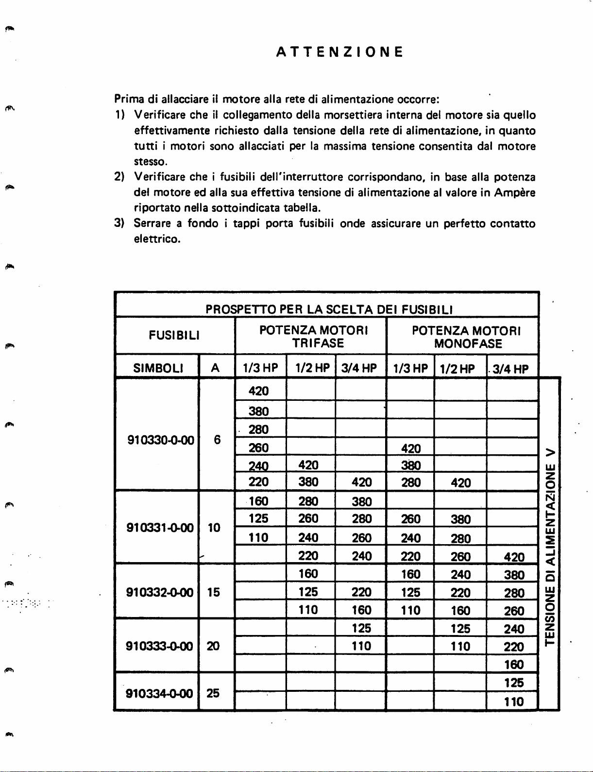
ATTENZIONE
Prima
di
allacciare
1) Verificare
effettivamente
tuttiimotori
stesso.
2) Verificare
del
motore
riportato
3) Serrare a
elettrico.
FUSIBILI
SIMBOLI
ii
motore
che
il collegamento della morsettiera interna del
richiesto
sono
che
i fusibili
ed
alia
sua
nella
sottoindicata
fondoitappi
PROSPETTO
A
alia
rate
dalla
allacciati
perlamassima
delTinterruttore
effettiva
tabella.
porta
PER
POTENZA
1/3
HP
di
alimentazione
tensione
tensione
fusibili
LA
SCELTA
MOTORI
TRIFASE
1/2
HP
della
retedialimentazione,
tensione
corrispondano,
di
alimentazione
onde
3/4
assicurare un
HP
DEI
occorre:
consentita
FUSIBILI
POTENZA
1/3
HP
motore
sia quello
in
dal
in base alia
al
valoreinAmpere
perfetto
MONOFASE
1/2
HP
potenza
contatto
MOTORI
.3/4
quanto
motore
•
HP
910330-0-00
910331-0-00
910332-(M)0
910333-000
10
15
20
420
380
280
6
260
240
220
160
125
110
420
380
280
260
240
220
160
125
110
420
380
280
260
240
220
160
125
110
420
380
280
260
240
220
160
125
110
420
380
280
260
240
220
160
125
110
420
380
280
260
240
220
160
>
UJ
z
o
N
<
H
Z
UJ
S
-j
o
UJ
2
O
(/)
z
UJ
1-
910334-0-00
25
125
110
Page 5
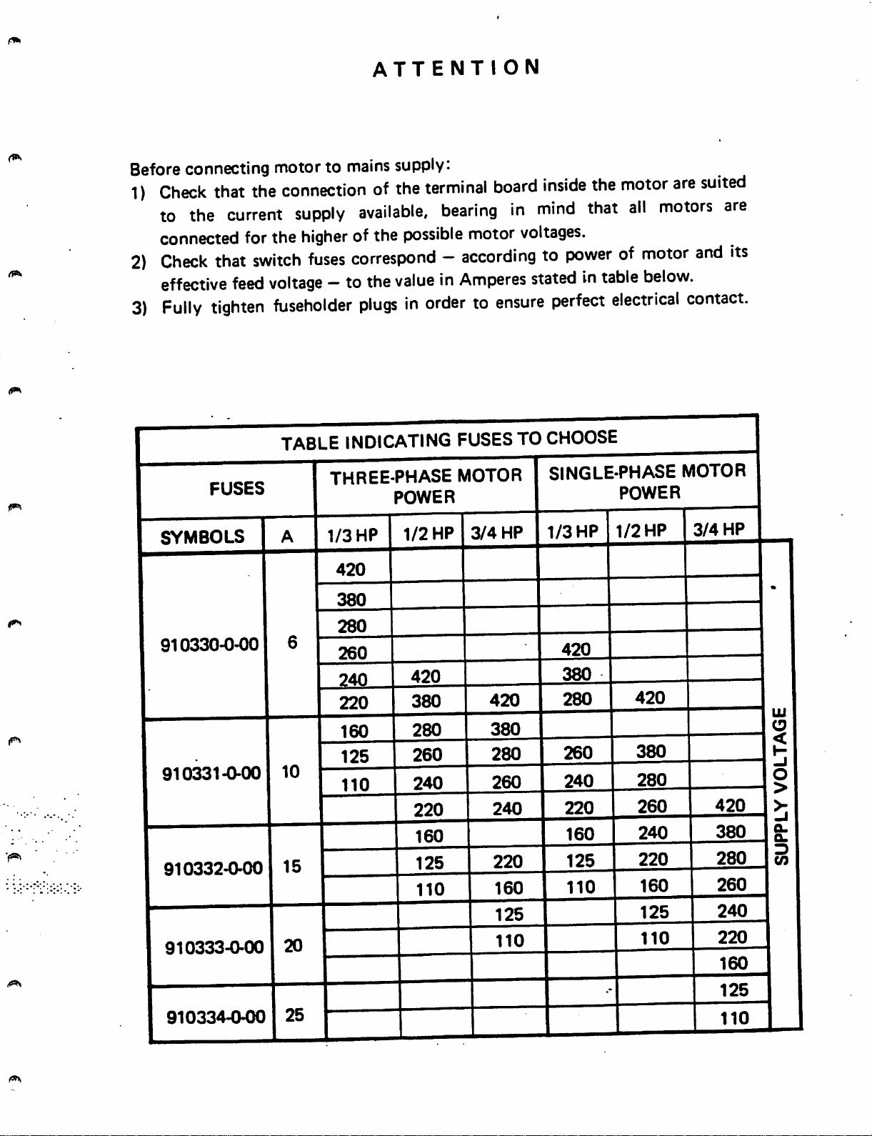
ATTENTION
Beforeconnecting motor to
1)
Check
to the
connected forthe
2)
Check
effective
3)
Fully
SYMBOLS
that
the
current
that
switch
feed
tighten
connectionofthe
supply
higher
fuses
voltage
- to
fuseholder
TABLE
1/3
mains
supply:
available,
of the
possible
terminal
bearing
motor
board
in
voltages.
inside
mind
the
that
motor
all
correspond-accordingtopowerofmotor
the
valueinAmperes
plugsinordertoensure
INDICATING
THREE-PHASE MOTOR
POWER
HP
420
1/2
FUSESTO
3/4
HP
statedintable
perfect
CHOOSE
SINGLE-PHASE MOTOR
HP
1/3
HP
below.
electrical
POWER
1/2
HP
are
suited
motors
and
contact.
3/4
are
its
HP
910330-0-00
910331-0-00
910332-0-00
910333-0-00
910334-0-00
Page 6
INTRODUZIONE
Abbiamo
puntoemanutenzione
LI
SERA"
convenientemente usare il nostro prodotto.
Queste
raccolto
che
riteniamo
macchine
nel
presente
delle
libretto
macchine
possano
giungonoaVoi
dopo
alcune
note
Rimoldi
esserVi
scrupolosi
utili
relative
Serie
per
megjio
controllierigorosi
permettonodigarantirneladurataeI'efficienza,maVi
dipendono
macchine,
consultare
contenute.
notevolmente
pertanto
attentamente
dall'usoedalla
prima
questo
manutenzione
deirimpiego,Viconsigliamo
fascicoloeseguire
* * *
con
all'installazione,
"BASE
CILINDRICA
conoscereepiu
collaudi
ricordiamo
che
saranno
nel
Vostro
cura
le
istruzioni
che
riservate
interesse
messa
che
queste
alle
in
esso
a
E
ci
di
INTRODUCTION
This
booklet
Rimoldi
themtobecome
Before
ensure
its
depend
thereforeinthe
instructions given in it.
contains
"CYLINDER
familiar
despatch,
the
durability
very
muchonhow
interestofthe
some
and
notesonthe
BED"
machine
with
which
the
machine
was
efficiency;itmust,
the
machineisoperated
ownertoread
installation,
shouldbeusefultoowners
and
derive
carefully
checked
operation
the
best
use
and
thoroughly
and
however,beremembered
and
maintained,
this
booklet
carefully
maintenance
and
should
from
it.
tested
that
anditis
and
follow
of
help
to
these
the
Page 7
INSTALLAZIONE
Per
rinstallazione
bancale), mediante cinghia di trasmisslone, procedere come segue:
1.
premere
piastradisostegno.
2.
piazzare
orecchiette
3. collegare
4.
collegareilvolantino
cinghia
(fig.
5.
registrarelatensione
da non consentire slittamenti, rha avendo cura di non tenderia eccessivamente
onde evitare sovraccarichi
durata della cinghia
mano al
cedimento
6. livellare la testa della macchina affinche la cinghia si trovi sul piano normale agli
assi
agire sui perni sostegno testa 3
gli
di trasmissione
3).
delle pulegge e
appositi
della
testa edilsuo
con
forzaiquattro
la
macchina
della
bacinella
il
tirante 1
centro
della cinghia, di
dadi.
del
collegamento
tamponi
sul
bancale,
sul
quattro
(fig.1)alia
della
sezione
della
stessa.
tratto
al
centro delle loro gole. Per I'operazione di livellamento,
leva
macchina
10x6
cinghia
sugli
Si ha la
indicato in fig. 3, si verifica una freccia, cioe un
10-15
(fig.
ammortizzatori
centrando
tamponi
alza
piedino
alia
(fig.2)secondoloschema
agendo
alberi delle pulegge e non compromettere la
mm.
1), avendo cura di bloccare successivamente
sullo
giusta
conilmotore
sugli
le
sedi
coniche
ammortizzatori 2
della
macchina
puleggia
tensione quando, premendo con la
snodo
del
attacco
motore
(gia
montato
appositi
perni
ricavate
(fig.
1).
con
I'apposita
di collegamento
motore,inmodo
sul
della
nelle
«
♦
♦
INSTALLATION
Installation of the machine headand connectionto the motor
the stand) by
1.
Press
Place
2.
on
the
3. Connectstay-rod1
4. Connect
(fig,
2) as
5.
Adjust
meansofdriving
the four shockabsorbersdown hard on the pinson the support plate.
the
machine on the stand, centeringthe conical
four
shock
machine
shown
the
insketch
belt
tisnsionbymoving
the belt cannot
overloading
correct
3,the
6.
Level
thus centered in their
belt
the machine head so that
pins3(fig.
the
when,
yields
1),
pulley
putting
making
absorbers
(fig.
handwheel
slip,
about
beltiscarriedoutasfollows:
2 (fig.
1) to machine presser foot lifter
(fig.
but
taking
shafts
manual
10-15
races.
suretolock
1).
to motor
pulley
3).
the
motor
care
and
shortening
pressureonthe
mm.
(3/8"-9/16").
the
belt is perpendicular to the pulleyaxesand
For
the
levelling
them
with
coupling
not to
again
make
the
lifeofthe
cisntre
operation, adjustthe headsupport
afterwards
housings
lever.
10x6
articulated
ofthe
(already
section
it
over-taut,
belt.
part
with
mounted on
of the sump
driving
lugs
belt
jointsothat
to
avoid
The
tension
indicatedinfig.
the
relative
nuts.
is
Page 8
7. montare, infine, il coperchio protezione cinghia in dotazione aila testa.
Per i primi 20 giorni impiegare la macchina a velocita rldotta, montando la cinghia
nella gola piccola della puleggia del motore, al fine di ottenere un perfetto rodaggio
che assicurera una piii lunga durata della macchina. In seguito spostare la cinghia
nella gola grande della puleggia motore e quindi portare la macchina ella velocita
massima
consentita.
7. Lastly, fix
For
the
first
the
small
raceofthe
longer life for
motor
pulley
on
20
and
the
belt
guard supplied
days
the
machine should be
motor
the
machine. Afterwards move
then
bring
pulley, in
the
machinetothe
PIAZZAMENTO
NORMAL
with
order
SETTING
the
machine.
runatreduced
to
run
it in
the
belt on
top
speed.
NORMALE
speed,
perfectly
to
the
with
the
belt
in
and
so
ensure
large race of the
a
Fig.1
5
Page 9
Fig. 2
I V
Fig.
3
Page 10
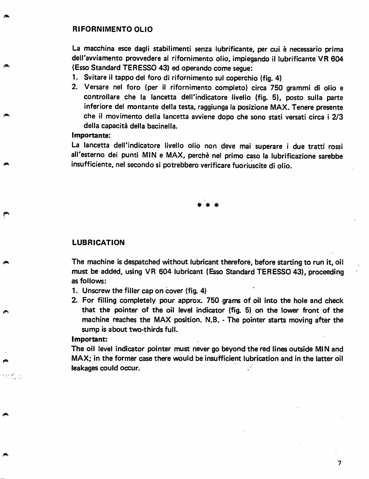
RIFORNIMENTO
OLIO
La macchina esce dagli stabilimenti senza lubrificante, per cui e necessario prima
11
deiravviamento provvedere ai rifornimento olio, impiegando
lubrificante VR 604
(EssoStandard TERESSO 43) ed operando come segue:
1. Svitare il tappo del foro di rifornimento sul coperchio
il
2. Versare nel foro (per
rifornimento completo) circa 750 grammi di olio e
(fig.
4)
controllare che la lancetta dell'lndicatore livello (fig. 5), posto sulla parte
inferiore del montante della testa, raggiunga la posizione MAX.Tenere presente
che
il movimento della lancetta avviene dopo
della
capacita
Importante:
La
lancetta dell'indicatore
della
all'esterno del punti
bacinella.
livello
MINeMAX,
olio non
perche
nel
deve
primo
che
sono stati versati circa i
mai
superare i due tratti
caso la lubrificazione sarebbe
2/3
rossi
insufficiente, nel secondo si potrebbero verificare fuoriuscite di olio.
* * *
LUBRICATION
The machine is despatched without lubricant therefore, before startingtorun it, oil
must
as
1. Unscrew
2.
important:
The
MAX;inthe
leakages
be added, using VR
follows:
the
filler
For
filling completely
that
the
pointer
machine reaches
sumpisabout
oil level
could
two-thirds
indicator
former
occur.
604
lubricant (Esso Standard TERESSO 43), proceeding
caponcover
pour
of
the
oil level indicator (fig. 5) on
the
MAX position. N.B. - The pointer
full.
pointer
case
there
(fig. 4)
approx.
must
would
760
never go
be
insufficient
grams
beyond
of
oil into
the
starts
the
red lines
lubrication
the
hole
lower
front
moving
outside
andinthe
and
after
MIN
latter
check
of
the
the
and
oil
Page 11
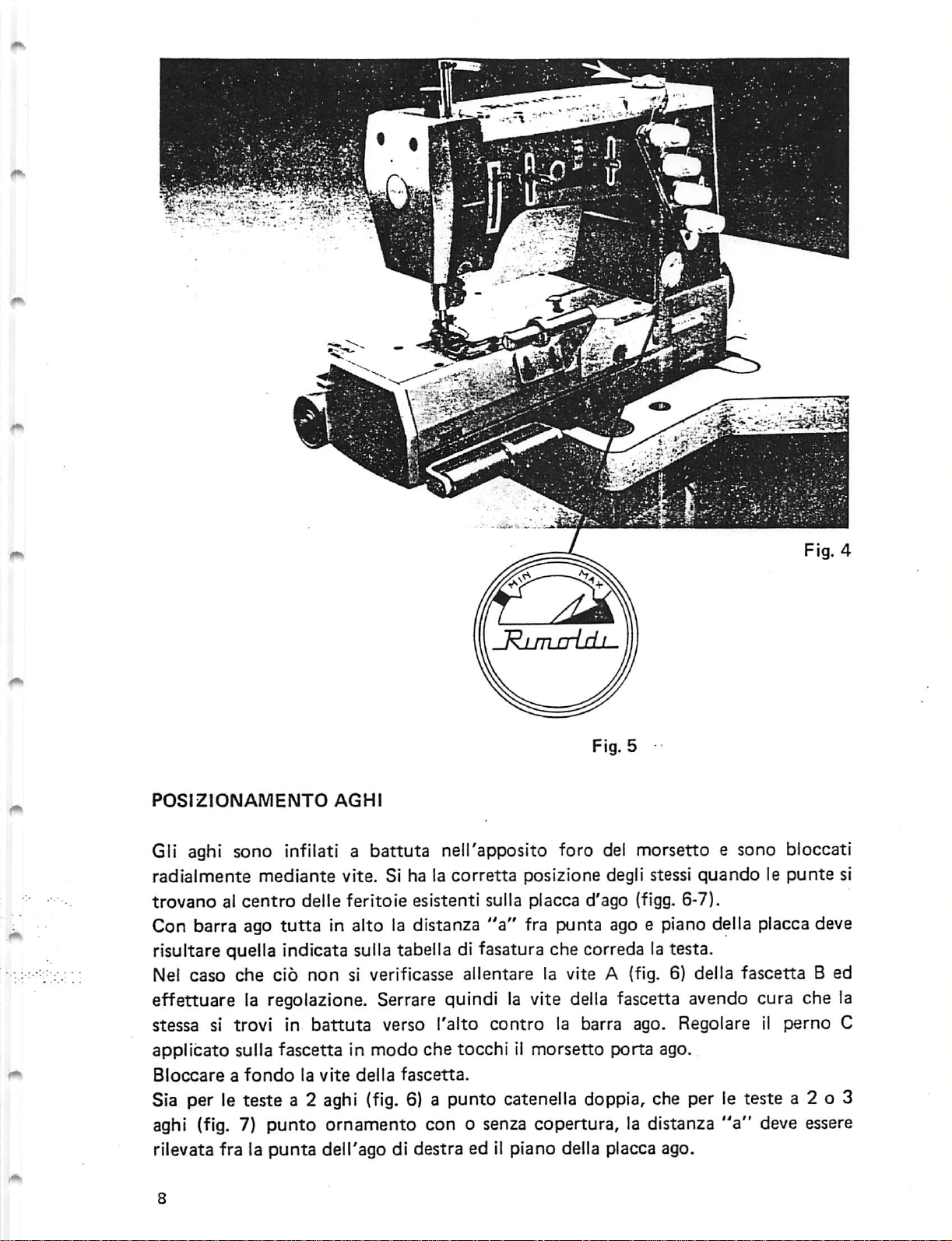
Fig. 5
£
POSIZIONAMENTO
AGHI
Gli aghi sono infilati a battuta nell'apposito foro del morsetto e sono bloccati
radialmente
trovanoalcentro
Con barra ago
mediante
delle
tutta
vite. Si ha la
feritoie
corretta
esistenti sulla placca d'ago (flgg. 6-7).
in alto la distanza
posizione degli stessi
"a"
fra punta ago e piano della placca deve
risultare quella indicata sulla tabella di fasatura che correda la testa.
Nel
caso
che
cio
non
si verificasse
allentare
la vite A (fig. 6} delta
effettuare la regolazione. Serrare quindi la vite della fascetta avendo cura che la
stessa si trovi in
applicato
Bloccareafondo
sulla
battuta
fascetta
la
vite
verso I'alto
in
modo
della
che
fascetta.
contro
tocchiilmorsetto
la barra ago. Regolare il
porta
Sia per le teste a 2 aghi (fig. 6) a punto catenella doppia, che per le teste a 2 o 3
aghi (fig. 7)
rilevata fra la
punto
punta
ornamento con o senza copertura, la distanza
delTago di
destraed11
piano
della placca ago.
quandolepunte
fascetta
ago.
"a"
si
B ed
perno
deve essere
C
Page 12
POSITIONING
NEEDLES
The needles are inserted into the hole of
The
needles
plate holes (figs. 6-7).
With
the
and
plate
the distance is incorrect
adjustment.
is
right
the
needle holder clamp. Fully tighten clamp collar screw.
For 2-needle double locked chainstitch machines
interlock
be measured between
are
correctly
needle
bar in its topmost
shouldbeas
Then
up
against
stitch
machines
positioned
indicatedinthe
slacken
tighten
the
the
needle
withorwithout
the
point of
screwA(fig.
clamp
bar.
the
the
clamp
when
position
collar
Adjust
their
the distance "a"
setting
table
6) of clamp collar B and
screw,
pinCon
top
spreader
right hand needle and the plate.
and
points
supplied
making
clamp
(fig.
are fixed by a screw.
areinthe
sure
collarsothat it
6) and for 2- or 3-needle
(fig.
center
between
with
that
the
7),
distance
needle
the
clamp
of
needle
point
machine.
make
collar
touches
"a"
If
the
must
Fig. 6
Fig.
7
y
Page 13
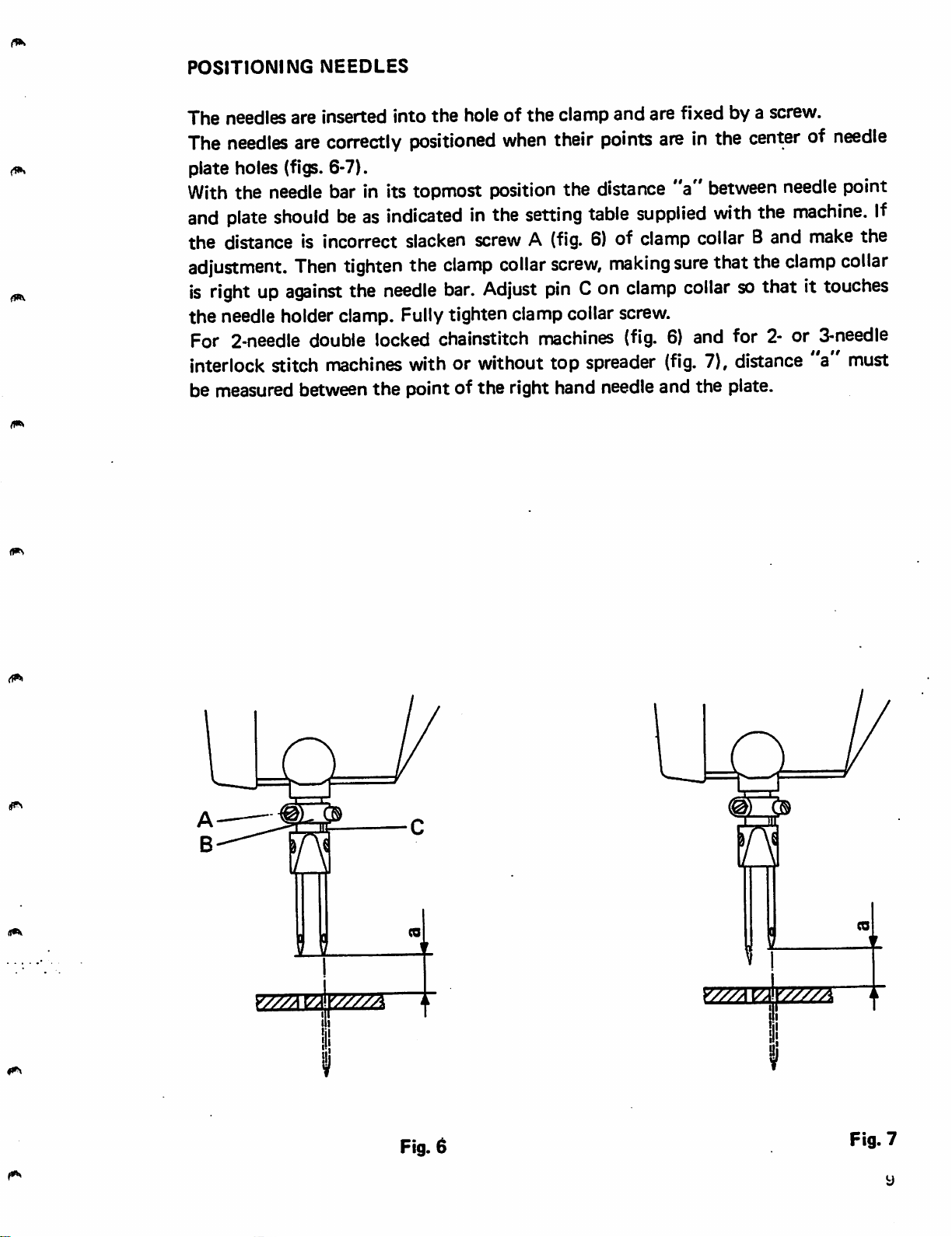
SOSTITUZIONE
AGO
Spegnere
assoiutamente
Ruotare
vite
serra
I'incavo
ii
motore
ferma.
normalmenteiivoiantino
ago
A (fig.
passaggio
ed assicurarsi,
9),
estrarre
crochet
deve essere
portando
I'ago e
premendo
sostituirlo
rivolto
la
verso
Servendosi della pinza in dotazione, accertarsi
Avvitare,
I'orientamento
REPLACING
Switch
pressing
Turn
fixing
Remember
the
inside
Using
the
end
not
to
senza
off
the
the
handwheel
screw
of
the
of
change
eccedere
dell'ago.
NEEDLE
the
motor
pedal.
A (fig.
that
the
the
machine.
pliers supplied with
the
hole. Tighten
the
orientationofthe
nel bloccaggio, la
and
make
to
bring
the
9|,
take
out
notch
that
the
the
vite
♦
« ♦
sure
that
the
needle
allows
machine,
the
bartoits
needle
the
looper
check
needle-fixing screw,
needle.
ii pedale,
barra
serra
ago
coniinuovo.
i'interno
che
I'ago appoggi sul
ago,
machine
topmost
and
replace
to
pass
that
the
without
che
la macchina sia
tutta
deila
in
alto.
Tenere
macchina.
Allentare
presente
fondo
avendo
has
must
curadinon
stopped
position.
it
with
be
completely
Slacken needle
the
turned
needle is pushed right
forcing, taking care
foro.
variare
new
one.
towards
ia
che
by
to
Fig. 9
10
Page 14
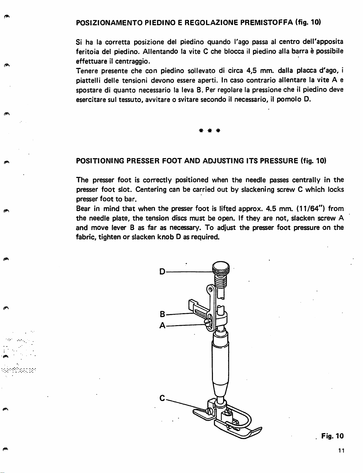
POSIZIONAMENTO PIEDINO E REGOLAZIONE PREMISTOFFA (fig. 10)
Si ha la
corretta
posizione del piedino quando Tago passa al
centro
dell'apposita
feritoia del piedino. Allentando la vite C che blocca il piedino alia barra e possibile
effettuareilcentraggio.
Tenere
piattelli delle tensioni
spostare di
esercitare
POSITIONING
The
presser
presser
Bear in mind
the
and
fabric, tightenorslacken
presente
che
quanto
sul
tessuto,
PRESSER
presser
foot
foot
is
foot
slot. Centering can be carried
to
bar.
that
needle
move lever B as
plate,
the
con
piedino sollevato di circa
devono
essere aperti. In caso
4,5
mm. dalla placca
contrario
allentare
d'ago,
la vite A e
necessario la leva B. Per regolare la pressione che il piedino deve
avvitare o svitare
secondo
* * *
il necessario, il
pomolo
D.
FOOT AND ADJUSTING ITS PRESSURE (fig. 10)
correctly
when
tension
far
the
knob
positioned
when
out
the
needle passes
centrally
by slackening screw C
which
presser foot is lifted approx. 4.5 mm. (11/64") from
discs
must
as necessary.
D as required.
be
open.Ifthey
To
adjust
the
are
presser
not,
foot
slacken
pressure
in
locks
screw
on
the
the
i
A
Fig.
10
11
Page 15

FASATURA
CROCHET
INFERIORE
Inserire fino a
sul piano di riferimento del gambo
Controllare con il foglio di fase (allegato alia macchina) che le misure riportate su di
esso corrispondano. Nel caso si dovessero
come
1. Per
2. Per ottenere la quota 0,05
3. Sulle teste a punto ornamento tipo
segue:
ottenerelaquota
L della fascetta M e agire sul tirante N della biella (fig. 13) sino ad ottenere la
quota
crochet
vite
G (fig. 15) e registrare
durante la sua discesa, deve coincidere con il punto di convergenza delle due
linee che formanoilprofile inferiore della lama del crochet (fig. 16)
Sulle teste 174 a 2
la discesa deve
4. Gli aghi nella lore discesa devono entrare in contatto con il dorse della lama del
crochet
prolungamento ideale della tacca di riferimento D (fig. 15), incisa sull'albero
principale,
battutailcrochet
prescritta
e I'incavo dell'ago
dalla
aghi,
essere
flettendo. Per
risuiti
allineataconilfore del rispettivo crochet
tangentealdiametro
A nelTapposita sede del
con
la vite B (fig. 11).
'b'
fig. 12
tabella
portareilcrochet
di
fase.
(fig.
14) che rappresenta la distanza fra la punta del
durante
facendo
la sua corsa da
ruotare
effettuare
I'albero H.
171
e 173, la punta dell'ago interne,
alcune registrazioni
tutto
destra
a punto catenella doppia, lacruna di
ottenere
questa condizione e necessario che il
esterno
della
vite
porta
crochet
a destra, allentare la vite
a sinistra allentare la
ogni
(fig.
E.
e bloccarlo
operate
ago
durante
17).
* * *
SETTING
Fit
looperAright
screw
Check
the
machine. If adjustments must be made, proceed as follows:
1. To
of
distance indicated in setting table is obtained.
2. To obtain distance0.05
point
slacken screw G
3.
On
the
convergence
On 174
during
(fig.
4. In their downward stroke the needles must come into contact with the back of
the
extending from reference notch D (fig. 15) on main shaft would havetobeata
tangent
LOWER
B (fig. 11).
thatthe
obtain
sleeve
distance
collar
of the
171
and
downward
2-needle
the
downward
17).
looper
to
blade,
the
LOOPER
downinits
measurements
"b"
(fig.
Mand
adjust
mm.
looper
173
and the
(fig.
15) and adjust by turning shaft H.
interlock
movement
of the
kines
forming
double
stroke
bending
external
diameter
seat
in the
looper
correspondtothose
12)
bring
stay-rod N of
(fig.
needle
stitch
machines
of the
the
locked
chainstitch
must
slightly.
of
looper
14) which represents the distancebetween the
notch
the
needle,
lower
outlineof the looper
beinline
To obtain
screw
E.
holder
inthe
fully
connecting
during
its
point
must
with
coincide
machines
the
this
and
fix
it in
position
setting
to the
stroke
ofthe
chart
right,
rod
inside
with
supplied
slacken
(fig.
13)
from
right
needle,
the point of
blade
the eye of each needle
hole
ofthe
condition
relative
an
imaginary
screw
until
to
during
(fig.
looper
with
with
the
left,
16).
line
L
12
Page 16

(1^
Attenzione - in caso di sbioccaggio delle viti E ed F (fig. 15), per ottenere le
condizioni di cui sopra, la faccia esterna deii'eccentrico C deve sfiorare
{'estremita
della
tacca
di
riferimento
D.
* * *
Attention:
conditions
reference
If screws E
the
external plane
notch
D.
Fig. 11
and
F (fig. 15) are
of
undone,inordertoobtain
eccentric C
must
just graze
the
the
above
extremity
of
Fig.
13
t
(1^
Fig.
Fig.
12
14
13
Page 17

I
Fig.
15
Fig.
16
14
i
*5
Fig.
§
17
Page 18

TESTE
CON
CROCHET
IN
TANDEM
Ambedueicrochet,
crochet
II
qualeemontato.
La biella B
alternativo.
Per
capitolo
relative
HEADS
The
looper
laterale delle
gruppo porta crochet A riceveilmoto oscillatorio traversaie dal contralbero sul
trasmette
quanto
movement
on
riguarda la fasatura del crochet, operate secondo le istruzioni nel
"Teste
Tabelle
WITH
double
assembly A receives
which
to
it is
looper
mounted.
holdersCand
For setting the loopers, followthe instructions
lower looper" and keepto the setting values
nel
testeapunto
con
crochet
di
fasatura.
LOOPERS
of
both
locked
the
Connecting
lore
movimento
inoltre
laterale",
IN
TANDEM
the
loopers
chainstitch
catenella
ai
descrivono
porta
describes
crochet
mentre
* * ^
machines
doppia,
per
the
fitted
tranverse rocking movement
rodBtransmits
D.
given
given
la stessa
chenesono
C e D il
i valori di fase
same
elliptic
with
alternate
traiettoria
moto
trajectory
this.
from
the
longitudinal
elittica
provyiste.
longitudinale
attenersi
The
looper
countershaft
as
the
movement
Inthe chapter headed "Setting
in the relative Setting Tables.
del
alle
side
holder
on
crochet
in
Tandem
LoopersinTandem
cxs:
15
Page 19

FASATURE
CROCHET
SUPERIORE
Controllare, con il foglio fase allegato ad ogni macchina che le misure
corrlspondano.
Nel
casesidovessero
1. (quota 'e'). Diminuendo la quota
della
corsa
del
Per modificare la
biella
2. (quota
crochet.
B.
'f').
crochet,
Per
effettuare
quota
ottenere
alcune
aumentandolaquota
'h'
registrazioni
'h',
riportata in fig.
operare
'h'sidiminuisce.
come
21,
si ottiene I'aumento
segue:
allentare la vite A (fig. 21) e spostare la testa di
la quota'fallentare la vite C (fig. 19) e ruotare il porta
'e'
'f
e 'g'
3. (quota 'g'). Per ottenere la quota 'g' allentare la vite D (fig. 20) e ruotare il
crochet.
porta
SETTING
Far
crochet
UPPER
attenzione
E (fig.
LOOPER
22).
che
I'anello
«
di
fermo
♦
F sia
sempreabattuta
contro
il
Check with setting chart supplied with each machine that distances "e",
"g"
are correct.
If
adjustments
1. (distance
increased; by increasing distance
slacken screvy A (fig. 21) and shift big endofconnecting rod B.
2. (distance
holder.
3. (distance "g") To obtain distance "g",
Make sure
are necessary, proceed as follows:
"e")
By reducing distance
"h",
"h"
"f")
To obtain distance
"fslacken
slacken
that
locking ring F is always close
shown in fig.21,
the
looper stroke is
it is reduced. To modify distance
screw C (fig. 19) and
screwD(fig.
up
against looper holder E (fig. 22).
20)
turn
andturn looper.
"f"
looper
and
"h"
Fig.
18
16
Fig.
19
Page 20

Fig.
20
Fig.
22
Fig. 21
•|7
Page 21

REGOLAZIONE
Le
teste
serie
Detto
punto
riportate
1. Regolazione su
salva
sara
in fig.
ago
Ruotareilvolantino fino a portare la griffa tutta in avanti
Allentare il
SALVA
171,173e174
e montato
indispensabile
23,
procedendo come segue:
porta
dado
griffa senza differenziale
A e far scorrere il salva ago B (fig. 24) fino a trovare le
AGHI
sul
MOBILl
sono
portagriffa;
posizionare
dotate
di salva ago mobile.
percidadogni
il
salva
ago
variazione di
onde ottenere
(verso
lunghezza
le
condizioni
Toperatrice).
condizioni della fig. 23. Bloccareildado A e controllare le condizioni sopra
descritte.
2. Regolazionesu porta griffa differenziale (fig.25)
Le operazioni sono le stesse del paragrafo 1; in questo caso pero e necessario
fare
attenzione
tenendo
piano
di quelle della griffa differenziale.
presente
affinche
che
non
venga spostata verticalmente la griffa principale,
le cuspidi del denti di questa devono essere sullo stesso
del
«
♦
♦
ADJUSTMENT
Class
171,173
This needle guard is mounted on
OF
and
MOVABLE
174
heads are
REAR
fitted
the
NEEDLE
with movable rear needle guard.
GUARDS
feed dog holder; therefore every time the
stitch length is altered it is essential to position the rear needle guard in order to
obtain
1.
2. Adjustment on differential feed dog holder
the
conditions
Adjustment
on
Turn handwheel until
shown
feed dog holder
in fig.
the
feed dog is in its most forward position (towards the
23,
proceeding as follows:
without
differential
operator). Slacken nut A and slide rear needle guard B
positioned as shown in
above.
The operations are
taken
not
to
move
the
the
of the feed dog teeth must be on the same
dog.
fig.
23. Lock nut A and check conditions described
(fig.
25)
sameas in paragraph 1; in this case, though, care must be
main feed
dog
vertically, bearing in
level
as those of the differential feed
(fig.
mind
24) until it is
that
the
points
18
Page 22

©
Fig.
23
a
Fig.
-A
-B
24
Fig.
25
19
Page 23

REGOLAZIONE
SPIiMGl
AGO
Tutte
supporto
le teste serie 171 e 173 sono dotate di spingi ago
calettato
sul
porta
crochet
(fig. 26).
montato
su apposite
Le condizioni di posizionamento esatto sono quelleche si vedono in fig. 27. Infatti
la posizione deila punta del crochet rispetto alTago
interne,
quando11crochet
muove da destra verso sinistra, coincide con la posizione del salva ago mobile che
dovra trovarsi circa da 0,1 a 0,15 mm dall'ago interne con lo spigolo alia stessa
altezza della parte superiore della cruna delKago.
Per ottenere tali condizioni si sbloccano le viti A e B (fig. 26). Con I'allentamento
della vite A si regola lo spingi ago in verticale rispetto all'altezza della cruna, mentre
con I'allentamento della vite Bsi
ADJUSTMENT
OF
FRONT
regola
NEEDLE
I'accostamento dello spingi ago
* * *
GUARD
agli
aghi.
All Class 171 and 173 heads are fitted with front needle guard mounted on special
keyed
The exact positionings are those shown in
in relation
coincides with
approximately
height as
To obtain this setting, slacken screws A and B (fig. 26). With screw A slackened
bracket
to
the
on
looper holder (fig. 26).
the
internal needle, when the looper moves from right to left,
the
position of the
0.1-0.15
top
partofthe
mm.
needle eye.
from
the
fig.
movable
internal
27. The position of the looper point
rear needle guard that must be
needle
with
the
corner
at
the
same
the
front needle guard can be adjusted vertically in relation to the needle eye, while
with screw B slackened
can
be
adjusted.
the
distance between the front needle guard and
the
needles
si
@
20
Fig.
26
Page 24

0,1+0.15
Fig.
27
MONTAGGIO E REGOLAZIONE
differenziaie)
Montaggio griffe su
• Montare
porta
con
griffa B.
porta
griffe
la vita C la griffa
anteriore
GRIFFE
(fig. 28) (per macchine
differenziaie A neila sua sede deila siitta
con
• Montare la griffa principale D senza bloccaria a fondo sulla squadretta porta griffa
E
tramite
- Collocare it
griffa D
FITTING AND ADJUSTING FEED DOGS (fig. 28) (for machines
feed)
le
con
due
tutto
la A.
viti
H.
sul braccio
porta
griffa ed allineare approssimativamente la
* *
*.
with
differential
Assembling feed dogs on feed dog holders
- Mount front differential feed dog A in its seat on slide
means
- Mount
without
• Set it all on the feed dog holder arm and
feed
of
screw
main
C.
feed dog Don feed dog holder bracket Eby
screwingitdown completely.
dog
A.
align
feed dog D approximately with
of
feed dog holder B by
means
of two screws H,
21
Page 25

Centratura
-
Allentare
•
Montare
placca
•
Bloccare
-
Allineare
griffe
le
due
viti
G.
la placca d'ago e centrare in senso laterale la griffa A nelle feritoie della
d'ago
spostando
le
viti
G.
perfettamente
rintero
- Togliere la placca d'ago.
bloccaggio a
•
Rimontare
-
Rimontare
scorrere
-
Se
le griffe toccassero la placca
della
forcella
•
Ruotare
placca
•
Bloccare
d'ago
fondo
della griffa D sulla
di nuovo la squadretta E e bloccare leggermente
la placca
le griffe neila
Q.
d'agoe,facendo
placca
il gruppo F ed eseguire la centratura delle griffe
leggermente la
la griffa
Smontare
d'ago.
vite
P.
gruppo differenziaie F.
principale
D.
la
squadretta
squadrettaEtramite
ruotareiivoiantino
d'ago
sul
fondo
delle
porta
feritoie,
griffa E ed eseguire il
le viti H.
con
nel
la vite
senso
0.
di marcia,
allentarelavite
rispetto
alle feritoie della
far
P
« ♦
♦
Centering
•
Slacken
•
Mount
moving
-
Tighten
- Align main feed
• Remove the needle plate.
the
feed
dogs
the
two
screws
needle plate
the
whole differential assembly F.
G.
and
center feed dog A laterally in
screws G
dog
D accurately
Disassemble
the
needle plate slot,
feed dog holder bracket E and fix feed dog
D firmly on bracket Ebymeansofscrews H.
•
Re-mount
- Re-mount needle plate and, turning handwheel in
feed
dog
bracketEand
runinneedle
fasten
plate.
tightly
with
screw
0.
the
normal direction, make
- If the feed dog touches the bottom of the needle plate slot, slacken screw P of
fork
Q.
. •
•
Turn
- Lightly fasten screw P.
assembly F
and
center
feed dog in relationtoneedle plate slot.
22
Page 26

H E D A
3—c
Fig.
28
23
Page 27

REGOLAZIONE RAPPORTO TRASPORTO DIFFERENZIALE (fig. 29)
AllentareildadoVcon
averelaposizione
ADJUSTING
Slacken
nut
positionisobtained.
desiderata.
DIFFERENTIAL
V using special
Then
I'apposita chiave e spostare la leva L nel
Bloccare
FEED
spanner
tighten
quindiildado
* * *
RATIO (fig. 29)
and
move lever L in
nut
V.
V.
sector
settore
T until
T fino ad
the
desired
24
Fig.
29
Page 28

MONTAGGtO E REGOLAZIONE DELLA
GRIFFA
(per macchine senza
differenziale) (fig. 30)
Montaggio griffa su
porta
griffa
• Montare la griffa A neii'apposita sede della squadretta porta griffa B e inserire la
vite
C.
• Bloccare la
Centratura
-
Allentare
•
Montare
placca d'ago spostando I'intero gruppo F.
•
Bloccare
sulla
placca
- Se la griffa toccasse il
della
forcella
-
RuotareilgruppoFed
placca
- Bloccare leggermente la vite G.
Allineamento
-
AllentareildadoDedilgrano
• Allineare la cresta dei
I'eccentrico
squadrettaBconildado
della
griffa
le
due
viti
E.
la placca d'ago e
le viti E
d'ago.
d'ago
far
H.
centrare
ruotareilvolantino
fondo
eseguirelacentratura
delle feritoie della placca d'ago, allentare la vite G
griffa rispetto al piano placca d'ago.
L.
M.
Serrareilgrano
denti
rispetto
L e
bloccareildado
D e la griffa A
con
la vite C.
in senso laterale la griffa A nelle
nel
sensodimarciaefar
della griffa
al piano della placca
rispetto
D.
scorrerelagriffa
alle
d'ago
feritoie
feritoie
manovrando
della
della
* * *
FITTING
AND
ADJUSTING
FEED
DOG
(for
machines
without
differential
feed)
(fig. 30)
Assembling feed
• Mount feed dog A in
screw
- Lock
-Centering
•
Slacken
C.
bracketBwith
the
the
dogonfeed
feed
dog
two
screws
dog
the
special seat on feed dog holder bracket B and insert
nutDand
E.
holder
feed dog A
with
screw
C.
• Mount needle plate and center feed dog A laterally in needle plate slot, moving
the
whole
- Tighten
needle
- If the
fork
-
Turn
assembly F.
screwsE,turn
plate.
feed
dog
H.
touches the bottom of the
handwheel
in
normal
direction and
needle
plate
slot,
make
slacken
assembly F and center feed dog in relationtoneedle plate slot.
feed dog run in
screw
G of
• Lightly fasten screw G.
Alignment of feed dogtoneedle plate surface
• Slacken
-
Align
eccentric
- Tighten grub screw Land
nut
D and grub screw L.
the peak of the teeth in relation to the needle plate surface by
M.
nut
D.
moving
25
Page 29

Regolaztoneinaltezza
•
Regoiareinaitezza
la griffa in
modo
che
nella massima
alzatalacresta
dei
sporga dal piano della placca, di mm. 1,2. Fissare quindi la griffa mediante la vite
C.
* * *
denti
Adjustment
- Adjust
peaks of
•
Then
fasten feed
in height
the
feed dog in height so that, when it is raised
the
teeth
jut
dog
out
1.2 mra from
with
screw C.
the
needle plate surface.
to
the
maximum, the
26
Fig.
30
Page 30

REGOLAZIONE LUNGHEZZA PUNTO (fig. 31)
La lunghezza del punto pud essere variata mediante il volantino B (fig. 31) che a
questo
Premereiiperno
stesso possa inserirsi nella
volantino
rindicatore
ADJUSTING STITCH LENGTH (fig. 31)
The
there
To
Press pin A and
of
the
scopoegraduate
B
fincheilnumero
D,
stitch
make
regulator
desired
length is varied
is a
graduated
the
variation, proceed as follows:
C,
stitch
esternamente.
A e far
rilasciare
quindiilperno
by
scale.
turn
handwheel B until
next
forcibly
length coincides
Per la variazione
ruotare11volantino B fino a
tacca
meansofthe
turn
del regolatore C, quindi
corrispondente
A.
* * *
alia
handwheel B, on
the
extremityofthe
handwheel B
with
mark D,
then
lunghezza
until
the
release pin A.
procedere
che
I'estremita
ruotare
desiderata
the
outer
pin fits
number
come
segue:
del
con
forza
coincida
perno
partofwhich
into
the
notch
corresponding
con
il
to
Fig. 31
27
Page 31

REGOLAZIONE
TENSIONE
It filo viene
nell'interno
necessario
tensione
Nella maggior
premuto
del
regolarelapressione
stessa.
parte
fra i due dischi A (fig. 32) delta tensione, dalla molla situata
pomolo,
dei casi, la
quindl
delta molla,
tensione
per
avere la giusta
avvitandoosvitandoilpomolo
del filo per
formazione
crochet
del
inferiore viene
punto
B delta
tenuta
lenta e la regolazione si effettua mediante la tensioncina applicata sulla camma
tendifilo.
* * m
ADJUSTING
The
thread is held between
inside
the
regulate
In most cases,
knob. So,
the
pressure of
TENSION
the
tensionofthe
the
two discs A (fig. 32) of
to
obtain
the
spring by screwingorunscrewing knob B of
the
correct stitch formation, it is necessary
lower -looper thread is
the
kept
tension by
slack and
the
spring
the
tension.
adjustment
to
made by means of the small tension on the thread tensioning cam.
e
is
mm
^rMMniirnr^
Fig.
32
Page 32

REGOLAZIONE TENDIFILO
173)
I
due
levetta
dischi della
fermafilo
camma
A e I'astina B (fig.
GAMMA
tendifilo
debbono
33).
CROCHET INFERIORE (per testa 171 e
essere
perfettamente
centrati
con
Per eseguire detta regoiazione ailentare la vite C deiranello D e le viti E sul mezzo
della
fissarii
camma
treva
escursiene
Tenere ineltre presents
tenders
Accertarsi della
camma;
entrambi
far scorrere assialmente camma ed anello
nella
deve fare rasamento
riscentre
il
sue
radiale
file.
nella
della
feriteia
corretta
sull'albero
corretta
camma
che
regoiazione
centre
G del
stessa.
posizione
Tanelle D.
mezzo
tenendo
presents
L'anelleDmediants
della
camma
H,
che
11
la spina F,
cestituisce
mezzo
quande il crochet inizia la sua cersa verse destra deve
effettuande
* * *
alcune
prove di
cucitura.
principale e
della
che
il
limits
la
di
ADJUSTING
heads)
The
two
thread
lever A
To
cam
mind
and
make
and
that
LOWER
take-up cam discs must be perfectly
rod
B (fig.
the
adjustment,
ring axially on
the
cam
hub
LOOPER
33).
slacken
shaft
must
screwCof
and
be right
THREAD
fix
them
up
against ring D.
TAKE-UP
centered
ring D
and
bothinthe
CAM
with
screws E
correct
(for
171
thread
on
cam
position,
and
173
retaining
hub.
Slide
bearing in
Ring D, through pin F that fits in slot G of hub of cam H,establishes the limit of
radial
Also bear in
tension
Check
movement
mind
its
thread.
that
adjustment
of
said
cara
that
when
the
is correct by carrying
looper
starts
out
its
some
stroke
test
towards
seams.
the
G C
right, it
must
Fig.
33
Page 33

REGOLAZIONE
TENDIFILO
CROCHET
SUPERIORE
Al governo del filo del crochet di copertura (fig. 34) sulle teste 173 e predisposta
un'asttna
Le
condizioni
verso
quando
filo di
L'astina
allentando
La
camma
regolata
tirafilo
ottime
sinistra,
la
I'astinaAtiene
punta
copertura
A si
le viti D (fig.
E (fig.
verticalmente
A
montata
di fase si
suiranello
hanno
il filo in
delTago sinistro e ben
come
puo
rappresentato
regolare assialmente
34).
35)
concorre
ed
orientate
alia formazione del triangolo del filo.
B.
quando
tensione.
penetrato
in fig.
35.
con
crochet
L'azione
nel
allentando
secondolanecessita.
* * *
superiore
dell'astinaAdeve
triangolo
la
vite
di filo
C
ed
spostato
tutto
cessare
formato
angolarmente
Puo
essere
dal
ADJUSTING
To
control
thread
tensioner
Optimum
when
point
the
Rod A
screws
the
of
cover
can
D (fig.
UPPER
the
thread
setting
top
looper
the
left hand needle has penetrated well into
thread,asshown
be
adjusted
LOOPER
of
cover looper (fig. 34) on Class
rodAmounted
conditions
is fully
are obtained when
to
in fig. 35.
axially by slackening screw C
THREAD
34).
Cam E (fig. 35) helps in forming
and
positioned directionally as required.
on
the
TAKE-UP
173
machines
ring B.
rod
A holds
left.
The
action
of
rodAmust
the
and
the
thread triangle. It can be adjusted vertically
the
thread
angularly
thread
triangle
stop
formed
by
slackening
there
tensioned
when
is a
the
by
30
Page 34

Page 35

REGOLAZIONE
Le
macchine
tendifiio a corsa regolabile
TENDIFILO
serie
171
INTERMITTENTE
e
173
sono
dotate
coniiquaie si possono
di
tendifilo
AGHI
ottenere
intermittente.
cuciture
Essoeun
piu o meno
elastiche, per aumentare oppure per diminuire11cappio degii aghi.
La regolazione delta sua corsa si ottiene (dopo aver tolto it coperchio del braccio)
allentando.ildado A (fig. 36) e spostando versoilbassoilperno B quando si vuole
aumentarelacorsa,overso
Talto
quandosivuole
diminuirla.
Una targhetta C millimetrata posta sul davanti del braccio permette di valutare
Tentita
delta
corsa
del
tendifilo
D.
ADJUSTING
Class 171
adjustable
be
obtained,
Its
stroke
nut
A (fig. 36)
upwards
INTERMITTENT
and
173
machines are
stroke
thread
take-up
by increasingordecreasing
can
be adjusted (after having removed machine
and
moving pin B downwards in
to
decrease
it.
NEEDLE
fitted
with which seams having
Plate C calibrated in millimetres, on
of
the
valueofthread
take-up
D stroke.
the
THREAD
with
the
sizeofthe
front
TAKE-UP
intermittent
order
thread
moreorless
needle
thread
arm
to
increase
take-up.
cover)
elasticity
loops.
by
slackening
the
stroke
It is an
can
of machine arm, gives an indication
or
Fig.
36
Page 36

REGOLAZIONE
MOTORE (fig. 37)
RULLI
TRASPORTATORI
POSTERIORI
-
INFERIORE
I ruili
trasportatori
sono
comandati
dalto stesso
organo
che
comandailtrasporto
griffa. Variando, quiadi,iltrasporto si ottiene contemporaneamente la variazione
della
corsa
del
rullo
motore
inferiore.
La regolazione della corsa dei rulli trasportatori si ottiene ailentandoildado D e
facendo
centro
scorrere il perno E nell'asola dei
d'oscillazionesidiminuiscelacorsa,
* * *
settore
avvicinandolosiaumenta.
F.
Allontanandoilperno
dal
a
ADJUSTING
The
puller rollers are controlled by
the
feedisaltered
roller.
The
run
REAR PULLERS - BOTTOM DRIVING (fig.
there
of
the
feed rollers is adjusted by slackening
of sector F. By moving
and
by
moving it nearer
37)
the
same part
is a
simultaneous
the
pin away from the rocker centre the run is decreased,
the
run is increased.
variationinthe
that
controls feed dog feed. When
run
of
the
bottom
nutDand
sliding pin E in
driving
slot
33
Page 37

0
0
p
34
Fig.
37
Page 38

REGOLAZIONE
MOTORE (fig. 38)
RULLl
TRASPORTATORI
POSTERIORI
-
SUPERIORE
I rulli
da
trasporto
trasportatori
posteriori,
quandoemotore
il rullo superiore,
un eccentrico posto sull'estremita destra dell'albero principale
a griffa.
sono
comandati
indipendente
dal
La regolazione della corsa dei rulli si ottiene dopo aver ruotatoilcoperchietto A
posto
scorrereilperno
in
alto
sulla
C nella
parte
cava
destra
D del
della
settore
macchina,
E.
allentandoildado
B e
facendo
Allontanandoilperno dal centro di oscillazione della leva E si diminuisce la corsa,
avvicinandolo
si
aumenta.
«
♦
♦
ADJUSTING REAR PULLERS - TOP DRIVING (fig. 38)
When
eccentric situated on
dog
Adjustment of the run of the rollers is made after havingrotated cover A on the
the
feed.
top
roller is driving,
the
extreme right of
the
rear puller feed rollers are controlled by an
the
main shaft Independent of
the
feed
top
right hand part of the machine, by slackening nut B and sliding pin C in slot D of
sector
By moving
by
E.
the
pin away from
bringing it nearer
the
run
is increased.
the
rocker
centreoflever E
the
run is decreased
and
mnnn/iij
Fig.
38
Page 39

MANUTENZIONE
Sono
per
Ogni
Pulire
punto.
Controllare
Ogni
Smontare
Ogni3mesi
Sostituire
qui di seguito elencate le operazioni periodiche di
mantenere
giorno
tutti
•
la
macchina
sempreinperfetta
efficienza.
gli organi della macchina relativi a!
il
livello
olio.
trasporto
settimana
la placca ago e pulire griffe, crochet e trasporto.
I'olio e pulire il filtro principale.
manutenzione
e alia
formazione
necessarie
del
Per scaricare I'olio dalla bacinella svitareiltappo di scarico B (fig. 39).
Per accedere al filtro svitare le due viti D che fissano il
tappo
E alia bacinella.
Aiutandosi eventualmente con una chiave del tipo illustrato in figure, avvitata nel
foro
centrale
del
tappo,
sfilare lo stesso -
completo
di filtro - dalla bacinella.
Togliereilfiltro del tappo, pulirlo con benzine e soffiarlo con aria a bassa pressione.
MAINTENANCE
Listed
to
Everyday
Clean all
Every
Remove
Every 3
Replace
To
To
Using a
hole
Take
compressed
below
keep
the
machineinperfect
the
week
needle
months
the
empty
the
reach filter,
spannerofthe
of
plug, remove plug, complete with filter, from sump.
filter
air.
are
the
partsofthe
plate
oil
and
clean
oil
outofthe
undo
out
of
periodic
maintenance
condition.
machine involved in
and
clean
the
feed
main filter
sump,
the
two
screvys D
type
shown in
plug, clean
it
* * *
dogs,
operations
the
looper
and
feed
feed.
which
andinthe
unscrew drain plug B (fig.
that
fix plug Etosump.
the
sketch, if necessary, screwedtothe
with petrol and blow
should
39).
it
stitch
with
be
carried
out
formation.
centre
low pressure
36
Page 40

im,
Riavvolgereiifiltro
scarico ediltappo con filtro, assicurandosi dell'efficienza dell'anello di tenuta e
della sua corretta posizione nella gola del tappo.
Effettuare quindiilrifornimento, introducendo circa 750
(Esso
"RIFORNIMENTO
Standard
sul
tappo,
Teresso
OLIO".
imbevendolo
43)
osservando
* * *
con
olio
le
indicazioni
pulito.
RImontareiitappo
grammi
riportate
di olio
al
di
VR
604
capitolo
Replace filter, soaked with clean oil, in
filter, ensuringthatsealing ringis efficient and positioned correctly in the mouth of
the
plug.
Then refill sump, using approximately 750 grams of VR 604 oil (Esso Standard
Teresso 43), following instructions
given
plug.
in paragraph headed "LUBRICATION
Replace
drain plug and
plug
with
37
Page 41

38
Fig.
39
Page 42

ANOMALIE OOVUTE A IMPROPRIA CONOUZIONE DELLA MACCHINA
NCONVENIENTl
N.
'unto
1
Trasportoesbanda-
2
mento
Salto
3
Rottura
4
irregolare
del
del
punto
file
tessuto
CAUSE
Tension!
Tendifili
infilatura
Filati
PROBABILI
mal
mal regolati
sbagliata
non
calibrati
regolate
Pressione del piedino insufficiente
Griffe
Differenziale
Crochet
mal
regolate
mal
regolato
infer!ore mal regolato
rispetto
Spingi asola troppo staccato dall'ago
Ago mal posizionato
Gamma
Tensione
Filo
Spingi
tendifilo
troppo
awolto
ago
del
crochet
serrata
inferiore
irregolarmente sulta bobina
troppo
accostato
all'ago
mal
regolata
5
6
7
8
Rottura
Bucatura
Perdita
Mancanza
ficazione
ago
olio
del
di
tessuto
iubri-
Ago
storto
Ago mal
Salva ago mal
Ago
montato
regolato
spuntato
Ago di finezza non appropriata alia placca
Ago
con
punta
Serraggio bacinella mal
Tappo
Guamizione
Carter
bloccato
scarico
laterale
Guamizione
Livello
olio
non
olio
bacinella
tappo
troppo
adatta
effettuato
bacinella
mal
braceio
non
serratoaforido
sistemata
macchina
del filtro inefficiente
basso
insufficientemente
Passaggi olio intasati
Filtro pompa lubrificazione intasato.
39
Page 43

TROUBLES DUE TO INCORRECT ADJUSTMENT OF
THE
MACHINE
2
3
4
No.
1
FAULT
Uneven
Feed
and
slipping
Skipped
Thread
stitches
fabric
sideways
stitches
breaking
PROBABLE
CAUSE
Tensions badly adjusted
Thread take-ups badly adjusted
Incorrect threading
Irregular
Insufficient presser
threads
foot
pressure
Feed dogs badly adjusted
Differential badly adjusted
Bottom looper badly adjusted in relation
needle
Front
needle guard
too
far from needle
to
Needle badly positioned
Bottom looper thread take-up cam badly
adjusted
Tension
too
taut
Thread wound irregularly on reel
Front
needle guard
too
closetoneedle
5 Needle
6
7
8
Holes
Oil leaking
Lack
breaking
made
of
lubrication
in
fabric
Needle
Needle
Rear needle guard
Blunt
Needle size
Needle
Screws between base
bent
badly
needle
point
mounted
badly
unsuitable
unsuitable
adjusted
for
and
tightened
Oil drain plug
Oil
sump
Side cover
not
screwed down
gasket badly mounted
on
machine
arm
Filter plug gasket inefficient
Oil
level
too
low
Oil
tubes
Lubrication
clogged
pump
filter clogged
plate
oil
not
sump
tightly
tight
insufficiently
enough
40
Page 44

RIBALTAMENTO
DEI
PORTA
CROCHETS
CROCHETS (Figg. 40-41)
1)
2)
Portare
Aprire,
gli aghi al
punto
morto
ribaitandolo,ilcarter
superiore (vedere fig. 40)
frontale
3) Premere11pulsante A fino a fondo corsa
PER
L'llMFILATURA
DEI
4) Mentre si
biella
UPSETTING
comando
mantlene
OF
premuto
il pulsante (A) a
fondo
corsa, agire sull'asta B della
crochets, spingendola verso Toperatrice.
* * *
THE
LOOPER
HOLDER
FOR
LOOPER
Questa
THREADING
(figs. 40-41)
1) Bring the needlestothe top dead center position (see
2)
Open
3) Push
4) While keeping
the
front
button
cover
A right
button
plate
down
A pressed right down, push rod B of
fig.
40)
the
looper-control
connecting rod towards the operator. This permits the looper-holder, and
manovra
Page 45

permette di ruotare
verso
I'operatrice i porta-crochets e quindi i crochets,
liberandoli dall'ingombro della placca ago e rendendoli visibili per facilitare
rinfilatura.
II
pulsante A funge anche da dispositive di sicurezza, in quanto non permette
tl
ribaltamento dei crochets quando gli aghi si trovano a!
(vedere
fig.
41)
5) Dopo rinfilatura dei crochets, spingere indietro
assicurandosi
che
lo stesso sia agganciato.
« * «
punto
il
gruppo porta-crochets
morto
therefore the loopers, to be turned towards the operator, freeing them from the
needle plate and bringing them into
Button A
also
acts
as a
safety
out when the needles are in the bottom dead center position (see
5) After threading the
making sure
that
loopers,
it is securely
coupled.
view
device
push
to facilitate threading.
sinceitprevents
the loopers
the looper-holder
assembly
being
fig.
41)
backwards,
inferiore
swung
..".j
.
Fig.
41
 Loading...