

Page 1

Rimoldi
LIBRETTO
INSTRUCTION
ISTRUZIONI
HANDBOOK
Page 2
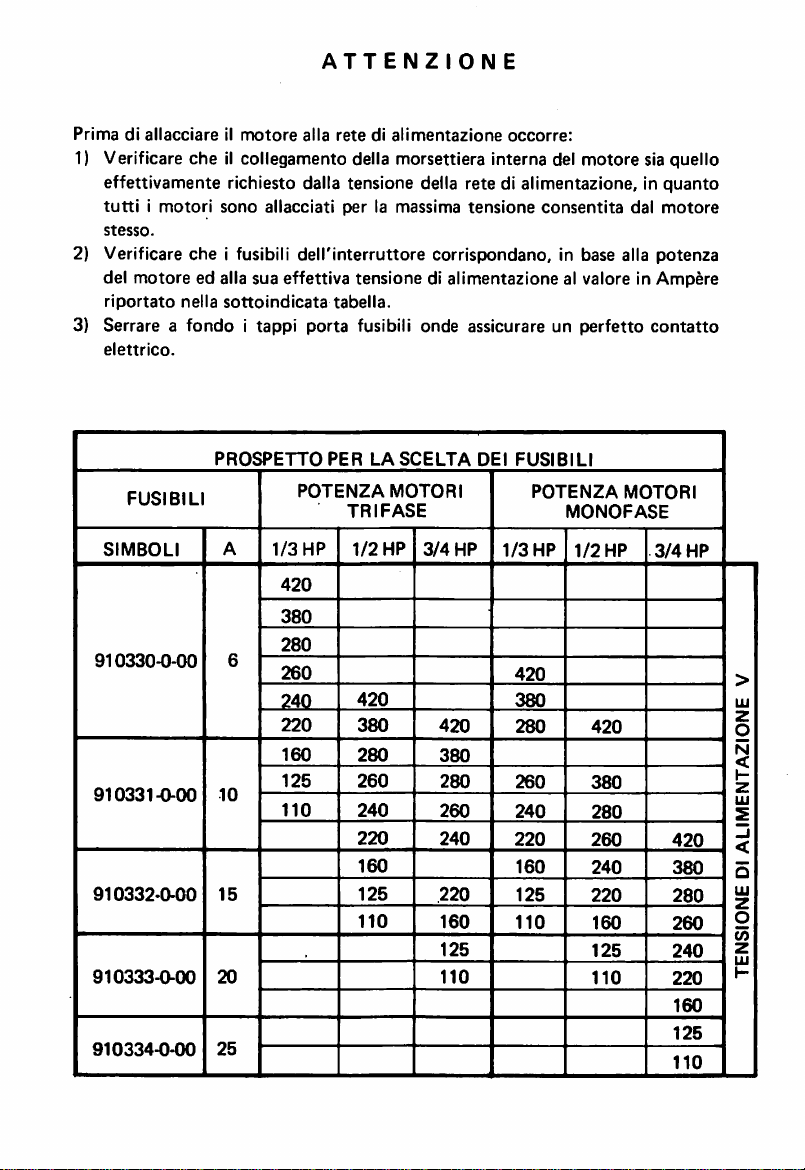
ATTENZIONE
Primadiallacciareilmotore
1) Verlflcare
che
il collegamento della morsettlera interna del motore sla quello
alia
retedialimentazlone
occorre:
effettivamente richiesto dalla tensione della rete di alimentazione, in
tuttiimotori
stesso.
2) Verificare
del
motore
riportato
3) Serrare a
elettrico.
FUSIBILI
SIMBOLI
910330-0-00
910331-0-00
910332-0-00
910333-0-00
910334-0-00
sono
allacciati
che
i fusibili
dell'interruttore
ed alia sua effettiva
nella
sottoindicata
fondoitappi
PROSPETTO
POTENZA
A
1/3
HP
420
380
280
6
260
240
220
160
10
15
20
25
125
110
per
la massima
corrispondano, in base alia
tensionedialimentazione
tabella.
porta
fusibili onde assicurare un
PER
LASCELTA
MOTORI
TRIFASE
1/2
HP
3/4
420
380
280
260
240
220
160
125
110
420
380
280
260
240
220
160
125
110
tensione
DEI
HP
FUSIBILI
POTENZA
1/3
HP
420
380
280
260
240
220
160
125
110
consentita
al valore in
perfetto
MONOFASE
1/2
HP
420
380
280
260
240
220
160
125
110
quanto
dal
motore
potenza
Ampere
contatto
MOTORI
3/4
420
380
280
260
240
220
160
125
110
HP
•>
UJ
z
o
N
<
1-
z
UJ
s
-J
o
UJ
2
O
(0
z
UJ
K
Page 3
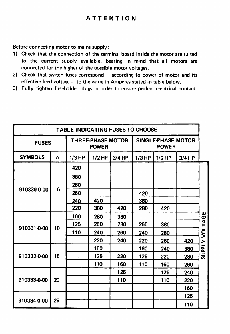
ATTENTION
Before connecting
1)
Check
that
to
the
connected
2) Check
that
effective
motor
to mains supply:
the
current
for
connection
supply
the
higher of
of
the
available,
the
switch fuses correspond —according to power of
feed voltage —tothe
value in
3) Fully tighten fuseholder plugs in
FUSES
SYMBOLS
910330-0-00
910331-0-00
910332-0-00
910333-0-00
910334-0-00
TABLE
A
6
10
15
20
25
INDICATING
THREE-PHASE
POWER
1/3
HP
1/2
420
380
280
260
240
220
160
125
110
420
380
260
240
220
125
110
terminal
bearing
possible
order
HP
280
160
board
inside
the
motor
in
mind
that
motor
voltages.
Amperes
statedintable
to ensure perfect electrical
FUSES
MOTOR
3/4
420
380
280
260
240
220
160
125
110
TO
HP
CHOOSE
SINGLE-PHASE
POWER
1/3
HP
1/2
420
380
280
260
240
220
160
125
110
420
380
280
260
240
220
160
125
110
all
motor
below.
HP
are
motors
and its
contact.
MOTOR
3/4
suited
are
HP
420
380
280
260
240
220
160
125
110
8-
D
V)
UJ
O
<
1-
O
>
>-
Page 4
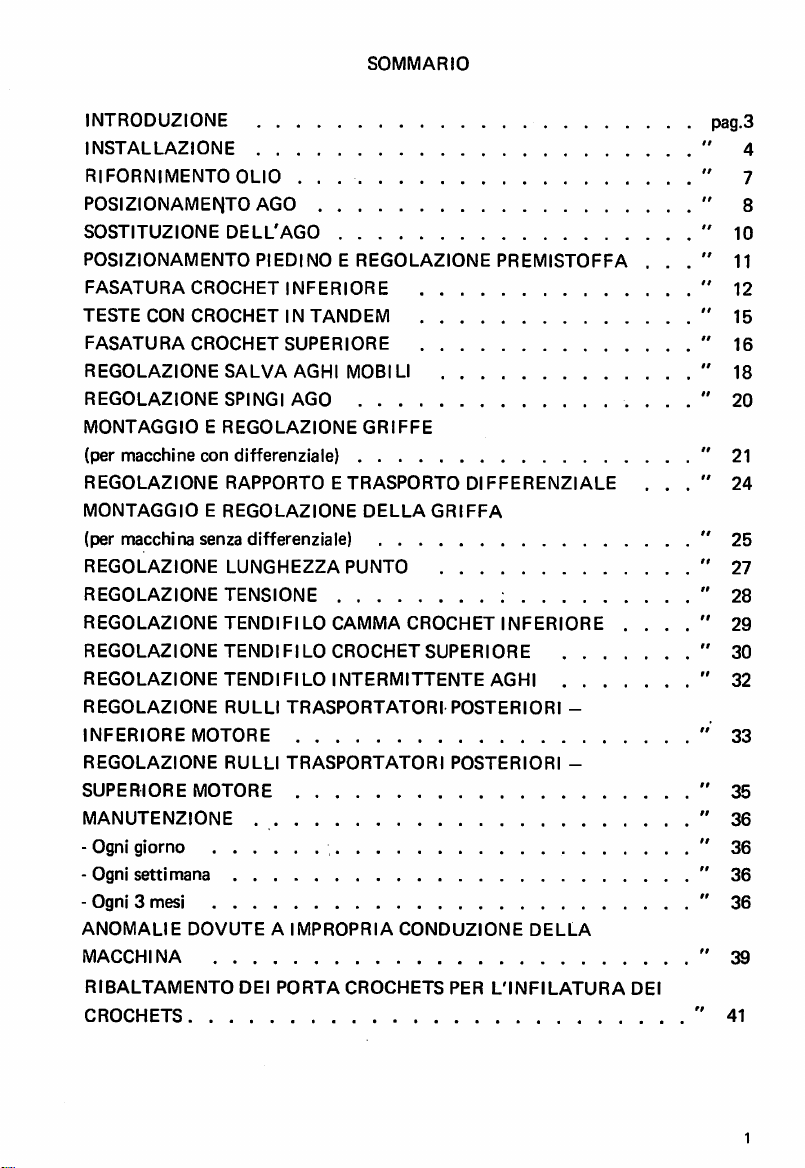
SOMMARIO
INTRODUZIONE
INSTALLAZIONE
RIFORNIMENTO
POSIZIONAMENTO
SOSTITUZIONE
POSIZIONAMENTO
FASATURA
TESTE
CON
FASATURA
REGOLAZIONE
REGOLAZIONE
MONTAGGIOEREGOLAZIONE
(per
macchine
REGOLAZIONE
MONTAGGIOEREGOLAZIONE
OLIO
AGO
DELL'AGO
PIEDINOEREGOLAZIONE
CROCHET
INFERIORE
CROCHETINTANDEM
CROCHET
con
SUPERIORE
SALVA
SPINGI
AGHI
AGO
differenziale)
RAPPORTO
MOBI
GRIFFE
ETRASPORTO
DELLAGRIFFA
PREMISTOFFA
LI
DIFFERENZIALE
. .
. .
(per macchina senza differenziale)
REGOLAZIONE
REGOLAZIONE
REGOLAZIONE
REGOLAZIONE
REGOLAZIONE
REGOLAZIONE
INFERIORE
REGOLAZIONE
SUPERIORE
MANUTENZIONE
LUNGHEZZAPUNTO
TENSIONE
TENDIFILO
TENDI
Fl LO
TENDIFILO
RULLI
TRASPORTATORI
MOTORE
RULLI
MOTORE
TRASPORTATORI
CAMMA
CROCHET
CROCHET
SUPERIORE
INTERMITTENTE
POSTERIORI
POSTERIORI
INFERIORE
AGHI
. . .
-
-
- Ognl glorno
- Ognl
settlmana
- Ognl 3 mesi
ANOMALIE
MACCHINA
RIBALTAMENTO
DOVUTEAIMPROPRIA
DEI
PORTA
CROCHETS
CONDUZIONE
PER
DELLA
L'INFILATURA
DEI
CROCHETS " 41
Page 5
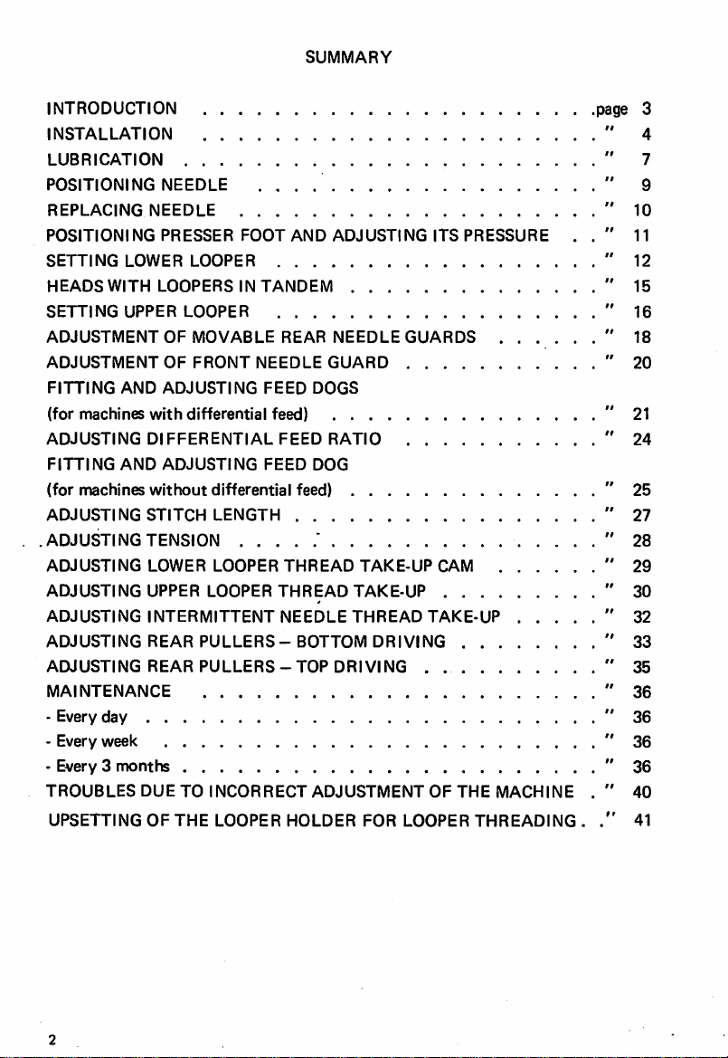
SUMMARY
INTRODUCTION page 3
INSTALLATION
LUBRICATION
POSITIONING
REPLACING
POSITIONING
SETTING
HEADS
SETTING
ADJUSTMENT
ADJUSTMENT
FITTING
(for
machines
ADJUSTING
FITTING
(for
machines
ADJUSTING
ADJUSTING
ADJUSTING
ADJUSTING
ADJUSTING
ADJUSTING
ADJUSTING
MAINTENANCE
- Every
day
- Every
week
- Every 3
TROUBLES
UPSETTING
NEEDLE
NEEDLE
PRESSER
LOWER
WITH
LOOPERS
UPPER
OF
OF
AND
ADJUSTING
with
DIFFERENTIAL
AND
ADJUSTING
without
STITCH
TENSION
LOWER
UPPER
INTERMITTENT
REAR
REAR
months
DUE
OF
. , .
FOOT
AND
LOOPER
IN
TANDEM
LOOPER
MOVABLE
FRONT
differential
REAR
NEEDLE
FEED
feed)
FEED
FEED
differential
LENGTH
LOOPER
LOOPER
THREAD
THREAD
NEEDLE
PULLERS-BOTTOM
PULLERS-TOP
TO
INCORRECT
THE
LOOPER
HOLDER
ADJUSTING
NEEDLE
GUARD
DOGS
RATIO
DOG
feed)
TAKE-UP
TAKE-UP
THREAD
DRIVING
ADJUSTMENT
FOR
GUARDS
DRIVING
LOOPER
ITS
PRESSURE
CAM
TAKE-UP
.
OF
THE
. . . . .
. . . .
MACHINE
THREADING
4
7
9
10
11
12
15
16
18
20
21
24
25
27
28
29
30
32
33
35
36
36
36
36
40
41
Page 6
INTRODUZIONE
Abbiamo
puntoemanutenzione
LIBERA"
convenientemente
Queste macchine giungono a Voi
permettono
dipendono
raccolto
nel
che
riteniamo
usareilnostro
di
garantirneladurata
notevolmente
presente
delle
libretto
macchine
possano esserVi utili
prodotto.
dopo
dall'uso
e dalla
alcune
note
relative alTinstallazione, messa a
Rimoldi
Serie
per
"BASE
meglio
CILINDRICA
conoscere
e piu
scrupolosi controlli e rigorosi collaudi che ci
e I'efficienza, ma Vi
manutenzione
ricordiamo
che
saranno
che
queste
riservate alle
macchine, pertanto prime deM'impiego, Vi consigliamo nel Vostro interesse di
consultare
contenute.
INTRODUCTION
This
booklet
attentamente
contains
some
questo
notes on
fascicolo e seguire con cura le istruzioni in esso
* * *
the
installation,
operation
and
maintenance
Rimoldi "CYLINDER BED" which should be useful to owners and should help
themtobecome
Before despatch,
ensure its durability
depend very much on how
therefore in the interest of the owner to read this booklet carefully and follow
instructions
familiar
the
given in it.
with
the
machine
and
derive
the
best
use
from
it.
machine was carefully checked and thoroughly tested to
and
efficiency; it must, however, be remembered
the
machine is operated and maintained, and it is
that
these
thje
E
of
Page 7

INSTALLAZIONE
Per
rinstallazione
della
testa
ed il suo
collegamento
conilmotore
(gia
montato
bancale), mediante cinghia di trasmissione, procedere come segue:
1.
premere
piastra di
2.
plazzare
orecchlette
3. collegare il
4. collegare il
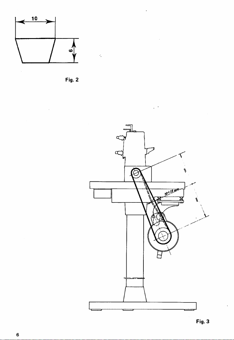
cinghia di trasmissione sezione
(fig. 3).
5. registrare la
da
non
con
forza i
sostegno.
la
macchlna
della bacinella sui
tirante
1 (fig. 1) alia leva alza piedino della macchina
volantino
tensione
consentire
slittamenti,
quattro
tamponi
sul
bancale,
quattro
della macchina alia puleggia del
ammortizzatori
centrando
tamponi
10x6
(fig. 2) secondo lo schema di collegamento
le sedl
ammortizzatori
della cinghia agendo sullo snodo
ma
avendo
curadinon
sugli appositi perni della
coniche
motore
attacco
tenderia
ricavate
2 (fig. 1).
con
I'apposita
motore,inmodo
eccessivamente
onde evitare sovraccarichi sugli alberi delle pulegge e non compromettere la
durata della cinghia stessa. Si ha la giusta tensione quando, premendo con la
mano al
cedimento
centro
del
della cinghia, di
tratto
indicato in fig. 3, si verifica una freccia, cioe un
10-15
mm.
6. livellare la testa della macchina affinche la cinghiasitrovi sul piano normale
assi delle pulegge e al centro delle loro gole. Per I'operazione di livellamento,
agire sui perni sostegno testa 3 (fig. 1), avendo cura di bloccare successivamente
gli
appositi
dadi.
*♦*
sul
nelle
agli
INSTALLATION
Installation of
the
stand) by means of driving belt is carried
1. Press
2. Place
on
the
3.
Connect
4. Connect machine handwheel to
(fig. 2) as
5. Adjust the belt tension by
the
overloading
correct
3,
the
6.
Level
thus
pins 3 (fig. 1), making suretolock
the
the
four
the
machine on
four
shock
stay-rod
showninsketch
belt
cannot
the
when,
machine
shock absorbers down hard on
pulley shafts and
putting
head
and
connectiontothe
out
the
stand, centering
the
absorbers 2 (fig. 1).
1 (fig. 1)tomachine presser
motor
pulley with
(fig. 3).
slip,
moving
but
the motor coupling articulated joint
taking
care
not
shortening
manual pressure on
the
motor
(already
as follows:
the
pins on
the
conical housings of
foot
lifter lever.
10x6
to
makeitover-taut,
the
life of
the
centreofthe
mounted
support
the
plate.
sump
section driving belt
soi
to avoid
belt.
The
tension is
part
indicated
belt yields about 10-15 mm. (3/8"-9/16").
the machine head so that the belt is perpendicular to the pulleyaxes and
centered in their races. For
the
levelling operation, adjust
them
again afterwards with
the
head
the
relative nuts.
support
on
lugs
that
in fig.
Page 8
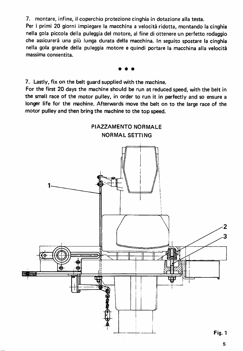
7. montare, infine, il coperchio protezione cinghia in dotazione alia testa.
Per 1primi 20 giorni implegare la macchlna a velocita ridotta, montando lacinghia
nella gola piccola della puleggiadel motore, al fine di ottenere un perfetto rodaggio
che assicurera una
piCi
lunga durata della macchina. In seguito spostare la cinghia
nella gola grande della puleggia motore e quindi portare la macchina alia velociti
massima
consentita.
* * *
7. Lastly, fix on
the
belt guard supplied with
the
machine.
For the first 20 days the machine should be run at reduced speed, with the belt in
the small race of the motor pulley, in order to run it in perfectly and so ensure a
longer life for the machine. Afterwards move the belt on to the large race of the
motor
pulley
and
then
bring
the
machinetothe
PIAZZAMENTO
NORMAL
top
NORMALE
SETTING
speed.
Fig. 1
5
Page 9
< >
Fig. 2
Fig. 3
Page 10
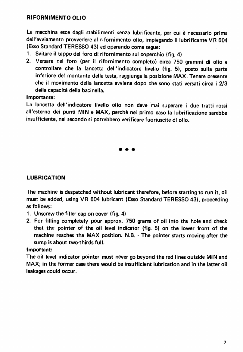
RIFORNIMENTO
La
macchina
esce
OLIO
dagli
stabilimenti
senza
lubrificante, percui e
necessario
prima
deiravviamento provvedere al rifornimento olio, ImplegandoI!lubrificante VR 604
(Esso
StandardTERESSO 43) ed operando come segue:
1. Svitare il tappo del foro di rifornimentosulcoperchio
2.
Versare
nel foro (per il rifornimento completo) circa 750
(fig.
4)
grammi
di olio e
controllare che la lancetta dell'indicatore livello (fig. 5), posto sulla parte
inferiore del montante della testa,
che il movimento della lancetta avviene dopo che sono stati versati circa i
della
capacita
Importante:
La lancetta dell'indicatore
della
bacinella.
livello
raggiunga
la posizione
MAX.
Tenere presente
2/3
olio non deve mai superare i due tratti rossi
all'esterno dei punti MIN e MAX, perche nel primo caso la lubrificazione sarebbe
insufficiente, nel secondo si potrebbero verificare fuoriuscite di olio.
« « «
LUBRICATION
The machine is despatched without lubricant therefore, before starting to run it, oil
must be added, using VR
as
follows:
1. Unscrew
2.
For
that
filling
the
the
filler cap on cover (fig. 4)
completely
pointer of
machine reaches
sumpisabout
Important:
The
oil level
MAX;inthe
leakages
could
two-thirds
indicator
former
occur.
604
lubricant (Esso Standard TERESSO 43), proceeding
pour
approx.
the
oil level indicator (fig. 5) on
the
MAX position. N.B. - The pointer starts moving
full.
pointer
case
must
there
wouldbeinsufficient
750
never go
gramsofoil
beyond
the
lubrication
into
the
red lines
the
hole
and
lower front of
after
outside
andinthe
MIN
latter
check
the
the
and
oil
Page 11
POSIZIONAMENTO
Gli
aghi
sono
radialmente
mediante
trovanoalcentro
Con
barra
ago
risultare
Nel
effettuarelaregolazlone.
stessasitroviinbattuta
applicato
Bloccareafondolavite
Sia
aghi (fig. 7}
rilevata
quella
caso
che
sulla
perleteste
fra la
punto
punta
AGHI
infilati a
delle
tuttainaltoladistanza
indicata
cio
fascettainmodo
a 2
battuta
vite. Si ha la
feritoie
non
s! verlficasse
aghi
esistenti sulla placca
sulla
tabelladlfasatura
Serrare
verso
della
fascetta.
(fig. 6) a
ornamento
dell'agodidestra
nell'apposito
quindilavite
I'alto
che
con
foro
corretta
tocchiilmorsetto
punto
posizione
"a"
fra
che
allentare
o senza
ed il
la vite A (fig. 6) della fascetta B ed
controlabarra
catenella
copertura,ladistanza
piano
punta
della
del
morsettoesono
degll stessi
d'ago
(figg. 6-7).
agoepiano
corredalatesta.
della
fascetta
ago.
porta
ago.
doppia,
placca
che
ago.
bloccati
quandolepunte
della
placca
avendo
Regolareilperno
perleteste
cura
"a"
che
a 2 o 3
deve essere
si
deve
la
C
Page 12
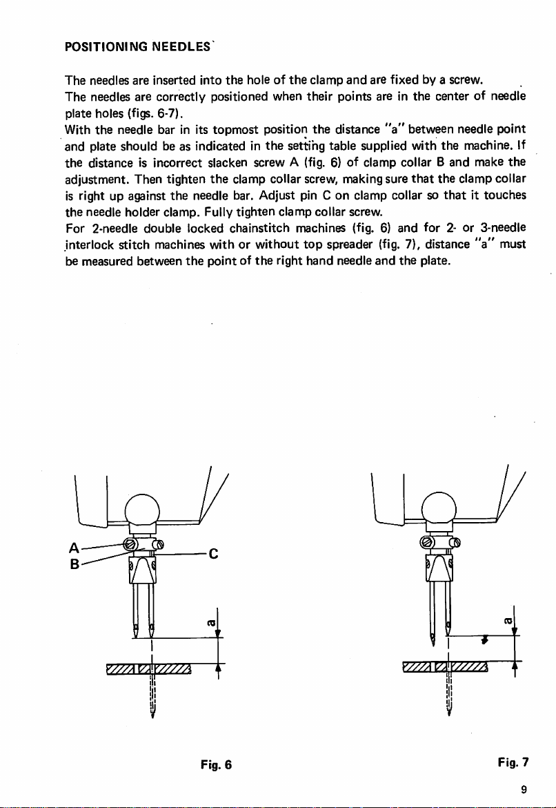
POSITIONING
The
needles
The needles are correctly positioned when their points are in
plate holes (figs. 6-7).
With the needle bar in its topmost position the distance
and plate should be as indicated in
the
distance is incorrect slacken screw A (fig. 6) of clamp collar B and make
adjustment. Then tighten
is right up against
the
needle
For 2-needle
interlock stitch machines with or without
be measured between
are
holder
double
NEEDLES
inserted
into
the
holeofthe
the
the
clamp collar screw, making sure
the
needle bar. Adjust pin C on clamp collar so
clamp.
Fully
tighten
locked chainstitch machines (fig. 6) and
the
pointofthe
clamp
setting table supplied with
clamp
collar
top
spreader (fig. 7), distance
right
hand
needle
and
screw.
are
fixed
by a screw.
the
center of needle
"a"
between needle point
that
for
and
the
plate.
the
the
that
machine. If
the
clamp collar
it touches
2- or 3-needle
"a"
must
0}^
I
_llr
o
Fig.
6
Fig.
7
9
Page 13
SOSTITUZIONE
AGO
Spegnere il motore ed assicurarsi, premendoilpedale, che la macchina sia
assolutamente
ferma.
Ruotare normalmente il volantino portando la barra ago tutta In alto. Allentare la
vlte serra ago A (fig.9), estrarre I'ago e sostltulrlo con il nuovo. Tenere presente che
I'incavo passaggio crochet deve essere rivolto verso I'lnterno della macchina.
Servendosi
della
pinzaIndotazlone, accertarsi che
I'ago
appoggi
sul fondo foro.
Avvltare, senza eccedere nel bloccagglo, la vlte serra ago, avendo cura dl non varlare
I'orientamento
dell'ago.
* * *
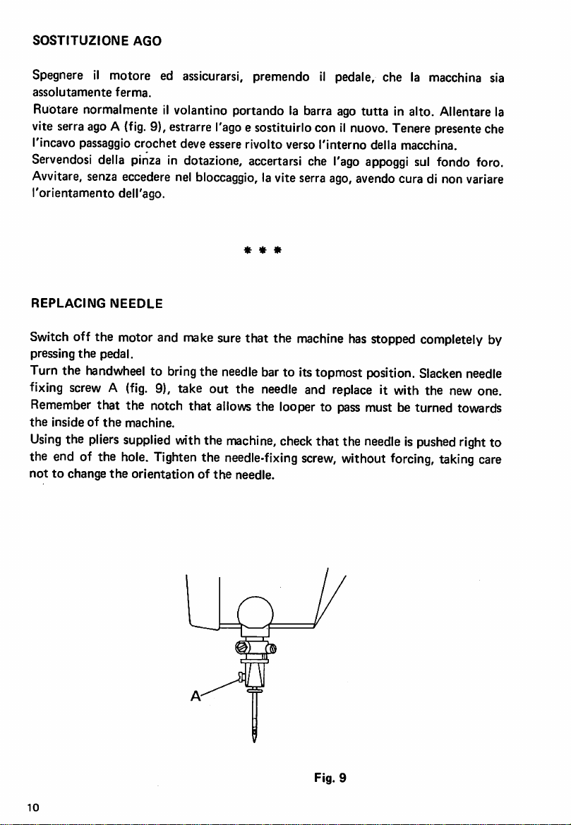
REPLACING
Switch
pressing
Turn the
fixing
the
Using
off the motor and
the
screwA(fig.
Remember
Insideofthe
the
pedal.
handwheel
that the notch that
pliers
the end of the
nottochange
NEEDLE
make
surethat the
machine
to bringthe needlebar to Itstopmost position.
9), take out the
machine.
supplied
hole.
Tighten
the
orientationofthe
allows
withthe
the
needle
and
the looper to passmust be turned towards
machine,
needle-fixing
needle.
check
that the
screw,
has
stopped completely by
replace
It with the new one.
needleIspushed
Slacken
needle
rightto
without forcing, takingcare
Fig. 9
10
Page 14
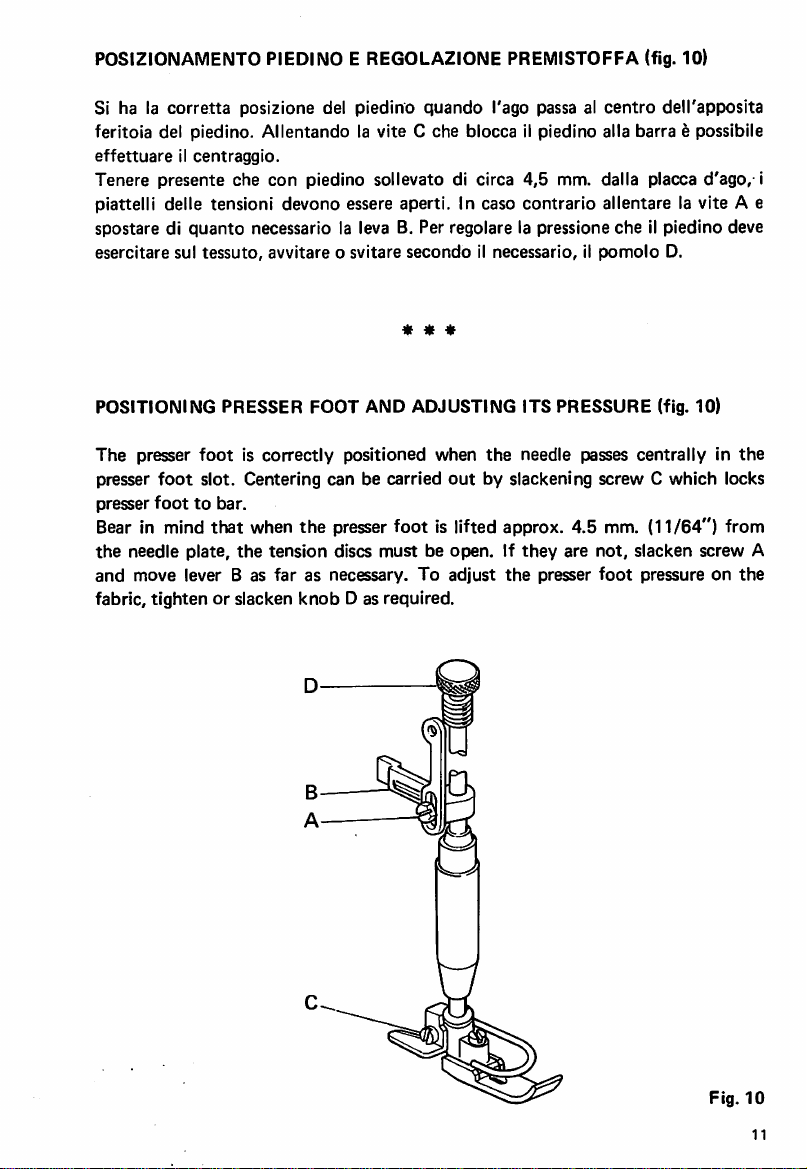
POSIZIONAMENTOPIEDINO E REGOLAZIONE PREMISTOFFA (fig. 10)
Si ha la
corretta
posizlone del piedino quando I'ago passa al
centro
deH'apposlta
feritola del piedino. Allentando la vite C che blocca il piedino alia barra e possibile
effettuareilcentraggio.
Tenere presente che
con
piedino sollevato di circa 4,5 mm. dalla placca d'ago, i
piattelli delle tensioni devono essere aperti. In caso contrario allentare la vite A e
spostare di
esercitare
quanto
sul
necessario la leva B. Per regolare la pressione che il piedino deve
tessuto,
avvitareosvitare
secondoilnecessario,ilpomolo
* * *
D.
POSITIONING PRESSER FOOT AND ADJUSTING ITS PRESSURE (fig. 10)
The
presser
presser
presser
footiscorrectly
foot
slot. Centering can be carried
foottobar.
positioned
when
the
needle passes
out
by slackening screw C which locks
centrallyinthe
Bear in mind that when the presser foot Is lifted approx. 4.5 mm. (11/64") from
the
needle plate,
and
move
fabric, tighten or slacken
the
lever B as
tension
discs
must
far
as necessary.Toadjust
knob
D as required.
be open. If
the
they
presser
are
not,
slacken screw A
foot
pressure on
the
Fig.
10
11
Page 15

FASATURA
Inserire fino a battutailcrochet A neirapposita sede del porta crochet e bloccarlo
sul piano dl riferimento del gambo con la vite B (fig. 11).
Controllarecon il
esso corrispondano.
come
segue:
1. Per ottenere la quota
L della fascetta Me agire sul tirante N della biella (fig. 13) sino ad ottenere la
quota
2. Per ottenere la quota 0,05
crochet
vite G (fig. 15) e registrare facendo
3. Sulle teste a punto ornamento tipo
durante la sua discesa, deve coincidere conilpunto di convergenza delle due
lineeche formano il profile inferioredella
Sulle
la
discesa
4. Gli
crochet flettendo. Per ottenere questa condizione e necessario che il
prolungamento
principale, risuiti tangente al diametro esterno della vite E.
SETTING
Fit
looperAright
screw
B (fig.
Check
the machine. Ifadjustments must be made, proceed as follows:
1. To
of
sleeve
distance indicated insetting table is obtained.
2. To obtain distance 0.05 mra
point of the
slacken screw G (fig. 15) and adjust by turning shaft H.
3.On171
the
convergence
On 174
during
(fig. 17).
4. In their downward stroke the needles must come into contact with the back of
the
extending from reference notch D (fig. 15) on main shaft would haveto be at a
tangenttothe
CROCHET
prescritta
e I'incavo dell'ago durante la sua corsa da destra a sinistra allentare la
teste 174 a 2
deve
aghi
nella
LOWER
11).
that the
obtain
measurements
distance
collar M and adjust stay-rod N of connecting rod
looper
and
173
downward
of the
2-needle
the
downward
looper
blade,
external
INFERIORE
fogliodifase
Nei
caso si dovessero effettuare alcune registrazioni operate
'b'
dalla
tabella
aghi,
essere
allineata
loro
discesa
ideale
della
LOOPER
down
in itsseat in the
"b"
(fig.
and the
interlock
movement
kines
double
stroke
bending
diameterofscrew
(allegato alia
fig. 12 portare ilcrochet
di fase.
(fig.
14) che rappresenta ladistanzafra la punta del
a punto
conilforo del
devonoentrare in contatto conildorso della
tacca di riferimento D
* * *
correspondtothose
12)
bring
ruotare
171
catenella
looper
looper
macchina)
I'albero H.
che le
misure
tutto
a destra, allentare lavite
e 173, la punta dell'ago interne,
lama
del crochet
(fig.
16)
doppia,lacrunadiogni
rispettivo
holder
inthe
fully
crochet
(fig.
15),
and fix it in
setting
to the
right,
(fig.
incisa
chart
slacken
(fig.
(fig.
14) which represents the distance between the
needle
stitch
of the
forming
locked
must
slightly.
notch
during
itsstroke
machines
the
chainstitch
be in
needle,
lower
line
the
point
ofthe
must
coincide
outlineof the
machines
with
the
the eye of each
hole
To obtain this condition an
E.
from
inside
with
looper
ofthe
needle,
blade
relative
imaginary
riportate su di
ago
durante
17).
lama
del
sull'albero
position
supplied
with
with
screw
13)
until
the
right
to left,
during
the
point
of
(fig.
16).
needle
looper
line
L
12
Page 16

Attenzione • in caso dl sbloccaggio delle viti E ed F (fig. 15), per ottenere le
condizioni
Testremita
Attention: If screws E and F (fig. 15) are undone, in order to obtain the above
conditions
reference
di cui
della
taccadiriferimento
the
external
notch
D.
Fig. 11
sopra,lafaccia
esterna
D.
* * «
planeofeccentricCmust
deU'eccentricoCdeve
just
graze
the extremity of
sfiorare
Fig.
13
t
Fig.
Fig.
12
14
Page 17

Fig.
15
Fig.
16
Fig.
14
17
Page 18

TESTE
CON
CROCHET
IN
TANDEM
Ambedueicrochet,
crochet
II gruppo
qualeemontato.
laterale
porta
La biella B
alternatlvo.
Per
quanto
capltolo
relative
HEADS
riguarda la fasatura del
"Teste
Tabelledlfasatura.
WITH
nel
delle
testeapunto
crochet
trasmette
con
LOOPERS
loro
movimento
A riceveIImoto
inoltre ai
crochet
IN
TANDEM
laterale",
catenella
porta
crochet,
* * *
descrivono
doppia,
la stessa
chenesono
traiettoria
oscillatorlo traversale dal
crochet
mentre
C e DIImoto
operate
secondo
per I valorl dl fase attenersi alle
elittica
provviste.
contralbero
longltudlnale
le IstruzlonI nel
del
sul
The movement of both the loopers describes the same elliptic trajectory as the side
looper on double locked chalnstltch machines fitted with this. The looper holder
the
assembly A receives
tranverse rocking movement from the countershaft on
which It Is mounted. Connecting rod B transmits alternate longitudinal movement
to
looper
holdersCand
For settingthe
loopers,
lower looper" and keep to
D.
follow
the Instructions
the
setting values given In the relative Setting Tables.
given
inthe chapter
headed
"Setting
©
crochetInTandem
LoopersinTandem
15
Page 19

FASATURE
CROCHET
SUPERIORE
Controllare,
corrispondano.
Nel case si dovessero effettuare alcune registrazioni operare come segue:
1.
(quota
della corsa del
Per modificare la
biella
con
'e').
B.
il foglio fase allegato ad ogni macchina che le misure
Diminuendo la
crochet,
quota
quota
'h',
riportata
aumentandolaquota
'h'
allentare la vite A (fig. 21) e spostare la testa di
in fig.
'h'
si diminuisce.
21,siottiene
'e''fe 'g'
I'aumento
2. (quota 'f'). Per ottenere la quota'fallentare la vite C (fig. 19) e ruotare il porta
crochet.
3. (quota 'g'). Per ottenere la quota 'g' allentare la vite D (fig. 20) e ruotare il
crochet. Far attenzione che I'anello di fermo F sia sempre a battuta contro il
porta
crochet
SETTING
Check with setting chart supplied with each machine that distances
UPPER
E (fig.
LOOPER
22).
* * *
"e",
"f"
and
"g" are correct.
Ifadjustments are necessary, proceed as follows:
1.
(distance
increased; by increasing distance
slacken screw A (fig. 21) and shift bigend of connecting rod B.
2.
(distance
holder.
3.
(distance
Make
"e")Byreducing
"f")Toobtain
"g") To
surethat
locking
obtain
distance
distance
distance
ring F is
"h",
showninfig.21,
"h"
it is reduced. To modify distance
"f",
slacken
"g",
slacken
always
closeup againstlooper holder E
screwC(fig,
screwD(fig.
the
19)
20)
looper
and
turn
andturn
stroke
looper
looper.
(fig.
"h"
22).
is
Fig.
18
16
Fig.
19
Page 20

Fig.
20
Fig. 21
22
Fig.
17
Page 21

REGOLAZIONE
Le
teste
serie
Detto salva ago e
punto
sara indispensabile posizionare il salva ago
riportate
1.
in fig.
Regolazionesuporta
SALVA
171,173e174
AGHI
montato
23,
procedendo
griffa
MOBILI
sono
dotate
sul portagrlffa; percio ad ogni varlazione di lunghezza del
come
senza
differenziale
Ruotare il volantino fino a portare la griffa
Allentareildado
condizioni
descritte.
della fig.
2. Regolazione su
Le
operazioni
fare
attenzione
tenendo
piano
presente
di quelle della griffa differenziale.
A e
far
scorrere il salva ago B (fig. 24) fino a
23.
Bloccare il
porta
griffa differenziale (fig. 25)
sono
le stesse del
affinche
che
le cuspidi dei
non
venga
di salva
segue:
dado
paragrafo
spostata
dentidiquesta
* * *
ago
mobile.
onde
ottenere
tutta
in avanti (verso I'operatrice).
A e
controllarelecondizioni
1; in
questo
caso
peroenecessario
verticalmente
la griffa principale,
devono
essere sullo stesso
le condizioni
trovare
sopra
le
ADJUSTMENT
OF
MOVABLE
REAR
NEEDLE
GUARDS
Class 171, 173 and 174 heads are fitted with movable rear needle guard.
the
This needle guard is mounted on
feed dog holder; therefore every time the
stitch length is altered it is essential to position the rear needle guard in order to
obtain
the
conditionsshown in fig. 23, proceeding as follows:
1.
Adjustmentonfeed
Turn handwheel until
dog
holder
without
the
feed dog is in its most forward position (towards
differential
operator). Slacken nut A and slide rear needle guard B (fig. 24) until it is
positioned as shown in fig. 23. Lock
above.
nut
A and check conditions described
2. Adjustment on differential feed dog holder (fig. 25)
The operations are the same as in paragraph 1; in this case, though, care must be
taken not to move
of
the
feed dog
dog.
18
the
main feed dog vertically, bearing in mind
teeth
must be on
the
same level as
thoseofthe
that
the points
differential feed
the
Page 22

01±02
Fig.
23
ix.
©
c
1
Fig.
A
B
24
or
r"
o
o
CCP
t:
r\
\.
Fig.
25
19
Page 23

REGOLAZIONE
Tutte
le teste serie 171 e
supporto
calettato
Le condizioni di
la
posizione
muovedadestra
dovra
trovarsi circa da 0,1 a
altezza
della
Per
ottenere
SPINGI
AGO
173
sul
porta
crochet
posizionamento
deila
punta
del
crochet
verso sinistra,
parte
superiore
tali
condizionisisbloccano
della
sonp
esatto
coincide
0,15
cruna
dotate
(fig. 26).
sono
rispetto
conlaposizione
mm dall'ago
dell'ago.
le viti A e B (fig. 26).
della vite A si regola lo spingi ago in verticale
con
Tallentamento
della vite B si regola
I'accostamento
* * *
di spingi ago
quelle
chesivedono
all'ago
rispetto
interne,
interne
all'altezza della
dello
montato
su apposite
in fig.
quandoilcrochet
del salva ago
con
lo spigolo alia stessa
Con
I'allentamento
cruna,
spingi ago agli aghi.
27.
mobile
mentre
Infatti
si
che
ADJUSTMENT
All Class 171 and
keyed
bracketonlooper
The
exact
in relationtothe
coincides
approximately
height as
OF
FRONT
173
NEEDLE
heads are
holder
fitted
(fig.
GUARD
26).
with
front
needle guard
positionings are those shown in fig. 27. The position of
the
with
the
0.1-0.15
top
partofthe
internal needle,
position
mm.
from
needle eye.
of
the
the
when
movable
internal
the
looper
rear
needle
moves
needle guard
with
the
mounted
from
on special
the
looper point
righttoleft,
that
corneratthe
must
To obtain this setting, slacken screws A and B(fig. 26). With screw A slackened
front
needle
guard
with
screwBslackened
canbeadjusted.
can be
the
adjusted
distance
vertically in relationtothe
between
the
front
needle guard
needle eye, while
and
the
needles
be
same
the
Fig.
20
Page 24

Q1+0.15
Fig. 27
MONTAGGiO E REGOLAZIONE
differenziale)
Montaggio griffe su
-
Montare
porta
con
griffa B.
porta
griffe
la vite C la griffa
• Montare la griffa principale D senza bloccaria a
E
tramiteledue
-
Collocareiltutto
griffa D
FITTING
feed)
£on
AND ADJUSTING
la A.
viti
sul
H.
braccio
FEED
GRIFFE
anteriore
porta
griffa ed allineare
* * *
DOGS (fig. 28)
(fig. 28) (per macchine con
differenziale A nella sua sede della slitta
fondo
sulla squadretta porta griffa
approssimativamente
(for
machines
Assembling feed dogsonfeed dog holders
-
Mount
front
meansofscrew
differential feed
C.
dog
A in its
seat
on slideoffeed
- Mount main feed dog D on feed dog holder bracket E by means of
without
- Set it all on
feed
screwing it
dog
A.
down
the
feed dog holder
completely.
arm
and
align feed dog D approximately with
with
dog
two
differential
holder
B by
screws H,
la
21
Page 25

Centratura
-
Allentareledue
griffe
viti
G.
- Montare la placca d'ago e centrare in senso laterale la griffa A nelle feritole della
placca d'ago spostando I'lntero gruppo differenziale F.
-
BIcccareleviti
- Allineare
G.
perfettamente
la griffa principale D.
- Togliere la placca d'ago. Smontare la squadretta porta griffa E ed eseguire il
bloccaggio a fondo della griffa Dsulla squadretta E
- Rimontare di nuovo la squadretta E e bloccare leggermente con la vite
tramite
le viti H.
0.
- Rimontare la placca d'ago e, facendo ruotare il volantino nel senso di marcia, far
scorrere le griffe nella placca d'ago.
- Se le griffe toccassero la placca d'ago sul fondo delle feritoie, allentare la vite P
della
forcella
Q.
- Ruotare il gruppo F ed eseguire la centratura delle griffe rispetto alle feritoie della
placca
d'ago
- Bloccare leggermente la
vite
P.
« IK
Centering
-
Slacken
- Mount needle plate and center feed dog A laterally in
moving
-
Tighten
the
feed
dogs
the
two
screws
G.
the
whole differential assembly F.
screws
G
the
needle plate slot,
- Align main feed dog D accurately
-
Remove
the needle plate.
Disassemble
feed dog holder bracket E and fix feed dog
D firmly on bracket E by means of screws H.
-
Re-mount
- Re-mount needle plate and, turning handwheel in
bracketEand
fasten
lightly
with
screw
0.
the
normal direction, make
feed dog run in needle plate.
- If the feed dog touches
fork
Q.
the
bottom of
the
needle plate slot, slacken screw P of
- Turn assembly F and center feed dog in relation to needle plate slot.
- Lightly
22
fasten
screw
P.
Page 26

=o
a
a.
LL O UJ
F
^2=7"
u
QQ
H
SS
CN (N
Page 27

REGOLAZIONE RAPPORTO TRASPORTO DIFFERENZIALE (fig. 29)
AllentareIIdadoVcon
I'apposita chiave e spostare la leva L nel
avere la posizione desiderata. Bloccare quindi il dado V.
* * *
ADJUSTING
Slacken
positionisobtained.
DIFFERENTIAL
nut
V using special
Then
FEED RATIO (fig. 29)
spanner
tighten
nut
and
V.
move lever L in
settore
sectorTuntil
T fino ad
the
desired
\ \
2ZZZ^
Fig.
24
29
Page 28

MONTAGGIO E REGOLAZIONE DELLA
GRIFFA
(per macchine senza
differenziale) (fig. 30)
Montaggio griffa su
porta
griffa
- Montare la griffa A nelTapposlta sede della squadretta porta griffa Be inserire la
vite
C.
- Bloccare la
Centratura
-
Allentareledue
squadrettaBcon11dado
della griffa
vltl
E.
D e la griffa A
con
la vlte C.
- Montare la placca d'ago e centrare In senso laterale la griffa A nelle feritoie della
placca
d'ago
spostando
I'intero
gruppo
F.
- Bloccare le viti E far ruotareIIvolantino nel senso dl marcia e far scorrere la griffa
sulla
placca
d'ago.
- Se la griffa toccasseIIfondo
della
forcella
-
RuotareIIgruppo
placca
-
Bloccare
Alllneamento
-
AllentareIIdado
H.
F ed eseguire la
d'ago
leggermentelavlte
griffa
rispettoa!piano
D edIIgrano
- Allineare la cresta del denti rispetto al piano della placca
I'eccentrlco M.
FITTING
30)
(fig.
AND
Serrare
ADJUSTING
delle feritoie della placca d'ago, allentare la vlte G
centratura
G.
placca
L.
della griffa
d'ago.
rispetto
d'ago
II grano L e
bloccareIIdado
* * *
FEED
DOG
(for
D.
machines
without
alle feritoie della
manovrando
differential feed)
Assembling
- Mount feed dog A in
screw
-
Lock
-Centering
-
Slacken
- Mount needle plate
the
Tighten
-
needle
- If
fork
-
Turn
- Lightly
Alignmentoffeed
-
Slacken
- Align
eccentric
-
Tighten
feed
C.
bracketBwith
the
feed
the
two
whole
assembly
screwsE,turn
plate.
the
feed
dog
H,
assemblyFand
fasten
nutDand
the
peak of
M.
grub
dogonfeed
nutDand
dog
screws
and
F.
touches
center
screw
G.
dogtoneedle
grub
the
screwLand
dog
holder
the
special seat on feed dog holder
feed
dogAwith
E.
screw
bracketBand
C.
center feed dog A laterally in needle plate slot, moving
handwheelInnormal
the
bottomofthe
feed
dog
In relationtoneedle
plate
surface
screw
L.
teeth
in relation to
nut
D.
direction
needle plate
the
and
make
feed
slot,
slacken
plate
slot.
needle plate surface by moving
screwGof
dog
insert
run
25
In
Page 29

Regolazioneinaltezza
• Regolare in
sporga
C.
dal
altezza
piano
la griffa in
della
placca,
modo
di mm.
che
1,2.
0*0
nella massima
Fissare
quindi
alzatalacresta
la griffa
mediantelavita
dei
denti
Adjustmentinheight
- Adjust the feed dog in height so that, when it is' raised to the maximum, the
peaks of
-
Then
the
fasten
teeth
feed
jut
dog
out
with
1.2
screw
mm.
C.
from
the
needle plate surface.
Fig.
26
30
Page 30

REGOLAZIONE
La
lunghezza
questo
scopo
Premereilperno
stesso possa inserirsl nella tacca del regolatore C, quindi ruotare con forza il
volantino B
I'indicatore D, rilasciarequindi il perno A.
ADJUSTING STITCH LENGTH (fig. 31)
LUNGHEZZA
del
punto
puo
e graduate
esternamente.
A e far
fincheilnumero
PUNTO
essere
(fig.
31)
varlata
medlanteIIvolantinoB(fig.
Perlavariazlone
procedere
ruotareilvolantino8finoache
corrispondente
* * *
alia
lunghezza
come
I'estremita
desiderata
31)
segue:
del
coinclda
che
perno
con
a
Thestitch
there
To make
Press
of
regulatorC,next
the
lengthisvariedbymeans
is a
graduated
the
pin
A and turn
desired
stitch
ofthe
scale.
variation, proceed as follows:
handwheelBuntil
forcibly
length
turn
coincides
handwheelBuntil
with
markD,then
handwheelB,onthe outer partof
which
the extremity of the pinfitsinto the notch
the
number
release
corresponding
pinA.
to
Fig. 31
27
Page 31

REGOLAZIONE
II
filo viene premuto fra 1due dischi A (fig. 32) della tensione, dalla molla situata
TENStONE
neirinterno del pomolo, quindi per avere la giusta formazione del punto e
necessario regolare la pressione della motla, avvltando o svitando11pomolo B della
tensione
Nella maggior parte dei casi, la tensione del filo per crochet inferiore viene tenuta
stessa.
lenta e la regolazione si effettua mediante la tensioncina appllcata sulla camma
tendifilo.
ADJUSTING
The
thread
TENSION
is held between
the
two
discs A (fig. 32) of
the
tension by
the
spring
inside the knob. So, to obtain the correct stitch formation, it Is necessary to
regulatethe pressureof the spring byscrewingor unscrewing knob Bof the tension.
In most cases, the tension of the lower looper thread is kept slack and adjustment is
made by means of
the
small tension on
the
thread tensioning cam.
Fig.
32
Page 32

REGOLAZIONE
173)
I due dischi della camma tendifilo debbono essere perfettamente centrati con la
levetta fermafilo A e Tastina B (fig. 33).
Per eseguire
della
camma;
TENDIFILO
detta
regoiazione allentare la vlte C dell'anello D e le viti E sul mozzo
far
scorrere
CAMMA
assialmente
CROCHET
camma
ed anello
INFERIORE
suH'albero
(per teste 171 e
principale
fissarll entrambi nella corretta poslzione tenendo presente che il mozzo della
camma deve fare rasamento contro j'anello D. L'anello D mediante lasplna F, che
trova riscontro nella ferltoia G del mozzo della camma H, costitulsce11limlte dl
escursione
Tenere inoltre presente che quandoIIcrochet inizia la sua corsa verso destra deve
tendere11suo
radlale
filo.
della
camma
stessa.
Accertarsidella corretta regoiazioneeffettuando alcune prove di cucitura.
* * *
e
ADJUSTING LOWER LOOPER THREAD TAKE-UP CAM (for 171 and
heads)
The two thread
lever A
and
rod
take-up
8 (fig.
33).
cam
discs
mustbeperfectly
centered
withthread
173
retaining
To make the adjustment, slackenscrew Cof ring D and screws E on cam hub. Slide
camand
ring
axially
on shaft and fix them both inthe correct
position,
bearing
in
mindthat the cam hub must be right up againstring D.
Ring D, through pin F that fits in slot G of hub of cam H,establishesthe limit of
radial
movementofsaid
Also
bear in mindthat
tension
Check
its
that
thread.
adjustment is correct by carrying
cam
when
the
looper
starts its stroke towards the right,it must
out
some test seams.
G C F
Fig.
33
Page 33

REGOLAZIONE
TENDIFILO
CROCHET
SUPERIORE
Al governo del filo del crochet di copertura (fig. 34) sulle teste 173 e predisposta
un'astina
Le
verso
quandolapunta
filo di
L'astina A si
allentando
tirafiloAmontata
condizioni
sinistra,
copertura
le viti D (fig.
ottlme
I'astinaAtiene
di fase si
dell'ago sinistro e
come
rappresentato
puo
regolare assialmente
34).
suiranello
hanno
il filo in
quando
ben
in fig.
B.
tensione.
penetrato
35.
allentando
con
crochet
L'azione
superiore
dell'astina
nel triangolo di filo
la vite 0 ed
spostato
Adevecessare
tutto
formato
angolarmente
dal
La camma E (fig. 35) concorre alia formazione del triangolo del filo. Puo essere
regolata
verticalmenteedorientata
secondo
* * *
la necessita.
ADJUSTING
To control
thread
Optimum
when
the
point of
the
cover
Rod A can be adjusted axially by slackening screw C
screws D (fig.
UPPER
the
tensioner
setting
top
the
left hand needle has penetrated well into
thread,asshown
LOOPER
thread
of cover looper (fig. 34) on Class 173 machines there is a
rodAmountedonring
conditions
THREAD
are
looper is fullytothe
in fig. 35.
obtained
left. The action of rod A must
34).
TAKE-UP
B.
when
rod
A holds
the
thread
stop
the
thread triangle formed by
and
angularly by slackening
tensioned
when
Cam E (fig. 35) helps in forming the thread triangle. It can be adjusted vertically
and
positioned
30
directionally
as required.
the
Page 34

1
Page 35

REdOLAZIONE
Le
macchine
tendifiloacorsa
elastiche, per
TENDIFILO
serie
171e173
regolabile
aumentare
INTERMITTENTE
sono
con
oppure
per
dotate
di
il quale si
possono
diminuireIIcappio
tendifilo
La regolazicne della sua corsa si ottiene (dopo aver
allentando.il
aumentarelacorsa,
Una
targhettaCmillimetrata
I'entita
della
dado
corsa
A (fig.
o verso
del
tendifilo
36)espostando
I'alto
quandosivuole
posta
sul
D.
verso il basso il
davanti
AGHI
ottenere
degll aghl.
tolto
diminuirla.
del
braccio
intermittente.
cuclture
Essoeun
piu o
meno
il coperchio del braccio)
pernoBquando
si vuole
permettedivalutare
ADJUSTING
Class 171
adjustable
INTERMITTENT
and
173
machines
stroke
thread take-up with which seams having more or lesselasticity can
NEEDLE
are
fitted
be obtained, by increasing or decreasing
Its
stroke
can
be adjusted (after having removed machine
nut
A (fig. 36)
upwardstodecrease
Plate C calibrated in millimetres, on
of
the
valueofthread
and
moving pin B downwards in
it.
the
take-upDstroke.
THREAD
with
the
size of
TAKE-UP
intermittent
the
needle thread loops.
thread
arm
cover) by slackening
ordertoincrease
front
of machine arm, gives an indication
take-up.
the
It is an
stroke or
32
Fig.
36
Page 36

REGOLAZIONE
RULLI
TRASPORTATORI
POSTERIORI
-
INFERIORE
MOTORE (fig. 37)
I rulli
trasportatori
griffa. Varlando, quindi,IItrasporto si
della
corsa
del
rullo
sono
motore
comandati
Inferlore.
dallo
stesso
ottlene
organo
che
comandaI!trasportoa
contemporaneamente la varlazlone
La regolazlone della corsa del rulll trasportatori si ottlene allentandoIIdado D e
facendo
centro
ADJUSTING REAR PULLERS - BOTTOM DRIVING (fig. 37)
scorrereIIperno
d'osclllazlonesidlmlnulscelacorsa,
E nelTasola del
« « «
settoreF.AllontanandoIIperno
avvlclnandolosiaumenta.
dal
The puller rollers are controlled by
the
feedIsaltered
roller.
The
run of
of sector F. By moving
and
by moving It
there
Is a
the
feed rollers Is adjusted by slackening
the
nearer
the
run
the
simultaneous
pin away
from
Is Increased.
same part
variationInthe
the
rocker centre
that
controls feed dog feed. When
runofthe
nutDand
bottom
sliding pin E In
the
run Is decreased,
driving
slot
33
Page 37

Fig.
34
37
Page 38

REGOLAZIONE
MOTORE (fig. 38)
RULLI
TRASPORTATORI
POSTERIORI
-
SUPERIORE
I rulli trasportatori posteriori,
da un
eccentrico
trasporto
a griffa.
posto
quando
suH'estremita
La regolazione della corsa dei rulli si
postoinalto
scorrereilperno
Allontanandoilperno
avvicinandolo
sulla
parte
C nella cava D del
dal
si
aumenta.
destra
centro
e motore il rullo superiors, sono comandati
destra
deii'albero principals
ottiene
della
settore
dopo
macchina,
E.
aver
allentandoildado
di oscillazione della leva E si diminuisce la
* * *
ADJUSTING REAR PULLERS - TOP DRIVING (fig. 38)
When
the
top
roller is driving,
eccentric
dog
situatedonthe
feed.
Adjustmentofthe
right hand part of
sector
E.
By moving
by
bringing it nearer
the
pin away from
extreme
runofthe
the
machine, by slackening
the
run
the
rear
puller feed rollers are
rightofthe
rollers is made
the
rocker centre of lever E
is increased.
main
shaft
after
having
nut
8 and sliding pin C in slot Dof
indipsndsnts
ruotatoilcoperchietto
B e
facendo
controlled
independentofthe
rotated
cover A on
the
run is decreased and
the
da!
A
corsa,
by. an
feed
top
n
Fig.
38
Page 39

MANUTENZIONE
Sono qui di seguito elencate le operazioni periodiche di manutenzione necessarie
per mantenere la macchina sempre In perfetta efflcienza.
Ognl
glorno
Pulire tutti gli organ! deila macchina relativi al trasporto e alia formazlone del
punto.
ControllareIIlivello
Ognl
settlmana
olio.
Smontare la placca ago e pulire griffe, crochet e trasporto.
Ogni
3 mesi
Sostituire i'olio e pulire il filtro principale.
Perscaricare I'oliodalla bacinella svitare iltappo di scarico B
(fig.
39).
Peraccedere al filtro svitarele due viti Dche fissano il tappo Ealia bacinella.
Aiutandosi eventualmente con una chiavedel tipo illustrato in figure, avvitata nel
foro centrale del tappo, sfilare lo stesso - completo di filtro •dalla bacinella.
Togliereilfiltro
MAINTENANCE
del
tappo,
pulirlo
con
benzineesoffiarlo
* * *
con
ariaabassa
pressione.
Listed below are
to keep
Every
Clean all the parts of
Every
the
day
week
the
periodic maintenance operations which should be carried
machine In perfect condition.
the
machine Involved In the feed
and
In the stitch formation.
Removeneedle plate and clean feed dogs, looper and feed.
Every3months
Replace
To empty the oil out of the sump, unscrewdrain plug B
To reachfilter, undo the two
Using a spanner of
holeof
Take filter
compressed
36
the
oil
and
clean
the
main filter
screv\s
Dthat fix plugEto sump.
the
type
shown in the sketch, if necessary, screwedtothe centre
plug,
removeplug,complete with filter, from sump.
out
of plug, clean It with petrol and blow it with low pressure
air.
(fig.
39).
out
Page 40

Riavvolgere il filtro sul
scaricoed11
della sua
tappo
corretta
tappo,
imbevendolo con olio pullto. RimontareI!tappo dl
con
filtro,
assicurandosi
posizlone nella gola del
deU'efflcienza
tappo.
Effettuare quindi11rifornimento, introducendo circa
(Esso
Standard
"RIFORNIMENTO
Teresso 43) osservando le indicazioni riportate al capitolo
OLIO".
* * *
delTanellodltenuta
750
grammi di olio VR
e
604
Replace filter, soaked
filter, ensuring
the
plug.
Then
refill
that
sump,
Teresso 43), following instructions
with
clean oil, in plug. Replace drain plug and plug
sealing ring is efficient
using
approximately
given
and
positioned
750
grams of VR
correctlyinthe
604
oil (Esso
in paragraph headed "LUBRICATION".
with
mouth
Standard
of
37
Page 41

Fig.
38
39
Page 42

ANOMALiE
DOVUTEAIMPROPRIA
CONDUZIONE
DELLA
MACCHINA
INCONVENIENTI
N.
1
Punto
irregolare
Trasportoesbanda-
2
mento
del
3
Salto
del
punto
4
5
6
Rottura
Rottura
Bucatura
file
ago
tessuto
del
tessuto
CAUSE
TenslonI
Tendlfili
Infilatura
FllatI
Pressione
Griffe
PROBABI
mal
mal
non
mal
sbagllata
calibrati
del
regolate
Differenzlale
Crochet
inferiore
Spingi asola
Ago
mal
posizlonato
Gamma
Tensione
Filo
Spingi ago
Ago
Ago
Salva
Ago
tendifllo
troppo
awolto
storto
mal
montato
ago mal
spuntato
troppo
Ago di finezza
Ago
con
punta
LI
regolate
regolati
piedino
mal
troppo
Insufficlente
regolato
mal
regolato
staccato
del
crochet
dall'ago
inferiore
serrata
irregolarmente sulla
accostato
regolato
non
appropriata
non
adatta
rispetto
bobina
alia placca
all'ago
mal
regolata
7
8
Perdita
Mancanza
ficazione
olio
Serraggio
Tappo
Guarnizione
Carter
bloccato
Guarnizione
di
lubri-
Livello
Passaggi
Filtro
bacinella
scarico
laterale
olio
olio
pompa
mal
olio
bacinella
bacinella
braccio
tappo
del
troppo
basso
intasati
lubrificazione
effettuato
non
mal
sistemata
macchina
filtro
intasato.
serratoafondo
insufficientemente
inefficiente
39
Page 43

TROUBLES
DUETOINCORRECT
ADJUSTMENT
OF
THE
MACHINE
No.
1
2
FAULT
Uneven
Feed
slipping
3
Skipped
4
Thread
5 Needle
stitches
and
fabric
sideways
stitches
breaking
breaking
PROBABLE
Tensions
Thread
Incorrect
Irregular
Insufficient presser
Feed
dogs
Differential
Bottom
needle
Front
Needle
CAUSE
badly
adjusted
take-ups
badly
threading
threads
badly
adjusted
badly
looper
needle guard
badly
positioned
adjusted
foot
adjusted
badly
too
pressure
adjusted
far
from
in relation to
needle
Bottom looper thread take-up cam badly
adjusted
Tension
too
taut
Thread wound irregularly on reel
Front
needle guard
Needle
bent
Needle
badly
Rear needle
mounted
guard
too
close to needle
badly
adjusted
6
Holes
7
madeinfabric
Oil leaking
Blunt
needle
Needle size
Needle
point
unsuitable
unsuitable
for
plate
Screws between base and oil sump insufficiently
tightened
Oil drain plug
Oil
sump
Side cover on machine
not
screwed down tightly
gasket badly
mounted
arm
not
tight enough
Filter plug gasket inefficient
8
Lackoflubrication
40
Oil
level
too
Oil
tubes
Lubrication
low
clogged
pump
filter clogged
Page 44

RIBALTAMENTO DEI PORTA CROCHETS PER L'INFILATURA DEI
CROCHETS {Figg.40-41)
1) Portare gliaghi al punto morto superiore (vedere fig. 40)
2) Aprire,
3)
Premere11pulsanteAfinoafondo
ribaltandolo,11carter
frontale
corsa
4) Mentre si mantiene premuto il pulsante (A) a fondo corsa, agire suM'asta B della
biella
comando
crochets, splngendola verso I'operatrice. Questa manovra
* * *
UPSETTING
(figs.
40-41)
1) Bring
2)
Open
3) Push
the
the
button
OF
needles to
front
4) While keeping
connecting
THE
cover
A right
button
rod
the
plate
down
LOOPER
top
dead
HOLDER
center
position {see fig. 40)
FOR
A pressed right down, push rod B of
towards
the
operator.
This
permits
LOOPER
the
THREADING
the
looper-control
looper-holder,
and
Page 45

permette
di
ruotare
verso
Toperatriceiporta-crochetsequindiicrochets,
liberandoli daM'ingombro della placca ago e
I'infilatura.
II
pulsanteAfunge
ribaltamento
(vedere
5)
Dopo
assicurandosi
fig.
41)
j'infilatura
anchedadispositivedisicurezza,inquanto
del
crochets
dei
che
lo stesso sia agganciato.
quando
crochets,
spingere
gli aghi si
rendendoli
trovanoalpunto
indietroilgruppo
visibili per facilitare
non
permette
morto
inferiore
porta-crochets
il
therefore
needle
the
plate
loopers,
and
bringing
to be
turned
towards
them
into view to facilitate
the
operator,
threading.
freeing
them
from
the
Button A also acts as a safety device since it prevents the loopers being swung
out
when
the
needles are in
the
bottom
dead
center
position
(see fig. 41)
5) After threading the loopers, push the looper-holder assembly backwards,
making
sure
that
it is
securely
coupled.
^ •
Fig. 41
Page 46

Rockwell-Rimoldi S.p.A.
PrintedinItaly
UFFICIO
CATALOGHI
12/75-
Edizione; Italiano - Inglese
 Loading...