


OM SERIES
ASSEMBLING MANUAL
CAST BODY ASSEMBLING DETAILS
CABIN SHEETS ASSEMBLING DETAILS
Distribuitor: CALOR SRL
Str. Progresului nr. 30-40, sector 5, Bucuresti
tel: 021.411.44.44, fax: 021.411.36.14
www.calorserv.ro - www.calor.ro
00 REV. / 2010 - OM

OM SERIES CAST IRON BOILERS INSTALLATION SPECIFICATIONS :
This installation manual is prepared for licensed and certified installation and service technicians in domestic and
international markets and for perfect cast iron boiler installation.
Boiler room and boiler platform must be controlled before starting to installation process.If the conditions are inconvenient
do not start the installation process until all conditions are convenient.
Please read,study and understand this manual before starting the installation process.
Do not damage boiler body and cabins painting during and after installation process and during burner and system chimney connection process and warn other technicians for this matter.
Please ask for help from producer or sales company technical departments if any questions occur in your mind during
installation process.
Minimum 2 persons are required for OM series cast iron boilers installation.
Do not forget that correctly installed boiler will work properly for long time.
RIMA HEATING SYSTEMS
Sayfa - 2
It is obvious that technicians must provide safety and security conditions before and during installation process.
Technicians must pay attention while they are carrying heavy cast iron boiler sections before and during assembly and
installation process for preventing health injuries.
Installation components and equipments are provided with the boilers. Assembly silicone, silicone cartridge, nipple, gloves
and dust mask is provided with assembling equipments.
We thank you for reading these warnings and suggestions and wish you a successful installation.
Boiler assembly chassis ( as tooled side looking at back and
top ) must be installed on to the concrete platform.
Concrete platform must be flat for keeping the boiler in balance.
Back section of the boiler must be positioned on to the chassis
in upright position. Holes on the chassis must be positioned as
opposite to the assembling holes on the back section, then
must be screwed with 4 pcs of M12x50 mm nuts for stabilizing
on back section.
Leakproof gaskets must be installed on axis nipple and axis
nipple must be installed to nipple axis hole.
*** For easier assembly, stick leakproof isolation ropes
on to the channels on cast iron sections before
starting section assembly process.
*** Leakproof isolation ropes must be installed exactly
in the channels.
*** There must not be any empty spaces in the connec tion points of leakproof isolation ropes.
Sayfa - 3
*** For easy assembly nuts head must be at bottom and
bolt pins must be at top side.
Back section smoke leakage proof channels must be cleared
with a brush or with a piece of clothe and silicone must be filled
in it afterwards.
Prepared smoke leakproof isolation rope must be sticked in
that channel like in the picture with the help of silicone which is
already filled.
*** For easier assembly , silicone can be used for
preventing o-ring and nipple to fall down .
After installing leakproof isolation rope, axis nipple, o ring to
back section it must be installed by sliding the middle section
on the chassis.
*** The middle section which has thermostat hole must
be used as the second middle section before the
front section. ( Section number 3 )
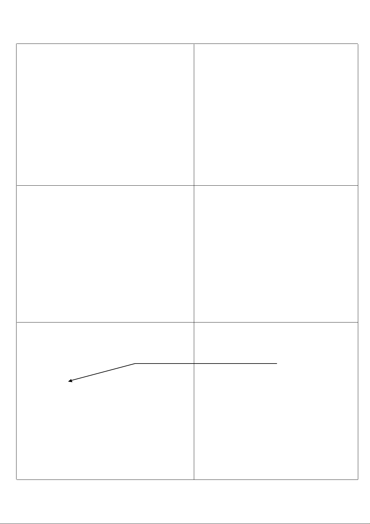
M10 x 240 section assembling rods must be connected to
assembling ears and foot in balance and middle section must
be connected to back section.
*** Section assembling rods are for the assembling of
the sections. They are not for preventing leakages.
Same process must be replied according to the capacity
( middle section quantity ) of the boiler. Middle section
assemblies must be done in the same way.
After middle sections assembling same process must be
applied to front section for front section assembly.
Sayfa - 4
*** The rope which is installed to last middle section
smoke leakproof channel ( the middle section before
the front section) can not be installed to the channel
between 2nd and 3rd passes.
Boiler assembly rods must be connected after all sections
assembly process is finished.
4 pcs of assembling rods must be connected to the boiler,
stabilization holes which are on front and back sections of
the boilers. Nuts and bolts must be installed in cross ways
Screwing torque : 6 kgm
*** Section assembly rods must not be taken off .
These rods will be used on cabin assembly.
Expansion Springs Assembly :
4 pcs of boiler assembly rods in the front and nuts must be
taken off one by one and expansion springs must be connected in cross way. Than nuts and bolts must be screwed again.
For screwing torque control : 3 kgm
*** Expansion springs assembly must be done one by
one and in cross ways.
Boiler assembly expansion springs assembly must be done
as seen in the figure on top ; with nuts and bolts.
Spring joints distance must be approximately 0,5 mm.
After section assembly and boiler assembly rods assembly
boiler back chimney door and water input - output adaptors
must be installed.
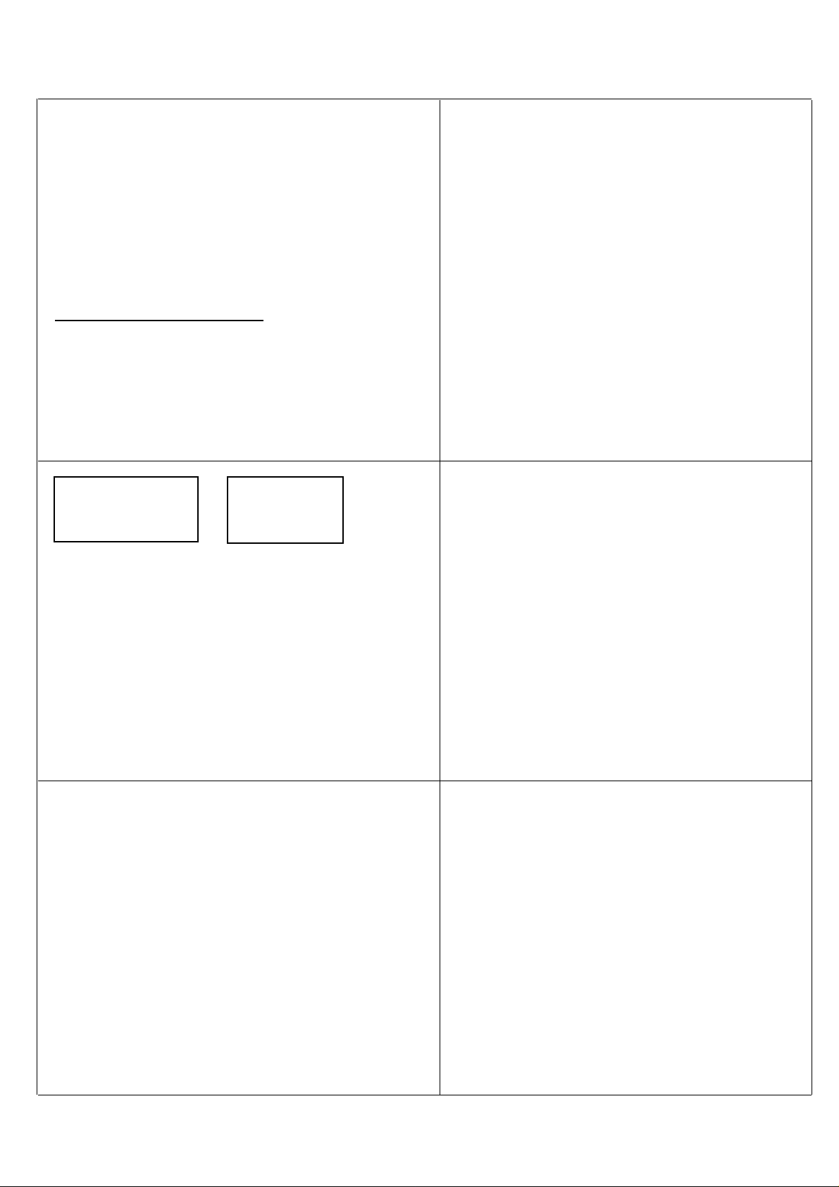
Boiler back cihmney door must be installed and must be
screwed with 4 pcs of M12 x 95 rods for preventing the
leakage.
Water input- output adaptors must be installed by connecting
washers and, must be screwed with 4 pieces of bolts for
preventing leakage.
*** Water input adaptor must be installed (adaptor at
bottom ) as 1 1/2'' releasing valve shows bottom or
side ways.
*** Water input adaptor must be installed with connect ing washer, pipe with flange,washer and adaptor in
a raw.
*** 1 1/2'' output of output adaptor must show top or
side ways.
Sayfa - 5
and must be screwed in balance.
After installation of boiler input and output adaptors, boiler
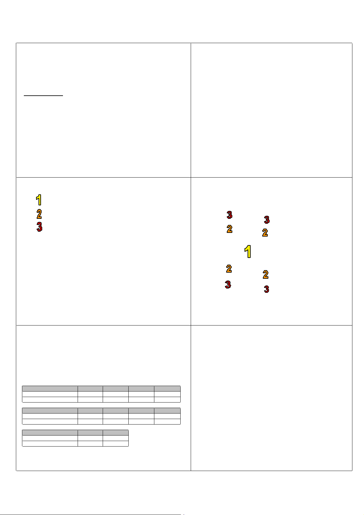
Boiler Burning Gas ( 1. Pass )
Boiler Burning Gas ( 2. Pass )
Boiler Burning Gas ( 3. Pass )
1. Install the flame delayer turbulators to the channels as seen
on table.
*** Small turbulators must be installed to 2nd passes and
2 pieces for each .Big turbulators must be installed to
3rd passes.
Turbulators must be installed to passage channels from front
section.
Boiler Model ОМ-06 ОМ-07 ОМ-08 ОМ-09
Second pass 1+1+1+1 1+1+1+1 1+1+1+1 1+1+1+1
Third pass 1+1+1+1 1+1+1+1 1+1+1+1 1+1+1+1
*** Turbulators must be connected through the middle of
the front section.
Sayfa - 6
must be tested for leakage by filling water inside without
connecting the front burner door ,for 10 minutes under
9 bars pressure .
Test Result :
If any leakage is spotted boiler must be repaired by exploring
the spot. If there are no leakages,flame delayer turbulators
assembly process must be started.
Table - 1 Flame Delayer Turbulator Installation Table :
Boiler Model ОМ -10 ОМ-11 ОМ-12 ОМ-13
Second pass 1+1+1+1 1+1+1+1 1+1+1+1 1+1+1+1
Third pass 1+1+1+1 1+1+1+1 1+1+1+1 None
Boiler Model ОМ-14 OМ 15-16
Second pass 1+1+1+1 None
Third pass None None
After the installation of the turbulators to the passes boiler
burner door must be connected to front section.
4 hinges which are conneced to front section, must be
connected to the hinge arms on the burner door.
Connect M10 x 80 mm hinge bolts according to your desire
for opening side according to plumbing connections and
boiler room.
After connecting bolts 4 pcs M16 nuts and pins must be
connected and screwed in balance.
*** There must be no gap between the burner door and
front section for preventing smoke leakage.
After body assembly and leakage tests blakite® - which is
given with assembling parts - must be applied between the
sections for preventing smoke leakage.
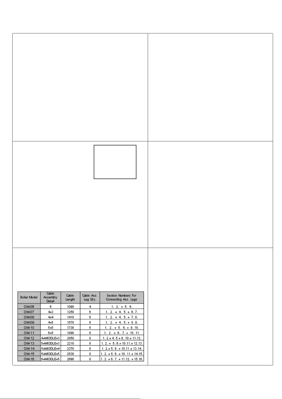
For cabin sheets installation cabin assembly legs must be
connected to rods on the boiler legs.
Cabin sheet assembly legs must be connected to the rods
which we have used for sections connections,as shown in
the picture. Than the rods must be screwed.
Table - 2 Assembling Leg Table :
Sayfa - 7

*** Selection of section legs and cabin sheet assembly
legs is shown in table 2.
After connection of cabin sheet assembly legs in both sides of
the boiler body, cabin sheet assembly ears on top of the boiler
body must be connected to their places.
*** If there are no assembling rods on the section which
assembly legs and ears
will be connected, these
rods can be taken from
other sections .
Cabin sheet assembly ears must be
connected to the assembly rods on top
side as seen in the picture. Than, nuts
must be screwed with a light force for
holding the piece.
Table - 3 Assembly Ear Table :
Sayfa - 8
After the installation of the cabin sheet assembling legs
and ears , body insulation and cabin sheets must be installed
on the body.

8 cm body isolation must be prepared according to boiler
dimensions and installed on the boiler body.
Body insulation must be cut for opening thermostat socket.
Same process must be applied to additional right and left
cabin sheets for their installation to the boiler body.
Sayfa - 9
Isolation must be cut around assembling ears connection
points.
Isolation must be connected with a stainless steel wire from 2
points to the body for stabilization.
First the holes on the side cabin sheets must be connected to
the pins on the assembly legs and than must be connected to
cabin sheet assembly ears with M8 x 20 bolts as seen in the
picture.

After installation of side cabins control panel must be connected
on to the front top cabin sheet.
Sayfa - 10

There are three holes on the front cabin sheet. Thermocouples
( sensors) of the control panel ( thermostat,safety thermostat,
thermometer ) must be passed through the middle hole.
Control panel must be stabilized to the holes on right and left.
After installing sensors edges inside the socket segment
must be plugged for preventing the sensor edges to move out.
After these processes pins on the top cabin must be connected
to segments on side cabins.
Extra top cabin must be installed by connecting to the segments
on side cabins.
After side and top cabin sheet assembly, back cabin sheet
must be installed.
Sayfa - 11
*** Oil which is given with the assembling parts,must be
filled to thermostat hole for increasing the sensitivity
of the sensors.

Back cabin sheet isolation must be installed and back sheet
Than the boiler is ready for burner installation, system and
chimney connections.
*** Burner installation, chimney and system connec tions must be done according to the standards and
in attention with specifications in operation and
maintenance manuals and by authorized technicians.
Sayfa - 12
must be connected to the side cabins ( as the open side
shows upside ) with cabin connection screws as shown in the
picture. ( 4 pcs. for right , 4 pcs. for left and 3 pcs. for the
middle connection point. )
As back cabin sheet installation completes, all cabin parts
installation is finishes.
 Loading...