

Rikon Power Tools 10-342 Operator's Manual

18” Bandsaw
10-342
Operator’s Manual
Record the serial number and date of purchase in your manual for future reference.
Serial Number: _________________________ Date of purchase: _________________________
For technical support or parts questions, email techsupport@rikontools.com or call toll free at (877)884-5167
10-342M1
4001824
www.rikontools.com

TABLE OF CONTENTS
Specications.....................................................................................................................2
Safety Instructions ........................................................................................................3 - 6
Getting To Know Your Machine .........................................................................................7
Contents of Package ....................................................................................................8 - 9
Installation .....................................................................................................9
Assembly ........................................................................................................10 - 12
Adjustments...............................................................................................................12 - 20
Operation ...................................................................................................21,22
Maintenance ......................................................................................................22,23
Wiring Diagram ................................................................................................................22
Notes ............................................................................................................................23
Troubleshooting ........................................................................................................24 - 27
Parts Diagrams & Parts Lists ..................................................................................28 - 37
Accessories ....................................................................................................38
Warranty ..........................................................................................................................39
SPECIFICATIONS
Motor ..................................................................................... 2 HP, TEFC
Motor Speed (no load)............................................................ 1,720 RPM
Volts ................................................................................................ 220 V
Amps, Hertz ..........................................................................7.5 A, 60 Hz
Blade Length ..................................................................153” (3,886 mm)
Blade Width ...................................................1/4” - 1-3/8” (6.35 - 35 mm)
Blade Speed ...................................................3,280 ft/min (1,000 m/min)
Table Size (W x D) .............................. 21-1/2” x 15-3/4” (546 x 400 mm)
Table Side Extension Size (W x D)........ 4-3/8” x 15-3/4” (110 x 400 mm)
Table Tilt ................................................................... Left -100 , Right 45
Maximum Cutting Width (throat) ...................................17-1/2” (445 mm)
Maximum Cutting Depth (height) ....................................... 13” (330 mm)
Table Height ..................................................................35-1/2” (902 mm)
Fence Height ........................................................................ 6” (152 mm)
Fence Length ............................................................... 18-3/4” (475 mm)
Miter Gauge T-Slots (2) ............................... 3/4” x 3/8” (19.05 x 9.5 mm)
Dust Ports (2) ....................................................... 4” Diameter (100 mm)
Base Size ............. 29-11/32” x 18-1/8” x 2-7/16” (745 x 460 x 62.5 mm)
Overall Height ............................................................ 72-7/8” (1850 mm)
Overall Size (WxDxH) ...... 38-1/2”x29-1/8”x72-7/8” (976x740x1850 mm)
Net Weight ..................................................................... 328 lbs (149 kg)
°
NOTE: The specications, photographs, drawings and information in this manual represent the current model when the
manual was prepared. Changes and improvements may be made at any time, with no obligation on the part of Rikon
Power Tools, Inc. to modify previously delivered units. Reasonable care has been taken to ensure that the information in
this manual is correct, to provide you with the guidelines for the proper safety, assembly and operation of this machine.
2

SAFETY INSTRUCTIONS
IMPORTANT! Safety is the single most important consideration in the operation of this equipment. The following
instructions must be followed at all times. Failure to follow all instructions listed below may result in electric shock, re,
and/or serious personal injury.
There are certain applications for which this tool was designed. We strongly recommend that this tool not be modied and/
or used for any other application other than that for which it was designed. If you have any questions about its application,
do not use the tool until you have contacted us and we have advised you.
SAFETY SYMBOLS
SAFETY ALERT SYMBOL: Indicates DANGER, WARNING, or CAUTION. This symbol may be used in
conjunction with other symbols or pictographs.
Indicates an imminently hazardous situation, which, if not avoided, could result in death or serious injury.
Indicates a potentially hazardous situation, which, if not avoided, could result in death or serious injury.
Indicates a potentially hazardous situation, which, if not avoided, could result in minor or moderate injury.
NOTICE: Shown without Safety Alert Symbol indicates a situation that may result in property damage.
GENERAL SAFETY
KNOW YOUR POWER TOOL. Read the owner’s manual
carefully. Learn the tool’s applications, work capabilities,
and its specic potential hazards.
BEFORE USING YOUR MACHINE
To avoid serious injury and damage to the tool, read and
follow all of the Safety and Operating Instructions before
operating the machine.
1. Some dust created by using power tools contains
chemicals known to the State of California to cause cancer,
birth defects, or other reproductive harm.
Some examples of these chemicals are:
• Lead from lead-based paints.
• Crystalline silica from bricks, cement, and other
• masonry products.
• Arsenic and chromium from
chemically treated lumber.
Your risk from these exposures varies, depending on how
often you do this type of work. To reduce your exposure to
these chemicals: work in a well ventilated area and work
with approved safety equipment, such as those dust masks
that are specially designed to lter out microscopic
particles.
2. READ the entire Owner’s Manual. LEARN how to use
the tool for its intended applications.
3. GROUND ALL TOOLS. If the tool is supplied with a 3
prong plug, it must be plugged into a 3-contact electrical
receptacle. The 3rd prong is used to ground the tool and
provide protection against accidental electric shock. DO
NOT remove the 3rd prong. See Grounding Instructions on
the following pages.
4. AVOID A DANGEROUS WORKING ENVIRONMENT.
DO NOT use electrical tools in a damp environment or
expose them to rain.
5. DO NOT use electrical tools in the presence of
ammable liquids or gasses.
6. ALWAYS keep the work area clean, well lit, and
organized. DO NOT work in an environment with oor
surfaces that are slippery from debris, grease, and wax.
7. KEEP VISITORS AND CHILDREN AWAY. DO NOT
permit people to be in the immediate work area, especially
when the electrical tool is operating.
8. DO NOT FORCE THE TOOL to perform an operation
for which it was not designed. It will do a safer and higher
quality job by only performing operations for which the tool
was intended.
9. WEAR PROPER CLOTHING. DO NOT wear loose
clothing, gloves, neckties, or jewelry. These items can get
caught in the machine during operations and pull the
operator into the moving parts. The user must wear a
protective cover on their hair, if the hair is long, to prevent it
from contacting any moving parts.
10. CHILDPROOF THE WORKSHOP AREA by removing
switch keys, unplugging tools from the electrical
receptacles, and using padlocks.
11. ALWAYS UNPLUG THE TOOL FROM THE
ELECTRICAL RECEPTACLE when making adjustments,
changing parts or performing any maintenance.
3

SAFETY INSTRUCTIONS
12. KEEP PROTECTIVE GUARDS IN PLACE AND IN
WORKING ORDER.
13. AVOID ACCIDENTAL STARTING. Make sure that the
power switch is in the “OFF” position before plugging in the
power cord to the electrical receptacle.
14. REMOVE ALL MAINTENANCE TOOLS from the
immediate area prior to turning “ON” the machine.
15. USE ONLY RECOMMENDED ACCESSORIES. Use
of incorrect or improper accessories could cause serious
injury to the operator and cause damage to the tool. If in
doubt, check the instruction manual that comes with that
particular accessory.
16. NEVER LEAVE A RUNNING TOOL UNATTENDED.
Turn the power switch to the “OFF” position. DO NOT
leave the tool until it has come to a complete stop.
17. DO NOT STAND ON A TOOL. Serious injury could
result if the tool tips over, or you accidentally contact the
tool.
18. DO NOT store anything above or near the tool where
anyone might try to stand on the tool to reach it.
19. MAINTAIN YOUR BALANCE. DO NOT extend
yourself over the tool. Wear oil resistant rubber soled
shoes. Keep oor clear of debris, grease, and wax.
20. MAINTAIN TOOLS WITH CARE. Always keep tools
clean and in good working order. Keep all blades and tool
bits sharp, dress grinding wheels and change other
abrasive accessories when worn.
21. EACH AND EVERY TIME, CHECK FOR DAMAGED
PARTS PRIOR TO USING THE TOOL. Carefully check all
guards to see that they operate properly, are not damaged,
and perform their intended functions. Check for alignment,
binding or breaking of moving parts. A guard or other part
that is damaged should be immediately repaired or
replaced.
22. DO NOT OPERATE TOOL WHILE TIRED, OR
UNDER THE INFLUENCE OF DRUGS, MEDICATION
OR ALCOHOL.
23. SECURE ALL WORK. Use clamps or jigs to secure
the workpiece. This is safer than attempting to hold the
workpiece with your hands.
24. STAY ALERT, WATCH WHAT YOU ARE DOING,
AND USE COMMON SENSE WHEN OPERATING A
POWER TOOL.
A moment of inattention while operating power tools may
result in serious personal injury.
25. ALWAYS WEAR A DUST MASK TO PREVENT
INHALING DANGEROUS DUST OR AIRBORNE
PARTICLES, including wood dust, crystalline silica dust
and asbestos dust. Direct particles away from face and
body. Always operate tool in well ventilated area and
provide for proper dust removal. Use dust collection
system wherever possible. Exposure to the dust may cause
serious and permanent respiratory or other injury, including silicosis (a serious lung disease), cancer, and death.
Avoid breathing the dust, and avoid prolonged contact with
dust. Allowing dust to get into your mouth or eyes, or lay
on your skin may promote absorption of harmful material.
Always use properly tting NIOSH/OSHA approved respiratory protection appropriate for the dust exposure, and wash
exposed areas with soap and water.
26. USE A PROPER EXTENSION CORD IN GOOD
CONDITION. When using an extension cord, be sure to
use one heavy enough to carry the current your product
will draw. The table on the following page shows the correct size to use depending on cord length and nameplate
amperage rating. If in doubt, use the next heavier gauge.
The smaller the gauge number, the larger diameter of the
extension cord. If in doubt of the proper size of an extension cord, use a shorter and thicker cord. An undersized
cord will cause a drop in line voltage resulting in a loss of
power and overheating.
USE ONLY A 3-WIRE EXTENSION CORD THAT HAS
A 3-PRONG GROUNDING PLUG AND A 3-POLE
RECEPTACLE THAT ACCEPTS THE TOOL’S PLUG.
27. ADDITIONAL INFORMATION regarding the safe and
proper operation of this product is available from:
• Power Tool Institute
1300 Summer Avenue
Cleveland, OH 44115-2851
www.powertoolinstitute.org
• National Safety Council
1121 Spring Lake Drive
Itasca, IL 60143-3201
www.nsc.org
• American National Standards Institute
25 West 43rd Street, 4th Floor
New York, NY 10036
www.ansi.org
• ANSI 01.1 Safety Requirements for
Woodworking Machines and the
U.S. Department of Labor regulations
www.osha.gov
28. SAVE THESE INSTRUCTIONS. Refer to them
frequently and use them to instruct others.
4

SAFETY INSTRUCTIONS
ELECTRICAL SAFETY
THIS TOOL REQUIRES THE
INSTALLATION OF A 220V PLUG (NOT INCLUDED),
AND MUST BE GROUNDED WHILE IN USE TO
PROTECT THE OPERATOR FROM ELECTRIC SHOCK.
IN THE EVENT OF A MALFUNCTION OR BREAKDOWN,
grounding provides the path of least resistance for electric
current and reduces the risk of electric shock. This tool
is equipped with an electric cord that has an equipment
grounding conductor and requires a grounding plug (not
included). The plug MUST be plugged into a matching
electrical receptacle that is properly installed and grounded
in accordance with ALL local codes and ordinances.
DO NOT MODIFY ANY PLUG. If it will not t the electrical
receptacle, have the proper electrical receptacle installed
by a qualied electrician.
IMPROPER ELECTRICAL CONNECTION of the
equipment grounding conductor can result in risk of
electric shock. The conductor with the green insulation
(with or without yellow stripes) is the equipment grounding
conductor. DO NOT connect the equipment grounding
conductor to a live terminal if repair or replacement of the
electric cord or plug is necessary.
CHECK with a qualied electrician or service personnel if
you do not completely understand the grounding
instructions, or if you are not sure the tool is properly
grounded when installing or replacing a plug.
REPLACE A DAMAGED OR WORN CORD
IMMEDIATELY.
This tool is intended for use on a circuit that has a 220
volt electrical receptacle. FIGURE 1 shows the type of the
220V, 4-wire electrical plug and electrical receptacle that
has a grounding conductor that is required.
Samples of 220 volt plugs required for this machine.
EXTENSION CORDS
USE OF AN EXTENSION CORD
WITH THIS MACHINE IS NOT RECOMMENDED. FOR
BEST POWER AND SAFETY, PLUG THE MACHINE
DIRECTLY INTO A DEDICATED GROUNDED ELECTRICAL OUTLET THAT IS WITHIN THE SUPPLIED CORD
LENGTH OF THE MACHINE.
IF AN EXTENSION CORD NEEDS TO BE USED, IT
SHOULD ONLY BE FOR LIMITED OPERATION OF THE
MACHINE. THE EXTENSION CORD SHOULD BE AS
SHORT AS POSSIBLE IN LENGTH, AND HAVE A
MINIMUM GAUGE SIZE OF 14AWG.
USE ONLY A 4-WIRE EXTENSION CORD THAT HAS
THE PROPER TYPE OF A 4-PRONG GROUNDING
PLUG THAT MATCHES THE MACHINE'S 4-PRONG
PLUG AND ALSO THE 4-POLE RECEPTACLE THAT
ACCEPTS THE TOOL’S PLUG. *
Check extension cords before each
use. If damaged replace immediately. Never use a tool
with a damaged cord, since touching the damaged
area could cause electrical shock, resulting in serious
injury.
Use a proper extension cord. Only use cords listed by
Underwriters Laboratories (UL). Other extension cords can
cause a drop in line voltage, resulting in a loss of power
and overheating of tool. When operating a power tool
outdoors, use an outdoor extension cord marked “W-A” or
“W”. These cords are rated for outdoor use and reduce the
risk of electric shock.
Keep the extension cord clear
of the working area. Position the cord so that it will
not get caught on lumber, tools or other obstructions
while you are working with a power tool.
* Canadian electrical codes require extension cords to
be certied SJT type or better.
** The use of an adapter in Canada is not acceptable.
Consult a qualied electrician if the distance of the
machine to the electrical panel is greater than 30 feet.
Figure 1
THIS SYMBOL DESIGNATES THAT
THIS TOOL IS LISTED BY THE
INTERTEK TESTING SERVICES,
TO UNITED STATES AND
CANADIAN STANDARDS.
5

SAFETY INSTRUCTIONS
SPECIFIC SAFETY INSTRUCTIONS FOR BAND SAWS
This machine is intended for the cutting of natural, solid woods, composite materials, plastics and non-ferrus
metals. The permissible workpiece dimensions must be observed (see Technical Specification). Any other
use not as specified, including modification of the machine or use of parts not tested and approved by the
equipment manufacturer, can cause unforeseen damage and invalidate the warranty.
ATTENTION:
Therefore, the user must be aware that wood working machines are dangerous if not used with care and all
safety precautions are adhered to.
1. Do not operate this machine until you have read all of the following instructions.
2. If you are not familiar with the operation of the machine, obtain assistance from a qualied person.
3. Always wear approved, safety protective eye wear and hearing protection when operating this machine.
4. Always wear a dust mask and use adequate dust collection and proper ventilation.
5. Adjust the upper guides about 1/8” to 1/4” above the material being cut.
6. Check for proper blade size and type for the thickness and type of material being cut.
7. Make sure that the blade tension and blade tracking are properly adjusted.
8. Always keep hands and ngers away from the blade.
9. Make “relief” cuts before cutting curves to eliminate blade binding.
10. Always hold material rmly, resting at on the table and feed it into the blade at a moderate speed.
11. Never attempt to saw stock that does not have a at surface, unless a suitable support is used.
12. When cutting small work pieces, always use a push stick, holding jig or other device to keep your hands
safely away from the blade. Use ‘Zero Clearance Inserts’ to prevent small pieces from becoming
jammed in the table insert or lower blade guides.
13. Always allow the bandsaw blade to stop before removing scrap pieces from the table.
14. Do not remove jammed pieces from the saw until the machine and blade has stopped. Unplug the
bandsaw from the power source, and then remove the jammed work piece.
15. Always turn off the machine if the material is to be backed out of an uncompleted cut.
16. Use extra supports (roller stands, saw horses, tables etc.) for any work pieces large enough to tip
when not held down to the table top surface.
17. Always turn off and unplug the machine when changing blades or servicing the machine.
18. Release blade tension when the saw will not be used for a long period of time.
19. Remove material or debris from the work area. Keep work area neat and clean.
Use of this band saw still presents risks that cannot be eliminated by the manufacturer.
SAVE THESE INSTRUCTIONS.
WARNING: Some dust created by power sanding, sawing, grinding, drilling, and other construction activities
contains chemicals known to the State of California to cause cancer and birth defects or other reproductive
harm. Your risk from exposure to these chemicals varies, depending on how often you do this type of work.
To reduce your exposure, work in a well-ventilated area and with approved safety equipment, such as dust
masks that are specially designed to lter out microscopic particles.
For more detailed information about California Proposition 65 log onto www.rikontools.com.
This owner’s manual is not a teaching aid. Use of this owner’s manual is intended to
show assembly, adjustments, and general use.
Refer to them often.
California Proposition 65 Warning
6

GETTING TO KNOW YOUR MACHINE
F
A
B
C
D
G
M
P
Q
H
H
R
O
I
S
T
J
U
K
N
V
L
G
W
X
G
*
*
E
* 10-342 BANDSAW SHOWN WITH OPTIONAL MOBILITY KIT BASE ATTACHED (13-345). OPTIONAL KIT’S TOW BAR ALSO NOT SHOWN.
A. Tension Indicator Window
B. Blade Tension Hand Wheel
C. On/Off Switch
D. Rip Fence, Rail & Re-saw Bar
E. Base
F. Blade Tracking Window
G. Door Lock Knob
H. Guide Post Rise/Fall Handle
I. Blade Guard
J. Upper Blade Guides
K. Work Table
L. Lower Blade Guides & Blade Guard
7
M. 4” Dust Port
N. Table Tilt Wheel & Locking Handle
O. Guide Post Lock Knob
P. Blade Tracking Knob
Q. Push Stick & Hanger Bolt
R. Blade Tension Quick Release Lever
S. Tool Holder
T. Hanger Bolts for Tow Bar (optional)
U. Electrical Outlet 110V
V. Motor Adjusting Rod & Nut
W. Motor & Wiring Box
X. Lower Wheel Adjustment Bolts
M

CONTENTS OF PACKAGE
Model 10-342 18” Bandsaw is shipped complete in one box.
Unpacking, Checking Contents & Clean-up
1. Carefully remove all contents from the shipping carton. Compare the contents with the list of contents to
make sure that all of the items are accounted for, before discarding any packing material. Place parts on a
protected surface for easy identication and assembly. If any parts are missing or broken, please call RIKON
Customer Service (877- 884-5167) as soon as possible for replacements. DO NOT turn your machine ON if
any of these items are missing. You may cause injury to yourself or damage to the machine.
2. Report any shipping damage to your local distributor.
3. With the help of another person, carefully lift the Bandsaw from the packaging and place it on a level oor.
4. Clean all rust protected surfaces with ordinary house hold type grease or spot remover. Do not use;
gasoline, paint thinner, mineral spirits, etc. These may damage painted surfaces.
5. Apply a coat of paste wax to the table to prevent rust. Wipe all parts thoroughly with a clean dry cloth. Be
careful, as the pre-installed bandsaw blade has sharp teeth and may cause injury if touched.
6. Set packing material and shipping carton aside. Do not discard until the machine has been set up and is
running properly.
A
TABLE OF LOOSE PARTS
A. Bandsaw Frame Assembly
B. Table with Extension and Blade Insert
C. Rip Fence Front Rail and Hardware
D. Leveling Pin and Lanyard
E. Table Leveling Bolt and Nut
F. Table Mounting Bolts and Washers
G. Manual and Warranty Card - not shown
B
F
E
D
C
Link to RIKON website,
10-342 Product Page and
ASSEMBLY VIDEO
8
CONTENTS OF PACKAGE
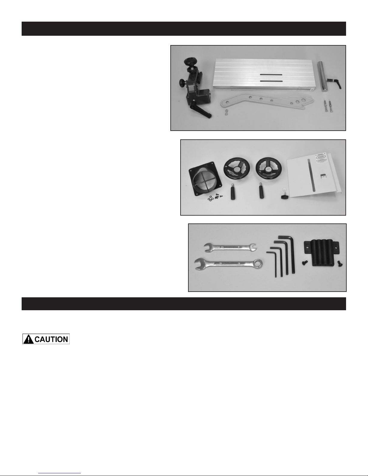
TABLE OF LOOSE PARTS continued
Rip Fence Assembly & Parts:
A. Rip Fence
B. Rip Fence Carrier Assembly
C. Push Stick and Mounting Bolt and Nut
D. Hanger Bolts for Tow Bar (accessory item)
E. Re-saw Bar Assembly
Parts for Assembly on Frame:
F. Dust Port & Mounting Screws
G. Handwheels (2)
H. Handles for Handwheels (2)
I. Lower Blade Guard and Knob
Tools and Tool Holder:
J. Wrenches: 10, 13 mm
K. Hex Wrenches; 3, 4, 5, 6 mm
L. Tool Holder and Mounting Screws
B
A
E
C
D
G
F
H
I
Additional Tools required - not supplied
#2 Phillips Screwdriver
16mm or an Adjustable Wrench
INSTALLATION
MOVING & INSTALLING THE BANDSAW
The bandsaw is heavy - over 300
lbs! It is best to assemble the machine near the
area where it will eventually reside.
When moving or positioning an assembled
bandsaw, DO NOT use the table or upper blade
guard assemblies as this may damage the
machine. Move the bandsaw by grasping the
support column and lower frame which are all
welded together for rigidity. The bandsaw can
also be moved by laying it down on the back/left
side of the column so that the table assembly is
not compromised.
J
L
K
2. Position the machine on a solid, level foundation
that is located in an area that has ample space in
front, right side and in back of the bandsaw for cutting
large or long material.
For best power and safety, the bandsaw should be
plugged directly into a dedicated grounded electrical
outlet that is within the supplied cord length of
the machine. The use of an extension cord is not
recommended.
3. Align the machine so that during use, the material
being cut will not face aisles, doorways, or other work
areas that bystanders may be in. Do not locate or use
the machine in damp or wet conditions.
1. Carefully remove the machine from the shipping
carton. See above instructions on handling the saw.
4. Once in place in your shop, level the machine with
spacers, and secure it to the floor with lag screws
(not supplied) using the 4 holes in the saw’s base.
9
ASSEMBLY
THE MACHINE MUST NOT BE
PLUGGED IN AND THE POWER SWITCH MUST BE IN
THE OFF POSITION UNTIL ASSEMBLY IS COMPLETE.
NOTE: Parts referenced throughout the manual
refer to the different sheets and key numbers of the
Parts Diagrams and Parts Lists on pages 28 to 37.
Example: (#1A) refers to Part #1 on Sheet A.
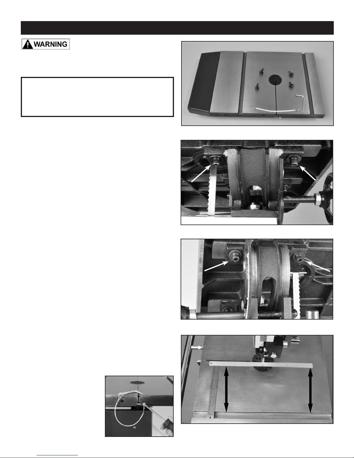
TABLE ASSEMBLY
1. Mount the table (Fig. 1) in place on the trunnion
with the assistance of another person. The table is
heavy! Do this from the rear of the machine, so that it
is easier to t the pre-installed blade through the slot
in the table.
2. Attach the table to the trunnion with the four Hex
Socket Cap Screws, Spring Washers and Washers
(Parts #13B, 12B, 11B). Install two bolts to the right
of the blade, hand tightened only. Fig. 2. Then tip the
table to 45 degrees and install the two bolts to the left
of the blade. Fig. 3. DO NOT fully tighten the bolts at
this time. Return the table to the horizontal position.
NOTE: Before nally secured in position, the table can
be slightly moved, left and right. Check to make sure
that the table’s miter gauge slot is parallel to the side
of the saw blade. This will provide a true cut when
ripping stock. Set a thin metal ruler against the side
of the saw blade. Make sure that it is not touching
the saw’s teeth, which can angle the ruler. Measure
the distance from one end of the ruler to the miter
gauge slot. FIG. 4. Then measure the same distance
from the other end of the ruler to the miter gauge slot.
Compare these two measurements and angle the
table as necessary until the distances are the same.
FIGURE 1
FIGURE 2
FIGURE 3
3. Once the table is aligned parallel to blade, tighten
all four of the installed bolts to secure the table in
place.
4. Attach the Table Leveling
Pin’s Lanyard (Part #5B) to
the front of the table with
the supplied Phillips Screw
and Washer. This metal pin
keeps the two sides of the
table level at the slot area.
FIGURE 4
10
ASSEMBLY
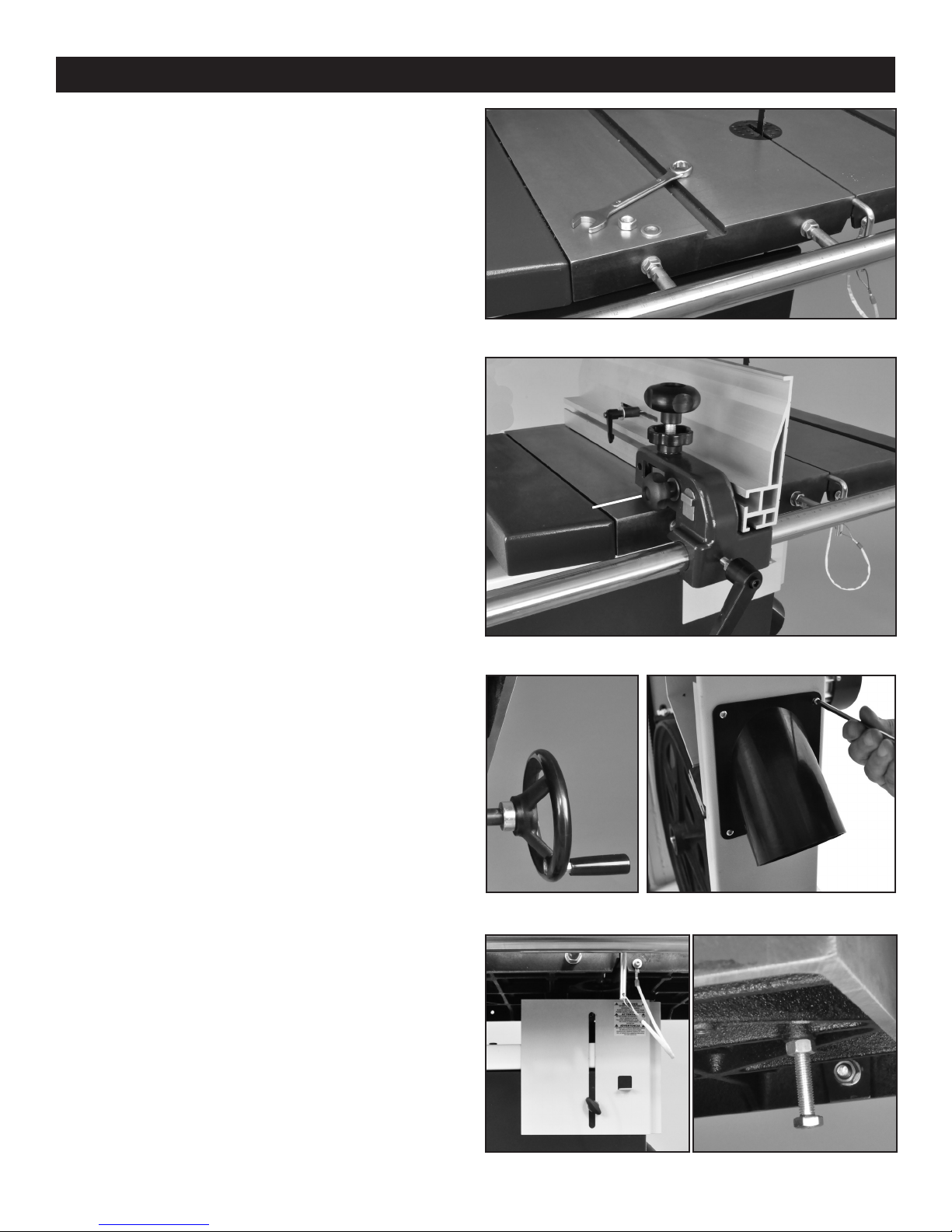
RIP FENCE ASSEMBLY
1. Mount the fence Guide Rail (#12E) onto the front
table edge with the two fence bar Nuts and Washers
(#14E, 5E) Fig. 5. Position the bar so that it is parallel
with the table surface, and equal distance out from the
front edge of the table when measured at both left and
right front edges of the table.
2. Slide the Fence Carrier Assembly (#9E) onto the
fence’s guide rail. Fig. 6.
3. Slide the Rip Fence (#18E) onto the fence carrier,
and lock it in place by tightening the fence lock Knob
(#7E) which is located on the carrier, opposite side to
the fence. Fig. 6, A.
4. With the front Locking Handle (#10E, Fig. 6,B)
secure the fence on the rail so that it does not
move during the rest of the assembly process. Final
adjustments to the fence are covered on pages 18 to
20. Information on the re-saw bar is on page 21.
INSTALL THE HAND WHEELS
1. Attach the small Handle (#25B) to the large
Handwheel (#24B) that tilts the table. Then install this
handwheel onto the Gear Shaft (#23B) extending out
from the trunnion at the back of the machine. Fig. 7A.
2. Attach the second small Handle to the Handwheel
(#38C) that has been pre-installed at the upper right
side of the saw frame. This wheel raises and lowers
the blade guard.
INSTALL THE 4” DUST PORT
FIGURE 5
A
B
FIGURE 6
Mount the 4” Dust Port (#53A) under the table on the
right side of the saw frame with four pan head screws
and at washers (#51A, 52A) using a Phillips screw
driver. Fig. 7B.
INSTALL THE LOWER BLADE GUARD
Attach the Blade Guard (#19A) to the front of the
lower door with the Handle and Washer (#17A, 18A).
Slide the guard up to protect the lower guides during
use, and slide the guard down when adjusting the
lower guides is needed. Fig. 8A.
INSTALL THE 90° TABLE STOP
1. Tilt the table to gain access to its underside.
2. Thread the Hex Screw (#9B) and Nut (#8B) to the
bottom of the table in the pre-bored and tapped hole.
Fig. 8B. Setting the table to 90° to the blade will be
done later on pages 12 and 13.
A FIGURE 7 B
A FIGURE 8 B
11
ASSEMBLY
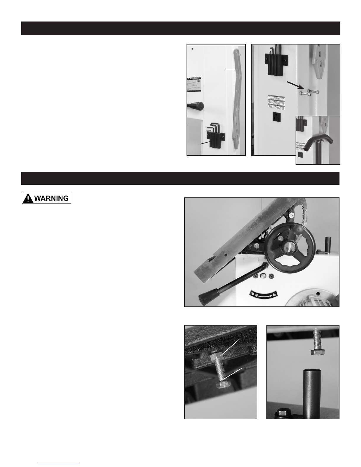
INSTALL THE TOOL HOLDER
Assemble the Tool Holder (#68A) to the column rear
with two Phillips Screws. Fig. 9, A.
Handy storage for the Hex Wrenches (3, 4, 5, 6mm).
INSTALL THE PUSH STICK HOLDER
Assemble the Push Stick Hanger Bolt (#4A) to the
column’s left side with a 5mm hex wrench. Handy
storage for the push stick when not in use. FIG. 9, B.
INSTALL THE TOW BAR HOLDER
B
C
Two bolts (#4A) are included to store the tow bar
included with the optional Mobility Kit #13-345. Screw
the bolts into the column’s left side. Fig. 10, C.
ADJUSTMENTS
THE MACHINE MUST NOT BE
PLUGGED IN AND THE POWER SWITCH MUST BE IN THE
OFF POSITION UNTIL ALL ADJUSTMENTS ARE COMPLETE.
TILTING THE TABLE
1. At the rear of the saw, loosen the Quick Locking
Handle (#74A) on the table trunnion by pulling it
upward. Fig.11, A.
2. Turn the table tilting Handwheel (#24B) to adjust
the table to the desired angle. Fig. 11, B. Use the
angle indicator scale (#32B) on the trunnion bracket
(#27B) to nd the desired angle, Fig. 11, C.
3. Retighten the lock handle to secure the table.
A
A
FIGURE 9
FIGURE 10
C
B
FIGURE 11
SETTING THE TABLE SQUARE TO THE SAW
BLADE’S SIDE
The table may be set at 90° to the saw blade sides
by adjusting the table stop Bolt (#9B) under the table.
The table stop bolt rests on the top of the pivoting
Stop Block (#62A).
1. First loosen the bolt’s Locking Nut (#8B) Fig. 12, A.
2. Set a square on the table and against the saw
blade’s at side. Tilt the table until the table is set exactly 90° to the blade, than lock the table in position.
3. Adjust the bolt (Fig. 12, B), up or down, until it is
in contact with the pivoting Table Angle Stop Block
(#62A) Fig. 12, C. Retighten the locking nut making sure that the table angle setting is maintained.
A
B
B
C
UNDERSIDE
OF THE TABLE
FIGURE 12
CONTINUED ON PAGE 13
12
 Loading...