


10-900
Tool-less Blade Guide System *
Retrot Kit
For RIKON 14” Bandsaws 10-324 & 10-325
Installation & User Manual
Record the date of purchase in your manual for future reference.
Date of purchase: _________________________
For technical support or parts questions, email techsupport@rikontools.com or call toll free at (877)884-5167
10-900M1a
* PATENT PENDING
www.rikontools.com

TABLE OF CONTENTS
Safety Instructions ........................................................................................................2
Contents of Package .....................................................................................................2 & 3
Assembly ...................................................................................................3 - 6
Adjustments...........................................................................................................7 - 9
Maintenance ..........................................................................................................9
Parts Diagrams & Parts Lists ..................................................................................10 - 11
SAFETY INSTRUCTIONS
1. The machine must not be plugged in and the power switch must be in the OFF position until assembly is
complete.
2. Do not install the Tool-less Blade Guide Retrot System until you have read all of the instructions.
3. Installation of this Retrot System must be done according to the following directions to correctly install
the parts, and to insure that the future operation of the machine is proper and safe.
4. Any other bandsaw use not as specified, including further modification of the machine or use of parts not
tested and approved by the equipment manufacturer, can cause unforeseen damage and invalidate the
warranty.
5. Refer to your Bandsaw’s Operation Manual for complete details on your bandsaw’s Safety Instructions,
Assembly, Adjustments and Operation.
6. If you are not familiar with the operation of the machine, obtain assistance from a qualied person.
7. Work in a clean, well lit area to keep tools and machine parts organized and safe.
SAVE THESE INSTRUCTIONS.
Store them with your Bandsaw’s Operator’s Manual for future reference.
CONTENTS OF PACKAGE
Model 10-900 Tool-less Blade Guide System Retrot Kit is shipped complete in one box.
Unpacking and Checking Contents
1. Carefully remove all contents from the shipping carton. Compare the contents with the list of contents to
make sure that all of the items are accounted for, before discarding any packing material. Place parts on a
protected surface for easy identication and assembly.
2. If any parts are missing or broken, please call RIKON Customer Service (877- 884-5167) as soon as
possible for replacements. DO NOT start assembling the Retrot Kit onto your machine, or use the bandsaw if
any of these items are missing. You may cause injury to yourself or damage to the machine.
3. Set packing material and shipping carton aside. Do not discard until the machine has been set up and is
running properly, in case a product return is necessary.
California Prop 65 WARNING: This product contains chemicals known to the State of California to cause cancer
and birth defects or other reproductive harm.
For more detailed information about California Proposition 65 log onto rikontools.com.
2

CONTENTS OF PACKAGE
TABLE OF LOOSE PARTS
A
B
C
Tools and Tool Holder:
A. Upper Blade Guide Assembly
B. Lower Blade Guide Assembly
C. Upper Blade Guard
D. Scale for Blade Guard
D
Additional Tools Required - not supplied
#2 Phillips Screwdriver
10mm Wrench or an Adjustable Wrench
NOTE: Parts referenced throughout the
instructions refer to the key numbers of
the Parts Diagrams and Parts Lists on
pages 10 and 11.
ASSEMBLY
THE MACHINE MUST NOT BE PLUGGED IN AND THE POWER SWITCH MUST BE IN
THE OFF POSITION UNTIL ASSEMBLY IS COMPLETE.
REMOVE THE BANDSAW BLADE
1. Remove the bandsaw blade that is mounted on your machine. NOTE: Refer to your bandsaw’s original
Operator’s Manual for instructions on the proper steps to safely perform this operation on your particular
machine model.
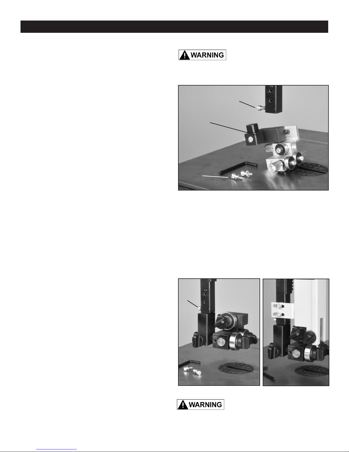
INSTALLING THE UPPER BLADE GUIDES
Remove the original, upper blade guard that
surrounds the blade above the table.
1. Lower the upper blade guides until they touch
the table. This will give the best access to the blade
guard, and make it easier to remove it from the saw
frame.
2. Remove the blade guard from the guide post by
unscrewing the two Hex Socket Cap Screws that hold
it in place. Figure 1. Save these screws as they will
be needed to install the new guard that is included
with the Retrot Kit.
CONTINUED ON PAGE 4
REMOVE
GUARD’S
2 SCREWS
ON POST
FIGURE 1
3
ASSEMBLY
INSTALLING THE UPPER BLADE GUIDES - continued
3. Once the blade guard is unscrewed, remove the
guard from the saw frame. This original guard will not
be used with the new tool-less blade guides in the Kit.
PLUGGED IN AND THE POWER SWITCH MUST BE IN THE
OFF POSITION UNTIL ALL ADJUSTMENTS ARE COMPLETE.
THE MACHINE MUST NOT BE
Remove the original, ball bearing blade guides
that were supplied on your machine.
A
4. Raise the guide post up above the table about 4
inches.
5. Remove the rear, Hex Socket Cap Screw that
holds the upper blade guide assembly to the guide
post. Figure 2, A. Save this screw as it will be used to
install the new Tool-less Guide Assembly to the guide
post.
6. Remove the originally supplied blade guide assembly from the guide post.
Install the new, Tool-less Blade Guide Assembly.
7. The new Guide Assembly comes pre-assembled and ready for installing onto your machine. Insert the new
assembly’s guide block Seat into the guide post.
ORIGINAL
BLADE
GUIDE
ASSEMBLY
SCREWS
FOR
GUARD
FIGURE 2
NOTE: The inside cavity of the post may have metal burrs left over from the original boring and threading
operations. These may require ling o in order to install the new guide block seat into the interior of the guide
post. The use of small metal les, like needle les, are recommended for removing any burrs.
8. Fasten the new Blade Guide Assembly to the guide post with the same screw (A) removed in step 5. Fig. 3A.
Install the new upper Blade Guard.
9. Lower the blade guides down to the table.
A
10. Install the new Blade Guard that is supplied with
the kit, onto the guide post. Use the same screws that
were removed in step 2, page 3. Do not fully tighten
the screws at this time. Figure 3B.
11. Before nal tightening of the screws, make sure
that the blade guard is positioned parallel, in-line with
the blade guide post. Also make sure that it will not
come in contact with the upper wheel and the door
when it is closed. Close the upper door and raise &
lower the guide post a few times to insure that the
blade guard will not rub against these saw parts.
A FIGURE 3 B
12. When positioned correctly, tighten the screws to
secure the blade guard to the guide post. Figure 3B.
Never operate the bandsaw without the blade guards in place, as serious injury may
result.
4

ASSEMBLY
INSTALLING THE LOWER BLADE GUIDES
Remove the lower drive wheel from the machine.
1. Loosen the drive belt tension and remove the drive belt from the lower wheel’s rear pulley step.
2. Remove the center Bolt and Washer that secure the lower wheel to the motor’s drive shaft.
3. Remove the lower wheel from the drive shaft. NOTE: This operation will give better access to the lower
frame interior, to allow the following installation steps to be easier.
Remove the original, lower blade guides and blade guard that are below the saw’s table.
4. If necessary, consult your bandsaw’s original Operator’s Manual for information on the parts of the lower
guide assembly, and to identify the fasteners needed to be accessed to remove the guide assembly from the
lower saw frame.
5. With the old, lower blade guide and guard assembly removed, make sure that the lower frame area and
pre-bored hole(s) is clean of any sawdust or residue
left from past saw usage. Figure 4.
Install the new, lower Tool-less Blade Guide &
Guard Assembly.
6. The new Blade Guide Assembly comes pre-assembled and ready for installing onto your machine.
Remove the Hex Socket Cap Screw and Washer that
are located under the Connecting Plate (#26).
PRE-BORED
MOUNTING
HOLE IN
FRAME
FIGURE 4
7. Position the Guide Assembly onto the lower frame
with the small alignment pin that is on the bottom of
the connecting plate, set into the pre-bored hole in the
frame. Figure 5.
* SEE ADDENDUM NOTE ON PAGE 13
NOTE: If the lower, plastic blade guard hits the underside of the table insert, the guide assembly should
be removed and the top of the guard can be carefully
cut o ONLY about 3/8” - 5/8” inches (10-16mm) with
a hack saw. DO NOT remove more than this from the
top of the guard as this will defeat the safety purpose
and regulations for the guard, and void the warranty.
ALSO, see the note on page 8, below step #4 regard-
ing the position of the guard to the rear thrust bearing.
8. Once the lower Guide Assembly is positioned on
the frame, insert the Cap Screw, removed in step 6,
up through the hole in the saw frame and back into
its threaded hole in the connecting plate. Do not fully
tighten the screw at this time. Figure 5.
9. Make sure that the lower Guide Assembly is properly aligned straight to the frame and the saw’s
trunnion, then tighten the Cap Screw to secure the
assembly in place.
CONTINUED ON PAGE 6
THE MACHINE MUST NOT BE
PLUGGED IN AND THE POWER SWITCH MUST BE IN THE
OFF POSITION UNTIL ALL ADJUSTMENTS ARE COMPLETE.
FIGURE 5
Never operate the bandsaw without the blade guards in place, as serious injury may
result.
5

ASSEMBLY
INSTALLING THE LOWER BLADE GUIDES - continued
Install the Lower Drive Wheel, Belt and Blade.
10. Reverse steps 1 to 3 above. Install the lower drive
PLUGGED IN AND THE POWER SWITCH MUST BE IN THE
OFF POSITION UNTIL ALL ADJUSTMENTS ARE COMPLETE.
THE MACHINE MUST NOT BE
wheel and drive belt onto the machine, then re-tension
the drive belt. Refer to your saw’s Owner’s Manual for instructions on setting drive belt onto the proper pulley
step for the blade speed desired.
11. Install the bandsaw blade back onto the machine. Make sure that the top and bottom guides do not come
in contact with the saw blade. Adjust the saw blade so that it tracks on the center of the wheels.
NOTE: Consult your saw’s Operators Manual for instructions on setting proper belt tension and blade tracking.
12. Once the bandsaw blade is installed, the top and bottom guide bearings can be adjusted.
INSTALLING THE GUIDE HEIGHT SCALE
The Tool-less Blade Guide System Kit includes a measuring scale that can be applied to the right side of the
upper blade guard for quick setting of the upper blade
guides for the thickness of material to be cut.
To apply the scale to the blade guard:
1. Lower the upper blade guides down until they rest
on the bandsaw table surface.
2. The scale should be positioned to the right side of
the metal blade guard with the top of the scale in line
with the underside of the frame. This is the beginning
“0” location. The scale markings should increase as
you read down the scale. Figure 6.
3. Remove the backing and attach the adhesive
backed scale to the blade guard.
4. As the blade guides are raised, their distance up
from the table can be read on the scale. So if 2” thick
wood is to be cut, you can use the scale to quickly
raise the blade guard assembly and set the upper
blade guides to 2-1/4” for this material
NOTE: The specications, photographs, drawings and in-
formation in this manual represent the current model when
the manual was prepared. Changes and improvements
may be made at any time, with no obligation on the part
of RIKON Power Tools, Inc. to modify previously delivered
units. Reasonable care has been taken to ensure that the
information in this manual is correct, to provide you with the
guidelines for the proper safety, assembly and operation of
this machine.
FIGURE 6
LINK TO RIKON’s WEBSITE
FOR INFORMATION ON
MACHINES, MANUALS,
ACCESSORIES, SERVICES
AND DISTRIBUTORS.
6

ADJUSTMENTS
ADJUSTING THE BLADE GUIDES
The Tool-less Blade Guide System features quick-
adjusting, spring loaded, ball bearing blade guides for
fast and easy setting to the blades. With the bandsaw
blade properly centered on the drive wheels, the
guide bearings can then be set. NOTE: The following
photos are representative of the Tool-less Guide
System and may not specically match your machine.
B
Upper Guides:
1. Position the right and left roller guides relatively
close to the blade. First, loosen their front Lock
Handles (Fig. 7, A). The Guide Shafts that hold the
guide bearings are spring loaded! To move the guides
towards the blade, simply push the ends of the guide
shafts (B), or use the front lock handles to pull the
guides towards the blade. Lock the guides in place.
Figure 7.
2. The guides should be approximately 1/16” behind
the gullets of the saw blade. If they need to be moved,
loosen the back Clamp Handle (Fig. 8, C) and move
the Upper Guide Block (D) that holds the guides so
that the guides are properly positioned behind the
blade gullets. Re-tighten the handle when done.
Figure 8.
3. Set both bearing guides to within 1/32” of the saw
blade - about the same thickness of a business card.
Do not set the bearing guides too close, or touch the
sides of the blade, as this will adversely aect the life
of the saw blade and bearings.
A
1/16”
C
D
FIGURE 7
FIGURE 8
G
F
E
4. Adjust the rear bearing guide (Fig. 9, E) to be
just clear of the back of the saw blade. Release the
guide’s Locking Handle (F) and move the rear guide
towards the blade by pushing the end of the Rear
Guide Shaft (G). Tighten the handle when done. Fig. 9
Lower Guides:
Adjusting the lower ball bearing guides, that are below
the table, is similar to the steps for the upper guides.
1. Position the right and left roller guides close to the
blade. Loosen the front Lock Handles (Fig. 10, A).
Move the guides towards the blade by pushing the
ends of the Guide Shafts (B), or use the front lock
handles to pull the guides towards the blade. Lock the
guides in place. Figure 10.
CONTINUED ON PAGE 8
FIGURE 9
B
A
FIGURE 10 NOTE: Blade Guard removed for photo purposes
7
B
A

ADJUSTMENTS
Adjusting the Lower Guides - continued:
2. The guides should be approximately 1/16” behind
the gullets of the saw blade. If they need to be moved,
loosen the Lever Handle (Fig. 11, A), located to the
left of the Lower Guide Block (B), and move this block
that holds the guides so that the guides are properly
positioned behind the blade gullets.
Re-tighten the lever handle when done.
3. Set both bearing guides to within 1/32” of the saw
blade - about the same thickness of a business card.
Do not set the bearing guides too close, or touch the
sides of the blade, as this will adversely aect the life
of the saw blade and bearings.
4. Adjust the rear bearing guide to be just clear of the
back of the saw blade. Release the guide’s Locking
Handle (Fig. 12, C) and move the rear guide towards
the blade by using the lock handle to pull the guide
towards the blade. Tighten the handle when done.
A
B
FIGURE 11 NOTE: Blade Guard removed for photo purposes
NOTE: Due to manufacturing tolerances in the
dierent bandsaw machine frames, the lower blade
guard might come into contact with the face of the
rear thrust bearing guide and prevent the bearing from
being set in a fully forward position. If this occurs,
remove the guard from the lower guide block (part
#34) and elongate the guard’s fastening hole about
5mm (3/16”) towards the guard’s rear edge. This
should be careful done with a utility knife, 6mm (1/4”)
split point drill bit, or rotary burr. Once the hole is
elongated, then re-attach the guard in place.
Never operate the bandsaw without the blade guards in place, as serious injury may
result.
ADJUSTING THE BLADE GUIDE & GUARD
NOTE: Before cutting, set the upper guide bearings
approximately 1/4” above the top surface of the work
piece. This will give the best blade control. Figure 13.
1. Loosen the Guidepost Lock Knob (Fig. 14A) and
turn the Guidepost Handle (Fig. 15, B) to raise or
lower the guide post/upper blade guide assembly to
the desired height.
Use the measurement scale on the right side of the
guide post for quick reference on the height of the
guide bearings above the table surface.
CONTINUED ON PAGE 9
C
FIGURE 12 NOTE: Blade Guard removed for photo purposes
Approximately
1/4”
FIGURE 13
C
A B
C
FIGURE 14
8
FIGURE 15

ADJUSTMENTS
ADJUSTING THE BLADE GUARD -
continued
2. When the guide bearings are in proper position,
re-tighten the guidepost lock knob.
NOTE: The guide post is pre-set at the factory to
aligned vertical with the bandsaw blade. If the guide
post setting ever needs slight adjustment:
3. Open the top door and lower the blade guard
all the way down to the table to access the Guide
Bracket. Figure 15, D.
4. Loosen the four Hex Bolts located at the rear of
the top frame. Fig. 14, C). This will allow the guide
post to be shifted/angled a bit left or right to correct
any positioning issues.
THE MACHINE MUST NOT BE
PLUGGED IN AND THE POWER SWITCH MUST BE IN THE
OFF POSITION UNTIL ALL ADJUSTMENTS ARE COMPLETE.
D
5. There are also four Set Screws set in the rear of
the guide bracket near the corners. If the guard post
needs to be angled slightly towards the front or back of the table, or even twisted on an angle, make the
adjustment with these screws. Figure 15.
- Advancing the top two set screws will angle the post towards the rear of the table.
- Advancing the bottom two set screws will angle the post towards the front of the table.
- Setting the two left or right screws will angle the post to the right or left.
6. When the post is adjusted vertical, tighten the four hex bolts that were loosened in step 4.
FIGURE 15
MAINTENANCE
BEFORE CLEANING OR CARRYING OUT MAINTENANCE WORK, DISCONNECT THE
MACHINE FROM THE POWER SOURCE (WALL SOCKET). NEVER USE WATER OR OTHER LIQUIDS
TO CLEAN THE MACHINE. USE A BENCH BRUSH. DO NOT USE COMPRESSED AIR NEAR BEARINGS.
REGULAR MAINTENANCE OF THE MACHINE WILL PREVENT UNNECESSARY PROBLEMS.
1. Before each use:
- Check the power cord and plug for any wear or
damage. Periodically, check the drive belt for tension
and wear.
- Check for any loose screws or hardware.
- Check the area to make sure it is clear of any misplaced tools, lumber, cleaning supplies, etc. that could
hamper the safe operation of the machine.
2. To avoid a build-up of wood dust, regularly clean
all parts of the machine using a soft cloth, brush or
compressed air. A general cleaning should be done
after every use to avoid future problems and ensure
the machine is in ready condition for the next time it is
used. Use dust collection, if possible.
3. The ball bearing blade guides are pre-lubricated,
sealed, and do not need any further care. However,
keep the guide bearings free of dust, and clean the
guide bearing assemblies frequently.
4. Keep the ventilation slots of the motor clean to
prevent it from overheating.
5. To prolong the life of the blade, when the bandsaw
is not in use for extended periods, release the blade
tension. Before reusing the bandsaw, ensure that the
blade is re-tensioned and tracking is checked.
WARNING: If blowing sawdust, wear proper eye
protection to prevent debris from blowing into eyes.
9

1
2
PARTS DIAGRAM
3
4
5
6
7
8
22
21
20
19
18
17
16
9
10 11 12 13
25 24
23
26
27
28
15
14
36
35
34
11
30 31
10
32 3329

PARTS LIST
KEY NO.
1
2
3
4
5
6
7
8
9
10
11
12
13
14
15
16
17
18
19
20
21
22
23
24
25
26
27
28
29
30
31
32
33
34
35
36
DESCRIPTION
Blade guard
Hex socket cap screw M5x12
Flat washer
Locking handle
Window
Allen at end set screws M8x10
Locking handle
Spacer
Spring
Upper guide
Locking handle
Tube
Bearing
Big washer
Guide shaft
Spring
Rear guide shaft
Bar
Seat
Hex socket cap screw M5x25
Locking handle
Scale
Hex socket cap screw M6x10
Set screw
Adjusting handle
Connecting plate
Upper guide shaft
Guide shaft
Flat washer
Tube
Bearing
Tube
Adjusting handle
Lower guide block
Guard
Flat washer
QTY.
1
3
3
1
1
3
1
1
5
1
4
3
3
3
2
1
1
1
1
1
1
1
1
1
1
1
1
2
3
2
3
1
1
1
1
2
PART NO.
1-JMBS1404051000-114X
1-M5X12GB70D1B
1-WSH5GB97D1B
1-JMBS1403050004-001S
1-JMBS1404050001
1-M8X10GB77B
1-JMBS1801052002-001S
1-JMBS1403014007
1-JMBS1403014005
1-JMBS1401051001
1-JMBS1403014006-001S
1-JMBS1403014002
1-BRG6202-2RSGB276
1-WSH8GB96D1B
1-JMBS1403014003
1-JMBS1403014008
1-JMBS1403014004
1-JMBS1401051002
1-JMBS1404050003
1-M5X25GB70D1B
1-JMBS1403050003-001S
1-JMBS1401050003
1-M6X10GB70D1B
1-M6X10GB77B
1-KTSB-1-B-M6X50X10
1-JMBS1404010003
1-JMBS1404013003
1-JMBS1404013002
1-WSH8GB97D1B
1-JMBS1404013004
1-BRG6001-2RSGB276
1-JMBS1404013005
1-KTSB-1-B-M6X50X25
1-JMBS1404013001
1-JMBS1404010004-001S
1-WSH6GB97D1B
NOTE: Please reference the Manufacturer’s Part Number when calling for Replacement Parts.
For Parts under Warranty, the Serial Number of your machine is required.
11

10-900
Tool-less Blade Guide System *
Retrot Kit
For RIKON 14” Bandsaws 10-324 & 10-325
For more information:
16 Progress Road
Billerica, MA 01821
877-884-5167 / 978-528-5380
* PATENT PENDING
techsupport@rikontools.com
10-900M1a
www.rikontools.com

RIKON #10-900 TOOL-LESS BLADE GUIDE SYSTEM RETROFIT KIT
INSTRUCTIONS ADDENDUM
Addendum Notes to page 5 of the #10-900 Instructions – INSTALLING THE LOWER BLADE GUIDES
Reference Instruction’s Step 7 and Figures 4 & 5.
On older models of the 10-325 Bandsaws, the pre-bored mounting hole in the frame (Figure 4) may
not be an oval shape to accept both connecting Hex Socket Cap Screw and Alignment Pin that are
on the underside of the Retrot Guide’s Connecting Plate (Parts List #26). If this is the case, the new
lower Tool-less Guides cannot be assembled onto the frame.
To solve this, there are 2 options;
1. Remove the small Alignment Pin. This welded bolt can be sawn or ground o of the Connect
ing Plate. When removed, make sure that the bottom of the plate is smooth/at where the pin
was removed.
2. With a metal twist drill, rotary burr or le, enlarge the mounting hole to accept both the screw
and pin. Make sure that any metal burrs from the drilling are removed from the frame.
NOTE: When installed, the new Tool-less Blade Guides and Guard should be positioned with the
bandsaw blade centered in the assembly. See Instruction’s Figure 5. If adjustments are needed,
enlarging or widening the mounting hole in the frame (step 2 above) may be necessary.
LOWER
GUIDE
ALIGNMENT
PRE-BORED
MOUNTING
HOLE IN
FRAME
Return to page 5 of the instructions to continue the installation process
of your lower tool-less blade guides, and to read further about the adjustments
and operation of these innovative blade guides.
PIN IS
BEHIND
SCREW
13
 Loading...