

RIKON Power Tools 10-201 User Manual

10” Left Tilt Contractor Saw
30” Rip Fence
Model: 10-201
Part # 10-201M1
Record the serial number and date of purchase
in your manual for future reference.
Serial number:
Date of purchase:
For more information:
233282
www.rikontools.com or info@rikontools.com
For Parts or Questions:
techsupport@rikontools.com or 877-884-5167
Owner’s Manual

Safety Warning
IMPORTANT! Safety is the single most important consideration in the operation of this equipment. The following
instructions must be followed at all times.
There are certain applications for which this tool was designed. We strongly recommend that this tool not be modified and/
or used for any other application other than that for which it was designed. If you have any questions about its application,
do not use the tool until you have contacted us and we have advised you.
General Safety Warnings
KNOW YOUR POWER TOOL. Read the owner’s manual carefully. Learn the tool’s applications, work
capabilities, and its specific potential hazards.
ALWAYS GROUND ALL TOOLS.
If your tool is equipped with a three-pronged plug, you must plug it into a three-hole electric receptacle.
If you use an adapter to accommodate a two-pronged receptacle, you must attach the adapter plug to a
known ground. Never remove the third prong of the plug.
ALWAYS AVOID DANGEROUS ENVIRONMENTS.
Never use power tools in damp or wet locations. Keep your work area well lighted and clear of clutter.
ALWAYS REMOVE THE ADJUSTING KEYS AND WRENCHES FROM TOOLS AFTER USE.
Form the habit of checking to see that keys and adjusting wrenches are removed from the tool before
turning it on.
ALWAYS KEEP YOUR WORK AREA CLEAN. Cluttered areas and benches invite accidents.
ALWAYS KEEP VISITORS AWAY FROM RUNNING MACHINES.
All visitors should be kept a safe distance from the work area.
ALWAYS MAKE THE WORKSHOP CHILDPROOF.
Childproof with padlocks, master switches, or by removing starter keys.
NEVER OPERATE A TOOL WHILE UNDER THE INFLUENCE OF DRUGS,
MEDICATION, OR ALCOHOL.
ALWAYS WEAR PROPER APPAREL.
Never wear loose clothing or jewelry that might get caught in moving parts. Rubber-soled footwear is
recommended for the best footing.
ALWAYS USE SAFETY GLASSES AND WEAR HEARING PROTECTION.
Also use a face or dust mask if the cutting operation is dusty.
NEVER OVERREACH.
Keep your proper footing and balance at all times.
NEVER STAND ON TOOLS.
Serious injury could occur if the tool is tipped or if the cutting tool is accidentally
2

ALWAYS DISCONNECT TOOLS.
Disconnect tools before servicing and when changing accessories such as blades, bits, and cutters.
ALWAYS AVOID ACCIDENTAL STARTING.
Make sure switch is in “OFF” position before plugging in cord.
NEVER LEAVE TOOLS RUNNING UNATTENDED.
ALWAYS CHECK FOR DAMAGED PARTS.
Before initial or continual use of the tool, a guard or other part that is damaged should be checked to
assure that it will operate properly and perform its intended function. Check for alignment of moving
parts, binding of moving parts, breakage of parts, mounting, and any other conditions that may affect its
operation. A guard or other damaged parts should immediately be properly repaired or replaced.
Special Safety Rules For Table Saws
1. Always wear eye protection.
2. Keep hands away from the saw blade while machine is running.
3. Always use blade guard during normal cutting operations.
4. Always use splitter during normal cutting operations.
5. Use push sticks when ripping narrow stock.
6. Always use fence while ripping and miter gauge while cross-cutting.
7. Never reach over or behind saw blade while machine is running.
8. Do not remove cut-off or jammed pieces until blade has come to a full stop.
9. Disconnect machine from power source before making repairs or adjustments.
10. Do not expose saw or power cord to water or use in damp locations.
California Proposition 65 Warning
WARNING: Some dust created by power sanding, sawing, grinding, drilling, and other construction activities contains
chemicals known to the State of California to cause cancer and birth defects or other reproductive harm.Your risk from
exposure to these chemicals varies, depending on how often you do this type of work. To reduce your exposure, work in
a well-ventilated area and with approved safety equipment, such as dust masks that are specially designed to fi lter out
microscopic particles.
For more detailed information about California Propostion 65 log onto rikontools.com.
SAVE THESE INSTRUCTIONS.
Refer to them often.
3

Table of Contents
Safety Warnings......................................................................................................................................2-3
Table Saw Safety Rules....................................................................................................................... 3
Specifi cations.........................................................................................................................................................4
Unpacking and Contents..................................................................................................................................... .5
Getting to Know Your Table Saw..............................................................................................................6
Assembly..............................................................................................................................................................7
Adjustments ..................................................................................................................................................15
Operations ..............................................................................................................................................19
Maintenance ......................................................................................................................................................24
Electrical Requirements .......................................................................................................................25
Grounding Instructions .........................................................................................................................26
Parts Explosion & List .................................................................................................................................. 27
Warranty .............................................................................................................................................. 37
Model Number
Motor Induction
Amps
Volts/Hertz
Motor/Blade Speed
Blade Tilt
Blade Diameter
Blade Arbor
Table Size w/o Wings
Table Size with Wings
Left Wing Dimension
Right Wing Dimension
Table Front of Blade
Rip Capacity (Right)
Rip Capacity (Left)
Max Depth of Cut @
90°
Specifi cations
10-201
1.5HP
13/6.5
120/240 60Hz
3450RPM
Left
10”
5/8”
11-39/64”(W)x27”(D)
40”(W)x27”(D)
13-45/64”(W)x27”(D)
14-29/32”(W)x27”(D)
12/1/2”
30”
20”
3-3/8”
4
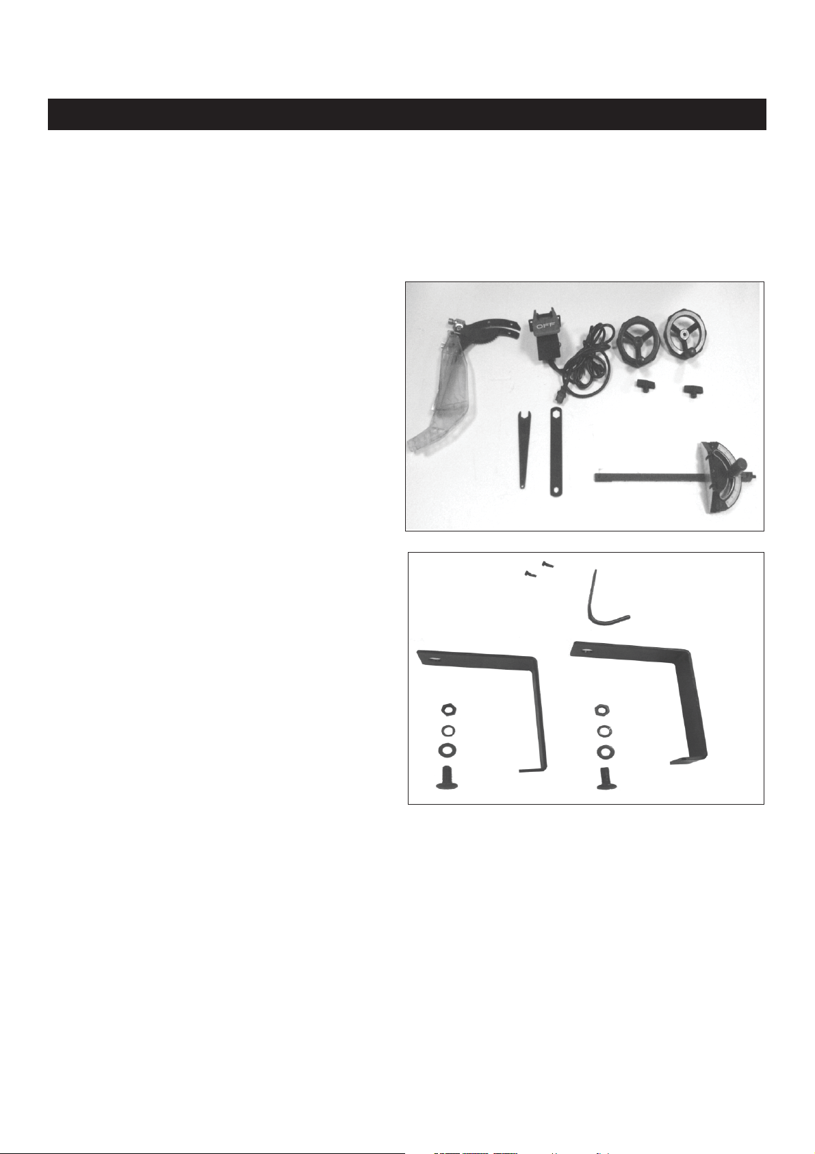
Contents of Package
Unpacking and Checking Contents
Unpack your 10-201 Contractor Saw from its carton and check to see that you have all of the
following items. Do not turn your saw ON if any of these items are missing. You may cause injury to
yourself or damage to your machine. If any parts are missing contact RIKON Technical Support at
1-877-884-5167 or techsupport@rikontools.com.
A) Blade Guard and Splitter Assembly
B) On/Off Switch
C) Miter Gauge
D) Blade Wrench
E) Blade Wrench
F) Handwheel Assembly(2)
G) Handwheel Lock Knob(2)
AA) M4x8mm ROUND HD TAP SCREW (2)
AB) WRENCH HOOK
AC) M8 HEX NUT (2)
AD) M8 SPRING WASHER (2)
AE) M8 FLAT WASHER (2)
AF) M8X16mm CARRIAGE SCREW (2)
AG) FENCE BRACKET (2)
5
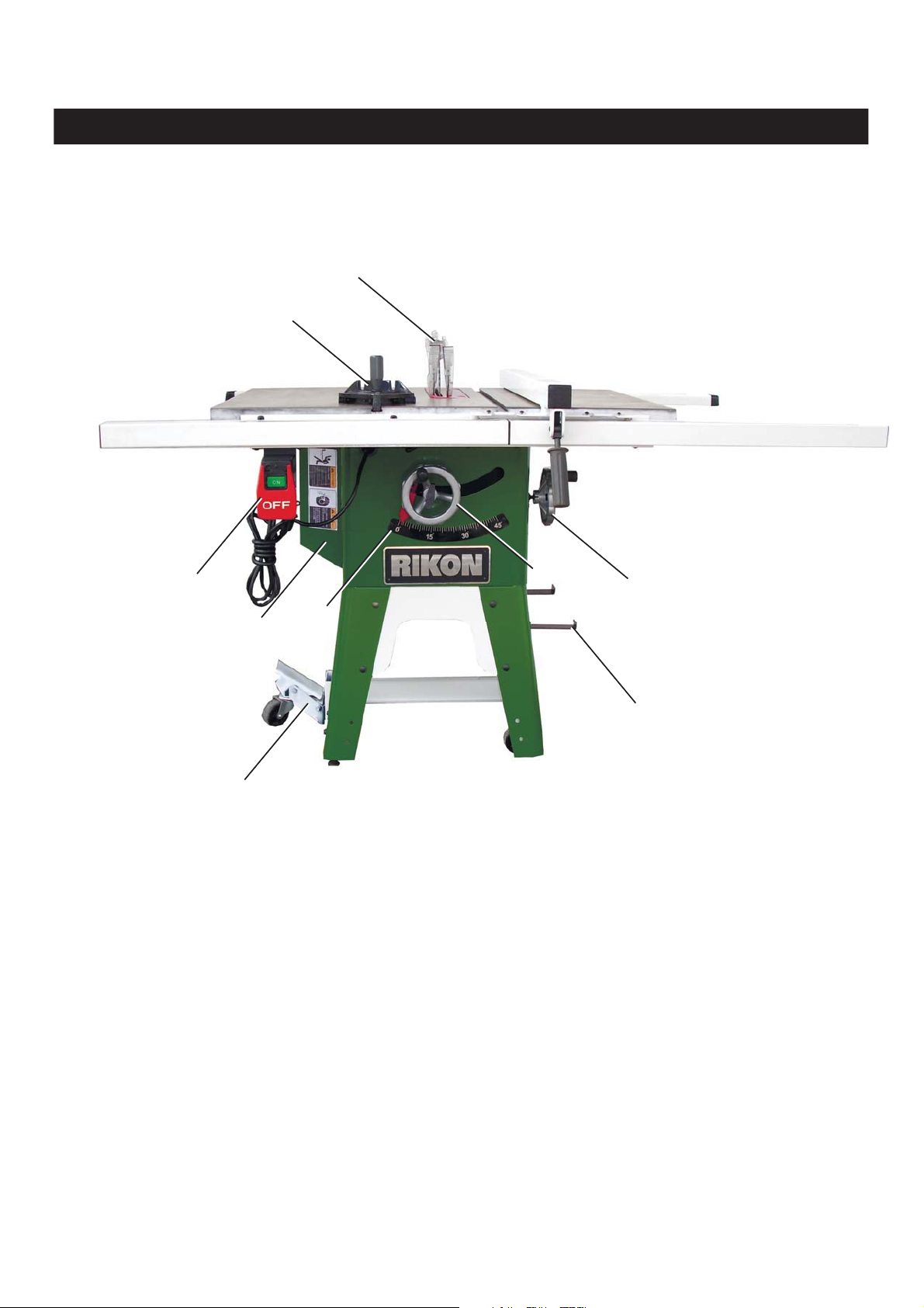
Getting to Know Your Table Saw
B
A
H
C
I
D
E
F
G
A) Miter Gauge
B) Blade Guard Assembly with riving knife
C) Motor Cover
D) Bevel Scale
E) Height Adjustment Handwheel
F) Bevel Adjust ment Handwheel
G) Fence Hooks(2)
H) On/Off Switch
I) Mobile Base Caster Assembly
6

• The table saw is a heavy machine; two people may be
required for certain assembly operations.
• DO NOT assemble the table saw until you are sure the
tool is unplugged.
• DO NOT assemble the table saw until you are sure the
power switch is in the "OFF" position.
• For your own safety, DO NOT connect the machine to
the power source until the machine is completely
assembled and you read and understand this entire
User Manual.
INSTALLATION AND LEVELING
Final location for the saw must be level, dry, well lighted,
and have enough room to allow movement around the
saw with long pieces of wood stock.
Level the saw front to back and side to side. If necessary,
but make sure the saw is stable before being placed in to
service.
CABINET LEG ASSEMBLY
1. Attach leg assemblies (A) to the right (J) and left (k)
of the table saw cabinet by placing (B) eight
M8X16mm carriage screws through the mounting
holes and place an M8 flat washer, M8 lock washer
and M8 hex nut onto each of the eight screws
attaching leg assembly to cabinet. Do not completely
tighten hardware at this time.
2. Attach two tie bars(C) and (H) between right and left
legs inside and tighten them with D) eight
carriage screws M8 flat washer M8 lock washer
and s.
M8 hex nut
3. Attach middle bar (E) between tie bar (H) and (C)
inside, using four
washers M8 lock washers and M8 hex nuts to tighten
SEE FIG.1
it.
4. To tighten the legs (A) and tie bar (C) by two (L)
M8x45mm hex soc head screws, M8 flat washers, M8
lock washers;
5. Attach Mobile base caster assembly (I) to the tie bar
(H) and using two M8X16mm carriage screws and M8
flange hex nuts to tighten it.
6. Place two leveling screws (G) to the lags (A) and
place an M8 flat washer, M8 lock washer and M8 hex
nut onto each of the two screws and tighten them.
7. Attach two caster wheels(F) to the tie bar(C) and
place two M8x55mm hex soc head screws through the
mounting holes of the bar and wheels, and using M8
lock nut to ighten them.
M8X16mm carriage screws M8 flat
t SEE FIG.1
( M8X16mm
ss
1. Turn the table saw side lay. The table saw
is heavy; two people are required for this operation. Be
sure to lay cardboard on the floor to protect the table
and cabinet.
CAUTION:
Fig. 1
I
G
H
K
E
D
A
B
J
L
C
F
L
Fig.2
7. To align the hole of cabinet with the hole of cabinet
leg, and using eight M8x20mm hex head screws, M8
flat washers M8 lock washers and M8 hex nuts to
tighten them.
SEE FIG.2 & FIG.3
7
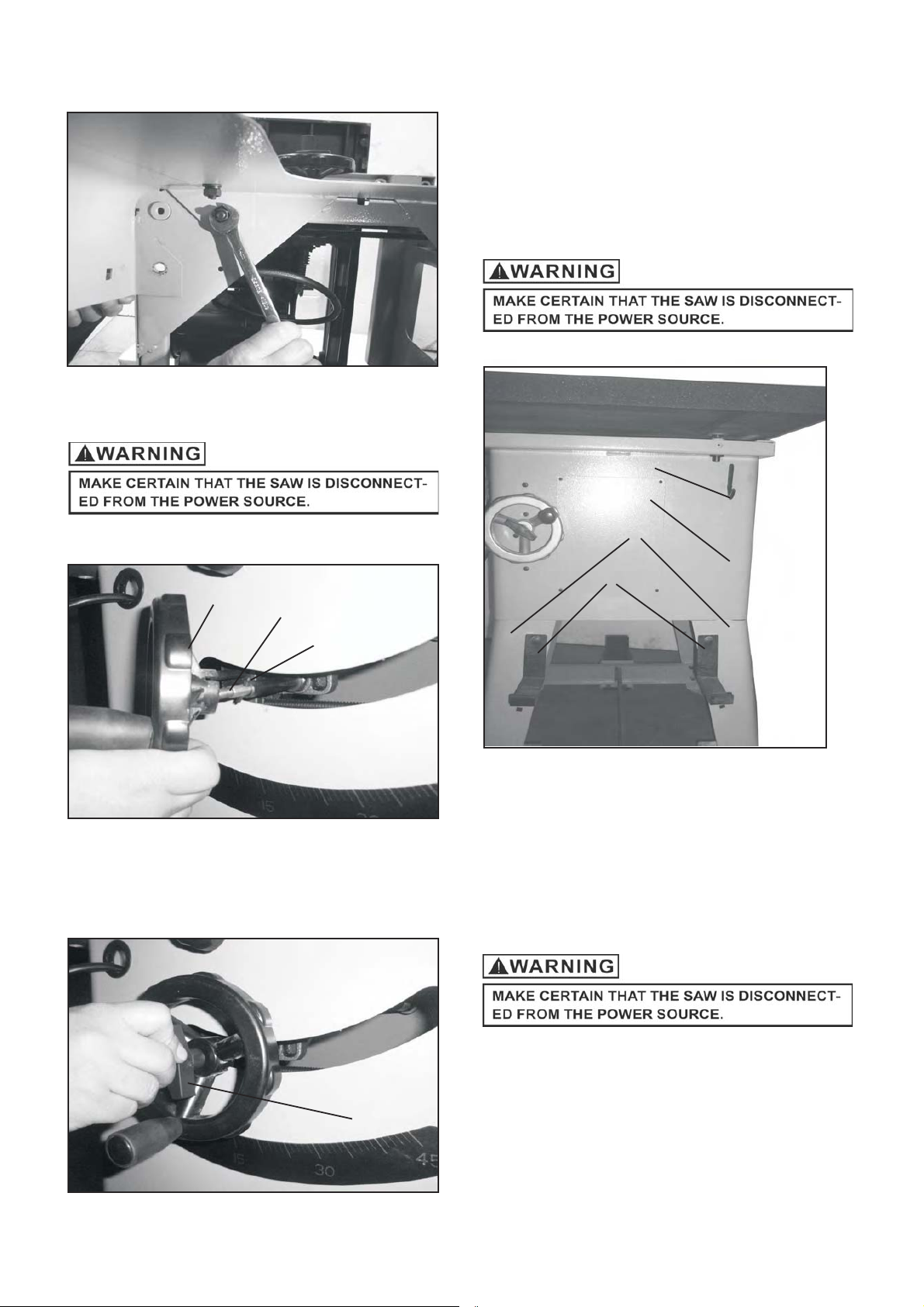
Fig.3
HANDWHEEL ASSEMBLY
2. Thread the locking knob (D) onto the threaded end of
the shaft.
3. Repeat the steps above to assemble the remaining
handwheel and locking knob onto the bevel shaft
located on the side of the cabinet.
SEE FIG 5.
WRENCH AND FENCE HOOK
ASSEMBLY
Fig.6
A
D
Fig.4
A
B
C
1. Place one of the handwheels (A) onto the blade
raise/lower shaft (B) located on the front of the
cabinet. Align the groove in the back of the
handwheel with the pin (C). SEE FIG 4.
Fig.5
B
C
1. Assemble both of the fence hooks (C) to the left
right cabinet leg (B) using four M8x16mm
carriage screws, M8 flat washer, M8 lock washer and
M8 hex nut to tighten them.
2. Assemble wrench hook (A) to the right side of cabinet
(D) using two M4X8mm round head tap screws.
SEE FIG 6
and
POLY-V BELT REPLACEMENT
1. 6 5 10 cross ALoosen of M x mm pan head tap screws ( )
and remove the cabinet access door. SEE FIG. 7.
D
8
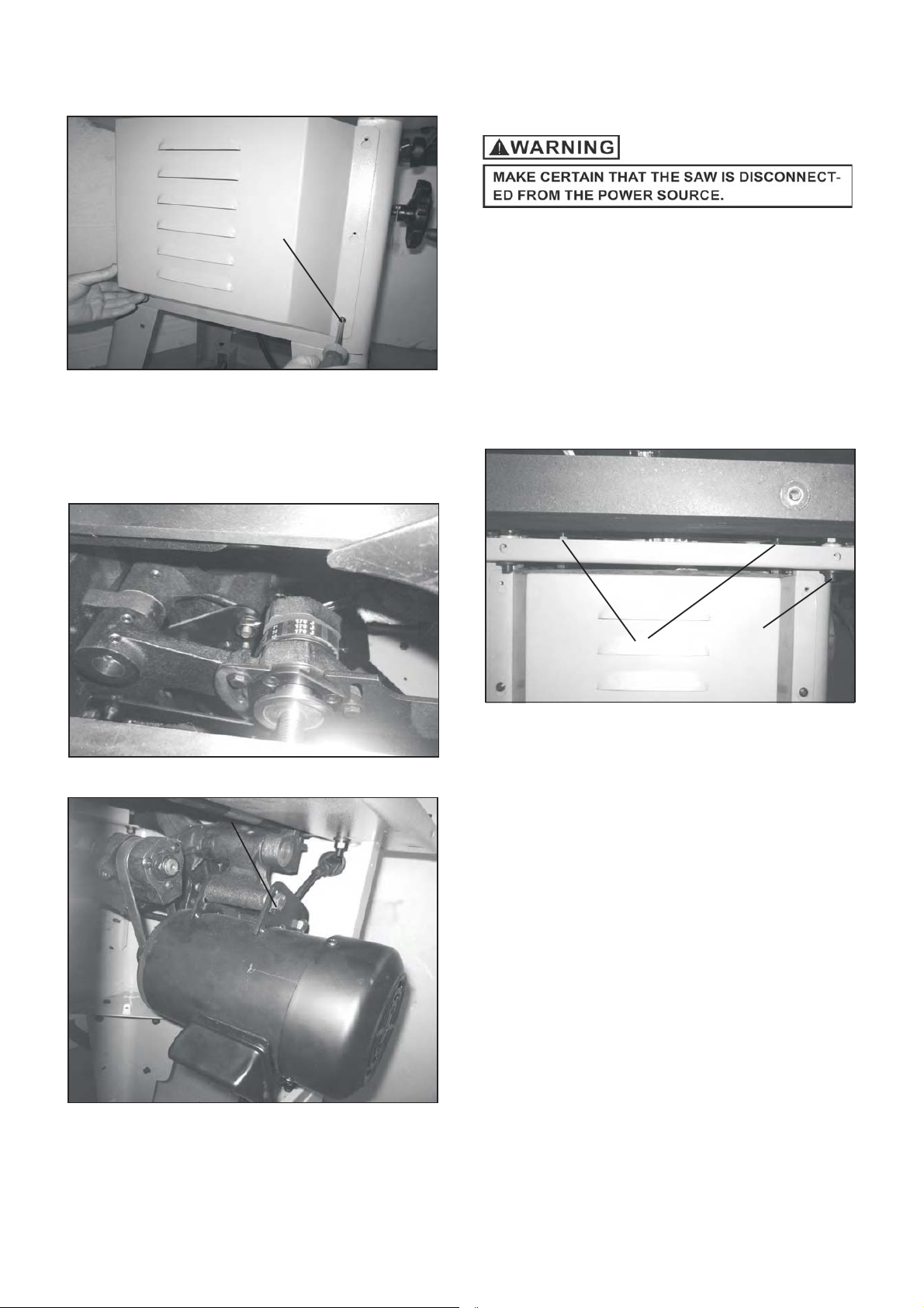
Fig.7
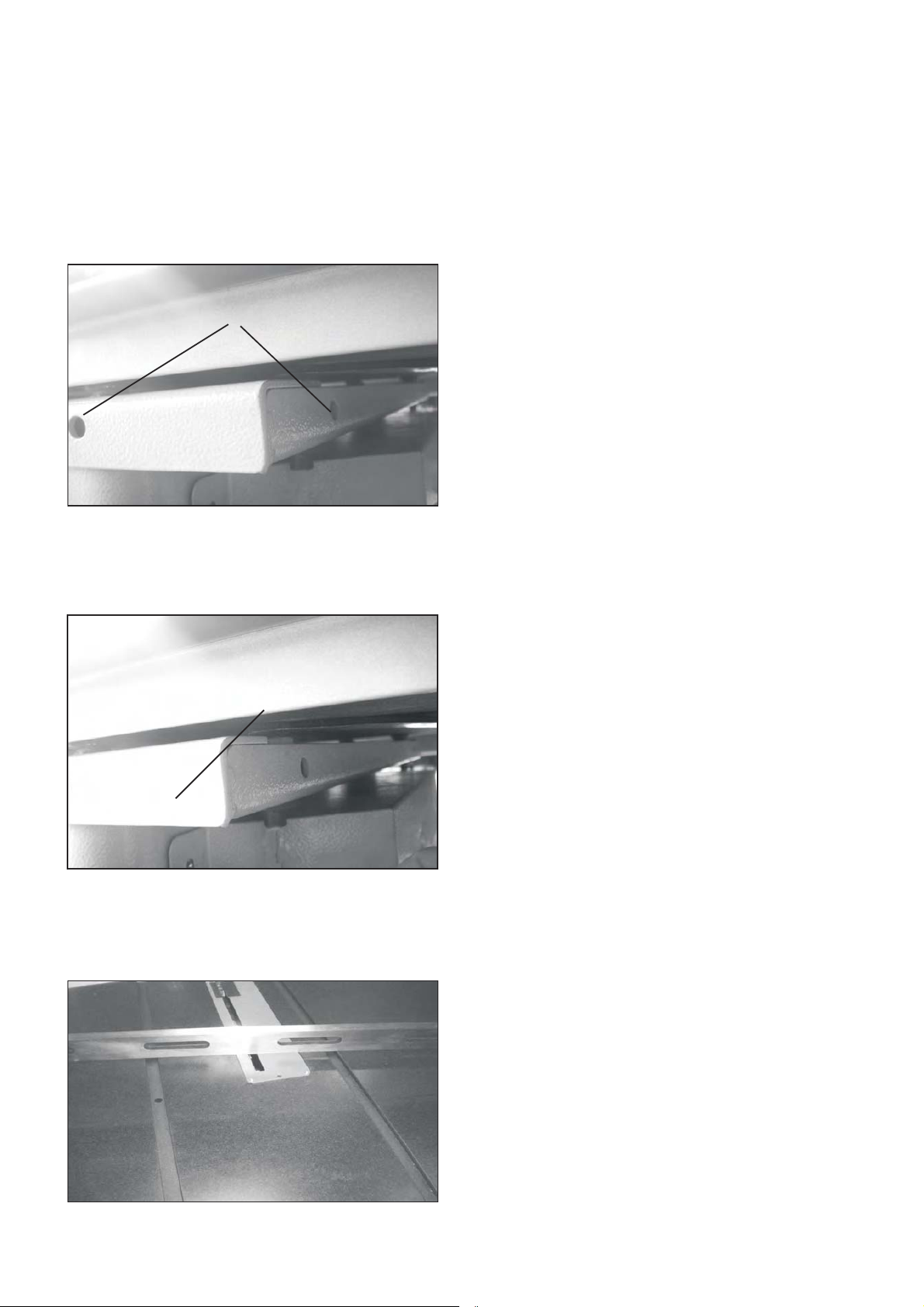
1.One person put right/left extension wing on the top of
cabinet. Alignment pin into bottom of wing (A).
SEE FIG.10
2.
Another
person
locks 4
bolts(B(B)
with
flatanand
spring
washeranand
fromththe
bottom of
cabinetanand
tighten
it.
SEE
FIG.1010
Neednonot
adjustththe
flatness
for
extension
wings
after
assembling.
Because we
have
doneththe
pre-
adjustmentanand
pre-setting of
the
extension
wingsfoforththe
flatnessinin
factory.
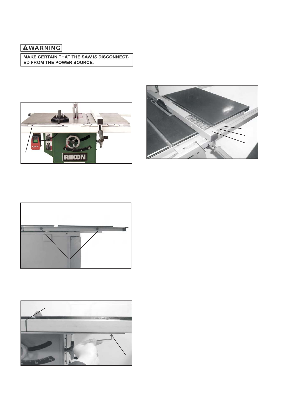
EXTENSION WING ASSEMBLY
A
2. Install the belt on the Arbor Pulley and raise motor
by loosing 1 of the motor mounting screws (B) to
reach the belt distance for assembling the belt on
the motor Pulley. SEE FIG.8 & FIG.9
Fig.8
CAUTION: The extension wing is heavy; two people are
required for assemble. The installation method for
granite and cast iron wing is the same.
1.One person put right/left extension wing on the top of
cabinet. Alignment pin into bottom of wing (A).
SEE FIG.10
Fig.10
A
B
Fig.9
B
3. Replace the cabinet access door.
Anothe
2. Another person locks 4 bolts (B) with flat and spring
washe
washer and from the bottom of cabinet and tighten it.
SE
SEE FIG. 10
NOTE: Step1 and step2 can complete
perso
FIG
lock
fro
bolt
botto
wit
fla
cabine
spring
tighte
it.
the assembly for extension wings easily.
Need not adjust the flatness for
Nee
extension wings after assembling.
extensio
Because we have done the pre-
Becaus
adjustment and pre-setting of the
adjustmen
extension wings for the flatness in
extensio
factory.
factor
adjus
wing
hav
wing
flatnes
afte
don
pre-settin
for
assembling.
pre-
the
flatnes
9
3. The user can adjust the flatness for the extension
3. The user can adjust the flatness for the extension
Wings to obtain more flatness. We suggest that user
need not do this adjustment again, the process are as
following if user want to do the adjustment again.
Wings to obtain more flatness. We suggest that user
need not do this adjustment again, the process are as
following if user want to do the adjustment again.
4.To loose 4 screws (B) by 6.0mm Allen Wrench;
5.To loose 4 setting screws (C) by 2.5mm Allen wrench.
SEE FIG.12
Fig.12
C
6.EUsing an open wrench to adjust the 4 elevation
screws ( ) to raise or lower the extension wing to the
table. SEE FIG.13
8. Make sure both wings are aligned, if not, refer to step
(6) until completely adjusted.
9.
Using a 6.0mm Allen wrench to secure 4 screws (B).
Fig.13
E
7.Use a straight edge across to the main table and
extension wings, checking the flatness of both main and
extension wings. SEE FIG.14
Fig.14
10
FENCE ASSEMBLY
1. Fasten the front rail to the table top using four
5/16-18x5/8mm cup hex soc head screws (A)
SEE FIG.17
Fig.17
4. Connecting the right guide tube(long)and left guide
tube(short)with cap (D), and place them on the front
rail.
5. The guide tube must be fasten by eight M6X16mm
hex soc round head screws(C) with M6 flat washer
and M6 lock washer. SEE FIG.19
Fig.20
G
F
E
A
2. Fasten the left rear rail to the table using two
5/16-18x5/8mm hex head screws(B) with M8 flat
Washer and M8 lock washer. SEE FIG.18
Fig.18
B
3. The installation method for right rear rail is the same
As the left one.
G
7. Place the Fence Body (E) on the table top and
against the blade to make sure that if the "zero"
scale on the cursor (F) is align with the "zero" scale of
the right/left scale label stuck on the guide tube.
8. Loosen the pan head screw (G) and move the cursor
(F) till the zero scale aligns with the zero scale on the
right/left scale. SEE FIG.20
Fig.19
D
C
11
RIVING KNIFE/SPLITTER COMPONENTS
ASSEMBLY
Note: Remove the table insert ( Table insert are gripped
by four magnets on the table).
Fig.21
Fig.22
B
C
Fig.23
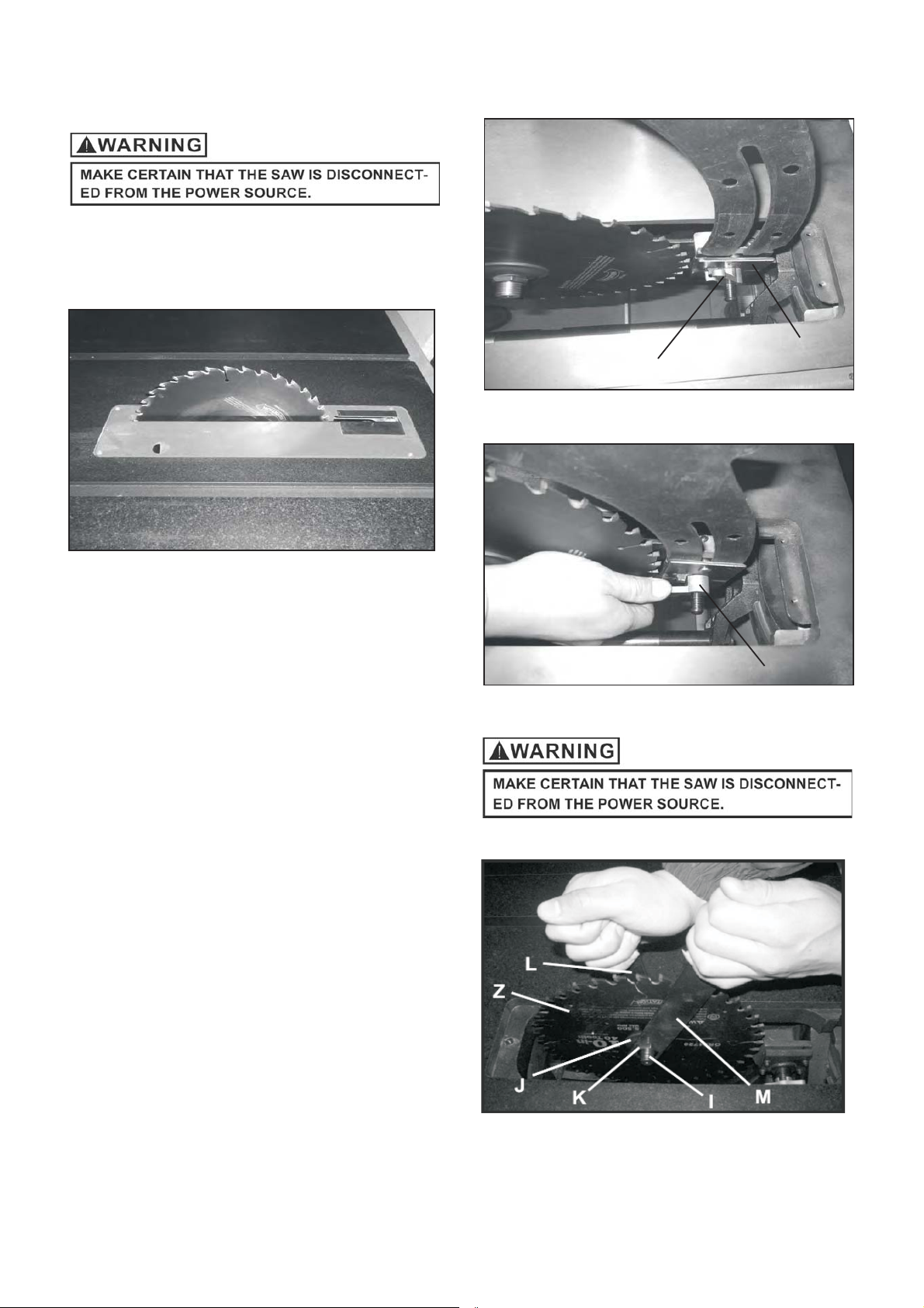
INSTALLING AND REMOVING
THE RIVING KNIFE/SPLITTER
1. Loosen the knob (C),Line up the riving knife/splitter in
the proper direction to the mounting bracket (B).
SEE FIG22.
2. Push the Riving Knife/ all the way down into the
mounting bracket, make sure the location pin is
properly locked in the hole of the Riving Knife/ .
(The location hole is on the button side of the Riving
Knife/ ).
splitter
3. Tighten the fasting knob(C).
splitter
splitter
SEE FIG.23
•Remove
1. Loosen the fasten knob (C).
2. Remove the Riving Knife/ out of mounting
bracket.
NOTE:
Make sure blade or arbor is at the highest
position before adding or removing the riving
splitter
Knife/ .
splitter
C
BLADE ASSEMBLY
Fig. 24
12
 Loading...