

Page 1
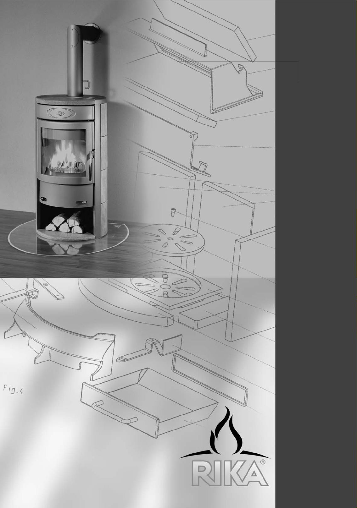
The soul of your home
RIKA STOVES
MANUAL
VIVA
Page 2
2
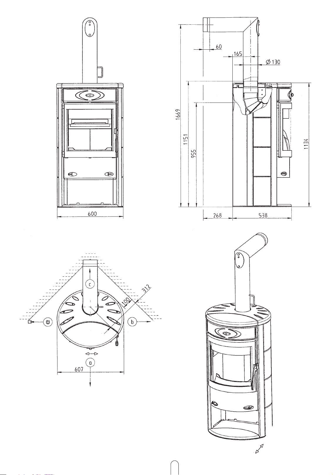
Fig. 1
Fig. 2
OPEN
CLOSED
OPEN
CLOSED
Page 3
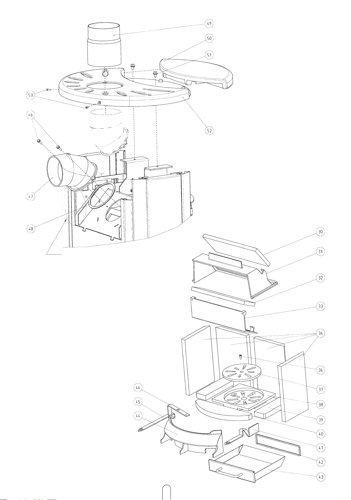
Fig. 3
3
Fig. 4
Cut through pre-shaped section at
four points
Page 4
4
Fig. 5.1
Fig. 5
Secondary air slide
Shaker grate lever
primary air supply slide
Fig. 6
Version
Ceramic
Plate
Soapstone
Page 5
5
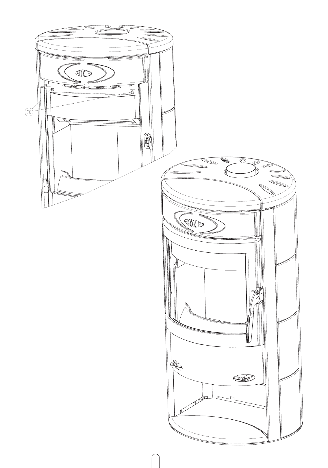
Fig. 7
Fig. 10
Page 6

4. FITTING OPTIONS
EXPLANATION OF SYMBOLS
2. INSTALLING THE STOVE
1. IMPORTANT INFORMATION
CONTENTS
Important information
Practical advice
Use the plan
6
3. OPERATION
5. MAINTENANCE AND CLEANING
6. GUARANTEE AND WARRANTY
ENGLISH
Technical Specification and spare parts overview 7
General warning and safety instructions 8
Before setting up 8 - 9
BRIEF HEATING INFORMATION
Suitable fuels and fuel quantities 10
Fuel quantities 10
Maximum fuel quantity 10
Clean combustion 11
Burning wood 11
Changing the flue direction 12
Changing the flue plate 12
Making the stove connection 12
Lighting the fire 13
Ash drawer 14
Operating the shaker grate 14
Slide setting at rated heating capacity 14
Changing flue pipe connection above to connection below 15
Fitting the tile panel 15
Fitting the sheet metal panelling 15
Fitting the stone plates 15
General maintenance 16
Finish – condition and cleaning 16
Convection air openings 16
Cleaning the flue gas channels 16
Wechseln der Zugplatte 16
PROBLEM SOLVING
What to do if ? 17
We guarantee 31
Guarantee card 31 - 32
Page 7
TECHNICAL SPECIFICATION
(Fig. 1)
This is a Type 1 stove and has a connection
for fitting to a chimney that is equipped for
other stoves and boilers for solid and liquid
fuels, insofar as the chimney dimensions are
in accordance with DIN 4705, Part 3.
The owner of the small heating system or
the authorised person for the small heating
system must keep the technical documentation
in a safe place and present it to the local
authority or the chimney sweep if required.
PAC K AG I NG
Your first impression is important to us!
- The packaging for your new stove provides
excellent protection against damage.
However damage to the stove and accessories
can occur during transport.
Therefore please check that your stove is
undamaged and that all parts are there on
receipt! Report any defects to your stove
dealer immediately!
The wood in the packaging has not been surface treated and can therefore be burned in
your stove. The box and the film (PE) can be
safely taken to the local council waste disposal depot for recycling.
- The packaging for your new stove generally has
no effect on the environment.
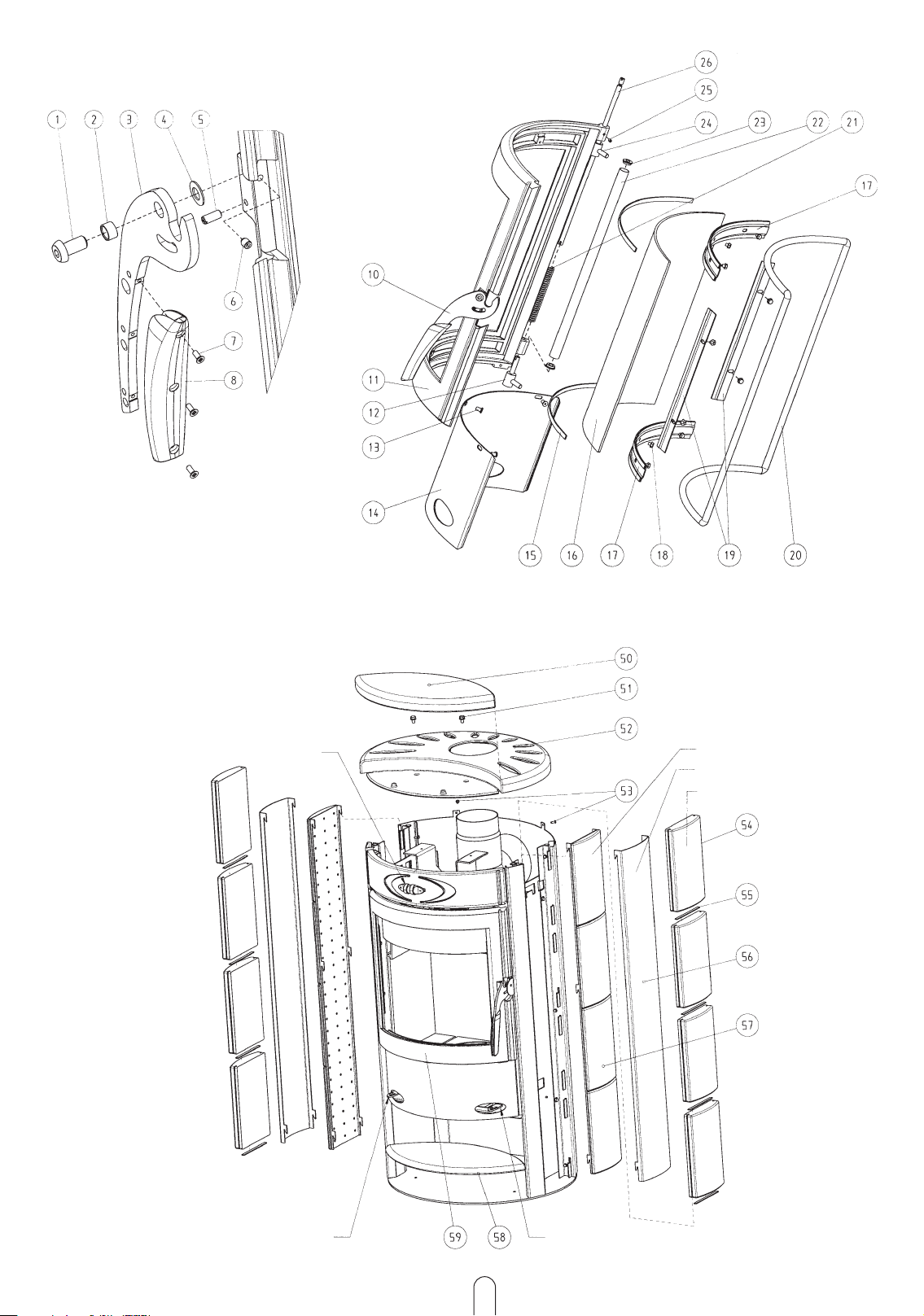
PARTS - OVERVI EW
(Fig. 3 - 7)
DESCRIPTION
01 Lens head screw with Allen screw M8 x 16
02 Handle sleeve
03 Door lock
04 Spring washer
05 Grub screw M5
06 Grub screw M4
07 Countersunk screw with slot M3 x 6
08 Handle
10 Door handle
11 Grate door, machined and painted
12 Bottom stove strip, grey painted
13 Allen screw black galvanised M5 x 8
14 Skirting panel painted
15 Sealing ring flat CULIMETA 8 x 2
16 Grate door glass
17 Upper glass holder
18 Hexagonal screw V2A pressed washer
19 Side glass holder
20 Round sealing ring, black ?12
21 Pre-load spring
22 Sleeve grey painted
23 Spacer black galvanised
24 Stove strip upper, grey painted
25 Grub screw M5
26 Cotter pin black galvanised
30 Vermiculite plate
31 Flue plate
32 Vermiculite plate 2
33 Flue redirector machined
34 Side firebrick
36 Allen screw V2A M8 x 16
37 Cleaning slide
38 Floor grate
39 Floor firebrick side
40 Floor firebrick side
41 Slide grey
42 Round sealing ring, black ?8
43 Ash draw grey
44 Wood catcher painted grey
45 Shaker grate actuator, matt chrome
46 Shaker grate lever
50 Cover insert (ceramic or soapstone)
51 Duo Taptite M6 x 12
52 Cast lid machined and painted
53 Duo Taptite countersunk M5 x 12
54 Sidewall soapstone (x 4/side)
55 Sealing ring flat CULIMETA 8 x 2
56 Sidewall panel painted
57 Sidewall ceramic
58 Floor inlay (ceramic or soapstone)
59 Grate door
70 Lens head screw with Allen screw M8 x 16
All technical and layout changes as well as grammatical and printing faults excepted.
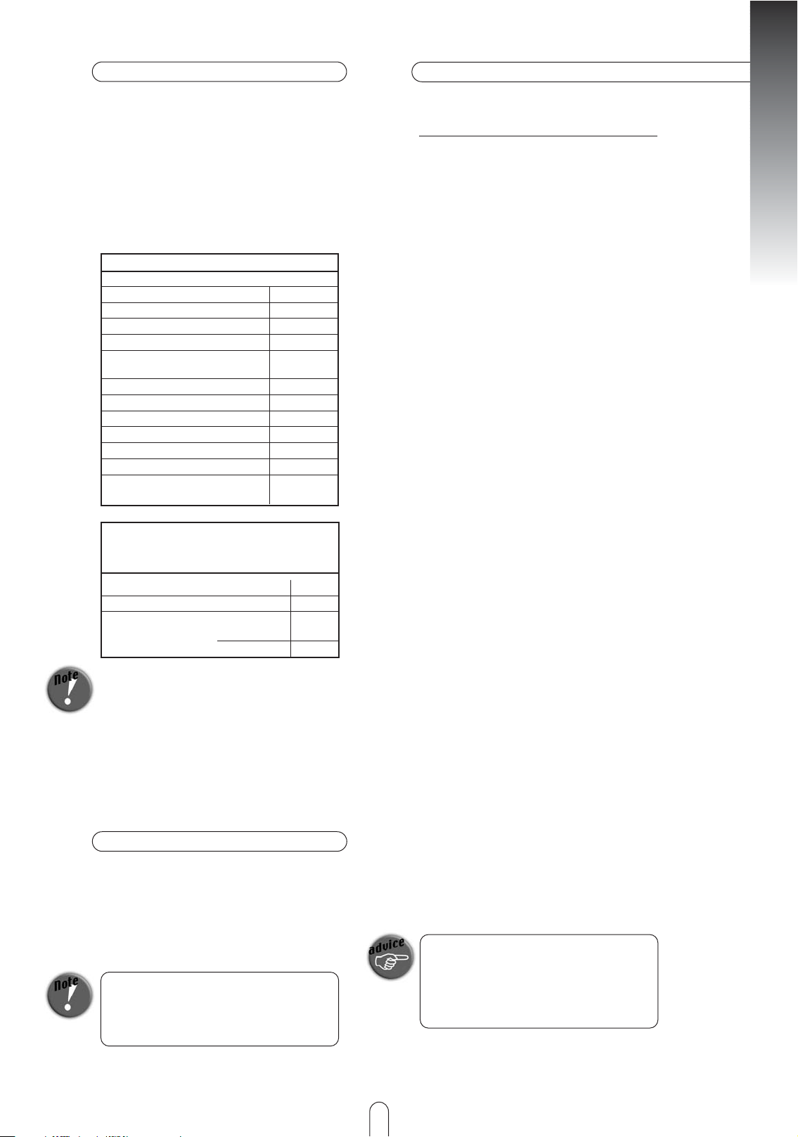
TECHNICAL SPECIFICATION
Dimensions (mm) and weights (kg)
Height
Width
Depth
Weight without casing
Weight with steel casing (floor and
cover insert ceramic
Weight with ceramic casing
Weight with natural stone casing
Flue pipe outlet diameter
Rated heating capacity as per DIN 18891
Maximum thermal output
Lowest thermal output
Room heating capacity (m
3
)
dependent on house insulation
1134
607
538
160
173
183
209
130
8 kW
11 kW
4 kW
90 - 180
Flue gas mass flow g/s geschlossen
Flue gas temperature/°C geschlossen
Minimum flow pressure at rated heating
capacity/mbar closed
at 0.8 times rated heat capacity
5,7
340°
0,1 2
0,08
Flue gas values for multiple connection to a
chimney as per DIN 4705, Part 3 or for measuring the chimney as per DIN 4705, Part 2
ENGLISH
7
Page 8
1. IMPORTANT INFORMATION
GENERAL WARNING AND SAFETY
INSTRUCTIONS
The general introductory warning
information must be followed.
➧ Read the whole of the manual thoroughly
before commissioning the stove.
➧ Only approved transport aids with
adequate load bearing capacity must be
used for transporting your stove.
➧ Your stove is not suitable for use as a
ladder or scaffold.
➧ Thermal energy is produced by burning
fuel; this leads to the surface of the stove,
the doors, the door and operating handles,
the door glasses, the flue pipes and possibly
the front wall of the stove becoming very
hot. Avoid touching these parts without
wearing the relevant protective clothing or
using the relevant means (cold hand).
➧ Make children aware of the danger and
keep them away from the stove when in
use.
➧ Only burn the approved fuel listed in the
chapter “Clean Burning”.
➧ Burning or inserting easily combustible
or explosive materials, such as empty spray
cans and suchlike in the stove, as well as
storage of the same close to the stove is
prohibited due to risk of explosion.
➧ When reheating, no wide or easily
combustible clothing should be worn.
➧ Placing non heat resistant objects on the
stove or nearby is prohibited.
➧ Do not lay washing on the stove to dry.
➧ Stands for drying items of clothing or
suchlike must be set up at an adequate
distance from the stove – fire hazard!
➧ Working with easily combustible and
explosive materials in the same or adjoining
room to the stove is prohibited when the
stove is on.
SAFETY CLEARANCES (Minimum clearances) Fig 2
1. From non-combustible items
a > 400 mm b > 100 mm c > 100mm
2. From combustible items and supporting walls made
from reinforced concrete construction
a > 800 mm b > 200 mm c > 200 mm
BEFORE SETTING UP
1.1 Ground load bearing capacity:
Before setting up, ensure that the supporting
construction has a load bearing capacity
that will support the weight of the stove.
1.2 Flue pipe connection
Flue pipes are a particular hazard source in
respect of escape of poisonous gas and fire
hazard. Obtain the advice of an appointed
specialist company in respect of laying and
fitting the pipes.
When connecting the flue pipe to the
chimney, in the area of walls with wood
cladding, please follow the relevant fitting
directives.
ENGLISH
8
Page 9

1.3
You must keep an eye on flue gas formation
in the event of unfavourable weather
(atmospheric inversion) and the draught
conditions. If too little combustion air is
added smoke can enter your house or flue
gases can escape. Additionally harmful
deposits can arise in the stove and in the
chimney.
If flue gas escapes let the fire go out and
check if all air inlet openings are free and
the flue gas feeds and the stovepipe are
clean. In cases of doubt you must inform
the master chimney sweep, as a fault in the
draught could be due to the chimney.
1.4
Before adding new fuel, push the embers
together to form a bed of embers.
1.5
Only use a suitable tool from our accessory
range for pushing the embers together, and
ensure that no combustible material falls
out of the stove.
1.6
Place brown coal briquettes on the embers
in a single layer, with finger width spacing.
1.7
Use the devices supplied with your stove,
such as the protective gloves or the cold
hand to open the doors, as well as for
operating the control elements.
1.8
S
toves of Type 1 (BA 1)
These stoves must only be operated with
the grate door closed.
1.9
The grate door must only be opened for
adding fuel and must then be closed again,
as this could otherwise lead to danger for
other stoves that are also connected to the
chimney.
1.9.1
When the stove is not in operation, the
grate door must be kept closed.
1.10
When using wet fuel and if operation is
restricted too much, the chimney can soot
up, i.e. easily combustible materials such as
soot and tar can be deposited and this can
lead to a chimney fire.
Should this happen, close all air inlet slides
and flaps. Call the fire brigade and get
yourself and all other occupants to safety.
CAUTION: The size of the grate door means
that, particularly when reheating blazing
flames, the door must not be opened abruptly,
in order to prevent the flames from jumping
out.
9
ENGLISH
Page 10
SUITABLE FUELS AND FUEL
QUANTITIES
In principle your stove is suitable for bur-
ning dry billets. You can also burn fuels such
as wood briquettes.
Only use dry fuel. The burning of waste of
any kind, in particular plastics, will damage
your stove and the chimney, and is prohibi-
ted by the Emissions Protection Act.
FUEL QUANTITIES
The stove is equipped with flat firing due to
the design. This means that only one layer
of fuel may be placed on the existing basic
embers. Please note that when a larger
quantity of fuel is added, your stove will
emit a larger quantity of heat or will heat
up more fiercely than is intended for the
design. This can lead to damage to your
stove.
MAXIMUM FUEL QUANTITIES
Wood:
2 billets approx. 0.9 kg
Wood briquettes (broken):
2 off approx. 0.9 kg
Your stove output is regulated via the air
inlet slide. As your stove output is also
dependent on the chimney draught, you
must use this slide based on your own
experience.
The secondary air regulator, the primary air
regulator and the shaker grate handle may
only be used with the shaker hook provided.
ENGLISH
10
BRIEF HEATING INFORMATION
Page 11
The challenges of the present day and age
mean that everyone must act responsibly.
One of most important matters of concern
is retaining our natural world. Our products
are developments that comply with the
most recent state of the art technology.
This is an essential prerequisite for a clean,
efficient and perfect functioning of our
stoves.
CLEAN BURNING
The following is important for clean burning:
1. THE FIREWOOD MUST BE DRY AND
UNTREATED.
Recommended value < 15% rel. Wood
humidity.
Dry and well ventilated stored wood that
has been stored for 2-3 years.
A stove is not a “waste incineration plant”. The
warranty will become null and void if rubbish or
non-approved material, such as plastic, treated
wood etc. is burned.
Further consequences are damage or soiling of
the stove and chimney as well as the
environment!
2. CORRECT FIREWOOD QUANTITY
AND FIREWOOD SIZE
➧ Too much firewood causes overheating.
This causes the material to burn too heavily
and your stove will produce poor flue gas
values
➧ Too little firewood or billets that are too
means that the stove does not reach the
optimum temperature. The flue gas values
are poor in this respect too.
➧ The correct firewood quantity means:
for wood ? 1.6 kg (2 billets - 25 cm long)
per layer (recommended value) at rated
thermal output 8 kW.
At the smallest thermal output (4 kW) ?
0.8 kg (2 billets - 25 cm long)
Note: Only wood and wood briquettes must be
burned in your stove. Plastic, treated wood
materials (e.g. chipboard), hard coal or textiles
must not be burned.
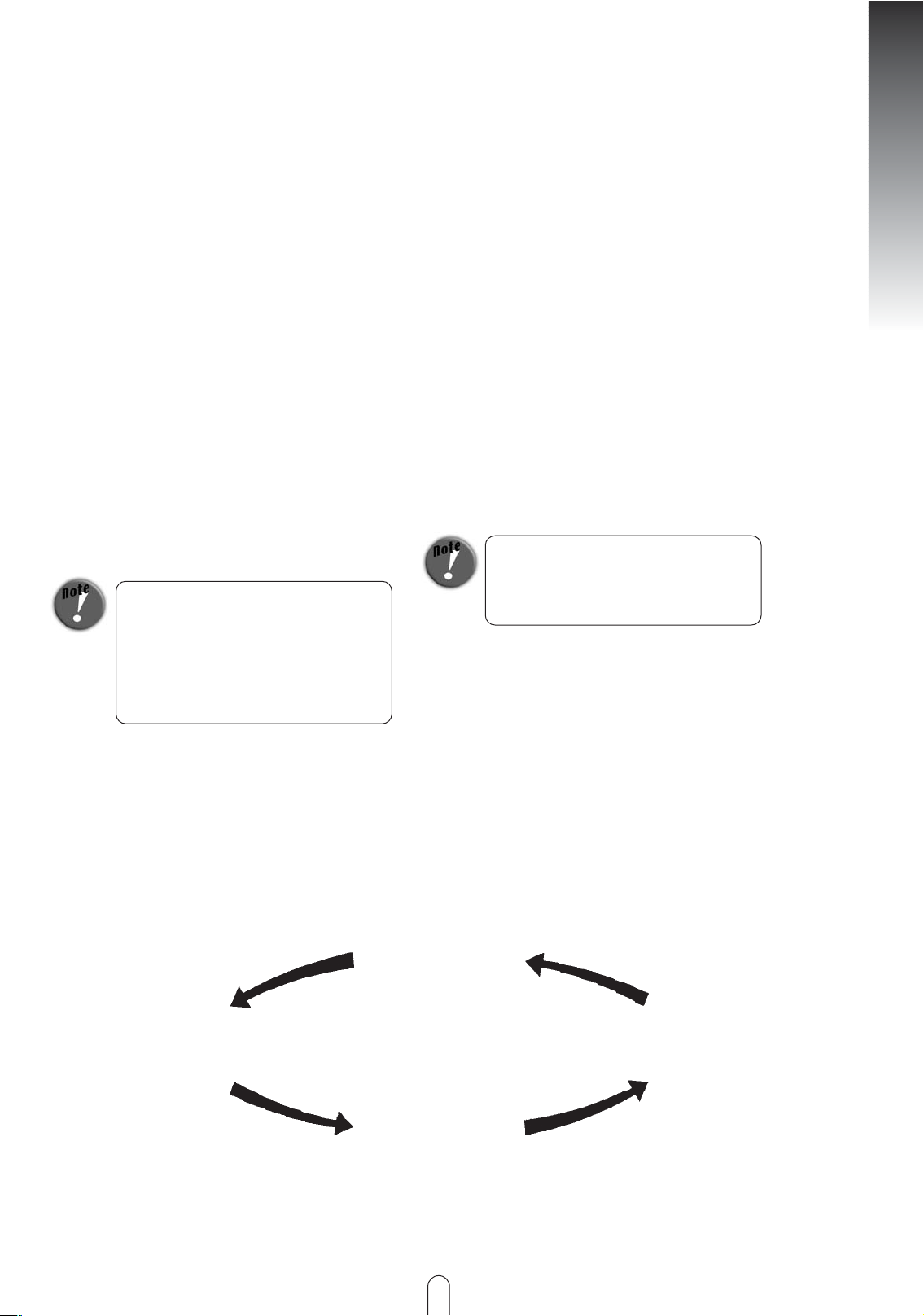
BURNING WOOD
Clean burning of wood corresponds to the
same chemical process as natural decay, i.e.
the CO2 (carbon dioxide) released does
not increase or contaminate the original
CO2 content of the atmosphere.
Plant
growth
Wood decomposition
Wood burning
Wood
CO2 content of
atmosphere
11
ENGLISH
Page 12
CONNECTING THE CHIMNEY
Proceed as follows when fitting a connec-
tion to a bricked chimney:
ENGLISH
12
2. INSTALLING THE STOVE
Care must be taken with this stove that the
flue draught reaches at least the prescribed
value (> 0.8 mbar). Should problems arise
here, please contact your master chimney
sweep.
Before first commissioning or after changing
the location of the stove, cleaning and service
work, ensure that the flue plate (Fig. 4, Part
31), as well as the flue direction (Fig. 4, Part
33) as well as the wood catcher (Fig.4, Part 44
are correctly positioned. When using a flue
pipe with throttle valve, the throttle valve must
be open.
CHANGING THE FLUE DIRECTION
(Fig. 7, Fig. 4)
If the flue direction or the integrated
vermiculite plate in your stove is fractured
and needs to be exchanged or unscrewed,
loosen the two attachment screws (Fig. 7,
Part 70) and lift the part out of the grate.
The vermiculite plate is inset and can now
be easily changed.
CHANGING THE FLUE PLATE
If the flue plate in your stove needs to be
changed (Fig. 4, Part 31) loosen the two
attachment screws as described above and
lift the flue direction out.
Then move the flue plate slightly to the left
and remove the side firebrick. Now you can
turn the flue plate diagonally and rotate it
through the grate opening.
The vermiculite plate is only pushed in and
can be easily changed.
1. Measure and draw in the chimney
connection (taking any floor plate
thickness into account) as per the natural
dimension
2. Chisel out (drill) the holes in the wall
3. Brick in wall lining
First seal the wall lining using mineral wool
insulation. Afterwards plaster using heat resistant cement mortar or equivalent.
4. After the mortar has hardened, and after
plastering and painting, position the
floor plate including the floor protection
(carton).
5. The stove can now be lifted onto the
floor plate carefully.
The stove must not be pushed along an
unprotected floor.
Strong corrugated cardboard, carton, or an old
carpet are excellently suited as an installation aid
and an underlay. The stove can also be pushed on
this underlay.
We recommend original flue pipes from
the RIKA flue pipe range for professional
connection. The connecting piece must not
project into the chimney shaft! Seal the gap
between the flue pipe and wall lining using
a ceramic seal.
The installation must comply with the respective
safety and construction regulations. Please
contact your master chimney sweep in this
respect – he will be happy to give you
information.
If you use a system chimney (e.g. glazed fireclay), please follow the manufacturer’s connection instructions precisely.
Page 13
13
3. OPERATION
LIGHTING THE FIRE (Fig. 17)
In order to keep exhaust emissions as low
as possible, we would ask you to keep to
the following starting instructions.
1.
If the stove and chimney are still cold or if
there is atmospheric low pressure, then
burning some paper at the start is recom-
mended, in order to “drive” the cold out of
the stove and chimney.
2.
To start heating first lay 1 kg wood (2 billets)
on the floor of the grate, on top of that 0.5
kg soft wood chip and 1 kg wood (3 small
billets)
Pull the shaker grate handle (Fig. 4) out
completely and open the primary (Fig. 4)
and secondary air slide (Fig. 4)
3.
Now light the paper. Wait until the soft
wood chips are burning well.
Close the shaker grate handle and the pri-
mary air slide a few minutes later. Set the
secondary air slide to the ideal setting a few
minutes later.
Please do not use glossy paper or paper from
magazines. It does not burn well and the print
colours produce very poisonous substances in
the flue gas.
4.
After this has burned, lay approx 1.6 kg
wood (2 billets) on the fire. Open the sha-
ker grate handle and the primary air slide
until the wood is burning well (approx. 2
mins). The secondary air slide (part 3)
remains in the ideal setting.
Proceed in the same manner for each furt-
her layer.
5.
The mineral parts of the wood (approx. 1%)
remain on the bottom of the grate as com-
bustion residue.
Because it is a natural product this ash is an
excellent fertiliser for all plants in the gar-
den. However the ash should be left to
settle beforehand and doused with water.
ENGLISH
Page 14

THE STOVE PAINT ONLY HARDENS PROPERLY
AFTER HEATING UP DURING USE.
- Do not touch the surface during heating. It is
still soft.
- Our paints are completely harmless in
accordance with the TÜV certificate; there is no
danger to health. In spite of that we recommend
that the house is well ventilated several times
after first heating.
- Heat the stove up well – this will reduce the
hardening time.
- Hardening of the surface is complete after
several proper periods of heating.
- All details on the nature of the firewood and
correct heating can be found in Chapter 1.
ASH DRAWER
The ash drawer must be emptied regularly
to prevent excessive heating of the fire grid.
Never heat the stove with the ash drawer
open → danger of overheating → loss of
warranty.
Caution: Embers could remain in the ash. Empty
the ash into non-flammable containers and do
not place the ash drawer on flammable
surfaces.
OPERATING THE SHAKER GRATE
The ash is transferred from the fire to the
ash drawer by moving the shaker grate
handle back and forth. This frees up room
for the primary feed air that is required for
the heating phase in the stove.
It is not necessary to operate the shaker
grate during heating.
SLIDE SETTING AT RATED THERMAL
OUTPUT
Fuel
Wood/
Wood briquettes
Primary air
Secondary air
Shaker grate
closed
1/3 auf
closed
The position “Primary air completely open”
may only be used as a starting position.
As the performance of your
ENGLISH
14
Brown coal
briquettes
1/2 open
1/4 open
open
Page 15

15
FITTING THE SHEET METAL PANELLING
(Fig. 6)
1. Remove the cover insert (Fig.6, part 50)
from your stove.
2. Remove the cast cover (Fig.6, part 52) by
unscrewing the two hexagonal screws
above and the two countersunk screws
on the rear of the cast cover.
3. Take the panelling (right or left) and push
it with the mounting clips over the
mounting strip on the stove body
Now press the panelling against the stove
body and allow it to drop slowly
downwards. Do the same on the other
side.
FITTING THE STONE PLATES
(Fig. 6)
1. Remove the cover insert (Fig.6, part 50)
from your stove.
2. Remove the cast cover (Fig.6, part 52) by
unscrewing the two hexagonal screws
above and the two countersunk screws
on the rear of the cast cover.
3. Glue sealing strips to the stone plates
(Fig. 6, Part 55)
4. Push the stone plate down through the
two grooves on the clips of the retaining
strip mounted on the stove body (four
per side). Do the same on the other side.
4. FITTING OPTIONS
ENGLISH
CHANGING FLUE PIPE CONNECTION
ABOVE TO CONNECTION BELOW
(Fig. 3)
1. Remove the cover insert (Fig.3, part 50)
from your stove.
2. Remove the cast cover (Fig.3, part 52) by
unscrewing the two hexagonal screws
above and the two countersunk screws
on the back panel.
3. Now the two hexagonal screws that
secure the flue gas connection can be
accessed.
4. Loosen the two hexagonal screws and
rotate the connector by 180°.
5. Before refitting in reverse order remove
the pre-cut circular section in the rear
panel (Fig.3)
FITTING THE TILE PANEL
(Fig. 6)
1. Remove the cover insert (Fig.6, part 50)
from your stove.
2. Remove the cast cover (Fig.6, part 52) by
unscrewing the two hexagonal screws
above and the two countersunk screws
on the rear of the cast cover.
3. Take the panelling (right or left) and push
it with the mounting clips over the
mounting strip on the stove body
Page 16
5. MAINTENANCE AND CLEANING
ENGLISH
16
GENERAL MAINTENANCE
Your Viva has been designed by our deve-
lopment team with minimal maintenance in
mind and for a very long service life.
Certain cleaning activities and checking the
seals are however necessary from time to
time. The time periods between the
inspection intervals are above all depen-
dent on the fire wood quantity used and
the frequency of use.
Maintenance and cleaning work must only be
carried out when the stove has completely
cooled down.
ONCE MORE
Only use wood that has been stored
properly and is dry and untreated. Feed
the correct quantity of wood into the
stove.
Should the fuel be poor, the number of necessary
maintenance activities can more than double.
FINISH - CONDITION AND CLEANING
The door glass can be cleaned using RIKA
glass cleaner. The RIKA glass cleaner can be
obtained from your specialist fire dealer.
Should the glass become heavily sooted the
possible cause could be damp wood.
The stove finish is highly refractory and
must only be cleaned using a cloth (damp if
necessary). Only use original paint for
touch up work, this is available from your
specialist dealer as an accessory.
CONVECTION AIR OPENINGS
Regularly clean dust deposit from the con-
vection air openings. The stove should be
cleaned thoroughly before the start of the
new heating season, in order to prevent
strong odours.
CLEANING THE FLUE GAS CHANNELS
(1 x annually)
Remove the flue pipes
Brush off and vacuum any soot and dust
deposits in the stove and in the flue pipes .
Check the seals on the stove door and the
ash drawer before the beginning and end of
the heating period.
Should they be damaged or excessively
worn, then please order the relevant
replacement.
Only intact seals guarantee the perfect
function of your stove.
The stove surface is highly heat resistant
and must only be cleaned with a cloth,
which may be dampened if necessary. For
touching up use only original paint, which is
obtainable as an accessory from your dea-
ler. Under no circumstances must the
paint be cleaned before heating for the
first time (see page14)
Page 17

6. PROBLEM SOLVING
ENGLISH
17
What to do if ?
1. Ceramic glass pane
soots up too quickly
2. Fire not pulling
correctly
3. Fire does not start
correctly
4. Stove smells
strongly and is
smoking outside
5. Paint not drying out
6. Flue gas escapes
when fuel is added
and during the
heating phase
Problem Reason Solution
➧ Poor draught
➧ Incorrect regulation
➧ Too much fuel
➧ Damp wood
➧ Incorrect fuel
➧ Chimney draught inadequate
➧ Stove is sooted up on the inside
➧ Weather influences
➧ Incorrect starting
➧ Burning in phase
➧ Stove is dusty/sooted up
➧ Burning in phase not
completed properly
➧ Chimney draught too low, flue
gas connection leaking
If you cannot find the correct solution to your problem, then please contact your specialist dealer or
chimney sweep.
In principle: From time to time
(dependent on use), each glass pane
must be cleaned with RIKA glass cleaner.
Clarify this with the chimney sweep (if
necessary increase height of chimney
or fit a chimney cap)
Regulation must be carried out as per
the operating instructions using the rotary
control knob (if secondary air is closed,
the glass pane will soot up very quickly,
but this can be burnt off again by correct
use)
See item: “Max. Fuel quantities”
See item: “Clean burning”, if necessa-
ry use wood briquettes (these are
evenly dried)
The pane will soot up quicker using
coal briquettes than wood briquettes
See: “Brief Heating Information”
See: “Maintenance and Cleaning”
See: “Lighting the fire“
See: “Lighting the fire“
See: “Operation” (hardening of the
paint)
See: “Convection air openings”
See: “Operation“ (hardening of the
paint)
Check the connection points and
reseal if necessary
Page 18

Page 19

WARRANTY
Dealer stamp
Connected by
✃
Serial number
Date of purchase
Model name
Numbers on nameplate at rear of stove
5 years for the perfect function of all steel
components.
The warranty covers all defects on material
and work. Prerequisite for the warranty is
that the stove has been installed and opera-
ted as per this manual. A relevant specialist
must carry out the connection.
Wearing parts with a possibly shorter servi-
ce life are:
➧ Glass
➧ Paintwork
➧ Surface coatings (e.g. on handles, covers)
➧ Seals
➧ Base tray
➧ Soap stones
➧ Ceramics
➧ Natural stones
These wearing parts are not covered by the
warranty.
Also not covered by the warranty is DAMA-
GE that arises by failure to follow the manu-
facturer’s guidelines for operating the stove
(e.g. Overheating, burning unsuitable mate-
rials ,...)
A WARRANTY CLAIM is to be supported by
the invoice and a completed warranty card.
REPLACEMENT UNDER WARRANTY
covers the supply of spare parts free of char-
ge. Working time and travel time are not
covered by the manufacturer’s warranty.
All possible costs (e.g.: transport, repair, ..)
that the manufacturer incurs due to unjusti-
fied warranty claims will be charged to the
operator.
Your legal rights under warranty legislation
are not affected by the warranty.
8. GUARANTEE AND WARRANTY
Page 20
WARRANTY
Customer
Address
Stamp
Prod.-Nr. 05/2007
Z. Nr. 2124-0030-00
Art. Nr. 108645
 Loading...