

Page 1
Die Seele Ihres Heimes
RIKA-KAMINÖFEN
MANUAL
TANGO
Page 2
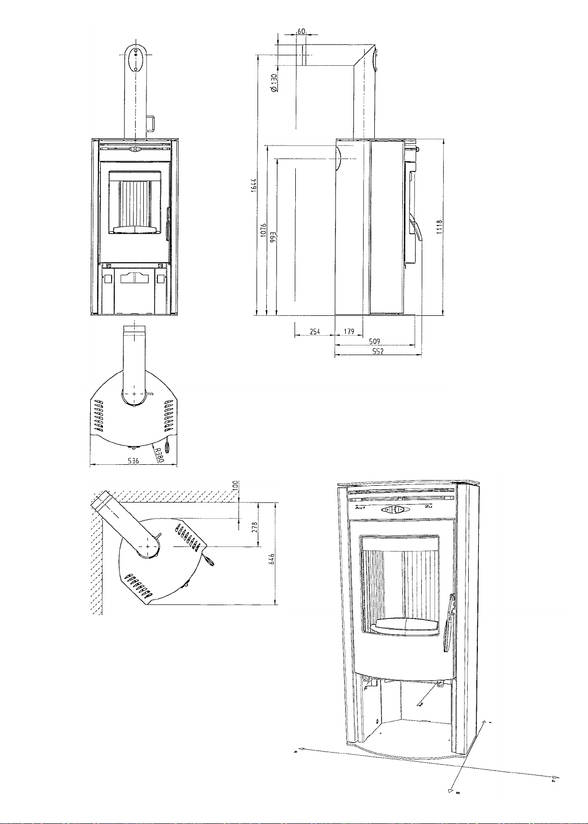
Fig. 1
Fig. 2
Page 3
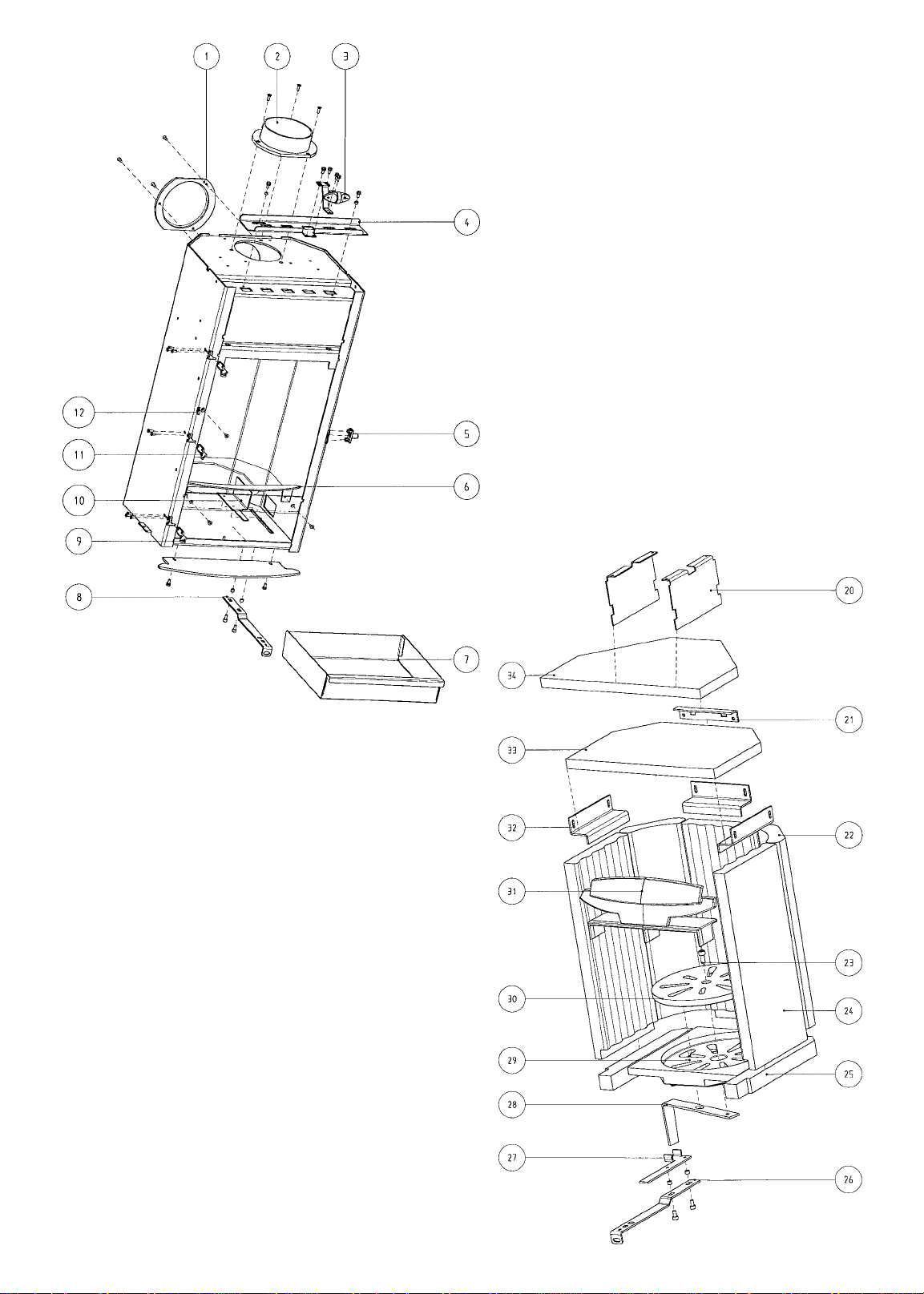
Fig. 4
Fig. 3
Page 4
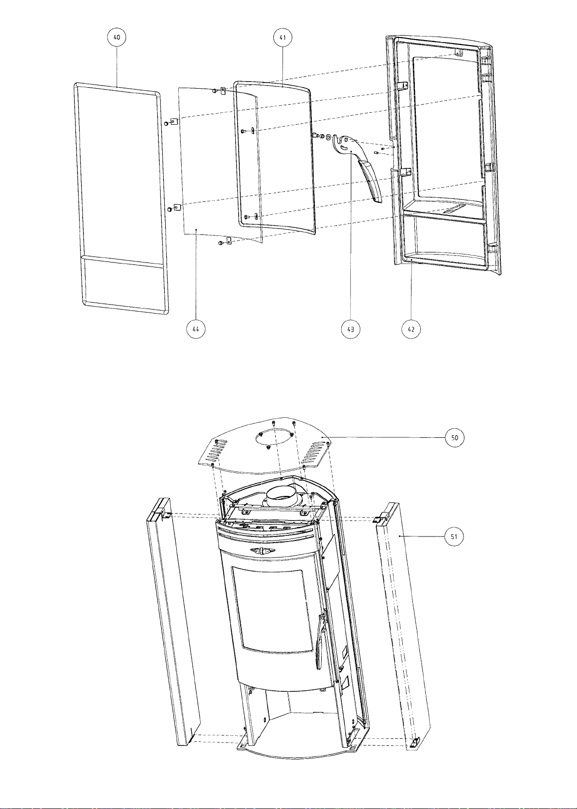
Fig. 5
Fig. 6
Page 5
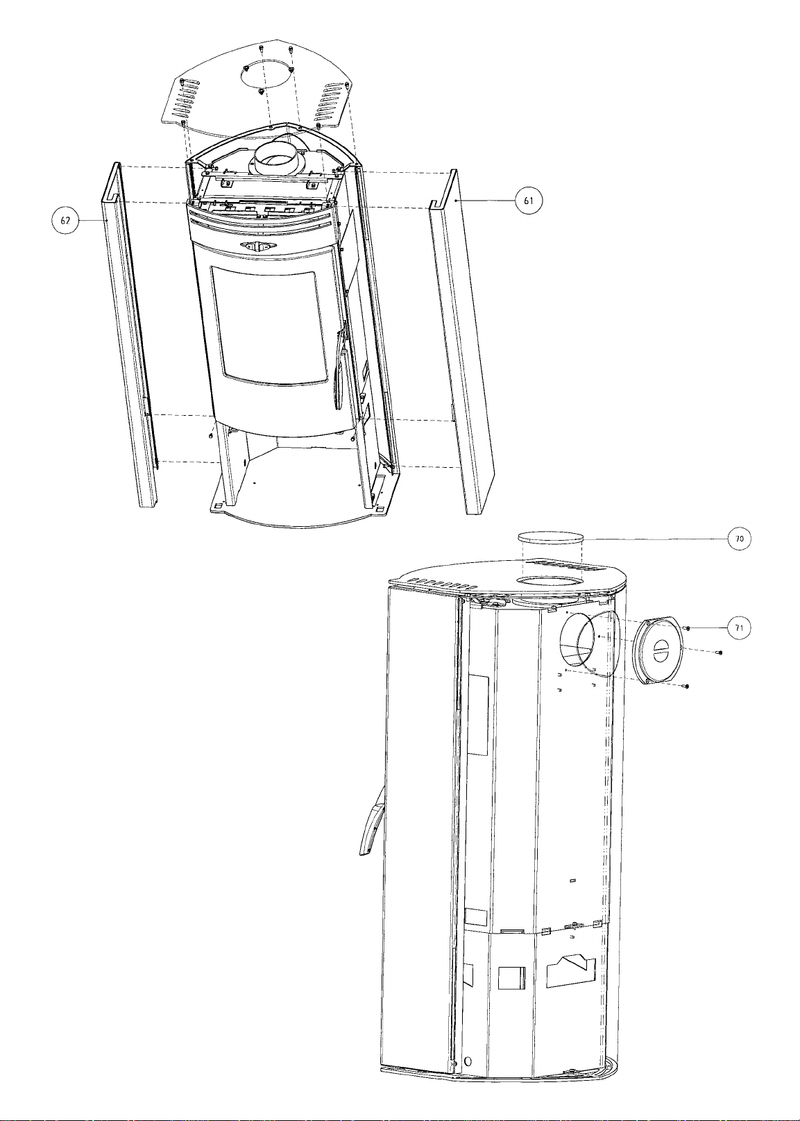
Fig. 7
Fig. 8
Page 6

EXPLANATION OF SYMBOLS
6.GUARANTEE
5.CLEANING AND MAINTENANCE
4.INSTALLATION OPTIONS
2. INSTALLATION OF THE APPLIANCE
1. IMPORTANT INFORMATION
LIST OF CONTENTS
Important instructions
Practical advice
Use the fold out plan for assistance
3.OPERATION
Overview of technical data and spare parts 19
General warning and safety instructions 20
Before installing the appliance 20 - 21
INFORMATION ON HEATING PRACTICE
Suitable fuels and quantities 22
Fuel quantities 22
Maximum fuel quantities 22
Clean combustion 23
Burning of wood 23
Changing the draw plate 24
Connecting to the chimney 24
Firing up 25
The ash drawer 26
Actuation of the vibrating grate 26
Damper settings for nominal heating performance 26
Altering the smoke tube connection from the top to the rear 27
General maintenance 28
TROUBLESHOOTING
What to do if . . . ? 29
We guarantee 55 - 56
Guarantee card 55 - 56
18
Page 7
TECHNICAL DATA
(Fig. 1)
As a domestic heater of construction type 1,
this unit can be connected to a flue that has
already been provided for use with other
ovens and hearths using solid or liquid fuels,
provided that the dimension of the flue are
not at variance with the requirements of
DIN 4705, Part 3.
The owner of the small firing equipment or
person responsible for the disposal of the
small firing equipment is required to retain
the technical documentation and to present
it on demand for inspection by the authorities or the chimney sweep.
PAC K AG I NG
Your first impression is important to us!
- The packaging of your new domestic
heater offers excellent protection against
damage. Nevertheless, damage can occur to
the heater and the accessories during transportation.
Therefore please check your heater on receipt
to ensure it is complete and free from damage!
Inform your dealer of any shortfalls without
delay!
The wood in the packaging is not surface
treated and can therefore be burnt in your
heater.
The cardboard and sheeting (PE) can be
disposed of at public refuse disposal facilities
for re-cycling.
- The packing used for your domestic
heater is largely environmentally neutral.
SPARE PARTS - OVERVIEW
(Fig. 3 to Fig. 8)
DESCRIPTION
01 Cooking plate lid
02 Smoke tube outlet
03 Secondary air slide knob
04 Secondary air slide
05 End plate
06 Ash slide
07 Ash pan
08 Control element
09 Fire door hinge
10 Primary air slide
11 Stop
12 Spring retainer
20 Air baffle plate
21 Vermiculite mount
22 Corner fire clay
23 Cylinder bolt
24 Corrugated fire clay
25 Floor fire clay
26 Control element
27 Riddle point
28 Riddle lever
29 Bottom grid
30 Riddle disk
31 Wood retainer
32 Fire clay mount
33 Bottom baffle plate
34 Top baffle plate
40 Round sealing cord
41 Sealing cord
42 Fire door
43 Fire door handle complete
44 Fire door glass
50 Lid complete
51 Side cladding stone
61 Right hand side cladding complete
62 Left hand side cladding complete
70 Insert part (connection to the rear)
71 Tapping screw with countersunk cross recess head
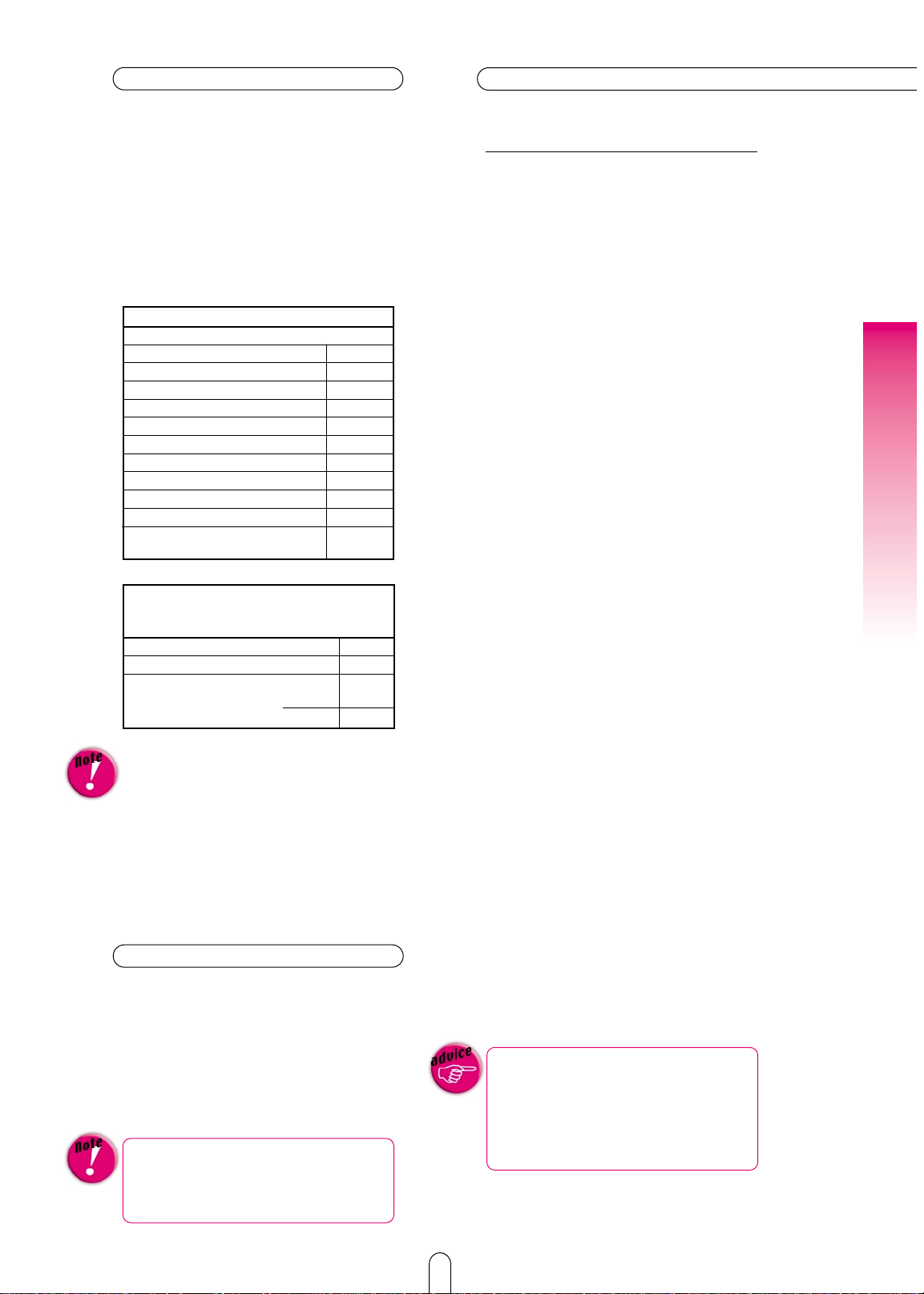
TECHNICAL DATA
Dimensions (mm) and weights (kg)
Height
Width
Depth
Weight without casing
Weight with steel casing
Weight with natural stone casing
Smoke tube outlet diameter
Nominal heating power (DIN 18891)
Maximum heating power
Lowest heating power
Space heating capacity (m
3
) -
dependent on house insulation
1118
536
552
129
140
21 3
130
8.5 kW
12.8 kW
4.3 kW
100 - 190
Exhaust gas mass flow g/s closed
Exhaust gas temperature/°C closed
Minimum delivery pressure at
Nominal heating power, mbar closed
at 0,8 x Nwl
5.7
340°
0.1 2
0.08
Exhaust gas values for multiple use of the
chimney in accordance with DIN 4705, Part 3/
chimney dimensions to DIN 4705, Part 2
ENGLISH
19
Subject to technical and optical modifications as well as typographical errors and misprints.
Page 8

1. IMPORTANT INFORMATION
GENERAL WARNING AND
SAFETY INSTRUCTIONS
The introductory general warning and
safety instructions must be unconditionally observed
➧ Before commissioning the heater, read
this handbook thoroughly in its entirety.
➧ Only an approved means of transport,
with adequate load carrying capacity must
be used to transport your heating appliance.
➧ Your heating appliance is not suitable for
use as a ladder or supporting platform.
➧ The burning of fuel releases heat energy,
leading to considerable heating of the
surface of the heating appliance, the doors,
the door and operating handles, the door
glazing, the smoke flue and in some circumstances, the front wall of the appliance
Contact with these components without
appropriate protective wear, such as heat
protective gloves, or actuating means, must
be avoided.
➧ Make your children aware of these special
dangers and ensure that they do not have
access to the appliance when it is in use.
➧ Burn exclusively the approved heating
materials stated in the section on “Clean
combustion”.
➧ The combustion or introduction of readily
combustible or explosive matter, such as
empty spray cans and the like, into the
combustion chamber, or their storage in
close proximity to the appliance is strictly
forbidden, due to the danger of explosion.
➧ No loose or bulky or easily flammable
clothing should be worn when attending
the heating process.
SAFETY DISTANCES (Minimum distances) Fig. 2
1. For non-combustible objects
a > 400 mm b > 100 mm
2. For combustible objects and supporting walls
in reinforced concrete
a > 800 mm b > 200 mm
➧ The placing of non-heat resistant objects
on or near the heating appliance is prohibited.
➧ Do not dry items of washing on the
appliance.
➧ Frames or racks for drying items of clothing,
or similar, must be placed at an adequate
distancefrom the heating appliance Danger of fire!
➧ When operating your heating appliance,
the use of easily flammable and explosive
substances in the same or an adjoining room
is prohibited.
BEFORE INSTALLING THE APPLIANCE
1 .1 Floor load capacity:
Before installing the appliance, make sure
that the load carrying capacity of the floor
sub-structure is adequate to withstand the
weight of the heater.
1 . 2 Smoke flue connection
Smoke flues are a special source of danger
in view of the poisonous gas outlet and fire
hazard. Engage the services of a franchised
dealer for their location and installation.
When connecting your flue to the heater in
the vicinity of wood clad walls, please observe
the appropriate installation guidelines.
ENGLISH
20
Page 9

1.3
Be sure to note the build-up of flue gases
under unfavourable weather conditions
(Weather inversion) and the flue draft
behaviour.
If too little air for combustion is taken in,
this can lead to fumes in the room in which
the appliance is located, or result in the
escape of flue gases. In addition, damaging
deposits can be formed in the appliance
and in the chimney.
In the event of the escape of fumes, let the
fire go out and check that all the air inlet
openings are unobstructed and that the
flue gas ducting and flue are clean. In case
of doubt, advise a registered chimney
sweep, since inadequate draft conditions
may be associated with your chimney.
1.4
Before adding new fuel, rake the existing
incandescent residue into a single bed of
material.
1.5
Only use the tool specified in our range of
accessories for the purpose of raking the
material together and ensure that no glowing
ashes fall from the combustion chamber
onto combustible material.
1.6
Brown coal briquettes, separated by about
a finger’s breadth should be laid in a single
layer on the glowing material.
1.7
When opening the doors on your appliance
and when actuating the controls, use the
tools provided with your heater for these
purposes, i.e. the protective gloves and the
operating tools.
1.8
Hea
ting appliance - Construction t
ype 1
(BA 1):
This must only be operated with the firebox door closed.
1.9
The fire box door must only be opened for
the charging of fuel and must then be closed again, otherwise this can lead to the
endangering of other fire places/heating
appliances also connected to the chimney.
1.9.1
When the appliance is not being used, the
firebox door should be kept closed.
1.10
The use of wet material as fuel, with too
much throttling, can lead to sooting-up of
the chimney, i.e. to the deposit of easily
flammable substances such as soot and tar,
possibly leading to a chimney fire.
Should this occur, close all air inlets and
flaps. Call the fire service and withdraw to a
place of safety, together with all the
occupants of the building.
Caution: Due to the size of the fire box door,
it is necessary, particularly during heating up,
when the flames are high, not to open the
door too abruptly, in order to prevent the
emergence of flames from the appliance.
21
ENGLISH
Page 10
SUITABLE FUELS AND QUANTITIES
Your appliance is basically suitable for
the burning of dry chopped firewood. In
addition, you can burn fuels such as wood
briquettes and brown coal briquettes.
Use only dry material for burning. The
burning of refuse of any kind, particularly
plastics, will damage your appliance and the
chimney and is prohibited by the statutory
regulations on emissions.
FUEL QUANTITIES
The appliance is designed with a flat firing
layout, due to its style of construction. This
means that only one layer of fuel must be
placed on the existing glowing embers
when re-charging. Please note, that if a
greater quantity of fuel is added to your
firing appliance, it will output more heat
and will heat up in excess of the intended
design limits. This may result in damage to
the appliance.
MAXIMUM FUEL QUANTITIES
Wood:
2 logs approx. 0.9 kg
Brown coal briquettes:
3 items approx. 0.5 kg
Wood briquettes (Broken):
2 items approx. 0.9 kg
Control of the power output of your appli-
ance is obtained by means of the air intake
damper. Since the power of your firing
appliance is also dependent on the chimney
draft, this air intake damper must be regulated in accordance with your own experience
of the operation of the system.
Operation of the secondary air intake regulator, the primary air intake regulator and the
vibrating grate lever, must only be undertaken
using the claw tool provided.
ENGLISH
22
INFORMATION ON HEATING PRACTICE
Page 11
Satisfying the challenges of our time
implies the acceptance of responsibility.
The conservation of nature is now one of
our greatest challenges. Our products are
developments that correspond to the latest
state of the art technology. This is an essential prerequisite for the clean, efficient
and law-abiding functioning of our firing
appliances.
CLEAN COMBUSTION
The following are important to the achievement of clean combustion:
1. THE WOOD TO BE BURNED MUST BE
DRY AND UNTREATED.
Standard value ‹ 15 % rel. humidity in the
wood.
2 - 3 years drying and well ventilated storage.
A chimney-installed firing appliance is not a
“refuse incinerator”. The burning of the refuse
and non-permitted material such as plastic,
treated wood, etc., renders the guarantee null
and void! Further consequences are damage
to and soiling of the equipment and chimney and of the environment!
2. THE CORRECT QUANTITY AND
SIZES OF WOOD FUEL
➧ Too much wood fuel results in overhea-
ting. The material is overloaded and your
appliance generates undesirable flue gas
values.
➧ Too little wood fuel, or the use of logs
that are too large, results in the firing
appliance not reaching the optimum operating temperature.
This also results in undesirable flue gas
values.
➧ Correct quantity of wood fuel:
For wood ≈ 1.6 kg (2 logs - length: 25 cm)
per charge layer (Standard value), for nominal heating power 8 kW.
Lowest heating power (4 kW) ≈ 0.8 kg
(2 logs - length: 25 cm)
Caution: Only wood briquettes and brown coal
briquettes are to be burned in your firing appliance. Under no circumstances must plastics,
treated wood materials (e.g. chipboard), pit
coal and textiles be burned.
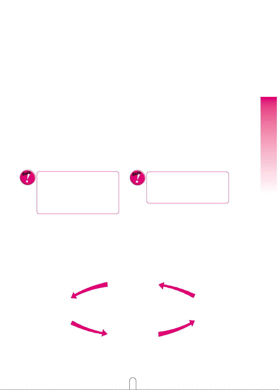
BURNING OF WOOD
The clean burning of wood corresponds to
the same chemical process as natural rotting, i.e. the liberated CO
2
(carbon dioxide)
does not increase or debit the balance of
CO
2
in the atmosphere.
Plant
Growth
Rotting of wood
Burning of wood
Wood
CO2- content
23
ENGLISH
Page 12
CHANGING THE DRAW PLATE
(Fig. 4)
If the draw plate or the draw-deflector is to
be replaced on your firing appliance, lift the
draw plate slightly to the side and remove
the side fireclay component.
You can now tilt the draw plate and remove
it from the firebox opening.
Before initial commissioning or after relocating the appliance, cleaning and servicing,
make sure that the draw plate (Fig. 4, Part 33,
34) and the wood conveyor (Fig. 4, Part 31),
are correctly positioned.
When using a flue with a throttle flap, this
must be open.
On this firing appliance, it is necessary to
ensure that the chimney draft reaches at
least the prescribed value (> 0.8 mbar).
If there is a problem in achieving this value,
contact your chimney sweep/maintenance
engineer.
CONNECTION TO THE CHIMNEY
On establishing a new connection in a
brick-built chimney, the following procedure is recommended:
1. Measure out and mark-off the position
of the chimney connection (if necessary,
taking account of the base plate thickness).
2. Chisel out (or drill out) the hole in the
masonry work.
3. Brick in the shell lining.
First seal the shell lining with mineral wool.
Then fill the area with heat-resistant mortar
or equally suitable filler.
4.When the mortar has hardened and
after the filling and smoothing, position
the base plate and floor protection
(Carton).
5. The unit can now be lifted carefully onto
the base plate.
Under no circumstances must the appliance
be pushed over an unprotected floor.
A suitable covering for the floor is provided by
using strong corrugated paper, carton or, for
example, a piece of used carpet.
The appliance can be safely pushed over such
a protective layer.
If you do not use our original flue component for the chimney connection, then we
recommend the use of a tube manufactured
from steel sheet at least 2 mm thick. Under
no circumstances must the connection
component protrude into the chimney
duct itself! Seal the gap between the flue
pipe and the shell lining with a ceramic seal.
The installation must satisfy the relevant
safety and building regulations. Please contact
your registered chimney sweep/maintenance
engineer. Who will be pleased to advise you.
ENGLISH
24
2. INSTALLATION OF THE APPLIANCE
If you use a “system” chimney (e.g. glazed
fireclay) - we would advise you to follow
precisely the connection instructions of the
manufacturer.
Page 13

FIRING UP
In order to suppress the emission of pollutants as far as possible, we would ask you for the sake of the environment - to adhere
to the following instructions for heating up
your firing appliance.
1.
If your appliance and chimney are cold, or if
low atmospheric pressure prevails, it is
recommended that initially you burn some
paper, to “drive” the coldness from the
appliance and the chimney.
2.
For the purpose of heating up, first lay
some uncoated paper on the floor of the
firebox and on top of this place 0.5 kg of
softwood chippings and 1 kg of wood (3
small logs).
Pull the vibrating grate actuator (Fig. 4, Part
26) fully out and open the primary air damper (Fig. 3, Part 8; Fig. 2) and the secondary
air damper (Fig. 3, Part 3; Fig. 2).
Please do not use gloss paper or paper from
magazines. These types of paper do not
burn well and they generate very poisonous
substances in the flue gases, due to the
coloured print.
3.
Now ignite the paper. Wait until the softwood chippings are burning well.
Several minutes later, close the vibrating
grate actuator and the primary air damper.
A few minutes later, adjust the secondary
air damper to the ideal setting.
4.
When the burning has finished, lay about
1.6 kg of wood (2 logs) in the firebox. Open
the vibrating grate actuator and the primary
air damper, until the wood is burning well
(approx. 2 min.). The secondary air damper
should remain at the ideal setting.
For each further layer of fuel, proceed in
the same way.
5.
The remnants of the combustion on the
firebox floor are the mineral components
of the wood (approx. 1 %).
This ash is an excellent fertiliser for all the
plants in the garden, because it is a purely
natural product. However, the ash should
first be left to accumulate and then be
“quenched” with water.
25
ENGLISH
3. OPERATION
Page 14
THE ENAMEL APPLIED TO YOUR HEATING
APPLIANCE BECOMES FULLY HARDENED
THROUGH HEATING DURING INITIAL USE.
- Do not touch the surface during initial
heating. It will still be soft.
- To draw off the fumes that are liberated,
ensure that the area housing the appliance
is well ventilated and do not prepare food
in the vicinity of the appliance.
- Heat up the appliance thoroughly - this will
shorten the hardening time.
- The hardenimg of the surface will be
complete after several routine heating
operations.
Please refer to Chapter 1 for details of the
wood fuel to be burned and the correct
heating procedure.
THE ASH DRAWER
In order to avoid excessive thermal stressing of the grate, the ash drawer should be
emptied regularly.
Never heat up the appliance with the ash
drawer open → Danger of over heating →
Guarantee is rendered null and void.
Caution: Burning embers can still be present
in the ash. Therefore only empty the ash into
a non-flammable container and do not place
the ash drawer on flammable surfaces.
ACTUATION OF THE VIBRATING
GRATE
The translatory motion of the vibrating
grate actuator causes the ash to be transfered from the combustion chamber to the
ash drawer.
This leaves the path clear in the combustion chamber for primary air - necessary for
the heating-up phase.
It is not necessary to activate the vibrating grate during the heating-up phase.
DAMPER SETTING FOR NOMINAL
HEATING PERFORMANCE
Fuel
Wood/
Wood briquettes
Brown coal
briquettes
Primary air
Secondary air
Vibrating grate
Closed
1/3 open
Closed
1/2 open
1/4 open
Open
The setting “Primary air fully open” must
only be used as a heating-up setting.
ENGLISH
26
Page 15

4. INSTALLATION OPTIONS
EGNLISH
27
ALTERING THE SMOKE TUBE
CONNECTION FROM THE TOP
TO THE REAR
(Fig. 8)
1. Remove the lid (Fig. 6, Part 50) from your
stove.
2.Cut out the pre-stamped round section
in the rear wall (Fig. 8) (Elsen saw disk).
3.Exchange the smoke tube outlets (Fig. 3,
Part 2) (3 x cross slit screws + washers +
nuts) and cooking plate lid (Fig. 3, Part 80;
Fig. 8) (3 x cross slit screws).
4.Now replace the lid on your stove.
5. Put the insert in place for rear connec-
tion (Fig. 8, Part 70). As shown in Fig. 8.
Page 16
5. CLEANING AND MAINTENANCE
GENERAL MAINTENANCE
Your TANGO appliance has been designed
by our development team with the concepts of minimum maintenance and long
operating life very much in mind. Certain
cleaning operations and the checking of
seals are necessary from time to time. The
time between inspections depends to a
large extent on the quality of the wood you
burn and frequency of use.
All maintenance and cleaning work must be
undertaken exclusively when the appliance
has completely cooled down.
A REMINDER
Only use wood that has been properly
stored, is dry and untreated.
Use the correct quantity of fuel.
Poor fuel material can more than double the
number of maintenance activities that become
necessary.
SURFACE CONDITION AND
CLEANLINESS
The glass in the doors can be cleaned with
a specially prepared cleaning medium. This
is obtainable from your specialist dealer. If
the glass becomes very severely sooted,
this could be caused through burning damp
wood.
The grey surface of the appliance is highly
heat-resistant and need only be cleaned
using a cloth (dampened if necessary). If
the surface needs to be restored, then use
only the original type of lacquer as stocked
by your specialist dealer.
CONVECTION AIR OPENINGS
Clean off dust deposits from the convection air openings regularly, using a source of
suction.
Before the start of a new heating season,
the appliance should be thoroughly cleaned
in order to avoid excess odours during
operation.
CLEANING THE FLUE GAS PATHS
(Once per year)
Remove the fire tubes.
Brush off/suck out any deposits of soot
and dust in the firing components and the
fire tubes.
At the start and finish of a heating period,
check the seals on the combustion chamber door and on the ash drawer.
If the seals are damaged or very worn, then
please order the appropriate replacement
items.
ENGLISH
28
Only intact seals will guarantee the proper
functioning of your firing appliance. Loose
seals should be reattached using Thermohit
seal adhesive.
Page 17

TROUBLESHOOTING
1. Ceramic glass
pane soots up
too quickly
2. Appliance does not
draw properly
3. Appliance does not
burn properly
4.Appliance smells
strongly and there
is smoke outside
5. Lacquer does not
harden
6. Escape of fumes on
relaying and during
the heating phase
What to do if ...?
Problem Reason Solution
➧ Poor draft
➧ Incorrect regulation
➧ Too much fuel
➧ Wet wood
➧ Wrong fuel
➧ Chimney draw is inadequate
➧ Appliance is sooted up inside
➧ Weather influence
➧ Incorrect heating up
➧ Burning-in phase
➧ Appliance is dusty/dirty
➧ Burning-in phase not
completed properly
➧ Chimney draw inadequate,
flue connection not sealing
Basically: From time to time (depending on usage), each glass
pane must be cleaned using a special
glass cleaner (e.g. the “Thermohit”
brand)
Discuss with chimney sweep/maintenance engineer (if necessary raise
the chimney or fit a chimney cap).
Adjust the air damper in accordance
with the operating instructions (if
the secondary air is closed-off, the
glass pane will soot up very quickly,
but under normal specified operating conditions, it may burn off
again)
See item “Max. fuel quantities”
See item “Clean combustion” - if
necessary, use wood briquettes (these
are uniformly dry)
or: The glass panes dirty quicker when
using coal briquettes, than when using
wood
See item ”Inform. on heating practice.”
See item “Cleaning and maintenance”
See item “Firing up”
See item “Firing up”
See item “Operation” (Hardening of
the lacquer)
See item “Convection air openings”
See item “Operation” (Hardening of
the lacquer)
Check connections and re-seal if
necessary
ENGLISH
29
If, after referring to this troubleshooting guide, your problem persists, contact your specialist dealer or
registered chimney sweep/maintenance engineer.
Page 18

GARANZIA/GARANTIE
Kunde/Customer/Cliente/Client
An/To/A/A
Marke
Stamp
Marca
Marque
COSA GARANTIAMO
5 anni per un funzionamento corretto di tutte le parti in
acciaio. La garanzia include difetti di materiale e di lavorazione. Condizione fondamentale alla prestazione di garanzia è la corretta installazione ed il corretto funzionamento
dell’apparecchio, conformemente al presente manuale d’istruzioni. L’allacciamento deve essere effettuato da un
tecnico specializzato.
Sono esclusi dalla garanzia:
PARTI SOGGETTE AD USURA COME:
➧ Vetro
➧ Vernice
➧ Rivestimenti sulla superficie
(per es. su maniglie, diaframmi)
➧ Guarnizioni
➧ Griglia di fondo
➧ Mattonelle refrattarie
➧ Ceramich e
➧ Pietre naturali
DANNI, originati dalla mancata osservanza delle direttive
del produttore riguardo il funzionamento dell’apparecchio
(per es. surriscaldamento, combustione di materiale non
idoneo, ecc.)
La RICHIESTA DI GARANZIA deve essere documentata
dalla ricevuta e dal tagliando di garanzia compilato in ogni
sua parte. La SOSTITUZIONE IN GARANZIA include la
consegna gratuita di parti di ricambio. La manodopera e la
trasferta non sono coperte dalla garanzia del produttore.
Tutti gli altri eventuali costi (per es. trasporto, riparazione,
ecc.) che il produttore deve sostenere in seguito ad una
richiesta di garanzia non legittima, verranno addebitati
all’utente.
NOUS GARANTISSONS
Nous garantissons pendant 5 ans la fonction irréprochable
de tous les composants en acier. La garantie englobe les
défauts de matériel et de fabrication. La condition pour la
prestation de garantie est que l’appareil ait été installé et
mis en service conformément au présent manuel. Le
raccordement doit être effectué par un spécialiste.
Sont exclues de la garantie:
Les PIECES D’USURE comme
➧ Le verre
➧ Le vernis
➧ Les revêtements de surface (par ex. sur les poignées,
caches)
➧ Les joints
➧ La grille au sol
➧ Les chamottes
➧ Les céramiques
➧ Les pierres naturelles
Les ENDOMMAGEMENTS causés par le non-respect des
prescriptions du fabricant sur l’utilisation de l’appareil (par
ex. surchauffe, combustion de matériaux non appropriés, ...).
Le droit à la garantie doit être prouvé par la présentation
de la facture et de la carte de garantie entièrement
remplie. Le REMPLACEMENT EN GARANTIE comprend la
livraison gratuite des pièces de rechange. Le temps de
travail et de déplacement ne sont pas acquittés par la
garantie du fabricant.
Tous les coûts éventuels (par ex.: transport, réparation, ...)
occasionnés au fabricant par un recours injustifié à la
garantie sont facturés à l’utilisateur.
Z. Nr. 2193-0200-0000
Art. Nr. Z30 670
Prod.-Nr. 6/2001
Page 19

WIR GARANTI EREN
5 Jahre für eine einwandfreie Funktion von allen Bauteilen
aus Stahl. Die Garantie umfaßt Defekte an Material und
Verarbeitung. Voraussetzung für die Garantieleistung ist,
daß das Gerät gemäß vorliegendem Handbuch installiert
und betrieben wurde. Der Anschluß muß durch einen entsprechenden Fachmann erfolgen.
Ausgenommen von der Garantie sind:
VERSCHLEISSTEILE wie
➧ Glas
➧ Lack
➧ Oberflächenbeschichtungen (z. B. auf Griffe, Blenden)
➧ Dichtungen
➧ Bodenrost
➧ Schamottsteine
➧ Keramiken
➧ Natursteine
SCHÄDEN, die durch Nichtbeachtung der
Herstellervorschriften zum Betrieb des Gerätes entstehen
(z. B.: Überhitzung, Verbrennung von ungeeigneten
Materialien, ...)
Der GARANTIEANSPRUCH ist durch Rechnung und vollständig ausgefüllte Garantiekarte nachzuweisen. Der
GARANTIEERSATZ umfaßt die kostenlose Lieferung von
Ersatzteilen. Arbeitszeiten und Wegzeiten werden nicht
durch die Herstellergarantie abgegolten.
Alle etwaigen Kosten (z. B.: Transport, Reparatur, ...) die
dem Hersteller durch eine ungerechtfertigte Garantieinanspruchnahme entstehen, werden dem Betreiber rückbelastet.
GARANTIE/GUARANTEE
Händlerstempel/Dealers stamp/Timbro del rivenditore/
Cachet du revendeur:
angeschlossen von/Installed by/Allacciato da/Raccordé le:
Kaufdatum/Date of purchase/Data d’acquisto/Date d’achat:
Modellname/Name of model/Nome modello/Nom du modèle:
Nummern des Typenschildes auf der Ofenrückseite:
Number of the type plate on the rear of the appliance:
Numeri della targa modello sul retro della stufa:
Numéros de la plaque signalétique à l’arrière du poêle:
Hersteller No./Manufacturer No./Nr. produttore/N° de fabricant:
Serien No./Serial No./Nr. serie/N˚ de série:
✃
WE GUARANTE E
5 years unimpared functioning of all steel components.
The Guarantee includes material defects and defective
treatment. A condition of this Guarantee is that the appliance has been installed and operated in accordance with
this handbook. The connection must be carried out by an
appropriate specialist.
The following are excluded from the guarantee:
PARTS SUBJECT TO WEAR, such as
➧ Glass
➧ Lacquer finish
➧ Surface coating (e.g. on handles)
➧ Seals
➧ Floor grate
➧ Fireclay bricks
➧ Ceramics
➧ Natural stone
DAMAGE caused by non-observance of the manufacturer’s
instructions for operation of the appliance (e.g. Overheating, burning of unsuitable materials, etc.)
GUARANTEE CLAIMS are to be supported by production
of the invoice and the fully completed guarantee card.
The GUARANTEE covers the free delivery of spare parts.
Working hours and travelling time are not covered by the
Manufacturer’s Guarantee.
All costs (e.g. transport, repairs, etc.) incurred by the
manufacturer due to an unjustified Guarantee claim are
borne by the operator.
 Loading...