

Page 1
Operating Manual
MEMO
Page 2

TABLE OF CONTENT
1. PREFACE 3
Explanations to symbols ...........................................................................................................................................................................3
Spare part overview exploded diagram .....................................................................................................................................................4
Spare part overview article numbers .........................................................................................................................................................6
Dimensions ..............................................................................................................................................................................................7
Technical data ...........................................................................................................................................................................................7
Amount of fuel .........................................................................................................................................................................................7
Packaging .................................................................................................................................................................................................7
Electrical connection ................................................................................................................................................................................7
2. IMPORTANT INFORMATION 8
General warning and safety information ..................................................................................................................................................8
Safety distances ........................................................................................................................................................................................8
Prior to set up ...........................................................................................................................................................................................9
e correct chimney connection ...............................................................................................................................................................9
3. BRIEF INFORMATION ON FUEL - PELLETS 10
What are pellets? ....................................................................................................................................................................................10
Wood pellet specification according to ENplus – A1 .............................................................................................................................10
Pellet storage ..........................................................................................................................................................................................10
4. TECHNOLOGY AND SAFETY FUNCTIONS 11
Operating comfort ..................................................................................................................................................................................11
Top efficiency - lowest emissions ............................................................................................................................................................11
Overheating ............................................................................................................................................................................................11
Low-temperature shutdown ...................................................................................................................................................................11
Electrical excess current protection .........................................................................................................................................................11
Component monitoring .........................................................................................................................................................................11
Power failure (during heating) ................................................................................................................................................................11
Power failure (during the initial stage)....................................................................................................................................................11
5. INSTALLING THE STOVE 12
General information ...............................................................................................................................................................................12
Connection to the chimney ....................................................................................................................................................................12
Connecting to a steel chimney ..............................................................................................................................................................12
Combustion air .......................................................................................................................................................................................12
Feeding in external combustion air .........................................................................................................................................................12
6. ASSEMBLY/DISMANTLING STONE AND OPTIONS 13
Disassembly of the front side casing.......................................................................................................................................................13
7. INTERNAL CONTROLS 14
Basics ......................................................................................................................................................................................................14
Operation ...............................................................................................................................................................................................14
EASY MODE - simple heating operation ...........................................................................................................................................14
EASY OFF - inactive state ....................................................................................................................................................................14
Start - scavenge - tip - ignition ..............................................................................................................................................................14
Stopping during ignit or startphase ........................................................................................................................................................15
EASY 40 – operation .............................................................................................................................................................................15
Cleaning and tipping during operation ..................................................................................................................................................15
EASY 40 – switch off .............................................................................................................................................................................15
Extended heating operation - HEAT MODE - comfort funktions ......................................................................................................16
Menu structure and main menu level .....................................................................................................................................................17
Main menu time - time adjustment .......................................................................................................................................................18
Main menu setup - additional functions ................................................................................................................................................20
Main menu info - additional information ..............................................................................................................................................22
8. COMFORT OPTIONS 24
RIKA room sensor/RIKA radio room sensor .........................................................................................................................................24
RIKA phone option – GSM ..................................................................................................................................................................24
Page 3

|
3
EN
2
1. PREFACE
Explanations to symbols
...important
note
#8
...hex #8
(M5 winding)
3
...allen key #3
(M4 winding)
...useful
tip
#10
...hex #10
(M6 winding)
...manually
RIKA interface for various options .........................................................................................................................................................24
External room thermostat ......................................................................................................................................................................24
External connection cable bridge ...........................................................................................................................................................24
9. MODES 25
Pellet operation Heat/Easy/Automatic/Room .......................................................................................................................................25
Fuel addition pellet operation .................................................................................................................................................................25
Emergency - electrical heating up. without ignition ...............................................................................................................................25
10. MENU OVERVIEW V1.40 26
11. WARNINGS AND ERROR MESSAGES 28
12. CLEANING AND MAINTENANCE 29
Basic information ...................................................................................................................................................................................29
Open the combustion chamber door ......................................................................................................................................................29
Cleaning the fire trough .........................................................................................................................................................................29
Ampty the ash drawer ............................................................................................................................................................................29
Cleaning flue pipes .................................................................................................................................................................................30
Clean flue gas collecting channel ............................................................................................................................................................31
Clean flue gas fan housing ......................................................................................................................................................................31
Cleaning the flame temperature sensor .................................................................................................................................................31
Combustion air - intake .........................................................................................................................................................................31
Cleaning the pellet container ..................................................................................................................................................................31
Cleaning the door glass ..........................................................................................................................................................................31
Bearings .................................................................................................................................................................................................31
Checking door seal .................................................................................................................................................................................31
Checking chimneay connection ..............................................................................................................................................................31
13. PROBLEMS - POSSIBLE SOLUTIONS 32
Problem 1 ...............................................................................................................................................................................................32
Problem 2 ...............................................................................................................................................................................................32
Problem 3 ...............................................................................................................................................................................................32
14. INSTRUCTIONS FOR COMMISSIONING PROTOCOL 33
15. GUARANTEE 35
Page 4
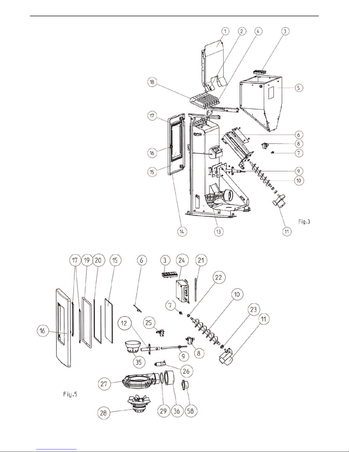
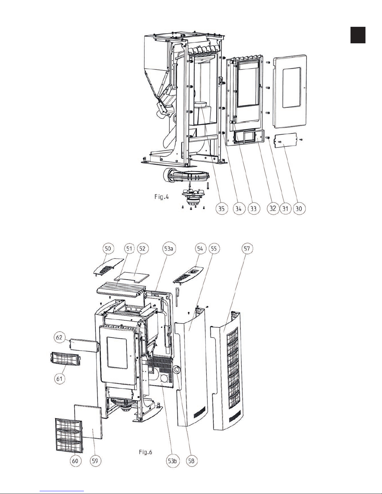
Spare part overview exploded diagram
Page 5
|
5
EN
4
Page 6

Spare part overview article numbers
# Art.Nr.: Description
1 B15245 heat protection compl.
2 Z31459 sensor clamp
3 B16521 Control panel
4 L00426 Flue plate
4*** L02585 Flue plate
5 B15782 container compl.
6 N111515 flame sensor
6*** B16114 Temperature sensor
*** B16053 sensor tube
*** L01441 Pressure bracket
7 N107887 fuse holder
8 N111586 safety temperature limiter
9 Z32147 ignition cartridge
10 B12301 screw
11 B15773 auger motor 220V/50Hz
11*** N111820 Screw motor, stepless
12 B15781 HP bracket
13 B15587 fan compl.
14** Z32344 combustion chamber door compl.
B15249
combustion chamber door compl. until Snr.
1301733
15 Z32340 door glas
16 Z34857 Locking bolt
L02220 lock tongue
B15313 door handle complete until Snr 1301733
N111576 Switch cabinet key
17 L00437 glass holder
18 B15244 combustion chamber lid compl.
18*** B16321 Combustion chamber cover metallic grey
18*** B16052 Combustion chamber cover black
19 N100485 Round sealing strip D12
20 N103693 culimeta flat packing black 8x2
21 Z30493 door handle chrome
22 Z35183 Sintered bearing Di10
23* Z35182 Plastic bearing
24 B16270 main board
24*** B15856 Motherboard C2 (for control panel)
25 N111825 door contact switch
26 N111597 capacitor
27 B16155 Induced draft fan housing
28 N111581 induced draught fan motor
29 N108315 O-ring D76/4.5
30 Z32422 cleaning opening metallic
31 N100055 hexagon socket screw
32 B15243 combustion chamber front compl.
33 B14478 Hinge BA1
34 N106591 cage nut electro-galvanised, cage NR M8
35 Z32345 fire trough
36 Z18502 pipe adapter
37 B15800 Cabletree
37*** Z34546 Cabletree
50 L01018 cover left compl.
51 B16020 convection fin compl.
52 L01021 container lid
53a L01016 rear wall top
53b L01025 rear wall bottom
*** LB00620 rear wall metallic
*** LB00621 rear wall black
54 L01017 cover right compl.
55 LB00441 casing right, cast grey
58 Z18278 air intake
59 Z32424 casing front/bottom, silver
# Art.Nr.: Description
62 Z35705 casing front/top silver
65 LB00442 casing left cpl., cast grey
L00797 motor plate
*** B16030 additional board
**
up to serial number 1301733 the firebox
door completely (B15249) must be supplied
as a spare part when replacing the firebox
door. In addition (111576) is required when a
Türtasuch the cabinet key.
*** from serial number 1328866
Page 7
|
7
EN
6
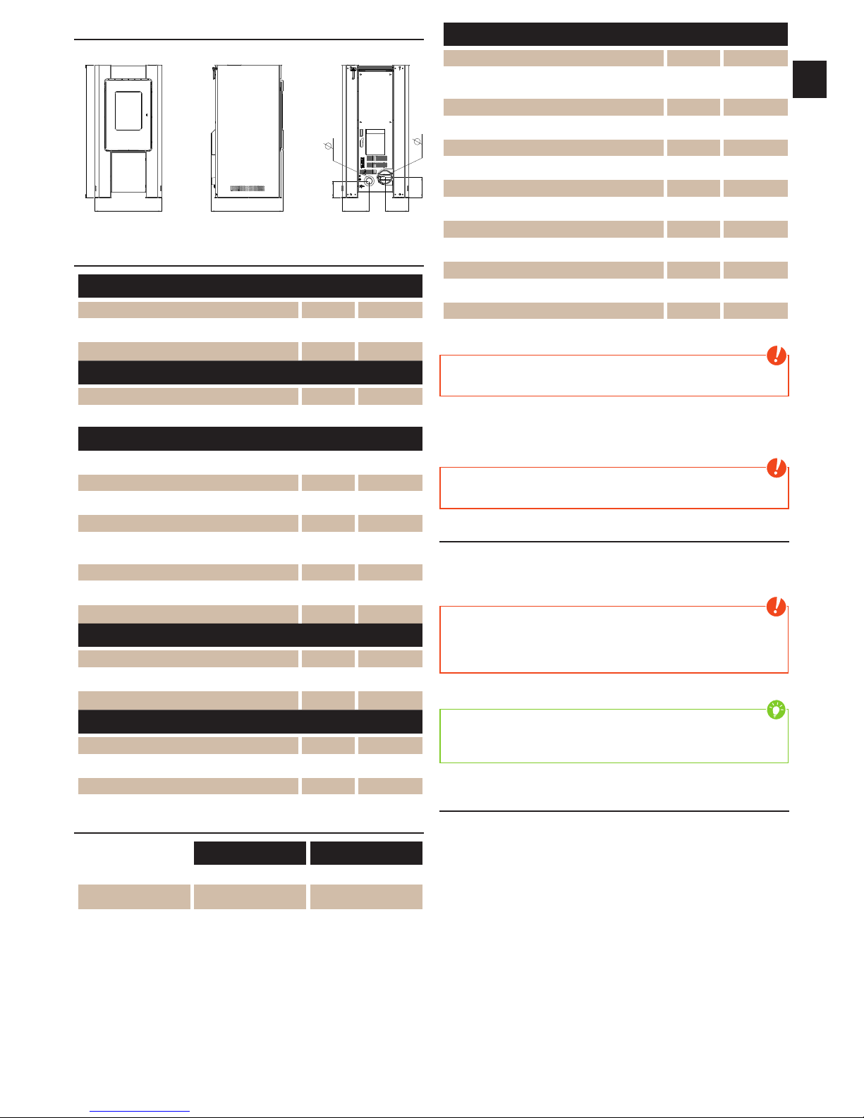
Dimensions
B
H
T R-S
R-H
F-S
F-H
R-
F-
Technical data
Dimensions
height [mm] 978
width [mm] 490
corpus depth [mm] 544
Weight
weight without shell [kg] 95
weight with shell [kg] 110
Flue pipe connection
R - Ø flue pipe outlet [mm] 100
RO - H original angle pipe connection height [cm] RO - T1 original angle pipe total depth [cm] RO - T2 original angle pipe distance to rear wall [cm] -
RO - T3 deapth from rear wall to middle of flue
pipe
[cm] -
RO - S original angle pipe side distance [cm] R - H rear connection height [cm] 15
R - S rear connection side distance [cm] 17
Fresh air connection
F - Ø diameter [mm] 50
F - H connection height [cm] 12
F - S side distance [cm] 20
Convection air connection
K - Ø diameter [mm] K - H connection height [cm] K - S side distance [cm] -
Amount of fuel
nominal load part load
Amount of fuel ~2,2kg* ~0,6kg*
Burn time at full pellet
hopper
ca. 11h ca. 28h
*Practical values may vary depending on pellet quality.
Technical data
heating power range [kW] 2,4 - 9
room heating capacity (depending on house
insulation)
[m³] 50 - 240
fuel consumption [kg/h] bis 2,2
pellet container capacity [kg] 21
electric supply [V]/[Hz] 230/50
average electrical input [W] ~ 20
fuse [A] 2,5 AT
Efficiency [%] 92,1
CO2 [%] 11,1
CO-emission on 13% OO [mg/m
N
3
] 34
dust emission [mg/m
N
3
] 22
exhaust [g/s] 6,45
exhaust temperature [°C] 144
chimney draft requirement [Pa] 0
Note
Pellet consumption depends on the size of the pellets. The larger the pellet,
the slower the feed and vice versa
The owner of small firing systems or the person authorised for the small
firing system is to keep the technical documentation and is to submit it to the
authorities or the chimney sweep on request.
Note
Please observe the national and European standards as well as local
regulations concerning the installation and operation of firing installations!
Packaging
Your first impression is important to us!!
The packaging of your new stove provides excellent protection against damage.
However damage to the stove and accessories may still occur during transport.
Note
Therefore please check your stove on receipt for damage and completeness!
Report any deficiencies to your dealer immediately! Pay particular attention
during unpacking that the stone panels remain intact. Scratches to the
material can easily occur. Stone panels are excluded from the warrant
The packaging of your new stove is environmentally neutral to a great extent
Tip
The wood used in the packaging has not been surface treated and may
therefore be burnt in your stove. The cardboard and film (PE) can be disposed
of via the municipal waste collection for recycling
Electrical connection
The stove is supplied with an approx. 2m long connecting cable with a Euro-plug.
This cable is to be connected to a 230Volt/50Hz socket. The average electrical
power consumption is some 20 Watt in heating operation. And approx. 150
Watt during automatic ignition. The connection cable must be laid so that there
is no contact to any sharp edges or hot surfaces of the stove.
Page 8
2. IMPORTANT INFORMATION
General warning and safety information
Observance of the introductory general warning information is imperative.
Q Read the entire manual thoroughly before installing and putting the stove into
service. Observe the national provisions and laws as well as the regulations
and rules applicable locally.
Q RIKA stoves should only be installed in rooms with normal humidity (dry
areas according to VDE 0100 Part 200). The furnaces are not splash water
protected and may not be installed in wet areas.
Q Only approved transport equipment with sufficient load carrying capacity
may be used with your heating appliance.
Q Your heating appliance is not suitable for use as a ladder or stationary
scaffolding.
Q The burning of fuel releases heat energy that lead to extensive heating of
the stove surfaces, doors, door and operating handles, glass, flue pipes
and possibly the front wall. Refrain from touching these parts without
appropriate protective clothing or equipment e.g. heat-resistant gloves or
means of operation (operating handle).
Q Make your children aware of this particular danger and keep them away from
the stove during heating.
Q Only burn approved heating materials
Q The combustion or introduction of highly flammable or explosive materials
such as empty spray cans etc. in the combustion chamber and storing them
near the stove is strictly prohibited due to the danger of explosion.
Q No light or inflammable clothing is to be worn when post-heating.
Q Placing non-heat resistant objects on the stove or near it is prohibited.
Q Do not place clothing on the stove to dry.
Q Stands for drying clothes etc. must be placed at a sufficient distance to the
stove – ACUTE DANGER OF FIRE!
Q When your stove is burning, the use of highly inflammable and explosive
materials in the same or adjacent rooms is prohibited
Note
Waste and liquids may not be burnt in the stove!
Note
To prevent your stove from overheating of the internal components,
do never cover the convection fins!
Safety distances
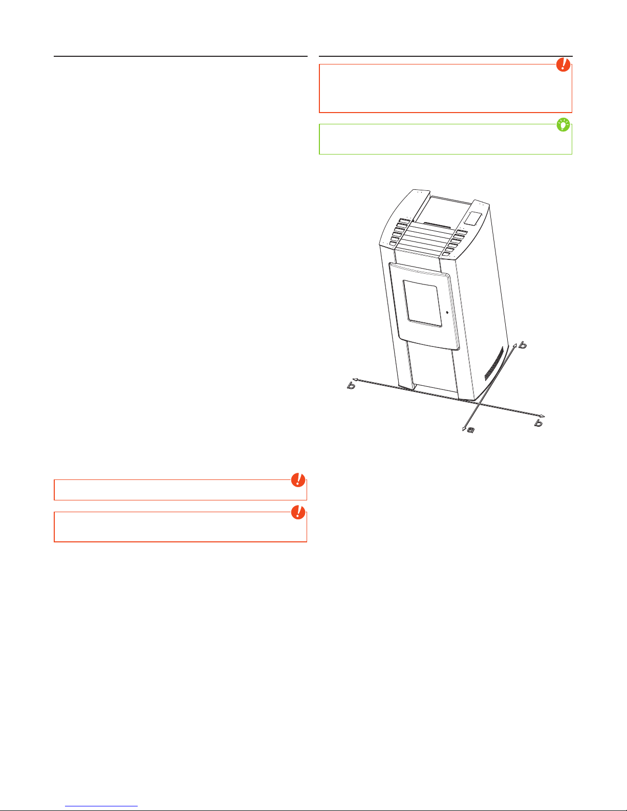
Note
1. To non-combustible objects
a > 40 cm b > 10 cm
2. To combustible objects and reinforced concrete load-bearing walls
a > 80 cm b > 20 cm
Tip
please observe a minimum distance of 20 cm behind and sideways the stove
for maintenance.
Page 9
|
9
EN
8
Prior to set up
Floor bearing capacity
Ensure that the substructure is capable of bearing the weight of the stove prior
to set-up.
Note
No modifications may be made to the firing installation. This also leads to loss
of warranty and guarantee.
Floor protection
A base is required (glass, sheet steel or ceramic) if the floor is combustible
(wood, carpet, etc.).
Flue pipe connection
Q Flue pipes pose a particular source of hazard regarding gas leaks and
fire. Get the advice of an authorised specialist company for the layout and
assembly.
Q Please observe the corresponding installation guidelines for walls panelled
with wood when connecting your flue pipes to the stove,
Q Observe the formation of flue gas (atmospheric inversion) and draughts
when the weather is unfavourable.
Q Infeed of too little combustion air can lead to smoke in the rooms or to flue
gas leaks. Hazardous deposits in the stove and chimney may also occur.
Q If flue gas escapes, let the fire burn out and check whether all the air inlet
openings are free and the flue gas pipes and the stove pipe are clean. If in
doubt notify the master chimney sweep since draught malfunctions may be
connected to your chimney.
Q Only use suitable tools from our range of accessories when handling embers
and make sure that no embers fall out of the combustion chamber onto
inflammable material.
Q Use the heat-resistant gloves supplied to open the doors of your stove.
The correct chimney connection
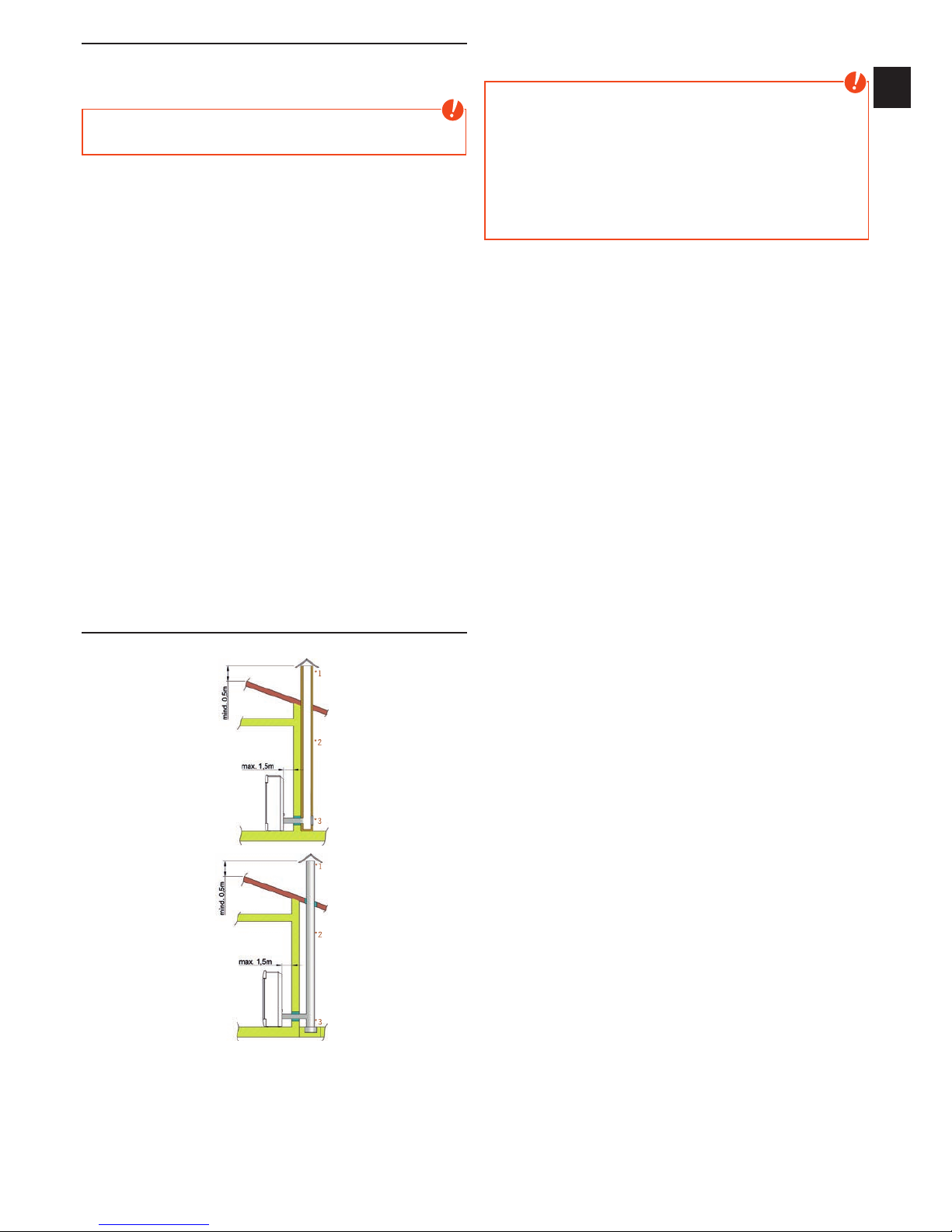
There are several ways to connect your stove to the chimney, eg:
*1
*2
*3
*1
*2
*3
1) wind break, 2) chimney, 3) inspection opening
For the selection of the connection and to ensure a proper connection between
the stove and chimney, please read the guide „INSTALLING THE STOVE“ or ask
your local chimney sweep.
Stoves type 1 (BA 1):
Q Suitable for multiple occupancy. (note the different country regulations)
Note
on ROOM-AIR DEPENDENT and
ROOM-AIR INDEPENDENT OPERATION:
Your stove has been tested as a room-air dependent stove according to EN
14785 and does not conform in Germany to the requirements for roomair independent operation. In combination with room-air installations (e.g.
controlled ventilation and venting systems (extractors etc.) it must be ensured
that the stove and the room air system are monitored and safeguarded
mutually (e.g. via a differential pressure controller etc.). The combustion air
infeed of approx. 40 m3/h must be ensured. Please observe the respective
local regulations and rules in consultation with your master chimney sweep
Page 10
3. BRIEF INFORMATION ON FUEL - PELLETS
What are pellets?
Wood pellets are a standardised fuel. Every manufacturer must adhere to certain
conditions in order to enable flawless, energy-efficient heating. Pellets are made
from wooden waste, from sawmills and planning workshops, as well as from
residue from forestry operations. These “starting products” are crushed, dried,
and pressed into Pellet “Fuel” without any bonding agent.
ENplus – Pellets
This new pellets are a standard sets new benchmarks in the European pellet
market. The traceability of pellets is ensured thanks to the use of identification
numbers. The pellet manufacturers’ production facilities and manufacturing
processes are reviewed every year. A quality assurance system ensures
the pellets comply with the requirements of the new standard and that the
conditions for trouble-free heating are guaranteed
Wood pellet specification according to ENplus –
A1
parameter measure ENplus-A1
diameter mm 6 (±1)
2)
length mm 3,15 bis 40
3)
buld density kg/m³ ≥600
calorific value MJ/kg ≥16,5
water content Ma.-% ≤10
fine fraction (<3,15mm) Ma.-% ≤ 1
mechanical rigidity Ma.-% ≥97,5
4)
ash content Ma.-%
1)
≤0,7
ash softening temperature (DT) °C ≥1200
chlorine content Ma.-%
1)
≤0,02
sulphur content Ma.-%
1)
≤0,03
nitrogen content Ma.-%
1)
≤0,3
copper content mg/kg
1)
≤10
chrome content mg/kg
1)
≤10
arsenic content mg/kg
1)
≤1
cadmium content mg/kg
1)
≤0,5
mercury content mg/kg
1)
≤0,1
lead content mg/kg
1)
≤10
nickel content mg/kg
1)
≤10
zinc content mg/kg
1)
≤100
1) in an anhydrous state
2) diameter must be specified
3) a maximum of 1% of the pellets may be longer than 40 mm,
max. length is 45 mm
4) the limit value of ≥97,7 Ma.-% applies when conducting measurements with a
lignotester (internal control)
Note
Please ask your pellet stove dealer for tested fuel and a list of monitored fuel
manufacturers.
Using poor quality or prohibited pellet fuel will have a negative effect on the
function of your pellet stove and can also lead to the warranty becoming null
and void, as well as the product liability connected with this. Observe waste
incineration legislation!
Only burn pellets that have been inspected according to ÖNORM, DIN Plus
or ENplus-A1.
Pellet storage
In order to guarantee problem free burning of the wooden pellets, it is imperative
necessary to store the fuel as dry as possible and free from impurities.
Pellets should not be kept in sacks outdoors or stored in a manner where
they are exposed to the environment. This can lead to blockages in the screw
conveyor
Note
“screw stoppers” are excluded from the warranty.
Note
Your pellet stove is only approved for the burning of wood or pellets of
tested quality. Burning straw, maize, woodchips etc. is not permitted! Nonobservance of these regulations makes void all warranty and guarantee
claims and may impair the safety of the unit!
Page 11
|
11
EN
10
4. TECHNOLOGY AND SAFETY FUNCTIONS
The technological advances in your new combi stove are the result of years of
testing and practical experience. The practical advantages of your pellet stove
are convincing:
Operating comfort
The microprocessor-controlled combustion regulation optimises the interaction
of flue gas blower and screw using the current combustion chamber
temperature. This guarantees optimum combustion and operating status.
All function can be regulated centrally using the integrated operating unit. The
intuitive graphic interface permits easy operation; all the settings can be made
quickly and simply.
Top efficiency - lowest emissions
A very great heat exchange surface together with optimum combustion air
control leads to excellent fuel utilisation.
Fine continuous pellet dosing in an optimised burner pot made of high-quality
grey cast iron leads to virtually complete combustion with very good exhaust
gas values - and this is guaranteed in every operating phase.
Note
The automatic control system means that during operation, the flame noise,
pellets dropping and actuation of the electronic components permissible for
living spaces are audible.
Overheating
A safety temperature limiter (STL) switches the stove off automatically on
overheating. Once the stove has cooled, the STB at the stove rear must be
unlocked manually (pressed). The stove is ready for operation again after
acknowledging the error message at the internal unit.
Note
Maintenance and cleaning work must be performed if overheating occurs! If
this error recurs, operation without danger is no longer guaranteed; notify
customer service immediately.
Low-temperature shutdown
The unit switches off if the stove cools below a minimum temperature. This
switch-off may occur if pellet ignition is delayed.
Electrical excess current protection
The stove has a main fuse (at the rear) to protect against excess current
Component monitoring
All the electrical components used are continuously monitored during operation.
If a component is defective or can no longer be actuated correctly, then
operation is stopped and a warning or error message is issued (see WARNING
AND ERROR MESSAGES).
Power failure (during heating)
After a brief power failure, the operating functions that were set before the
power failure, continues. If the power failure lasts longer, the stove goes to start
phase if sufficient temperature or embers are present. If the power failure lasts
too long, the stove goes into the stop phase. The flue gas fan continues to burn
any pellet residues (approximately 10 minutes). Then it will restart automatically.
Power failure (during the initial stage)
After a brief power failure the boot process continues. If the power failure lasts
longer, the stove is in the stop phase. The flue gas fan continues to burn any
pellet residues (approximately 10 minutes). Then it will restart automatically.
Page 12
5. INSTALLING THE STOVE
General information
Note
Only use heat-resistant sealing materials as well as corresponding sealing
strips, heat-resistant silicon and rock wool.
Note
Assembly may only be performed by authorised specialist companies.
Note
Also take care that the flue does not project into the free cross-section of
the chimney.
Note
Please observe the regional safety and building regulations. Please contact
your master chimney sweep in this context.
Note
Your stove is intended for room-air independent operation. Thus the stove
pipe connections must be tightly sealed permanently for this use. Use a heatproof silicon to position the stove pipe on the conical supports of the flue tube
nozzles and for insertion in the chimney flue lining.
Note
The stove should not be pushed on unprotected floors.
Tip
Strong corrugated cardboard, cardboard or e.g. old carpet is useful to assist
assembly and as a base. The stove can also be pushed on this cardboard
or carpet.
We recommend original flue pipes from RIKA for proper connection.
Connection to the chimney
Q The device must be connected to an approved chimney for solid fuel. The
chimney must have a diameter of min. 120mm.
Q Avoid long flue pipes to the chimney. The horizontal length of the flue pipe
should not exceed 1.5 m.
Q Avoid to many bends of the flue gas pipes.
Q There should not be more than 3 bends in the exhaust pipe.
Q If you just can not connect directly to the chimney, please use a connection
with a cleaning opening.
Q Connections must be made of metal and must meet the requirements of the
standard (install the connections airtight).
Q Before installing a chimney calculation must be made. The evidence must be
performed for single occupancy to EN13384-1 and EN13384-2 for multiple
occupancy.
Q The maximum draft of the chimney should not exceed 15Pa.
Q The derivation of the flue gases must be guaranteed even during a temporary
power outage.
Note
If connecting to multiple connection chimneys additional safety equipment is
required. Your local chimney sweep will advise you in this case you.
Connecting to a steel chimney
The connection must be calculated and shown with EN13384-1 and
EN13384-2.
Use only insulated (double) stainless steel tubes (flexible aluminum or steel
tubes are not permitted).
An inspection door for regular inspection and cleaning must be present.
The flue pipe connection to the chimney has to be air-tight.
Combustion air
Every combustion process requires oxygen from the surrounding air. This socalled combustion air is removed from the living are in the case of individual
stoves without external air connections.
This air removed must be replaced in the living space. Very tightly sealed
windows and doors in modern flats may mean that too little air replaces that
used. The situation also becomes problematical due to additional venting in
flats (e.g. in the kitchen or WC). If you cannot feed in external combustion air,
then air the room several times a day to prevent negativce pressure in the room
or poor combustion
Note
Please note that problems may arise due to updrafts in the case of
combustion air supply from an integrated chimney ventilation shaft. If the
combustion air flowing downwards is heated it may rise and thus counter
the chimney with a resistance which in turn reduces the negative pressure
in the combustion chamber. The chimney manufacturer is to guarantee that
the resistance for the combustion air is a maximum 2 Pa even in the least
favourable operating state of the chimney
Feeding in external combustion air
only for devices which are able to run in romm-air independent operation.
Q Combustion air must be fed to the stove from outside via a sealed pipe
for operation independent of the room air. According to EnEV, it must be
possible to shut off the combustion air pipe. The open/closed setting must
be clearly recognisable.
Q Cut the perforated right rear wall out with a hacksaw.
Q Connect to the intake nozzle either a pipe Ø125mm (logs stove and combi
stove) or Ø50mm (pellet stove) and fix this with a pipe clamp (not included
in scope of supply!) On pellet stoves with longer connection pipes, the
diameter should be enlarged to some Ø100mm after approx. 1m.
Q To ensure sufficient air intake, the line should not be longer than 4m and
should not have too many bends.
Q If the line leads outside it must have a windbreak.
Q In extreme cold pay attention to icing of the air intake opening (check).
Q It is also possible to suction in combustion air directly from another
sufficiently vented room (e.g. cellar).
Q The combustion air pipe must be tightly connected (adhesive or cement)
permanently to the air nozzles of the stove.
Q If you do not use the stove for a long time, please close the combustion air
intake to prevent the stove from moisture.
If one or more of these conditions does NOT apply, the result is poor combustion in the
stove and negative pressure in the installation room.
Page 13
|
13
EN
12
6. ASSEMBLY/DISMANTLING STONE AND OPTIONS
Note
Only work on the unit when the mains plug has been disconnected and the
stove has cooled completely.
Note
During assembly / dismantling do not allow objects (screws etc.) to fall into
the pellet container – they can block the screw conveyor and damage the
stove.
Note
During any conversion work, take particular care of your fingers and any
panels and stove attachments.
Select soft bases to prevent scratches to your living space furniture and
stove panels.
Disassembly of the front side casing
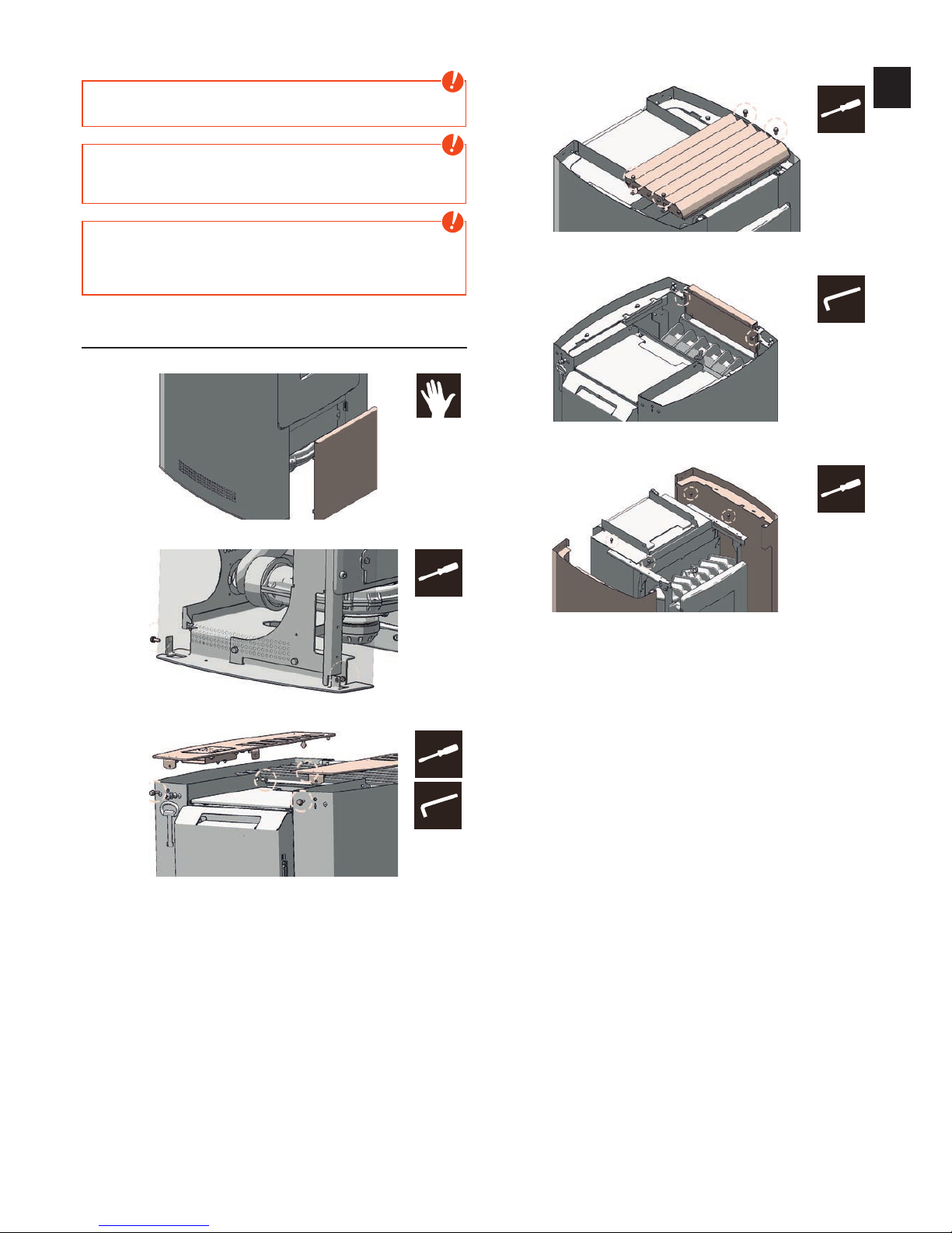
Open the lower front panel by simply lifting. The front panel is simply hooked
Open the 2 lower hex screws used to secure the side panel
Open the 2 hex screws and the 2 Allen screws used to attach the two covers.
Lift the covers. Make sure that you disconnect the control unit!
Open the 4 vertical hexagonal screws used to attach the convection fins and lift
the convection fins up and away.
Open the 2 Allen screws used to attach the top panel and lift off the cover
upwards.
Finally, you can loosen the 4 hex screws that are used to fasten the left and
right side panels open, and remove the side panels.
Install the removed parts in reverse order.
#8
#8
#8
3
#8
3
Page 14
7. INTERNAL CONTROLS
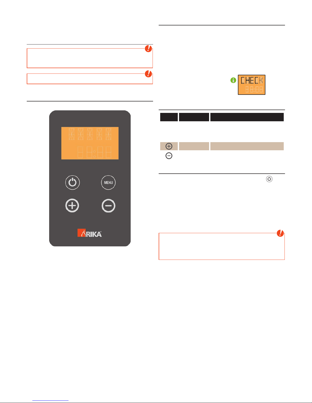
The stove has a modern programmable microprocessor control. The individual
unit functions can be preset by the user via the internal controls located in the
right casing (keyboard with operating display).
Basics
Note
Manipulation of hardware components may only be performed by trained
specialist dealers and service. Incorrect handling of these parts leads to
loss of warranty and guarantee claims!
Note
The unit may only be put into operation when assembled completely!
Operation
All settings and functions can be controlled via this unit.
The display is illuminated when touched. After some seconds the display lighting
turns off again.
EASY MODE - simple heating operation
Your stove is in simple heating mode EASY OFF when delivered in order to ease
your start in the world of RIKA pellet stoves. The heat output of the stove can
only be increased or reduced in 5 % increments in this mode. As soon as the
stove is connected to the socket, the standard display EASY OFF appears.
The message „CHECK“ appears in the display as soon as your pellet stove is
connected to the power supply (even after a power failure). The display buttons
are disabled for approx. 10 seconds as the stove conducts an initialisation of
all components. When „CHECK“ disappears from the display the stove can be
started up.
"CHECK" appears in the display whenever
the stove ist re-supplied with power.
CHECK
EASY OFF - inactive state
key display description
EASY OFF
Standard display for stove switched off in
simple heating mode.The output can also be
regulated between 30% and 100% with the
stove switched off (EASY 30 – EASY 100).
EASY 45 Pressing increases output by 5%
EASY 35 Pressing decreases output by 5%
Start - scavenge - tip - ignition
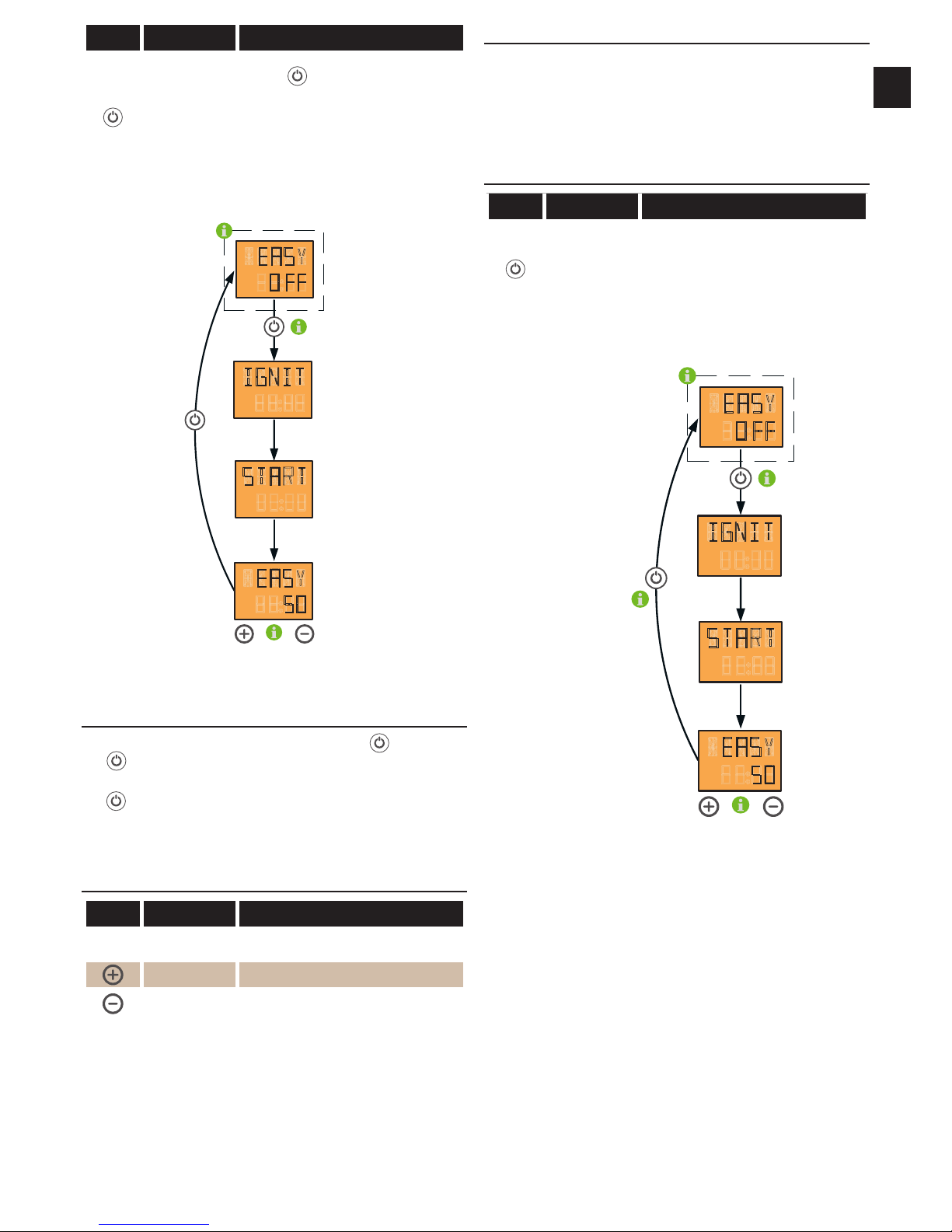
The pellet stove is started in the scavenging phase by pressing the button.
The scavenging phase lasts approx. 50 seconds and is used to eliminate any
adverse draft conditions in a cold flue. The grate tips automatically during the
scavenging process and any ash leftover from the previous combustion phase
falls into the ash tray.
Depending on the fill level of the screw conveyor the ignition process can take
approx. 5 to 30 minutes until the first flame is visible.
If the first ignition attempt is unsuccessful, further ignition attempts will be
initiated automatically. This may occur if the screw conveyor is not completely
full during the ignition process (e.g. first start after refilling empty container).
Note
In the event of a false start remove any unburnt pellets and ash from the
combustion cavity. Never replace unburned pellets from the fire pot in the
supply container.
FIRE HAZARD DUE TO RESIDUAL EMBERS
Page 15
|
15
EN
14
key display description
EASY OFF
IGNIT
START
EASY 35
Pressing
starts the unit.
This is shown by IGNITE in the display; this is
replaced by START after a brief time.
EASY xx appears in the display after the
start phase (xx stands for a value between
30% and 100%, depending on output)
to c hang e the power setting
press „ + “ or „ -“ k eay ( the setting will b e c hang ed in 5 % steps
sing le press
EASY
EASY
O FF
IGNIT
START
50
Stopping during ignit or startphase
If switching off occurs again 50 sec. within switching on ( -key) (at least 2
sec.
-key), the pellet stove returns to inactive status.
If switching off occurs during the ignition process (IGNIT or START) (at least 2
sec.
-key), IGNIT OFF or START OFF appears in the display and the burn-out
phase is initiated. The pellet support stops - the flue gas fan continues to burn
any pellet residues (approximately 10 minutes). The stove changes to EASY
OFF.
EASY 40 – operation
key display description
EASY 40
Standard display for stove switched on in
simple heating mode. (40 is the output in %)
EASY 45 Pressing increases output by 5%
EASY 40 Pressing decreases output by 5%
Cleaning and tipping during operation
The automatic cleaning process is conducted every hour for approx. 2 minutes.
During this phase the air vents that are necessary for combustion are blown
clean.
The pellet stove enters the burnout phase every 7 hours. A tipping process is
conducted automatically. The start-up phase is automatically re-initiated after
completion of the burnout phase and operation continues
EASY 40 – switch off
key display description
STOP
EASY OFF
The burnout phase is initiated by pressing for
at least 2 seconds (until the change is visible
on the display). The pellet support stops the flue gas fan continues to burn any pellet
residues (approximately 10 minutes).
The stove changes to EASY OFF.
c hang e power setting b y
pressing the „ + “ or „ -“ k ey
( c hang e in 5 % inc rem ents)
sing le press
pressing the b utton
( until the c hang e is visib le
on the display)
EASY
EASY
O FF
IGNIT
START
50
Page 16
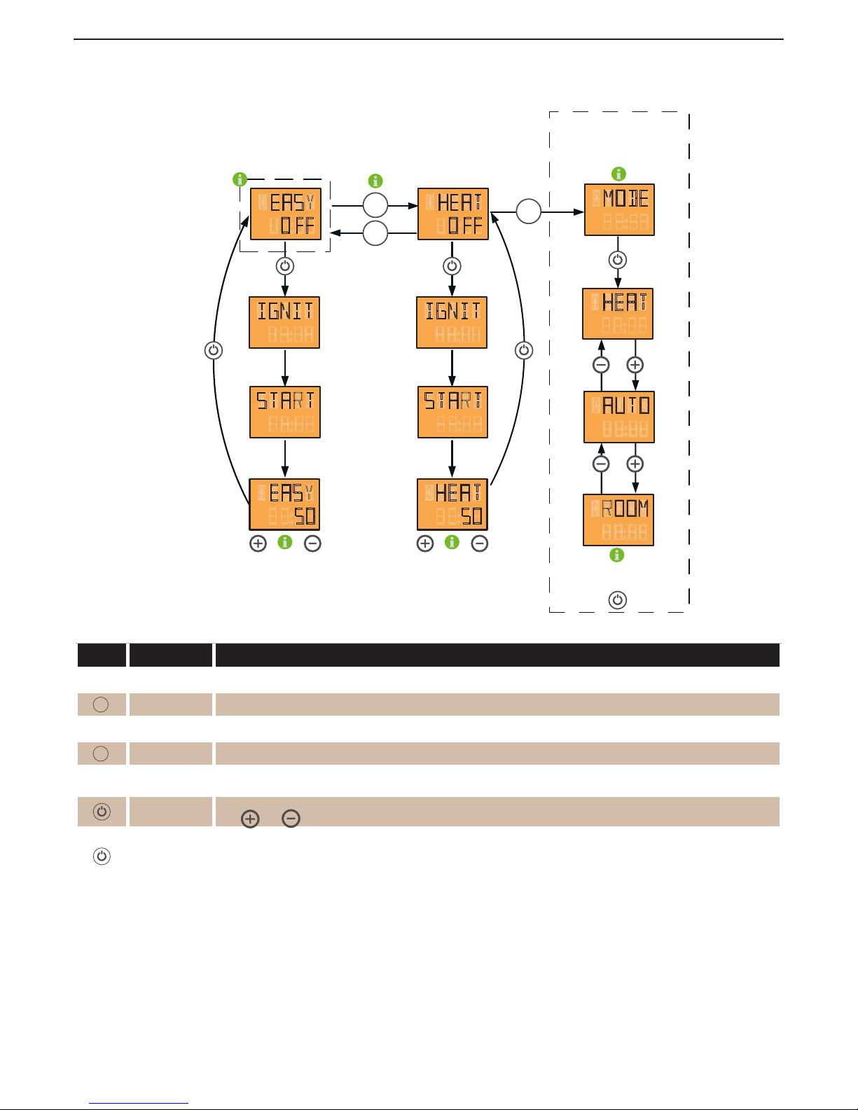
Extended heating operation - HEAT MODE - comfort funktions
In addition to the basic functions of simple heating operation, the RIKA pellet stove provides extra comfort functions. However, before you can use the comfort
functions such as frost protection, installation of an external room thermostat, regulation of the stove mobile telephone, child safety device, you have to change
from simple hating to comfort mode.
c o m f o r t f u n c t i o n s
display panel
display of
respec tive operating status
S witc h b etween EA S Y and HEA T m odes
press m enu k ey f or at least 5 sec onds
selec tion of c om f ort f unc tion
req uired HEA T / A U T O / R O O M
b y pressing the I / O k ey
MENU
MENU
HEAT
ROOM
EASY
5050
MENU
c hang e heat output b y
pressing the „ + “ or „ -“ k ey
( c hang e in 5 % inc rem ents)
c hang e heat output b y
pressing the „ + “ or „ -“ k ey
( c hang e in 5 % inc rem ents)
m enu item m ode only ac tive
in c onnec tion with the R I KA room sensor
or the R I KA wireless room sensor
HEAT
O FF
EASY
O FF
IGNIT
START
MODE
HEAT
AUTO
IGNIT
START
key display description
EASY OFF Standard display for stove switched off in simple heating mode.
MENU
Pressing for at least 5 seconds changes to HEAT mode. The change is also shown in the display as confirmation.
HEAT OFF Standard display for stove switched off in extended heating mode. (comfort functions can now be selected)
MENU
Pressing once changes to display MODE
MODE
You can select one of three possible stove comfort functions. (the menu item Mode is only active in connection with the RIKA
room sensor or the RIKA wireless room sensor active).
Pressing once takes you to the comfort function selection and you can change between the individual comfort functions using
keys
and .
HEAT
AUTO
ROOM
Pressing again confirms the comfort function currently visible HEAT, AUTO or ROOM.
Page 17
|
17
EN
16
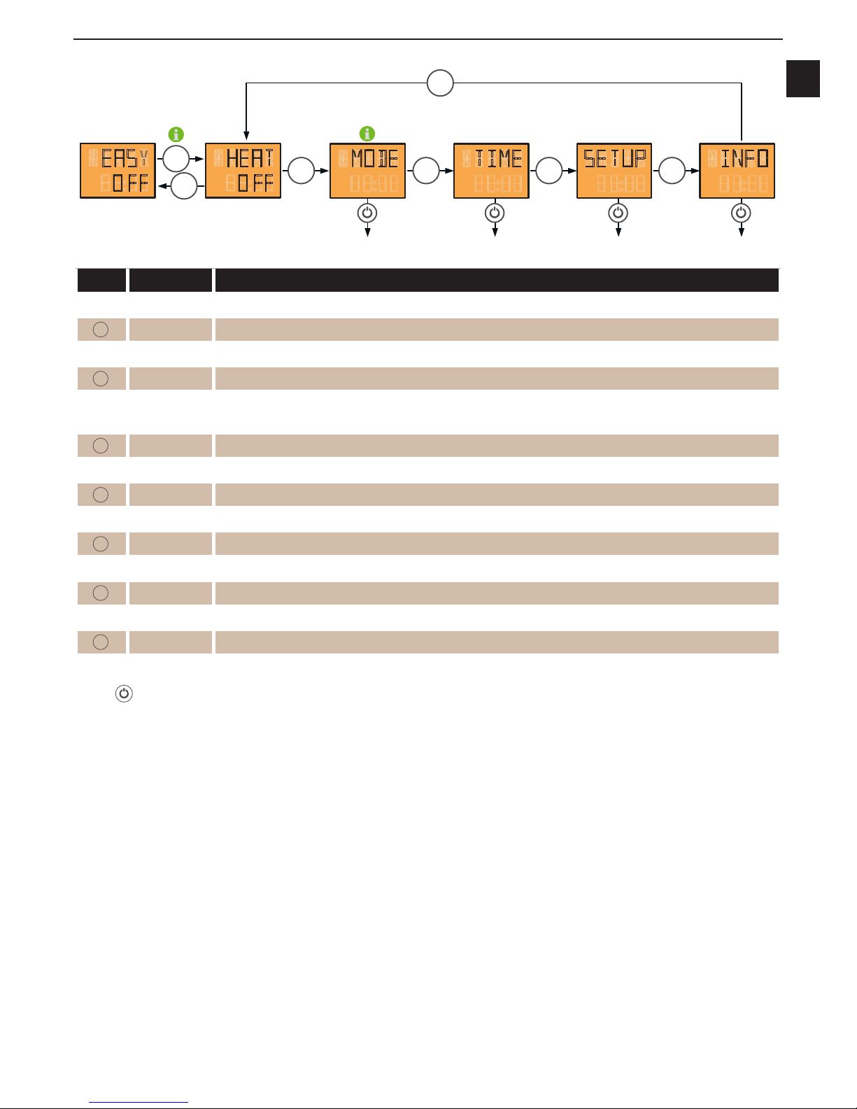
Menu structure and main menu level
switc h b etween EA S Y and HEA T m odes
press m enu k ey f or at least 5 sec onds
m enu item m ode only ac tive in
c onnec tion with the R I KA room sensor or the R I KA wireless room sensor
EASY
O FF
MODE TIME SETUP INFO
HEAT
O FF
MENU
MENU MENU MENU MENU
MENU
MENU
key display description
EASY OFF Standard display for stove switched off in simple heating mode.
MENU
Pressing for at least 5 seconds changes to HEAT mode. The change is also shown in the display as confirmation.
HEAT OFF Standard display for stove switched off in extended heating mode.
MENU
Pressing once changes to display MODE
MODE
You can select one of three possible stove comfort functions. (The menu item Mode is only active in connection with the GSM
option, the RIKA room sensor and/or the RIKA wireless room sensor active, also see “Extended heating operation – comfort
functions”).
MENU
Pressing once changes to display TIME
TIME Setting regarding the time are made here. (Heating time is only available with RIKA room sensor or RIKA wireless room sensor).
MENU
Pressing once changes to display SETUP
SETUP All the additional functions can be regulated here.
MENU
Pressing once changes to display INFO
INFO Access to information menu, various system parameters, temperatures and operating information can be called up here.
MENU
Pressing once changes to display HEAT OFF
HEAT OFF Standard display for stove switched off in extended heating mode.
MENU
Pressing for at least 5 seconds changes to EASY mode. The change is also shown in the display as confirmation.
EASY OFF Standard display for stove switched off in simple heating mode.
Pressing
once on the respective main menu items MODE, TIME, SETUP and INFO selects the submenu items.
The individual main menu items TIME, SETUP and INFO are explained in more detail on the next pages.
The menu navigation described above remains the same during operation. The respective heat output set is shown in the display instead of EASY OFF or HEAT
OFF. For example EASY 30 or HEAT 30
Page 18
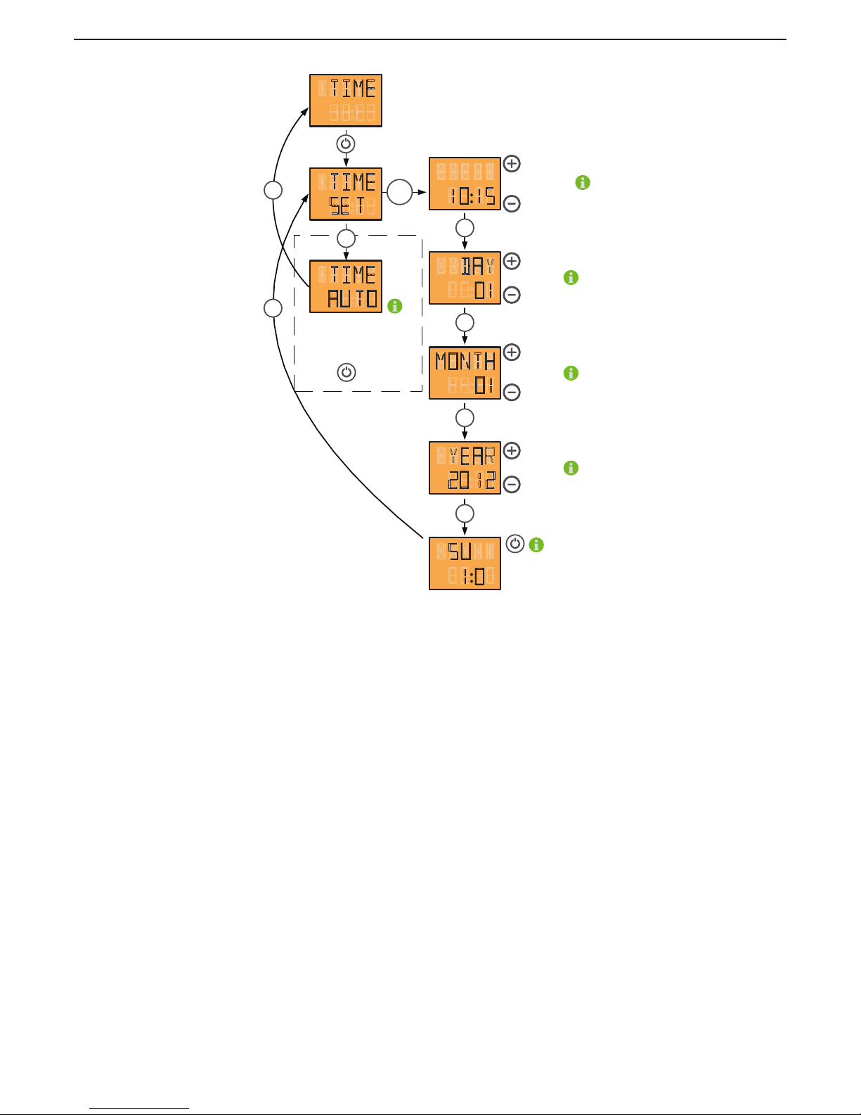
Main menu time - time adjustment
the T I M E A U T O display b ox is only
visib le in c onnec tion with the R I KA room -
and/ or the R I KA wireless room sensor.
P ressing the I / o k ey tak es you to the
sub m enu of the heating tim e prog ram m ing
S et hours and m inutes
using the „ + “ and „ -“ k ey
S et day using the
„ + “ and „ -“ k ey
S et m onth using the
„ + “ and „ -“ k ey
S et year using the
„ + “ and „ -“ k ey
h e a t i n g
t i m e
W ith I / 0 , the date is rec orded.
T he tim e is stored onc e set.
TIME
TIME
DAY
MONTH
YEAR
SU
TIME
AU TO
10 15
01
01
1220
1 0
SE T
MENU
MENU
MENU
MENU
MENU
MENU
MENU
MENU
Page 19
|
19
EN
18
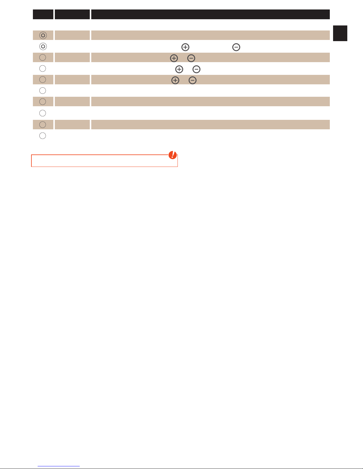
key display description
TIME Display to enter the control level for time adjustment.
TIME SET All the settings concerning time, date and heating time (optional) are made here.
00:00
Setting the time. Hour display is changed using
, minute display using .
MENU
DAY 01
Setting the day. Display is changed using
and .
MENU
MONTH 01
Setting the month. Display is changed using
and .
MENU
YEAR 2012
Setting the year. Display is changed using
and .
MENU
SU 1:0 The actual day is shown in the display as confirmation.
MENU
TIME SET Back to TIME SET.
MENU
(TIME AUTO)
(Setting the heating times. The menu item TIME AUTO only appears in connection with the RIKA room sensor and the RIKA
wireless room sensor). (Please see the operating instruction enclosed for the option for setting the heating times).
MENU
TIME Back to TIME.
MENU
Repeated pressing returns you to the main menu level.
Note
Summer- and wintertime is not changed automatically
Page 20
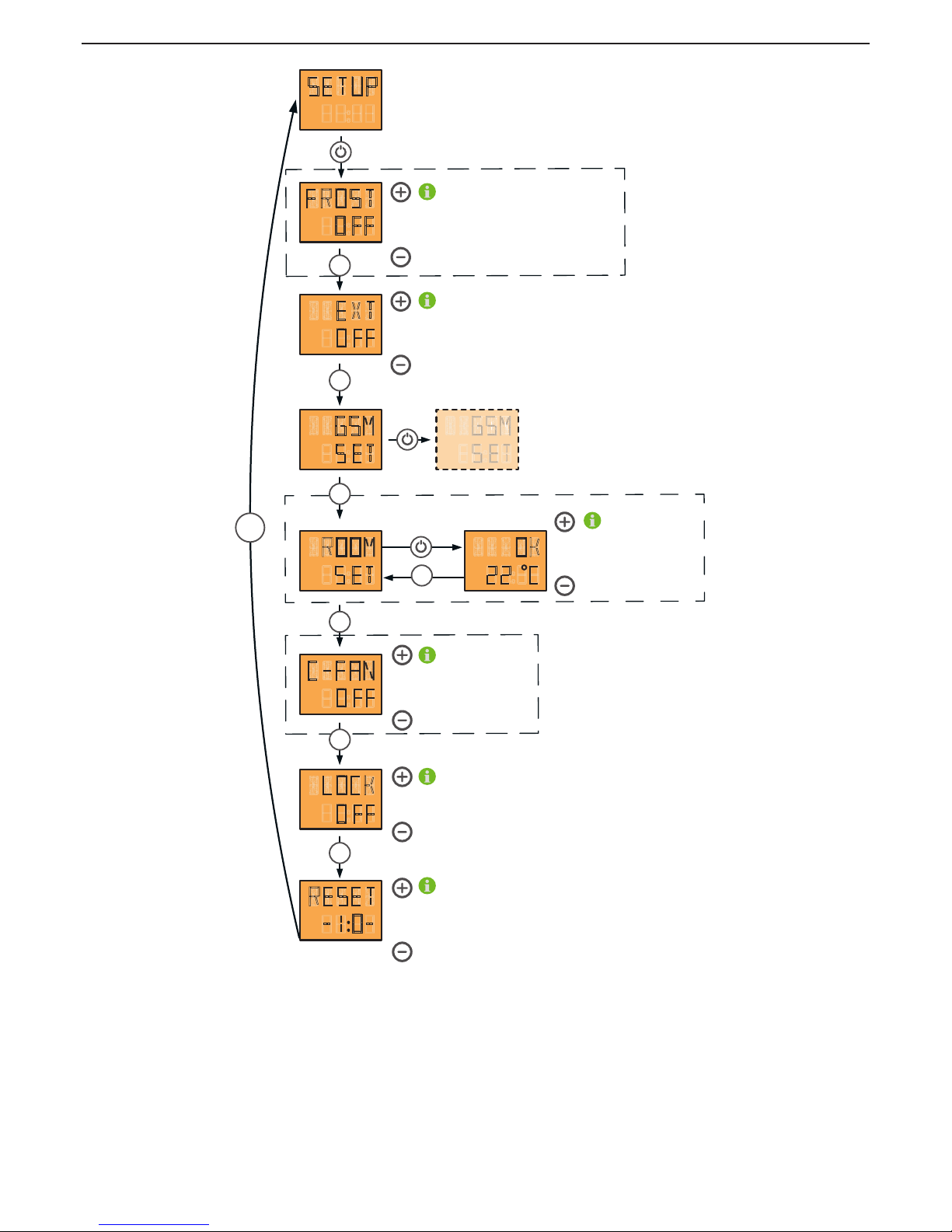
Main menu setup - additional functions
FROST
GSM
S ET
ROOM
S ET
OK
22 C
SETUP
O FF
EXT
O FF
C-FAN
O FF
LOCK
O FF
RESET
-1 0-
the f rost protec tion is ac tivated or deac tivated b y
using the „ + “ and „ -“ k ey. T he f rost protec tion f unc tion
is only ac tive in c onnec tion with a
room therm ostat.
.
T he loc k f unc tion is
switc hed O N or O F F
b y using the „ + “ or „ -“ k ey
A ll the param eters set
are reset to f ac tory values
b y using the I / O k ey
T he C-F an f unc tion is
switc hed O N or O F F
b y using the
„ + “ or „ -“ k ey
C O MO
T O P O
P I C O
R EV O
the deviation in the ac tual tem perature
of the room sensor is c hang ed using
„ + “ and „ -“
( adj ustm ent rang e is + / - 4 ° C) .
d i s p l a y m e n u i t e m F R O S T
o n l y i f t h e r o o m s e n s o r i s c o n n e c t e d .
d i s p l a y m e n u i t e m R O O M S ET
o n l y i f t h e r o o m s e n s o r i s c o n n e c t e d
MENU
MENU
MENU
MENU
MENU
MENU
MENU
MENU
the ex ternal req uest is ac tivated or deac tivated b y
using the „ + “ and „ -“ k ey. T he ex ternal req uest f unc tion
is only ac tive in c onnec tion with a
room therm ostat.
Page 21
|
21
EN
20
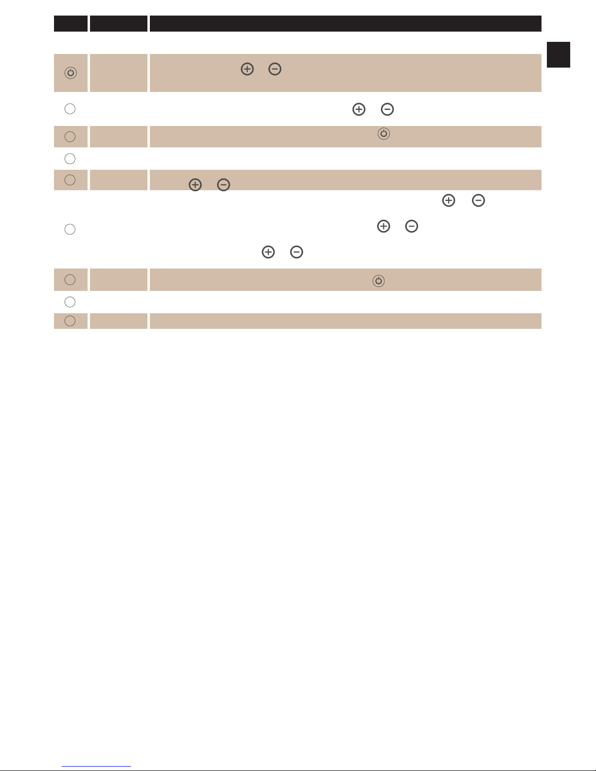
key display description
SETUP
Display to enter the control level for additional functions. You can change between the operating status On (active) and OFF
(inactive).
FROST OFF
Display of operating status of additional function FROST, frost protection (only in connection with RIKA room sensor and RIKA
wireless room sensor). Using
and you can switch between FROST OFF (inactive) and FROST ON (active). Frost protecion
is only active in combination with the comfortfunctions HEAT OFF, ROOM OFF and AUTO OFF. Starting temperature 8°C, stopping
temperature 13°C
MENU
EXT OFF
Display of operating status of additional function EXT external unit such as e.g. a customary room thermostat (see Comfort
function – external room thermostat for more information). Using
and you can switch between EXT OFF (inactive) and
EXT ON (active)..
MENU
GSM SET
All settings concerning Telephone option – GSM are made here. Pressing
takes you to the submenu of Telephone option –
GSM. Please see the operating instructions accompanying the Telephone option – GSM for settings.
MENU
ROOM SET
The room temperature displayed may deviate from the actual temperature and therefore the sensor may be calibrated by +/4°C. Thus the actual temperature of the room sensor can be adjusted e.g. to the house thermometer.
MENU
C-FAN OFF
Display of the operating status of the optional cross-flow fan. You can switch between C-FAN OFF (inactive) and C-FAN ON (active)
by pressing
and .
MENU
LOCK OFF
Display of operating status of additional function LOCK child safety device (key lock). Using
and you can switch
between LOCK OFF (inactive) and LOCK ON (active).
To lock the keyboard with active child protection device (LOCK ON), press
and at the same time for at least 5 seconds
in the standard mode EASY or HEAT. LOCK appears in the display as confirmation.
To unlock the keyboard again press
and at the same time for at least 5 seconds. LOCK OFF appears in the display as
confirmation.
MENU
RESET
- 1:0 -
Any settings changed can be reset to the delivery status here. Pressing
resets the stove to the factory settings.
MENU
SETUP
Display to enter the control level for additional functions. You can change between the operating status On (active) and OFF
(inactive).
MENU
Repeated pressing returns you to the main menu level.
Page 22
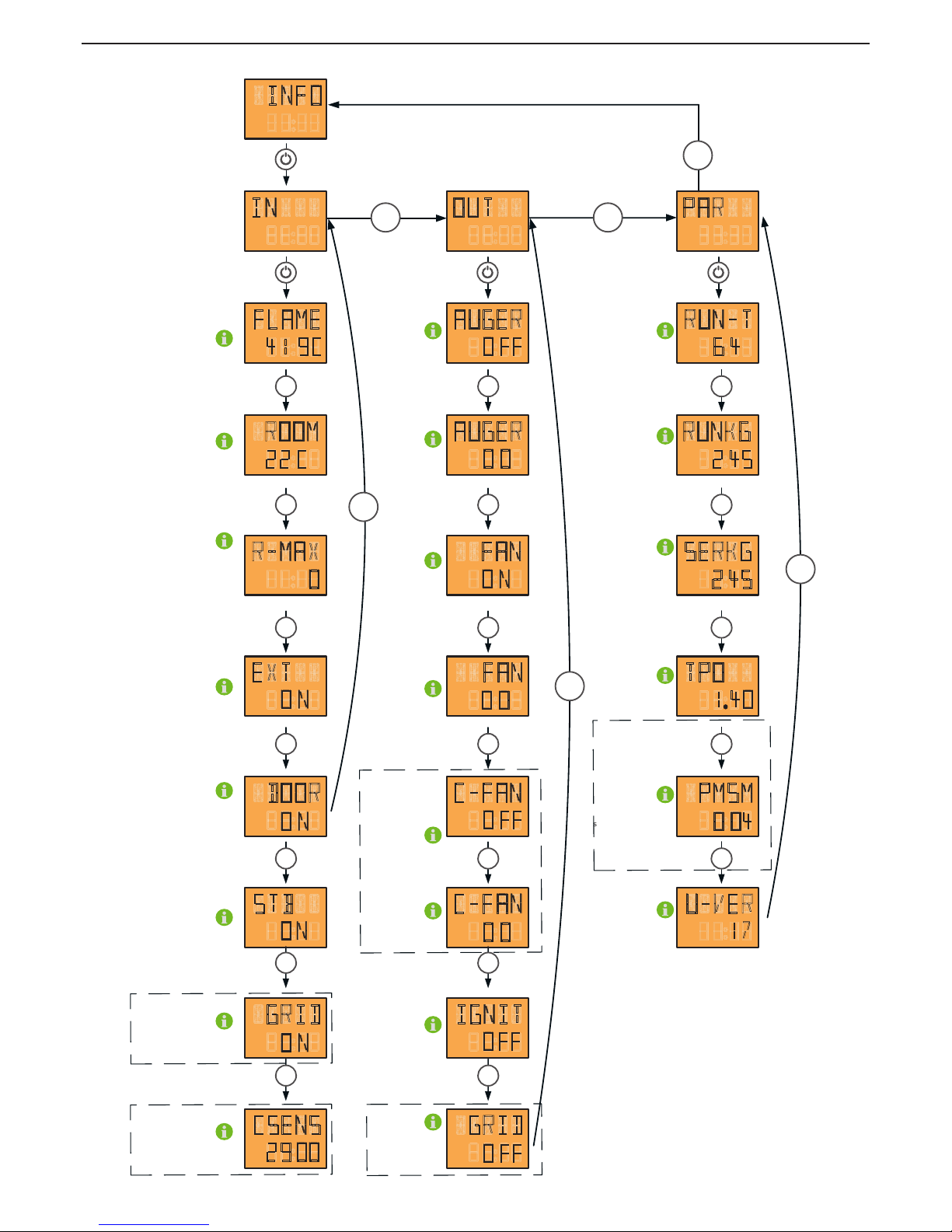
Main menu info - additional information
c u r r e n t f l a m e t e m p e r a t u r e
c u r r e n t r o o m t e m p e r a t u r
TOPO
TOPO
COMO
TOPO
PICO
REVO
if active
MENU
MENU
MENU
MENU
MENU
MENU
MENU
MENU
MENU
MENU
MENU
MENU
MENU
MENU
MENU
MENU
MENU
MENU
MENU
MENU
MENU MENU
MENU
MENU
MENU
m a x i m u m d u r a t i o n w i t h o u t
c o n n e c t i o n t o w i r e le s s
r o o m s e n s o r . V a l u e c a n b e
r e s e t u s in g I / O k e y
c u r r e n t o p e r a t i n g s t a t u s
o f e x t e r n a l r e q u e s t
c o m b u s t i o n c h a m b e r d o o r
o p e n / c l o s e d o r d o o r
c o n t a c t s w i t c h o n / o f f
s a f e t y t e m p e r a t u r e l i m i t e r
c o n t a c t o p e n / c lo s e d
t i p g r a t e c o n t a c t
o p e n / c l o s e d
d is p l a y o f c u r r e n t
C -s e n s o r v a l u e
t i p g r a t e m o t o r o n / o f f
i g n i t i o n e l e m e n t o n / o f f
c o n v e c t i o n f a n m o t o r
i n f o r m a t i o n s p e e d
c o n v e c t i o n f a n
m o t o r o n / o f f
i n d u c e d d r a u g h t
b lo w e r m o t o r o n / o f f
i n d u c e d d r a u g h t b l o w e r
m o t o r i n f o r m a t io n s p e e d
s r e w m o t o r i n f o r m a t io n
f e e d a m o u n t
s c r e w m o t o r o n / o f f d is p l a y o f o p e r a t i n g h o u r s
d is p l a y o f t o t a l a m o u n t
c o n v e y e d ( i n k g p e l l e t s )
d is p l a y o f c o n v e y e d p e l l e
a m o u n t s in c e t h e la s t c l e a n i n g
a n d m a in t e n a n c e ( in k g p e l l e t s )
d is p l a y o f c u r r e n t s o f t w a r e
v e r s i o n m a in b o a r d
d is p l a y o f t h e c u r r e n t s o f t w a r e
v e r s i o n o f t h e a u x ili a r y b o a r d
d is p l a y o f c u r r e n t s o f t w a r e
v e r s i o n c o n t r o l p a n e l
IN
ROOM
22 C
R-MAX
0
FLAME
41 9C
EXT
O N
DOOR
O N
STB
O N
GRID
O N
CSENS
29 00
OUT
FAN
O N
FAN
0 0
AUGER
O FF
AUGER
O 0
C-FAN
O FF
C-FAN
O 0
IGNIT
O FF
GRID
O FF
PAR
RUNKG
2 45
SERKG
2 45
RUN-T
6 4
TPO
1 40
PMSM
O 04
U-VER
17
INFO
COMO
TOPO
PICO
REVO
MEMO
Page 23

|
23
EN
22
key display description
INFO Access to information menu, various system statuses, temperatures and operating information can be called up here.
IN INFORMATION INPUTS
FLAME
319
Display of current flame temperature.
MENU
ROOM
22
Display of current room temperature.
MENU
R-MAX Display menu maximum duration without connection to wireless room sensor
MENU
EXTON Display of status of external release. (ON or OFF)
MENU
DOOR ON Display of the status of door contact. (ON or OFF)
MENU
STB ON Display of the status of safety temperature limiter. (ON or OFF)
MENU
GRID ON Status display for the mudhole door contact (ON or OFF)
MENU
CSENS Display of the current C-sensor value
MENU
IN INFORMATION INPUTS
MENU
OUT INFORMATION OUTPUTS
AUGER OFF Display of operating status of screw motor. (ON or OFF)
MENU
AUGER 00 Display of actual push-in rate.
MENU
FAN ON Display of operating status of flue gas blower. (ON or OFF)
MENU
FAN 00 Display of speed of flue gas blower.
MENU
C-FAN OFF Display of the operating status of the optional cross-flow fan. (ON or OFF)
MENU
C-FAN 00 Display of the speed of the cross-flow fan.
MENU
IGNIT OFF Display of operating status of ignition element. (ON or OFF)
MENU
GRID OFF Display of the operating status of the mudhole door motor. (ON or OFF)
MENU
OUT INFORMATION OUTPUTS
MENU
PAR INFORMATION PARAMETER
RUN - T
63
Display of previous total operating hours.
MENU
RUNKG
245
Display of total pellet amount supplied up to present.
MENU
SERKG
245
Display of conveyed pellet amount since the last cleaning and maintenance.
MENU
TPO 0124 Display of current software version loaded on control board. (Scrolling text)
MENU
PMSM-VER 003 Display of the current software version of the auxiliary board. (Scrolling text)
MENU
U-VER 13 Display of current software version loaded on control unit.
MENU
TEL S 12 Coding software
MENU
TEL H 1024 Coding hardware
MENU
PAR Repeated pressing returns you to the main menu level.
Page 24
8. COMFORT OPTIONS
We would point out that auxiliary units may only be connected to the RIKA
interface connection and external connection socket by authorised specialists.
RIKA room sensor/RIKA radio room sensor
This option permits control of your stove via room temperature. You can set
both the room temperature and the heating times required. A room temperature
selected by you is observed during the heating times.
Please see the operating instructions for the option RIKA room sensor and
wireless room sensor for more detailed information.
RIKA phone option – GSM
Your stove can also be controlled via a mobile phone as an additional option.
Please see the operating instructions for the telephone option – GSM for more
detailed information.
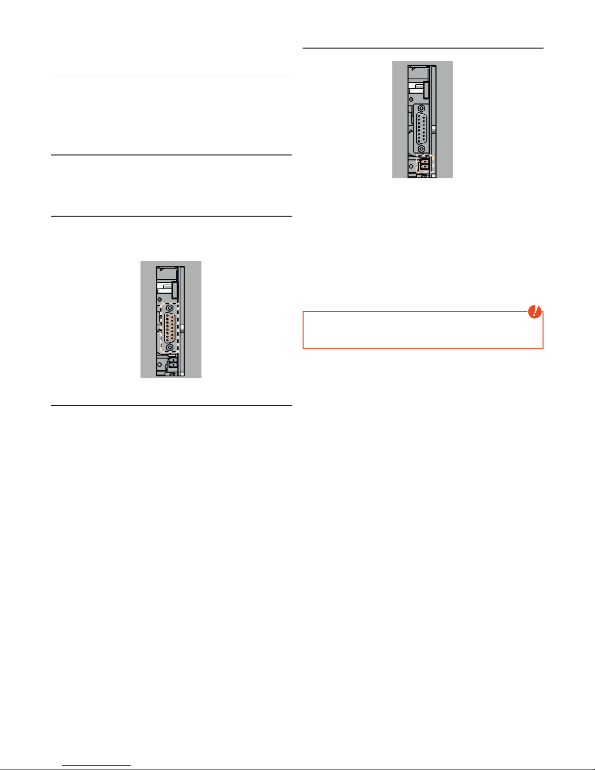
RIKA interface for various options
for various options
The RIKA ROOM SENSOR, the RIKA WIRELESS ROOM SENSOR and the RIKA
PHONE OPTION – GSM are to be connected to the interface (stove rear) using
the connection cable supplied.
External room thermostat
Your stove has an interface on the rear wall to which you can connect a
customary room thermostat. This requires a 2-pole cable of 0.5 – 0.75 mm²
cross-section that you have to connect instead of the cable bridge fitted for
delivery
External connection cable bridge
(condition as delivered)
The stove settings in the menu item Setup are to be checked to ensure the
function of the room thermostat. The external unit must be set to EXT ON
(active) as described above.
This function enables you to deactivate a connected room thermostat (setting
EXT OFF).
All further settings required to your thermostat can be taken from the room
thermostat operating instructions.
The connected room thermostat must be operated in the HEAT menu. You can
select the heat output you wish for the room temperature selected.
If an external demand for stopping the pellet stove occurs, it takes about 5
minutes until the pellet stove switches to burn out phase.
Note
Operation is not possible unless either a cable bridge or an external room
thermostat is connected. The external demand has priority over all operating
modes (EASY/HEAT/AUTOMATIC/ROOM).
Page 25

|
25
EN
24
9. MODES
Note
When operated correctly, your stove can not overheat. Improper operation
may shorten the life expectancy of electrical components (blowers, motors
and electric control) and is not allowed!
Pellet operation Heat/Easy/Automatic/Room
HEAT/EASY
The pellet burner start and stop as well as the setting of the required heat
output are executed directly in the HOME – main menu.
AUTOMATIC MODE
The change between standby operation and neutral as well as the setting of the
required heat output are executed via the display in the HOME – main menu.
The pellet burner starts in standby mode within the heating times when the
actual room temperature is below the set room temperature, or outside of
the heating times when the actual room temperature is below the set room
temperature.
When achieving the set room temperature, the pellet burner stops.
Stove start is not possible in neutral status (OFF), the system is switched off.
ROOM MODE
The change between standby operation and neutral as well as the setting of the
required heat output are executed via the display in the HOME – main menu.
The pellet burner starts in standby mode if the actual room temperature is
below the set room temperature.
When achieving the set room temperature, the pellet burner stops.
Stove start is not possible in neutral status (OFF), the system is switched off.
Fuel addition pellet operation
Note
CAUTION when filling! Do not allow the pellet sack to come into contact with
the hot stove. Immediately remove any pellets that have not entered the
supply container!
We recommend maintaining an appropriate level in the supply container to
prevent the fire going out due to lack of fuel. A 15 kg sack of pellets can be
added to the stove once half the pellets in the container have been used up.
Check the level frequently. However the container lid should be kept closed,
except during filling.
When filling the container during operation (opening of the container lid), the
fan is started up and the pellet conveyor is stopped; operation is only resumed
once the container lid is closed (see WARNING AND ERROR MESSAGES)
Pellet container capacity (see TECHNICAL DATA).
Emergency - electrical heating up. without
ignition
Should the units ignition cartridge fail, an emergency operation can be
performed with using fire (ignition cubes). First, start the oven as usual. Wait for
the flushing and the tilting of the grate. Then you open the firebox door and give
a handful of pellets with the ignition cubes in the clean burning trough, ignite it
and then close the firebox door.
Note
Do not use flammable liquids to ignit the stove!
Page 26
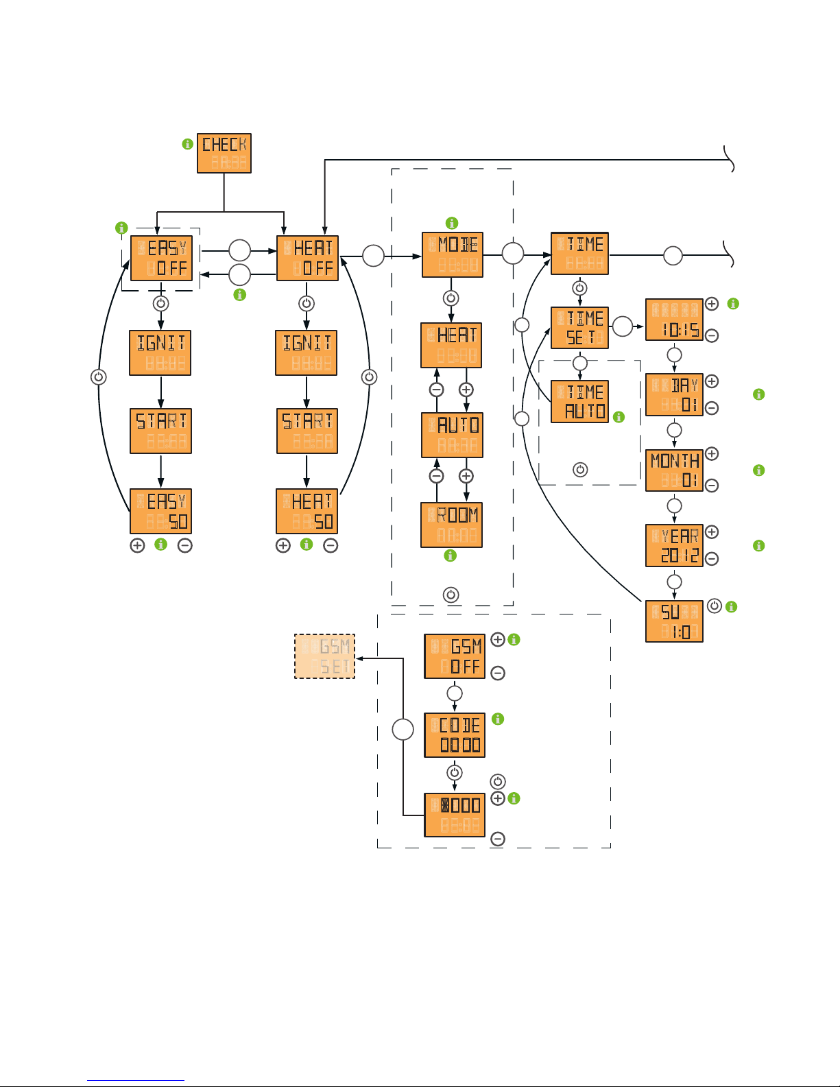
CODE
MENU
the G S M -option is ac tivated
or deac tivated using the „ + “ and „ -“ k ey
display of c ode c urrently set
the respec tive ac tive num b er is c hang ed
using the „ + “ and „ -“ k ey. T he num b er is
c onf irm ed and the nex t position is c hang ed to
b y pressing the I / O k ey.
MENU
GSM
O FF
OO OO
G S M- o p t i o n
the T I M E A U T O display b ox is only
visib le in c onnec tion with the R I KA room -
and/ or the R I KA wireless room sensor.
P ressing the I / o k ey tak es you to the
sub m enu of the heating tim e prog ram m ing
S et hours and m inutes
using the „ + “ and „ -“ k ey
S et day using the
„ + “ and „ -“ k ey
S et m onth using the
„ + “ and „ -“ k ey
S et year using the
„ + “ and „ -“ k ey
h e a t i n g
t i m e
W ith I / 0 , the date is
rec orded. T he tim e is
stored onc e set.
TIME
TIME
DAY
MONTH
YEAR
SU
TIME
AU TO
10 15
01
01
1220
1 0
SE T
MENU
MENU
MENU
MENU
MENU
MENU
MENU
MENU
c o m f o r t f u n c t i o n s
display panel
display of
respec tive operating status
S witc h b etween EA S Y and HEA T m odes
press m enu k ey f or at least 5 sec onds
selec tion of c om f ort f unc tion
req uired HEA T / A U T O / R O O M
b y pressing the I / O k ey
MENU
MENU
HEAT
ROOM
EASY
5050
MENU
c hang e heat output b y
pressing the „ + “ or „ -“ k ey
( c hang e in 5 % inc rem ents)
c hang e heat output b y
pressing the „ + “ or „ -“ k ey
( c hang e in 5 % inc rem ents)
m enu item m ode only ac tive
in c onnec tion with the R I KA room sensor
or the R I KA wireless room sensor
HEAT
O FF
EASY
O FF
IGNIT
START
MODE
HEAT
AUTO
IGNIT
START
"CHECK" appears in the display whenever
the stove ist re-supplied with power.
CHECK
MENU
MENU
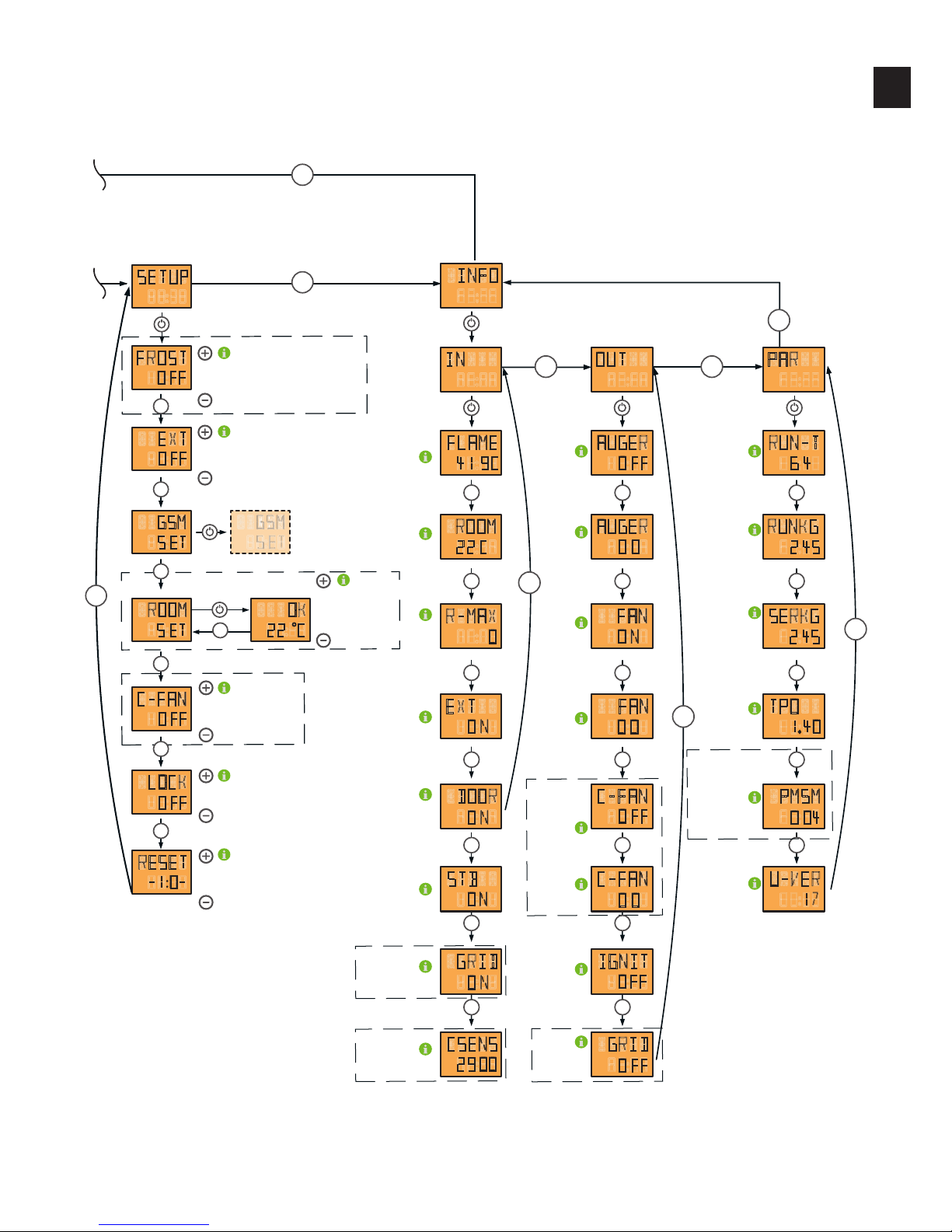
10. MENU OVERVIEW V1.40
Page 27
|
27
EN
26
MENU
MENU
FROST
GSM
S ET
ROOM
S ET
OK
22 C
SETUP
O FF
EXT
O FF
C-FAN
O FF
LOCK
O FF
RESET
-1 0-
t h e f r o s t p r o t e c t i o n i s a c t i v a t e d o r d e a c t i v a t e d b y
u s i n g t h e „ + “ a n d „ -“ k e y . Th e f r o s t p r o t e c t i o n f u n c t i o n
i s o n l y a c t i v e in c o n n e c t i o n w i t h a
r o o m t h e r m o s t a t .
.
Th e l o c k f u n c t i o n i s
s w i t c h e d O N o r O FF
b y u s i n g t h e „ + “ o r „ -“ k e y
A l l t h e p a r a m e t e r s s e t
a r e r e s e t t o f a c t o r y v a l u e s
b y u s i n g t h e I / O k e y
Th e C -Fa n f u n c t i o n i s
s w i t c h e d O N o r O FF
b y u s i n g t h e
„ + “ o r „ -“ k e y
COMO
TOPO
PICO
REVO
t h e d e v i a t i o n i n t h e a c t u a l
t e m p e r a t u r e o f t h e r o o m
s e n s o r i s c h a n g e d u s i n g
„ + “ a n d „ -“
( a d j u s t m e n t r a n g e i s + / - 4 ° C ) .
d is p l ay m en u item F ROS T
o n l y if th e r o o m s en s o r is co n n ected .
d is p l ay m en u item ROOM S ET
o n l y if th e r o o m s en s o r is co n n ected
MENU
MENU
MENU
MENU
MENU
MENU
MENU
MENU
t h e e x t e r n a l r e q u e s t is a c t i v a t e d o r d e a c t iv a t e d b y
u s i n g t h e „ + “ a n d „ -“ k e y . Th e e x t e r n a l r e q u e s t f u n c t i o n
i s o n l y a c t i v e in c o n n e c t i o n w i t h a
r o o m t h e r m o s t a t .
c u r r e n t f la m e t e m p e r a t u r e
c u r r e n t r o o m t e m p e r a t u r
TOPO
TOPO
COMO
TOPO
PICO
REVO
if active
MENU
MENU
MENU
MENU
MENU
MENU
MENU
MENU
MENU
MENU
MENU
MENU
MENU
MENU
MENU
MENU
MENU
MENU
MENU
MENU
MENU MENU
MENU
MENU
MENU
m a x i m u m
d u r a t i o n w i t h o u t
c o n n e c t i o n t o
w i r e le s s r o o m
s e n s o r . V a l u e c a n b e
r e s e t u s i n g I / O k e y
c u r r e n t o p e r a t i n g s t a t u s
o f e x t e r n a l r e q u e s t
c o m b u s t i o n c h a m b e r d o o r
o p e n / c l o s e d o r d o o r
c o n t a c t s w it c h o n / o f f
s a f e t y t e m p e r a t u r e l i m i t e r
c o n t a c t o p e n / c l o s e d
t i p g r a t e c o n t a c t
o p e n / c l o s e d
d i s p la y o f c u r r e n t
C -s e n s o r v a l u e
t i p g r a t e m o t o r o n / o ff
i g n i t i o n e l e m e n t o n / o f f
c o n v e c t io n f a n m o t o r
i n f o r m a t i o n s p e e d
c o n v e c t io n f a n
m o t o r o n / o f f
i n d u c e d d r a u g h t
b l o w e r m o t o r o n / o f f
i n d u c e d d r a u g h t b l o w e r
m o t o r i n f o r m a t i o n s p e e d
s r e w m o t o r in f o r m a t i o n
f e e d a m o u n t
s c r e w m o t o r o n / o f f d i s p la y o f o p e r a t i n g h o u r s
d i s p la y o f t o t a l a m o u n t
c o n v e y e d ( i n k g p e l l e t s )
d i s p la y o f c o n v e y e d p e l l e
a m o u n t s i n c e t h e la s t c l e a n i n g
a n d m a i n t e n a n c e ( i n k g p e l l e t s )
d i s p la y o f c u r r e n t s o f t w a r e
v e r s i o n m a i n b o a r d
d i s p la y o f t h e c u r r e n t s o f t w a r e
v e r s i o n o f t h e a u x il i a r y b o a r d
d i s p la y o f c u r r e n t s o f t w a r e
v e r s i o n c o n t r o l p a n e l
IN
ROOM
22 C
R-MAX
0
FLAME
41 9C
EXT
O N
DOOR
O N
STB
O N
GRID
O N
CSENS
29 00
OUT
FAN
O N
FAN
0 0
AUGER
O FF
AUGER
O 0
C-FAN
O FF
C-FAN
O 0
IGNIT
O FF
GRID
O FF
PAR
RUNKG
2 45
SERKG
2 45
RUN-T
6 4
TPO
1 40
PMSM
O 04
U-VER
17
INFO
COMO
TOPO
PICO
REVO
MEMO
Page 28

11. WARNINGS AND ERROR MESSAGES
If a malfunction occurs, the main menu is switched to and the malfunction is displayed in marquee. The malfunction is acknowledged by pressing for at least
2 seconds.
The button must be depressed until the change in the operating status appears on the display.
Note
If error messages recur directly, customer service is to be notified immediately. In the case of error messages that pose a safety risk, burnback and flue gas
flap is activated and the stove is automatically switched off
Display Malfunction designation Cause / remedy
STB >I/O<
Safety temperature limiter is activated Establish cause of activation; eliminate this and reset using reset button
directly at STB. The error message must then also be acknowledged.
Only with cooled stove.
NO PELLETS >I/O<
No pellets in container May also occur on first start (first filling). Check whether there are
sufficient pellets in the container and re-start unit after acknowledging
malfunction.
- Screw conveyor blocked
- Flame sensor sleeve dirty
- Chimney draught too great
FAN DEFECT >I/O<
Flue gas blower defective Acknowledge the error message.
FLAME SENSOR
DEFECT >I/O<
Flame sensor defective Acknowledge the error message.
ROOM SENSOR SIGNAL LOST
>I/O<
Rika room sensor reception defective Transmission between the transmitter and receiver has been lost.
If the error message appears again immediately after re-starting the
device, it means either the battery is flat or the component is defective.
SERVICE >I/O<
Pellet amount for cleaning and maintenance
exceeded
Acknowledge the message and perform cleaning or maintenance
procedures (see CLEANING AND MAINTENANCE) durchführen.
CALL SERVICE MOTOR
Pellet backlog Overfilling of the combustion cavity with a subsequent backlog of
pellets in the drop chute has been detected.
The error message can be acknowledged by pressing the
MENU
and
button simultaneously (held until the error message disappears).
DOOR OPEN >I/O<
Door open Check to make sure the door is closed and that the door contact
switch engages.
(The DOOR OPEN message doesn‘t need to be acknowledged; the
display will disappear when the door is closed.)
AUGER-PMSM
DEFECT >I/O<
Screw motor defective Acknowledge the error message.
Page 29
|
29
EN
28
12. CLEANING AND MAINTENANCE
Basic information
Note
Your stove must be switched off and cooled before any maintenance work is
performed. Ensure that you do not vacuum into the combustion air line during
heating operation during any cleaning (vacuuming). You could vacuum out
embers – FIRE RISK!
Note
SERVICE appears in the display after consumption of 700 kg pellets. Cleaning
and maintenance is to be performed.
This message can be acknowledged by pressing ENTER and operation can
be continued. The number of SERVICE messages is stored in the background.
Note
Only work on the unit when the mains plug has been disconnected.
The frequency with which the stove requires cleaning and the maintenance
intervals depend on the fuel you use. High moisture content, ash, dust and chips
may more than double the maintenance required. We would like to again point
out that only tested and recommended pellets or logs may be used as fuel.
Tip
wood as fertiliser - The mineral content of the wood remains in the combustion
chamber as ash as a residue of the combustion. This is an excellent fertiliser
for all plants in the garden; it is a completely natural product. The ash should
be stored first and extinguished with water.
Note
Ash may contain embers – only place ash in sheet steel containers.
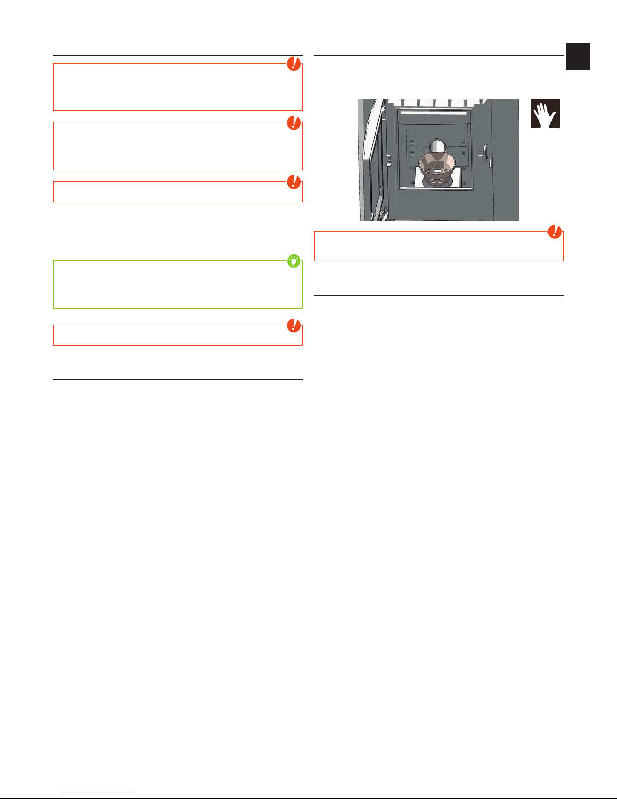
Open the combustion chamber door
To open or close the combustion chamber door use the included key. This key
can also be stored on the back of the stove.
Cleaning the fire trough
Despite the automatic ash dumping prior to and during heating operation,
care should be taken that the air intake openings are not blocked with ash or
clinker. Remove the clinker using the wire brush supplied and vacuum out the
fire trough.
Note
Clean the fire trough regularly. Only clean when cold, when embers are
extinguished!
Ampty the ash drawer
Empty the ash drawer regularly. The ash drawer is simply pulled forward with
the combustion chamber door open
Page 30
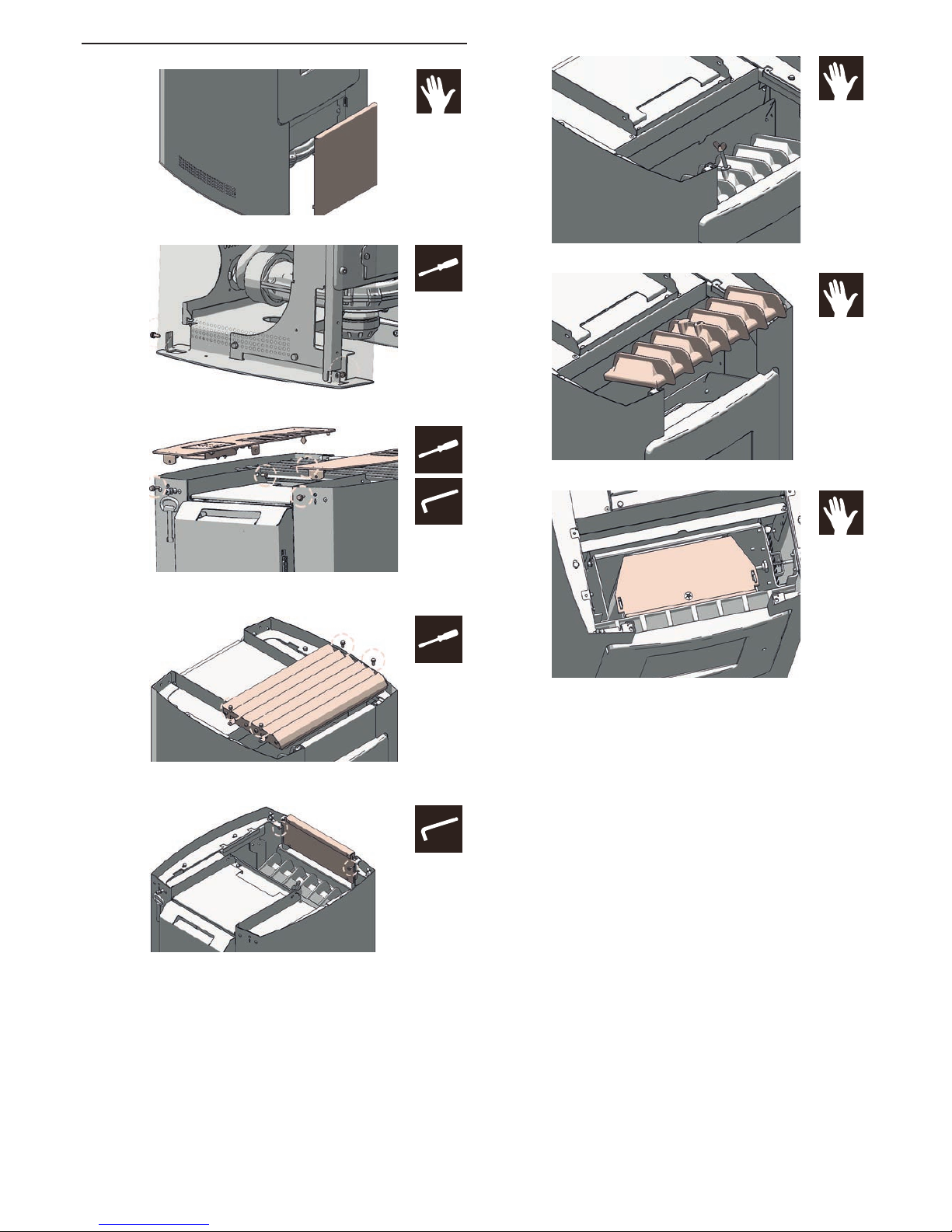
Cleaning flue pipes
Open the lower front panel by simply lifting. The front panel is simply hooked.
Open the 2 lower hex screws used to secure the side panel.
Open the 2 hex screws and the 2 Allen screws used to attach the two covers.
Lift the covers. Make sure that you disconnect the control unit!
Open the 4 vertical hexagonal screws used to attach the convection fins and lift
the convection fins up and away.
Open the 2 Allen screws used to attach the top panel and lift off the cover
upwards.
Open and remove the wing nut, which serves to secure the firebox lid. For ease
of disassembly, hold against the screw through the combustion chamber.
You can now pull the firebox lid upwards.
Now clean the flues on the fire side with the supplied wire brush.
Suck free the exposed interior and the side passages of impurities.
After cleaning, the flue gas passes remove the debris from the flue gas
collection channel!
#8
#8
#8
3
3
Page 31
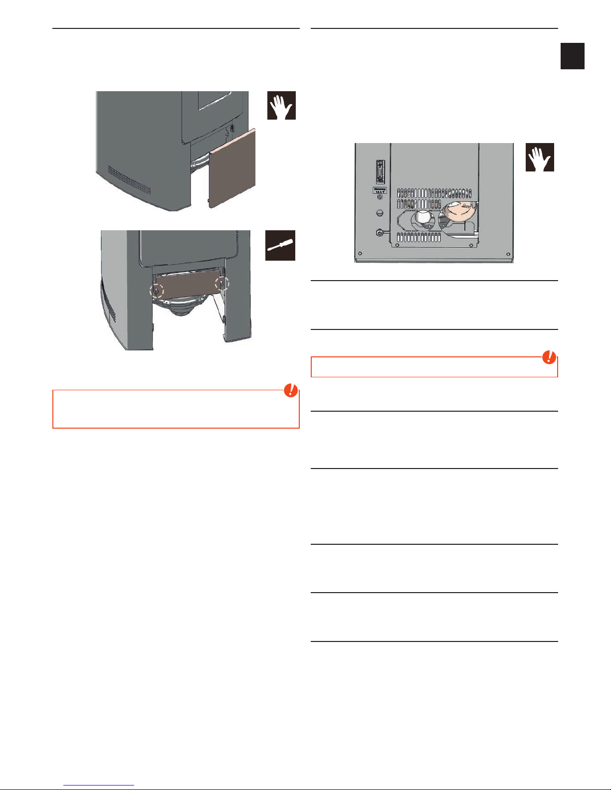
|
31
EN
30
Clean flue gas collecting channel
The flue gas channel should be cleaned twice a year or after approximately
700kg of pellets. The flue gas duct is located in the lower region of the
combustion chamber.
Open the firebox door.
Remove the lower front panel by simply lifting.
Remove the cover plate by opening the hexagon screws.
Suck out the combustion residues from the flue gas collection channel.
Install the removed parts in reverse order.
Note
If the seals of the cleaning cover are not properly sealed, it is possible that
the heater gets “wrong air”, causing incomplete combustion in the grate and
then an accumulation of pellets
Clean flue gas fan housing
The flue gas fan and the flue pipe connection should be cleaned at least 2 times
a year, or after about 700 kg of pellets.
To inspect and clean the flue gas fan, the back wall has to be removed.
The four screws that secure the flue gas fan motor have to be opened and the
motor is carefully to pull out of the case.
Remove with a vacuum cleaner the ash from the fan and flue gas pipes. When
closing again definitely pay attention to leaks.
For cleaning the flue pipe connection, pull the flue pipe from the flue gas fan and
suck out the blower housing.
Cleaning the flame temperature sensor
Remove the dust deposits from the sensor at regular intervals. Use a clean
cleaning cloth or newspaper.
Combustion air - intake
If necessary, please also clean the air intake with a hoover.
Note
Only when the stove is cold! The stove must not be in operation.
Cleaning the pellet container
Do not refill the completely empty container immediately; remove the residues
(dust, chippings etc.) from the empty container. The unit must be disconnected
from the mains!
Cleaning the door glass
The viewing window becomes coated in the case of solid fuels, particularly with
the very fine ash of wood pellets, light or dark depending on the pellet quality
(especially with low output). The glass can be cleaned best with a moist cloth.
Stubborn dirt can be removed with a special cleaner available from your stove
dealer.
Bearings
all built in bearings ( Pellet screw or turning Grid ) should be checked and
cleaned according to the condition or replaced min. once per Year.
Checking door seal
The condition of the seals at doors and glass should be checked at least 1 x per
year. Repair or replace seals depending on condition.
Checking chimneay connection
Inspect and clean connection. Accumulated fly ash may impair the performance
of the stove and pose a safety risk.
#10
Page 32

13. PROBLEMS - POSSIBLE SOLUTIONS
Problem 1
Fire burns with weak, orange flame. Pellets heap up in fire trough, window
sooted up.
Cause(s)
Q Insufficient combustion air
Q Poor chimney draught
Q Stove is sooted over inside
Possible solutions
Q Remove any ash or clinker from the fire trough that may block the air inlets.
If possible swap to better pellet quality (see CLEANING AND MAINTENANCE)
Q Check whether flue gas pipes are blocked with ash (see CLEANING AND
MAINTENANCE).
Q Check whether the suction nozzles and air inlet pipe or flue tube are blocked.
Q Check door and cleaning cover seals for leaks (see CLEANING AND
MAINTENANCE)
Q Clean blower impeller (see CLEANING AND MAINTENANCE)
Q Have service performed by authorised specialist company.
Problem 2
Stove smells strongly and smokes outside.
Cause(s)
Q Burning-in phase (taking into service)
Q Stove has accumulated dust and/or dirt
Possible solutions
Q Wait to end of burning-in phase and vent sufficiently
Q Suction off any dust deposits from the convection air openings at regular
intervals
Problem 3
Flue gas discharge when wood is added and during heating phase.
Cause(s)
Q Inspection openings leak
Q Chimney draught too low
Q Flue pipe connection leaks
Possible solutions
Q Check seals and replace (fire door, plaster cover, ..)
Q Check chimney
Q Check connections and if necessary re-seal
Note
Please note that checks on the control system and wiring ma only be
performed in unit switched dead. Any repairs may only be performed by
trained specialists.
Tip
If a malfunction message occurs, the cause must first be remedied; the
unit can be put back into operation by acknowledging the malfunction at the
internal unit.
Page 33

|
33
EN
32
14. INSTRUCTIONS FOR COMMISSIONING PROTOCOL
FOR PELLET AND COMBI STOVES
The commissioning protocol is to be treated as a documents and serves as
the basis for the warranty and guarantee terms. It is to be completed entirely,
in particular the stove data and addresses, the work to be performed is to be
ticked off after completion. The signatories confirm with their signatures that all
the items on the list have been concluded properly.
Note
Please return 1 completed protocol for putting into service to RIKA Innovative
Ofentechnik GmbH, Müllerviertel 20, A-4563 Micheldorf.
Electrical periphery
It is important that the connection socket in the electrical periphery is earthed.
The operability of any room thermostat present must be checked. The execution
of commands is to be established by phoning in the case of a GSM modem.
Exhaust gas system
The exhaust line, stove and combustion air inlet are part of the combustion
system as a whole; therefore the correct execution must also be checked. The
plug connections should be tight in general since the system works with excess
pressure. The exhaust tube has a diameter of 150 mm which is sufficient for
short distances. In the case of several changes in direction, the resistance
of the exhaust system can increase with the flue to such an extent that the
combustion quality suffers and/or noises arise from the greater flow speed.
Correct determination of the chimney draught can only be performed at nominal
thermal output and serves to evaluate the chimney. If the draught is more than
15 Pa, then a draught limiter should be installed.
Stove functions
These are the basic stove functions that are to be checked and ticked off. The
stove is ready for operation if these functions are ensured.
Operator instruction
This is one of the most important points in the putting into operation. It is very
important that the operator understands the stove properly and is prepared to
assume responsibility for the basic tasks required for operational safety.
In particular the connection between special features of a biomass heating
system and his obligations as well as the warranty and guarantee terms must
be explained. e.g. non-tested pellets and screw blockers, lack of cleaning or
maintenance and stove malfunctions. Thorough instruction can prevent many
complaints.Stove functions
Explanation of the processes in the stove during ignition, normal operation,
cleaning phase etc.
Control
Explain operator’s possibilities to intervene, empty pellet container, room
thermostat, GSM modem, functions and settings, program times if necessary.
Operating instructions: Handover and reference to the content to the following
points, is a document.
Warranty terms
Difference between warranty (statutory) and guarantee (voluntary), terms of
guarantee, determination of wearing parts, reference to pellet quality to be
used and the consequences of poor quality.
Cleaning instructions
Ash and dust occurs with a biomass heating unit. The fire trough is to be
cleaned regularly with regular heating operation (in the case of pellet operation,
the drilled air holes in particular must be free of residues). The ash drawer is
to be emptied regularly. The flue gas pipes are to be cleaned once or twice in
the heating season depending on stove type; by a specialist company is best.
Maintenance
Maintenance work after defined burn-off output is to be performed by specialist
company, including thorough cleaning.
Combustion
All doors must close tightly to prevent intake of false air.
Page 34
Note
Please contact your warranty partner for any warranty questions or claims. This is your dealer or installation company. No warranty claims can be accepted
without proper putting into operation, proper operation according to the operating instructions and the supplements in this information sheet.
Protocol for putting into operation for RIKA pellet and combi stoves date:____________________
Installation address
Name:_________________________________________
Street:_________________________________________
City:___________________________________________
Telephone:______________________________________
Dealer
Name:_________________________________________
Street:_________________________________________
City:___________________________________________
Telephone:______________________________________
Stove data
Stove type: Casing undamaged
Serial number: Operating instructions
Software version: Warranty documents
Touchdisplay version: Door opener
Electrical periphery
Connection socket earthed GSM modem present
Room thermostat present Function checked
Check of system components
Combustion chamber door seal checked Ease of movement burnback flap checked (combi)
Ease of movement flue gas flap checked (combi)
Exhaust line / chimney
Diameter Connection leakproof
Bends Chimney draught
Stove functions
Pellet container filled Grid turns (360°) und keeps in heating position
Tested pellet quality according to Önorm/DIN plus/
ENplus-A1
Ignition element glows
Electrical connections made Screw motors run
Safety flaps tightened (combi) Do pellets fall into the combustion chamber?
Induced draught blower runs Ignition performed
Stove was switched off when handed over
Operator instruction
Stove function Warranty terms
Control Cleaning
Operating instructions Cleaning or maintenance interval
work performed correctly according to order placed
_______________________ _____________________ _______________________
Technican: Operator Client
Company:_______________________________________
Page 35
|
35
EN
34
15. GUARANTEE
These warranty conditions are only valid for the following countries: Austria, Germany and Switzerland. Separate conditions imposed by the importer apply for all
other countries.
For the purpose of timely damage limitation, the warranty claim on the part of the claimant is to be enforced at the RIKA dealer in writing using the invoice and
stating the purchase date, model name, serial number and reason for complaint.
WARRANTY
5 years on the welded stove body. This exclusively applies to defects in materials and workmanship as well as free replacement. Labour and travel times are not
included in the manufacturer’s warranty.
Only original parts supplied by the manufacturer should be used. Loss of warranty on non-observance!
The precondition for the warranty is that the stove has been installed and commissioned properly according to the User and installation manuals valid at the time
of purchase. Connection must be performed by a specialist for such stoves.
Any costs incurred by the manufacturer due to unjustified warranty claims are to be charged to the claimant.
Wear parts and parts affected by fire are excluded, such as glass, coating, surface coatings (e.g. handles, panels), seals, fire trough, grates,
draught plates, deflector plates, combustion chamber liners (e.g. fireclay), ceramics, natural stone, thermo stone, ignition elements, sensors,
combustion chamber sensors and temperature controller.
Damage arising from non-observance of the manufacturer’s instructions for operation of the unit or any damage that is caused by action such as overheating, use
of non-approved fuels, tampering with the device or the flue gas pipe, electrical excess voltage, an incorrect, insufficient or excessive flue draught, condensation,
non-performance or deficient maintenance and cleaning, non-observance of the relevant and applicable building regulations, incorrect operation by the user or
third parties, transport and handling damage is also excluded.
THE WARRANTY DOES NOT AFFECT THE STATUTORY WARRANTY PROVISIONS.
01.07.2013
Page 36

Art.Nr.: Z35486 | 05.03.2014
RIKA Innovative Ofentechnik GmbH
4563 Micheldorf / Austria, Müllerviertel 20
Telefon: +43 7582 686 - 41, Fax-DW: 43
E-Mail: [email protected]
RIKA.AT
Technical and design changes, as well as typesetting and printing errors reserved
© 2014 | RIKA Innovative Ofentechnik GmbH
 Loading...