

Page 1
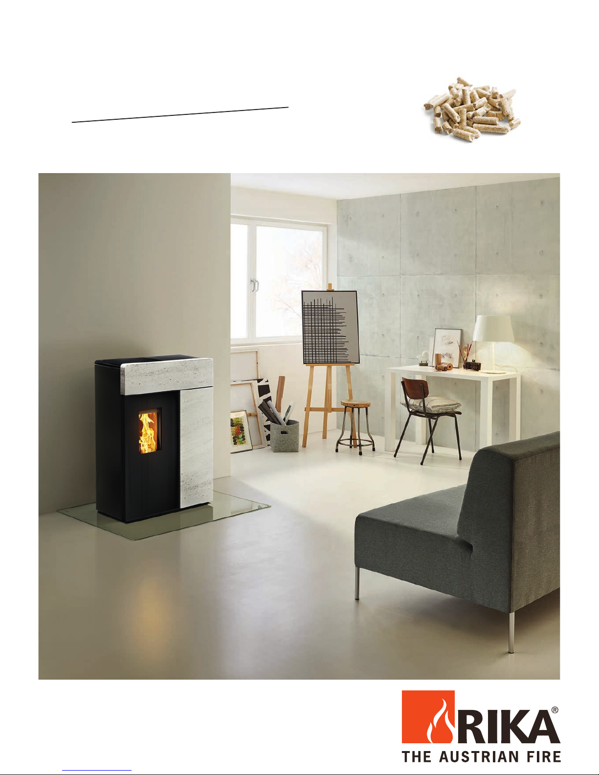
DOMO
Operating Manual
Page 2

TABLE OF CONTENTS
1. PREFACE 3
Explanations to symbols ...........................................................................................................................................................................3
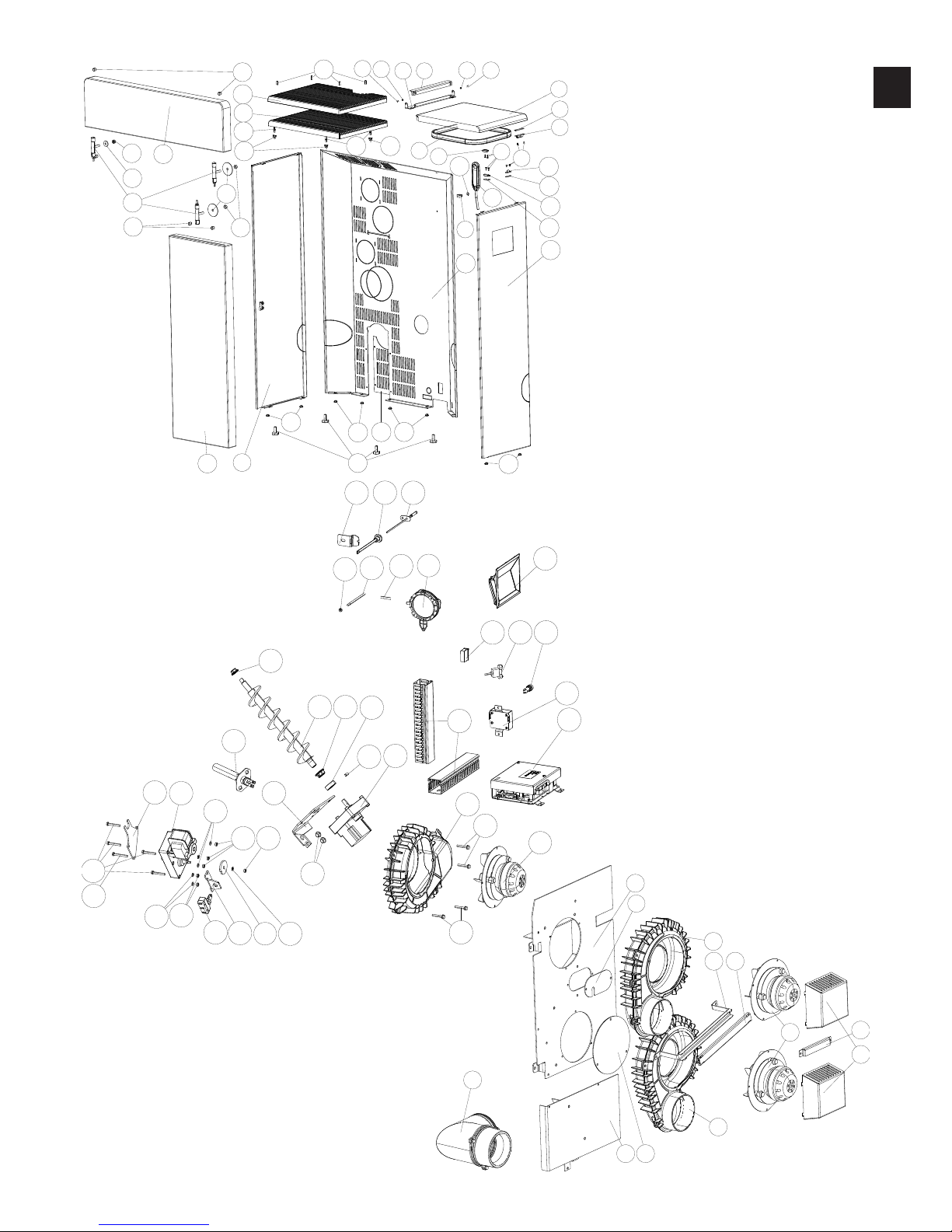
Spare part overview exploded diagram .....................................................................................................................................................4
Spare part overview article numbers .........................................................................................................................................................6
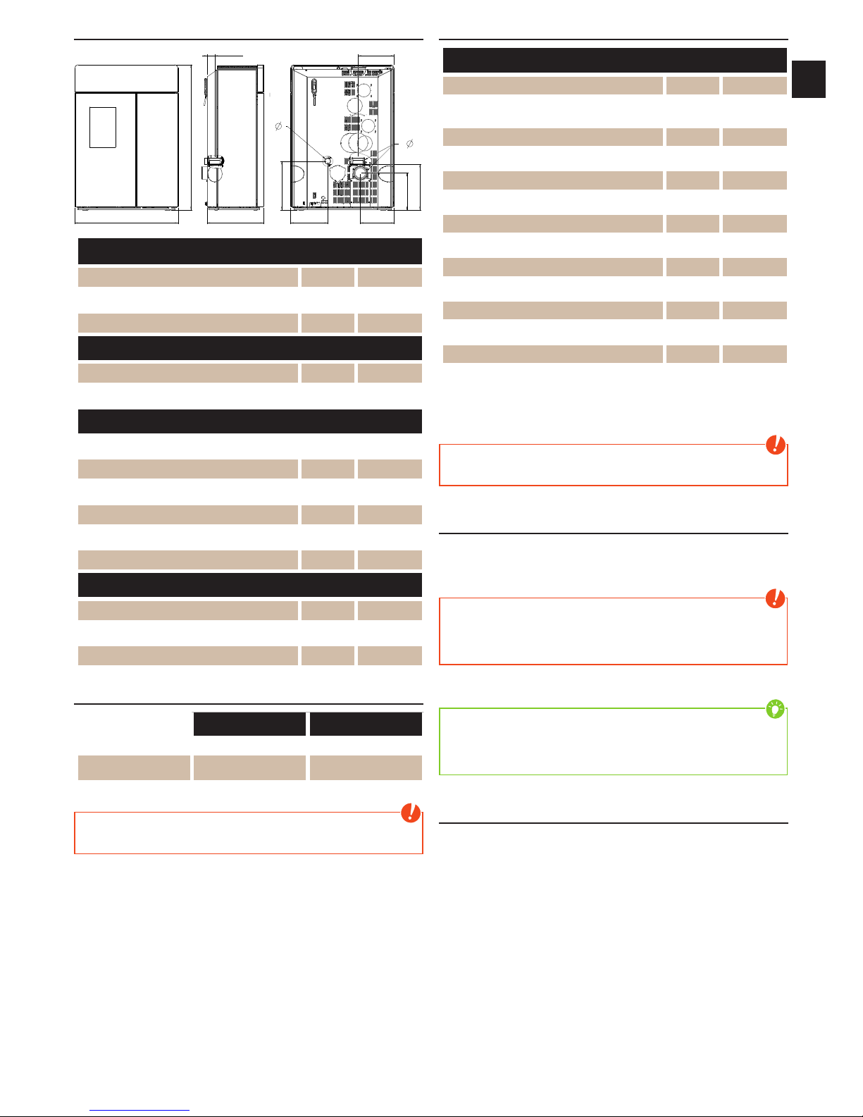
Dimensions ..............................................................................................................................................................................................7
Amount of fuel .........................................................................................................................................................................................7
Technical data ...........................................................................................................................................................................................7
Packaging .................................................................................................................................................................................................7
Electrical connection ................................................................................................................................................................................7
2. IMPORTANT INFORMATION 8
General warning and safety information ..................................................................................................................................................8
First heating..............................................................................................................................................................................................8
Safety distances ........................................................................................................................................................................................8
Prior to set up ...........................................................................................................................................................................................9
e correct chimney connection ...............................................................................................................................................................9
3. BRIEF INFORMATION ON FUEL - PELLETS 10
What are pellets? ....................................................................................................................................................................................10
Wood pellet specification according to ENplus – A1 .............................................................................................................................10
Pellet container refilling during operation ..............................................................................................................................................10
Pellet storage ..........................................................................................................................................................................................10
4. TECHNOLOGY AND SAFETY FUNCTIONS 11
Operating comfort ..................................................................................................................................................................................11
Top efficiency - lowest emissions ............................................................................................................................................................11
Pressure monitoring ................................................................................................................................................................................11
Low-temperature shutdown ...................................................................................................................................................................11
Electrical excess current protection .........................................................................................................................................................11
Automatic cleaning cycle ........................................................................................................................................................................11
Component monitoring .........................................................................................................................................................................11
Auger motor monitoring ........................................................................................................................................................................11
Power failure (during heating) ................................................................................................................................................................11
Power failure (during the initial stage)....................................................................................................................................................11
5. INSTALLING THE STOVE 12
General information ...............................................................................................................................................................................12
Connection to the chimney ....................................................................................................................................................................12
Connecting to a steel chimney ...............................................................................................................................................................12
Combustion air .......................................................................................................................................................................................12
Feeding in external combustion air .........................................................................................................................................................12
6. ASSEMBLY/DISMANTLING STONE AND OPTIONS 13
Converting to top connection rear R6 and top connection rear in the center R5 ...................................................................................13
Converting to side connection R3 + R4 and connection rear in the center R2 .......................................................................................14
Assembly/Dismantling stone..................................................................................................................................................................15
Page 3

|
3
EN
2
1. PREFACE
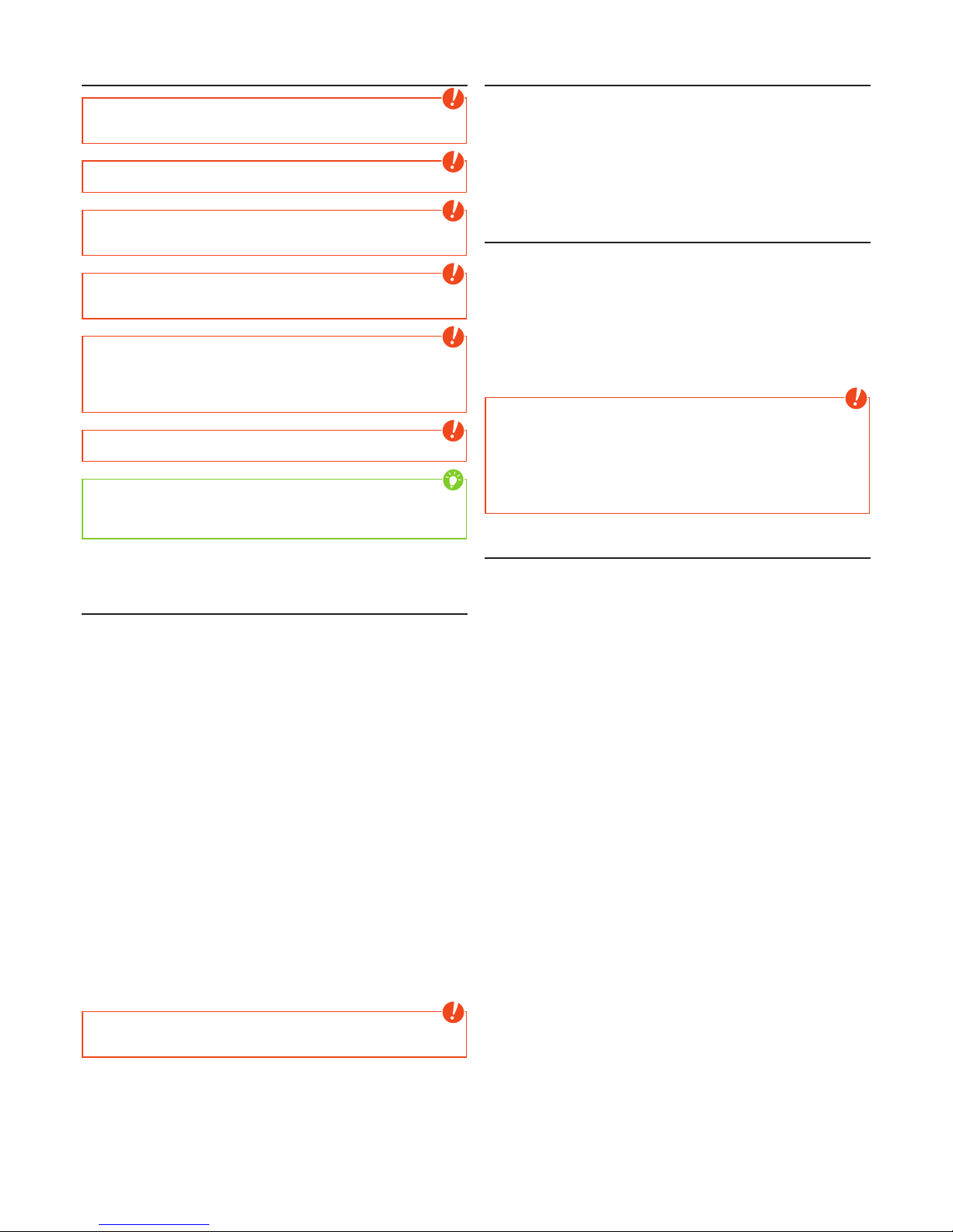
Explanations to symbols
...important
Note
#8
...Hex
#6, #8, #13
#6
...Allen Key
#2,5; #6
... Hexalobular
T25
...useful
Tip
...Hacksaw ...manually
#25
7. COMFORT OPTIONS 16
RIKA room sensor/RIKA radio room sensor .........................................................................................................................................16
RIKA GSM Control ..............................................................................................................................................................................16
RIKA interface for various options .........................................................................................................................................................16
External room thermostat ......................................................................................................................................................................16
External connection cable bridge ...........................................................................................................................................................16
Option RIKA firenet ..............................................................................................................................................................................16
8. CLEANING AND MAINTENANCE 17
Basic information ...................................................................................................................................................................................17
Open the combustion chamber door ......................................................................................................................................................17
Cleaning the fire trough .........................................................................................................................................................................17
Cleaning the flame temperature sensor ..................................................................................................................................................17
Empty the ash drawer .............................................................................................................................................................................17
Cleaning the door glass ..........................................................................................................................................................................17
Cleaning painted surfaces .......................................................................................................................................................................17
Cleaning flue gas paths ...........................................................................................................................................................................18
Cleaning the convection air openings .....................................................................................................................................................19
Combustion air - intake .........................................................................................................................................................................19
Cleaning the pellet container ..................................................................................................................................................................19
Cleaning the flue gas channels................................................................................................................................................................19
Checking door seal .................................................................................................................................................................................19
Bearings ..................................................................................................................................................................................................19
9. PROBLEMS - POSSIBLE SOLUTIONS 20
Problem 1 ...............................................................................................................................................................................................20
Problem 2 ...............................................................................................................................................................................................20
Problem 3 ...............................................................................................................................................................................................20
10. INSTRUCTIONS FOR COMMISSIONING PROTOCOL 21
11. GUARANTEE 23
Page 4
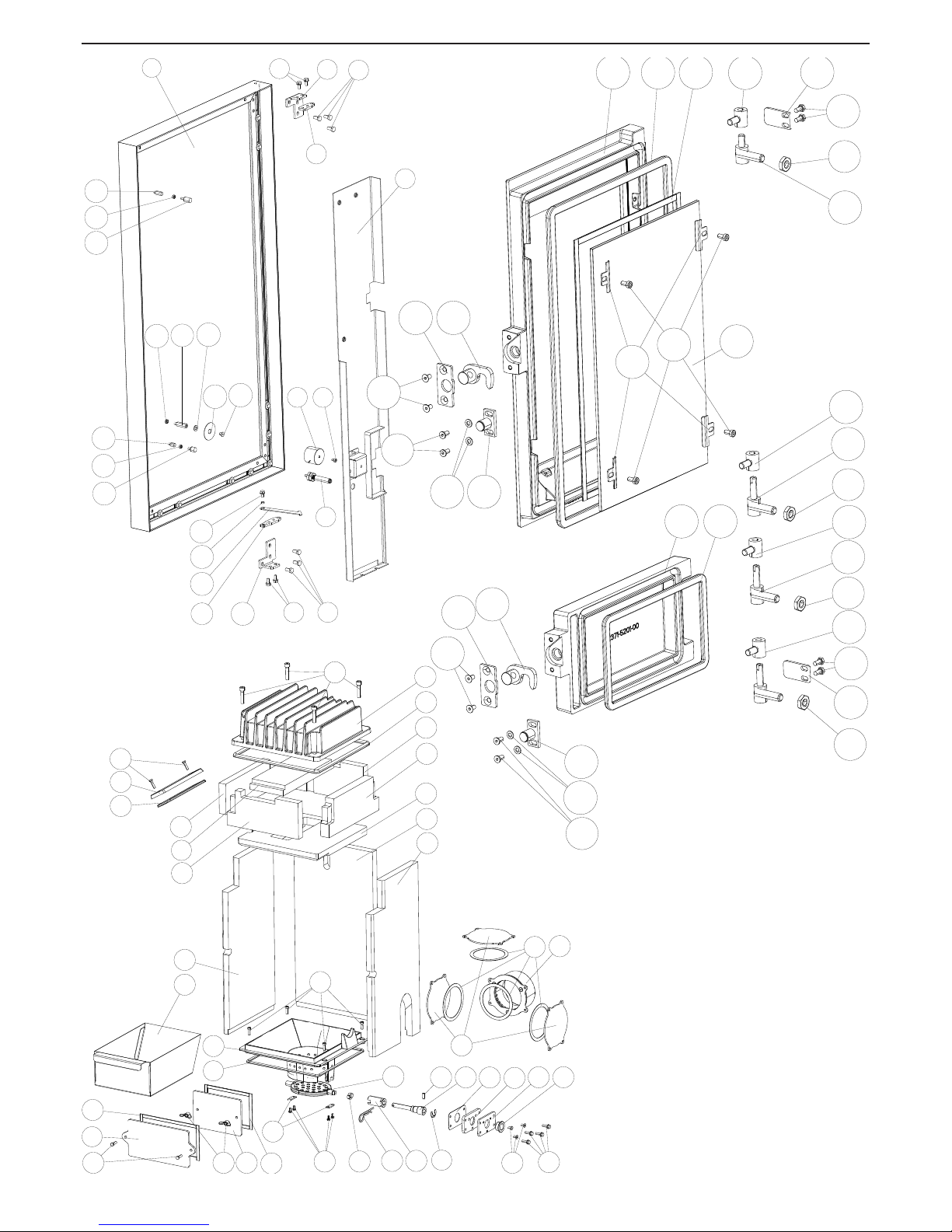
Spare part overview exploded diagram
6
9
7
8
341 041 125
2
1
1 2
1 3
1 4
1 7
1 6
1 5
20
21
22
23
24
1 9
1 6
1 8
7 9
7 8
80
82
81
83
85
86
87
6 0
6 3
6 4
6 1
6 2
5 7
5 8
5 9
5 4
5 6
5 5
5 3
4 9
4 8
5 2
5 0
5 1
4 6
4 7
7 4
7 5
7 3
7 6
7 0
6 9
7 1
7 7
6 6
6 8
6 7
84
6 5
4 5
7 2
3 1
3 1
3 9
4 0
4 1
3 9
4 0
4 1
29
29
3 0
3 0
25
27
3 6
3 4
26
4 2
4 3
4 4
3 1
3 1
3 7
3 8
4 2
4 3
4 4
3 3
3 3
3 2
28283 5
28
28
Page 5
|
5
EN
4
1 4 7
1 4 6
1 4 5
1 4 8
1 4 9
1 29
1 28
1 5 8
1 5 6
1 5 7
1 5 5
1 5 4
1 5 2
1 5 0
1 5 0
1 28
1 28
1 5 1
1 5 0
1 28
1 5 3
1 4 4
1 4 2
1 4 3
1 3 9
1 4 1
1 4 0
1 4 0
1 3 7
1 3 6
1 3 1
1 3 0
1 3 5
1 3 4
1 26
1 27
1 25
1 3 3
1 3 2
1 3 8
1 23
1 23
1 0 3
1 0 2
9 6
1 0 5
1 0 4
9 8
1 0 8
1 0 9
1 0 7
1 0 7
9 9
1 0 0
1 0 7
1 0 7
1 1 2
1 1 3
9 2
89
89
88
88
9 4
9 5
9 3
9 7
1 21
1 22
1 22
1 1 0
1 0 1
1 20
1 24
9 0
9 1
1 1 1
1 0 6
1 1 8
1 1 9
1 1 5
1 1 6
1 1 7
1 1 4
1 1 4
1 7 0
1 7 7
1 7 2
1 7 5
1 7 8
1 7 2
1 7 1
1 7 3
1 7 4
1 7 6
1 7 9
1 80
Page 6

Spare part overview article numbers
Nr. Art.Nr.: Description
1 B17412 Decorative door cpl.
2 N108313 Taptite
3 Z35993 Door mounting plate
4 N110032 Hexagonal screw
5 Z35992 Hinge
6 *1 B17967 Cover plate
*2 Z36172 Cover plate
7 Z36171 Electromagnet
8 N112163 Hexagon socket screw
9 B17521 Pressure spring
10 Z35995 Door mounting plate
11 Z35996 Hanger plate
12 L02651 Door stop plate
13 Z27866 Distance
14 N108121 Taptite
15 N112111 Rubber buffer
16 N111975 Hexagonal nut
17 N112173 Distance
18 N112110 Rubber buffer
19 N112174 Distance
20 N111973 Hexagonal nut
21 N112073 Distance
22 N112175 Washer
23 L02714 Magnet washer
24 N112176 Hexagonal countersunk screw
25 Z35464 Front door black
26 N100485 Round sealing strip D12
27 N103693
Culimeta flat packing black
8x2
28 B17524 Hinged belt black
29 L02645 Door stop base plate
30 N111950 Hexagonal screw M05x10
31 N111780 Hexagonal nut
32 B17405 Hinge
33 B15825 Hinge BA1
34 L00475 Glass holder
35 N112178 Hexagon socket screw
36 Z35856 Front door glass
37 Z35465 Front door black cpl.
38 N100476 Sealing cord black Ø10mm
39 B12322 Door lock
40 N111965 Washer D05
41 N108485 Allen screw
42 B17407 Shutter
43 L02647 Closure plate
44 N100242 Allen screw
45 N112047
Hexagon socket screw
M08x35
46 B17416
Combustion chamber cover
black
47 N100476 Sealing cord black Ø10mm
48 Z36576 Cast rear panel black
49 Z36602 Fire brick right
50 Z36601 Fire brick left
51 Z35850 Fire brick cover
52 Z35848 Fire brick front
53 Z35845 Flue plate
54 Z35842 Front liner rear
55 Z35844 Fire brick right
56 Z35843 Fire brick left
57 N100475
Culimeta flat packing black
8x2
58 B17486 Pipe adapter
Nr. Art.Nr.: Description
59 Z35997 Cooking cover
60 Z35463 Recess
61 N111631
Round sealing cord grey
Ø6mm
62 N112058 Allen screw
63 Z35808 Grid
64 L02726 Small plate
65 N111835 Hexagonal screw
66 L01875 Driving plate dump grate
67 N111538 Spring plug
68 Z35854 Intermediate shaft dump grate
69 N111058 Setscrew with pin
70 Z35855 Drive shaft
71 N112125 Shaft securing device
72 Z36167 Ceramic seal
73 Z35852 Bearing clamping plate
74 Z35851 Bearing plate
75 N102688 Sinter bearing ID16
76 N108485 Allen screw
77 N111947 Taptite
78 Z35999 Cleaning cover
79 Z36567 Sealing
80 N108306 Wing nut
81 Z36000 Cleaning cover
82 Z36566 Sealing
83 N112140 Hexagonal screw
84 L02658 Ash drawer
85 Z35632 Cleaning opening
86 N103066 Round sealing strip D06
87 N111866 Hexagonal screw
88 N111859 Allen screw
89 Z34696 Distance
90 Z35865 Hinge for container cover
91 Z36174 Stop rail
92 Z35975 Container lid black
93 N112126 Seal
94 L01446 Lock washer
95 N110461 Double ball catch
96 N111459 Allen screw
97 N111732 Magnetic switch upper section
98 N111842 Hexagon socket M03x10
99 Z35691 Spring plug
100 N112136 Taptite
101 N112018 Key
102 N110461 Double ball catch
103 L01502 Lock washer
104 N111733 Solenoid switch lower part
105 L01445 Switch distance
106 L02718 Side casing panel, right
107 N111730 Grommet
108 L02652 Rear wall black
109 L02653 Rear wall cover black
110 N111773 Levelling screw
111 L02715 Side casing panel, left
112 Z35656 Side casing soapstone right
Z35647 Front stone white right
Z35877 Front sandstone right
113 Z35655 Upper soapstone
Z35648 Upper stone white
Z35878 Upper sandstone
114 N112179 Grub screw
115 B17390 Stone retainer cpl.
116 N111843 Washer D08
Nr. Art.Nr.: Description
117 N100150 Hexagonal nut
118 L02239 Cover plate
119 N111683 Self-locking nut
120 Z36038 Convection cover RAO
121 Z35974 Convection cover AH
122 N112127 Locking bolt
123 Z36001 Snap spring
124 N111803 Grub screw
125 L01441 Pressure bracket
126 B16053 Sensor tube
127 B16114 Temperature sensor
128 N106175 Hexagonal nut
129 Z35096 Pressure Pipes
130 N111551 Silicon hose
131 N112102 Pressure difference guide
132 B16574 Touch-Display
133 N112016 Power switch
134 N111989 USB cable
135 N111604 Fuse 2,5A
136 B16030 Add. board mot. hor.
137 B16561 Mainboard USB11
138 Z35943 Cable channel
139 B16951 Induced draft fan housing
140 N111641 Taptite
141 N111581 Induced draught fan motor
142 N112030 Screw motor, stepless
143 N111058 Setscrew with pin
144 Z11915 Lock ring conveyer screw
145 Z35182 Plastic bearing
146 B12301 Auger
147 Z35183 Sintered bearing Di10
148 L00797 Motor plate
149 Z18997 Rubber buffer
150 N111965 Washer D05
151 L02646 Setscrew dump grate contact
152 L02644 Retaining plate
153 N111825 Door contact switch
154 N101570 Hexagonal screw
155 N111806 Hexagonal screw
156 L02643 Motor plate
157 N112014 Turning grid motor cpl.
158 B17166 Ceramic ignition
B17411 Cabletree Domo
Z35018 Cable 2m for touch-display
MultiAir and connect rear centre
170 LB00629 Fan holder
171 L02721 Cover plate sensor
172 B17370 Induced draft fan housing
173 L02722 Cable duct
174 L02723 Cover cable duct
175 N112000 Convection fan motor
176 L02724 Motor protection cover
177 L02725 Cover plate
178 LB00630 Air guide blade
179 Z36002 Cable cover
180 E15634 Connecting bend cpl.
*1 up to serial number 1354983
*2 from serial number 1354984
Note: Please consider the powdercoated parts can differ slightly in colour and colour effects though they are elaborated in high quality.
Page 7
|
7
EN
6
Dimensions
F - H
F - S R - S
R - H
B
H
T
R O - SR O - T 3
R O - H
R -
F -
Dimensions
Height [mm] 1115
Width [mm] 793
Corpus Depth [mm] 433
Weight
Weight without Shell [kg] 205
Weight with Shell [kg] 255
Flue pipe connection
R - Ø Flue Pipe Outlet [mm] 100
R - H Rear Connection Height [cm] 28
R - S Rear Connection - side Distance [cm] 26
RO - H Top connection Height [cm] 37
RO - T3 Top connection - Distance to rear wall [cm] 6
RO - S Top connection - side Distance [cm] 28
Fresh air connection
F - Ø Diameter [mm] 50
F - H Connection Height [cm] 37
F - S Side Distance [cm] 28
Amount of fuel
Nominal load Part load
Amount of fuel ~2,4kg* ~0,8kg*
Burn time at full pellet
hopper
ca. 20h ca. 60h
*Practical values may vary depending on pellet quality.
Note
Pellet consumption depends on the size of the pellets. The larger the pellet,
the slower the feed and vice versa.
Technical data
Technical data
Heating power range [kW] 3-10
Room heating capacity (depending on house
insulation)
[m³] 70-260
Fuel consumption [kg/h] bis 2,4
Pellet container capacity [l]/[~kg] 76/~50
Electric supply [V]/[Hz] 230/50
Average electrical input [W] ~ 20
Fuse [A] 2,5 AT
Efficiency [%] 92,7
CO2 [%] 11,8
CO-emission on 13% OO [mg/m
N
3
] 46
Dust emission [mg/m
N
3
] 18
Exhaust [g/s] 6,6
Exhaust temperature [°C] 135,5
Chimney draft requirement [Pa] 3
The owner of small firing systems or the person authorised for the small
firing system is to keep the technical documentation and is to submit it to the
authorities or the chimney sweep on request.
Note
Please observe the national and European standards as well as local
regulations concerning the installation and operation of firing installations!
Packaging
Your first impression is important to us!
The packaging of your new stove provides excellent protection against damage.
However damage to the stove and accessories may still occur during transport.
Note
Therefore please check your stove on receipt for damage and completeness!
Report any deficiencies to your dealer immediately! Pay particular attention
during unpacking that the stone panels remain intact. Scratches to the
material can easily occur. Stone panels are excluded from the warrant.
The packaging of your new stove is environmentally neutral to a great extent.
Tip
The wood used in the packaging has not been surface treated and may
therefore be burnt in your woodburning stove (not in pellet stoves!). The
cardboard and film (PE) can be depolluted via the municipal waste collection
for recycling.
Electrical connection
The stove is supplied with an approx. 2m long connecting cable with a Europlug. This cable is to be connected to a 230Volt/50Hz socket. The average
electrical power consumption is about 20 Watt in heating operation and approx.
150 Watt during automatic ignition. The connection cable must be laid in a way
that there is no contact to any sharp edges or hot surfaces of the stove.
Page 8
2. IMPORTANT INFORMATION
General warning and safety information
Observance of the introductory general warning information is imperative.
Q Read the entire manual thoroughly before installing and putting the stove into
service. Observe the national provisions and laws as well as the regulations
and rules applicable locally.
Q RIKA stoves should only be installed in rooms with normal humidity (dry
areas according to VDE 0100 Part 200). The furnaces are not splash water
protected and may not be installed in wet areas.
Q Only approved transport equipment with sufficient load carrying capacity
may be used with your heating appliance.
Q Your heating appliance is not suitable for use as a ladder or stationary
scaffolding.
Q The burning of fuel releases heat energy that lead to extensive heating of
the stove surfaces, doors, door and operating handles, glass, flue pipes
and possibly the front wall. Refrain from touching these parts without
appropriate protective clothing or equipment e.g. heat-resistant gloves or
means of operation (operating handle).
Q Make your children aware of this particular danger and keep them away from
the stove during heating.
Q Only burn approved heating materials.
Q The combustion or introduction of highly flammable or explosive materials
such as empty spray cans etc. in the combustion chamber and storing them
near the stove is strictly prohibited due to the danger of explosion.
Q No light or inflammable clothing is to be worn when post-heating.
Q Use the heat-resistant gloves supplied to open the doors of your stove.
Q Make sure that no embers fall out of the combustion chamber onto
inflammable material.
Q Placing non-heat resistant objects on the stove or near it is prohibited.
Q Do not place clothing on the stove to dry.
Q Laundry racks etc. must be placed at a sufficient distance to the stove –
ACUTE DANGER OF FIRE!
Q When your stove is burning, the use of highly inflammable and explosive
materials in the same or adjacent rooms is prohibited.
Q Pellet stoves are generally designed and developed to operate as an
additional heat source (supplementary heating). The cleaning, as well as the
information about the wear are set accordingly in our manual. If the stove is
heated in continuous operation, the cleaning intervals are shorter. Increased
wear, especially of the thermally stressed parts, is the result. Please
therefore strictly follow the requirements for cleaning and maintenance!
Note
Waste and liquids may not be burnt in the stove!
Note
To prevent your stove from overheating of the internal components,
do never cover the convection fins!
Note
CAUTION when filling the pellet container. The opening of the pellet container
is sufficiently dimensioned to ensure easy filling. Take great care that no
pellets drop to the convection fins and the hot stove body. This can cause a
lot of smoke.
Tip
Therefore we recommend refilling the pellet container at a cold stove.
Note
Your stove will expand and contract during the heating and cooling phase.
This can sometimes lead to slight bending or cracking noises. This is normal
and is no reason for a complaint.
First heating
The stove body, just as various steel parts, cast iron parts and the flue pipes
are painted with a heat resistant paint. During the first heating the paint dries
out completely. This may cause a slight smell. Touching or cleaning the painted
surfaces during the curing should be avoided. The hardening of the paint is
finished after the first heating with high power.
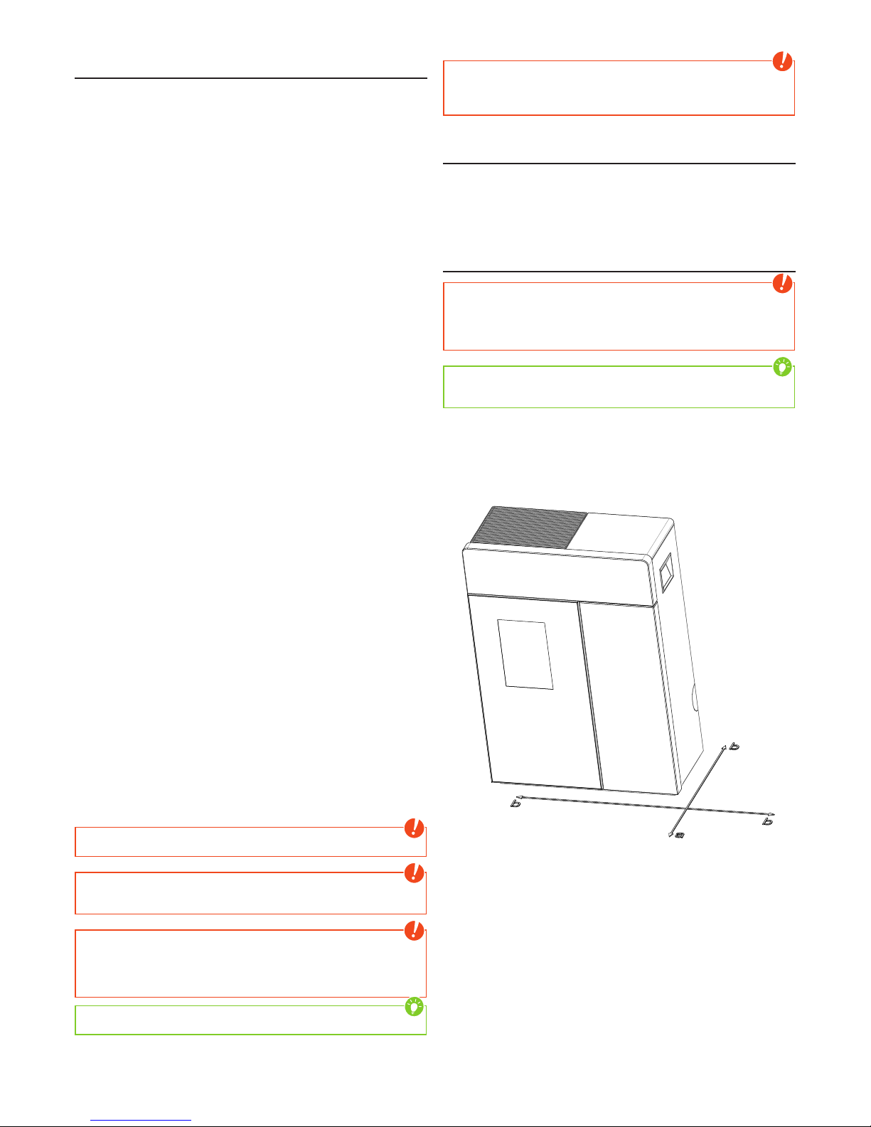
Safety distances
Note
1. To non-combustible objects
a > 40 cm b > 10 cm
2. To combustible objects and reinforced concrete load-bearing walls
a > 80 cm b > 10 cm
Tip
please observe a minimum distance of 20 cm behind and sideways the stove
for maintenance.
Page 9
|
9
EN
8
Prior to set up
Floor bearing capacity
Ensure that the substructure is capable of bearing the weight of the stove prior
to set-up.
Note
No modifications may be made to the firing installation. This also leads to loss
of warranty and guarantee.
Floor protection
A base is recommended (glass, sheet steel or ceramic) if the floor is combustible
(wood, carpet, etc.). Please observe the respective local regulations and rules.
Flue pipe connection
Q Flue pipes pose a particular source of hazard regarding gas leaks and
fire. Get the advice of an authorised specialist company for the layout and
assembly.
Q Please observe the corresponding installation guidelines for walls panelled
with wood when connecting your flue pipes to the stove.
Q Observe the formation of flue gas (atmospheric inversion) and draughts
when the weather is unfavourable.
Q Infeed of too little combustion air can lead to smoke in the rooms or to flue
gas leaks. Hazardous deposits in the stove and chimney may also occur.
Q If flue gas escapes, let the fire burn out and check whether all the air inlet
openings are free and the flue gas pipes and the stove pipe are clean. If in
doubt notify the master chimney sweep since draught malfunctions may be
connected to your chimney.
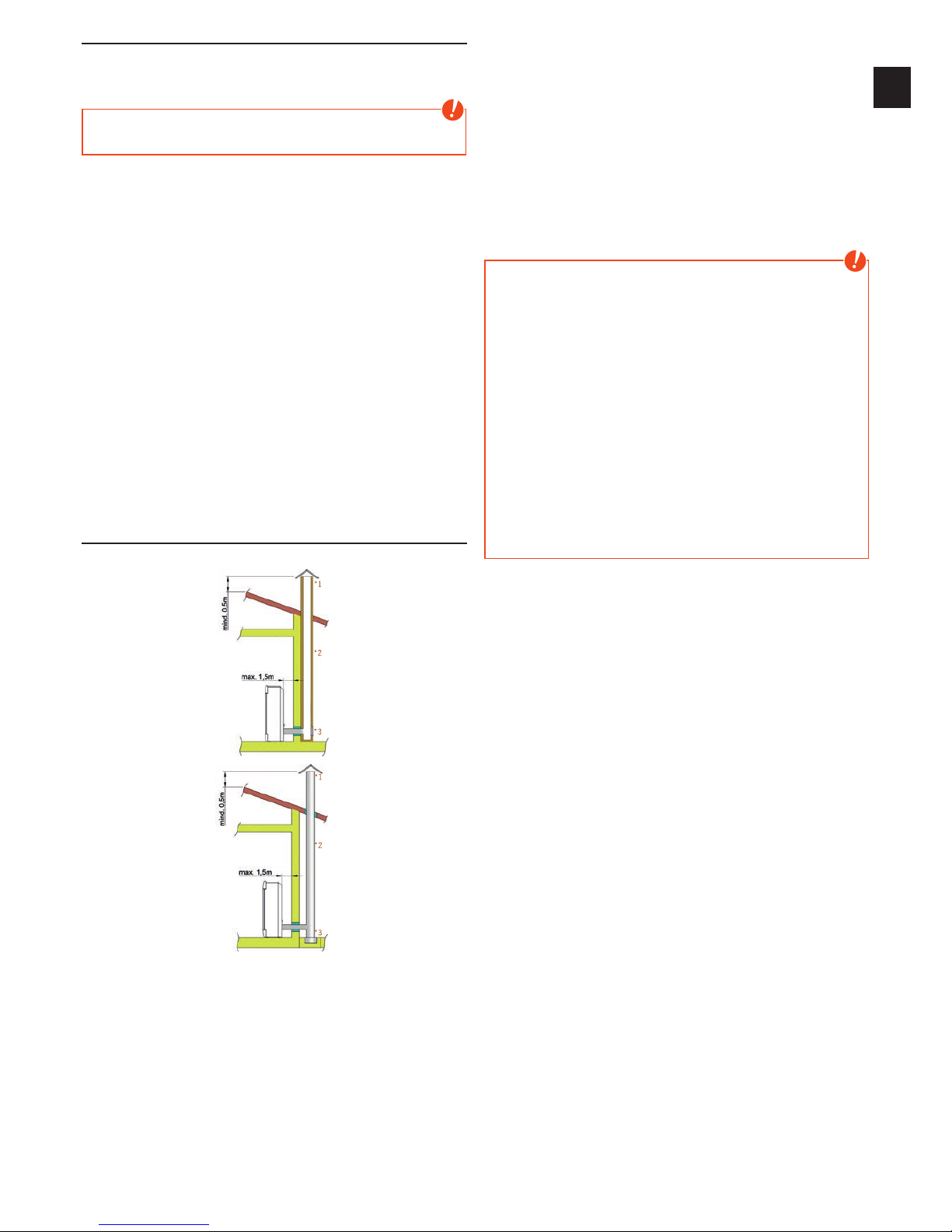
The correct chimney connection
There are several ways to connect your stove to the chimney, eg:
*1
*2
*3
*1
*2
*3
1) wind break, 2) chimney, 3) inspection opening
For the selection of the connection and to ensure a proper connection between
the stove and chimney, please read the guide „INSTALLING THE STOVE“ or ask
your local chimney sweep.
Stoves type 1 (BA 1):
Q Suitable for multiple occupancy. (Note the different country regulations.)
Q These may only be operated with the combustion chamber door closed.
Q The combustion chamber door is to be kept closed when the stove is not
in operation.
Q Fouling of the chimney i.e. deposits of highly inflammable materials such as
soot and tar and subsequently fire in the chimney may occur if the chimney
is miscalculated and dimensioned wrong.
Q If this occurs, disconnect the mains plug. Phone the fire brigade and get
yourself and other residents out of harm’s way.
Note
Your pellet stove can be operated room air dependent or room air independent.
ROOM-AIR INDEPENDENT OPERATION:
The stove is certificated for type FC52x of the approval principles for the
inspection and evaluation of ambient air independent fireplaces specified by
the Deutsches Institut für Bautechnik (DIBT) (German Institute for Building
Technology). Thanks to an air-tight configuration of the air supply line and flue
pipes the stove may be operated in air-tight rooms and in rooms with room-air
installations (e.g. controlled ventilation and venting systems, extractors etc.).
ROOM-AIR DEPENDENT OPERATION:
In combination with room-air installations (e.g. controlled ventilation and
venting systems (extractors etc.) it must be ensured that the stove and
the room air system are monitored and safeguarded mutually (e.g. via
a differential pressure controller). The combustion air infeed of approx.
20 m3/h must be ensured.
Please observe the respective local regulations and rules in consultation with
your master chimney sweep. For changes after the printing of this manual, we
can not assume any liability. We reserve the right to change without notice.
Page 10
3. BRIEF INFORMATION ON FUEL - PELLETS
What are pellets?
Wood pellets are a standardised fuel. Every manufacturer must adhere to certain
conditions in order to enable flawless, energy-efficient heating. Pellets are made
from wooden waste, from sawmills and planning workshops, as well as from
residue from forestry operations. These “starting products” are crushed, dried,
and pressed into Pellet “Fuel” without any bonding agent.
ENplus – Pellets
This new pellets are a standard sets new benchmarks in the European pellet
market. The traceability of pellets is ensured thanks to the use of identification
numbers. The pellet manufacturers’ production facilities and manufacturing
processes are reviewed every year. A quality assurance system ensures
the pellets comply with the requirements of the new standard and that the
conditions for trouble-free heating are guaranteed
Wood pellet specification according to ENplus –
A1
Parameter Measure ENplus-A1
diameter mm 6 (±1)
2)
length mm 3,15 bis 40
3)
buld density kg/m³ ≥600
calorific value MJ/kg ≥16,5
water content Ma.-% ≤10
fine fraction (<3,15mm) Ma.-% ≤ 1
mechanical rigidity Ma.-% ≥97,5
4)
ash content Ma.-%
1)
≤0,7
ash softening temperature (DT) °C ≥1200
chlorine content Ma.-%
1)
≤0,02
sulphur content Ma.-%
1)
≤0,03
nitrogen content Ma.-%
1)
≤0,3
copper content mg/kg
1)
≤10
chrome content mg/kg
1)
≤10
arsenic content mg/kg
1)
≤1
cadmium content mg/kg
1)
≤0,5
mercury content mg/kg
1)
≤0,1
lead content mg/kg
1)
≤10
nickel content mg/kg
1)
≤10
zinc content mg/kg
1)
≤100
1) in an anhydrous state
2) diameter must be specified
3) a maximum of 1% of the pellets may be longer than 40 mm,
max. length is 45 mm
4) the limit value of ≥97,7 Ma.-% applies when conducting measurements with a
lignotester (internal control)
Your pellet stove is only approved for the burning of pellets of tested quality.
Please ask your pellet stove dealer for tested fuel and a list of monitored fuel
manufacturers.
Note
Only burn pellets that have been inspected according to ÖNORM, DIN Plus
or ENplus-A1. Using poor quality or prohibited pellet fuel will have a negative
effect on the function of your pellet stove and can also lead to the warranty
becoming null and void, as well as the product liability connected with this.
Note
Burning straw, maize, woodchips etc. is not permitted! Observe waste
incineration legislation! Non-observance of these regulations makes void all
warranty and guarantee claims and may impair the safety of the unit!
Pellet container refilling during operation
Note
CAUTION when filling! Avoid direct contact between the plastic bag and the
hot stove. Immediately remove all pellets that have fallen on the hot stove or
next to the container!
We recommend always having a suitable amount of pellets in the container
to prevent the fire from extinguishing due to a lack of fuel. Check the level
frequently. However the container lid should be kept closed, except during
filling.
If you refill the container during operation (open the container lid), the fan will
speed up and the pellet auger will stop; operation will only be continued once
the container lid is closed again (see WARNING AND ERROR MESSAGES)
Pellet container capacity (see Technical Data).
Pellet storage
In order to guarantee problem free burning of the wooden pellets, it is imperative
necessary to store the fuel as dry as possible and free from impurities.
Pellets should not be kept in sacks outdoors or stored in a manner where
they are exposed to the environment. This can lead to blockages in the screw
conveyor.
Note
“Screw stoppers” are excluded from the warranty.
Page 11
|
11
EN
10
4. TECHNOLOGY AND SAFETY FUNCTIONS
The technological advances in your new combi stove are the result of years of
testing and practical experience. The practical advantages of your pellet stove
are convincing:
Operating comfort
The microprocessor-controlled combustion regulation optimises the interaction
of flue gas blower and screw using the current combustion chamber
temperature. This guarantees optimum combustion and operating status.
All function can be regulated centrally using the integrated operating unit. The
intuitive graphic interface permits easy operation; all the settings can be made
quickly and simply.
Top efficiency - lowest emissions
A very great heat exchange surface together with optimum combustion air
control leads to excellent fuel utilisation.
Fine continuous pellet dosing in an optimised burner pot made of high-quality
grey cast iron leads to virtually complete combustion with very good exhaust
gas values - and this is guaranteed in every operating phase.
Note
The automatic control system means that during operation, the flame noise,
pellets dropping and actuation of the electronic components permissible for
living spaces are audible.
Pressure monitoring
The negative pressure in the combustion chamber is continuously monitored
during operation. Below a defined threshold, a correct operation can not be
guaranteed and the unit will switch off with the fault message „NOT ENOUGH
LOW PRESSURE“ for safety reason.
Note
After the occurrence of the error message, maintenance or cleaning work
necessarily has to be carried out! If the error occurs again, a safe operation is
no longer guaranteed, the service must be informed immediately.
Note
If the stove is used in a room together with a kitchen hood it might happen that
the built-in pressure switch stops the stove. If using the hood make sure make
sure that an adequate supply of air is ensured.
Low-temperature shutdown
The unit switches off if the stove cools below a minimum temperature. This
switch-off may occur if pellet ignition is delayed.
Electrical excess current protection
The stove has a main fuse (at the rear) to protect against excess current
Automatic cleaning cycle
The speed of the flue gas fan is increased every hour for a short period to blow
ash from the burn pot, increasing the operational safety. The status indicator
CLEANING appears on the display.
Only for stoves with turning grids:
Every 6 hours (interval adjustable) an additionally automatic cleaning cycle
is performed. The stove stops, the automatic cleaning tilts the grid and then
re-ignites the stove. The status indicator CLEANING appears on the display
continuously. The cleaning procedure with tilting the grid is to convey ash and
clinker from the burn pot into the ash drawer. This additional function does not
replace a manual cleaning as described in CLEANING and MAINTENANCE, as
this is absolutely necessary to do regularly.
Component monitoring
All the electrical components used are continuously monitored during operation.
If a component is defective or can no longer be actuated correctly, then
operation is stopped and a warning or error message is issued (see WARNING
AND ERROR MESSAGES).
Auger motor monitoring
Too long or wet pellets as well as pellets with too high dust content (see BRIEF
INFORMATION ON FUEL PELLETS) can cause so-called “auger jammers” in the
auger channel. This may also happen if the pellets accumulate in the burn pot
and the backlog reaches into the chute. The auger motor reacts in both cases
with an increased current consumption, which causes the error message:
DISCHARGE MOTOR BLOCKED. The stove will be stopped. Please call the
customer service immediately.
Power failure (during heating)
After a brief power failure, the operating functions that were set before the
power failure, continues. If the power failure lasts longer, the stove goes to start
phase if sufficient temperature or embers are present. If the power failure lasts
too long, the stove goes into the stop phase. The flue gas fan continues to burn
any pellet residues (approximately 10 minutes). Then it will restart automatically.
Power failure (during the initial stage)
After a brief power failure the boot process continues. If the power failure lasts
longer, the stove is in the stop phase. The flue gas fan continues to burn any
pellet residues (approximately 10 minutes). Then it will restart automatically.
Page 12
5. INSTALLING THE STOVE
General information
Note
Only use heat-resistant sealing materials as well as corresponding sealing
strips, heat-resistant silicon and rock wool.
Note
Assembly may only be performed by authorised specialist companies.
Note
Also take care that the flue does not project into the free cross-section of
the chimney.
Note
Please observe the regional safety and building regulations. Please contact
your master chimney sweep in this context.
Note
Your stove is intended for room-air independent operation. Thus the stove
pipe connections must be tightly sealed permanently for this use. Use a heatproof silicon to position the stove pipe on the conical supports of the flue tube
nozzles and for insertion in the chimney flue lining.
Note
The stove should not be pushed on unprotected floors.
Tip
Strong corrugated cardboard, cardboard or e.g. old carpet is useful to assist
assembly and as a base. The stove can also be pushed on this cardboard
or carpet.
We recommend original flue pipes from RIKA for proper connection.
Connection to the chimney
Q The device must be connected to an approved chimney for solid fuels.
The chimney must have a diameter of min. 100mm for pellet stoves and
130mm -150mm for log wood stoves depending on the diameter of the
flue pipes.
Q Avoid long flue pipes to the chimney. The horizontal length of the flue pipe
should not exceed 1.5 m.
Q Avoid to many bends of the flue gas pipes. There should not be more than
3 bends in the exhaust pipe.
Q If you just can not connect directly to the chimney, please use a connection
with a cleaning opening.
Q Connections must be made of metal and must meet the requirements of the
standard (install the connections airtight).
Q Before installing a chimney calculation must be made. The evidence must be
performed for single occupancy to EN13384-1 and EN13384-2 for multiple
occupancy.
Q The maximum draft of the chimney should not exceed 15Pa.
Q The derivation of the flue gases must be guaranteed even during a temporary
power outage.
Note
If connecting to multiple connection chimneys additional safety equipment is
required. Your local chimney sweep will advise you in this case.
Connecting to a steel chimney
The connection must be calculated and shown with EN13384-1
and EN13384-2.
Use only insulated (double) stainless steel tubes (flexible aluminum or steel
tubes are not permitted).
An inspection door for regular inspection and cleaning must be present.
The flue pipe connection to the chimney has to be air-tight.
Combustion air
Every combustion process requires oxygen from the surrounding air. This socalled combustion air is removed from the living are in the case of individual
stoves without external air connections.
This air removed must be replaced in the living space. Very tightly sealed
windows and doors in modern flats may mean that too little air replaces that
used. The situation also becomes problematical due to additional venting in
flats (e.g. in the kitchen or WC). If you cannot feed in external combustion air,
then air the room several times a day to prevent negativce pressure in the room
or poor combustion.
Note
Please note that problems may arise due to updrafts in the case of
combustion air supply from an integrated chimney ventilation shaft. If the
combustion air flowing downwards is heated it may rise and thus counter
the chimney with a resistance which in turn reduces the negative pressure
in the combustion chamber. The chimney manufacturer is to guarantee that
the resistance for the combustion air is a maximum 2 Pa even in the least
favourable operating state of the chimney.
Feeding in external combustion air
only for devices which are able to run in room-air independent operation.
Q Combustion air must be fed to the stove from outside via a sealed pipe
for operation independent of the room air. According to EnEV, it must be
possible to shut off the combustion air pipe. The open/closed setting must
be clearly recognisable.
Q Cut the perforated rear wall out with a hacksaw.
Q Connect at the air intake either a pipe Ø125mm (log wood and combi
stoves) or Ø50mm (pellet stoves) and fix it with a hose clamp (not included!).
At pellet stoves with longer intake pipes than 1m the diameter should be
increased to 100mm. (see RIKA range).
Q To ensure sufficient air intake, the intake pipe should not exceed max. 4m
and have max. 3 bends.
Q If the line leads outside it must have a windbreak.
Q In extreme cold pay attention to icing on the air intake opening (check).
Q It is also possible to suction in combustion air directly from another
sufficiently vented room (e.g. cellar).
Q The combustion air pipe must be tightly connected (adhesive or cement)
permanently to the air nozzles of the stove.
Q If you do not use the stove for a long time, please close the combustion air
intake to prevent the stove from moisture.
If one or more of these conditions does NOT apply, the result is poor combustion in the
stove and negative pressure in the installation room.
Page 13
|
13
EN
12
6. ASSEMBLY/DISMANTLING STONE AND OPTIONS
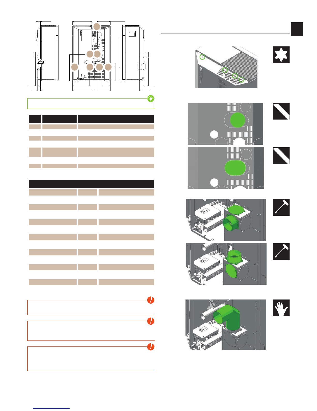
R H 1= R H 2= R H 3 = R H 4
R S 3
R S 4R S 2
R H 5= R H 6
R S 6= R O - SR S 5
R T 6
R T 5
R T 3
R T 4
R S 1
R O - H
R O - T 3
RO
R6R5
R4R3 R2 R1
Tip
Right / Left according to standing in front of the stove!
Nr. Connection Parts
R1 Rear R2 Rear center Domo-accessory elbow
R3 Right side range straight flue pipe*
R4 Left side range straight flue pipe*
R5
Rear center top
range
90 degree elbow with cleaning lid + 45°
elbow*
R6 Rear top range 90 degree elbow with cleaning lid*
RO Top range straight flue pipe*
*from the standard RIKA flue pipe
Dimensions of options flue gas connection
R1 = RH2 = RH3 = RH4 [cm] 28
RS1 [cm] 26
RS2 [cm] 36
RS3 [cm] 42
RT3 [cm] 7
RS4 [cm] 16
RT4 [cm] 6
RH5 = RH6 [cm] 53
RS5 [cm] 40
RT5 [cm] 11
RS6 = RO-S [cm] 28
RT6 [cm] 4
RO-H [cm] 37
RO-T3 [cm] 6
Note
Only work on the unit when the mains plug has been disconnected and the
stove has cooled completely.
Note
During assembly / dismantling do not allow objects (screws etc.) to fall into
the pellet container – they can block the screw conveyor and damage the
stove.
Note
During any conversion work, take particular care of your fingers and any
panels and stove attachments.
Select soft bases to prevent scratches to your living space furniture and
stove panels.
Converting to top connection rear R6 and top
connection rear in the center R5
Loosen the screws on the rear panel. The back wall tilts backwards and then
you can lift it off.
Cut with a saw along the marked perforation of the rear wall for the option you
need.
Replace the flue gas stack and the top cover against each other.
Place the elbow with cleaning lid to the flue gas stack. Make sure that everything
is tight!
#25
#8
#8
Page 14
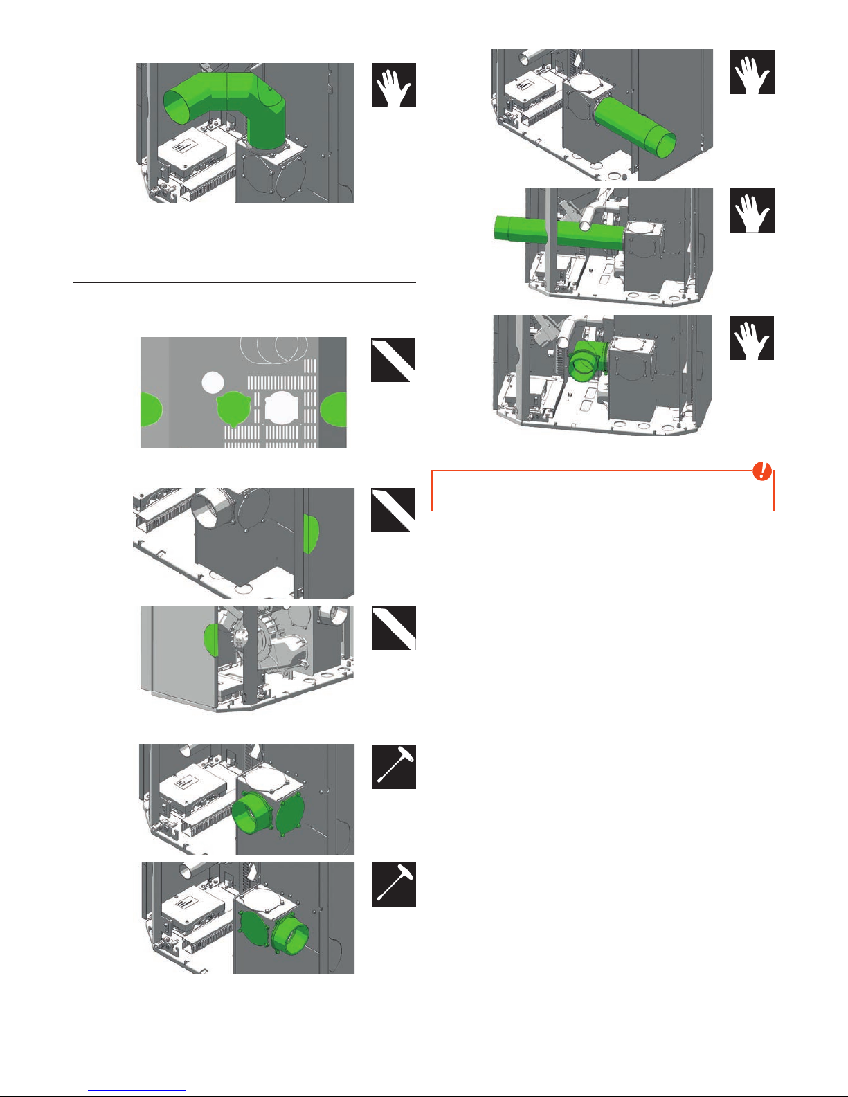
Put on a 90 degree elbow with cleaning lid and then another 45 degree elbow,
which has to be cut off about 4 cm, to reach the top center connection of the
flue gas pipe. Make sure that everything is tight!
Install the rear panel again.
Converting to side connection R3 + R4 and
connection rear in the center R2
Remove the rear panel as previously described.
Cut with a saw along the marked perforation of the rear wall for the option you
need.
Cut out one of the side panels of the stove along the marked perforation for
lateral option.
Replace the flue gas stack and one of the side cover plates against each other.
Place the correspondent flue pipe on the side. Make sure that everything is
tight!
Install the rear panel again.
Note
Protect all cables inside the stove from the heat! Improper installation can
damage your stove and void your warranty.
#8
#8
Page 15
|
15
EN
14
Assembly/Dismantling stone
Note
Only work on the unit when the mains plug has been disconnected and the
stove has cooled completely.
Note
During assembly / dismantling do not allow objects (screws etc.) to fall into
the pellet container – they can block the screw conveyor and damage the
stove.
Note
During any conversion work, take particular care of your fingers and any
panels and stove attachments.
Select soft bases to prevent scratches to your living space furniture and
stove panels.
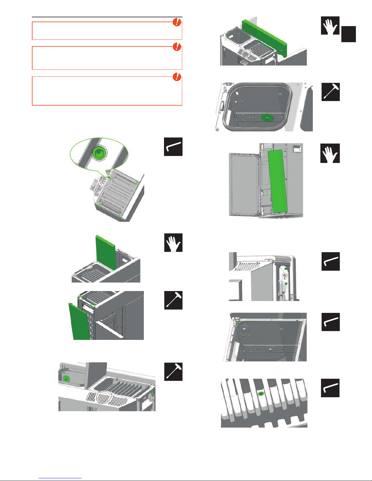
Open the decorative glass door by pushing the button on the display before you
unplug the stove from the power supply.
To remove the convection fins turn the 4 screws (marked) clockwise, the lid lifts
off. Then carefully remove the convection fins up.
Open the pellet container lid until it stops, in this position, it stays open.
Now remove the two hex screws on the side panel and lift the side wall.
Remove the self-locking hexagon nut including the covering plate which serves
to seal the pellet container, and the hex nut including the washer on the other
side.
Now you can take off the top stone to the front.
For the right front stone remove the self-locking hexagon nut including the
covering plate which serves to seal the pellet container.
Now lift the stone slightly and carefully lift diagonally forward.
Install the removed parts in reverse order.
With the green marked screws you can adjust the position of the stones, so that
the decorative glass door and the stones are flush in front. Afterwards you fix
the stones with the self-locking hexagon nuts.
Make sure before mounting the convection fins that the 4 screws (marked in
green) are flush.
Then carefully place the convection fins in the supposed recess and press down
firmly with your hand until the cover locks into place.
#2,5
#8
#13
#8
#6
#6
#2,5
Page 16
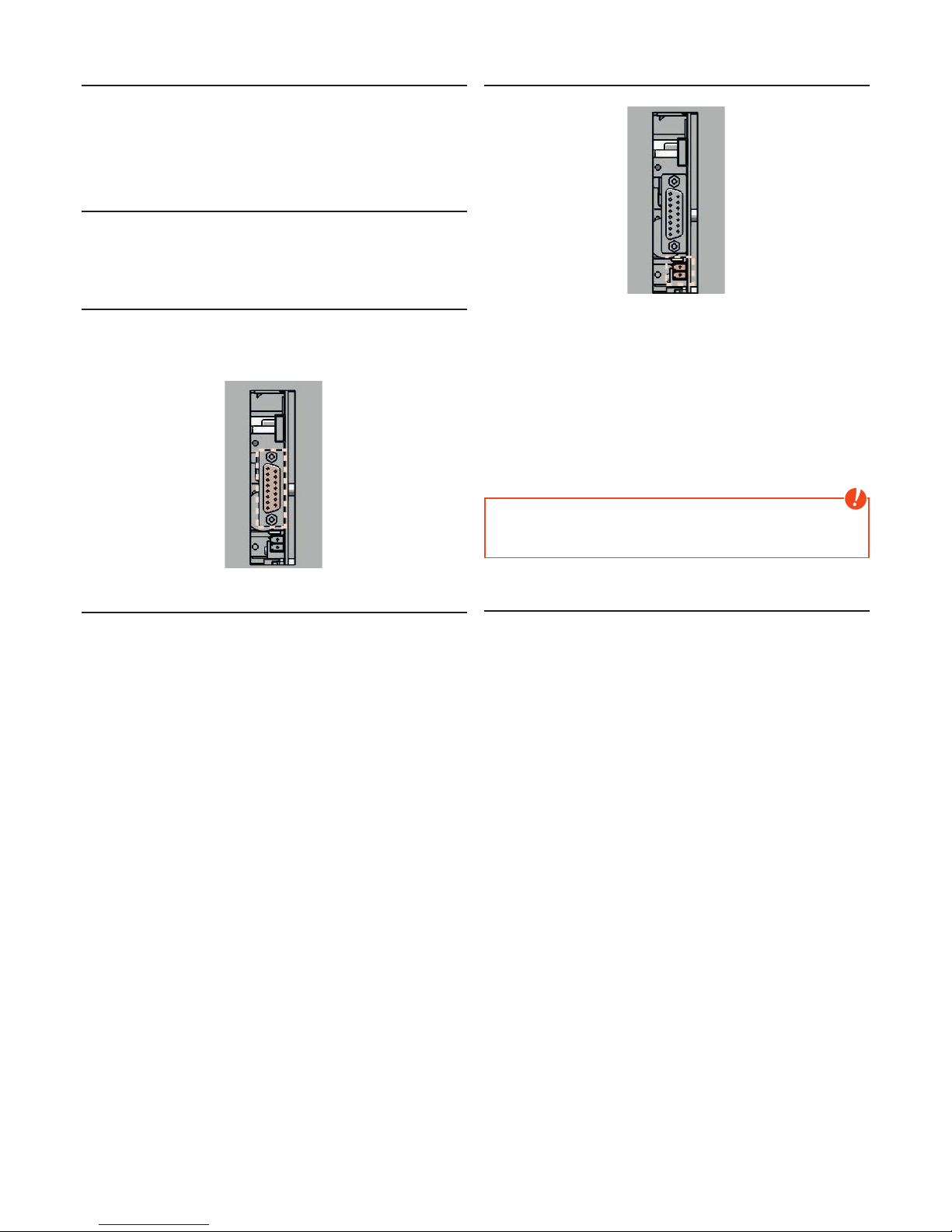
7. COMFORT OPTIONS
RIKA room sensor/RIKA radio room sensor
This option permits control of your stove via room temperature. You can set
both the room temperature and the heating times required. A room temperature
selected by you is observed during the heating times.
Please see the operating instructions for the option RIKA room sensor and
wireless room sensor for more detailed information.
RIKA GSM Control
Your stove can also be controlled via a mobile phone as an additional option.
Please see the operating instructions for the telephone option – GSM for more
detailed information.
RIKA interface for various options
for various options
The RIKA ROOM SENSOR, the RIKA WIRELESS ROOM SENSOR and the RIKA
PHONE OPTION – GSM are to be connected to the interface (stove rear) using
the connection cable supplied.
External room thermostat
Your stove has an interface on the rear wall to which you can connect a
customary room thermostat. This requires a 2-pole cable of 0.5 – 0.75 mm²
cross-section that you have to connect instead of the cable bridge fitted for
delivery
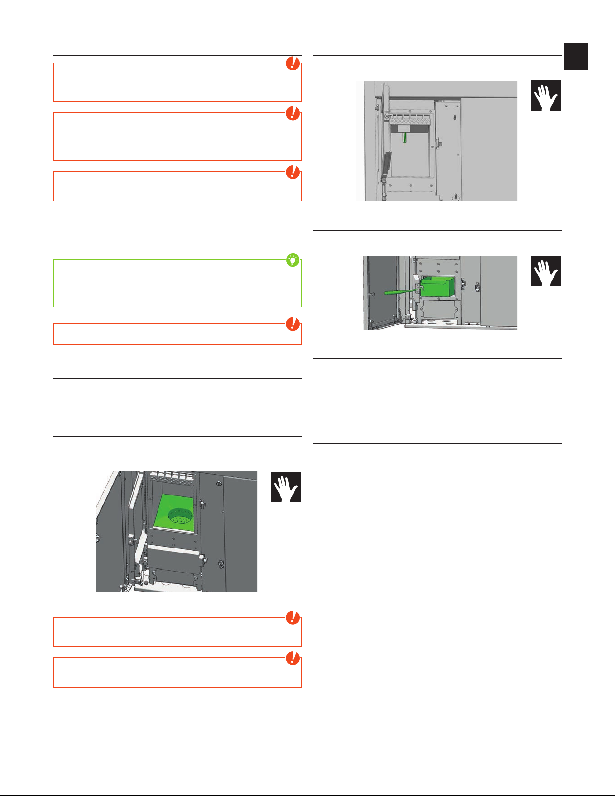
External connection cable bridge
(condition as delivered)
If the control of your stove is to be assumed by an external room thermostat,
you have to connect your external room thermostat (1) instead of the standard
integrated cable bridge (2).
The connected room thermostat can be operated in either MANUAL or
AUTOMATIC MODE. In both MODES, the current set heat output is used, in
AUTOMATIC MODE the heating times set at the stove can also be activated.
You can see whether the external demand is currently activated in the INFO main
menu in submenu item Info - inputs.
If your stove receives an external demand to stop operation, it takes approx. 5
minutes until it switches off. All further settings required to your thermostat can
be taken from the respective room thermostat operating instructions.
Note
Operation is not possible unless either a cable bridge or an external room
thermostat is connected. The external demand has priority over all operating
modes (MANUAL/AUTOMATIC/COMFORT).
Option RIKA firenet
Only for combination and pellet stoves with touch panel version V2.16 or higher.
The RIKA firenet module connects your stove to the Internet. You can operate
the stove with any Internet-enabled device (tablet, PC, Smartphone ...). So you
retrieve the operational status, various information and make your settings
remotely.
For further information, please contact your RIKA dealer.
Page 17
|
17
EN
16
8. CLEANING AND MAINTENANCE
Basic information
Note
Ensure that you do not vacuum into the combustion air line during heating
operation during any cleaning (vacuuming). You could vacuum out embers –
FIRE RISK!
Note
SERVICE appears on the display after consumption of 700 kg pellets. Cleaning
and maintenance is to be performed.
This message can be acknowledged by pressing ENTER and operation can
be continued. The number of SERVICE messages is stored in the background.
Note
Your stove must be switched off and cooled before any maintenance work is
performed. Only work on the unit when the mains plug has been disconnected.
The frequency with which the stove requires cleaning and the maintenance
intervals depend on the fuel you use. High moisture content, ash, dust and chips
may more than double the maintenance required. We would like to again point
out that only tested and recommended pellets or logs may be used as fuel.
Tip
Wood as fertiliser - the mineral content of the wood remains in the combustion
chamber as ash as a residue of the combustion. This is an excellent fertiliser
for all plants in the garden; it is a completely natural product. The ash should
be stored first and slaked with water.
Note
Ash may contain embers – only place ash in sheet steel containers!
Open the combustion chamber door
To open or close the combustion chamber door and the ash-chamber door use
the included key. This key can be stored on the back of the stove when not in
use.
Cleaning the fire trough
Despite the automatic ash dumping prior to and during heating operation, care
should be taken that the air intake openings are not blocked with ash or clinker.
Remove the clinker using the brush supplied and vacuum out the fire trough.
Do not damage the ignition when cleaning with the brush.
Note
Clean the fire trough regularly. Only clean when cold, when embers are
extinguished!
Note
If the stove is heated in continous operation, it must be cleaned 2x within 24
hours. FIRE HAZARD!
Cleaning the flame temperature sensor
Remove the dust deposits from the sensor at regular intervals. Use a clean
cleaning cloth or newspaper.
Empty the ash drawer
Empty the ash drawer regularly. The ash drawer is simply pulled forward with
the ash-chamber door open.
Cleaning the door glass
The viewing window becomes coated in the case of solid fuels, particularly with
the very fine ash of wood pellets, light or dark depending on the pellet quality
(especially with low output). The glass can be cleaned best with a moist cloth.
Stubborn dirt can be removed with a special cleaner available from your stove
dealer. Usual cleaners containing acid or solvents can be too harsh and damage
the glass.
Cleaning painted surfaces
Wipe of the painted surfaces with a damp cloth, do not scrub. Do not use
solvent-containing cleaners.
Page 18
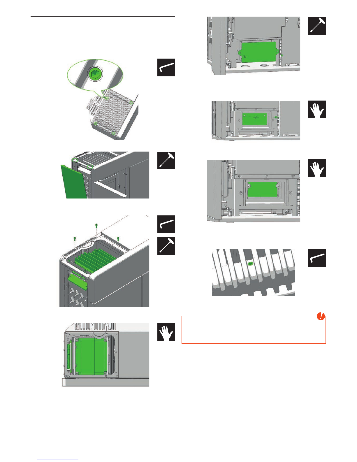
Cleaning flue gas paths
The flue pipes should be cleaned at least 2 x a year or after approx. 700 kg
pellets. The flues are behind the combustion chamber.
Open the decorative glass door by pushing the button on the display before you
unplug the stove from the power supply.
To remove the convection fins turn the 4 screws (marked) clockwise, the lid lifts
off. Then carefully remove the convection fins up.
Now remove the two hex screws on the side panel and lift the side panel.
Loosen the 4 allen screws and remove the combustion chamber lid. Remove
the two hex screws and the side cleaning lid.
Now clean the flues with the supplied brush. Vacuum the combustion residues
with a vacuum cleaner.
Loosen the two hex screws under the ash door and open the outer cleaning lid.
Vacuum-clean the combustion residues off the flue gas collecting duct,
especially the areas to the side flues.
Open the two wing nuts of the rear cleaning lid.
Vacuum the combustion residues from the flue gas collecting duct in the rear
side.
Install the removed parts in reverse order again.
Make sure before mounting the convection fins that the 4 screws (marked in
green) are flush.
Then carefully place the convection fins in the supposed recess and press down
firmly with your hand until the cover locks into place.
Note
Your stove may suck in false air via incorrectly sealed cleaning covers; this
air may lead to incomplete combustion in the fire trough and thus piling up of
pellets - FIRE HAZARD! To ensure the proper operation of your pellet stove,
replace the defect (porous, frayed) seals after cleaning and maintenance.
#2,5
#8
#8
#6
#8
#2,5
Page 19

|
19
EN
18
Cleaning the convection air openings
Vacuum clean any dust deposits from the convection air openings at regular
intervals.
The stove should be cleaned thoroughly prior to the start of the heating season
to prevent excess odour.
Combustion air - intake
If necessary, please also clean the air intake with a hoover.
Note
Only when the stove is cold! You could vacuum out embers – FIRE RISK!
Cleaning the pellet container
Do not refill the completely empty container immediately; remove the residues
(dust, chippings etc.) from the empty container. The unit must be disconnected
from the mains!
Cleaning the flue gas channels
annually
Remove the flue pipes. Inspect and clean chimney connection. Brush off any
soot and dust deposits in the fire and in the flue pipes and vacuum.
Note
Accumulated fly ash in the flue gas channels may impair the performance of
the stove and pose a safety risk.
Checking door seal
annually
The condition of the seals at doors and glass should be checked at least 1 x per
year. Repair or replace seals depending on condition.
Note
Only intact seals ensure your stove works perfectly.
Bearings
annually
All built in bearings (pellet screw, turning grid) should be checked. Clean or
replace bearings depending on condition.
Page 20

9. PROBLEMS - POSSIBLE SOLUTIONS
Problem 1
Fire burns with weak, orange flame. Pellets heap up in fire trough, window
sooted up.
Cause(s)
Q Insufficient combustion air
Q Poor chimney draught
Q Stove is sooted over inside
Possible solutions
Q Remove any ash or clinker from the fire trough that may block the air inlets.
If possible swap to better pellet quality (see CLEANING AND MAINTENANCE)
Q Check whether flue gas pipes are blocked with ash (see CLEANING AND
MAINTENANCE).
Q Check whether the suction nozzles and air inlet pipe or flue tube are blocked.
Q Check door and cleaning cover seals for leaks (see CLEANING AND
MAINTENANCE)
Q Clean blower impeller (see CLEANING AND MAINTENANCE)
Q Have service performed by authorised specialist company.
Problem 2
Stove smells strongly and smokes outside.
Cause(s)
Q Burning-in phase (taking into service)
Q Stove has accumulated dust and/or dirt
Possible solutions
Q Wait to end of burning-in phase and vent sufficiently
Q Suction off any dust deposits from the convection air openings at regular
intervals
Problem 3
Flue gas discharge when wood is added and during heating phase.
Cause(s)
Q Inspection openings leak
Q Chimney draught too low
Q Flue pipe connection leaks
Possible solutions
Q Check seals and replace (fire door, plaster cover, ..)
Q Check chimney
Q Check connections and if necessary re-seal
Note
Please note that checks on the control system and wiring ma only be
performed in unit switched dead. Any repairs may only be performed by
trained specialists.
Tip
If a malfunction message occurs, the cause must first be remedied; the
unit can be put back into operation by acknowledging the malfunction at the
internal unit.
Page 21

|
21
EN
20
10. INSTRUCTIONS FOR COMMISSIONING PROTOCOL
FOR PELLET AND COMBI STOVES
The commissioning protocol is to be treated as a documents and serves as
the basis for the warranty and guarantee terms. It is to be completed entirely,
in particular the stove data and addresses, the work to be performed is to be
ticked off after completion. The signatories confirm with their signatures that all
the items on the list have been concluded properly.
Note
Please return 1 completed protocol for putting into service to
RIKA Innovative Ofentechnik GmbH, Müllerviertel 20, 4563 Micheldorf, Austria.
Electrical periphery
It is important that the connection socket in the electrical periphery is earthed.
The operability of any room thermostat present must be checked. The execution
of commands is to be established by phoning in the case of a GSM modem.
Exhaust gas system
The exhaust line, stove and combustion air inlet are part of the combustion
system as a whole; therefore the correct execution must also be checked.
The plug connections should be tight in general since the system works with
excess pressure. The exhaust tube has a diameter of 100mm for pellet stove,
and of 150 mm for the combi stove, which is sufficient for short distances. In
the case of several changes in direction, the resistance of the exhaust system
can increase with the flue to such an extent that the combustion quality suffers
and/or noise arises from the greater flow speed. Correct determination of the
chimney draught can only be performed at nominal thermal output and serves
to evaluate the chimney. If the draught is more than 15 Pa, then a draught
limiter should be installed.
Stove functions
These are the basic stove functions that are to be checked and ticked off. The
stove is ready for operation if these functions are ensured.
Operator instruction
This is one of the most important points in the putting into operation. It is very
important that the operator understands the stove properly and is prepared to
assume responsibility for the basic tasks required for operational safety.
In particular the connection between special features of a biomass heating
system and his obligations as well as the warranty and guarantee terms must
be explained. e.g. non-tested pellets and screw blockers, lack of cleaning or
maintenance and stove malfunctions. Thorough instruction can prevent many
complaints.
Stove functions
Explanation of the processes in the stove during ignition, normal operation,
cleaning phase etc.
Control
Explain operator’s possibilities to intervene, empty pellet container, room
thermostat, GSM modem, functions and settings, program times if necessary.
Operating instructions: Handover and reference to the content to the following
points, is a document.
Warranty terms
Difference between warranty (statutory) and guarantee (voluntary), terms of
guarantee, determination of wearing parts, reference to pellet quality to be
used and the consequences of poor quality.
Cleaning instructions
Ash and dust occurs with a biomass heating unit. The fire trough is to be
cleaned regularly with regular heating operation (in the case of pellet operation,
the drilled air holes in particular must be free of residues). The ash drawer is
to be emptied regularly. The flue gas pipes are to be cleaned once or twice in
the heating season depending on stove type; by a specialist company is best.
Maintenance
Maintenance work after defined burn-off output is to be performed by specialist
company, including thorough cleaning.
Combustion
All doors must close tightly to prevent intake of false air.
Page 22
Note
Please contact your warranty partner for any warranty questions or claims. This is your dealer or installation company. No warranty claims can be accepted
without proper putting into operation, proper operation according to the operating instructions and the supplements in this information sheet.
Protocol for putting into operation for RIKA pellet and combi stoves Date:____________________
Installation address
Name:_________________________________________
Street:_________________________________________
City:___________________________________________
Telephone:______________________________________
Dealer
Name:_________________________________________
Street:_________________________________________
City:___________________________________________
Telephone:______________________________________
Stove data
Stove type: Casing undamaged
Serial number: Operating instructions
Software version: Warranty documents
Touchdisplay version: Door opener
Electrical periphery
Connection socket earthed GSM modem present
Room thermostat present Function checked
Check of system components
Combustion chamber door seal checked Ease of movement burnback flap checked (combi)
Ease of movement flue gas flap checked (combi)
Exhaust line / chimney
Diameter Connection leakproof
Bends Chimney draught
Stove functions
Pellet container filled Grid turns (360°) und keeps in heating position
Tested pellet quality according to Önorm/DIN plus/
ENplus-A1
Ignition element glows
Electrical connections made Screw motors run
Safety flaps tightened (combi) Do pellets fall into the combustion chamber?
Induced draught blower runs Ignition performed
Stove was switched off when handed over
Operator instruction
Stove function Warranty terms
Control Cleaning
Operating instructions Cleaning or maintenance interval
work performed correctly according to order placed
_______________________ _____________________ _______________________
Technican: Operator Client
Company:_______________________________________
Page 23

|
23
EN
22
11. GUARANTEE
These warranty conditions are only valid for the following countries: Austria, Germany and Switzerland. Separate conditions imposed by the importer apply for all
other countries. In case of doubt as well as missing or incorrect translations, the German version is the only valid one.
For the purpose of timely damage limitation, the warranty claim on the part of the claimant is to be enforced at the RIKA dealer in writing using the invoice and
stating the purchase date, model name, serial number and reason for complaint.
WARRANTY
5 years on the welded stove body. This exclusively applies to defects in materials and workmanship as well as free replacement. Labour and travel times are not
included in the manufacturer’s warranty.
Only original parts supplied by the manufacturer should be used. Loss of warranty on non-observance!
The precondition for the warranty is that the stove has been installed and commissioned properly according to the User and installation manuals valid at the time
of purchase. Connection must be performed by a specialist for such stoves.
Any costs incurred by the manufacturer due to unjustified warranty claims are to be charged to the claimant.
Wear parts and parts affected by fire are excluded, such as glass, coating, surface coatings (e.g. handles, panels), seals, fire trough, grates,
draught plates, deflector plates, combustion chamber liners (e.g. fireclay), ceramics, natural stone, thermo stone, ignition elements, sensors,
combustion chamber sensors and temperature controller.
Damage arising from non-observance of the manufacturer’s instructions for operation of the unit or any damage that is caused by action such as overheating, use
of non-approved fuels, tampering with the device or the flue gas pipe, electrical excess voltage, an incorrect, insufficient or excessive flue draught, condensation,
non-performance or deficient maintenance and cleaning, non-observance of the relevant and applicable building regulations, incorrect operation by the user or
third parties, transport and handling damage is also excluded.
THE WARRANTY DOES NOT AFFECT THE STATUTORY WARRANTY PROVISIONS.
02.12.2015
Page 24

RIKA Innovative Ofentechnik GmbH
4563 Micheldorf / Austria, Müllerviertel 20
Telefon: +43 7582 686 - 41, Fax-DW: 43
E-Mail: [email protected]
RIKA.AT
Technical and design changes, as well as typesetting and printing errors reserved
© 2015 | RIKA Innovative Ofentechnik GmbH
Z35979_EN_Domo | 8.02.2016
 Loading...