

Page 1
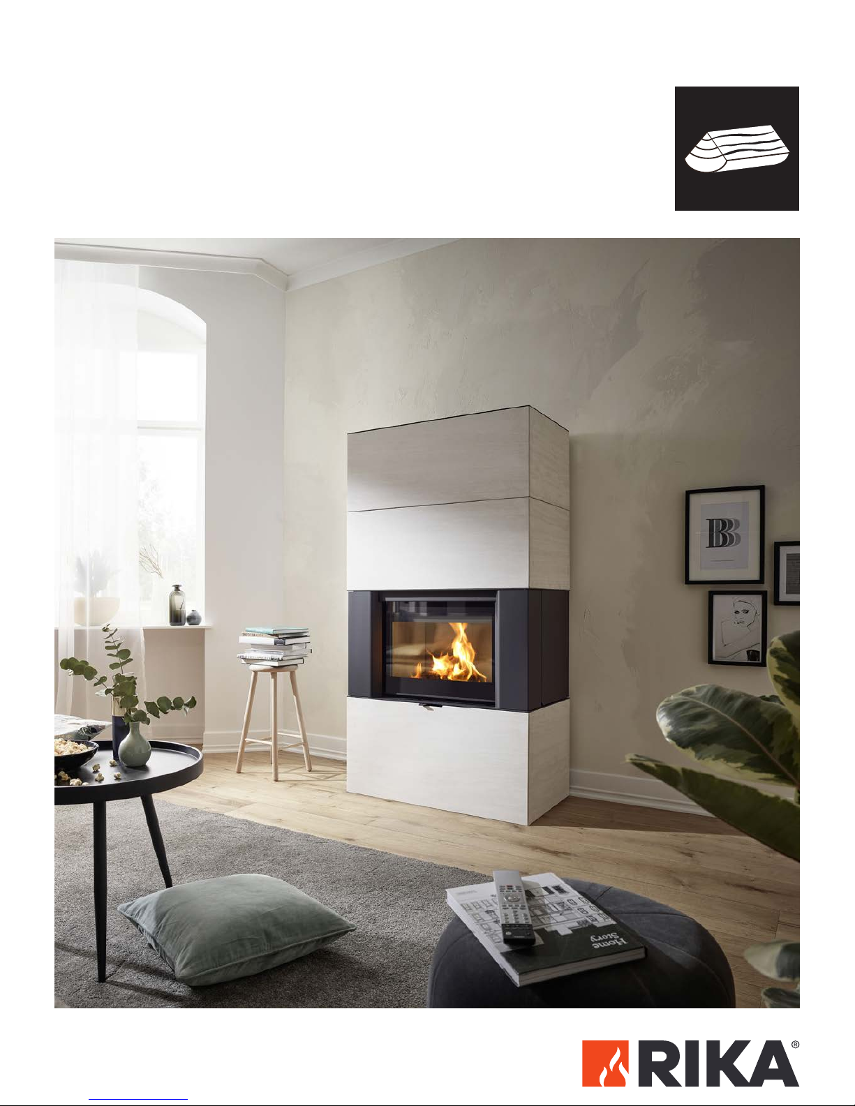
Operating manual
AMBIA
Page 2

TABLE OF CONTENTS
1. PREFACE 3
Explanations to symbols �������������������������������������������������������������������������������������������������������������������������������������������������������������������������������������������������� 3
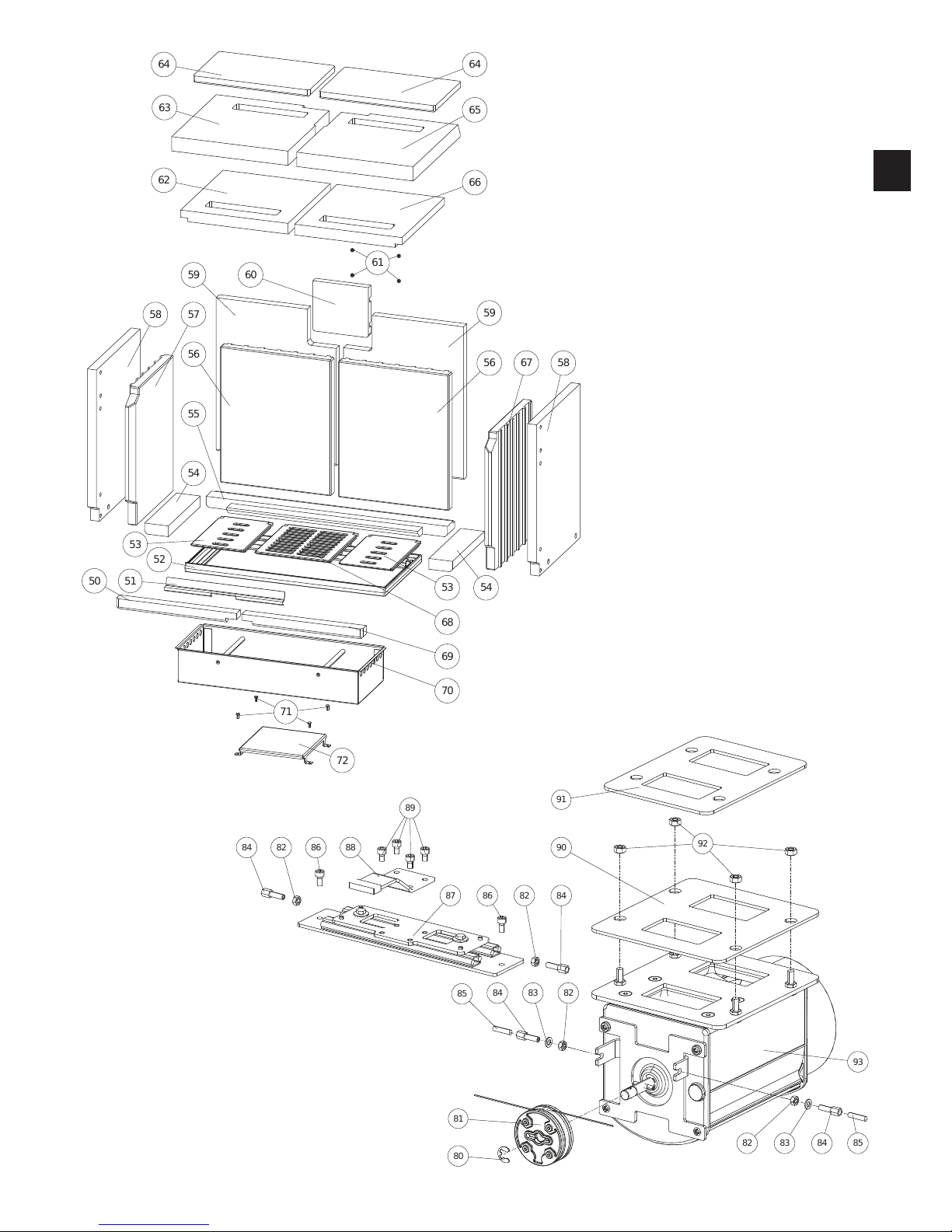
Spare part overview exploded diagram ������������������������������������������������������������������������������������������������������������������������������������������������������������ 4
Steelshell ����������������������������������������������������������������������������������������������������������������������������������������������������������������������������������������������������������������������������������������� 6
Stone casing �������������������������������������������������������������������������������������������������������������������������������������������������������������������������������������������������������������������������������� 8
Spare part overview article numbers �����������������������������������������������������������������������������������������������������������������������������������������������������������������10
Dimensions
�����������������������������������������������������������������������������������������������������������������������������������������������������������������������������������������������������������������������������������11
Amount of fuel ���������������������������������������������������������������������������������������������������������������������������������������������������������������������������������������������������������������������������11
Technical data ���������������������������������������������������������������������������������������������������������������������������������������������������������������������������������������������������������������������������11
Packaging
��������������������������������������������������������������������������������������������������������������������������������������������������������������������������������������������������������������������������������������11
2. INSTALLING THE STOVE 12
General information ������������������������������������������������������������������������������������������������������������������������������������������������������������������������������������������������������������12
Connection to the chimney ������������������������������������������������������������������������������������������������������������������������������������������������������������������������������������������12
Connecting to a steel chimney
���������������������������������������������������������������������������������������������������������������������������������������������������������������������������������12
Combustion air
������������������������������������������������������������������������������������������������������������������������������������������������������������������������������������������������������������������������12
Feeding in external combustion air ����������������������������������������������������������������������������������������������������������������������������������������������������������������������12
3. BRIEF INFORMATION ON COMBUSTIBLE - LOGS 13
Suitable fuels and fuel amounts ����������������������������������������������������������������������������������������������������������������������������������������������������������������������������� 13
Wood types
��������������������������������������������������������������������������������������������������������������������������������������������������������������������������������������������������������������������������������� 13
Output controlling ���������������������������������������������������������������������������������������������������������������������������������������������������������������������������������������������������������������� 13
Clean combustion ���������������������������������������������������������������������������������������������������������������������������������������������������������������������������������������������������������������� 13
4. IMPORTANT INFORMATION 14
General warning and safety information ������������������������������������������������������������������������������������������������������������������������������������������������������� 14
First heating �������������������������������������������������������������������������������������������������������������������������������������������������������������������������������������������������������������������������������14
Safety distances �������������������������������������������������������������������������������������������������������������������������������������������������������������������������������������������������������������������� 14
Prior to set up ����������������������������������������������������������������������������������������������������������������������������������������������������������������������������������������������������������������������������15
5. MANUAL OPERATION 16
Combustion air regulation ������������������������������������������������������������������������������������������������������������������������������������������������������������������������������������������� 16
RIKA firelighter ������������������������������������������������������������������������������������������������������������������������������������������������������������������������������������������������������������������������� 16
Correct heating up ���������������������������������������������������������������������������������������������������������������������������������������������������������������������������������������������������������������17
Page 3

|3
EN
2
1. PREFACE
Explanations to symbols
...Important
Note
...Useful
Tip
...Manually
6. CLEANING AND MAINTENANCE 18
Basic information ����������������������������������������������������������������������������������������������������������������������������������������������������������������������������������������������������������������� 18
Cleaning the combustion chamber ��������������������������������������������������������������������������������������������������������������������������������������������������������������������� 18
Empty the ash drawer ������������������������������������������������������������������������������������������������������������������������������������������������������������������������������������������������������ 18
Cleaning painted surfaces ������������������������������������������������������������������������������������������������������������������������������������������������������������������������������������������� 18
Cleaning the convection air openings �������������������������������������������������������������������������������������������������������������������������������������������������������������� 18
Cleaning the flue pipes
��������������������������������������������������������������������������������������������������������������������������������������������������������������������������������������������������� 19
Checking door seal ������������������������������������������������������������������������������������������������������������������������������������������������������������������������������������������������������������ 20
7. PROBLEMS - POSSIBLE SOLUTIONS 21
Problem 1 ����������������������������������������������������������������������������������������������������������������������������������������������������������������������������������������������������������������������������������������21
Problem 2 ���������������������������������������������������������������������������������������������������������������������������������������������������������������������������������������������������������������������������������������21
Problem 3 ��������������������������������������������������������������������������������������������������������������������������������������������������������������������������������������������������������������������������������������21
8. WARRANTY 22
Your notes ����������������������������������������������������������������������������������������������������������������������������������������������������������������������������������������������������������������������������������� 23
Page 4
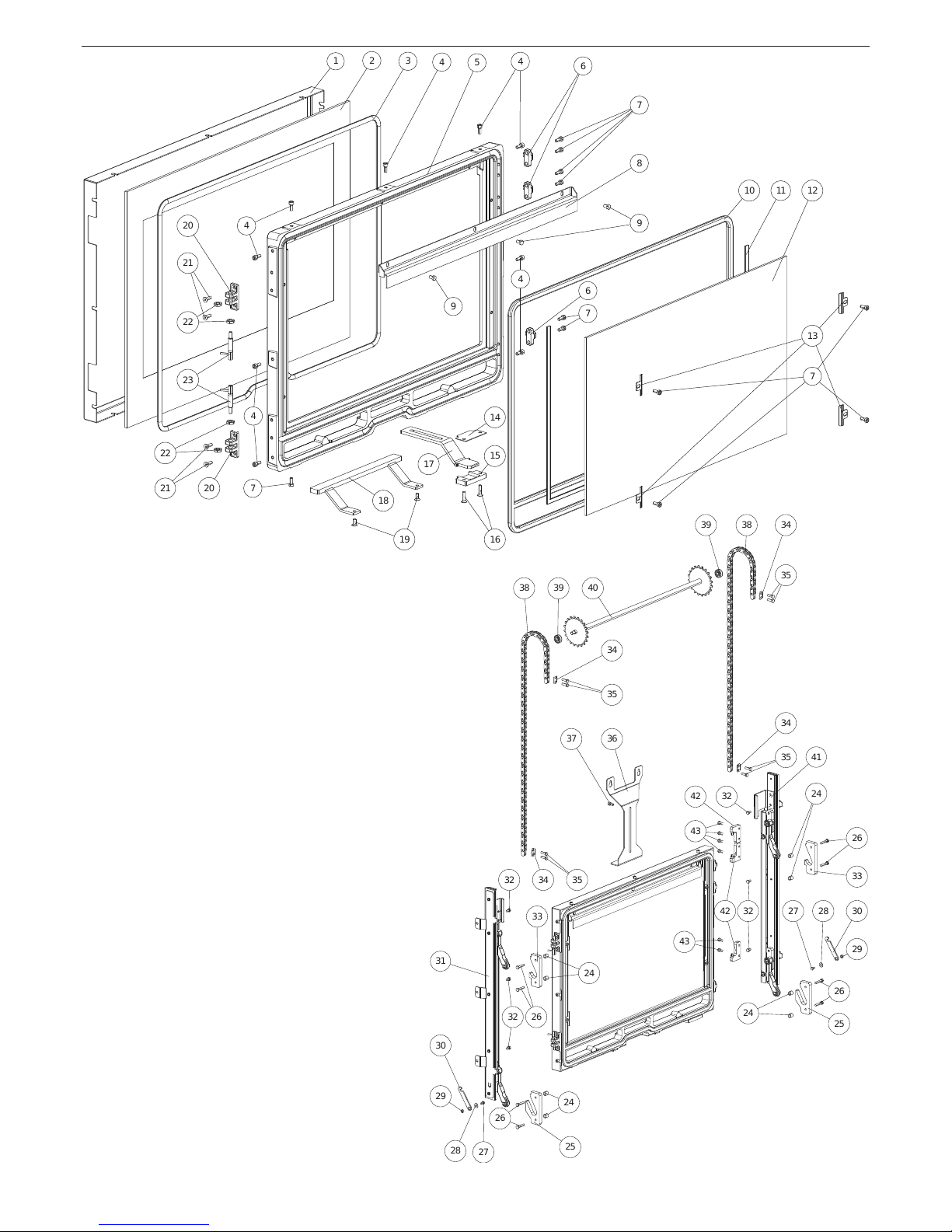
Spare part overview exploded diagram
51012
11
13
7
321
7
4
444
4
6
6
7
7
20
20
21
21
23
22
22
18
19
8
9
9
14
15
16
17
3940393736
31
25
33
24
24
26
26
32
32
26
41
323242
43
43
42
25
33
24
24
26
302928
27
30
29
28
27
38
38
34
34
35
35
34
34
35
35
Page 5
69
50
55
54
54
61
646465
63
59
59
58586056566662
67
57
52
72
71
70
53
53
68
51
91
90
93
81
84
848083
83
82
82
92
85
85
87
88
89
8686848482
82
|5
EN
4
Page 6
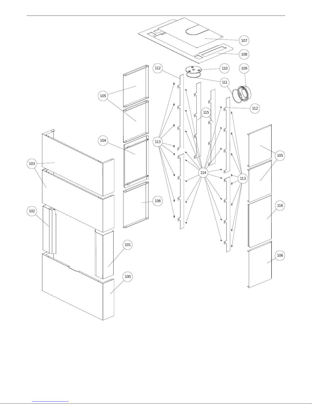
Steelshell
109
110
111
116
104
112
112
115
113
113
114
101
102
100
106
106
103
105
105
108
107
Page 7
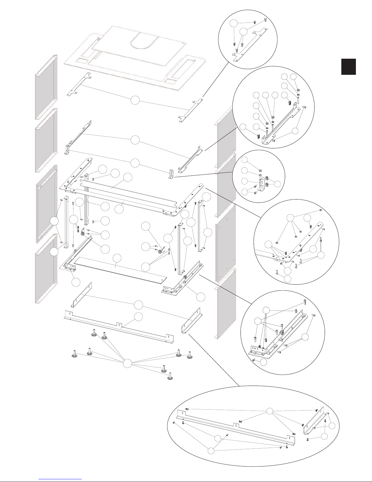
132
129
117
124
118
118
123
123
120
120
120
120
120
119
119
119
119
119
122
122
120
119
119
125
130
131
126
127
128
121
120
120
119
135
135
135
136
136
136
137
137
137
133
134
120
119
135
136
137
120
120
119
119
138
138
137
120
119
119
139
120
119
119
133
133
|7
EN
6
Page 8
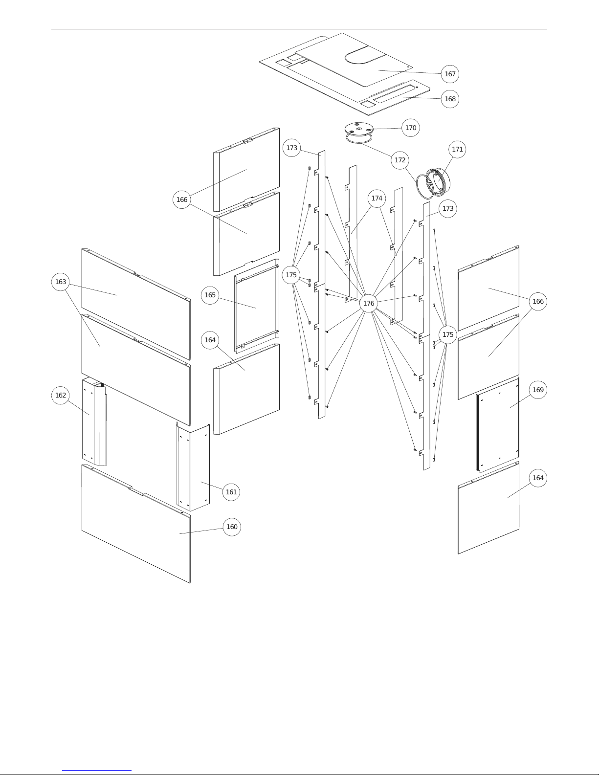
Stone casing
171
170
172
173
173
174
175
175
176
161
162
169
165
166
163
166
160
164
164
168
167
Page 9
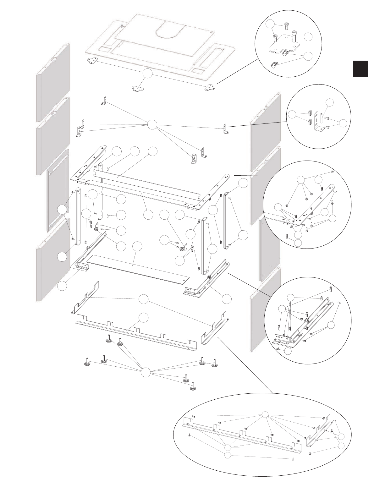
132
178
180
179
177
129
117
124
118
118
123
123
120
120
120
120
120
119
119
119
119
119
122
122
120
119
119
125
121
120
181
138
120
120
119
119
138
138
137
120
119
119
139
133
133
120
181
181
120
181
182
|9
EN
8
Page 10

Nr. Art.Nr. Description
1 Z37874 Door frame
B18563
Combustion chamber door
assy
2 Z37059 Decorative glass
3 N112616 Round hollow seal Ø10
4 N112169 Hexagon socket screw
5 Z37644 Combusion chamber door
6 Z37621 Retaining plate
7 N111910 Allen screw
8 L03696 Panel secondary air
9 N111964 Hexagonal screw
10 N112614
Round sealing strip grey
D13
11 N103693 Flat seal black 8x2
12 Z37060 Front door glass
13 L00475 Glass holder
14 L03601 Closure plate
15 L03602 Closure flap
16 N110586
Hexagonal countersunk
screw
17 L03603 Handle Cold Hands
18 LB00766 Door opener
19 N112382
Hexagonal countersunk
screw
20 Z37897 Angle support
21 N112438
Hexagonal countersunk
screw
22 N105378 Hexagonal nut
23 N112522 Locking pin
24 Z28059 Spacer
25 L03589 Bottom guidance
26 N112051 Hexagonal screw
27 N112415 Hexagonal screw
28 N112269 Washer
29 Z38225 Spacer
30 L03588 Lock for telescopic rail
31 B18561 Telescopic rail right
32 N111964 Hexagonal screw
33 L03590 Top guidance
34 L03695 Washer
35 N112140 Hexagonal screw
36 L03616 Lock for chain
37 N108486 Allen screw
38 N112526 Chain
39 N111747 Ball bearing
40 B18566 Gear shaft
41 B18562 Telescopic rail
42
L03599 Hinge plate
43 N109718 Allen screw
50 Z37860
Bottom firebrick lining, front
left
51 Z37862 Wood retainer
52 Z37641 Bottom plate
53 Z37642 Grate laterally
54 Z37072
Bottom firebrick lining
laterally
55 Z37071 Bottom firebrick lining rear
56 Z37805 Firebrick lining rear
57 Z37803 Firebrick lining left
58 Z37825 Firebrick lining lateral
59 Z37824 Firebrick lining rear
60 Z37861 Firebrick lining rear middle
Nr. Art.Nr. Description
61 N112274 Hexagonal nut
62 Z37827 Firebrick lining cover left
63 Z37823 Firebrick lining cover left
64 Z37821 Firebrick lining cover
65 Z37822 Firebrick lining cover right
66 Z37826 Firebrick lining cover right
67 Z37804 Firebrick lining right
68 Z37643 Grate middle
69 Z37070
Bottom firebrick lining, front
right
70 LB00765 Ash drawer
71 N111950 Hexagonal screw M05x10
72 L03582 Cover
80 N104718 Circlips
81 B18557 Pulley with steel cable
82 N106175 Hexagonal nut
83 N111965 Washer M05
84 N112476 Adjusting screw
85 N112475 Bowden cable housing
86 N108486 Allen screw
87 B18558 Regulator assy
88 LB00764 Regulator handle
89 N111948 Hexagon socket screw
90 Z37407 Seal
91 Z37408 Seal
92 N103988 Hexagonal nut M06
93 B18556
Airbox with intake pipe
socket
B18555 Airbox assy
100 LB00744 Bottom steel front
101 B18578 Cover left
102 B18579 Cover right
103 LB00746 Top steel front
104 B18581 Side casing steel, left
105 LB00747 Side casing steel, top
106 LB00745 Side casing steel, bottom
107 L03631 Lid
108 LB00775 Cover frame
109 Z20556
Flue pipe connection black
150mm
110 Z37039 Blind cover black
111 N103066
Round sealing strip black
D06
112 Z37884 Cover panel rear
113 N112540 Sliding block
114 N112169 Hexagon socket screw
115 Z37892
Cover panel rear middle
116 B18580 Side casing steel, right
117 B18661 Side cover bracket left
118 Z37886 Hinge stop angle
119 N112169 Hexagon socket screw
120 N112540 Sliding block
121 Z38178 Glass cover
122 B18577 Magnet
123 Z37887 Hinge stop angle
124 B18576 Side cover bracket
125 L03626 Cover panel, top
126 L03629 Angle support
127 Z37895 Side cover bracket
128 Z37896 Side cover bracket cover
129 B18660 Side cover bracket right
Nr. Art.Nr. Description
130 Z37894 Side cover bracket bottom
131 Z37893 Front cover bracket bottom
132 N112490 Levelling screw black
133 N112008 Hexagonal screw
134 N112240 Self-tapping screw
135 N112253 Grub screw
136 N107499 Hexagonal nut
137 N111933 Flange nut
138 N108573 Hexagon socket screw
139 N112266 Cylinder screw
160 Z37747 Soapstone front, bottom
Z37748 White stone front, bottom
Z37790
Concrete front stone,
bottom
161 B18578 Cover left
162 B18579 Cover right
163 Z37753 Soapstone front, top
Z37754 White stone front, top
Z37793 Concrete front stone, top
164 Z37749
Side panel soap stone,
bottom
Z37750
Side panel white stone,
bottom
Z37791 Side panel concrete, bottom
165 B18581 Side casing steel, left
166 Z37755 Side panel soap stone, top
Z37756 Side panel white stone, top
Z37794 Side panel concrete, top
167 L03631 Lid
168 LB00775 Cover frame
169 B18580 Side casing steel, right
170 Z37039 Blind cover black
171 Z20556
Flue pipe connection black
150mm
172 N103066
Round sealing strip black
D06
173 Z37884 Cover panel rear
174 Z37892 Cover panel rear middle
175 N112540 Sliding block
176 N112169 Hexagon socket screw
177 L03629 Angle support
178 L03630 Stone retainer
179 Z37890
Angle support bottom,
lateral
180 Z37889
Angle support bottom,
frontal
181 N112243 Hexagon socket screw
182 N108573 Hexagon socket screw
Spare part overview article numbers
Note: Please consider the powdercoated parts can differ slightly in colour and colour effects though they are elaborated in high quality�
Page 11
|11
EN
10
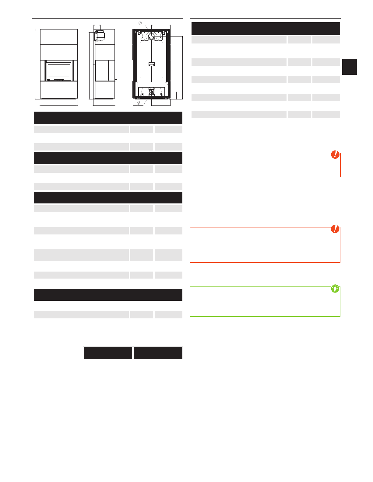
Dimensions
B
H
T
RO-H
F-S
F-H
R-H
R-S/RO-SRO-T3
F-
R-
Dimensions
Height [mm]
Width [mm]
Corpus depth [mm]
Weight
Weight with steelshell [kg]
Weight with stones [kg]
Weight with concrete chemise [kg]
Flue pipe connection
R - Ø Flue pipe outlet [mm]
RO - H original angle pipe connection
height
[cm]
RO - T1 original angle pipe total depth [cm] -
RO - T2 original angle pipe distance to
rear wall
[cm] -
RO - T3 Deapth from rear wall to middle
of flue pipe
[cm]
RO - S original angle pipe side distance [cm]
R - H Rear connection height [cm]
R - S Rear connection side distance [cm]
Fresh air connection
F - Ø Diameter [mm]
F - H Connection height [cm]
F - S Side distance [cm]
Amount of fuel
Nominal load Part load
Amount of fuel ~, kg* ~, kg*
*Practical values may vary depending on fuel quality�
Technical data
Technical data
Heating power range [kW] -
Room heating capacity (depending on
house insulation)
[m
] -
Fuel consumption [kg/h] to ,
Efficiency [%] %
CO
2
[%] testing
CO-emission on 13% O
2
[mg/m
N
]
Dust emission [mg/m
N
]
Exhaust [g/s] testing
Exhaust temperature [°C] testing
Chimney draft requirement [Pa]
The owner of small firing systems or the person authorised for the
small firing system is to keep the technical documentation and is to
submit it to the authorities or the chimney sweep on request�
Note
Please observe the national and European standards as well as
local regulations concerning the installation and operation of
firing installations!
Packaging
Your first impression is important to us!
The packaging of your new stove provides excellent protection
against damage� However damage to the stove and accessories
may still occur during transport�
Note
Therefore please check your stove on receipt for damage and
completeness! Report any deficiencies to your dealer immediately!
Pay particular attention during unpacking that the stone panels
remain intact� Scratches to the material can easily occur� Stone
panels are excluded from the warrant�
The packaging of your new stove is environmentally neutral to a
great extent�
Tip
The wood used in the packaging has not been surface treated
and may therefore be burnt in your woodburning stove (not in a
pelletstove!)� The cardboard and film (PE) can be depolluted via
the municipal waste collection for recycling�
Page 12
2. INSTALLING THE STOVE
General information
Note
Assembly may only be performed by authorised specialist
companies�
Note
Please observe the regional safety and building regulations� Please
contact your master chimney sweep in this context�
Note
Only use heat-resistant sealing materials as well as corresponding
sealing strips, heat-resistant silicon and rock wool�
Note
Also take care that the flue does not project into the free crosssection of the chimney�
Note
In case of room-air independent operation the stove pipe
connections must be tightly sealed permanently� Use a heat-proof
silicon to position the stove pipe on the conical supports of the flue
tube nozzles and for insertion in the chimney flue lining�
Note
The stove should not be pushed on unprotected floors�
Tip
Strong corrugated cardboard, cardboard or e�g� old carpet is useful
to assist assembly and as a base� The stove can also be pushed on
this cardboard or carpet�
We recommend original flue pipes from RIKA for proper connection�
Connection to the chimney
Q The device must be connected to an approved
chimney for solid fuels� The chimney must have
a diameter of min� 100mm for pellet stoves and
130mm -150mm for log wood stoves depending on the diameter
of the flue pipes�
Q Avoid long flue pipes to the chimney� The horizontal length of the
flue pipe should not exceed 1�5 m�
Q Avoid to many bends of the flue gas pipes� There should not be
more than 3 bends in the exhaust pipe�
Q If you just can not connect directly to the chimney, please use a
connection with a cleaning opening�
Q Connections must be made of metal and must meet the
requirements of the standard (install the connections airtight)�
Q Before installing a chimney calculation must be made� The
evidence must be performed for single occupancy to EN13384-1
and EN13384-2 for multiple occupancy�
Q The maximum draft of the chimney should not exceed 15Pa�
Q The derivation of the flue gases must be guaranteed even during
a temporary power outage�
Note
If connecting to multiple connection chimneys additional safety
equipment is required� Your local chimney sweep will advise you
in this case�
Note
Be sure to prevent condensed water from entering via the flue
connection� You may need to have a condensate ring installed ask your chimney sweeping expert for more information� Damages
caused by condensate are excluded from manufacturer’s warranty�
Connecting to a steel chimney
The connection must be calculated and shown with EN13384-1
and EN13384-2�
Use only insulated (double) stainless steel tubes (flexible aluminum
or steel tubes are not permitted)�
An inspection door for regular inspection and cleaning must be
present�
The flue pipe connection to the chimney has to be air-tight�
Combustion air
Every combustion process requires oxygen from the surrounding air�
This so-called combustion air is removed from the living are in the
case of individual stoves without external air connections�
This air removed must be replaced in the living space� Very tightly
sealed windows and doors in modern flats may mean that too little
air replaces that used� The situation also becomes problematical due
to additional venting in flats (e�g� in the kitchen or WC)� If you cannot
feed in external combustion air, then air the room several times a
day to prevent negativce pressure in the room or poor combustion�
Feeding in external combustion air
only for devices which are able to run in room-air independent
operation�
Q Combustion air must be fed to the stove from outside via a sealed
pipe for operation independent of the room air� According to
EnEV, it must be possible to shut off the combustion air pipe� The
open/closed setting must be clearly recognisable�
Q Connect at the air intake either a pipe Ø125mm (log wood and
combi stoves) or Ø50mm (pellet stoves) and fix it with a hose
clamp (not included!)� At pellet stoves with longer intake pipes
than 1m the diameter should be increased to 100mm� (see RIKA
range)�
Q To ensure sufficient air intake, the intake pipe should not exceed
max� 4m and have max� 3 bends�
Q If the line leads outside it must have a windbreak�
Q In extreme cold pay attention to icing on the air intake opening
(check)�
Q It is also possible to suction in combustion air directly from
another sufficiently vented room (e�g� cellar)�
Q The combustion air pipe must be tightly connected (adhesive or
cement) permanently to the air nozzles of the stove�
Q If you do not use the stove for a long time, please close the
combustion air intake to prevent the stove from moisture�
Note
Please note that problems may arise due to updrafts in the case
of combustion air supply from an integrated chimney ventilation
shaft� If the combustion air flowing downwards is heated it may
rise and thus counter the chimney with a resistance which in turn
reduces the negative pressure in the combustion chamber� The
chimney manufacturer is to guarantee that the resistance for the
combustion air is a maximum 2 Pa even in the least favourable
operating state of the chimney�
If one or more of these conditions does NOT apply, the result is poor
combustion in the stove and negative pressure in the installation
room�
Page 13

|13
EN
12
3. BRIEF INFORMATION ON COMBUSTIBLE - LOGS
Suitable fuels and fuel amounts
Your stove is generally suitable for burning dry firewood� You can
also burn combustibles such as wood briquettes�
Note
A stove is not a waste incinerator� The warranty lapses if waste or
non-approved materials such as plastic, treated wood (chipboard),
coals or clothes are burnt! This leads to damage to the stove and
chimney and to environmental pollution!
Note
FUEL AMOUNTS
The stove is fitted with a construction-specific flat firebox� This
means only one layer of logs may be laid on the base embers�
Please observe that adding greater quantities of logs leads to
emission of high temperatures, higher than the stove is designed
for� This may cause damage to your stove� This is reflected in
particular on the glass of the combustion chamber door, which will
get a gray haze in case of overheating the stove, which can not be
removed�
Wood types
Different types of wood have different calorific values� Wood from
deciduous trees is particularly suitable� It burns with a constant
flame and forms long-lasting embers� Coniferous wood has higher
levels of resin and burns off faster as do all softwoods and tends to
spray sparks�
Wood type
Calorific
value
kWh/m
3
Calorific
value
kWh/kg
Maple ,
Birch ,
Beech ,
Oak ,
Alder ,
Ash ,
Spruce ,
Larch ,
Poplar ,
Robinia ,
Fir ,
Elm ,
Willow ,
Output controlling
The output of your stove is regulated manually or via the Rikatroniccontrol� Please observe that the output of your stove also depends
on the chimney draught and the amount of fuel added�
Clean combustion
1. The firewood must be dry and untreated.
The should-be value is between 14% and 18% relative wood moisture�
Wood has to be stored dry and ventilated for 2 – 3 years�
2. Correct firewood amount and size:
Q Too much firewood leads to overheating� This can damage your
stove and increases the exhaust emission values�
Q If you take too little firewood or if the logs you place are too large
the stove will not reach the optimum operating temperature� The
flue gas values also increase in this case�
Q For right quantity of firewood see AMOUNT OF FUEL.
Page 14
4. IMPORTANT INFORMATION
General warning and safety information
Observance of the introductory general warning information is
imperative�
Q Read the entire manual thoroughly before installing and putting
the stove into service� Observe the national provisions and laws
as well as the regulations and rules applicable locally�
Q RIKA stoves should only be installed in rooms with normal humidity
(dry areas according to VDE 0100 Part 200)� The furnaces are not
splash water protected and may not be installed in wet areas�
Q Only approved transport equipment with sufficient load carrying
capacity may be used with your heating appliance�
Q Your heating appliance is not suitable for use as a ladder or
stationary scaffolding�
Q The burning of fuel releases heat energy that lead to extensive
heating of the stove surfaces, doors, door and operating handles,
glass, flue pipes and possibly the front wall� Refrain from touching
these parts without appropriate protective clothing or equipment
e�g� heat-resistant gloves or means of operation (operating
handle)�
Q Make your children aware of this particular danger and keep
them away from the stove during heating�
Q Only burn approved heating materials�
Q The combustion or introduction of highly flammable or explosive
materials such as empty spray cans etc� in the combustion
chamber and storing them near the stove is strictly prohibited
due to the danger of explosion�
Q No light or inflammable clothing is to be worn when post-heating�
Q Use the heat-resistant gloves supplied to open the doors of your
stove�
Q Only use suitable tools from our range of accessories when
handling embers and make sure that no embers fall out of the
combustion chamber onto inflammable material�
Q Push the embers together to form a firebed when you add new
fuel (logs)�
Q Placing non-heat resistant objects on the stove or near it is
prohibited�
Q Do not place clothing on the stove to dry�
Q Laundry racks etc� must be placed at a sufficient distance to the
stove – ACUTE DANGER OF FIRE!
Q When your stove is burning, the use of highly inflammable and
explosive materials in the same or adjacent rooms is prohibited�
Note
Waste and liquids may not be burnt in the stove!
Note
To prevent your stove from overheating of the internal components,
do never cover the convection fins!
Note
Your stove will expand and contract during the heating and cooling
phase� This can sometimes lead to slight bending or cracking
noises� This is normal and is no reason for a complaint�
First heating
The stove body, just as various steel parts, cast iron parts and the
flue pipes are painted with a heat resistant paint� During the first
heating the paint dries out completely� This may cause a slight smell�
Touching or cleaning the painted surfaces during the curing should
be avoided� The hardening of the paint is finished after the first
heating with high power�
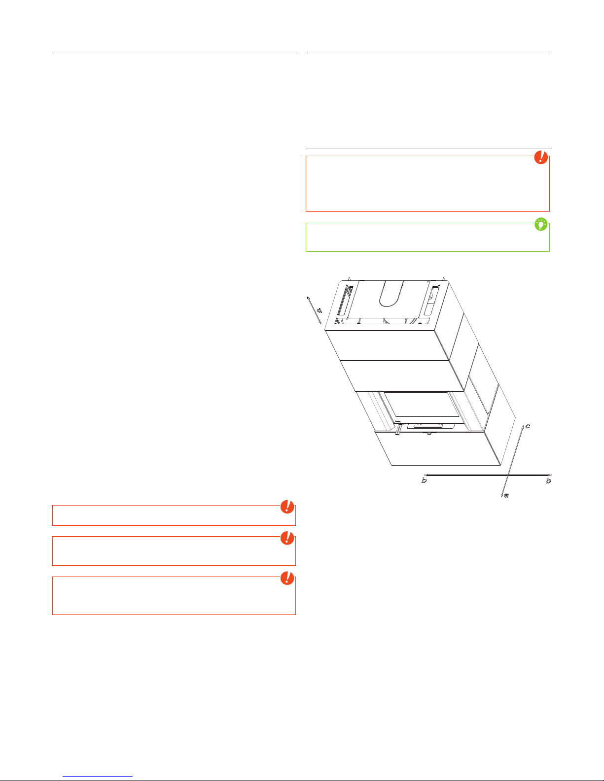
Safety distances
Note
1� To non-combustible objects
a > 40 cm, b > 10 cm, c > 0 cm, d > 50 cm
2� To combustible objects and reinforced concrete load-bearing
walls
a > 80 cm, b > 10 cm, c > 0 cm, d > 50 cm
Tip
Please observe a minimum distance of 20 cm sideways the stove
for maintenance�
Page 15

|15
EN
14
Prior to set up
Floor bearing capacity
Ensure that the substructure is capable of bearing the weight of the
stove prior to set-up�
Note
No modifications may be made to the firing installation� This also
leads to loss of warranty and guarantee�
Floor protection
A base is required (glass, sheet steel or ceramic) if the floor is
combustible (wood, carpet, etc�)�
Flue pipe connection
Q Flue pipes pose a particular source of hazard regarding gas leaks
and fire� Get the advice of an authorised specialist company for
the layout and assembly�
Q Please observe the corresponding installation guidelines for walls
panelled with wood when connecting your flue pipes to the stove�
Q Observe the formation of flue gas (atmospheric inversion) and
draughts when the weather is unfavourable�
Q Infeed of too little combustion air can lead to smoke in the rooms
or to flue gas leaks� Hazardous deposits in the stove and chimney
may also occur�
Q If flue gas escapes, let the fire burn out and check whether all the
air inlet openings are free and the flue gas pipes and the stove
pipe are clean� If in doubt notify the master chimney sweep since
draught malfunctions may be connected to your chimney�
Stoves type 1 (BA 1):
Q Suitable for multiple occupancy� (Note the different country
regulations�)
Q These may only be operated with the combustion chamber door
closed�
Q The combustion chamber door may only be opened to add fuel
and must then be closed again otherwise other firing installations
connected to the chimney may be endangered�
Q The combustion chamber door is to be kept closed when the
stove is not in operation�
Q Fouling of the chimney i�e� deposits of highly inflammable
materials such as soot and tar and subsequently fire in the
chimney may occur if wet fuel is used and operation is damped
too much�
Q If this occurs, close the fresh air support (slider,
regulator, flaps - depending on model)! Disconnect
the mains plug at the stoves type Rikatronic�
Phone the fire brigade and get yourself and other residents out
of harm’s way�
Note
on ROOM-AIR DEPENDENT and ROOM-AIR INDEPENDENT
OPERATION:
Your stove has been tested as a room-air independent stove
according to EN 13240 and can be installed as well room-air
dependent and independent�
When installed room-air dependent in combination with roomair installations (e�g� controlled ventilation and venting systems
(extractors etc�) it must be ensured that the stove and the room
air system are monitored and safeguarded mutually (e�g� via a
differential pressure controller etc�)� The combustion air infeed of
approx� 20 m3/h must be ensured�
Please observe the respective local regulations and rules in
consultation with your master chimney sweep� For changes after
the printing of this manual, we can not assume any liability� We
reserve the right to change without notice�
Page 16
5. MANUAL OPERATION
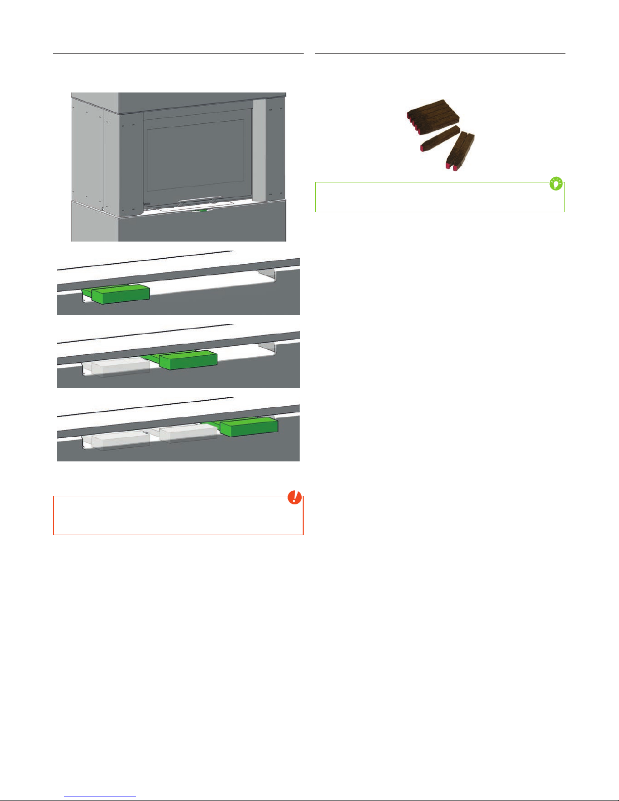
Combustion air regulation
The performance of your stove also depends on the chimney
draught; therefore the control knob for combustion air regulation
must be used according to your own experience�
The primary air intake is absolutely necessary for heating up� The
“heating-up position“ may only be used for heating up�
Note
The air control seals to 100%� Complete closing of the air regulator
(zero setting of control knob) during operation poses a hazard of
deflagration and is strictly prohibited�
If the stove is not in use, warm air can release through the chimney�
The zero position of the control knob can prevent this�
RIKA firelighter
Always ignite the RIKA firelighter on the red tip� One block consists
out of 8 ribs which can be divided to the desired size� The amount
of RIKA firelighters also depends on the size and humidity of your
firewood� Ideally, one rib is enough to light up the fire�
Tip
You can order the RIKA firelighter with the number E15834 at your
RIKA dealer�
Zero setting
0% primary air
0% secondary air
Middle position
0% primary air
100% secondary air
Heating-up position
100% primary air
100% secondary air
Page 17
|17
EN
16
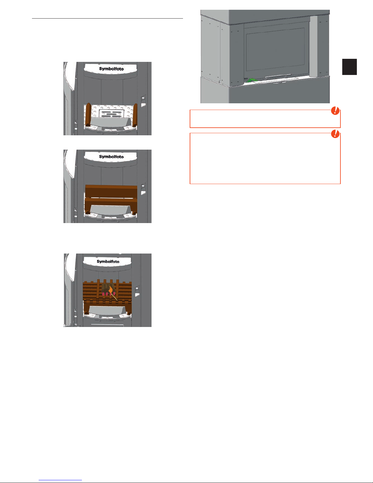
Correct heating up
1� Press the control knob completely into “heating-up position” –
primary and secondary air intakes are opened completely in the
heating-up position� Open the combustion chamber door and
sweep the ashes into the ashtray�
Place left and right two small pieces of chipboard lengthways in the
bottom of the combustion chamber�
Place two logs crossways on top of this chipboard�
2� Now place further pieces of chipboard in crosswise layers on top
of the logs and place 2-4 ribs of the RIKA-firelighter on the left on top
of the chipboard� Some uncoated paper can be placed underneath
the chipboard in case there is no firelighter available�
3� Now light the firelighter (or the uncoated paper) and close
the combustion chamber door� “Correct heating up” primarily
counteracts excessive smoke during heating up�
Set the control knob for combustion air regulation to middle position
some minutes later� The primary air intake is now closed and the
secondary air intake is completely open� The control can be set to
ideal position another few minutes later (depending on draught and
fuel quality / amount)�
After the first burn-off, again add two logs (see Amount of fuel)� Set
the control to “heating-up position” again until the wood is well lit�
Further regulation is effected as described in Item 3�
Please proceed in the same way for every further addition of wood�
Note
Use the handle “Cold Hands” or the RIKA heat-resistant glove for
every further addition of wood�
Note
Sometimes a lot of smoke develops when wood is placed on a
low firebed or when there is too less fresh air for combustion� An
explosive gas/air mixture may arise and cause an eventual heavy
deflagration� For safety reasons it is recommended to leave the
combustion chamber door closed and press the control knob at
the rear wall down completely into “heating-up position”� If the
log wood is not igniting, start a new heating-up procedure after it
stopped smoking�
Page 18
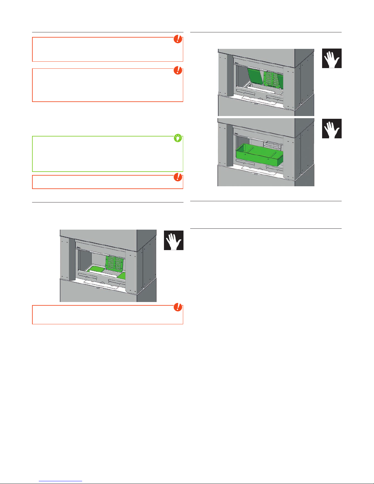
6. CLEANING AND MAINTENANCE
Basic information
Note
When you vacuum clean around the stove ensure that you do not
vacuum into the combustion air intake during heating operation�
You could vacuum out embers – FIRE RISK!
Note
Your stove must be cooled before any maintenance work is
performed�
Type Rikatronic4: Only work on the unit when it is switched off and
the mains plug has been disconnected�
The frequency with which the stove requires cleaning and the
maintenance intervals depend on the fuel you use� High moisture
content, ash, dust and chips may more than double the maintenance
required� Only use wood that has been stored properly and is dry
and untreated�
Tip
Wood as fertiliser - the mineral content of the wood remains in the
combustion chamber as ash as a residue of the combustion� This is
an excellent fertiliser for all plants in the garden; it is a completely
natural product� The ash should be stored first and slaked with
water�
Note
Ash may contain embers – only place ash in sheet steel containers!
Cleaning the combustion chamber
The combustion chamber must be regularly cleaned from ash to
ensure an adequate supply of air� If you remove the grate, you can
sweep the ashes with a broom in the ash tray� You can also use an
ash vacuum cleaner�
Note
Only when the stove is cold! You could vacuum out embers – FIRE
RISK!
Empty the ash drawer
Empty the ash drawer regularly� The ash drawer is simply lifted out
with the combustion chamber door open�
Cleaning painted surfaces
Wipe the painted surfaces with a damp cloth, do not scrub� Do not
use solvent-containing cleaners�
Cleaning the convection air openings
Vacuum clean any dust deposits from the convection air openings
at regular intervals�
The stove should be cleaned thoroughly prior to the start of the
heating season to prevent excess odour�
Page 19
|19
EN
18
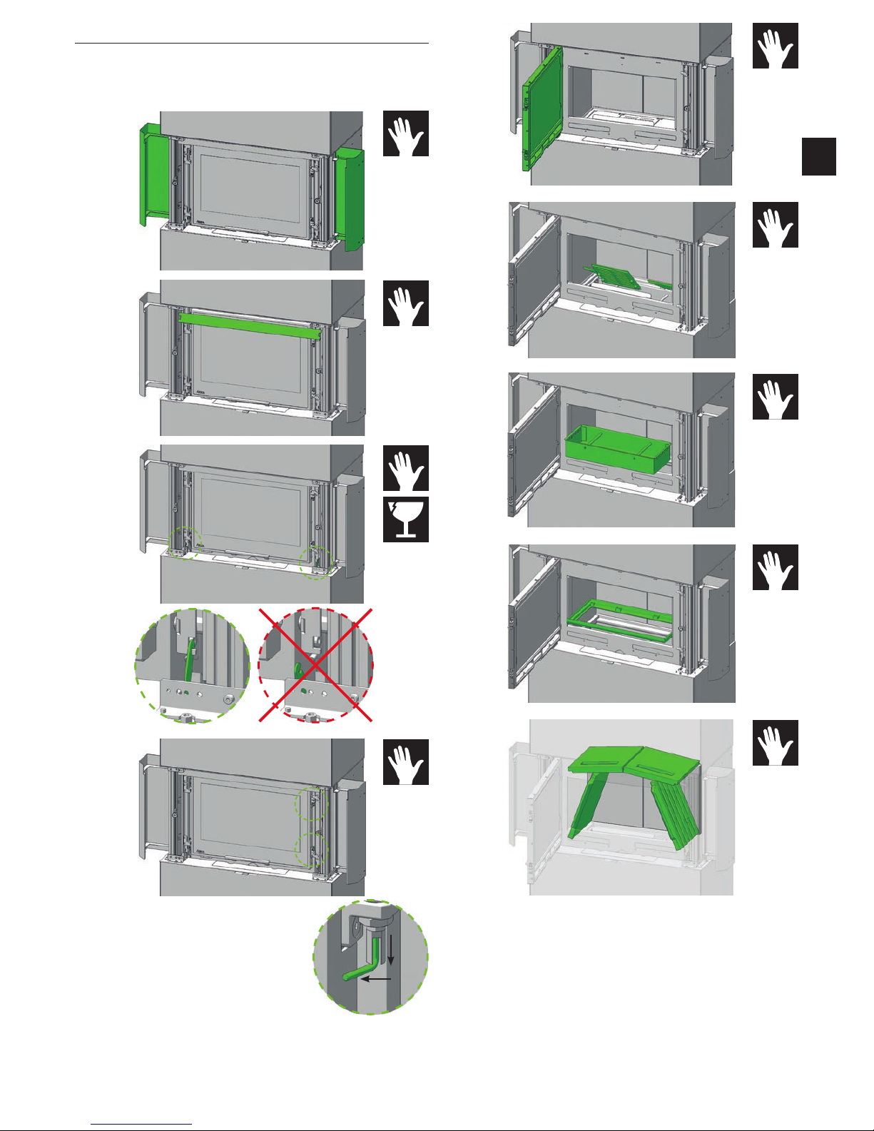
Cleaning the flue pipes
Annually!
Remove the flue pipes� Inspect and clean the chimney connection�
Brush off any soot and dust deposits in the fire and in the flue pipes
and vacuum�
1
2
Page 20
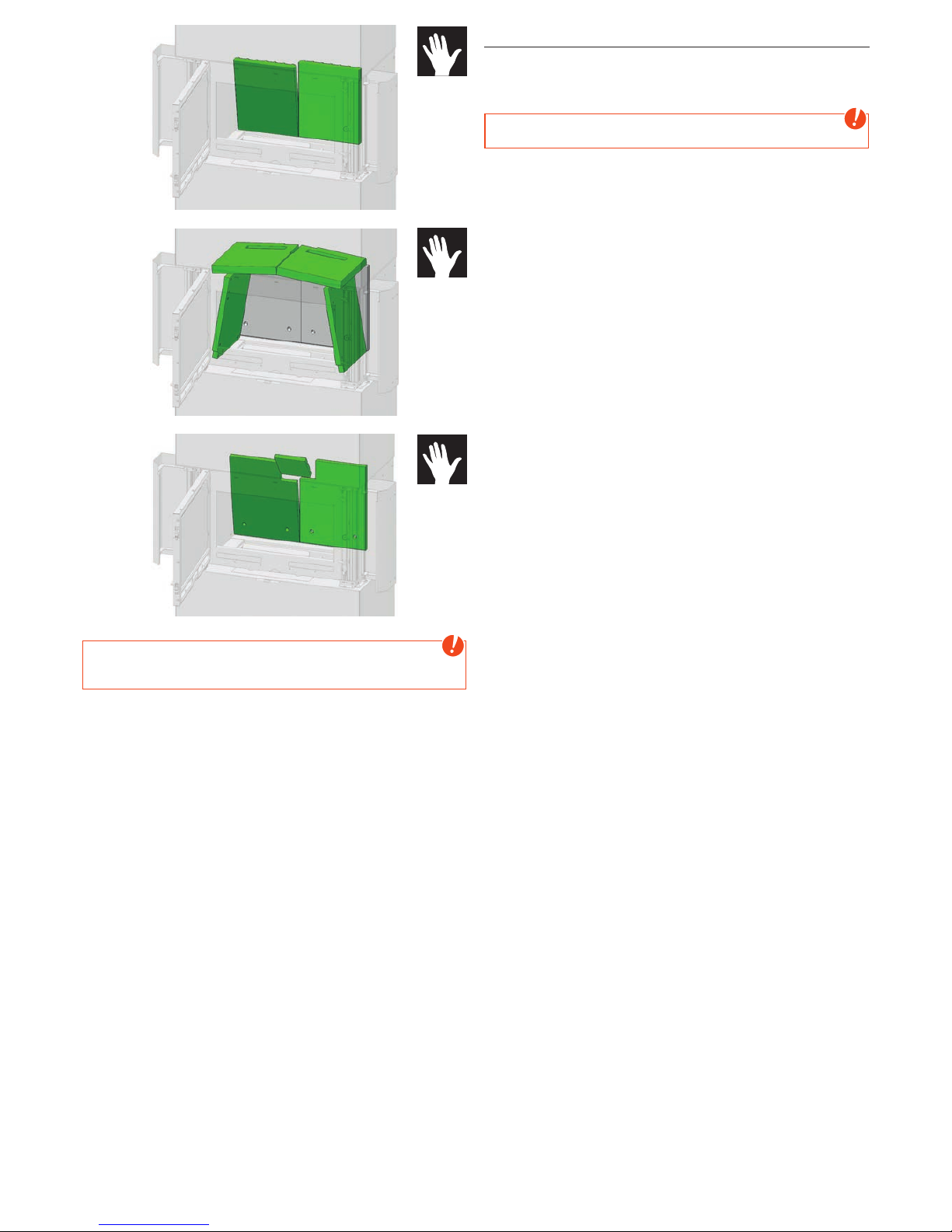
Note
Accumulated fly ash in the flue gas channels may impair the
performance of the stove and pose a safety risk�
Checking door seal
Annually!
The condition of the seals at doors and glass should be checked at
least once a year� Repair or replace seals depending on condition�
Note
Only intact seals ensure your stove works perfectly!
Page 21

|21
EN
20
7. PROBLEMS - POSSIBLE SOLUTIONS
Problem 1
Fire burns with weak, orange flame, window is sooted up�
Cause(s)
Q Poor chimney draught
Q Damp wood
Q Incorrect heating up
Q Stove is sooted over inside
Possible solutions
Q Check whether flue gas pipes are blocked with ash
(see CLEANING AND MAINTENANCE)
�
Q Use dry wood and correct fuel amounts
(see BRIEF INFORMATION ON COMBUSTIBLE - LOGS)
Q Check whether the suction nozzles and air inlet pipe or flue tube
are blocked�
Q Check door and cleaning cover seals for leaks
(see CLEANING AND MAINTENANCE)
Q Have service performed by authorised specialist company�
Q Every glass plate must be cleaned from time to time (depending
on use) with glass cleaner�
Problem 2
Stove smells strongly and / or fumes are emitted�
Cause(s)
Q Burning-in phase (taking into service)
Q Stove has accumulated dust and/or dirt
Possible solution(s)
Q Wait to end of burning-in phase and vent sufficiently
Q Suction off any dust deposits from the convection air openings at
regular intervals
Problem 3
Flue gas discharge when wood is added and during heating phase�
Cause(s)
Q Combustion chamber door opened too fast
Q Too much ash in combustion chamber
Q Adding logs to snappy
Q Chimney draught too low
Q Flue pipe connection leaks
Q Logs combustion still running (visible flame)
Possible solution(s)
Q open the combustion chamber door moderate
Q regular cleaning of combustion chamber (vacuum)
Q Adding logs carefully
Q Check chimney
Q Check connections and if necessary re-seal
Q Add logs after flame is gone
Q Check seals and replace (fire door, ��)
Page 22

8. WARRANTY
These warranty conditions are only valid for the following countries: Austria, Germany and Switzerland� Separate conditions imposed by the
importer apply for all other countries� In case of doubt as well as missing or incorrect translations, the German version is the only valid one�
For the purpose of timely damage limitation the claimant is required to file the warranty claim with the RIKA dealer in writing, submitting the
invoice and stating the purchase date, model name, serial number and reason for complaint�
Warranty
5 years on the welded stove body� This exclusively applies to defects in materials and workmanship as well as free replacement� Labour and
travel times are not included in the manufacturer’s warranty�
Only original parts supplied by the manufacturer should be used� Loss of warranty on non-observance!
The precondition for the warranty is that the stove has been installed and commissioned properly according to the User and installation
manuals valid at the time of purchase� Connection must be performed by a specialist for such stoves�
Any costs incurred by the manufacturer due to unjustified warranty claims are to be charged to the claimant�
Wear parts and parts affected by fire are excluded, such as glass, coating, surface coatings (e.g. handles, panels), seals, fire trough, grates,
draught plates, deflector plates, combustion chamber liners (e.g. fireclay), ceramics, natural stone, thermo stone, ignition elements,
sensors, combustion chamber sensors and temperature controller.
Also excluded from this warranty are all damages arising from non-observance of the manufacturer’s operating instructions of the unit,
or damage caused by overheating, use of nonapproved fuels, unauthorised tampering with the appliance or the flue gas pipe, electrical
excess voltage, an incorrect, insufficient or excessive flue draught, condensation, non-performance or deficient maintenance and cleaning,
nonobservance of the relevant and applicable building regulations, incorrect operation by the user or third parties, as well as any transport
and handling damage�
This manufacturer‘s warranty does not affect the statutory warranty provisions.
03�04�2018
Page 23

|23
EN
22
Your notes
Page 24

In case of doubt as well as missing or incorrect translations, the German version is the only
valid one. Technical and design changes, as well as typesetting and printing errors reserved.
© 2019 | RIKA Innovative Ofentechnik GmbH
RIKA Innovative Ofentechnik GmbH
Müllerviertel 20
4563 Micheldorf / AUSTRIA
Tel.: +43 (0)7582/686 - 41, Fax: -43
Z38218_Bedienungsanleitung_Insertronic | 15.01.2018
 Loading...