

Page 1

RIGOL
User’s Guide
EMI Measureme nt Application
Applicable to RSA5000-EMI/RSA3000-EMI
Feb. 2019
RIGOL (SUZHOU) TECHNOLOGIES INC.
Page 2

Page 3

RIGOL
Guaranty and Declaration
Copyright
© 2018 RIGOL (SUZHOU) TECHNOLOGIES INC. All Rights Reserved.
Trademark Information
RIGOL is a registered trademark of RIGOL (SUZHOU) TECHNOLOGIES INC.
Publication Number
UGD23101-1110
Software Version
00.02.00
Software upgrade might change or add product features. Please acquire the latest
version of the manual from RIGOL we bsite or contact RIGOL to upgrade the
software.
Notices
RIGOL produ cts are cov ered by P.R.C. and f oreign pa tents, issue d and pendin g.
RIGOL reserves the right to modify or change parts of or all the specifications
and pricing policies at the company’s sole decision.
Information in this publication replaces all previously released materials.
Information in this publication is subject to change without notice.
RIGOL shall not be liable for either incidental or consequential losses in
connection with the furnishing, use, or performance of this manual, as well as
any information contained.
Any part of th is d ocu ment is f orbi dden to be c opie d, ph oto copie d, o r rea r ran ged
without prior written approval of RIGOL.
Product Certification
RIGOL guarantees that this product conforms to the national and industrial
standards in China as well as the ISO9001:2015 standard and the ISO14001:2015
standard. Other international standard conformance certifications are in progress.
Contact Us
If you have any problem or requirement when using our products or this manual,
please contact RIGOL.
E-mail: service@rigol.com
Website: www.rigol.com
EMI User's Guide I
Page 4

RIGOL
Safety Requirement
General Safety Summary
Please review the following safety precautions carefully before putting the
instrument into operation so as to avoid any personal injury or damage to the
instrument and any product connected to it. To prevent potential hazards, please
follow the instructions specified in this manual to use the instrument properly.
Use Proper Power Cord.
Only the exclusive power cord designed for the instrument and authorized for use
within the local country could be used.
Ground the Instrument.
The instrument is grounded th rou gh t he Protective Earth lead of the power cord. To
avoid e lectr ic shock, connect the earth terminal of the power cord to the Protective
Earth terminal before connecting any input or output terminals.
Connect the Probe Correctly.
If a probe is used, the probe ground lead must be connected to earth ground. Do not
connect the ground lead to hi gh volta ge. Imp roper w ay of connection could resul t in
dangerous voltages being present on the connectors, controls or other surfaces of
the oscilloscope and probes, which will cause potential hazards for operators.
Observe All Terminal Ratings.
To avoi d fi re or s hock haza rd, observe all ratings an d ma rkers on the i nstrume nt and
check your manual for more information about ratings before connecting the
instrument.
Use Proper Overvoltage Protection.
Ensure that no over voltage (such as that caused by a bolt of lightning) can rea ch the
product. Otherwise, the operator might be exposed to the danger of an electric
shock.
Do Not Operate Without Covers.
Do not operate the instrument with covers or panels removed.
Do Not Insert Objects Into the Air Outlet.
Do not insert objects into the air outlet, as doing so may cause damage to the
instrument.
Use Proper Fuse.
Please use the specified fuses.
II EMI User's Guide
Page 5

RIGOL
Avoid Circuit or Wire Exposure.
Do not touch exposed junctions and components when the unit is powered.
Do Not Operate With Suspected Failures.
If you suspect that any damage may occur to the instrument, have it inspected by
RIGOL authorized personnel before further operations. Any mainte nance,
adjustment or replacement especially to circuits or accessories must be performed
by RIGOL autho rized pers onnel.
Provide Adequate Ventilation.
Inadequate ventilation may cause an increase of temperature in the instrument,
which would cause damage to the instrument. So please keep the instrument well
ventilated and inspect the air outlet and the fan regularly.
Do Not Operate in Wet Conditions.
To avoid short circuit inside the instrument or electric shock, never operate the
instrument in a humid environment.
Do Not Operate in an Explosive Atmosphere.
To avoid personal injuries or damage to the instrument, never operate the
instrument in an explosive atmosphere.
Keep Product Surfaces Clean and Dry.
T o a void dust or moisture from af fecting the pe rformance of the inst rument, keep th e
surfaces of the instrument clean a nd d ry.
Prevent Ele c tr o static Imp a ct.
Operate the instrume nt i n an el ectr ostatic dischar ge protectiv e e nvi ron ment to a void
damage induced by static discharges. Always ground both the internal and external
conductors of cables to relea s e stati c befo re making connections.
Use the Battery Properly.
Do not expose the battery (if available) to high temperature or fire. Keep it out of the
reach of children. Improper change of a battery (lithium battery) may cause an
explosion. Use the RIGOL specified battery only.
Handle with Caution.
Please handle with care during transportation to avoid damage to keys, knobs,
interfaces, and other parts on the panels.
EMI User's Guide III
Page 6
RIGOL
WARNING
avoided, will result in serious injury or death.
CAUTION
avoided, could result in damage to the product or loss of important data.
DANGER
It calls attention to an operation, if not correctly performed, could
result in injury or hazard immediately.
WARNING
It calls attention to an operation, if not correctly performed, could
result in potential injury or hazard.
CAUTION
It calls attention to an operation, if not correctly performed, could
product.
Hazardous
Voltage
Safety Warning
Protective Earth
Terminal
Chassis Ground
Test Ground
Safety Notices and Symbols
Safety Notic e s in this Manua l:
Indicates a potentially hazardous situation or practice which, if not
Indicates a potentially hazardous situation or practice which, if not
Safety Terms on the Product:
result in damage to the product or other devices connected to the
Safety Symbols on the Product:
IV EMI User's Guide
Page 7
RIGOL
CAUTION
WARNING
supply.
Care and Cleaning
Care
Do not store or leave the instrument where it may be exposed to direct sunlight for
long periods of time.
Cleaning
Clean the instrument regularly according to its operating conditions.
1. Disconnect the instrument from all power sources.
2. Clean the external surfaces of the instrument with a soft cloth dampened with
mild detergent or water . Avoid havin g any water or o ther objects into the chassis
via the heat dissipation hole. When cleaning the LCD, take care to avoid
scarifying it.
To avoid damage to the instrument, do not expose it to caustic liquids.
To avoid short-circuit resulting fr om moisture or personal injuries, ensure
that the instrument is completely dry before connecting it to the power
Environmental Consideratio ns
The following symbol indicates that this product complies with the WEEE Directive
2002/96/EC.
Product End-of-Life Handling
The equipment may contain substances that could b e harmf ul to t he envi ronm ent o r
human health. To avoid the release of such substances into the environment and
avoid harm to human health, we recommend you to recycle this product
appropriately to ensure that most materials are reused or recycled properly. Please
contact your local authorities for disposal or recycling information.
You can click on the following link
http://www.rigol.com/Files/RIGOL_RoHS2.0&WEEE.pdf to download the latest
version of the RoHS&WEEE certification file.
EMI User's Guide V
Page 8

RIGOL
RSA Series Spectrum Analyzer Overview
RSA series is a new generation of cost-ef ficient real-time spectrum analyzer with hi gh
performance. With superb performance specifications, clear user interface, the RSA
series allows you to operate it through various ways, such as pressing keys on the
front panel, using the touch screen, connecting the mouse and the keyboard.
Remote communication interfaces are also available. The instrument can be widely
used in education science, corporate R&D, industrial production, and other fields.
Document Overview
This document mainly introduces the front panel functions of the EMI mode.
Topics in this Manual:
Chapter 1 Quick Start
This chapter introduces the user interfa ce of the spe ctrum analy zer in EMI mode and
its mode settings.
Chapter 2 Front Panel Function Keys
This chapter gives detailed function descriptions of the EMI's front panel keys and
the associated menu keys.
Chapter 3 Appendix
This chapter lists the options and accessories that can be ordered along with your
analyzer as well as the service and support information.
Format Conventions in this Manual:
1. Keys:
The keys on the front panel are usually denoted by the format of "Key Name
(Bold) + Text Box". For example, FREQ denotes the FREQ key.
2. Menu keys:
The menu softkeys are usually denoted by the format of "Menu Word (Bold) +
Character Shading". For example, Midspan Freq denotes the midspan menu
item under the FREQ funct i on key.
3. Connectors:
The connectors on the front or rear panel are usually denoted by the format of
"Connector Name (Bol d) + Squ are Br ackets (Bold)". For example , [Gen Output
50Ω].
4. Operation Procedures:
indicates the next step of operation. For example, FREQ Midspan Freq
VI EMI User's Guide
Page 9
RIGOL
Model
Frequency Range
TG
RSA5065
9 kHz to 6.5 GHz
None
RSA5032
9 kHz to 3.2 GHz
None
RSA5065-TG
9 kHz to 6.5 GHz
6.5 GHz
RSA5032-TG
9 kHz to 3.2 GHz
3.2 GHz
RSA3045
9 kHz to 4.5 GHz
None
RSA3030
9 kHz to 3 GHz
None
RSA3045-TG
9 kHz to 4.5 GHz
4.5 GHz
RSA3030-TG
9 kHz to 3 GHz
3 GHz
indicates pressing FREQ on the front panel and the n p ressing the menu so ftkey
Midspan Freq.
Content Con v entions in th is Man ual:
The RSA series spectrum analyzer includes the following models. This manual takes
RSA5065-TG as an example.
User Manual s of this Product:
Quick Guide, User’s Guide, Programming Guide, Data sheet, etc. For the desired
manual, please download it from www.rigol.com.
EMI User's Guide VII
Page 10

RIGOL Contents
Contents
Guaranty and Declaration ......................................................................... I
Safety Requirement ................................................................................. II
General Safety Summary........................................................................... II
Safety Not ices and Symbols ..................................................................... IV
Care and Cleaning .................................................................................... V
Environmental Considerations .................................................................... V
RSA Series Spectrum Analyzer Overview ................................................ VI
Document Overview ............................................................................... VI
Chapter 1 Qui ck Start ........................................................................ 1-1
User Interface ........................................................................................ 1-2
Mode Setting ......................................................................................... 1-5
Mode .............................................................................................. 1-5
Mode Setup .................................................................................... 1-6
Install the Option ................................................................................... 1-8
Chapter 2 Front Panel Function Keys ................................................. 2-1
Basic Settings ........................................................................................ 2-2
FREQ .............................................................................................. 2-2
SPAN .............................................................................................. 2-5
AMPT ............................................................................................. 2-6
Sweep and Function Settings................................................................... 2-9
BW ................................................................................................. 2-9
Sweep .......................................................................................... 2-11
Trigger ......................................................................................... 2-13
Trace ............................................................................................ 2-16
Measuremen t Settings .......................................................................... 2-19
Meas ............................................................................................ 2-19
Meas Setup ................................................................................... 2-19
Marker Measurement ............................................................................ 2-30
Marker .......................................................................................... 2-30
Marker-> ...................................................................................... 2-34
Marker Func .................................................................................. 2-35
Peak ............................................................................................. 2-37
Input/Output ....................................................................................... 2-40
Input Impe da nce ........................................................................... 2-40
Ext Gain ....................................................................................... 2-40
Ext Trigger2 .................................................................................. 2-40
Corrections ................................................................................... 2-41
Shortcut Key ........................................................................................ 2-43
Auto Tune ..................................................................................... 2-43
Preset........................................................................................... 2-43
VIII EMI User's Guide
Page 11

Contents RIGOL
User ............................................................................................. 2-46
Quick Save .................................................................................... 2-46
Cont ............................................................................................. 2-46
Single ........................................................................................... 2-46
System Fu nction ................................................................................... 2-47
System ......................................................................................... 2-47
File ............................................................................................... 2-56
Recall ........................................................................................... 2-60
Save ............................................................................................. 2-63
Chapter 3 Appendix ............................................................................ 3-1
Appendix A: RSA5000 Accessories and Option List .................................... 3-1
Appendix B: RSA3000 Accessories and Option List .................................... 3-2
Appendix C: Warr anty ............................................................................ 3-3
Index ....................................................................................................... 1
EMI User's Guide IX
Page 12

Page 13

Chapter 1 Quick Start RIGOL
Chapter 1 Quick Start
This chapter gives you a quick review about the user interfac e, mode settings, and
option installation in the EMI mode of the RSA series spectrum analyzer. For its
appearance and dimens ions, its front an d rear panel, and precautions during first use
of the analyzer, refer to relevant chapters in
User's Guide
Contents in this chapter:
User Interface
Mode Setting
Install the Option
.
RSA5000 Use r's Guide
and
RSA3000
EMI User's Guide 1-1
Page 14
RIGOL Chapter 1 Quick Start
No.
Name
Description
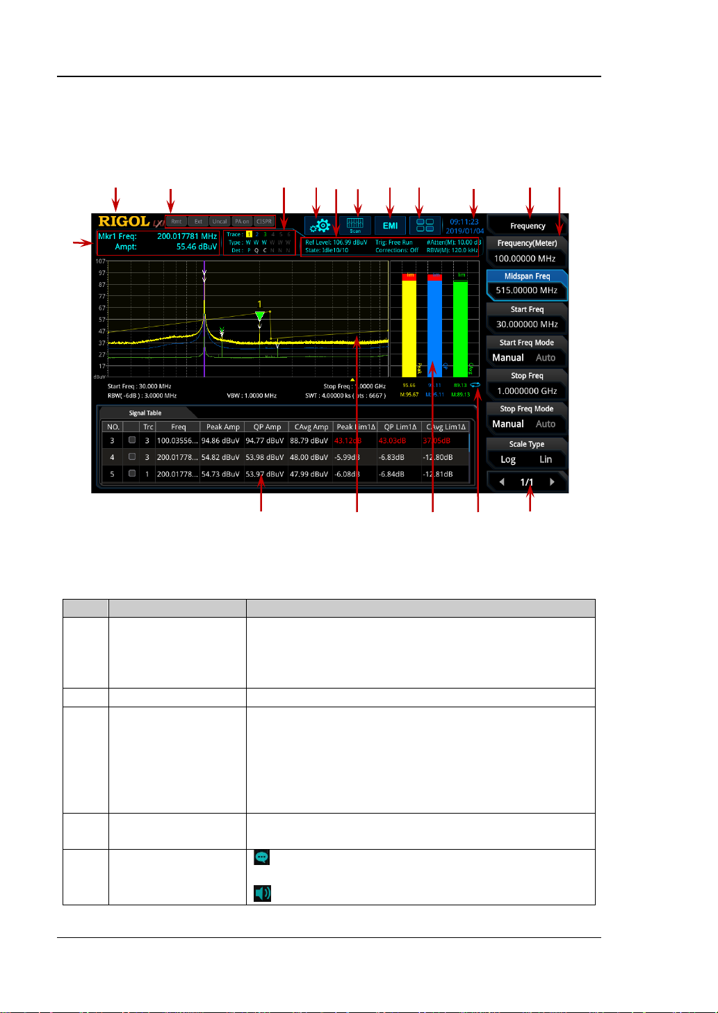
1
Marker
Displays the current measurement results f or the
Span).
2
RIGOL
Company logo.
3
System status
Rmt: indicates remote operation.
CISPR: indicates that the EMC standard.
4
Trac e indicat or
[1]
Displays information abo ut the trace and the
detector.
5
Information setting
: indicates messages, such as the prompt
: indicates the speaker. You can tune it up and
2 3 4 5 6 7 8 9 10 11 12
1
17 16 15 14 13
User Interface
The user interface of EMI mode is shown in the following figure.
Figure 1-1 User Interface (EMI Mode)
Table 1-1 User Interface Icons
measurement
result
marker (when n o ma rker exists, the measurement
results display Frequency( Meter), Mids pan Freq, and
Ext: indicates the external reference.
Uncal: indicates that the measurement has not be
calibrated.
PA on: indic ates that the preamp has been enabled.
messages, alarm messages, and error messages.
1-2 EMI User's Guide
Page 15
Chapter 1 Quick Start RIGOL
down to increase and decrease the speaker volume,
inserted.
6
Measurement bar
Displays measurement settings.
7
Measurement
function
Displays the currently selected measurement
function.
8
Worki ng mode
Displays the currently selected working mode.
9
Function keypad
icon
Clicks/Touches the icon to display the function
keypad interface.
10
Time
Displays the system time.
11
Menu title
Displays the currently selected menu name.
12
Menu item
Displays the menu item of the current function.
13
Menu page
number
Displays the current page and the total number of
pages.
14
Meter
mode
: indicates continue; : indicates single.
15
Meter display area
Displays the histogram of the meter and its
parameter informati o n.
16
Trace display area
Displays the scanned spectral trace and the setting
information after the pre-scan is performed.
17
Signal table display
area
Displays the searched sig nal, which corre sp ond to
the marks in the trace.
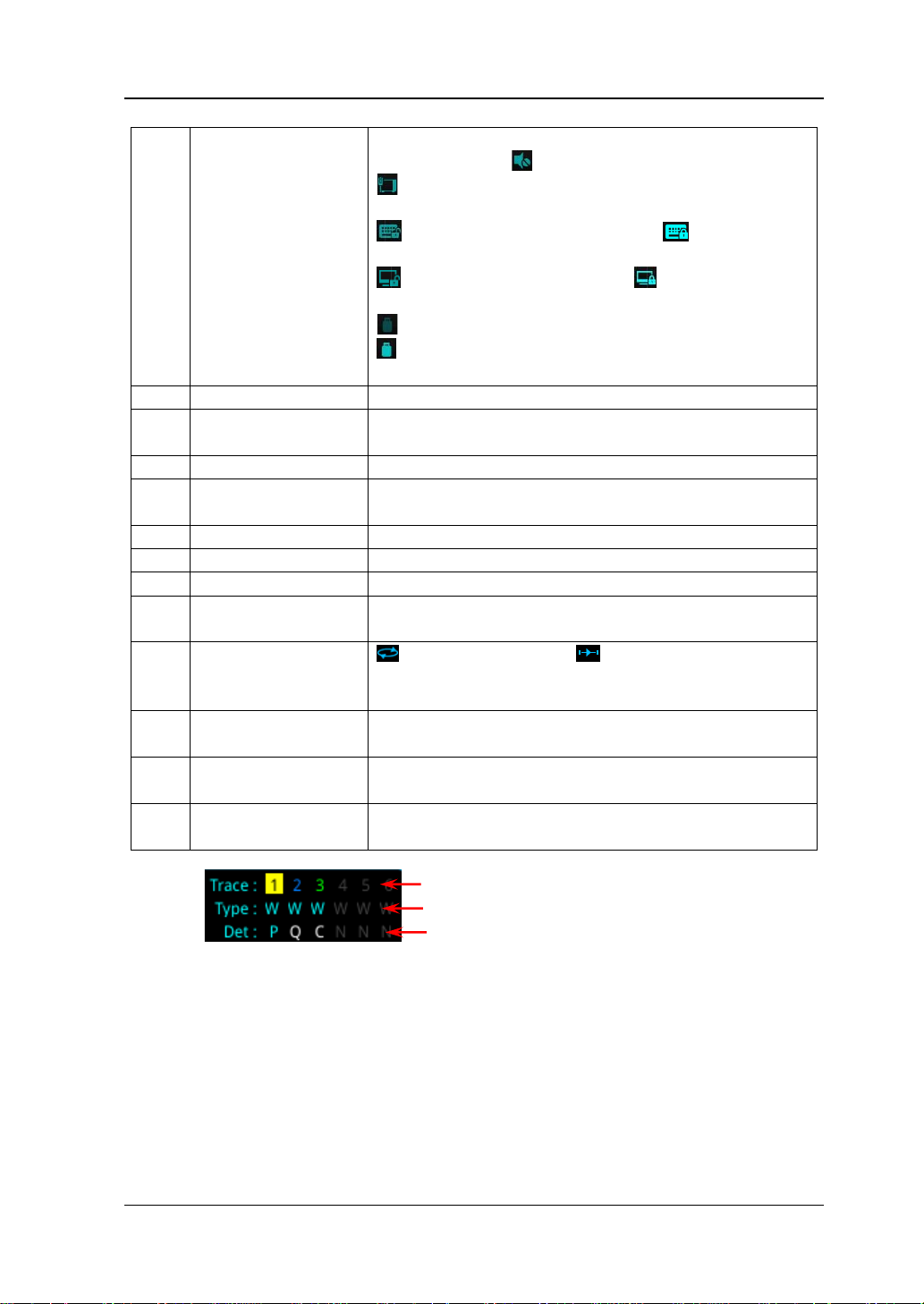
Trace Number
Trace Type
Detector Type
or set it to mute .
: indicates the network settings. You can
configure network parameters.
: unlocks the front panel keys; : locks the
front panel keys.
: unlocks the touch screen; : locks th e t ouch
screen.
: indicates that no USB sto ra ge device is inserte d;
: indicates that a USB storage device has been
measurement
[1]:
Note
The display of the trace indicator is shown in the following figure:
The first line displays the trace number. The color of the number is the same as that of
the trace. EMI mode only supports 3 traces.
The second line displays the trace type, including W (Clear/Write), A (Trace Average),
M (Maximum Hold), and m (Minimum Hold). The letters with different co l o r s an d in
different forms show different meanings:
— The letter in blue indicates that the trace is updating.
— The letter in gray indicates that the trace is not updated.
— The letter with strikethrough and in gray color indicates that the trace will neither
be updated nor displayed.
— The letter with strikethrough and in blue color indicates that the trace is updating
but not displayed. It is useful in trace math operation.
EMI User's Guide 1-3
Page 16

RIGOL Chapter 1 Quick Start
The third line displays the detector type of each trace, including P (Positive Peak), p
(Negative Peak), C (CISPR Av erage), R (RMS A verag e), Q (Quasi Pea k), and V (V oltage
Average). The letter in blue in the third line (detector type) indicates that the detector
is in auto state; the letter in white indicates that it is in manual state.
1-4 EMI User's Guide
Page 17

Chapter 1 Quick Start RIGOL
Mode Setting
Mode
RSA provides four wor king modes: GPSA, RTSA, VSA (option), and EMI (option).
Press Mode to select the working mode.
Note: In different working modes, the functions of the keys on the front panel may
be different. Press Help t o display the help infor mation of the current working mode.
If you need help information for other modes, please exit the help interface first.
Then select the desired wor king mode and obtain the corresponding help
information.
1. GPSA
GPSA adopts two analysis methods: swept SA and FFT. It can not only carry out
frequency domain analysis, but also time domain (zero span) analysis.
Select GPSA. In this working mode, you can press Meas to select multiple
measurements. For details, refer to relevant chapters in Chapte r 2 of
or
User's Guide
2. RTSA
RTSA provides the analysis function for the real-t im e signal, which can capture
the complex signal seamlessly.
Select RTSA. In this working mode, you can also press Meas to select multiple
measurements. For details, refer to relevant chapters in C hapter 3 of
User's Guide
3. VSA
VSA mode provides the s tandard vector s ignal analysis f unction. If you need this
function, please purchase this option (order No. RSA5000-VSA), and install it
according to instructions in "Install the Option".
4. EMI
EMI mode provides the EMI precom patibility measurement function. If you need
this function, please purchase this option (order No.
RSA5000-EMI/RSA3000-EMI), and install it according to instru ctions in "Install
the Option".
Note: when you purchase the RSA3000-EMI option, there is no need to
repeatedly purchase EMC filter and quasi-peak detector kit RSA3000-EMC. The
RSA3000-EMI option contains all the functions of RSA3000-EMC.
RSA3000 User's Guide
or
RSA3000 User's Guide
.
.
RSA5000
RSA5000
EMI User's Guide 1-5
Page 18

RIGOL Chapter 1 Quick Start
Mode Setup
The Mode Setup menu is used to set parameters related to the working mode.
Open the global parameter setting menu for the selected working mode under
Mode.
Global CF Mode
Turns on or off the global center fr equency. In any working mode, if you enable the
global center frequency mode, then the global center freque ncy will be set to the
center frequency of the current mode. When a different working mode is selected,
the global center frequency will be set to the center frequency of the previous
working mode, that is, the one that is before switching the working mode. If you
change the center frequency in any working mode, then the global center frequency
will change with it.
Global CF
Sets the global center frequency. It is only available when you turn on the global
center frequency.
Mode Preset
Resets the parameters of the current mode to be the factory default settings.
EMC Standard
Sets the EMC standard to "None" or "CISPR".
When "None" is selected, the filter type is set to Gauss. At this point, the filter
bandwidth is -3 dB. The instrument will switch to "CISPR" standard
automatically when "Quasi Peak", "CISPR Average" or "RMS Average" detector is
selected. The filter type is set to EMI. At this point, the filter bandwidth is -6 dB.
When "CISPR" is selected, for Meter 1, the detector is, by default, positive peak;
for Meter 2, the detector is, by default, quasi peak; for Meter 3, the detector is,
by default, CISPR average.
1-6 EMI User's Guide
Page 19

Chapter 1 Quick Start RIGOL
Meters Control
Sets the parameters of the meter.
1. Meters
1) Select Meter
Specifies the currently selected meter to "Meter1", "Meter2", or "Meter3".
2) Meter
Enables or disables the selected meter.
When enabled, the histogram of the selected meter is displayed in the
meter display area of the user interface, and the corresponding
detector type is selected to perform the measurement.
When disabled, the selected meter is not displayed and the system will
not perform the measurement.
3) Detector
Sets the detector of the selected meter, including "Pos Peak", "Quasi Peak",
"CISPR Average", "RMS Average", "Average(Vol)", and "Neg Peak".
Note: "Quasi Peak", "CISPR Average", "RMS Average", and "Average(Vol)"
are mutually exclusive. You can at most select two among the thr ee items
("Quasi Peak", "CISPR Average", and "R MS Average" ).
4) Limit
Sets the limits of the selected meter.
5) Limit State
Enables or disables the limit line of the selected meter.
2. Dwell Time
Sets the dwell time of the meter detector.
3. Peak Hold Time
1) Peak Hold Type
Sets the max hold time type of the meter to "Adjust" or "Infinite".
When "Infinite" is sele cted, the peak hold line of the selected meter will
not be reset. The Adjust Time menu is grayed out and disabled.
When "Adjust" is selected, the peak hold line of the selected meter will
be reset to the current signal value after the set peak hold t ime. At this
time, you can use the Adjust Time menu to set the peak hold time.
2) Adjust Time
Sets the peak hold time of the meter.
4. Reset Peak Hold
Resets the peak hold lines of all the currently enabled meters to the current
EMI User's Guide 1-7
Page 20

RIGOL Chapter 1 Quick Start
signal value.
5. Couple to Signal
Enables or disables the coupling function of the meter and the signal tabl e.
When enabled, the instrument will sear ch f or the s ignal frequency that is closest
to that of the current meter from the signal table automatically and mod ify the
meter frequency to the frequency of the signal.
6. Couple to Marker
Enables or disables the coupling function of the meter and the marker. When
enabled, the instrument w ill set the meter frequency to the current frequency at
the marker.
Install the Option
RSA provid es various options (for option information, refer to "Access or ies and
Option List") to expand the function of the spectrum analyzer. If you need to
purchase the option, please contact RIGOL sales representative. After you have
purchased the option successfully, you will get the c orresponding key. Then perform
the following operations to install the option.
1. Acquire the License of the Option
Log in to the RIGOL official website (www.rigol.com), click License
Activation to enter the "Registered product license code" interface.
Input the correct key, serial number (press System About System
System Info to acquire the serial number of the instrument), and
verification code. Click Generate to acquire the option license. In the
license generation interface, click Download to download and save the
license file to the PC.
2. Install the Option
You can install the option via the following 2 m ethods.
1) Install the option by reading the license file from the USB storage dev ice
Copy the saved option license file to the root directory of the USB
storage device.
Power on the inst rument and insert the USB sto ra ge device. Press File
to enter the file operation menu interface.
Press File Explorer, and then the file manager interface is displayed.
In the interface, find the directory of the USB storage device. Then
select the desired option license file (suffixed wit h ".lic"). Press Import
License to import the activation code and complete the reading of the
option installation file.
2) Install the option by sending SCPI Commands
1-8 EMI User's Guide
Page 21

Chapter 1 Quick Start RIGOL
Log in to RIGOL official website (www.rigol.com) to download the
software Ultra Sigm a. Then install it according to the installation
wizard.
Use the USB cable to connect the rear-panel USB DEVICE int e rface of
RSA to the USB HOST interface of the PC.
Run Ultra Sigma. Search the resource and right-click the resource
name. In the displayed menu, select "SCPI Panel Control". Input the
following option installation command in the displayed SCPI control
panel: :SYSTem:LKEY <option info>@<lic ense info>
<option info>
indicate s the optio n or der No., and <license info>
. Wherein,
indicates the option license code.
For example, the following command is used to install the option
RSA5000-PA.
:SYSTem:LKEY
RSA5000-PA@8AD12B8EBC5DF492D1D4289B7CBA5B6150BF6F5D752
D645C36D74530B05F39B49C461B23A50D6C94A34E06782AC4380070
B0D1A86BA84E02768391FFD70C2103
EMI User's Guide 1-9
Page 22

Page 23

Chapter 2 Front Panel Function Keys RIGOL
Chapter 2 Front Panel Function Keys
This chapter describes in detail the front-panel function keys of RSA and their
associated menu functions in EMI mode.
Contents in this chapter:
Basic Settings
Sweep and Function Settings
Measurement Settings
Marker Measurement
Input/Output
Shortcut Key
System Fu nction
EMI User's Guide 2-1
Page 24

RIGOL Chapter 2 Front Panel Function Keys
start
f
stop
f
center
f
span
f
2)(
startstopcenter
fff +=
startstopspan
fff −=
Parameter
Remarks
Default
515 MHz
Range
0 Hz to Fmax
[1]
Unit
GHz, MHz, kHz, Hz
Knob Step
Left/Right Arrow Key Step
Up/Down Arrow Key Step
step = RBW (mete r)*10
Basic Settings
FREQ
Sets the frequency parameters of the analyzer.
The frequency range of the current channel can be expressed by either of two
/
groups of parameters: Start Frequency/Stop Frequenc y (
); or Span
Center Frequency/Span (
/
). If any of the f our pa ra met ers is chan ged, t he
other three parameters will make adjustment automatically to ensure the coupling
relationship among them:
(2-1)
(2-2)
Frequency(Meter)
It is used to set the frequency of the meter in frequency scan. You ca n u se the
numeric keys, the knob, or ar row keys to modify this parameter; y ou can also u se the
touch screen to modify the parameter.
Note: In the trace display area of the user interface, a purple v ertical line is used to
mark the frequency of the meter. Press System Display Meters Freq Line,
you can turn on or of f a purple vertical line.
Table 2-1 Frequency (Meter)
[1]
Note
RSA5065, Fmax is 6.5 GHz; for RSA5032, Fmax is 3.2 GHz. For RSA3045, Fmax is 4.5 GHz; for
RSA3030, Fmax is 3 GHz.
: The maximum measurement frequency Fmax is determined by the instrument model. For
2-2 EMI User's Guide
step = RBW (meter)/2
Page 25
Chapter 2 Front Panel Function Keys RIGOL
Parameter
Remarks
Default
515 MHz
Range
5 Hz to (Fmax - 5 Hz)
Unit
GHz, MHz, kHz, Hz
Knob Step
Left/Right Arrow Key Step
Up/Down Arrow Key Step
step = RBW (mete r)*10
Parameter
Remarks
Default
midspan frequency - span/2
Range
0 Hz to (Fmax – 10 Hz)
Unit
GHz, MHz, kHz, Hz
Knob Step
Left/Right Arrow Key Step
Up/Down Arrow Key Step
step = RBW (mete r)*10
Midspan Freq
Sets the center frequency of the current channel.
Remarks:
When you modify the midspan frequency, the start and stop frequency will be
modified automatically if the span remains to be unchanged.
Modifying the midspan frequency indicates that the frequency is changed along
the current channel horizontally, and the adj ustable range should be within the
frequency range specified in the technical specifications of the analyzer.
You can use the numeric keys, the knob, or arrow keys to modify this parameter;
you can also use the touch screen to modify the parameter.
Table 2-2 Midspan Freq
step = RBW (meter)/2
Start Freq
Sets the start frequency of the current frequency channel.
Remarks:
When you modify the start frequency, the span and midspan fre quen cy will be
changed.
You can use the numeric keys, the knob, or arrow k eys to modif y this par ameter;
you can also use the touch screen to modify the parameter.
Table 2-3 Start Freque ncy
step = RBW (meter)/2
EMI User's Guide 2-3
Page 26
RIGOL Chapter 2 Front Panel Function Keys
Parameter
Remarks
Default
midspan frequency + span/2
Range
10 Hz to Fmax
Unit
GHz, MHz, kHz, Hz
Knob Step
Left/Right Arrow Key Step
Up/Down Arrow Key Step
step = RBW (mete r)*10
Start Freq Mode
Sets the coupling mo de o f the st art frequen cy to "Manual" or "Auto". When "Auto" is
selected, the start frequency will automatically couple to the start frequenc y of the
first range among the currently enabled ranges in the scan table.
Stop Freq
Sets the stop frequency of the current frequency channel.
Remarks:
When you modify the stop frequency, the span and midspan frequency will be
changed.
You can use the numeric keys, the knob, or arrow k eys to modif y this par ameter;
you can also use the touch screen to modify the parameter.
Table 2-4 Stop Frequency
step = RBW (meter)/2
Stop Freq Mode
Sets the coupling mode of the stop frequency to "Manual" or "Auto". When "Au to" is
selected, the stop frequency will automatically coup le to th e stop frequency of the
first range among the currently enabled ranges in the scan table.
Scale Type
Sets the scale type of X-axis to Lin or Log.
Remarks:
The X-axis scale type is only related to data display, and w ill not affect scan and
trace data.
Modifying the X-axis scale type will neither restart the scan nor affect the
number of scan points.
2-4 EMI User's Guide
Page 27

Chapter 2 Front Panel Function Keys RIGOL
Parameter
Remarks
Default
970 MHz
Range
10 Hz to Fmax
Unit
GHz, MHz, kHz, Hz
Knob Step
Left/Right Arrow Key Step
Up/Down Arrow Key Step
at 1-2-5 step
SPAN
Sets the span of the analyzer. Changing this parameter will chang e the frequency
parameters.
Span
Sets the frequency range of the current channel.
Remarks:
When you modify the span, the start and stop frequency will b e modified
automatically if the midspan frequency remains to be unchanged.
You can use the numeric keys, the knob, or arrow k eys to modif y this par ameter;
you can also use the touch screen to modify the parameter.
Table 2-5 Span
step = span/200, Min = 2 Hz
EMI User's Guide 2-5
Page 28
RIGOL Chapter 2 Front Panel Function Keys
Parameter
Remarks
Default
106.99 dBuV
Range
-63.01 dBuV ~ 136.99 dBuV
Unit
dBm, dBmV, dBuV, V, W
Knob Step
Left/Right Arrow Key Step
Up/Down Arrow Key Step
step = scale
AMPT
Sets the amplitude parameters of the analyzer. You can modify these parameters to
make the signals under test be displayed with minimal errors in the cur rent window,
easy for you to observe .
Ref Level
Sets the maximum power o r voltage that can be displayed in the current window.
Remarks:
The RF link is limited by the maximum mixer level, so when you reduce the
attenuation, the instrument m ay reduce the reference level to meet the mixer
level limit. When you increase the attenuation, the reference level remains
unchanged.
You can use the numeric keys, the knob, or arrow k eys to modif y this par ameter;
you can also use the touch screen to modify the parameter.
Table 2-6 Ref Level
step = scale/10
Att(Meter)
Sets the meter attenuator.
Remarks:
In the frequency scan m easurement, this value only affects the attenuation of
the meter.
You can use the numeric keys, the knob, or arrow k eys to modif y this par ameter;
you can also use the touch screen to modify the parameter.
2-6 EMI User's Guide
Page 29

Chapter 2 Front Panel Function Keys RIGOL
Parameter
Remarks
Default
0 dB
Range
0 dB to 50 dB
Unit
dB
Knob Step
Left/Right Arrow Key Step
Up/Down Arrow Key Step
5 dB
×=
0.001W
1
R
2
Volts
10lgdBm
=
V1
Volts
20lgVdB
µ
µ
=
1mV
Volts
20lgdBmV
R
2
Volts
Watts
=
R
Table 2-7 Att(Meter)
preamp off, step = 1 dB
RF Preamp(Meter)
Sets the meter preamplifier to be on or off . Whe n the signal under test is a lo w-level
signal, turning on the preamp lifier can reduce the displayed average noise level, so
that you can distinguish low-lev el signals f rom the n oise. By defa ult, the p reamp gain
is 20 dB.
Y Axis Unit
Sets the unit of the Y-axis to dBm, dBmV , dBμV, Volts, or Watts. Wherein, dBm, dB mV,
and dBμV are for Lo g s cale; Volts and Watts are fo r Linear scale. The default unit is
dBuV.
Remarks:
The conversion relations between units are as follows:
Wherein,
denotes the reference resistance.
EMI User's Guide 2-7
(2-3)
(2-4)
(2-5)
(2-6)
Page 30

RIGOL Chapter 2 Front Panel Function Keys
Parameter
Remarks
Default
10 dB
Range
0.1 dB to 20 d B
Unit
dB
Knob Step
scale ≥ 1, step = 1 dB
scale < 1, s t e p = 0.1 dB
Left/Right Arrow Key Step
Up/Down Arrow Key Step
at 1-2-5 step
Parameter
Remarks
Default
0 dB
Range
-300 dB to 300 dB
Unit
dB
Knob Step
level offset ≥ 1 or level offset ≤ -1: step = 1 dB;
-1 < level offset < 1, step = 0.1 dB
Left/Right Arrow Key Step
Up/Down Arrow Key Step
5 dB
Scale/Div
Sets the unit per division in the vertical axis.
Remarks:
The amplitude range to be displayed can be adjusted by setting the scale.
The range of the signal amplitude that can be displayed is as follows:
Minimum: reference level – 10 × current scale value
Maximum: reference level
You can use the numeric keys, the knob, or arrow keys to modify this parameter;
you can also use the touch screen to modify the parameter.
Table 2-8 Scale/Div
Ref Offset
Adds an offset value to the reference level to compensate for gains or losses
generated between the DUT and the analyzer input.
Remarks:
The offset value does n ot aff ect the tr a ce posit ion, but will modif y the ref e rence
level readout and the marker amplitude readout.
You can use the numeric keys, the knob, or arrow k eys to modif y this par ameter;
you can also use the touch screen to modify the parameter.
Table 2-9 Reference Level Offset
2-8 EMI User's Guide
Page 31

Chapter 2 Front Panel Function Keys RIGOL
Parameter
Remarks
Default
120 kHz
Range
100 Hz to 10 MHz
[1]
Unit
GHz, MHz, kHz, Hz
Knob Step
Left/Right Arrow Key Step
Up/Down Arrow Key Step
at 1-3-10 step
Frequency (Meter) Fmet
RBW
Fmet < 150 kHz
200 Hz
150 kHz ≤ Fmet < 30 MHz
9 kHz
30 MHz ≤ Fmet < 1 GHz
120 kHz
Fmet ≥ 1 GHz
1 MHz
Sweep and Function Settings
BW
RBW(Meter)
Sets the resolution bandwidth (RBW) of the meter. Y ou can use t he numeric key s, the
knob, or arrow keys to modify this parameter; you can also use the touch screen to
modify the parameter.
Table 2-10 RBW
at 1-3-10 step
[1]
Note
range is as above. When "EMI" filter is selected, resolution bandwidth can only be 200 Hz, 9 kHz,
120 kHz, or 1 MHz.
RBW Mode(Meter)
Sets the RBW mode of the meter to "Manual" or "Auto".
Remarks:
When you select "Manual", use the RBW(Meter) menu to set the RBW value.
When you select "Auto ", use the RBW to automatically couple to the frequency
When the EMC measurement standard is "None", the RBW Mode(Meter)
: When the EMC measurement standard is "None" and "Gauss" filter is sel ec t ed, the RBW
of the meter.
menu is grayed out and disabled. Y ou can manually s et the RBW. When the EMC
measurement standard is "CISPR", select the Auto RBW mode.
EMI User's Guide 2-9
Page 32

RIGOL Chapter 2 Front Panel Function Keys
Filter Type(Meter)
Sets the RBW filter type.
Remarks:
The RSA series supports two kinds of RBW filters: Gauss and EMI.
When the EMC measurement standard is "CISPR", the Filter Type (Meter)
menu is grayed out and disabled. By d efault, EMI filter is selected. When "EMI"
is selected, resolution bandwidth can only be 200 Hz, 9 kHz, 120 kHz, or 1 MHz.
When the EMC measurement standard is "None", the default filter is "Gauss".
2-10 EM I User's Guide
Page 33

Chapter 2 Front Panel Function Keys RIGOL
Sweep
Sets the sweep-related parameters.
Frequency Scan
Sets the current frequen c y scan mode to "Single" or "Cont".
Start/Stop
Selects "Start" to start pre-scan, peak search, or the final measurement acc ording to
the selected frequency scan mode.
Selects "Stop" to stop the current scan, search, or measurement.
Pause/Resume
Selects "Pause" to pause the current pre-scan, peak search, or final measurement
operation. Note, the pause operation can be executed o nly within the two scan
ranges.
Selects "Resume" to resume scan, search, or measurement and start the operation
from the scan point where you pause.
Clear List and Start
After you press or tap this menu, all the signals in the signal table will be cleared.
Then, the selected scan sequence will be launched. If the selected scan sequence is
being scanned and is in the Cont scan mode, you need to select "Stop" under the
Start/Stop menu to stop scan. In other conditions, when the measurement is
completed, the scan sequence is stopped automatically.
Continue(Meter)
Sets the measurement mode of the meter to Continuous. Only when you set the
current setting to Single scan mode or restart to launch the scan sequence, can the
measurement be stopped.
EMI User's Guide 2-11
Page 34

RIGOL Chapter 2 Front Panel Function Keys
Single(Meter)
Sets the measurement mode of the meter to Single. The meter performs a single
measurement with the meter and then stops. You can laun ch the mete r by swit ching
the mode to Continuous.
2-12 EM I User's Guide
Page 35

Chapter 2 Front Panel Function Keys RIGOL
Parameter
Remarks
Default
1 μs
Range
0 μs to 500 ms
Unit
s, ms, μs, ns, ps
Knob Step
Left/Right Arrow Key Step
Up/Down Arrow Key Step
at 1-1.5-2-3-5-7.5 step
Trigger
Selects the trigger source and sets trigger-related parameters.
Trigger Source
Sets "Free Run", "External 1", or "External 2" to be the trigger source.
Free Run
The trigger conditions are met at any time, that is, the analyzer g enerates trigger
signals continuously.
External 1
In this mode, an exter nal signal is input via the [TRIGGER IN] connector on the
rear panel. When the signal meets the set trigger conditions, tr igger signals are
generated.
1. Slope
Sets the trigger polarity for External Trigger 1 to "POS" or "NEG".
2. Delay State
Enables or disables the trigger dela y function. After the trigger delay function is
enabled, you can set the trigger delay time.
3. Delay Time
Sets the time interval during which the instrument waits to start the sweep
operation after the trigger signal that meets the trigger conditions is generated.
You can use the numeric keys, the knob, or arrow keys to modify this parameter;
you can also use the touch screen to modify the parameter.
Table 2-11 Trigger Delay Time
EMI User's Guide 2-13
trigger delay/100, Min = 1 μs
Page 36

RIGOL Chapter 2 Front Panel Function Keys
Parameter
Remarks
Default
1 μs
Range
0 μs to 500 ms
Unit
s, ms, μs, ns, ps
Knob Step
Left/Right Arrow Key Step
Up/Down Arrow Key Step
at 1-1.5-2-3-5-7.5 step
External 2
Press Input/Output Ext Trigger2 to select "In". Then, an external signal is
input via the [TRIGGER IN/OUT] connector on the rear panel. When the signal
meets the set trigger conditions, trigger signals are generated.
Note: The input signal frequency on the external trigger interface should not be
greater than 1 MHz.
1. Slope
Sets the trigger polarity for External Trigger 2 to "POS" or "NEG".
2. Delay State
Enables or disables the trigger dela y function. After the trigger delay function is
enabled, you can set the trigger delay time.
3. Delay Time
Sets the time interval during which the instrument waits to start the sweep
operation after the trigger signal that meets the trigger conditions is gene r at ed.
You can use the numeric keys, the knob, or arrow k eys to modif y this par ameter;
you can also use the touch screen to modify the parameter.
Table 2-12 Trigger Delay Time
Hold-off State
Turns on or off the trigger hold-off function.
Hold-off Time
Sets the hold-off time between trigger signals. You can use the num eric keys, the
knob, and the arr ow keys on the front panel to modify this parameter; also you can
modify it on the touchscreen.
When the trigger conditio ns a re met, the trigger occurs. Then, the delay begins, and
2-14 EM I User's Guide
trigger delay/100, Min = 1 μs
Page 37

Chapter 2 Front Panel Function Keys RIGOL
Parameter
Remarks
Default
100 ms
Range
100 μs to 500 ms
Unit
s, ms, μs, ns, ps
Knob Step
Left/Right Arrow Key Step
Up/Down Arrow Key Step
at 1-1.5-2-3-5-7.5 step
Parameter
Remarks
Default
100 ms
Range
1 ms to 100 s
Unit
s, ms, μs, ns, ps
Knob Step
Left/Right Arrow Key Step
Up/Down Arrow Key Step
at 1-1.5-2-3-5-7.5 step
the hold-off time begins. D uring the hold-off t ime, new trigger si gnals will be ig nored.
For a free-running trigger, the hold-off value is the minimum time between two
trigger signals.
Table 2-13 Trigger Hold-off T ime
trigger holdoff time/100, Min = 1 μs
Auto Trig State
Enables or disables the auto trigger function.
Auto Trig
Sets the time that t he instr ument will w ait for t he tri gger conditions to be met . When
the set waiting time times out, the instrument will not wait and start to initiate the
sweep measurement.
Table 2-14 Auto Trigger Time
EMI User's Guide 2-15
auto tr igger time/ 1 00, Min = 1 μs
Page 38

RIGOL Chapter 2 Front Panel Function Keys
Trace
Displays the trace-related parameters.
Selected Trace
RSA series can display at most 3 traces synchronously in EMI mode. Select the
corresponding trace to set the relevant parameters for the specified trace. By default,
Trace1 is selected and enabled, and the trace type is "Clear Write".
Note: The trace currently d isplayed on the screen can be saved to the internal or
external memory. If needed, you can recall it at any time. Press Save to save it
according to descriptions in "Save".
Trace Type
Sets the type of the currently selected trace. The system calculates the scanned data
by a specific operation method according to the selected trace type. The results will
not be displayed unless you set "Trace Update" and "Trace Display" to "On". Trace
types include Clear Write, Average, Max Hold, and Min Hold.
1. Clear Write
Sets the trace data to a minimum value , and displa ys the real -time scanned data
of each point on the trace.
2. Average
Displays an average trace, which is represented by averaging the data of each
point on the trace. The type of the trace is displayed to be smooth.
3. Max Hold
Maintains and displays a max hold trace, which represents the maximum data
value on a point -by-point basis. When a new ma ximum value is generated, data
will be updated, and the newly updated maximum value prevails.
4. Min Hold
Maintains and displays a min hold trace, which represents the minimum data
value on a point-by-point basis. When a new minimum value is generated, data
will be updated, and the newly updated minimum value prevails.
Trace Det
Sets the detector for the current measurement. The selected detector can be applied
to the current trace. The available trace detectors include Pos Peak, Quasi Peak,
2-16 EM I User's Guide
Page 39

Chapter 2 Front Panel Function Keys RIGOL
∑
=
×=
N
iAV
v
N
V
1i
1
AV
V
i
v
CISPR Average, RMS Average, Average(Vol), and Neg Peak.
1. Pos Peak
For each trace point, Positive Peak detecto r dis plays t he maxi mum v alue o f data
sampled within the corresp o nding time interval.
2. Quasi-Peak
The quasi-peak detector is implemented according to CISPR standard.
3. CISPR Average
The average detecto r is imp lemen ted according to CISPR standard.
4. RMS Average
The RMS average detector is implemented according to CISPR standard.
5. Average
For each data po int, average (see equation (2-7)) all the sampled data within
the corresponding time interval and display the result.
(2-7)
Wherein,
values for each point displayed;
is the average of voltage in V ; N is the number of sampled
is the envelope of the sampled value in V.
6. Neg Peak
For each trace point, Negative Peak detector displays the minim um value of dat a
sampled within the corresp o nding time interval.
Detector Auto
Enables or disables the Detector Auto fun ction. By def ault, Detector Auto is enabled.
If you set the detector type manually, the Dete c tor Auto functio n is disabled
automatically.
Trace Update
Enables or disables trace update.
EMI User's Guide 2-17
Page 40

RIGOL Chapter 2 Front Panel Function Keys
Trace Display
Enables or disables the trace display.
Remarks:
The trace state and the parameter settings for the corresponding state are as
follows:
Ac tive: Trace Update and Trace Display are "On".
Vi ew: Trace Update is "Off", and Trace Display is "On".
Clea r : Trace U pd ate and Trac e Disp lay are "Off".
Back-end: Trace Update is "On", and Trace Display is "Off".
In most cases, the inactive trace data keep unchanged. However, the data may
be changed in the following conditions:
Load the stored data to trace.
Trace data are cleared by the trace clear function.
2-18 EM I User's Guide
Page 41

Chapter 2 Front Panel Function Keys RIGOL
Parameter
Remarks
Default
1
Range
1 to 10,000
Unit
None
Knob Step
1
Left/Right Arrow Key Step
1
Up/Down Arrow Key Step
1
k
NewdataOldAvg1)(k
NewAvg
+×−
=
Measurement Settings
Meas
Provides the frequency scan measurement functio n.
Meas Setup
Avg Setting
1. Avg Number
Specifies the number of counts (N) for Average, Max Hold, and Min Hold. For
Average, the greater the value of N, the smoother the trace is displayed.
In Average, Max Hold, and Min Hold modes, the instrument will not stop
sweeping until the sweep count has reached N only when the scan sequence is
"Scan Only" and the instru ment perfor ms the single swe ep. Except "Scan Only",
when other scan sequences are started, if the selected trace type is "Average",
"Max Hold ", or "Min Hold ", the measurement will stop afte r a specified number
of times of measurement is executed.
Table 2-15 Average Count
2. Avg Type
Selects the average type to "Log", "RMS", or "Scalar".
Log: In this mode, all filtering and averaging processes select the log unit
(dB). This average type is the most effective one for finding the low-level
signal that is close to the noise amplitude. The formula is shown as follow:
In the above formula, the parameter unit is dB.
RMS: In this mode, all filtering and av eraging p rocesses work o n the pow er
(the square of the amplitude) of the signal. This average type is b est for
measuring the true time average power of complex signals. As the voltage
result is in proportion to the squa re ro ot of the aver age of the squa re of th e
voltage, it is also called the root mean square. The formula is shown as
follows:
EMI User's Guide 2-19
(2-8)
Page 42

RIGOL Chapter 2 Front Panel Function Keys
)
k
10101)(k
10log
(
NewAvg
10
Newdata
10
OldAvg
+×−
=
)(
k
1010
1)
(k
20log
NewAvg
20
Newdata
20
OldAvg
+×
−
=
(2-9)
In the above formula, the parameter unit is dB.
Scalar: In this mode, all filtering and averaging processes work on the
voltage envelope of the signal. This average type is the most appropriate
one for observing the great enve lope fluctuations of AM or pulse-modulated
signals such as radar and TDMA transmitters. The formula is shown as
follows:
(2-10)
In the above formula, the parameter unit is dB.
3. Avg Auto
Sets the status of auto av era ge. When the aut o ave rage f unction is enabled , the
instrument will select the best a verage type based on the current sett ings. When
you select one of the average types manually, the instrument will apply the
selected type, and the auto average status is set to Manual.
Limit
Sets the parameters of limit lines. After you press Preset, the limit line
measurement function is d isabled, but the data of th e limit lines will be rese rved. The
limit line data will only be deleted when the loading mode is
the measurement mode, the limit line data will not be deleted.
1. Test Limits
Selects whether the displa yed t r aces a re tested agains t the display e d limit line s.
For each displayed trace, the co rresponding limit line is turned on, and a
message will be displayed at the upper-left corner of the trace to indicate
whether the test passes or fails.
2. Select Limit
Selects the current limit line. By default, it is L imit1.
3. Limit State
Enables or disables the disp lay of the limit line. When the limit line is on, the
measurement interface displays the limit line, and the corresponding traces are
tested against the current limit lines. Each limit line is displayed in a different
color.
4. Edit Limit
When "Display State" of th e limit line is set to "On", this menu is v alid. When y ou
Default. When you exit
2-20 EM I User's Guide
Page 43

Chapter 2 Front Panel Function Keys RIGOL
press this key to enter the editing menu, open the limit editing windo w.
X to CF: When "Fixed" is selected, the frequency of the current editing
point will not be affected by the midspan frequency. When "Relative" is
selected, the frequency of the current editing point is the difference
between the frequency of the point and the current midspan frequency. At
this time, if the midspan frequency changes, then the position of the
current editing point changes along with the midspan frequency.
Y to Ref: When "Fixed" is selected, the amplitude of the current editing
point will not be affected by the refe rence level. Whe n "Relativ e" is selected,
the amplitude of the current editing point is the difference between the
amplitude of the point and that of the current reference level. At this time, if
the reference level c hanges, then the position of the current editing point
changes along with the reference level.
Margin Sta te : Enables or disables the display of the margin. When you
enable the display of the margin, the measurement interface displays the
margin lines; when you disable the display of the margin, the margin is
invalid.
Margin: Sets the margin for the current limit line.
Freq Interpolation: Sets the interpolation mode between two freque nc y
points in the limit line tab le to "Linear" or "Log".
Navigation: Selects the first line of the limit line table.
Frequency: Edits the frequency of the c urrent point. When Rel Freq is
selected, edit the frequency difference between the frequency of the
current point and the center frequency.
Amplitude: Edits the amplitude of the current point. If the Rel Ampt is
enabled, edit the amplitude difference between the amplitude of the
current point and the reference level.
Append Point: Inserts an edit point.
Delete Poin t: Deletes the point that you are editing.
Build From: Sets a trace for building the limit line. The range is from
Trac e1 to Tr ace3.
Build: Builds the limit line from the selected trace.
Copy From: Copies the selected limit line into the current limit line. The
range is from Limit1 to Limit6.
Copy: Performs the limit line copy op eration.
X Offset: Sets the frequency offset of the current limit line.
Y Offset: Sets the amplitude offset of the current limit line.
Apply Offset: Adds the X and Y offsets to each point of the current limit
line, then resets the X and Y offset values to 0.
Tip: You c an touch any point in the trace d isplay window on the screen to
edit the current point to be the limit line data point. You can also drag the
point to adjust the position of the current edit point, that is, to change the
frequency/amplitude of the current point.
EMI User's Guide 2-21
Page 44

RIGOL Chapter 2 Front Panel Function Keys
Parameter
Description
NO.
indicates signal sequence number.
Checkbox
"√" indicates that the signal is marked.
Trc
indicates the measured trace.
Freq
indicates the frequency of the searched frequenc y point that
meets the peak condition.
Peak Amp
indicates positive peak detector amplitude.
performed. If there is no measurement data, "--" is d isplayed.
QP Amp
indicates quasi peak detector amplitude
performed. If ther e i s no measurement data, "--" is displayed.
5. Test Trace
Sets the trace for the current limit line test.
6. Delete Limit
Deletes the current limit line. The data of the current limit line will be cleared
and they will be restored to factory defaults.
7. Delete All L imits
Deletes all limit lines. Aft er you press the menu , the data of all the li mit lines w ill
be cleared and they will be restored to factory defaults.
Signal Table
Sets the parameters for the signal table.
The signal table is displayed below the user interface, as shown in the figure below.
Figure 2-1 Signal Table
Displays the corresponding amplitude when the current trace
detector is pos peak after the search operationi s ex ecuted.
Displays the corresponding detection amplitude of the final
measurement detector 1 type after the final measurement is
Displays the corresponding amplitude when the current trace
detector is quasi-peak af ter the se arch oper ationis executed.
Displays the corresponding detection amplitude of the final
measurement detector 2 type after the final measurement is
2-22 EM I User's Guide
Page 45

Chapter 2 Front Panel Function Keys RIGOL
CAvg Amp
indicates CISPR average detector amplitude
"--" is displayed.
Peak Lim1△
Difference between positive peak detector amplitude and
no measurement data, "--" is displayed.
QP Lim1△
Difference between quasi-peak detector amplitude and limit1.
no measurement data, "--" is displayed.
CAvg Lim1△
Difference between CISPR average detector amplitude and
no measurement data, "--" is displayed.
Displays the corresponding amplitude when the cur r ent trace
detector is CISPR average after th e s e arc h op erati onis
executed. Displays the corresponding detection amplitude of
the final measurement detector 3 type after the final
measurement is performed. If there is no measurement d ata,
limit1.
Only when the corresponding li mit line is enabled and the final
measurement is performed, the difference between the
detector amplitude of the currently selected measurement
detector1 type a nd the limit line (1 to 6) is displayed. If there is
Only when the corresponding li mit line is enabled and the final
measurement is performed, the difference between the
detector amplitude of the currently selected measurement
detector2 type an d the limit line (1 to 6) is displayed. If there is
limit1.
Only when the corresponding li mit line is enabled and the final
measurement is performed, the difference between the
detector amplitude of the currently selected measurement
detector3 type an d the limit line (1 to 6) is displayed. If there is
Note: The signal table currently displaye d on the screen can be saved to the in ternal
or external memory. If needed, you can recall it at any time. Press Save to save it
according to descriptions in "Save".
1. Select Sign a l
Selects signal n in the signal table.
2. Page Up
If the current signal tabl e has several pages of data, press this key to go to the
previous page to view the data.
3. Page Down
If the current signal tabl e has several pages of data, press this key to go to the
next page to view the data.
4. Signal->Meters
Modifies the frequency of the meter to the frequency of the selected signal.
EMI User's Guide 2-23
Page 46

RIGOL Chapter 2 Front Panel Function Keys
5. Mark Signal
Performs the signal marking o pe r a tion. Marks the checkbox n ext to the marked
signal.
6. Mark All
Marks all the signals in the signal table.
7. Clear Mark
Unmarks all the signals in the signal table.
8. Delete
Deletes the signal of the selected type.
Selected: deletes the selected signal from the signal table.
All: marks and deletes all the signals in the signal table.
Marked: deletes all the marked signals from the signal table.
Unmarked: deletes all the unmarked signals from the signal table.
9. Signal Zoom
Zooms the coor d inate display of the currently selected sig nal to 10% of the
current span by taking the midspan frequency as the reference.
10. Zoom Out
Returns the coordinate display of the currently selected signal to its previous
display set before the Signal Zoom.
11. S ort Signals
Sorts the signal in the signal table according to "frequency", "detector
amplitude", or "limit delta detector ampli tude".
Wherein, detector amplitude includes "Det 1 Amp", "Det 2 Amp", and "Det 3
Amp"; limit delta detector amplitude inc ludes "△De t 1 Amp", "△Det 2 Amp",
and "△Det 3 Amp".
12. Sort Order
Selects the signal to be sorted in ascending or descending order.
13. Auto Sort
Enables or disables the aut o sort fu nction. When enabled , the meas urement wil l
sort the signal according to the previously set sor t order and sort type.
Otherwise, the signal will be added to the signal table in the descending order of
the trace amplitude.
14. Search Criteria
Sets the search criteria. When the peak that meets the conditions is searched,
the signal will be added to the signal tab le.
Peak Criteria: performs the search and finds the peak that meets the peak
criteria.
2-24 EM I User's Guide
Page 47

Chapter 2 Front Panel Function Keys RIGOL
Pk Crit & LIM: performs the search and finds the peak that meets the peak
criteria and limit line criteria.
SubRng & LIM: performs the search and finds the peak that meets the peak
criteria for each subran ge and li mit line criteria. After t his mo de is sele cte d,
the whole span is divided into n subranges. Wherein, n is set by the
Subrange Num menu.
15. Peak Num State
Enables or disables the setting of the number of peaks.
16. Peak Num
When the search criteria is "Peak Criteria" or "Pk Crit & LIM", set the maximum
number of peaks searched.
17. Subrange Num
Sets the number of subranges for the signal search.
Scan Table
Sets the parameters for 10 ranges in the scan table.
Note: The scan table currently displa y e d on t he s c r ee n can be s aved to the internal
or external memory. If needed, you can recall it at any time. Press Save to save it
according to descriptions in "Save". If a scan sequence is currently executed, then
the Scan Table menu is grayed out and disabled.
1. Select Range
Specifies the selected range. 10 ranges are available for you to choose.
2. Range
Enables or disables the selected scan range. When enabled, the selected range
will be chosen as a part of the measurement. Besides, you can tap the checkbox
at the left side of the selected range in the pre-scan setting table. If the
checkbox is highlighte d and with a tick "√" being displa y ed, it indicates that the
selected range is enabled.
3. Start F req
Sets the start frequency of the selected scan range.
4. Stop Freq
Sets the stop frequency of the selected scan range.
5. Points
Sets the number of scan points for the selected scan range.
EMI User's Guide 2-25
Page 48

RIGOL Chapter 2 Front Panel Function Keys
6. Scan Time
Sets the time to sca n the selected scan range for on e time.
7. Auto Scan Time
Enables or disables the auto scan time function of the selected scan range.
When enabled, the instrum ent is configured with a scan time automatical ly.
When disabled, you can press Scan Time to manually set the scan time of the
selected range.
Besides, you can also tap the checkbox at the left side of scan time of th e
selected range in the pre-scan setting list. If the che ckbo x i s che cke d wit h a t ic k
"√" and highlighted, it in dicates tha t a uto scan time within the se lected ra nge is
enabled.
8. RBW
Sets the RBW of the selected scan range. Reducing RBW can gain a higher
frequency resolution, but will also prolong the sweep time.
9. Auto RBW
Enables or disables the auto RBW function. When enabled, the instrument is
configured with a RBW automatically. When disabled, you can press RBW to
manually set the RBW of the sel ected range.
Besides, you can also tap the checkbox at the left side of RBW of the selected
range in the pre-scan setting list. If the che ckbox is checked with a tick "√" and
highlighted, it indicates that auto RBW within the selected range is enabled.
10. Filter Type
Sets the RBW filter type in the selected range to "Gauss" or "EMI".
When the EMC measurement standard is "CISPR", the Filter Type menu is
grayed out and disabled. By default, EMI filter is selected. When "EMI" is
currently selected, resolution b andwidth can only be 200 H z, 9 kHz , 120 kHz , o r
1 MHz. When the EMC measurement standard is "None", the default filter is
"Gauss".
11. Attenuation
Sets the attenuation value of the selected scan range.
12. Auto Att
Enables or disables the auto attenuation function of the selected scan range.
When enabled, the instrum ent is configured with an attenuation value
automatically. When disabled, you can press Attenuation to manually set the
attenuation value of the selected range.
Besides, you can also tap the checkbox at the left side of attenuation of the
selected range in the pre-scan setting list. If the che ckbo x i s che cke d wit h a t ic k
2-26 EM I User's Guide
Page 49

Chapter 2 Front Panel Function Keys RIGOL
"√" and highlighted, it in di cate s tha t auto attenuation within the selected range
is enabled.
13. RF Preamp
Enables or disables the preamplifier of the selected scan range.
14. Scan Table
Enables or disables the scan table display. When en abled , the scan table will be
displayed in the user interface.
Scan Sequence
Selects the measurement sequence.
Remarks:
You need to select "Start" under Sweep Start/Stop menu to star t th e
selected measurement sequence.
If a scan sequence is c urrently executed, then the Scan Sequence menu is
grayed out and disabled.
1. Scan Only
Only performs the pre-scan operation.
2. Search Only
Only performs the peak search operation.
3. Scan-Srch-Ms
Performs the pre-scan, peak search, and final measur ement.
4. Scan-Search
Performs the pre -scan and peak s e ar ch.
5. Search-Meas
Performs the peak search and final measurement.
6. (Re)measure
Performs the final measurement.
EMI User's Guide 2-27
Page 50

RIGOL Chapter 2 Front Panel Function Keys
(Re)measure
Sets the type of the final measurement to "Curr Signal", "All Signals", or "Marked
Sigs".
Remarks:
If you select the type of th e marked signal, but the marked si gnal is not f ound in
the signal table, then re-measurement cannot be executed.
If a scan sequence is c urrently executed, then the Re(measure) menu is
grayed out and disabled.
Detectors
Sets the detector parameters related to the final measurement. If a scan sequence is
currently executed, then the Detectors menu is grayed out and disabled.
Note: when these detector parameters ar e set, the detector p ar ameters under the
Marker Func key will also be changed accordingly.
1. Select Detector
Select the detector to be "Detector 1", "Detector 2", or "Detector 3".
2. Dwell Time
Sets the dwell time of the selected detector.
3. Detector
Sets the type of the selected detector. The available detector types include Pos
Peak, Quasi Peak, CISPR Average, RMS Average, Average, and Neg Peak. You
can also turn off the detector.
4. Limit for Delta
Sets the limit line of the current detector measurement, s o as t o obtain t he l imit
delta data in the signal table. The av ailable limits incl ude "Limit 1" th rough "Limit
6".
Auto Couple
When you enable " Auto C ouple" f un ction, all the manual/aut o set tings i n the cur rent
measurement mode will be set to "Auto". This operation does not affect other
measurement modes.
In auto state, the auto coupled parameters are changed with their coupled
parameters. The auto cou pling operation will ensure the optimal performance of the
instrument. After the operation, all the auto coupled parameters will im mediately be
automatically reset based on the coupled parameters.
2-28 EM I User's Guide
Page 51

Chapter 2 Front Panel Function Keys RIGOL
Meas Preset
Restores the parameters associated with the current measurement to their factory
default values.
EMI User's Guide 2-29
Page 52

RIGOL Chapter 2 Front Panel Function Keys
Marker
Marker Readout
Marker Measurement
Marker
Marker is a triangle sign (as shown in the followin g figure), which is used f or marking
the point on the trace. You can read the amplitude and frequency of each point on
the trace via marker.
Figure 2-2 Marker
Remarks:
RSA offers 8 markers, and only a single marker or one pair of markers can be
turned on each time.
In the Marker menu, y ou c an use the numeric k e ys, t he knob , or the arrow k eys
to modify frequenc y or time ; to view t he readout of dif ferent points on the t race.
You can also use the touch screen to do the above things .
2-30 EM I User's Guide
Page 53

Chapter 2 Front Panel Function Keys RIGOL
Selected Marker
RSA series provides 8 markers. By default, Marker1 is selected under "Selected
Marker". Afte r you se lect a marke r, you can set pa ramet ers such as the marker mode
and the marker trace. The currently enabled marker will be marked on the trace
selected under Marker Trace. The readout of the c ur rently activated marker at the
marker point will be display ed in the measurement result bar at the up per-left corner
of the screen.
Marker Mode
Sets the type of the marker. The available marker modes include P osit ion, Delta, an d
Off.
1. Position
It is used to measure the X (Frequency) and Y (Amplitude) values of a certain
point on the trace. When " P osition" is sele cted, a ma rker w hose na me is Mark er
plus a marker number (such as "Marker1") appears o n the trac e.
Remarks:
If no active marker e xists currently, a marker will be enabled at the midspan
frequency. If the current marker is found in the range where no trace is
displayed, a marker will be ena ble d at the midspan frequency, and it will be
displaye d at the bottom of the trace di s play area .
The readout resolution of the X-axis is related to the span. To obtain a
higher readout resolution, reduce the span.
2. Delta
It is used to measure the difference between "reference point" and "certain
point on the trace": X (frequency) and Y (amplitude) value.
Remarks:
If an active marker exists currently, then activate a reference marker at the
current marker; otherwise activate both the reference marker and Delta
marker at the same time at the midspan frequency.
When you change the position of the Delta marker, the position of the
reference marker remains uncha nge d, but the fre qu ency diff erence
between the two markers will change along with it.
The frequency difference between the two markers and the amplitude
difference between them are displayed in the measurement result bar at
the upper-left corner of the screen.
EMI User's Guide 2-31
Page 54

RIGOL Chapter 2 Front Panel Function Keys
Applicatio n o f th e " Delta" Marker
amplitude displayed in the measurement results is S/N ratio.
Parameter
Remarks
Default
515 MHz
Range
0 Hz to 6.5 GHz
Unit
GHz, MHz, kHz, Hz
Knob Step
Left/Right Arrow Key Step
Up/Down Arrow Key Step
step = span/(sweep points – 1)*100
It is used to measure the S/N ratio of the single spectrum sig nal.
Move the reference marker to the location where the signal resides, and
move the Delta marker to the location where the noise resides. The
3. Off
Turns off the marker currently selected. Then, the m arker info rmation display e d
on the screen and the functions concerning the marker will also be disabled.
Reference Marker
Sets the reference marker for the current marker. By default, the reference marker is
the marker next to it.
Remarks:
Each marker can have another marker to be its reference marker.
If the current marker is a Delta marker, the measurement result of the marker
will be determined by the reference marker.
Any marker cannot take itself to be the reference marker.
Marker Trace
Selects the trace that the current marker marks. It can be Trace 1, Trace 2, and Trace
3. One marker can o nly mark one trace. The selected trace determines the position
of the marker and the final readout results.
Marker Frequency
Sets the frequency of the marker to change the position of the marker on the trace.
Press this key to mo d ify the value to change the position of the marker.
Table 2-16 Marker Frequency
step = span/(sweep points – 1)
2-32 EM I User's Guide
Page 55

Chapter 2 Front Panel Function Keys RIGOL
Line State
Enables or disables the marker line.
Remarks:
When you enable the mark er line, a cross line is displayed at the amplitude point
where the marker resi des. The w idth of t he hori zontal line a nd the height of t he
vertical line are consistent with the length and height of the graticule in the
waveform display area.
If the marker is not v isible in the selected area, extend the marker line to the
display are a for bet ter obs ervat ion. This function is useful fo r the marker outside
the display area. The marker extension line can better display the amplitude of
the marker, making it easy for you to observe and compare.
Couple Markers
Enables or disables the couple marker function. When this function is enabled,
moving any marker will enable other markers (except the Off marker) to move with
it.
All Markers Off
Turns off all the enabled markers and their related functions.
EMI User's Guide 2-33
Page 56

RIGOL Chapter 2 Front Panel Function Keys
Marker->
Adds the new measurement results to the existing signal table.
Mkr->List
Adds the frequency at the current marker to the signal table.
Remarks:
The newly added signal frequency information is sorted according to the current
ordering rule.
If the trace detector matches the detector in the signal table, then the
corresponding amplitude and limit delta values will be updated.
Meas at Mkr->List
Adds the current measurement results (including frequency, marker amplitude, and
limit delta) to the signal table.
Remarks:
If the invalid mar ker measurement is executed, then errors may occur and you
cannot add the measurement results to the signal table.
The newly added signal measurement result information is sorted according to
the current ordering rule.
If the trace detector matches the detector in the signal table, then the
corresponding amplitude and limit delta values will be updated.
Meter->Mkr Freq
Sets the frequency of the meter to the frequency at the currently selected marker.
Mkr->Meter Freq
Sets the frequency at the currently selected marker to the frequency of the meter.
Meter->Signal
Replaces the frequency of the currently selected signal with the currently set
frequency of the meter.
2-34 EM I User's Guide
Page 57

Chapter 2 Front Panel Function Keys RIGOL
Meter->List
Adds t he currently set meter frequency to the signa l t able.
Marker Func
Selected Marker
Selects a marker for measurement. The available markers include Marker 1 thr ough
Marker 8.
Detectors
1. Select Detector
Sets the detector for marker measurement. The available detectors include
Detector 1, Detector 2, and Detector 3.
2. Dwell Time
Sets the dwell time of the selected detector.
3. Detector
Sets the type of the detector for marker measurement. The available detector
types include Pos Peak, Quasi P eak, CISPR Average, RMS Average, Average, and
Neg Peak. Yo u can also turn off the detector.
4. Limit for Delta
Sets the limit line of the current detector measurement to obtain the limit delta
in the marker measurement list. The available limits include Limit 1 through
Limit 6.
Meas at Mkr Win
Enables or disables the marker measurement window display. When this function is
enabled, the marker measurement window is dis played in the upper left corner of the
user interface. The final measurement results of the current marker will be displayed
in the window.
EMI User's Guide 2-35
Page 58

RIGOL Chapter 2 Front Panel Function Keys
Measure at Marker
Press this key to perform the marker measurement. At this time, the final
measurement is performed according to the detector settings at the current marker
frequency, and the measurement results are displayed in the window.
If multiple traces ar e turned on, you can place a marker on any trace in the scan
display and make measurements at the marker.
2-36 EM I User's Guide
Page 59

Chapter 2 Front Panel Function Keys RIGOL
Peak
The peak search function enables the marker to move to the sp ecific signal peak
point, and then in comb ination with the function of Delta marker, it can provide a
powerful analysis capability.
Peak Search
Performs the peak search function.
Remarks:
If "Max" is selected under Search Mode, the system will search for the
maximum value on the trace and mark it with a marker.
If "Para" is selected under Search Mode, the system will sea rch f or the peak of
the specified parameter on the trace and mark the peak with a marker.
The peak search for the Next Peak, Next Pea k Right, and Next Peak Left must
meet the specified peak search condition.
When no peak meets the specified peak search condition, "No peak found" is
displayed.
Next Peak
Searches for and ma rks th e pea k whose am plitude o n the tr ace is ne xt to that of the
current peak and which meets the peak search condition.
Next Peak Right
Searches for and marks the nearest peak which is located at the right side of the
current peak and meets the peak search condition.
Next Peak Left
Searches for and mark s the nearest peak which is located at the left side of the
current peak and meets the peak search condition.
Minimum Search
Searches for and mar k s the peak with the minimum amplitude on the trace.
EMI User's Guide 2-37
Page 60

RIGOL Chapter 2 Front Panel Function Keys
Parameter
Remarks
Default
16.99 dBuV
Range
-93.01 dBuV ~ 106.99 dBuV
Unit
dBm, dBmV, dBuV, V, W
Knob Step
Left/Right Arrow Key Step
Up/Down Arrow Key Step
5 dBuV
Parameter
Remarks
Default
6 dB
Range
0 dB to 100 dB
Unit
dB
Knob Step
Left/Right Arrow Key Step
Up/Down Arrow Key Step
5 dB
Peak Config
1. Peak Threshold
Specifies the minimum value of the peak amplitude. Only when the peak is
greater than the peak threshold, can it be judged as a peak.
Table 2-17 Peak Threshold
1 dBuV
2. Threshold State
Enables or disables the peak threshold function.
Remarks:
When the peak th reshold f unction is enable d, press Peak Threshold to set
it.
When the peak threshold function is disabled, the Peak Threshold menu
is grayed out and disabled.
3. Peak Excursion
Sets the excursion of the peak amplitude. It defines the minimum amplitude
variation required for a signal to be identified as peak.
Table 2-18 Peak Amplitude
4. Excursion State
Enables or disables the peak excursion function.
Remarks:
When the peak excu rsion function is enabled, press Peak Excursion to set
it.
When the peak excursion function is disabled, the Peak Excursion menu
is grayed out and disabled.
2-38 EM I User's Guide
1 dB
Page 61

Chapter 2 Front Panel Function Keys RIGOL
5. Threshold Line
Sets whether to display the peak threshold line or not. By default, it is off.
Remarks:
When the threshold line is on, the threshold line displays the amplitude it
represents.
If the excursion state is on, then the peak excursion line will be displayed at
the top of the peak th reshold, and t he peak a rea will be displayed a t the left
section.
Figure 2-3 Threshold Line
6. Search Mode
Sets the peak search condition: maximum value on the trace or the parameter
that meets the search criteria.
If "Max" is selected, the system searches for the maximum value on the
trace. This setting applies only to the p eak search executed by pressing
Peak. Other searches such as Next Peak, Next Peak Right, and Next Peak
Left are all searched based on "Para".
If "Para" is selected, the system searches for the peak that meets the
search criteria on the trace.
EMI User's Guide 2-39
Page 62

RIGOL Chapter 2 Front Panel Function Keys
Parameter
Remarks
Default
0 dB
Range
-120 dB to 120 dB
Unit
dB
Knob Step
1 dB
Left/Right Arrow Key Step
1 dB
Up/Down Arrow Key Step
5 dB
Input/Output
Sets the input/output interface of the instrument.
Input Impedance
Sets the input impedance for voltage-to-power conversions (refer to eq uation (2-3).
The default input impedance is 50 Ω. I f the output impedance of the system under
measurement is 75 Ω, you should use a 75 Ω to 50 Ω adapter (option) supplied by
RIGOL to connect the analyzer with the system under test, and then set the input
impedance to 75 Ω.
Ext Gain
Compensates for gain or loss in the measurement system outside the instrument.
Remarks:
The value does not aff ect the t race posit ion, but will modify t he parameters such
as reference level readout and the marker amplitude readout.
You can use the numeric keys, the knob, or arrow k eys to modif y this par ameter;
you can also use the touch screen to modify the parameter.
Table 2-19 External Gain
Ext Trigger2
Sets the external trigger 2 [TRIGGER IN/OUT] to be the "input" or "output"
interface.
2-40 EM I User's Guide
Page 63

Chapter 2 Front Panel Function Keys RIGOL
Corrections
Sets the parameters related to the amplitude correction to c om pensate for the ga in
or loss from external devices such as Antenna and Cable. When using this function,
you can view the correction data table and save or load the current correction data.
Select
Selects a correction factor from Antenna, Cable, Other, or User. By default, all the
correction factors are disabled. After selecting a correction factor, press Correction
to enable the correct ion fa ctor. RSA allows users to enable multiple correction f actors
at the same time.
Correction
Sets the on/off status o f the a mplitude cor rection. By def ault, it is off. If enabled, the
currently selected correction factor data will be used for amplitude correction. If
multiple correction factors are enabled, all the corresponding data will b e used for
amplitude correction.
Freq Interp
Sets the interpolation type of the points between two po ints in the correction table
during amplitude correction.
In Lin mode, linear interpolation is adopted for the frequency, and log
interpolation is adopted for the amplitude.
In Log mode, for both of frequen cy and amplitude, w e interpolate on a l og scale.
Edit
Press this key to enter the correction data editing interface. You can edit the
frequency of the correction factor and the correction data of the corresponding
amplitude.
1. Navigation: Selects the first line of the correction data table.
2. Frequency: Edits the frequency of the c urrently selected point.
3. Amplitude: Edits the amplitude correction v alue of the currently selected point.
4. Append Point: Inserts an edit point and adds a line to the correction table.
5. Delete Poin t: Deletes the currently selec ted poin t and deletes a line from the
correction table.
Note: The edited correction data can be saved to the internal or external memory of
EMI User's Guide 2-41
Page 64

RIGOL Chapter 2 Front Panel Function Keys
the analyzer. If needed, you can recall it at an y time . After com pleting the correction
data editing, press Save to save it according to descriptions in "Save
".
Delete Correction
Deletes the correction data that you are editing.
Delete All Corr
Deletes all the edited correction data.
2-42 EM I User's Guide
Page 65

Chapter 2 Front Panel Function Keys RIGOL
Parameter N am e
EMI Parameter Value
FREQ
Frequency(Meter)
515 MHz
Midspan Freq
515 MHz
Start Freq
Auto, 30 MHz
Stop Freq
Auto, 1 GHz
Scale Type
Log
SPAN
Span
970 MHz
AMPT
Ref Level
106.99 dBuV
Att(Meter)
10 dB
RF Preamp(Meter)
Off
Y Axis Unit
dBuV
Scale/Div
10 dB
Ref Offset
0 dB
BW
RBW(Meter)
Auto, 120 kHz
Filter Type(Meter)
EMI
Trigger
Source
Free Ru n
Hold-off
OFF, 100 ms
Auto Trig
OFF, 100 ms
Slope
POS
Delay
OFF, 1 μs
Shortcut Key
Auto Tune
In EMI mode, the Auto Tune function is disabled.
Preset
Recalls the preset setting and restores the system settings of the analyzer to a
specified status.
Remarks:
To set the preset type, press System Reset Preset Type. The available
types include " Factory" or any one of items from " User1" to "User6".
Press Preset to recall the factory settings listed in the following table (except
items specified in Note [1]) or user-defined settings.
EMI User's Guide 2-43
Page 66

RIGOL Chapter 2 Front Panel Function Keys
Trace
Selected Trace
Trace1
Trace Type
Clear Write
Trace Det
Pos Peak
Detector Auto
On
Trace Update
On
Trace Display
On
Mode Setup
Global CF
Off, 515 MHz
EMC Standard
CISPR
Select Meter
Meter 1
Meter
On
Detector
Pos Peak
Limit
Off, 80 dBuV
Dwell Time
10 ms
Peak Ho ld Type
Infinite
Adjust Time
2 s
Couple to Signal
Off
Couple to Mark e r
Off
Meas Setup
Frequency Scan
Avg Number
1
Avg Type
Scalar
Avg Auto
Auto
Test Limits
Off
Select Limit
Limit1
Limit State
Off
Test Trace
Trace1
X to CF
Fixed
Y to Ref
Fixed
Margin
Off, 0 dB
Freq Interpola tion
Lin
Frequency
0 Hz
Amplitude
106.99 dBuV
Build From
Trace1
Copy From
Limit1
X Offset
0 Hz
Y Offset
0 dB
Select Signal
1
Delete
Selected
Sort Signals
Freq
Sort Order
ASC
Auto Sort
On
Search Criteria
Peak Criteria
2-44 EM I User's Guide
Page 67

Chapter 2 Front Panel Function Keys RIGOL
Peak Number
On, 25
Subrange Num
25
Select Range
Range 5
Range
On
Start Freq
600 MHz
Stop Freq
1 GHz
Point
6667
Scan Time
On, 544.117 ms
Auto RBW
On, 120 kHz
Filter Type
EMI
Attenuation
On, 10 dB
RF Preamp
Off
Scan Table
Off
Scan Sequence
Scan Only
(Re)measure
Curr Signal
Select Detector
Detector 1
Dwell Time
200 ms
Detector
Pos Peak
Limit for Delta
Limit 1
Marker
Selected Marker
Marker 1
Marker Mode
Position
Reference Marker
Marker 2
Marker Trace
Trace 1
Marker Frequency
515 MHz
Line State
Off
Couple Markers
Off
Peak
Peak Threshold
On, 16.99 dBuV
Peak Excursion
On, 6 dB
Threshold Line
Off
Search Mode
Max
Marker Func
Selected Marker
Marker 1
Select Detector
Detector 1
Dwell Time
200 ms
Detector
Pos Peak
Limit for Delta
Limit 1
Meas at Mkr Win
Off
System
[1]
Power On
Preset
Preset Type
Default
Align Auto
On
LAN Setting Mode
DHCP
EMI User's Guide 2-45
Page 68

RIGOL Chapter 2 Front Panel Function Keys
Display Line
Off, 81.99 dBuV
Graticule
On
HDMI
On
HDMI Resolution
1280*720 60Hz
LCD
On
LCD Backlight
100%
Meters Display
On
Meters Freq Line
On
Next Range Display
Off
Power Switch
Default
Beep Switch
Off
Volume
50
SCPI Display
On
User Key
Off
Language
English
[1]
Note
: Not affected by Preset settings.
User
User-defined shortcut key. For some hard-to-find but commonly used function menu ,
you can define it as shortcut k ey (for the definin g method, refer t o the introduction in
"User Key
quickly open and set the desired menu or function.
Note: You can use the User key to define all the keys on the front p anel and the
sub-menus of these keys (except Save).
"). After that, press the shortcut key under any operation interface to
Quick Save
Repeats the most recent save that was performed from the Save menu. Its save
location is the currently defined "Quick Save Path". The register storage does not
support Quick Save.
Cont
Press this key to per form the continuous sweep operation.
Single
Press this key to perform the single sweep operation.
2-46 EM I User's Guide
Page 69

Chapter 2 Front Panel Function Keys RIGOL
System Function
System
Sets the system parameters.
Preset
Functions include: select the instrument settings to b e recalled after the analyzer is
powered on ("Last" or "Preset"); set the preset type ("Default" or one of the items
from "User1" to "User6"); save system configuration.
1. Power On
Sets the power on setting to "Last" or "Preset".
When "Last" is selected, the last system settings before power-off would be
recalled automatically at power-on.
When "Preset" is selected, settings defined in Preset Type would be
recalled automatically at power-on.
2. Preset Type
Sets the preset type to "Default" (by default) or any one of the items from
"User1" to "User6".
When Power On is set to "Preset", the specified preset type will be recalled
at power-on.
After the instrument starts, press Preset on the front panel in any
operation interface will recall the specified preset type.
3. Save User Preset
Saves the current system setting as user-defined settings to the internal
non-volatile memory. You can store up to 6 system states (correspond to
"User1" to "User6" in the preset type) and name each state file.
When one of the items from "User1" to "User6" is selected under Preset Type,
press Save User Preset, and the instrument automatically completes the
saving operation.
Alignment
1. Align Now
Press this key and the anal yzer will use the internal calibration source to perform
a self-calibration immediately.
2. Align Auto
Enables or disables auto self-calibration. If auto self-calibration is enabled, the
EMI User's Guide 2-47
Page 70

RIGOL Chapter 2 Front Panel Function Keys
analyzer will perform one self-calibration after being started.
Interface
The analyzer supports the LAN or USB communication interface.
1. Network Interface
Sets the LAN parameters. Use the touch screen or the externally connected
mouse to tap or click the s et ting info rmation i con at the top of the user
interface. Then tap or click the network setting information icon
parameter setting interface is displayed, as shown in the follo wing figure.
. The LAN
Figure 2-4 LAN Parameter Setting
The following items can be set through the front panel keys, shortcut keys on
the keyboard, externally connected mouse, touch screen, or remote interface.
1) Mode
Sets the mode of obtaining the IP address.
DHCP: When DHCP is selected, the DHCP server assigns network
parameters (su ch as the IP add ress , subnet mask, a nd gat ewa y) to th e
analyzer based on the current network configuration.
Auto: When "Auto" is selected, the instrument will acquire the IP
address ranging from "169.254.0.1" to "169.254.255.254" and the
subnet mask (255.255.0.0) automatically based on the current
network configuration.
Manual: When "Manual" is selected, you can self-define a desired IP
address for the analyzer.
Note: The analyzer attempts to acquire the IP ad dress configuration
2-48 EM I User's Guide
Page 71

Chapter 2 Front Panel Function Keys RIGOL
according to the sequence of DHCP, Auto IP, and Manual IP. These three
methods cannot be disabled at the same time.
2) IP
Press IP and use the numeric keys to input the desired IP address.
The format of the IP address is "nnn.nnn.nnn.nnn". The range for the first
segment (nnn ) of t he address is from 1 t o 22 3 (e x ce pt 1 2 7); an d t he r an ge
for the othe r three segme nts is f rom 0 to 255 . You are recomme nded t o ask
your network administrator for an IP address available.
3) Subnet mask
Press Subnet mas k and use the numeric keys to input the desired su bnet
mask.
The format of the subnet mask is nnn.nnn.nnn.nnn; wherein, the range of
"nnn" is from 0 to 255. You are recommended to ask your network
administrator for a subnet mask available.
4) Gateway
Press Gateway and use the numeric keys to input the desired gate
address.
The format of the default gateway is "nnn.nnn.nnn.nnn". The ran ge for th e
first segment (nnn) is fr om 1 to 223 (except 127); and the range for the
other three segments is from 0 to 255. You are recommended to ask your
network administrator for a gate address available.
5) DNS
mDNS: enables or disables the sending of the network information
(including IP address, host name, etc.).
DNS Mode: sets the mode of obtaining the DNS address to "Manual" or
"Auto".
Preferred DNS: sets the preferred address for the DNS.
Backup DNS: sets the backup addres s for th e DNS.
The format of the DN S address is "nnn.nnn.nnn.nnn". The rang e for the
first segment (nnn) of the address is from 1 to 223 (except 127); and the
range f or the othe r th ree se gments is fro m 0 to 255. Y o u are rec ommen ded
to ask your network administrator for an address available.
6) Apply
After the LAN interface configuration is finished, press this key t o a ppl y the
current configuration to the instrument.
7) Reset
Turns on DHCP and Auto-IP; turns Manual-IP o ff. Clears the set network
password and restores it to the factory defaults.
EMI User's Guide 2-49
Page 72

RIGOL Chapter 2 Front Panel Function Keys
Parameter
Remarks
Default
81.99 dBuV
Range
Current amplitude range
Unit
dBm, dBmV, dBuV, V, W
Knob Step
Left/Right Arrow Key Step
Up/Down Arrow Key Step
step = scale
2. USB
RSA provides a USB DEVICE interfa ce on the rear panel. The analyzer may s erve
as a "slave" device to be connected to the PC via this interfac e.
Display
Controls the screen displa y. You can set the current mode, the current measurement
interface or window, and other display-related parameters.
1. Display Lin e State
Turns on or off the display line.
2. Display Line
Sets the display line lev el t o change its displa y l ocati on. This line can be use d as
the reference for the read o ut .
Remarks:
This line is a referenc e horizontal line whose amplitude is equal to the set
value, and the corresponding amplitude unit is the same as the Y-axis unit.
You can use the numeric keys, the knob, and the arrow keys on the front
panel to modify the display line level; also you can modify it on the
touchscreen.
The settings of the d isplay line only take effect in the spectral line display
area.
If the display line is out of the visible r ange, then t he displa y level v alue will
be marked at the top or bottom of the graticule.
Table 2-20 Display Line Level
3. Graticule
Enables or disables the display of the graticule.
4. HDMI
Enables or disables HDMI.
5. HDMI Resolution
The resolution supported by the HDMI interface is "1280*720 60Hz", "640*480
2-50 EM I User's Guide
step = scale/10
Page 73

Chapter 2 Front Panel Function Keys RIGOL
60Hz", or "720*480 60Hz".
6. LCD
Enables or disables LCD.
Remarks:
If you are not updating data, turning off LCD can improve the measurement
speed.
To reduce the electromagnetic ra diation of some circuit component, turn of f
the LC D.
To avoid misoperation, turn off the LCD.
7. LCD Backlight
Sets the brightness of the LCD backlight.
The brightness is expressed in percentage. When it is 100, it indicates that the
backlight is the brightest; when it is 1, the backlight is the darkest.
8. Meters Display
Enables or disables the display of the meter window. When enabled, the meter
window is displayed at the upper-right section of the user interfac e. When
disabled, the meter window is not displayed in the user interface, and only the
spectral line window and the signal table window are displayed in the user
interface.
9. Meters Freq Line
Enables or disables the display of the meter frequency line. Whe n enabled, a
purple vertical line that in dicates the current frequen cy of the meter is displayed
in the spectral line display window. When disabled, the meter frequency display
line is hidden.
10. Next Range Display
Enables or disables the disp lay of the next scan range. When enabled, the
currently selected scan range is marked by a green box. By default, it is Range 1.
When you press Next Range, you can switch to the next scan range. When
disabled, the scan range is not marked, and you cannot switch to the next
range.
11. Next Range
Press or tap this menu, and then you can switch the current sca n range to the
next range.
EMI User's Guide 2-51
Page 74

RIGOL Chapter 2 Front Panel Function Keys
About System
Displays the system information or the option information.
1. System Info
Model
Serial Number
Hardware Version Number
Firmware Version Number
Software Version
2. Option Info
Displays the option information.
RSA provides many kin ds o f opt ions to meet your various measurement
requirements. To purchase the corresponding option, please contact RIGOL.
3. Self Test
Screen
Tests whether the screen has a dot defect by using six colors: blue, red,
green, gray, whit e, a nd black. Press any key to switch the screen color and
exit the test.
Multi-point Touch
Enters the multi-point touch test interface. Use multiple fingers to make
pinch or stretch gestures on the screen, and observe the size of the
characters. If they do not change along with y our gestures, it indicates tha t
problems occurred to the multi-point touch function. To exit the test, press
Esc for three consecutive times.
Single-point Touch
Enters the single-point touch test interface. Touch or use the mouse to
make stretch or strike gestures on the screen. If the corresponding traces
are displayed, then it indic ates that the point on the touchscreen is v alid. To
exit the test, press Esc for three consecutive times.
Keyboard
Enters the keyboard test interfac e. Press the function keys on the front
panel one by one and o bserve whether the correspondin g key is illuminate d.
If not, an error may have occurred to that key. To exit the test, pr ess Esc
for three consecutive times.
Note: For the transparent keys on the front panel, they will be also
illuminated during the test.
4. License Info
Displays the license registration information about the components suc h as
Linux and QT.
2-52 EM I User's Guide
Page 75

Chapter 2 Front Panel Function Keys RIGOL
5. Online Update
Connects the analyzer to the external network by using the network cable. If
you do not have the right to access the Internet, please ask the administrators
to grant your r ig ht to access the external Internet first. Then, press this key to
update the software.
Date/Time
Sets the system date and time.
1. Set Time
Sets the displayed system time of the analyzer. Press the Hour, Minute, and
Second softkeys respectively to set the time.
2. Set Date
Sets the displayed system date of the analyzer. Press the Year, Month, and
Day softkeys respectively to set the date. You can also press Date Format to
select whether the date is displayed in "YMD" or "MDY" form.
Security Clear
Press this key to per form the security clear function.
following operations:
Deletes all the files that users have saved, including the state files (state), trace
This function includes the
state files (trace state), screen files (screen), measdata files (measdata), and
limit files (limit), amplitude correction files ( correction), signal table (signaltable),
and scan table (scantable) saved by users in all modes.
Executes the factory resetting operation.
Language
RSA supports multi-language menu, Chinese and English built-in help and pop -up
messages.
Press this key to select the desired display language.
EMI User's Guide 2-53
Page 76

RIGOL Chapter 2 Front Panel Function Keys
Settings
1. Power Switch
Sets whether the power switc h on the front panel is effective o r not.
Default: When the analyzer is powered on, pr ess the power switch on the
front panel to start up the analyzer.
Always: When the analyzer is powered on, it star ts automat ically.
2. Beep Switch
Turns on or off the beeper.
3. Volume
After you turn on the beeper, you can press this key t o adjust the v olu me of th e
beeper.
4. User Key
Defines an associated func tion for the User key on the front panel. The
definition method is as described below. After that, pressing User in any
operation interface can quickly enable the defined function.
Press User Key to select "On";
Open the function menu that needs to be defined. For example, press
System Display Display Line;
Press User and the definition is finished. At this time, User Key turns off
automatically.
5. SCPI Display
When you use the SCPI commands to control the instrument remotely, turning
on the SCPI Display will go to the specified menu of the corresponding
command; turning off the SCPI Display will not go to the specified menu.
System Message
Press this key, and then a prompt message dialog box will be displayed. You can
press the corresponding front-panel softkey to selec t to view all the messages, the
messages that have been read or not read. You can also use the touch screen or the
externally connected mouse to tap or click the specified icon in the prompt me ssage
dialog box .
1. Select All
Selects all the displayed messages.
2. Select Read
Only selects the messages that have been read.
2-54 EM I User's Guide
Page 77

Chapter 2 Front Panel Function Keys RIGOL
3. Select Unread
Only selects the messages that have not been read.
4. Delete
Deletes the selected messages.
5. Query All
Views all the displayed messages.
6. Query Read
Only views the messages that have been read.
7. Query Unread
Only views the messages that have not been read.
EMI User's Guide 2-55
Page 78

RIGOL Chapter 2 Front Panel Function Keys
File
RSA allows you to save v a rious ty pes of files t o the i nternal or e xternal mem ory, and
recall them when necessar y.
Press File on the front panel to enter the file operation menu interface.
File Explorer
Press the key to enter the file manager interface. Y ou can touch the screen or use the
mouse t o t a p or click on the screen to select the corresponding file or folder. All the
files with the specified file t ypes are displayed. When you select a file, you can press
the Copy, Paste, or Delete softkeys to copy, paste, or delete the specified file.
Figure 2-5 File Manager
The available file types include: State, Trace+State, Measurement Data, Limit,
Screen Image, License, Amplitude Correction, Signal Table, and Scan Table. The
descriptions for various file types are shown in the following table.
2-56 EM I User's Guide
Page 79

Chapter 2 Front Panel Function Keys RIGOL
File Type
Format
Suffix Name
State
BIN
.sta
Trace+State
BIN
.trs
Measurement Data
CSV
.csv
Limit
CSV
.csv
Amplitude Correction
CSV
.csv
Screen Image
IMAGE
.jpg/bmp/png
Signal Table
CSV
.csv
Scan Table
CSV
.csv
Table 2-21 Descriptions of File Type
Note: RSA can only recognize files whose filenames consist of Chinese characters,
English letters, or numbe rs. If the filena me or folder name contains other char acters,
the file or the folder might not be displayed normally in the file manager interface.
Copy
Copies the currently selected file or folder.
Paste
Pastes the file or folder.
When the current path has contained a file or folder wh ose name is the same as the
one that you want to paste, after you perform the p aste operation, the original file or
folder will be overwritten.
Rename
Renames a file that has been stored. After you select a file, press this key to input a
new filename.
Delete
Deletes the selected file.
EMI User's Guide 2-57
Page 80

RIGOL Chapter 2 Front Panel Function Keys
New Folder
Creates a folder. Press this key to cr eate a new empty folder under the current
directory, and the file is named with a default filename. To modify this filename,
press Rename to rename the file.
Quick Print
If the printer has been successfully installed, press this key to quickly print the
currently displayed screen image.
Prints the current screen according to print parameter settings when the printer has
been successfully installed and is in idle state.
Printer Setup
1. Printer Parameters
1) Page Size
Sets the page size for printing. When "Default" is selected, the page size
depends on the printer currently connected.
2) Quality
Sets the print quality.
3) Color
Sets the print color to Color, Mono, Inv e rs e, or Inverse-Mono.
4) Orientation
Sets the print orientation to "Landscape" o r "Portrait".
5) Adjust
Sets the print border to Adaptive, Non-Adpt, and Hold Min.
6) Counts
Sets the print copies and the default is 1. The range available is from 1 to
99.
7) Border
Turns on or off the border.
2-58 EM I User's Guide
Page 81

Chapter 2 Front Panel Function Keys RIGOL
In additi on, you can preview the print page, and set to print the image or the
text in All page, 1/2, 1/4, or 1/9 page.
2. Add Device
Queries and adds a printer. Inputs the IP address of the printer, the
manufacturer of the pr inter, the printer model, and printer drive. Then, the
printer is added.
3. Select Device
Selects the desired printer.
Import License
In the file manager inter face, select a file to be imported and then press Import
License to import the file.
System Update
Press this key to up d ate the analyzer software after selecting the update file in the
USB storage device.
EMI User's Guide 2-59
Page 82

RIGOL Chapter 2 Front Panel Function Keys
Recall
RSA allows you to recall various types of files saved to the internal or external
storage memory.
Press Recall on the front panel to enter the file recalling menu. The available file
types include: State, Trace+State, Measurement Data, Limit, Amplitude Correction,
Signal Table, and Scan Table.
State
Press State to enter the state recalling menu. The state can be recalled from the
register or the file.
1. Recall
Press File Explorer to enter the file manager interface. Select a file and then
press Recall to import the file.
2. Register 1 through Register 16
When any one of the items from Register 1 to Reg ister 16 is selected, the state
of the specified register will be recalled.
Trace+State
Press Trace+State to enter the trace+state recalling menu. The state of the
instrument and the selected trace can be recalled from the reg ister or the file.
1. Recall
Press File Explorer to enter the file manager interface. Select a file and then
press Recall to import the file.
2. To Trace
Selects the trace+state file or the trace data of the register to recall them to the
selected trace.
3. Register 1 through Register 16
When any one of the items from Register 1 to Register 16 is selected, the state
of the specified register will be recalled.
2-60 EM I User's Guide
Page 83

Chapter 2 Front Panel Function Keys RIGOL
Measurement Data
Press Meas Data to enter the measurement d ata recalling menu.
1. Recall
Press File Explorer to enter the file manager interface. Select a file and then
press Recall to import the file.
2. To Trace
Selects the measurement data file and recalls it to the selected trace.
Limit
Press Limit to enter the limit recalling menu.
1. Recall
Press File Explorer to enter the file manager interface. Select a file and then
press Recall to import the file.
2. To Limit
Selects the limit line file and recalls it to the selected limit line.
3. Limit Directory
Sets the limit directory to be rec alled to "User" or "Preloaded". If you select
"Preloaded", you can load the built-in limit line from the Prel oade dlimit folder. If
you select "User", you can load the user-defined limit line from the Limit fold er.
Amplitude Correction
Press Correction to enter the amplitude correction data recalling menu.
1. Recall
Press File Explorer to enter the file manager interface. Select a file and then
press Recall to import the file.
2. To Correction
Selects the amplitude correction file and recalls it to the selected type of the
amplitude correction.
EMI User's Guide 2-61
Page 84

RIGOL Chapter 2 Front Panel Function Keys
Signal Table
Press Signal Table to enter the signal table recalling menu.
Press File Explorer to enter the file manager interface. Select a file and then press
Recall to import the file.
Scan Table
Press Scan Table to enter the scan table recalling menu.
Press File Explorer to enter the file manager interface. Select a file and then press
Recall to import the file.
2-62 EM I User's Guide
Page 85

Chapter 2 Front Panel Function Keys RIGOL
Save
RSA allows you to save various types of files to the internal or external memory.
Press Save on the front panel to ente r the file saving menu. The available file types
include: State, Tr a ce+State, Measurement Data, Limit, Screen Image, Amplitude
Correction, Signal Table, and Scan Tab le.
State
Press State to enter the state saving menu. The state can be saved to the register or
the file.
1. Save
Press this key to save the current state in the default filename or user-defined
filename.
The default state filename is determined by the following methods:
If you haven't input a filename by pressing the Save As key, its default
filename is state<n>.sta. Wher ein, n refers to the file number of the
filenames that are named based on the naming mode in the current file
directory . The value of <n> is the existin g maximum file number plus 1. For
example, if 3 files (state1.sta, state2.sta, state5.sta) exist in the current
directory , the n the new filename f or the file t hat you want t o save should be
state6.sta by default.
If you have presse d the Save As key to input the fil ename abc, then the file
is saved to be "abc.sta". After that, press the Save key again, another file is
saved automatically with the filename "abc1.sta".
2. Save As
Press this key and then use the numeric keypad on the front p anel to input the
filename. Then, press Save to save the corresponding state file.
You can also touch the screen or use the mo use to tap or click the Save As
menu, and then input the filename with the keypad.
3. Register 1 through Register 16
When any one of the items from Register 1 to Register 16 is selected, the
current state of the instrum ent will be saved to the corresponding register. The
register supports quick save and recalling instrument state. The register menu
displays the time for saving the instrument state.
EMI User's Guide 2-63
Page 86

RIGOL Chapter 2 Front Panel Function Keys
Trace+State
Press Trace+State to enter the trace+state saving menu. The state of the
instrument and the selected trace can be saved to the r eg ister or the file.
1. Save
Press this key to save the current trace+state file in the default filename or
user-defined filename.
The default filename is determined by the following methods:
If you haven't input a filename by pressing the Save As key, its default
filename is tracestate<n>.trs. Wherein, n refers to the file number of the
filenames that are named based on the naming mode in the current file
directory. The value of <n> is the existing maximum file number plus 1.
If you have presse d the Save As key to input the filename abc, then the file
is saved to be "abc.trs". After that, press the Save key again, a nother file is
saved automatically with the filename "abc1.trs".
2. Save As
Press this key and then use the numeric keypad on the front p anel to input the
filename. Then, press Save to save the corresponding trace+state file.
You can also touch the screen or use the mo use to tap or click the Save As
menu, and then input the filename with the keypad.
3. Save F rom Trace
Selects the trace to be saved. You can select any single trace from Trace1 to
Trace3.
4. Register 1 through Register 16
When any one of the items from Register 1 to Reg ister 16 is selected, the
current state of the instrum ent will be saved to the corresponding register. The
register supports quick save and loading instrument state. The register menu
displays the time for saving the instrument state.
Measurement Data
Press Meas Data to enter the measurement data saving menu. The selected
measurement data type (e.g. trace, measurement results) can be saved to the
specified file. The data will be saved in .csv format. They are separated with a
comma, and this is convenient for you to use the Excel to analyze the data.
1. Save
Press this key to save the currently selected type of measurement data in the
2-64 EM I User's Guide
Page 87

Chapter 2 Front Panel Function Keys RIGOL
Menu Name
Function Description
Temperature
Enables or disables the display of the temperature.
Humidity
Enables or disables the display of the humidity.
Testing Place
Enables or disables the display of the testing plac e.
Testing Distance
Enables or disables the display of the testing
distance.
Polar Direction
Enables or disables the display of the polar
direction.
Other Explanation
Enables or disables the display of the other
explanation.
default filename or user-defined filename.
The default filename is determined by the following methods:
If you haven't input a filename by pressing the Save As key, its default
filename is measdata<n>.csv. Wherein, n refers to the file number of the
filenames that are named based on the naming mode in the current file
directory. The value of <n> is the existing maximum file number plus 1.
If you have presse d the Save As key to input the filename abc, then the file
is saved to be "abc.csv". After that, press the Save ke y again, another file is
saved automatically with the filename "abc1.csv".
2. Save As
Press this key and then use the numeric keypad on the front p anel to input the
filename. Then, press Save to save the corresponding Measurement Data file.
You can also touch the screen or use the mo use to tap or click the Save As
menu, and then input the filename with the keypad.
3. Save F rom Trace
If the data to be saved are traces, select the trace to be saved. You can select
any single trace from Trace1 to Trac e3.
4. Data Type
Selects the measurement data type to be saved. The data types supported by
the instrument include trace and EMI measurement results.
5. Meas Results
After selecting the type of the EMI m easurement results, click this menu, and
then the measurement results interface is displayed. You can enable the touch
screen or use its sub-menu to set the EMI measurement report.
1) Environment
After selecting the corresponding menu , y ou can e dit the inf ormation usi ng
the pop-up soft keyboard in the text box on the right side of the
corresponding parameters in the Meas Result Content interface.
EMI User's Guide 2-65
Page 88

RIGOL Chapter 2 Front Panel Function Keys
Menu Name
Function Description
Client
Enables or disables the displa y of the client information.
Operator
Enables or disables the display of the operator
information.
Product Desc
Enables or disables the display of the product
description.
2) Header
press this menu to enter the trace file header information menu.
After selecting the co r resp onding menu, you can edit the information using
the pop-up soft keybo ar d in the text box on the right side of the
corresponding parameters in the Meas Result Content interface.
3) Ampt Corr
Selects the displayed ampl itude corre ction data to "F ull Data". You can also
select "Off " to turn off the display of the correction data.
4) Limits
Selects the displayed limit li ne data to "Full Data". You can also select "Off"
to turn off the display of the limit line data.
5) Screen
Sets the screen image of the report to "Inv erted" or "Normal". You can also
select "Off " to turn off the display of the screen image.
6) Table&List
Scan Table: enables or disables the disp lay of the scan table
information of the report.
Signal Table: enables or disables the display of the signal table
information of the report.
7) Output Format
Sets the output format of the report to "HTML" or "PDF". When you select
"HTML", save the report with the name suffixed with ".html". When you
select "PDF", save the report suffixed with ".pdf".
Limit
Press Limit to enter the limit line sa ving menu. The selected limit line is sa ved to the
file.
1. Save
Press this key to save the currently selected limit line in the default filename or
user-defined filename.
The default filename is determined by the following methods:
2-66 EM I User's Guide
Page 89

Chapter 2 Front Panel Function Keys RIGOL
If you haven't input a filename by pressing the Save As key, its default
filename is limit<n>.csv. Wherein, n refers to the file number of the
filenames that are named based on the naming mode in the current file
directory. The value of <n> is the existing maximum file number plus 1.
If you have presse d the Save As key to input the filename abc, then the file
is saved to be "abc.csv". After that, press the Save ke y again, another file is
saved automatically with the filename "abc1.csv".
2. Save As
Press this key and then use the numeric keypad on the front panel to input the
filename. Then, press Save to save the corresponding Limit file.
You can also touch the screen or use the mo use to tap or click the Save As
menu, and then input the filename with the keypad.
3. Select Limit
Selects the limit line to be sa ved. You can select any si ngle limit l ine f rom Limit1
to Limit6.
Screen Image
Press Screen Image to enter the screen saving menu.
1. Save
Press this key to save the current screen image in the default filename or
user-defined filename.
The default filename is determined by the following methods:
If you haven't input a filename by pressing the Save As key, its default
filename is screen<n>.jpg. Wherein, n refers to the file number of the
filenames that are named based on the naming mode in the current file
directory. The value of <n> is the existing maximum file number plus 1.
If you have presse d the Save As key to input the filename abc, then the file
is saved to be "abc.jpg" . Aft er that, press the Save key again, another file is
saved automatically with the filename "abc1.jpg".
2. Save As
Press this key and then use the numeric keypad on the front p anel to input the
filename. Then, press Save to save the corresponding Screen Image file.
You can also touch the screen or use the mo use to tap or click the Save As
menu, and then input the filename with the keypad.
EMI User's Guide 2-67
Page 90

RIGOL Chapter 2 Front Panel Function Keys
3. Screenshot Info
1) Format
Press this key to select the file format of the current screen image to "JPEG",
"BMP", or "PNG".
2) Color Type
Press this key to select the colo r of the current scree n image to "Normal" or
"Inverted".
Amplitude Correction
Press Correction to enter the amplitude correction data saving menu. The selected
amplitude correction data is saved to the file.
1. Save
Press this key to save the current amplitude correction data in the default
filename or user-defined filename.
The default filename is determined by the following methods:
If you haven't input a filename by pressing the Save As key, its default
filename is correction<n>.csv. Wherein, n refer s to the file number of the
filenames that are named based on the naming mode in the current file
directory. The value of <n> is the existing maximum file number plus 1.
If you have presse d the Save As key to input the filename abc, then the file
is saved to be "abc.csv". After that, press the Save k ey again, anothe r file is
saved automatically with the filename "abc1.csv".
2. Save As
Press this key and then use the numeric keypad on the front p anel to input the
filename. Then, press Save to sav e the corre spon din g amplitude cor rection file.
You can also touch the screen or use the mo use to tap or click the Save As
menu, and then input the filename with the keypad.
3. Select Corr
Selects the amplitude correction type to be saved. You can select "Antenna",
"Cable", "Other", or "User". "
2-68 EM I User's Guide
Page 91

Chapter 2 Front Panel Function Keys RIGOL
Signal Table
1. Save
Press this key to save the selected signal tabl e in the default filename or
user-defined filename.
The default filename is determined by the following methods:
If you haven't input a filename by pressing the Save As key, its default
filename is signaltable<n>.csv. Wherein, n refers to the file number of the
filenames that are named based on the naming mode in the current file
directory. The value of <n> is the existing maximum file number plus 1.
If you have presse d the Save As key to input the filename abc, then the file
is saved to be "abc.csv". After that, press the Save ke y again, another file is
saved automatically with the filename "abc1.csv".
2. Save As
Press this key and then use the numeric keypad on the front panel to input the
filename. Then, press Save t o s ave t h e corresponding signal table file.
You can also touch the screen or use the mo use to tap or click the Save As
menu, and then input the filename with the keypad.
Scan Table
1. Save
Press this key to save the selected scan table in the default filename or
user-defined filename.
The default filename is determined by the following methods:
If you haven't input a filename by pressing the Save As key, its default
filename is scantable<n>.csv. Wherein, n refers to the file number of the
filenames that are named based on the naming mode in the current file
directory. The value of <n> is the existing maximum file number plus 1.
If you have pressed the Save As k ey to input the filename abc, then t he file
is saved to be "abc.csv". After that, press the Save ke y again, another file is
saved automatically with the filename "abc1.csv".
2. Save As
Press this key and then use the numeric keypad on the front p anel to input the
filename. Then, press Save to save the corresponding scan table file.
You can also touch the screen or use the mo use to tap or click the Save As
menu, and then input the filename with the keypad.
EMI User's Guide 2-69
Page 92

RIGOL Chapter 2 Front Panel Function Keys
Quick Save Path
1. Set Path
Press the Set Path softkey to open the file explorer interface. Select the
corresponding path, and then press OK to set the current path to be the quick
save path.
2. View Path
Press the View Path softkey to display the current quick save path information
in the center of the user interface.
2-70 EM I User's Guide
Page 93

Chapter 3 Appendix RIGOL
Remarks
Order No.
Real-time Spectrum Analyzer, 9 kHz to 3.2 GHz
RSA5032
Real-time Spectrum Analyzer, 9 kHz to 6.5 GHz
RSA5065
Real-time Spectrum Analyzer, 9 kHz to 3.2 GHz (with
tracking generator, factory installed)
Real-time Spectrum Analyzer, 9 kHz to 6.5 GHz (with
tracking generator, factory installed)
Standard
Accessories
Quick Guide (hard copy)
-
Power Cord
-
Preamplifier (PA)
RSA5000-PA
Highly Stable Clock
OCXO-C08
Real-time Analysis Bandwidth 40 MHz
RSA5000-B40
Advanced Measurement Kit
RSA5000-AMK
EMI Measurement Application
RSA5000-EMI
Vector Signal Analysis Measurement Application
RSA5000-VSA
Spectrum Analyzer PC Software
Ultra Spectrum
S1210 EMI
Software
Include: N-SMA cable, BNC-BNC cable, N-BNC
(2pcs)
Include: N(F)-N(F) adaptor (1pcs), N (M) -N(M)
Ω BNC impedance adaptor (1pcs)
Include: 50 Ω to 75 Ω adaptor (2pcs)
RF CATV Kit
Include: 6 dB attenuator (1pcs), 10 dB attenuator
(2pcs)
30 dB high-power attenuator, with the max power of
100 W
N Male-N Male RF Cable
CB-NM-NM-75-L-12G
N Male-SMA Male RF Cable
CB-NM-SMAM-75-L-12G
VSWR Bridge, 1 MHz to 3.2 GHz
VB1032
VSWR Bridge, 2 GHz to 8 GHz
VB1080
Near-field Probe
NFP-3
Rack Mount Kit
RM6041
USB Cable
CB-USBA-USBB-FF-150
Chapter 3 Appendix
Appendix A: RSA5000 Accessories and Option List
Model
Option
Optional
Accessories
EMI Pre-compliance Test Software
adaptor, N-SMA adaptor, 75 Ω-50 Ω adaptor, 900
MHz/1.8 GHz antenna (2pcs), 2.4 GHz antenna
adaptor (1pcs), N(M)-SMA(F) adaptor (2pcs),
N(M)-BNC(F) adaptor (2pcs), SMA(F)-SMA(F)
adaptor (1pcs), SMA(M)-SMA(M) adaptor (1pcs),
BNC T type adaptor (1pcs), 50 Ω SMA load (1pcs), 50
RSA5032-TG
RSA5065-TG
Pre-compliance
DSA Utility Kit
RF Adaptor Kit
RF Attenuator Kit
EMI User's Guide 3-1
ATT03301H
Page 94

RIGOL Chapter 3 Appendix
Description
Order No.
Real-time Spectrum Analyzer, 9 kHz to 3 GHz
RSA3030
Real-time Spectrum Analyzer, 9 kHz to 4.5 GHz
RSA3045
Real-time Spectrum Analyzer, 9 kHz to 3 GHz (with TG
installed when leaving the factory)
Real-time Spectrum Analyzer, 9 kHz to 4.5 GHz(with TG
installed when leaving the factory)
Standard
Quick Guide (hard copy)
-
Power Cord
-
High Stability Clock
OCXO-C08
RBW 1 Hz to 10 MHz
RSA3000-BW1
Real-time Analysis Bandwidth 25 MHz
RSA3000-B25
Real-time Analysis Bandwidth 40 MHz
RSA3000-B40
Advanced Measurement Kit
RSA3000-AMK
EMI Measurement Application (includes RSA3000-EMC)
RSA3000-EMI
EMC Filter and Quasi-Peak Detector Kit
RSA3000-EMC
Spectrum Analyzer PC Software
Ultra Spectrum
S1210 EMI
Software
Include: N-SMA cable, BNC-BNC cable, N-BNC adaptor,
antenna (2pcs), 2.4 GHz antenna (2pcs)
Include: N(F)-N(F) adaptor (1pcs), N (M) -N (M) adaptor
(1pcs), 50 Ω BNC impedance adaptor (1pcs)
Include: 50 Ω to 75 Ω adaptor (2pcs)
RF CATV Kit
Include: 6 dB attenuator (1pcs), 10 dB attenuator (2pcs)
RF Attenuator Kit
30 dB high-power attenuator, with the max power of 100 W
ATT03301H
CB-NM-NM-75-L12G
CB-NM-SMAM-7
5-L-12G
VSWR Bridge, 1 MHz to 3.2 GHz
VB1032
VSWR Bridge, 2 GHz to 8 GHz
VB1080
Near-field Probe
NFP-3
Rack Mount Kit
RM6041
CB-USBA-USBBFF-150
Appendix B: RSA3000 Accessories and Option List
Model
Accessories
Option
RSA3030-TG
RSA3045-TG
Preamplifier (PA) RSA3000-PA
EMI Pre-compliance Test Software
N-SMA adaptor, 75 Ω-50 Ω adaptor, 900 MHz/1.8 GHz
(1pcs), N(M)-SMA(F) adaptor (2pcs), N(M)-BNC(F) adaptor
(2pcs), SMA(F)-SMA(F) adaptor (1pcs), SMA(M)-SMA(M)
adaptor (1pcs), BNC T type adaptor (1pcs), 50 Ω SMA load
Pre-compliance
DSA Utility Kit
RF Adaptor Kit
Optional
Accessories
N(M)-N(M) RF Cable
N(M)-SMA(M) RF Cable
USB Cable
Note: For more details about the accessories and the options, please contact RIGOL
sales representatives or the local distributors.
3-2 EMI User's Guide
Page 95

Chapter 3 Appendix RIGOL
Appendix C: Warranty
RIGOL (SUZHOU) TECHNOLOGIES INC. (hereinafter referred to as RIGOL)
warrants that the product will be free from defects in materials and workmanship
within the warranty period. If a pr oduct pro ves defe ctiv e within the w arr ant y pe riod,
RIGOL guarantees free replacement or repair for the defective product.
T o get re pair service, please contact with your nearest RIGOL sales or service office.
There is no other warranty, expressed or implied, except such as is expressly set
forth herein or other applicable warranty card. There is no implied warranty of
merchantability or fitness for a particular purpose. Under no ci rcumstances shall
RIGOL be liable for any consequential, indirect, ensui ng, or special damages f or any
breach of warranty in any case.
EMI User's Guide 3-3
Page 96

Index RIGOL
Index
(Re)measure ............................ 2-28
Att(Meter) .................................. 2-6
Auto IP .................................... 2-47
Average (R MS) ......................... 2-17
Brightness ................................ 2-49
CISPR Average ......................... 2-17
Clear Write ............................... 2-16
Corrections ............................... 2-40
Default Gateway ....................... 2-48
DHCP....................................... 2-47
Display line .............................. 2-49
Ext Gain ................................... 2-39
Free Ru n .................................. 2-13
Frequency(Meter) ....................... 2-2
Input Impe da nce ...................... 2-39
IP ............................................ 2-48
Keyboard Test .......................... 2-51
LAN ......................................... 2-47
limit ......................................... 2-20
Manual IP ................................ 2-47
marker line ............................... 2-33
Marker Trace ............................ 2-32
Max Hold ................................. 2-16
meter ........................................ 1-7
Midspan Freq.............................. 2-3
Min Hold .................................. 2-16
Minimum Search ....................... 2-36
Multi-point Touch ...................... 2-51
Next Peak ................................ 2-36
Next Peak Left .......................... 2-36
Next Peak Right ........................ 2-36
Peak Excursion .......................... 2-37
peak search .............................. 2-36
Peak Threshold ......................... 2-37
Power On ................................. 2-46
Preset ...................................... 2-42
Preset Type ............................... 2-46
Quasi-Peak ............................... 2-17
RBW ......................................... 2-9
RBW filter ................................. 2-10
RBW mode ................................ 2-9
Ref Level ................................... 2-6
Ref Offset .................................. 2-8
RF Preamp(Meter) ...................... 2-7
Save Preset .............................. 2-46
scale type .................................. 2-4
Scan Sequence ......................... 2-27
Scan Table ................................ 2-27
Screen Test ............................... 2-51
Search Mode ............................. 2-38
signal table ............................... 2-22
Single-point Touch ..................... 2-51
Span ......................................... 2-5
Start Freq .................................. 2-3
Stop Freq .................................. 2-4
Subnet Mask ............................. 2-48
System Info .............................. 2-51
USB ......................................... 2-49
Y Axis Unit ................................. 2-7
EMI User's Guide 1
 Loading...