

Page 1

RIGOL
用户手册
高压探头
文档编号 Publication Number: UGE22X00-1110
User’s Guide
RP1018H
RP1018H High Voltage Probe
Sept. 2013
© 2013 RIGOL Technologies, Inc. All Rights Reserved.
Page 2

1. Specification
Model RP1018H
Division Ratio 1000:1
Input Resistance 200MΩ
Input Capacitor 1.5 PF
Max. Input: DC+AC peak 18kV CAT II
Max. Input: AC RMS. 12kV CAT II
Max. Loading Current 90uA
Bandwidth DC~150MHz
Rise Time 2.4 ns
Signal / Noise > 60dB at 1kHz ; > 50dB at 1MHz
DCV Accuracy ≤ 3% Full Range
ACV Accuracy ≤ 3% at 1 kHz
Temp. Coefficient ≤ 200 PPM / ℃
Compensation Range 10PF ~ 35PF
Safety Meets EN61010-031 CAT II
Cable Length 2M ± 0.2M
Operation Temperature Range -10 ~ 55℃
Humidity 85% RH or less (at 35℃)
Storage Temperature Range -20 ~ 70℃
Color: Handel/Body Black / Yellow
Weight / Volume 460g /80(W) x 80(H) X 320(L) mm
2. Safety Precautions
Thank you for purchasing RP1018H high vol tage probe. High voltage probe can
prevent high voltage testers from subjecting to unexpected shocks when doing high
voltage measurement work. Before using the high voltage probe, the operator must
read and fully understand the safety rules.
In addition, this high voltage probe only for the person who are trained, experienced,
or otherwise qualified to recognize hazardous situations and who trained in the safety
precautions that nec essary to avoid possible injury when using such a device.
-6-
Page 3
Do not work alone when working with high voltage circuits.
For your own safety, inspect the probes for cracks and frayed or broken leads before
each use. If defects are noted, DO NOT USE the probe.
Hands, shoes, floor and work bench must be dry. Avoid making measurements under
humid, damp or other environmental conditi ons tha t might affect the safety of the
measurement situat io n . If possible, always turn the high voltage source off before
connection or disconnection the probe.
The probe body should be kept clean and free of any conductive contamination. The
probe is for indoor use only.
3. Operation
1) Connect the divider probe common lead (alligator cl ip) to a good ea rth ground or
reliable ground.
2) Connect the BNC connector to the BNC input of your oscilloscope.
3) Select the desired range of your oscilloscope.
NOTE
Please turn the high voltage source off before making any connections.
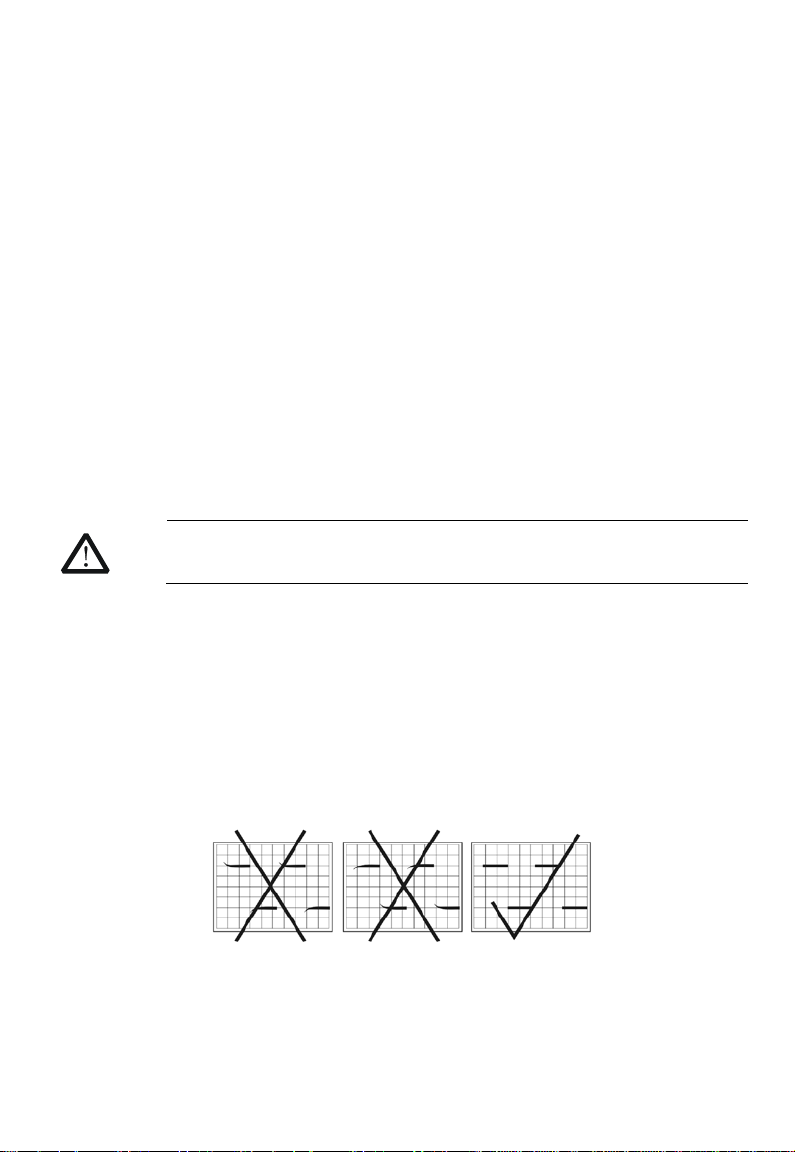
4. Compensation Adjustment
Connect the probe to the oscilloscope, and input a 200Hz square wave to the probe tip.
After that adjust the oscilloscope controls to display a few cycles of the waveform.
Adjust the trimmer located in the BNC plug for a flat topped square wave.
Illustration of 200Hz square wave adjustment
-7-
Page 4
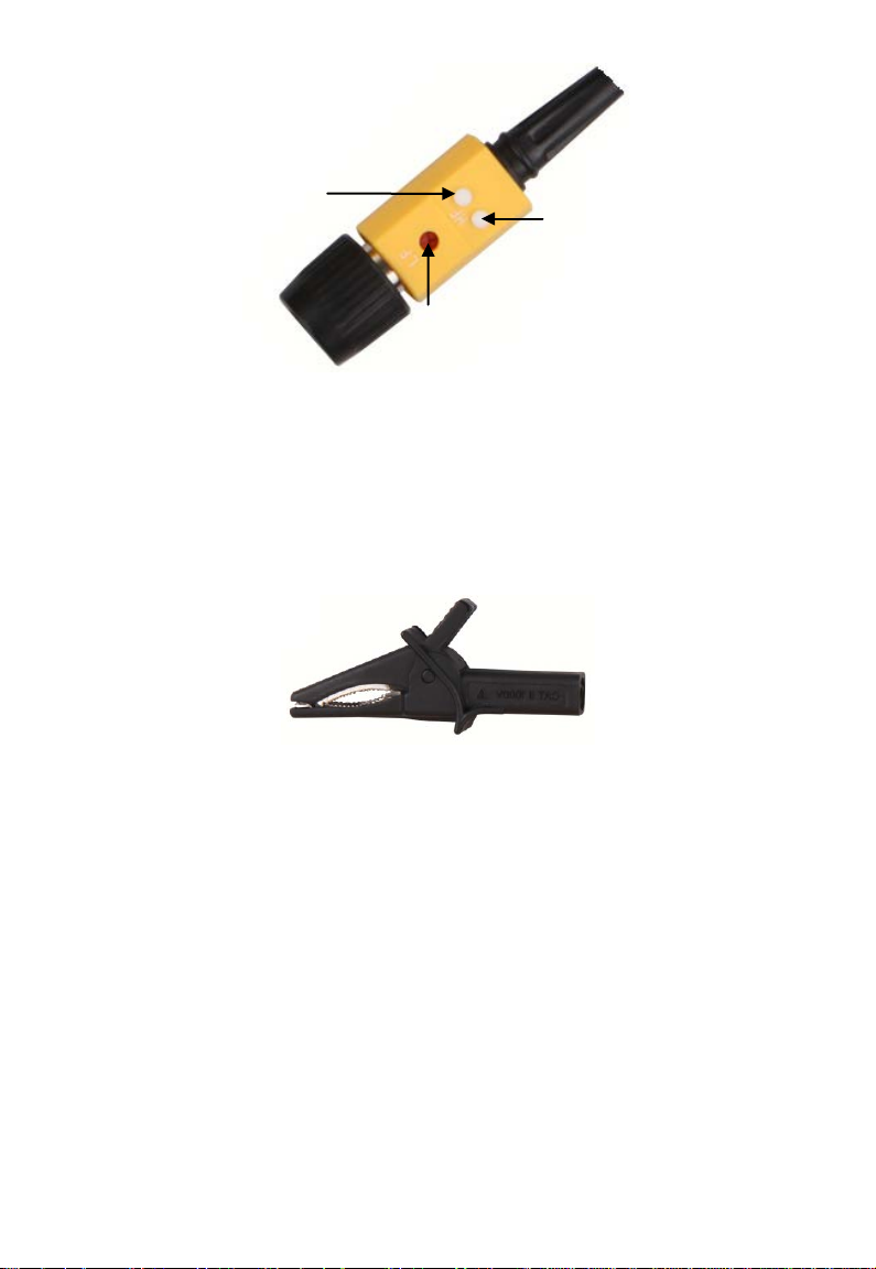
Adjust the frequency
response of the probe to
match your oscilloscope by
the adjust bar attached only.
Hole 2.
for 200kHz Square
Wave Adjustment
Hole 1.
for 200Hz Square Wave Adjustment
Hole 3.
for Bandwidth
Adjustment
CAUTION
1) Please use function signal generator to output 20 Vp-p, 200 Hz square waveform.
2) Non-professionals do not adjust the Hole 2 and Hole 3.
3) This product is already adjusting Hole 2 and Hole 3. Please feel free to operation.
4) Use the adjust bar attac h ed on ly.
5) When the measuring frequency was 40MHz up, you must replace the long earth
lead with the Alligator Clip (BP-276N-D) to obtain a best earth and the best
frequency response.
For 40MHz up
Measuring Frequency
5. Warning
1) Do not attempt to take the ground of test equipment away from the ground
terminal.
The ground connection is critical to the safety operation of the probe. Failure to
make this connection may result in personal injury or damage to the probe or
oscilloscope. You must be sure to connect the ground before the probe tip comes
into contacting with the high voltage. And the ground connection must not be
removed until the probe tip has been taken away from the high voltage source.
2) Do not connect the ground clip to the high voltage source or the probe tip to the
ground for any reason.
3) Before turning the high voltage on, make sure that no part of your body is in
contact with the device.
4) Remembering that the voltage being measured is 1000 times greater than the
-8-
Page 5

voltmeter reading.
Voltage (dc+ac peak)
Frequency
5) Disconnect the probe tip from the high voltage source before removing the
ground clip.
6. Cleaning
Clean only the exterior probe body and cables. Use a soft cotton cloth lightly moistened
with alcohol and water. Do not allow any porti on of the probe to submerge in the liquid.
Dry the probe thoroughly before measuring voltage.
Do not place the probe into the corrosive solvents or fumes as these will cause
deterioration to the probe and cables.
7. Voltage Derating Curve
RP1018H (18kV:3MHz / 300V:150MHz / 100V:1GHz)
-9-
Page 6
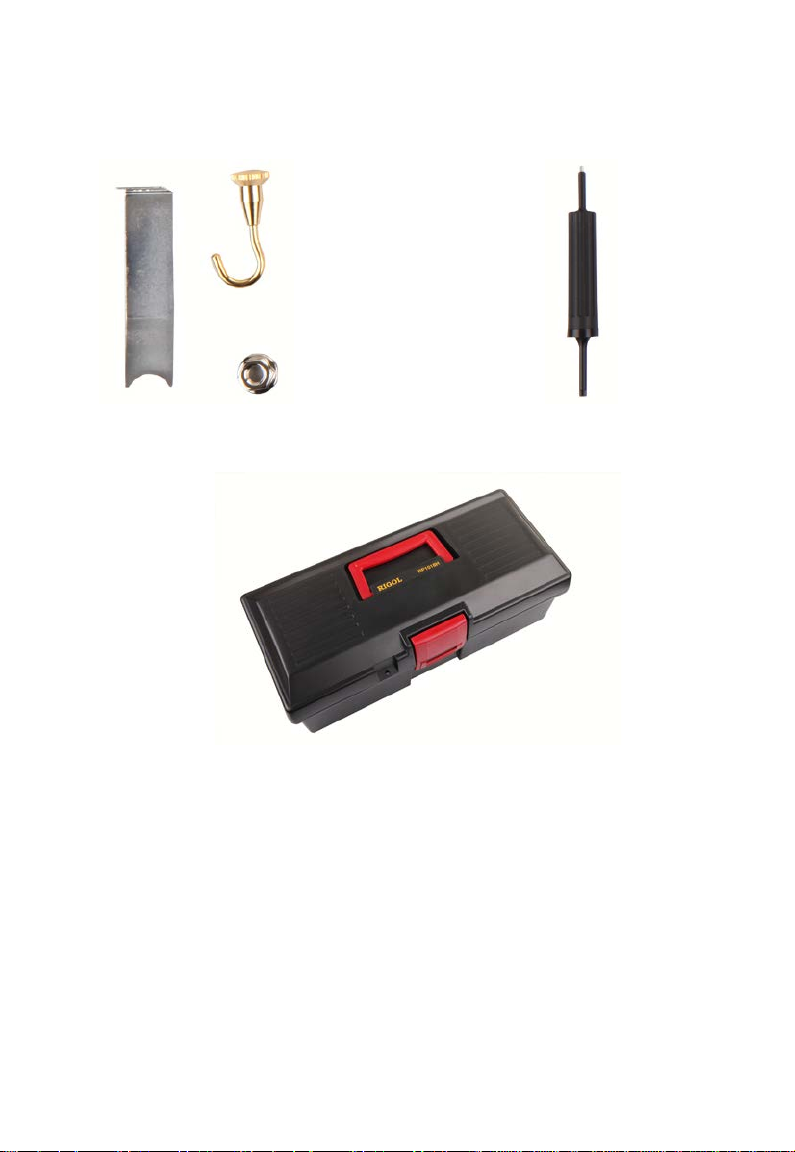
8. Accessories
Test CRT for H.V. Adjust bar
Carrying Box
Contact Us
If you have any problem or requirement when using our products or this manual,
please contact RIGOL.
E-mail: service@rigol.com
Websites: www.rigol.com
-10-
 Loading...