


RIGOL
Programming Guide
MSO8000 Series Dig ital Oscilloscope
Jul. 2019
RIGOL (SUZHOU) TECHNOLOGIES INC.


RIGOL
Guaranty and Declaration
Copyright
© 2019 RIGOL (SUZHOU) TECHNOLOGIES INC. All Ri g hts Reserved.
Trademark Information
RIGOL is a registered trademark of RIGOL (SUZHOU) TECHNOLOGIES INC.
Publication Number
PGA26103-1110
Software Version
00.00.00.04.00
Software upgrade might change or add product features. Please acquire the latest version of the manual
from RIGOL website or contact RIGOL to upgrade the software.
Notices
RIGOL products are covered by P.R.C. and foreign patents, issued and pending.
RIGOL reserves the right to modify or change parts of or all the specifications and pricing policies at
the company’s sole decision.
Information in this publication replaces all previously relea sed materials.
Information in this publication is subject to change without notice.
RIGOL shall not be liable for either incidental or consequential losses in connection with the furnishing,
use, or performance of this manual, as well as any information contained.
Any part of this document is forbidden to be copied, photocopied, or rearranged without prior written
approval of RIGOL.
Product Certification
RIGOL guarantees that this product conforms to the national and industrial standards in China as well as
the ISO9001:2015 standard a nd the ISO14001:2015 standard. Other international standard conformance
certifications are in progress.
Contact Us
If you have any problem or requirement when using our products o r this manual, please contact RIGOL.
E-mail: service@rigol.com
Website: www.rigol.com
MSO8000 Programming Guide I

RIGOL
Max.
Bandwidth
No. of
Channels
No. of Function/Arbitrary
Channels
16 (Required to purchase
the probe)
16 (Required to purchase
the probe)
16 (Required to purchase
the probe)
Tip
RIGOL
Document Overview
This manual is your guide to programming RIGOL MSO8000 series digital oscilloscope. MSO8000 series
can communicate with the PC via the USB, LAN, or GPIB (requiring to work with RIGOL's US B -GPIB
interface converter) interface.
Main Topics in this Manual:
Chapter 1 SCPI Command Overview
This chapter introduces the syntax, symbols, paramet ers, and abbreviation rules of the SCPI commands.
Chapter 2 Command System
This chapter introduces the syntax, function, parameters, and descriptions of each command.
Chapter 3 Programming Examples
This chapter illustrates how to control the MSO8000 series digital oscilloscope by programming in Excel,
LabVIEW, Visual Basic, and Visual C+ +.
For the latest version of this manual, download it from the official website of
(www.rigol.com).
Format Conventions in this Manual:
1. Key
The key on the front panel is denoted by the format of "Key Name (Bold) + Text Box" in the manual.
For example, Utility denotes the "Utility" key.
2. Menu
The menu items are denoted by the format of "Menu Wo rd (Bold) + Char acter Shading". F or example,
System denotes the "System" menu item under Utility.
3. Operation Procedures:
"" denotes the next step of operation. For example, Utility System denotes that first press
Utility, and then press the System softkey.
Content Conventions in this Manual:
MSO8000 series includes the following models. Unless otherw ise specified, this manual takes MSO8104 as
an example to illustrate the functions and operation methods of MSO8000 series.
Model
Analog
Analog
Waveform Generator
No. of Digital Channels
MSO8064 600 MHz 4 2 (Opt.)
MSO8104 1 GHz 4 2 (Opt.)
MSO8204 2 GHz 4 2 (Opt.)
II MSO8000 Programming Guide

Contents RIGOL
Contents
Guaranty and Declaration ......................................................................................................... I
Document Overview ................................................................................................................. II
Chapter 1 SCPI Command Overview .................................................................................. 1-1
Syntax ..................................................................................................................................... 1-1
Symbol Description ................................................................................................................... 1-1
Parameter Type ........................................................................................................................ 1-2
Command Abbreviation ............................................................................................................. 1-2
Chapter 2 Command System ............................................................................................... 2-1
:AUTOscale .............................................................................................................................. 2-2
:CLEar...................................................................................................................................... 2-2
:RUN ........................................................................................................................................ 2-2
:STOP ...................................................................................................................................... 2-2
:SINGle .................................................................................................................................... 2-3
:TFORce ................................................................................................................................... 2-3
:ACQuire Commands ................................................................................................................. 2-4
:ACQuire:AVERages ............................................................................................................ 2-4
:ACQuire:MDEPth ............................................................................................................... 2-4
:ACQuire:TYPE ................................................................................................................... 2-5
:ACQuire:SRATe? ................................................................................................................ 2-6
:ACQuire:LA:SRATe? ........................................................................................................... 2-6
:ACQuire:LA:MDEPth? ........................................................................................................ 2-6
:ACQuire:AALias ................................................................................................................. 2-6
:BUS<n> Commands ................................................................................................................ 2-7
:BUS<n>:MODE ................................................................................................................ 2-7
:BUS<n>:DISPlay .............................................................................................................. 2-8
:BUS<n>:FORMat .............................................................................................................. 2-8
:BUS<n>:EVENt ................................................................................................................ 2-8
:BUS<n>:EVENt:FORMat .................................................................................................... 2-9
:BUS<n>:EVENt:VIEW ....................................................................................................... 2-9
:BUS<n>:LABel ................................................................................................................. 2-9
:BUS<n>:DATA? .............................................................................................................. 2-10
:BUS<n>:EEXPort ............................................................................................................ 2-10
:BUS<n>:POSition ........................................................................................................... 2-11
:BUS<n>:THReshold ........................................................................................................ 2-11
:BUS<n>:PARallel ............................................................................................................ 2-12
:BUS<n>:RS232 (Option) ................................................................................................. 2-16
:BUS<n>:IIC (Option) ...................................................................................................... 2-21
:BUS<n>:SPI (Option) ..................................................................................................... 2-23
:BUS<n>:CAN (Option) .................................................................................................... 2-29
:BUS<n>:FLEXray (Option) .............................................................................................. 2-31
:BUS<n>:LIN (Option) ..................................................................................................... 2-33
:BUS<n>:IIS (Opt ion) ...................................................................................................... 2-35
:BUS<n>:M1553 (Option) ................................................................................................ 2-38
:CHANnel<n> Commands ....................................................................................................... 2-39
:CHANnel<n>:BWLimit ..................................................................................................... 2-39
:CHANnel<n>:COUPling ................................................................................................... 2-40
:CHANnel<n>:DISPlay ..................................................................................................... 2-40
:CHANnel<n>:INVert ....................................................................................................... 2-40
:CHANnel<n>:OFFSet ...................................................................................................... 2-41
:CHANnel<n>:TCALibrate ................................................................................................. 2-41
:CHANnel<n>:SCALe ....................................................................................................... 2-42
:CHANnel<n>:IMPedance ................................................................................................. 2-42
:CHANnel<n>:CSTart ....................................................................................................... 2-43
:CHANnel<n>:PROBe ....................................................................................................... 2-43
MSO8000 Programming Guide III

RIGOL Contents
:CHANnel<n>:PROBe:DELay ............................................................................................. 2-43
:CHANnel<n>:PROBe:BIAS ............................................................................................... 2-44
:CHANnel<n>:UNITs ........................................................................................................ 2-44
:CHANnel<n>:VERNier ..................................................................................................... 2-44
:CLOCk Commands ................................................................................................................. 2-46
:CLOCk:METHod ............................................................................................................... 2-46
:CLOCk:TYPE.................................................................................................................... 2-46
:CLOCk:RATE ................................................................................................................... 2-47
:CLOCk:PLL:ORDer ........................................................................................................... 2-47
:CLOCk:PLL:BW ................................................................................................................ 2-47
:CLOCk:EXTChan .............................................................................................................. 2-48
:COUNter Commands .............................................................................................................. 2-49
:COUNter:CURRent? ......................................................................................................... 2-49
:COUNter:CURRent? ......................................................................................................... 2-49
:COUNter:ENABle ............................................................................................................. 2-49
:COUNter:SOURce ............................................................................................................ 2-49
:COUNter:MODE ............................................................................................................... 2-50
:COUNter:NDIGits............................................................................................................. 2-50
:COUNter:TOTalize:ENABle ................................................................................................ 2-50
:COUNter:TOTalize:CLEar .................................................................................................. 2-51
:CURSor Commands ................................................................................................................ 2-52
:CURSor:MODE ................................................................................................................ 2-53
:CURSor:MANual .............................................................................................................. 2-54
:CURSor:TRACk ................................................................................................................ 2-60
:CURSor:XY ...................................................................................................................... 2-65
:DISPlay Commands ................................................................................................................ 2-68
:DISPlay:CLEar ................................................................................................................. 2-68
:DISPlay:TYPE .................................................................................................................. 2-68
:DISPlay:GRADing:TIME ................................................................................................... 2-69
:DISPlay:WBRightness ...................................................................................................... 2-69
:DISPlay:GRID ................................................................................................................. 2-69
:DISPlay:GBRightness ....................................................................................................... 2-70
:DISPlay:DATA? ................................................................................................................ 2-70
:DISPlay:RULers ............................................................................................................... 2-70
:DISPlay:COLor ................................................................................................................ 2-71
:DVM Commands .................................................................................................................... 2-72
:DVM:CURRent? ............................................................................................................... 2-72
:DVM:ENABle ................................................................................................................... 2-72
:DVM:SOURce .................................................................................................................. 2-72
:DVM:MODE ..................................................................................................................... 2-73
:EYE Commands ..................................................................................................................... 2-74
:EYE:ENABle .................................................................................................................... 2-74
:EYE:SOURce ................................................................................................................... 2-74
:EYE:MEASure:ENABle ...................................................................................................... 2-75
:EYE:MEASure:ITEM ......................................................................................................... 2-75
:HISTogram Commands ........................................................................................................... 2-76
:HISTogram:DISPlay ......................................................................................................... 2-76
:HISTogram:TYPE ............................................................................................................. 2-76
:HISTogram:SOURce ......................................................................................................... 2-77
:HISTogram:SIZE.............................................................................................................. 2-77
:HISTogram:STATic ........................................................................................................... 2-77
:HISTogram:RESet ............................................................................................................ 2-78
:HISTogram:BLIMit ........................................................................................................... 2-78
:HISTogram:LLIMit ........................................................................................................... 2-78
:HISTogram:RLIMit........................................................................................................... 2-78
:HISTogram:TLIMit ........................................................................................................... 2-79
IEEE488.2 Common Commands ............................................................................................... 2-80
*CLS ................................................................................................................................ 2-80
IV MSO8000 Programming Guide

Contents RIGOL
*ESE ............................................................................................................................... 2-80
*ESR? ............................................................................................................................. 2-80
*IDN? ............................................................................................................................. 2-81
*OPC ............................................................................................................................... 2-81
*SAV ............................................................................................................................... 2-81
*RCL ............................................................................................................................... 2-81
*RST ............................................................................................................................... 2-81
*SRE ............................................................................................................................... 2-82
*STB? ............................................................................................................................. 2-82
*TST? ............................................................................................................................. 2-82
*WAI ............................................................................................................................... 2-82
:JITTer Commands .................................................................................................................. 2-83
:JITTer:ENABle ................................................................................................................. 2-83
:JITTer:SOURce ............................................................................................................... 2-83
:JITTer:HISTogram:APPLy ................................................................................................. 2-84
:JITTer:TRENd:APPLy ....................................................................................................... 2-84
:JITTer:MEASure:TYPE ..................................................................................................... 2-84
:JITTer:MEASure:ITEM ..................................................................................................... 2-85
:JITTer:MEASure:STATistic:ITEM ....................................................................................... 2-85
:JITTer:MEASure:ENABle .................................................................................................. 2-85
:JITTer:SLOPe .................................................................................................................. 2-86
:LA Commands ....................................................................................................................... 2-87
:LA:STATe ........................................................................................................................ 2-87
:LA:ACTive....................................................................................................................... 2-88
:LA:AUTOsort ................................................................................................................... 2-88
:LA:DELete ...................................................................................................................... 2-88
:LA:DIGital:DISPlay .......................................................................................................... 2-89
:LA:DIGital:POSition ......................................................................................................... 2-89
:LA:DIGital:LABel ............................................................................................................. 2-90
:LA:POD<n>:DISPlay ....................................................................................................... 2-90
:LA:DISPlay ..................................................................................................................... 2-90
:LA:POD<n>:THReshold ................................................................................................... 2-91
:LA:SIZE .......................................................................................................................... 2-91
:LA:TCALibrate ................................................................................................................. 2-92
:LA:GROup:APPend .......................................................................................................... 2-92
:LAN Commands ..................................................................................................................... 2-93
:LAN:DHCP ...................................................................................................................... 2-93
:LAN:AUToip .................................................................................................................... 2-94
:LAN:GATeway ................................................................................................................. 2-94
:LAN:DNS ........................................................................................................................ 2-94
:LAN:MAC? ...................................................................................................................... 2-95
:LAN:DSErver? ................................................................................................................. 2-95
:LAN:MANual ................................................................................................................... 2-95
:LAN:IPADdress ............................................................................................................... 2-96
:LAN:SMASk .................................................................................................................... 2-96
:LAN:STATus? .................................................................................................................. 2-96
:LAN:VISA? ...................................................................................................................... 2-97
:LAN:MDNS ..................................................................................................................... 2-97
:LAN:HOST:NAME ............................................................................................................ 2-97
:LAN:DESCription ............................................................................................................. 2-97
:LAN:APPLy ...................................................................................................................... 2-98
:MASK Commands .................................................................................................................. 2-99
:MASK:ENABle ................................................................................................................. 2-99
:MASK:SOURce ................................................................................................................ 2-99
:MASK:OPERate ............................................................................................................. 2-100
:MASK:MDISplay ............................................................................................................ 2-100
:MASK:X ........................................................................................................................ 2-101
:MASK:Y ........................................................................................................................ 2-101
MSO8000 Programming Guide V

RIGOL Contents
:MASK:CREate ................................................................................................................ 2-101
:MASK:RESet .................................................................................................................. 2-101
:MATH<n> Commands .......................................................................................................... 2-102
:MATH<n>:DISPlay ........................................................................................................ 2-103
:MATH<n>:OPERator ..................................................................................................... 2-103
:MATH<n>:SOURce1 ...................................................................................................... 2-104
:MATH<n>:SOURce2 ...................................................................................................... 2-104
:MATH<n>:LSOUrce1 ..................................................................................................... 2-104
:MATH<n>:LSOUrce2 ..................................................................................................... 2-105
:MATH<n>:SCALe .......................................................................................................... 2-105
:MATH<n>:OFFSet ......................................................................................................... 2-106
:MATH<n>:INVert .......................................................................................................... 2-106
:MATH<n>:RESet ........................................................................................................... 2-106
:MATH<n>:FFT:SOURce ................................................................................................. 2-107
:MATH<n>:FFT:WINDow ................................................................................................ 2-107
:MATH<n>:FFT:UNIT ..................................................................................................... 2-107
:MATH<n>:FFT:SCALe .................................................................................................... 2-108
:MATH<n>:FFT:OFFSet .................................................................................................. 2-108
:MATH<n>:FFT:HSCale ................................................................................................... 2-108
:MATH<n>:FFT:HCENter ................................................................................................. 2-109
:MATH<n>:FFT:FREQuency:STARt .................................................................................. 2-109
:MATH<n>:FFT:FREQuency:END ..................................................................................... 2-109
:MATH<n>:FFT:SEARch:ENABle ...................................................................................... 2-110
:MATH<n>:FFT:SEARch:NUM .......................................................................................... 2-110
:MATH<n>:FFT:SEARch:THReshold ................................................................................. 2-110
:MATH<n>:FFT:SEARch:EXCursion .................................................................................. 2-111
:MATH<n>:FFT:SEARch:ORDer ....................................................................................... 2-111
:MATH<n>:FILTer:TYPE .................................................................................................. 2-111
:MATH<n>:FILTer:W1 .................................................................................................... 2-112
:MATH<n>:FILTer:W2 .................................................................................................... 2-113
:MATH<n>:SENSitivity .................................................................................................... 2-113
:MATH<n>:DISTance...................................................................................................... 2-113
:MATH<n>:THReshold1 .................................................................................................. 2-114
:MATH<n>:THReshold2 .................................................................................................. 2-114
:MATH<n>:THReshold3 .................................................................................................. 2-115
:MATH<n>:THReshold4 .................................................................................................. 2-115
:MEASure Commands ............................................................................................................ 2-116
:MEASure:SOURce .......................................................................................................... 2-116
:MEASure:COUNter:ENABle ............................................................................................. 2-117
:MEASure:COUNter:SOURce ............................................................................................ 2-117
:MEASure:COUNter:VALue? ............................................................................................. 2-118
:MEASure:CLEar ............................................................................................................. 2-118
:MEASure:THReshold:SOURce ......................................................................................... 2-118
:MEASure:THReshold:DEFault ......................................................................................... 2-118
:MEASure:MODE ............................................................................................................ 2-118
:MEASure:AMSource ....................................................................................................... 2-119
:MEASure:SETup:MAX ..................................................................................................... 2-119
:MEASure:SETup:MID ..................................................................................................... 2-120
:MEASure:SETup:MIN ..................................................................................................... 2-120
:MEASure:SETup:PSA ...................................................................................................... 2-120
:MEASure:SETup:PSB ...................................................................................................... 2-121
:MEASure:SETup:DSA ..................................................................................................... 2-121
:MEASure:SETup:DSB ..................................................................................................... 2-122
:MEASure:STATistic:DISPlay ............................................................................................ 2-122
:MEASure:STATistic:RESet ............................................................................................... 2-122
:MEASure:STATistic:ITEM ................................................................................................ 2-122
:MEASure:ITEM .............................................................................................................. 2-123
:MEASure:AREA .............................................................................................................. 2-124
VI MSO8000 Programming Guide

Contents RIGOL
:MEASure:CREGion:CAX ................................................................................................. 2-124
:MEASure:CREGion:CBX ................................................................................................. 2-125
:MEASure:CATegory ....................................................................................................... 2-125
:POWer Commands ............................................................................................................... 2-126
:POWer:TYPE ................................................................................................................. 2-126
:POWer:CURRentsource.................................................................................................. 2-126
:POWer:VOLTagesource .................................................................................................. 2-127
:POWer:QUALity:FREQREFerence .................................................................................... 2-127
:POWer:REFLevel:METHod ............................................................................................. 2-127
:POWer:REFLevel:PERCent:HIGH .................................................................................... 2-128
:POWer:REFLevel:PERCent:LOW ..................................................................................... 2-128
:POWer:REFLevel:PERCent:MID ...................................................................................... 2-128
:Quick Command .................................................................................................................. 2-129
:Quick:OPERation ........................................................................................................... 2-129
:RECord Commands .............................................................................................................. 2-130
:RECord:ENABle ............................................................................................................. 2-130
:RECord:STARt ............................................................................................................... 2-130
:RECord:PLAY ................................................................................................................ 2-131
:RECord:CURRent .......................................................................................................... 2-131
:RECord:FRAMes ............................................................................................................ 2-131
:REFerence Commands ......................................................................................................... 2-132
:REFerence:DISPlay ....................................................................................................... 2-132
:REFerence:SOURce ....................................................................................................... 2-132
:REFerence:VSCale ......................................................................................................... 2-133
:REFerence:VOFFset ....................................................................................................... 2-133
:REFerence:RESet .......................................................................................................... 2-134
:REFerence:CURRent ...................................................................................................... 2-134
:REFerence:SAVE ........................................................................................................... 2-134
:REFerence:COLor .......................................................................................................... 2-134
:REFerence:LABel:ENABle ............................................................................................... 2-135
:REFerence:LABel:CONTent ............................................................................................. 2-135
:SAVE and :Load Commands ................................................................................................. 2-136
:SAVE:CSV ..................................................................................................................... 2-136
:SAVE:CSV:LENGth ......................................................................................................... 2-136
:SAVE:FORMat ............................................................................................................... 2-137
:SAVE:IMAGe ................................................................................................................. 2-137
:SAVE:IMAGe:TYPE ........................................................................................................ 2-137
:SAVE:IMAGe:INVert ...................................................................................................... 2-138
:SAVE:IMAGe:COLor ....................................................................................................... 2-138
:SAVE:SETup.................................................................................................................. 2-138
:SAVE:WAVeform ........................................................................................................... 2-139
:SAVE:STATus? .............................................................................................................. 2-139
:LOAD:SETup ................................................................................................................. 2-139
:SEARch Commands ............................................................................................................. 2-140
:SEARch:STATe .............................................................................................................. 2-140
:SEARch:MODE .............................................................................................................. 2-141
:SEARch:EVENt .............................................................................................................. 2-141
:SEARch:EDGE:SLOPe .................................................................................................... 2-141
:SEARch:EDGE:SOURce .................................................................................................. 2-142
:SEARch:PULSe:POLarity ................................................................................................ 2-142
:SEARch:PULSe:QUALifier ............................................................................................... 2-142
:SEARch:PULSe:SOURce ................................................................................................. 2-143
:SEARch:RUNT:POLarity ................................................................................................. 2-143
:SEARch:RUNT:QUALifier ................................................................................................ 2-143
:SEARch:RUNT:SOURce .................................................................................................. 2-144
:SEARch:SLOPe:POLarity ................................................................................................ 2-144
:SEARch:SLOPe:QUALifier ............................................................................................... 2-145
:SEARch:SLOPe:SOURce ................................................................................................. 2-145
MSO8000 Programming Guide VII

RIGOL Contents
[:SOURce[<n>]] Commands ................................................................................................. 2-146
[:SOURce[<n>]]:FREQuency[:FIXed] .............................................................................. 2-147
[:SOURce[<n>]]:PHASe[:ADJust] .................................................................................... 2-147
[:SOURce[<n>]]:PHASe:INITiate .................................................................................... 2-148
[:SOURce[<n>]]:FUNCtion[:SHAPe] ................................................................................ 2-148
[:SOURce[<n>]]:FUNCtion:RAMP:SYMMetry .................................................................... 2-149
[:SOURce[<n>]]:VOLTage[:LEVel][:IMMediate][:AMPLitude] ............................................. 2-149
[:SOURce[<n>]]:VOLTage[:LEVel][:IMMediate]:OFFSet .................................................... 2-150
[:SOURce[<n>]]:PULSe:DCYCle ...................................................................................... 2-150
[:SOURce[<n>]]:MOD:TYPE ........................................................................................... 2-151
[:SOURce[<n>]]:MOD:AM[:DEPTh] ................................................................................. 2-152
[:SOURce[<n>]]:MOD:AM:INTernal:FREQuency ............................................................... 2-152
[:SOURce[<n>]]:MOD:FM:INTernal:FREQuency ............................................................... 2-152
[:SOURce[<n>]]:MOD:AM:INTernal:FUNCtion .................................................................. 2-153
[:SOURce[<n>]]:MOD:FM:INTernal:FUNCtion .................................................................. 2-153
[:SOURce[<n>]]:MOD:FM[:DEVIation] ............................................................................ 2-154
[:SOURce[<n>]]:SWEep:TYPE ........................................................................................ 2-154
[:SOURce[<n>]]:SWEep:STIMe ...................................................................................... 2-155
[:SOURce[<n>]]:SWEep:BTIMe ...................................................................................... 2-155
[:SOURce[<n>]]:BURSt:TYPE ......................................................................................... 2-155
[:SOURce[<n>]]:BURSt:CYCLes ...................................................................................... 2-156
[:SOURce[<n>]]:BURSt:DELay........................................................................................ 2-156
[:SOURce[<n>]]:APPLy? ................................................................................................. 2-157
[:SOURce[<n>]]:APPLy:NOISe ........................................................................................ 2-157
[:SOURce[<n>]]:APPLy:PULSe ........................................................................................ 2-157
[:SOURce[<n>]]:APPLy:RAMP ......................................................................................... 2-157
[:SOURce[<n>]]:APPLy:SINusoid .................................................................................... 2-157
[:SOURce[<n>]]:APPLy:SQUare ...................................................................................... 2-157
[:SOURce[<n>]]:APPLy:USER ......................................................................................... 2-157
[:SOURce[<n>]]:OUTPut[<n>][:STATe] .......................................................................... 2-158
[:SOURce[<n>]]:OUTPut[<n>]:IMPedance ..................................................................... 2-159
:SYSTem Commands ............................................................................................................. 2-160
:SYSTem:AOUTput .......................................................................................................... 2-161
:SYSTem:AUTClear ......................................................................................................... 2-161
:SYSTem:AUTOscale ....................................................................................................... 2-161
:SYSTem:BEEPer ............................................................................................................ 2-162
:SYSTem:DATE ............................................................................................................... 2-162
:SYSTem:ERRor[:NEXT]? ................................................................................................. 2-162
:SYSTem:GAMount? ........................................................................................................ 2-162
:SYSTem:RCLock ............................................................................................................ 2-163
:SYSTem:GPIB ................................................................................................................ 2-163
:SYSTem:KEY:PRESs ....................................................................................................... 2-163
:SYSTem:KEY:INCRease .................................................................................................. 2-165
:SYSTem:KEY:DECRease ................................................................................................. 2-165
:SYSTem:LANGuage ........................................................................................................ 2-165
:SYSTem:PON ................................................................................................................ 2-166
:SYSTem:PSTatus ........................................................................................................... 2-166
:SYSTem:OPTion:INSTall ................................................................................................. 2-166
:SYSTem:OPTion:UNINstall ............................................................................................. 2-167
:SYSTem:OPTion:STATus? ............................................................................................... 2-167
:SYSTem:PWDClear ........................................................................................................ 2-168
:SYSTem:RAMount? ........................................................................................................ 2-168
:SYSTem:RESet .............................................................................................................. 2-168
:SYSTem:SETup .............................................................................................................. 2-168
:SYSTem:SSAVEr:TIME ................................................................................................... 2-168
:SYSTem:TIME ............................................................................................................... 2-169
:SYSTem:LOCKed ........................................................................................................... 2-169
:SYSTem:MODules? ........................................................................................................ 2-169
VIII MSO8000 Programming Guide

Contents RIGOL
:TIMebase Commands .......................................................................................................... 2-170
:TIMebase:DELay:ENABle ............................................................................................... 2-170
:TIMebase:DELay:OFFSet ............................................................................................... 2-170
:TIMebase:DELay:SCALe ................................................................................................ 2-171
:TIMebase[:MAIN]:OFFSet.............................................................................................. 2-171
:TIMebase[:MAIN]:SCALe ............................................................................................... 2-172
:TIMebase:MODE ........................................................................................................... 2-172
:TIMebase:HREFerence:MODE ........................................................................................ 2-172
:TIMebase:HREFerence:POSition ..................................................................................... 2-173
:TIMebase:VERNier ........................................................................................................ 2-173
:TRIGger Commands ............................................................................................................ 2-174
:TRIGger:MODE ............................................................................................................. 2-175
:TRIGger:COUPling ........................................................................................................ 2-175
:TRIGger:STATus? .......................................................................................................... 2-175
:TRIGger:SWEep ............................................................................................................ 2-176
:TRIGger:HOLDoff ......................................................................................................... 2-176
:TRIGger:NREJect .......................................................................................................... 2-177
:TRIGger:EDGE .............................................................................................................. 2-177
:TRIGger:PULSe ............................................................................................................. 2-179
:TRIGger:SLOPe ............................................................................................................. 2-181
:TRIGger:VIDeo ............................................................................................................. 2-184
:TRIGger:PATTern .......................................................................................................... 2-187
:TRIGger:DURation ........................................................................................................ 2-189
:TRIGger:TIMeout .......................................................................................................... 2-192
:TRIGger:RUNT ............................................................................................................. 2-194
:TRIGger:WINDows ....................................................................................................... 2-197
:TRIGger:DELay ............................................................................................................. 2-200
:TRIGger:SHOLd ............................................................................................................ 2-204
:TRIGger:NEDGe ............................................................................................................ 2-208
:TRIGger:RS232 (Option) ............................................................................................... 2-210
:TRIGger:IIC (Option) .................................................................................................... 2-213
:TRIGger:CAN (Option) .................................................................................................. 2-217
:TRIGger:SPI (Option) .................................................................................................... 2-220
:TRIGger:FLEXray (Option) ............................................................................................. 2-225
:TRIGger:IIS (Option) .................................................................................................... 2-227
:TRIGger:LIN (Option) ................................................................................................... 2-231
:TRIGger:M15 53 (Option) ............................................................................................... 2-234
:WAVeform Commands ......................................................................................................... 2-236
:WAVeform:SOURce ....................................................................................................... 2-237
:WAVeform:MODE .......................................................................................................... 2-238
:WAVeform:FORMat ....................................................................................................... 2-238
:WAVeform:POINts ......................................................................................................... 2-239
:WAVeform:DATA?.......................................................................................................... 2-239
:WAVeform:XINCrement? ............................................................................................... 2-240
:WAVeform:XORigin? ...................................................................................................... 2-240
:WAVeform:XREFerence? ................................................................................................ 2-240
:WAVeform:YINCrement? ............................................................................................... 2-241
:WAVeform:YORigin? ...................................................................................................... 2-241
:WAVeform:YREFerence? ................................................................................................ 2-241
:WAVeform:STARt .......................................................................................................... 2-242
:WAVeform:STOP ........................................................................................................... 2-242
:WAVeform:PREamble? ................................................................................................... 2-242
Chapter 3 Programming Examples ..................................................................................... 3-1
Programming Preparations ........................................................................................................ 3-2
Excel Programming Example...................................................................................................... 3-3
LabVIEW Programming Example ................................................................................................ 3-7
Visual Basic Programming Example .......................................................................................... 3-11
Visual C++ Programming Example ........................................................................................... 3-13
MSO8000 Programming Guide IX


Chapter 1 SCPI Command Overview RIGOL
Chapter 1 SCPI Command Overview
SCPI (Standard Commands for Programmable Instruments) is a standardized instrument programming
language that is built upon the existing standard IEEE 488.1 and IEEE 488.2 and conforms to various
standards, such as the floating point operation rule in IEEE 754 standard, ISO 646 7-bit coded character set
for information interchange (equivalent to ASCII programming). The SCPI commands provide a hierarchical
tree structure, and consist of multiple subsystems. Each command subsystem consists of one root keyword
and one or more sub-keywords.
Contents in this cha pter:
Syntax
Symbol Description
Parameter Type
Command Abbreviation
Syntax
The command line usually starts with a colon; the keywords are separated by colons, and following the
keywords are the parameter settings available. The command endi ng with a quotation mark indicates
querying a certain function. The keywords of the command and the first parameter is separated by a space.
For example,
:ACQuire:TYPE <type>
:ACQuire:TYPE?
ACQuire is the root keyword of the command, and TYPE is the second-level keyword. The command line
starts with a colon, and different levels of keywords are also separated by colons. <type> indicates a
settable parameter. The command ending with a quotation mark indicates querying a certain function. The
command keywords ":ACQuire:TYPE" and the parameter <type> are separated by a space.
In some commands with parameters, "," is often used to separate multiple parameters. For example,
:SYSTem:DATE <year>,<month>,<day>.
Symbol Description
The following symbols are not sent with the commands.
1. Braces { }
The contents enclosed in the braces are parameter options. Parameters are usually separated by the
vertical bar "|". When using the command, you must select one of the parameters.
2. Vertical Bar |
The vertical bar is used to separate multiple parameters. When using the command, you must select
one of the parameters.
3. Square Brackets [ ]
The contents in the square brackets can be omitted.
4. Angle Brackets < >
The parameter enclosed in the angle brackets must be replaced by an effective value.
MSO8000 Programming Guide 1-1

RIGOL Chapter 1 SCPI Command Overview
Parameter Type
1. Bool
The parameter can be set to ON, OFF, 1, or 0. For example,
:SYSTem:BEEPer <bool>
:SYSTem:BEEPer?
Wherein,
<bool> can be set to {{1|ON}|{0|OFF}}.
The query returns 1 or 0.
2. Discrete
The parameter can be any of the values listed. For example,
:ACQuire:TYPE <type>
:ACQuire:TYPE?
Wherein,
<type> can be set to NORMal, AVERages, or PEAK.
The query returns NORM, AVER, or PEAK.
3. Integer
Unless otherwise specified, the parameter can be any integer (NR1 format) within the effective value
range.
Note: Do not set the parameter to a decimal, otherwise, errors will occur.
For example,
:DISPlay:GBRig htnes s <bri g htne ss >
:DISPlay:GBRightness?
Wherein, <brightness> can be set to an integer ranging from 1 to 100.
The query returns a n i nteger ranging from 1 to 100.
4. Real
The parameter can be any real number within the effective value range, and this command accepts
parameter input in decimal (NR2 format) and scientific notation (NR3 format). For example,
:TRIGger:TIMeout:TIME <time>
:TRIGger:TIMeout:TIME?
Wherein, <time> can be set to any real number ranging from 1.6E-8 (i.g. 16 ns) to 1E+1 (i.g. 10 s).
The query returns a real number in scientific notation.
5. ASCII String
The parameter can be the combinations of ASCII characters.
For example,
:SYSTem:OPTion:INSTall <license>
Wherein, <license> can be set to
MSO8000-PWR@3AEBC07E6C31F82B78A1C401DC2E3AC2CC9431B57F60D1E1CB712F8682C93609A6
05F8577BFDE920373062BE226289A27C134E2C91BF80CB00F8011AC181FD40.
Command Abbreviation
All the commands are case-insensitive. They can all be in upper case or in lower case. If abbreviation is
used, you must input a ll the capital letters in the command. For example,
:DISPlay:GBRightness?
can be abbreviated as
:DISP:GBR?
1-2 MSO8000 Programming Guide

Chapter 2 Command System RIGOL
Chapter 2 Command System
This chapter introduces the syntax, functions, parameters, and usage of each MSO8000 command. For this
oscilloscope, only CH1 is enabled by default.
Contents in this chapter:
:AUToscale
:CLEar
:RUN
:STOP
:SINGle
:TFORce
:ACQuire Commands
:BUS<n> Commands
:CHANnel<n> Commands
:CLOCk Commands
:COUNter Commands
:CURSor Commands
:DISPlay Commands
:DVM Commands
:EYE Commands
:HISTogram Commands
IEEE488.2 Common Commands
:JITTer Commands
:LA Commands
:LAN Commands
:MASK Commands
:MATH<n> Commands
:MEASure Commands
:POWer Commands
:Quick Command
:RECord Commands
:REFerence Commands
:SAVE and :Load Commands
:SEARch Commands
[:SOURce[<n>]] Commands
:SYSTem Commands
:TIMebase Commands
:TRIGger Commands
MSO8000 Programming Guide 2-1

RIGOL Chapter 2 Command System
Syntax
:AUToscale
the front panel.
forced to be disabled.
Syntax
:CLEar
key on the front panel.
:STOP
panel.
is disabled.
:WAVeform Commands
Note:
1. Unless otherwise specified, the descriptions in this manual all take MSO8104 as an example.
2. For the par ameter setting command (tim e, frequency, amplitude, etc.), the digital osci lloscope can only
recognize the numbers, unable to recognize the unit sent together with them. The unit of the
parameter is a default o ne. F or the default units of v arious parameters, r efer to the d escriptions f or the
specified command.
:AUToscale
Description Enables the wavef orm auto setting function. The oscilloscope will automatically adjust the
vertical scale, horizontal time base, and trigg er mode according to the input signal to
realize optimal waveform display . This command functions the same as the AUTO key on
Remarks When the AUTO function is disabled, this command is invalid. For details, refer
to :SYSTem:AUToscale.
When the pass/fail test is enabled, the AUTO function runs normally , but the pass/fail
test function is forced to be disabled.
When the waveform recording function is enabled or the recorded waveforms are
played back, the AUTO function runs normally, but the recording or playing function is
:CLEar
Description
Clears all the wavef or ms on the s creen . This command functions the same as the CLEAR
:RUN
:STOP
Syntax :RUN
Description The :RUN command starts the oscilloscope and the :STOP command stops the
oscilloscope. This command functions the sam e as the RUN/STOP key on the front
Remarks
When the waveform r ecording function is enabled, the RUN/STOP key on the front panel
2-2 MSO8000 Programming Guide

Chapter 2 Command System RIGOL
Syntax
:SINGle
the :TRIGger:SWEep SINGle command.
force.
Syntax
:TFORce
the same as the FORCE key in the trigger control area of the front panel.
:SINGle
Description Sets the trigger mode of the oscilloscope to "Single". This command functions the same as
either of the following two operation: press SINGLE on the front panel; or send
Remarks In the single trigger mode, the oscilloscope performs a single trigger when the trigger
conditions are met and then it stops.
When the waveform recording function is enabled or the recorded waveforms are
played back, this command is invalid.
For the single trigger, you can use the
:TFORce command to generate one trigger by
:TFORce
Description Generates a trigger signal forcibly. This command is only applicable to the normal and
single trigger modes (refer to the
:TRIGger:SWEep command). This command functions
MSO8000 Programming Guide 2-3

RIGOL Chapter 2 Command System
:ACQuire:AVERages?
Description
Sets or queries the number of averages in the average acquisition mode.
Name
Type
Range
Default
<count>
Integer
2n (n is an integer, and its range is from 1 to 16)
2
waveform to the waveform changes.
Format
:ACQuire:AVERages? /*The query returns 128.*/
:ACQuire:MDEPth?
points that can be stored through the sampling in a single trigger). The default unit is pts.
Name
Type
Range
Default
6|1e7|2.5e7|5e7|1e8|1.25e8|2.5e8|5e8}
:ACQuire Commands
The :ACQuire commands are used to set the memory depth of the oscilloscope, the acquisition mode, the
average times, as well as query the current sample rate.
Command List
:ACQuire:AVERages
:ACQuire:MDEPth
:ACQuire:TYPE
:ACQuire:SRATe?
:ACQuire:LA:SRATe?
:ACQuire:AALias
[1]
Note
omitted. You can refer to the complete introductions of the commands in the body of the text based on the keywords
listed here.
: In the "Command List" in this manual, the query commands and the parameters in the setting commands are
:ACQuire:AVERages
[1]
:
Syntax :ACQuire:AVERages <c ount>
Parameter
Remarks You can send the :ACQuire:TYPE command to set the acquisition mode.
In the average acquisition mode, greater number of averages can lower the noise
and increase the vertical resolution; but will also slow the response of the displayed
Return
Example
The query returns a n i nteger ranging from 2 to 65536.
:ACQuire:AVERages 128 /*Sets the average times to 128.*/
:ACQuire:MDEPth
Syntax :ACQuire:MDEPth <mdep>
Description Sets or queries the memory depth of the oscilloscope (i.g. the number of waveform
Parameter
<mdep>
{AUTO|1k|10k|100k|1M|10M|25M|50M|100M|1
25M|250M|500M|1000|10000|100000|1000000|
Discrete
10000000|25000000|50000000|100000000|125
000000|250000000|500000000|1e3|1e4|1e5|1e
2-4 MSO8000 Programming Guide
AUTO

Chapter 2 Command System RIGOL
four-channel is 125 M.
Format
:ACQuire:MDEPth? /*The query returns 1.000000E+6.*/
:ACQuire:TYPE?
Description
Sets or queries the acquisition mode of the oscilloscope.
Name
Type
Range
Default
<type>
Discrete
{NORMal|AVERages|PEAK|HRESolution}
NORMal
resolution. Greater nu mber o f a verages can lower the nois e an d in c rease th e vertical
digital converter is greater than the storage rate of the sample storage.
Format
:ACQuire:TYPE? /*The query returns AVER.*/
Remarks When "AUTO" is selected, the oscilloscope selects the memory depth automatically
according to the current sample rate.
The maximum memory depth for the single c hannel is 50 0 M; the maxi mum memory
depth for the dual-channel is 250 M; and the maximum memory depth for the
Return
Example
The query returns the memory depth in scientific notation.
:ACQuire:MDEPth 1M /*Sets the memory depth to 1M.*/
:ACQuire:TYPE
Syntax :ACQuire:TYPE <type>
Parameter
Remarks NORMal: In this mode, the oscilloscope samples the signal at a specified fixed time
interval to rebuild the waveform. For most of the waveforms, using this mode can
produce the optimal display effects.
AVERages: In this mode, the oscilloscope averages the waveforms from multiple
samples to reduce the random noise of the input signal and improve the vertical
resolution; while at the same time, it will slow the response of the displayed
waveform to the waveform changes.
PEAK: indicates the peak detection. In this mode, the oscilloscope samples the
maximum and minimum value of the signal at the fixed sampling interval to acquire
the signal envelope or the narrow pulses that might be lost. In this mode, signal
aliasing can be prevented, but the noise displayed would be larger.
HRESolution: the oscillo scope averages the neighbouring points of the sampled
waveform to reduce the random noise on the input signal and display smoother
waveform on the screen. This mode is usually used when the sample rate of the
Return
Example
The query returns NORM, AVER, PEAK, or HRES.
:ACQuire:TYPE AVERages /*Sets the acquisition mode to AVERages.*/
MSO8000 Programming Guide 2-5

RIGOL Chapter 2 Command System
Syntax
:ACQuire:SRATe?
Description
Queries the current sample rate. The default unit is Sa/s.
The formula below des cribes the relations hip among sample rate, memory depth, and
direction. For MSO8000, the number of grids in the hor izontal direction is 10.
Format
Example
:ACQuire:SRATe? /*The query returns 2.500000E+9.*/
Syntax
:ACQuire:LA:SRATe?
Description
Queries the current LA sample rate. The default unit is Sa/s.
Format
Example
:ACQuire:LA:SRATe? /*The query returns 1.250000E+9.*/
Syntax
:ACQuire:LA:MDEPth?
Description
Queries the current LA memory depth.
Format
Example
:ACQuire:LA:MDEPth? /*The query returns 1.250000E+4.*/
:ACQuire:AALias?
status of the anti-aliasing function.
Name
Type
Range
Default
<bool>
Bool
{{1|ON}|{0|OFF}}
0|OFF
Format
:ACQuire:AALias? /*The query returns 1.*/
:ACQuire:SRATe?
Remarks Sample rate indicates the frequency of the signal sampling, i.g. the number of
waveform points sampled per second.
waveform length:
memory depth = sample rate x waveform length
Wherein, the memory dep th is set by the
length is obtained by multiplying the horizontal time base (set by
:TIMebase[:MAIN]:SCALe command) by the number of grids in the horizontal
the
:ACQuire:MDEPth command. The wav eform
Return
The query returns the sample rate in scientific notation.
:ACQuire:LA:SRATe?
Return
The query returns the sample rate in scientific notation.
:ACQuire:LA:MDEPth?
Return
The query returns the memory depth in scientific notation.
:ACQuire:AALias
Syntax :ACQuire:AALias <bool>
Description Enables or disables the anti-aliasing function of the oscilloscope; or queries the on/off
Parameter
Return
Example
2-6 MSO8000 Programming Guide
The query returns 1 or 0.
:ACQuire:AALias ON /*Enables the anti-aliasing function.*/

Chapter 2 Command System RIGOL
:BUS<n>:MODE?
Description
Sets or queries the decoding type of the specified decoding bus.
Name
Type
Range
Default
<n>
Discrete
{1|2|3|4}
——
FLEXray|M1553}
installed, can the command is available.
Format
:BUS1:MODE? /*The query returns SPI.*/
:BUS<n> Commands
The : BUS<n> commands are used to execute the decoding-related settings and operations.
Command List:
:BUS<n>:MODE
:BUS<n>:DISPlay
:BUS<n>:FORMat
:BUS<n>:EVENt
:BUS<n>:EVENt:FORMat
:BUS<n>:EVENt:VIEW
:BUS<n>:LABel
:BUS<n>:DATA?
:BUS<n>:EEXPort
:BUS<n>:POSition
:BUS<n>:THReshold
:BUS<n>:PARallel
:BUS<n>:RS232 (Option)
:BUS<n>:IIC (Option)
:BUS<n>:SPI (Option)
:BUS<n>:CAN (Option)
:BUS<n>:FLEXray (Option)
:BUS<n>:LIN (Option)
:BUS<n>:IIS (Option)
:BUS<n>:M1553 (Option)
:BUS<n>:MODE
Syntax :BUS<n>:MODE <mode>
Parameter
<mode> Discrete
{PARallel|RS232|SPI|IIC|IIS|LIN|CAN|
Remarks Except P ARallel, all the other decodings are options. Only when the specified option is
Return
Example
MSO8000 Programming Guide 2-7
The query returns PAR, RS232, SPI, IIC, IIS, LIN , CAN, FLEX, or M1553.
:BUS1:MODE SPI /*Se ts the type of the decod ing bus to SPI.*/
PARallel

RIGOL Chapter 2 Command System
:BUS<n>:DISPlay?
the specified decoding bus.
Name
Type
Range
Default
<n>
Discrete
{1|2|3|4}
——
<bool>
Bool
{{1|ON}|{0|OFF}}
0|OFF
Format
:BUS1:DISPlay? /*The query returns 1.*/
:BUS<n>:FORMat?
Description
Sets or queries the display format of decoding data of the specified decoding bus.
Name
Type
Range
Default
<n>
Discrete
{1|2|3|4}
——
<fmt>
Discrete
{HEX|ASCii|DEC|BIN}
ASCii
Remarks
HEX indicates Hexadecimal; DEC indicates Decima l; BIN indicates Binary.
Format
:BUS1:FORMat? /*The query returns HEX.*/
:BUS<n>:EVENt?
status of the specified decoding bus event table.
Name
Type
Range
Default
<bool>
Bool
{{1|ON}|{0|OFF}}
0|OFF
Remarks
Before using the command, enable the specified decoding bus.
Format
:BUS1:EVENt? /*The query returns 1.*/
:BUS<n>:DISPlay
Syntax :BUS<n>:DISPlay <bool>
Description Enables or disables the specified decoding b us; or queries the on/off display status of
Parameter
Return
Example
The query returns 1 or 0.
:BUS1:DISPlay ON /*Enables the decoding bus.*/
:BUS<n>:FORMat
Syntax :BUS<n>:FORMat <fmt>
Parameter
Return
Example
The query returns HEX, ASC, DEC, or BIN.
:BUS1:FORMat HEX /*Sets the display format of the bus to HEX.*/
:BUS<n>:EVENt
Syntax :BUS<n>:EVENt <bool>
Description Enables or disables the event table of the specified decoding bus; or queries the on/off
Parameter
<n> Discrete {1|2|3|4} ——
Return
Example
2-8 MSO8000 Programming Guide
The query returns 1 or 0.
:BUS1:EVENt ON /*Enables the event table of the specified decoding bus.*/

Chapter 2 Command System RIGOL
:BUS<n>:EVENt:FORMat?
Description
Sets or queries the display format of the specified decoding bus event table.
Name
Type
Range
Default
<n>
Discrete
{1|2|3|4}
——
<format>
Discrete
{HEX|ASCii|DEC|BIN}
ASCii
Remarks
HEX indicates Hexadecimal; DEC indicates Decima l; BIN indicates Binary.
Format
:BUS1:EVENt:FORMat? /*The query returns HEX.*/
:BUS<n>:EVENt:VIEW?
Description
Sets or queries the data page of the specified decoding bus event table.
Name
Type
Range
Default
<n>
Discrete
{1|2|3|4}
——
<packet>
Discrete
{PACKets|DETails|PAYLoad}
PACKets
changed accordingly.
Format
:BUS1:EVENt:VIEW? /*The query returns DET.*/
:BUS<n>:LABel?
of the label of the specified decoding bus.
:BUS<n>:EVENt:FORMat
Syntax :BUS<n>:EVENt:FORMat <format>
Parameter
Return
Example
The query returns HEX, ASC, DEC, or BIN.
:BUS1:EVENt:FORMat HEX
/*Sets the display format of the specified decoding bus event table to HEX.*/
:BUS<n>:EVENt:VIEW
Syntax :BUS<n>:EVENt:VIEW <packet>
Parameter
Remarks
PACKets: displays time, data, and error information in the specified event table.
DETails: displays the detailed data of the specified row in the event table.
PAYLoad: displays all the data of the specified column in the event table.
When different views are selected, the export format of the data list will be
Return
Example
The query returns PACK, DET, or PAYL.
:BUS1:EVENt:VIEW DETails /*Sets the data page of the decoding bus event table
to DETails.*/
:BUS<n>:LABel
Syntax :BUS<n>:LABel <bool>
Description Enables or disables the label of the specified decoding bus; or queries the on/off status
MSO8000 Programming Guide 2-9

RIGOL Chapter 2 Command System
Name
Type
Range
Default
<n>
Discrete
{1|2|3|4}
——
<bool>
Bool
{{1|ON}|{0|OFF}}
0|OFF Remarks
Before using the command, enable the specified decoding bus.
Format
:BUS1:LABel? /*The query returns 1.*/
Syntax
:BUS<n>:DATA?
Description
Reads the data in the decoding event table.
Name
Type
Range
Default
<n>
Discrete
{1|2|3|4}
——
list.
Syntax
:BUS<n>:EEXPort
Description
Exports the decoding information in the specified decoding bus event table in CSV form.
Name
Type
Range
Default
<n>
Discrete
{1|2|3|4}
——
with the filename 123.csv.*/
Parameter
Return
Example
The query returns 1 or 0.
:BUS1:LABel ON /*Enables the label of the specified decoding bus.*/
:BUS<n>:DATA?
Parameter
Return
Format
The query returns the data in the decoding event table with the following formats .
#9000000072PAL,
Time,Data,,
-1us,0,,
-990.3ns,1,,
-503.2ns,0,,
9.2ns,1,,
497.2ns,0,
Wherein, "#9000000072" is the TMC data block header, which is followed by the data
in the event table. The 9-digit data following #9 in the data block header indicates
the number of bytes of the effective data. "PAL" indicates the decoding type. The
available decoding type can also be RS232, I2C, SPI, or CAN. The data are sep arated
by commas, and will automatically go to the next l ine according to the line length
limit in the decoding list. The data value is related to the numeral system that you
have set.
Note: You can save all the data (except TMC data block header and decoding type,
e.g. #9000000072PAL)
as the "*.csv" file and view the data in the form of a
:BUS<n>:EEXPort
Parameter
Example :BUS1:EEXPort C:/123.csv
/*Exports the decoding information in the bus event table to the local Disk C,
2-10 MSO8000 Programming Guide

Chapter 2 Command System RIGOL
:BUS<n>:POSition?
Description
Sets or queries the vertical position of the bus on the screen.
Name
Type
Range
Default
<n>
Discrete
{1|2|3|4}
——
channel offset
Format
:BUS1:POSition? /*The query returns 200.*/
:BUS<n>:THReshold? <typ e >
Description
Sets or queries the threshold of the specified decoding source.
Name
Type
Range
Default
<n>
Discrete
{1|2|3|4}
——
(5×VerticalScale–OFFSet)
SI|LIN|CAN|CANSub1}
For SPI decoding, only when the MOSI source is enabled, can you set the threshold.
Format
:BUS1:THReshold? PAL /*The query returns 2.400000E0.*/
:BUS<n>:POSition
Syntax :BUS<n>:POSition <pos>
Parameter
Related to the
Return
Example
<pos> Integer -167 to +217
The query returns a n i nteger ranging from -1 67 to +217.
:BUS1:POSition 200 /*Se ts the vertical position of the bus to 200.*/
:BUS<n>:THReshold
Syntax :BUS<n>:THReshold <value>,<type>
Parameter
<value> Real
<type> Discrete
Remarks For VerticalScale, refer to the :CHANnel<n>:SCALe command. For OFFSet, refer to
:CHANnel<n>:OFFSet command.
the
(-5×VerticalScale–OFFSet) to
{PAL|TX|RX|SCL|SDA|CS|CLK|MISO|MO
0
——
For RS232 decoding, only when the Rx source is enabled, can you set the threshold.
Return
The query returns the threshold of t he specified decod ing source in scient ific notation.
Example :BUS1:THReshold 2.4,PAL /*Sets the threshold of the PAL decoding source to 2.4 V.*/
MSO8000 Programming Guide 2-11

RIGOL Chapter 2 Command System
:BUS<n>:PARallel:CLK?
Description
Sets or queries the clock source of the Parallel decoding.
Name
Type
Range
Default
<n>
Discrete
{1|2|3|4}
——
OFF}
Format
D15, CHAN1, CHAN2, CHAN3, CHAN4, or OFF.
:BUS1:PARallel:CLK? /*The query returns D0.*/
:BUS<n>:PARallel:SLOPe?
decoding on the data channel.
Name
Type
Range
Default
<n>
Discrete
{1|2|3|4}
——
<slope>
Discrete
{POSitive|NEGative|BOTH}
POSitive
jumps during the de coding.
Format
:BUS<n>:PARallel
The :BUS<n>:PARallel commands are used to set relevant parameters for Parallel decoding.
Command List:
:BUS<n>:PARallel:CLK
:BUS<n>:PARallel:SLOPe
:BUS<n>:PARallel:WIDTh
:BUS<n>:PARallel:BITX
:BUS<n>:PARallel:SOURce
:BUS<n>:PARallel:POLarity
:BUS<n>:PARallel:NREJect
:BUS<n>:PARallel:NRTime
:BUS<n>:PARallel:CLK
Syntax :BUS<n>:PARallel:CLK <source>
Parameter
{D0|D1|D2|D3|D4|D5|D6|D7|D8|
D9|D10|D11|D12|D13|D14|D15|
CHANnel1|CHANnel2|CHANnel3|CHANnel4|
OFF
Return
<source> Discrete
The query returns D0, D1, D2, D3, D4, D5, D6, D7, D8, D9, D10, D11, D12, D13, D14,
Example :BUS1:PARallel:CLK D0 /*Sets the clo ck source of the Parallel decoding to D0.*/
:BUS<n>:PARallel:SLOPe
Syntax :BUS<n>:PARallel:SLOPe <slope>
Description Sets or queries the edge type of the clock channel when being sampled by Parallel
Parameter
Remarks If no clock channel is selected, the instrument will sample when the channel data
Return
2-12 MSO8000 Programming Guide
The query returns POS, NEG, or BOTH.

Chapter 2 Command System RIGOL
:BUS1:PARallel:SLOPe? /*The query returns BOTH.*/
:BUS<n>:PARallel:WIDTh?
Description
Sets or queries the data width of the parallel bus, i.g. the number of bits per frame.
Name
Type
Range
Default
<n>
Discrete
{1|2|3|4}
——
<wid>
Integer
0 to 20
1
Only when the bus source is set to User, can this command be valid.
Format
:BUS1:PARallel:WIDTh? /*The query returns 16.*/
:BUS<n>:PARallel:BITX?
Description
Sets or queries the data bit that the parallel bus requires to set for the channel source.
Name
Type
Range
Default
<n>
Discrete
{1|2|3|4}
——
<bit>
Integer
0 to (data width - 1)
0
The data bit should be smaller than or equal to the data width.
Format
:BUS1:PARallel:BITX? /*The query returns 2.*/
Example :BUS1:PARallel:SLOPe BOTH /*Sets the Parallel decoding to sample on any edge
of the clock channel.*/
:BUS<n>:PARallel:WIDTh
Syntax :BUS<n>:PARallel:WIDTh <wid>
Parameter
Remarks After you send this command to set the data width of the bus, send
:BUS<n>:PARallel:BITX and :BUS<n>:PARallel:SOURce command to select
the
the bit respectively and set the channel source for the bit.
Return
Example
The query returns a n i nteger ranging from 0 to 20.
:BUS1:PARallel:WIDTh 16 /*Sets the data width of Parallel decoding to 16.*/
:BUS<n>:PARallel:BITX
Syntax :BUS<n>:PARallel:BITX <bit>
Parameter
Remarks The data width is set by the :BUS<n>:PARallel:WIDTh command.
Return
After selecting the desired bit, send the
set the channel source for the bit.
The query returns the current data bits in integer. Its unit is Hz.
:BUS<n>:PARallel:SOURce command to
Example
:BUS1:PARallel:BITX 2 /*Sets the current bi t to 2.*/
MSO8000 Programming Guide 2-13

RIGOL Chapter 2 Command System
:BUS<n>:PARallel:SOURce?
Description
Sets or queries the channel source of the currently selected data bit.
Name
Type
Range
Default
<n>
Discrete
{1|2|3|4}
——
CHANnel1|CHANnel2|CHANnel3|CHANnel4}
the desired data bit.
Format
D15, CHAN1, CHAN2, CHAN3, or CHAN4.
:BUS1:PARallel:SOURce? /*The query returns CHAN2.*/
:BUS<n>:PARallel:POLarity?
Description
Sets or queries the data polarity of Parallel decoding.
Name
Type
Range
Default
<n>
Discrete
{1|2|3|4}
——
<pol>
Discrete
{NEGative|POSitive}
POSitive
POSitive: indicates the positive polarity.
Format
:BUS1:PARallel:POLarity? /*The query returns NEG.*/
:BUS<n>:PARallel:NREJect?
status of the noise rejection function of Parallel decoding.
Name
Type
Range
Default
<n>
Discrete
{1|2|3|4}
——
<bool>
Bool
{{1|ON}|{0|OFF}}
0|OFF
:BUS<n>:PARallel:SOURce
Syntax :BUS<n>:PARallel:SOURce <src>
Parameter
<src> Discrete
{D0|D1|D2|D3|D4|D5|D6|D7|D8|
D9|D10|D11|D12|D13|D14|D15|
Related to the
selected bit
Remarks Before sending this command, send the :BUS<n>:PARallel:BITX command to select
Return
The query returns D0, D1, D2, D3, D4, D5, D6, D7, D8, D9, D10, D11, D12, D13, D14,
Example :BUS1:PARallel:SOURce CHANnel2 /*Sets the channel source of the current bi t to
CHANnel2.*/
:BUS<n>:PARallel:POLarity
Syntax :BUS<n>:PARalle l:POLarity <pol>
Parameter
Remarks NEGative: indicates the nega tive polarity.
Return
Example
The query returns NEG or POS.
:BUS1:PARallel:POLar it y NEGative /*Sets the data polarity of Parallel decoding to
NEGative.*/
:BUS<n>:PARallel:NREJect
Syntax :BUS<n>:PARallel:NREJect <bool>
Description Enables or disables the noise rejection function of Parallel decoding; or queries the
Parameter
2-14 MSO8000 Programming Guide

Chapter 2 Command System RIGOL
command to set the required rejection time.
Format
:BUS1:PARallel:NREJect? /*The query returns 1.*/
:BUS<n>:PARallel:NRTime?
Description
Sets or queries the noise rejection time of Parallel decoding. The default unit is s.
<n>
Discrete
{1|2|3|4}
——
<time>
Real
0 ns to 1 s
0.00 s
Format
:BUS1:PARallel:NRTime? /*The query returns 1.000000E-2.*/
Remarks Noise rejection can remove the data that last not enough time on the bus and
eliminate the burst glitch in the actual circuit.
When the noise rejection is enabled, send the
Return
Example
The query returns 1 or 0.
:BUS1:PARallel:NREJect ON /*Enables the noise rejection function.*/
:BUS<n>:PARallel:NRTime
Syntax :BUS<n>:PARallel:NRTime <time>
Parameter
Return
Example
Name Type Range Default
The query returns the noise rejection time in scientific notation.
:BUS1:PARallel:NRTime 0.01 /*Sets the noise rejection time to 10 ms.*/
:BUS<n>:PARallel:NRTime
MSO8000 Programming Guide 2-15

RIGOL Chapter 2 Command System
:BUS<n>:RS232:TX?
Description
Sets or queries the TX channel source of RS232 decoding.
Name
Type
Range
Default
<n>
Discrete
{1|2|3|4}
——
CHANnel1|CHANnel2|CHANnel3|CHANnel4|OFF}
Format
D15, CHAN1, CHAN2, CHAN3, CHAN4, or OFF.
:BUS1:RS232:TX? /*The query returns D0.*/
:BUS<n>:RS232:RX?
Description
Sets or queries the RX channel source of RS232 decoding .
Name
Type
Range
Default
<n>
Discrete
{1|2|3|4}
——
CHANnel1|CHANnel2|CHANnel3|CHANnel4|OFF}
Return
The query returns D0, D1, D2, D3, D4, D5, D6, D7, D8, D9, D10, D11, D12, D13, D14,
:BUS<n>:RS232 (Option)
The :BUS<n>:RS232 commands are used to set relevant parameters for RS232 decoding.
Command List:
:BUS<n>:RS232:TX
:BUS<n>:RS232:RX
:BUS<n>:RS232:POLarity
:BUS<n>:RS232:ENDian
:BUS<n>:RS232:BAUD
:BUS<n>:RS232:DBITs
:BUS<n>:RS232:SBITs
:BUS<n>:RS232:PARity
:BUS<n>:RS232:PACKet
:BUS<n>:RS232:PEND
:BUS<n>:RS232:TX
Syntax :BUS<n>:RS 232 : TX <so urc e >
Parameter
{D0|D1|D2|D3|D4|D5|D6|D7|D8|
Return
<source> Discrete
The query returns D0, D1, D2, D3, D4, D5, D6, D7, D8, D9, D10, D11, D12, D13, D14,
D9|D10|D11|D12|D13|D14|D15|
Example :BUS1:RS232:TX D0 /*Sets the TX channel source of RS232 decoding to D0.*/
:BUS<n>:RS232:RX
Syntax :BUS<n>:RS 232 :RX <so ur ce >
Parameter
OFF
{D0|D1|D2|D3|D4|D5|D6|D7|D8|
<source> Discrete
2-16 MSO8000 Programming Guide
D9|D10|D11|D12|D13|D14|D15|
OFF

Chapter 2 Command System RIGOL
Format
D15, CHAN1, CHAN2, CHAN3, CHAN4, or OFF.
:BUS1:RS232:RX? /*The query returns D0.*/
:BUS<n>:RS232:POLarity?
Description
Sets or queries the polarity of RS232 d ecoding.
Name
Type
Range
Default
<n>
Discrete
{1|2|3|4}
——
<pol>
Discrete
{POSitive|NEGative}
NEGative
start bit is 0; when "NEGative", the start bit is 1.
Format
:BUS1:RS232:POLarity? /*The query returns POS.*/
:BUS<n>:RS232:ENDian?
Description
Sets or queries the endian of data transmission in RS232 decoding.
Name
Type
Range
Default
<n>
Discrete
{1|2|3|4}
——
<endian>
Discrete
{MSB|LSB}
LSB
data is transmitted first.
Format
:BUS1:RS232:ENDian? /*The query returns MSB.*/
Example :BUS1:RS232:RX D0 /*Sets the RX channel source of RS232 decoding to D0.*/
:BUS<n>:RS232:POLarity
Syntax :BUS<n>:R S 232 :PO Lar ity <pol>
Parameter
Remarks The RS232 standard uses "Negative Logic", i.g. high level is Logic 0 and low level is
Logic 1. Therefore, when the parameter <pol> is set to NEGative, it indicates that
the polarity is set to negative logic, i.g. Normal polarity. When the parameter <pol>
is set to POSitive, it indicates that the polarity is set to positive logic, i.g. Inverted
polarity.
In the RS232 decoding, the start bit of data packet indicates when to start data
transmission. It is determined by the polarity. When <pol> is set to "POSitive", the
Return
Example
The query returns POS or NEG.
:BUS1:RS232:POLarity POSitive /*Sets the polarity of RS232 decoding to POSitive.*/
:BUS<n>:RS232:ENDian
Syntax :BUS<n>:R S 232 :EN Di an < e ndia n>
Parameter
Remarks LSB: indicates Least Significant Bit transmission sequence, i.g. the lowest bit of th e
data is transmitted first.
MSB: indicates Most Significant Bit transmission sequence, i.g. the highest bit of the
Return
Example
The query returns LSB or MSB.
:BUS1:RS232:ENDian MSB /*Sets the transmission order of RS232 decoding to MSB.*/
MSO8000 Programming Guide 2-17

RIGOL Chapter 2 Command System
:BUS<n>:RS232:BAUD?
is bps.
Name
Type
Range
Default
<n>
Discrete
{1|2|3|4}
——
<baud>
Integer
1 bps to 20 Mbps
9600 bps
Format
:BUS1:RS232:BAUD? /*The query returns 4800.*/
:BUS<n>:RS232:DBITs?
Description
Sets or queries the data width of RS232 decoding.
Name
Type
Range
Default
<n>
Discrete
{1|2|3|4}
——
<bits>
Discrete
{5|6|7|8|9}
8
Format
:BUS1:RS232:DBITs? /*The query returns 7.*/
:BUS<n>:RS232:SBITs?
Description
Sets or queries the stop bits of each frame of data in R S 232 decoding.
Name
Type
Range
Default
<n>
Discrete
{1|2|3|4}
——
<stop bits>
Discrete
{1|1.5|2}
1
Format
:BUS1:RS232:SBITs? /*The query returns 2.*/
:BUS<n>:RS232:BAUD
Syntax :BUS<n>:RS 232 :BAUD <baud>
Description Sets or queries the baud rate of data transmission in RS232 decoding. The default unit
Parameter
Remarks If the baud rate is set to a value with "M", then "A" should be added at the end of the
value. For example, if you send 5 M, you need to send 5 MA.
Return
Example
The query returns an integer ranging from 1 bps to 20 Mbps.
:BUS1:RS232:BAUD 4800 /*Sets the baud rate of data transmission in RS232
:BUS<n>:RS232:DBITs
Syntax :BUS<n>:RS232:DBITs <bits>
Parameter
Return
Example
The query returns 5, 6, 7, 8, or 9.
:BUS1:RS232:DB I Ts 7 /*Sets the data width of RS232 decoding to 7.*/
:BUS<n>:RS232:SBITs
decoding to 4800 bps.*/
Syntax :BUS<n>:RS232:SBITs <stop bits>
Parameter
Return
Example
The query returns 1, 1.5, or 2.
:BUS1:RS232:SBITs 2 /*Sets the stop bits of RS232 decoding to 2.*/
2-18 MSO8000 Programming Guide

Chapter 2 Command System RIGOL
:BUS<n>:RS232:PARity?
Description
Sets or queries the odd-even check mode of data transm ission in RS232 decoding.
Name
Type
Range
Default
<n>
Discrete
{1|2|3|4}
——
<parity>
Discrete
{NONE|ODD|EVEN}
NONE
"0" should be added to the check bit.
Format
:BUS1:RS232:PARity? /*The query returns ODD.*/
:BUS<n>:RS232:PACKet?
packet end during data transmission.
Name
Type
Range
Default
<n>
Discrete
{1|2|3|4}
——
<bool>
Bool
{{1|ON}|{0|OFF}}
0|OFF
Remarks
When enabled, several data blocks will be combined based on the packet end.
Format
:BUS1:RS232:PACKet? /*The query returns 1.*/
:BUS<n>:RS232:PARity
Syntax :BUS<n>:RS232:PARity <parity>
Parameter
Remarks NONE: indicates that there is no parity bit in data transmission.
ODD: indicates the odd parity bit. The total count of occurrences of 1 in the data bit
and check bit is an odd number. For example, w hen 0x55 (01010101) is sent, "1"
should be added to the check bit.
EVEN: indicates the even parity bit. The total count of occurrences of 1 in the data
bit and check bit is an even number. For example, when 0x55 (01010101) is sent,
Return
Example
The query returns NONE, ODD, or EVEN.
:BUS1:RS232:PARity ODD /*Sets the odd-even check mode of data
transmission in RS232 decoding to ODD.*/
:BUS<n>:RS232:PACKet
Syntax :BUS<n>:RS232:PACKet <bool>
Description Enables or disables the packet end during data transmission; or queries the status of
Parameter
Return
Example
The query returns 1 or 0.
:BUS1:RS232:PACKet ON /*Enables the packet end during data transmission.*/
MSO8000 Programming Guide 2-19

RIGOL Chapter 2 Command System
:BUS<n>:RS232:PEND?
Description
Sets or queries the packet end type during data transmission.
Name
Type
Range
Default
<n>
Discrete
{1|2|3|4}
——
<package end>
Discrete
{NULL|LF|CR|SP}
NULL
SP: 20
Format
:BUS1:RS232:PEND? /*The query returns LF.*/
:BUS<n>:RS232:PEND
Syntax :BUS<n>:RS232:PEND <package end>
Parameter
Remarks The parameters are represented in hexadecimal as follows:
NULL: 00
LF: 0A
CR: 0D
Return
Example
The query returns NULL, LF, CR, or SP.
:BUS1:RS232:PEND LF /*Sets the packet end to 0A.*/
2-20 MSO8000 Programming Guide

Chapter 2 Command System RIGOL
:BUS<n>:IIC:SCLK:SOURce?
Description
Sets or queries the clock source of I2C decoding.
Name
Type
Range
Default
<n>
Discrete
{1|2|3|4}
——
HANnel3|CHANnel4}
Format
D15, CHAN1, CHAN2, CHAN3, or CHAN4.
:BUS1:IIC:SCLK:SOURce? /*The query returns D0.*/
:BUS<n>:IIC:SDA:SOURce?
Description
Sets or queries the data channel sour ce of I2C decoding.
Name
Type
Range
Default
<n>
Discrete
{1|2|3|4}
——
HANnel3|CHANnel4}
Format
D15, CHAN1, CHAN2, CHAN3, or CHAN4.
:BUS1:IIC:SDA:SOURce? /*The query returns D0.*/
:BUS<n>:IIC (Option)
The :BUS<n>:IIC commands are used to set relevant parameters for I2C decoding.
Command List:
:BUS<n>:IIC:SCLK:SOURce
:BUS<n>:IIC:SDA:SOURce
:BUS<n>:IIC:ADDRess
:BUS<n>:IIC:SCLK:SOURce
Syntax :BUS<n>:IIC:SCLK:SOURce <source>
Parameter
{D0|D1|D2|D3|D4|D5|D6|D7|D8|D9|D10|D1
Return
<source> Discrete
The query returns D0, D1, D2, D3, D4, D5, D6, D7, D8, D9, D10, D11, D12, D13, D14,
1|D12|D13|D14|D15|CHANnel1|CHANnel2|C
Example :BUS1:IIC:SCLK:SOURce D0 /*Sets the clock so urce of I2C decoding to D0.*/
:BUS<n>:IIC:SDA:SOURce
Syntax :BUS<n> :IIC:SDA:SOURce <source>
Parameter
{D0|D1|D2|D3|D4|D5|D6|D7|D8|D9|D10|D1
Return
<source> Discrete
The query returns D0, D1, D2, D3, D4, D5, D6, D7 , D8, D9, D10, D11, D12, D13, D14,
1|D12|D13|D14|D15|CHANnel1|CHANnel2|C
CHANnel1
CHANnel1
Example :BUS1:IIC:SDA:SOURce D0 /*Sets the data channel source of I2C decoding to D0.*/
MSO8000 Programming Guide 2-21

RIGOL Chapter 2 Command System
:BUS<n>:IIC:ADDRess?
Description
Sets or queries the address mode of I2C decoding.
Name
Type
Range
Default
<n>
Discrete
{1|2|3|4}
——
<addr>
Discrete
{NORMal|RW}
NORMal
RW: indicates that the address width includes the R/W bit.
Format
:BUS1:IIC:ADDRess? /*The query returns RW.*/
:BUS<n>:IIC:ADDRess
Syntax :BUS<n>:IIC:ADDRess <addr>
Parameter
Remarks NORMa l: indicates that the address width does not include the R/W bit.
Return
Example
The query returns NORM or RW.
:BUS1:IIC:ADDRess RW /*Sets the address of I2C decoding to include the R/W bit.*/
2-22 MSO8000 Programming Guide

Chapter 2 Command System RIGOL
:BUS<n>:SPI:SCLK:SOURce?
Description
Sets or queries the clock source of SPI decoding.
Name
Type
Range
Default
nel3|CHANnel4}
Format
D15, CHAN1, CHAN2, CHAN3, or CHAN4.
:BUS1:SPI:SCLK:SOURce? /*The query returns D0.*/
:BUS<n>:SPI (Option)
The :BUS<n>:SPI commands are used to set relevant parameters for SPI decoding.
Command List:
:BUS<n>:SPI:SCLK:SOURce
:BUS<n>:SPI:SCLK:SLOPe
:BUS<n>:SPI:MISO:SOURce
:BUS<n>:SPI:MISO:POLarity
:BUS<n>:SPI:MOSI:SOURce
:BUS<n>:SPI:MOSI:POLarity
:BUS<n>:SPI:DBITs
:BUS<n>:SPI:ENDian
:BUS<n>:SPI:MODE
:BUS<n>:SPI:TIMeout:TIME
:BUS<n>:SPI:SS:SOURce
:BUS<n>:SPI:SS:POLarity
:BUS<n>:SPI:SCLK:SOURce
Syntax :BUS<n>:SPI:SCLK:SOURce <source>
Parameter
<n> Discrete {1|2|3|4} ——
{D0|D1|D2|D3|D4|D5|D6|D7|D8|D9|D10|D11|
<source> Discrete
Return
The query returns D0, D1, D2, D3, D4, D5, D6, D7, D8, D9, D10, D11, D12, D13, D14,
Example :BUS1:SPI:SCLK:SOURce D0 /*Sets the clock source of SPI deco ding to D0.*/
D12|D13|D14|D15|CHANnel1|CHANnel2|CHAN
CHANnel1
MSO8000 Programming Guide 2-23

RIGOL Chapter 2 Command System
:BUS<n>:SPI:SCLK:SLOPe?
Description
Sets or queries the clock edge type of SPI decoding.
Name
Type
Range
Default
<n>
Discrete
{1|2|3|4}
——
<slope>
Discrete
{POSitive|NEGative}
POSitive
Format
:BUS1:SPI:SCLK:SLOPe? /*The query returns NEG.*/
:BUS<n>:SPI:MISO:SOURce?
Description
Sets or queries the MISO data source of SPI decoding.
Name
Type
Range
Default
<n>
Discrete
{1|2|3|4}
——
Format
D15, CHAN1, CHAN2, CHAN3, CHAN4, or OFF.
:BUS1:SPI:MISO:SOURce? /*The query returns D0.*/
:BUS<n>:SPI:MISO:POLarity?
Description
Sets or queries the polarity of MISO data line of SPI decoding.
Name
Type
Range
Default
<n>
Discrete
{1|2|3|4}
——
<polarity>
Discrete
{HIGH|LOW}
LOW
LOW: indicates that high level is 1, and low level is 0.
Format
:BUS1:SPI:MISO:POLarity? /*The query returns HIGH.*/
:BUS<n>:SPI:SCLK:SLOPe
Syntax :BUS<n>:SPI:SCLK:SLOPe <slope>
Parameter
Return
Example
The query returns POS or NEG.
:BUS1:SPI:SCLK:SLOPe NEGative /*Sets the clock edge type of SPI decoding to
NEGative.*/
:BUS<n>:SPI:MISO:SOURce
Syntax :BUS<n>:SPI:MISO:SOURce <source>
Parameter
{D0|D1|D2|D3|D4|D5|D6|D7|D8|D9|D10|D11|D
<source> Discrete
Return
The query returns D0, D1, D2, D3, D4, D5, D6, D7, D8, D9, D10, D11, D12, D13, D14,
Example :BUS1:SPI:MISO:SOURce D0 /*Sets the MISO data source of SPI decoding to D0.*/
12|D13|D14|D15|CHANnel1|CHANnel2|CHANnel
3|CHANnel4|OFF}
OFF
:BUS<n>:SPI:MISO:POLarity
Syntax :BUS<n>:SPI:MISO:POLarity <polarity>
Parameter
Remarks HIGH: indicates that low level is 1, and high level is 0.
Return
Example
2-24 MSO8000 Programming Guide
The query returns HIGH or LOW.
:BUS1:SPI:MISO:POLarity HIGH /*Sets the polarity of MISO data line to HIGH.*/
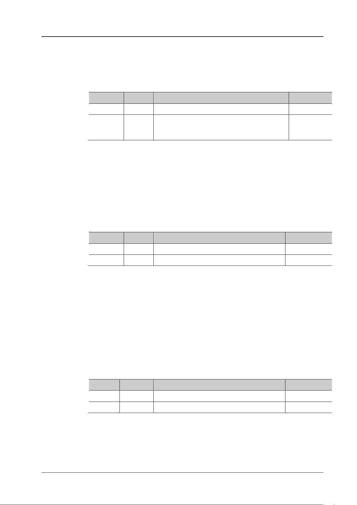
Chapter 2 Command System RIGOL
:BUS<n>:SPI:MOSI:SOURce?
Description
Sets or queries the MOSI data source of SPI decoding.
Name
Type
Range
Default
<n>
Discrete
{1|2|3|4}
——
el3|CHANnel4|OFF}
Format
D15, CHAN1, CHAN2, CHAN3, CHAN4, or OFF.
:BUS1:SPI:MOSI:SOURce? /*The query returns D0.*/
:BUS<n>:SPI:MOSI:POLarity?
Description
Sets or queries the polarity of MOSI data line of SPI decoding.
Name
Type
Range
Default
<n>
Discrete
{1|2|3|4}
——
<polarity>
Discrete
{HIGH|LOW}
LOW
Low: indicates that high level is 1, and low level is 0.
Format
:BUS1:SPI:MOSI:POLarity? /*The query returns HIGH.*/
:BUS<n>:SPI:DBITs?
Description
Sets or queries the data width of SPI decoding.
Name
Type
Range
Default
<n>
Discrete
{1|2|3|4}
——
<width>
Integer
4 to 32
8
Format
:BUS1:SPI:DBITs? /*The query returns 10.*/
:BUS<n>:SPI:MOSI:SOURce
Syntax :BUS<n>:SPI:MOSI:SOURc e <source>
Parameter
{D0|D1|D2|D3|D4|D5|D6|D7|D8|D9|D10|D11|
<source> Discrete
D12|D13|D14|D15|CHANnel1|CHANnel2|CHANn
OFF
Return
The query returns D0, D1, D2, D3, D4, D5, D6, D7, D8, D9, D10, D11, D12, D13, D14,
Example :BUS1:SPI:MOSI:SOURce D0 /*Sets the MOSI data source of SPI decoding to D0.*/
:BUS<n>:SPI:MOSI:POLarity
Syntax :BUS<n>:SPI:MOSI:POLarity <polarity>
Parameter
Remarks High: indicates that low level is 1, and high level is 0.
Return
Example
The query returns HIGH or LOW.
:BUS1:SPI:MOSI:POLarity HIGH /*Sets the polarity of MOSI data line to HIG H.*/
:BUS<n>:SPI:DBITs
Syntax :BUS<n>:SP I :DB ITs <wi dt h>
Parameter
Return
Example
MSO8000 Programming Guide 2-25
The query returns a n i nteger ranging from 4 to 32.
:BUS1:SPI:DBITs 10 /*Sets the data width of SPI decoding to 10.*/

RIGOL Chapter 2 Command System
:BUS<n>:SPI:ENDian?
Description
Sets or queries the endian of data transmission in SPI decoding.
Name
Type
Range
Default
<n>
Discrete
{1|2|3|4}
——
<endian>
Discrete
{MSB|LSB}
MSB
the data is transmitted first.
Format
:BUS1:SPI:ENDian? /*The query returns LSB.*/
:BUS<n>:SPI:MODE?
Description
Sets or queries the decode mode of SPI decoding.
Name
Type
Range
Default
<n>
Discrete
{1|2|3|4}
——
<mode>
Discrete
{CS|TIMeout}
TIMeout
command to set the timeout value.
Format
:BUS1:SPI:MODE? /*The query returns CS.*/
:BUS<n>:SPI:ENDian
Syntax :BUS<n>:SPI :EN Dia n <end i an>
Parameter
Remarks MSB: indicates Most Significant Bit transmission sequence, i.g. the highest bit of
the data is transmitted first.
LSB: indicates Least Significant Bit transmission sequence, i.g. the lowest bit of
Return
Example
The query returns MSB or LSB.
:BUS1:SPI:ENDian LSB /*Sets the endian of data transmission of SPI decoding
to LSB.*/
:BUS<n>:SPI:MODE
Syntax :BUS<n>:SPI :MODE <mode>
Parameter
Remarks CS: indicates chip select. CS: contains a chip select line ( C S). You can perform
frame synchronization according to CS.
TIMeout: indicates timed out. You can perform frame synchronization according to
the timeout. At this time, you can send the
:BUS<n>:SPI:TIMeout:TIME
Return
Example
The query returns CS or TIM.
:BUS1:SPI:MODE CS /*Sets the decode mode of SPI decoding to CS.*/
2-26 MSO8000 Programming Guide

Chapter 2 Command System RIGOL
:BUS<n>:SPI:TIMeout:TIME?
Description
Sets or queries the timeout value of SPI decoding. The default unit is s.
Name
Type
Range
Default
<n>
Discrete
{1|2|3|4}
——
<time>
Real
8 ns to 10 s
1 μs
This setting command is only valid in timeout mode.
Format
:BUS1:SPI:TIMeout:TIME? /*The query returns 5.000000E-6.*/
:BUS<n>:SPI:SS:SOURce?
Description
Sets or queries the source channel of the CS line of SP I decoding.
Name
Type
Range
Default
<n>
Discrete
{1|2|3|4}
——
nel3|CHANnel4}
Format
D15, CHAN1, CHAN2, CHAN3, or CHAN4.
:BUS1:SPI:SS:SOURce? /*The query returns D0.*/
:BUS<n>:SPI:TIMeout:TIME
Syntax :BUS<n>:SPI:TIMeout:TIME <time>
Parameter
Remarks The timeout must be greater than the maximum clock pulse width a nd less than
the idle time between frames.
Return
Example
The query returns the timeout value in scientific notation.
:BUS1:SPI:TIMeout:TIME 0.000005 /*Sets the timeout value to 5 μs.*/
:BUS<n>:SPI:SS:SOURce
Syntax :BUS<n>:SPI:SS:SOURce <source>
Parameter
{D0|D1|D2|D3|D4|D5|D6|D7|D8|D9|D10|D11|
<source> Real
Return
The query returns D0, D1, D2, D3, D4, D5, D6, D7 , D8, D9, D10, D11, D12, D13, D14,
Example :BUS1:SPI:SS:SOURce D0 /*Sets the source channel of CS line of SPI decoding to
D12|D13|D14|D15|CHANnel1|CHANnel2|CHAN
D0.*/
CHANnel1
MSO8000 Programming Guide 2-27

RIGOL Chapter 2 Command System
:BUS<n>:SPI:SS:POLarity?
Description
Sets or queries the polarity of the CS line of SPI decoding .
Name
Type
Range
Default
<n>
Discrete
{1|2|3|4}
——
<polarity>
Discrete
{HIGH|LOW}
LOW
line on the specified edge of the clock signal when the CS signal is low level.
Format
:BUS1:SPI:SS:POLarity? /*The query returns HIGH.*/
:BUS<n>:SPI:SS:POLarity
Syntax :BUS<n> :SPI:SS:POLarity <polar it y>
Parameter
Remarks HIGH: indicates that the oscilloscope samples data of the source channel of data
line on the specified edge of the clock signal when the CS signal is high level.
LOW: indicates that the oscilloscope samples da ta of the source channel of data
Return
Example
The query returns HIGH or LOW.
:BUS1:SPI:SS:POLarity HIGH /*Sets the polarity of CS line of SPI decoding to HIGH.*/
2-28 MSO8000 Programming Guide

Chapter 2 Command System RIGOL
:BUS<n>:CAN:SOURce?
Description
Sets or queries the source channel of CAN decoding.
Name
Type
Range
Default
<n>
Discrete
{1|2|3|4}
——
nel3|CHANnel4}
Format
D15, CHAN1, CHAN2, CHAN3, or CHAN4.
:BUS1:CAN:SOURce? /*The query returns D0.*/
:BUS<n>:CAN:STYPe?
Description
Sets or queries the signal type of CAN decoding.
Name
Type
Range
Default
<n>
Discrete
{1|2|3|4}
——
<stype>
Discrete
{TX|RX|CANH|CANL|DIFFerential}
RX
to the CAN_H bus signal and connect the negative lead to the CAN_L bus signal.
Format
:BUS1:CAN:STYPe? /*The query returns TX.*/
:BUS<n>:CAN (Option)
The :BUS<n>:CAN commands are used to set relevant parameters for CAN decoding.
Command List:
:BUS<n>:CAN:SOURce
:BUS<n>:CAN:STYPe
:BUS<n>:CAN:BAUD
:BUS<n>:CAN:SPOint
:BUS<n>:CAN:SOURce
Syntax :BUS<n>:CAN:SOURce <source>
Parameter
{D0|D1|D2|D3|D4|D5|D6|D7|D8|D9|D10|D11|
Return
<source> Discrete
The query returns D0, D1, D2, D3, D4, D5, D6, D7, D8, D9, D10, D11, D12, D13, D14,
D12|D13|D14|D15|CHANnel1|CHANnel2|CHAN
Example :BUS1:CAN:SOURce D0 /*Sets the source channel of CAN decoding to D0.*/
:BUS<n>:CAN:STYPe
Syntax :BUS<n>:CAN:STYPe <stype>
Parameter
Remarks TX: indicates the Transmit signal from the CAN bus transceiver.
RX: indicates the Receive signal from the CAN bus transceiver.
CANH: indicates the actual CAN_H bus signal.
CHANnel1
CANL: indicates the actual CAN_L bus signal.
DIFFerential: indicates the CA N differential bus signal connected to an analog
channel by using a differential probe. Connect the differential probe's positive lead
Return
Example
MSO8000 Programming Guide 2-29
The query returns TX, RX, CANH, CANL, or DIFF.
:BUS1:CAN:STYPe TX /*Sets the signal type of CAN decoding to TX.*/
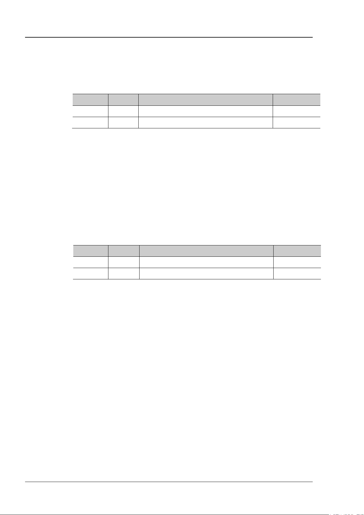
RIGOL Chapter 2 Command System
:BUS<n>:CAN:BAUD?
Description
Sets or queries the signal rate of CAN decoding. The default unit is bps.
Name
Type
Range
Default
<n>
Discrete
{1|2|3|4}
——
<baud>
Integer
10 kbps to 5 Mbps
1 Mbps
Format
:BUS1:CAN:BAUD? /*The query returns 120000.*/
:BUS<n>:CAN:SPOint?
Description
Sets or queries the sample point position of CAN decoding (expressed in %).
Name
Type
Range
Default
<n>
Discrete
{1|2|3|4}
——
<spoint>
Integer
10 to 90
50
the sample point" to "bit time", in %.
Format
:BUS1:CAN:SPOint? /*The query returns 70.*/
:BUS<n>:CAN:BAUD
Syntax :BUS<n>:CAN:BAUD <baud>
Parameter
Remarks If the baud rate is set to a value with "M", then "A" should be added at the end of the
value. For example, if you send 5 M, you need to send 5 MA.
Return
Example
The query returns an integer ranging from 10 kbps to 5 Mbps.
:BUS1:CAN:BAUD 120000 /*Sets the signal rate of CAN decod ing to 120000 bps.*/
:BUS<n>:CAN:SPOint
Syntax :BUS<n>:CAN:SPOint <sp oint>
Parameter
Remarks Sample point is a point within a bit’s time. The oscilloscope samples the bit level at this
point. The sample point position is expressed as the ratio of "time from the bit start to
Return
Example
The query returns an integer ranging from 10 to 90.
:BUS1:CAN:SPOint 70 /*Sets the sample point position of CAN decoding to 70%.*/
2-30 MSO8000 Programming Guide

Chapter 2 Command System RIGOL
:BUS<n>:FLEXray:BAUD?
Description
Sets or queries the signal rate of FlexRay decoding. The default unit is bps.
Name
Type
Range
Default
<n>
Discrete
{1|2|3|4}
——
<baud>
Discrete
{2500000|5000000|10000000}
10000000
Format
:BUS1:FLEXray:BAUD? /*The query returns 2500000.*/
:BUS<n>:FLEXray:SOURce?
Description
Sets or queries the source channel of FlexRay decoding.
Name
Type
Range
Default
<n>
Discrete
{1|2|3|4}
——
nel3|CHANnel4}
Format
D15, CHAN1, CHAN2, CHAN3, or CHAN4.
:BUS1:FlexRay:SOURce? /*The query returns D0.*/
:BUS<n>:FLEXray (Option)
The :BUS<n>:FLEXray commands are used to set the relevant parameters for FLEXray decoding.
Command List:
:BUS<n>:FLEXray:BAUD
:BUS<n>:FLEXray:SOURce
:BUS<n>:FLEXray:SPOint
:BUS<n>:FLEXray:STYPe
:BUS<n>:FLEXray:BAUD
Syntax :BUS<n>:FLEXray:BAUD <baud>
Parameter
Return
Example
The query returns 2500000, 5000000, or 10000000.
:BUS1:FLEXray:BAUD 2500000 /*Sets the signal rate of FlexRay decoding to
2500000 bps.*/
:BUS<n>:FLEXray:SOURce
Syntax :BUS<n>:FLEXray:SOURce <source>
Parameter
{D0|D1|D2|D3|D4|D5|D6|D7|D8|D9|D10|D11|
<source> Discrete
Return
The query returns D0, D1, D2, D3, D4, D5, D6, D7, D8, D9, D10, D11, D12, D13, D14,
Example :BUS1:FlexRay:SOURce D0 /*Sets the source channel of FlexRay decoding to D0.*/
D12|D13|D14|D15|CHANnel1|CHANnel2|CHAN
CHANnel1
MSO8000 Programming Guide 2-31

RIGOL Chapter 2 Command System
:BUS<n>:FLEXray:SPOint?
Description
Sets or queries the sample point position of FlexRay decoding (expressed in %).
Name
Type
Range
Default
<n>
Discrete
{1|2|3|4}
——
<spoint>
Integer
10 to 90
50
the sample point" to "bit time", in %.
Format
:BUS1:FLEXray:SPOint? /*The query returns 70.*/
:BUS<n>:FLEXray:STYPe?
Description
Sets or queries the signal type of FlexRay decoding.
Name
Type
Range
Default
<n>
Discrete
{1|2|3|4}
——
<stype>
Discrete
{BP|BM|RT}
BP
Format
:BUS1:FLEXray:STYPe? /*The query returns BM.*/
:BUS<n>:FLEXray:SPOint
Syntax :BUS<n>:FLEXray:SPOint <spoint>
Parameter
Remarks Sample point is a point within a bit’s time. The oscilloscope samples the bit level at this
point. The sample point position is expressed as the ratio of "time from the bit start to
Return
Example
The query returns an integer ranging from 10 to 90.
:BUS1:FLEXray:SPOint 70 /*Sets the sample point position of FlexRay decoding to
:BUS<n>:FLEXray:STYPe
Syntax :BUS<n>:FLEXray:STYPe <stype>
Parameter
Return
Example
The query returns BP, BM, or RT.
:BUS1:FLEXray:STYPe BM /*Sets the signal type of FlexRay decoding to BM.*/
70%.*/
2-32 MSO8000 Programming Guide
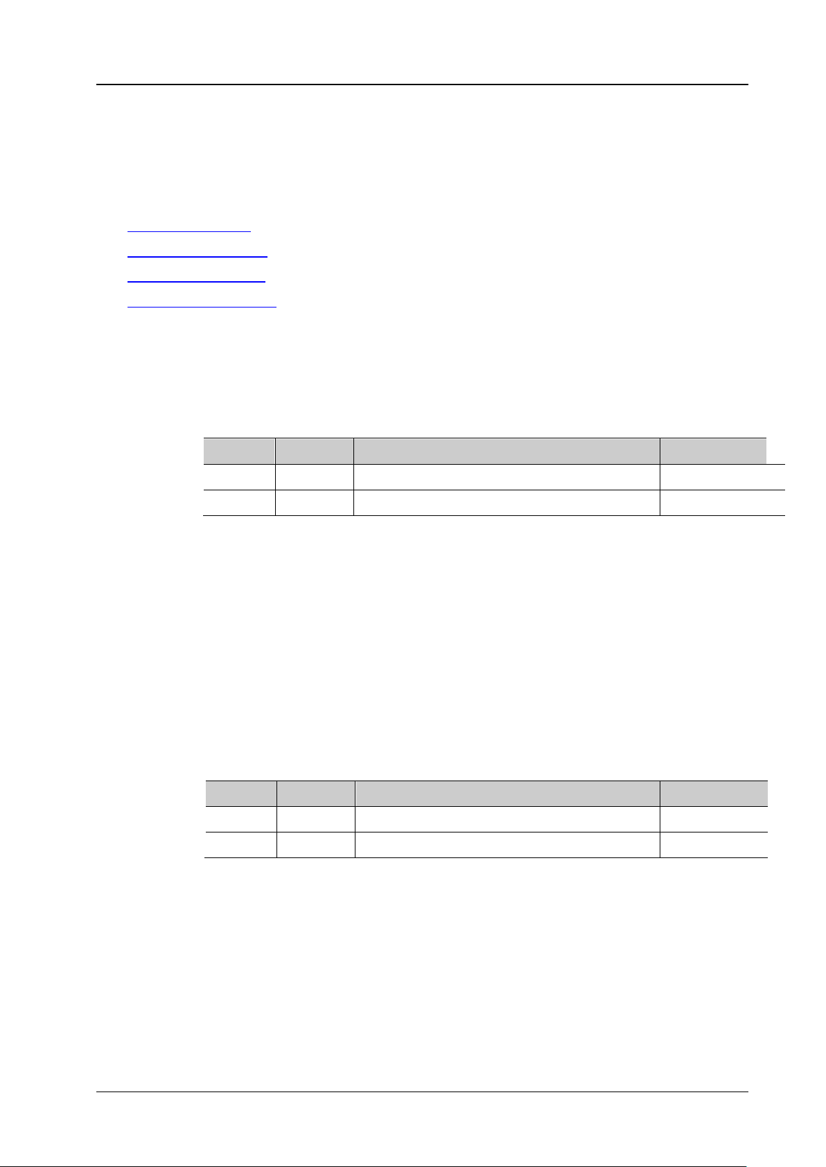
Chapter 2 Command System RIGOL
:BUS<n>:LIN:BAUD?
Name
Type
Range
Default
<n>
Discrete
{1|2|3|4}
——
<baud>
Integer
2.4 kbps to 20 Mbps
19200 bps
Format
:BUS1:LIN:BAUD? /*The query returns 9600.*/
:BUS<n>:LIN:POLarity?
Description
Sets or queries the parity bit of LIN decoding.
Name
Type
Range
Default
<n>
Discrete
{1|2|3|4}
——
<bool>
Bool
{{1|ON}|{0|OFF}}
0|OFF
Format
:BUS1:LIN:POLarity? /*The query return s 1.*/
:BUS<n>:LIN (Option)
The :BUS<n>:LIN commands are used to set relevant parameters for LIN decoding.
Command List:
:BUS<n>:LIN:BAUD
:BUS<n>:LIN:POLarity
:BUS<n>:LIN:SOURce
:BUS<n>:LIN:STANdard
:BUS<n>:LIN:BAUD
Syntax :BUS<n>:LIN:BAUD <baud>
Description
Sets or queries the baud rate of LIN decoding. The default unit is bps。
Parameter
Remarks If the baud rate is set to a value with "M", then "A" should be added at the end of the
value. For example, if you send 5 M, you need to send 5 MA.
Return
Example
The query returns a n i nteger ranging from 2.4 kbps to 20 Mbps.
:BUS1:LIN:BAUD 9600 /*Sets the baud rate of LIN decoding to 9600 bps.*/
:BUS<n>:LIN:POLarity
Syntax :BUS<n> :LI N :PO Lar ity <bool>
Parameter
Return
Example
The query returns 0 or 1.
:BUS1:LIN:POLarity ON /*Sets the parity bit to be included in LIN decoding.*/
MSO8000 Programming Guide 2-33

RIGOL Chapter 2 Command System
:BUS<n>:LIN:SOURce?
Description
Sets or queries the source of LIN bus.
Name
Type
Range
Default
<n>
Discrete
{1|2|3|4}
——
CHANnel1|CHANnel2|CHANnel3|CHANnel4}
Format
D15, CHAN1, CHAN2, CHAN3, or CHAN4.
:BUS1:LIN:SOURce? /*The query returns D0.*/
:BUS<n>:LIN:STANdard?
Description
Sets or queries the version of LIN bus.
Name
Type
Range
Default
<n>
Discrete
{1|2|3|4}
——
<value>
Discrete
V1X
Format
:BUS1:LIN:STANdard? /*The query returns V2X.*/
:BUS<n>:LIN:SOURce
Syntax :BUS<n>:LIN:SOURce <source>
Parameter
{D0|D1|D2|D3|D4|D5|D6|D7|D8|
<source> Discrete
D9|D10|D11|D12|D13|D14|D15|
CHANnel1
Return
The query returns D0, D1, D2, D3, D4, D5, D6, D7, D8, D9, D10, D11, D12, D13, D14,
Example :BUS1:LIN:S OURce D0 /*Sets the source of LIN bus to D0.*/
:BUS<n>:LIN:STANdard
Syntax :BUS<n>:LIN:STANdard <value>
Parameter
{V1X|V2X|MIXed}
Return
Example
The query returns V1X, V2X, or MIX.
:BUS1:LIN:STANdard V2X /*Sets the version of LIN bus to V2X.*/
2-34 MSO8000 Programming Guide

Chapter 2 Command System RIGOL
:BUS<n>:IIS:SOURce:CLOCk?
Description
Sets or queries the clock source of the I2S decoding.
Name
Type
Range
Default
<n>
Discrete
{1|2|3|4}
——
|CHANnel3|CHANnel4}
Format
D15, CHAN1, CHAN2, CHAN3, or CHAN4.
:BUS1:IIS:SOURce:CLOCk? /*The query returns D0.*/
:BUS<n>:IIS:SOURce:DATA?
Description
Sets or queries the data source of the I2S decoding.
Name
Type
Range
Default
<n>
Discrete
{1|2|3|4}
——
|CHANnel3|CHANnel4}
Format
D15, CHAN1, CHAN2, CHAN3, or CHAN4.
:BUS1:IIS:SOURce:DATA? /*The query returns D0.*/
:BUS<n>:IIS (Option)
The :BUS<n>:IIC commands are used to set relevant parameters for I2S decoding.
Command List:
:BUS<n>:IIS:SOURce:CLOCk
:BUS<n>:IIS:SOURce:DATA
:BUS<n>:IIS:SOURce:WSELect
:BUS<n>:IIS:ALIGnment
:BUS<n>:IIS:CLOCk:SLOPe
:BUS<n>:IIS:RWIDth
:BUS<n>:IIS:SOURce:CLOCk
Syntax :BUS<n>:IIS:SOURce:CLOCk <source>
Parameter
{D0|D1|D2|D3|D4|D5|D6|D7|D8|D9|D10|D
Return
<source> Discrete
11|D12|D13|D14|D15|CHANnel1|CHANnel2
The query returns D0, D1, D2, D3, D4, D5, D6, D7, D8, D9, D10, D11, D12, D13, D14,
CHANnel1
Example :BUS1:IIS:SOURce:CLOCk D0 /*Sets the clock source of the I2S decoding to D0.*/
:BUS<n>:IIS:SOURce:DATA
Syntax :BUS<n>:IIS:SOURce:DATA<source>
Parameter
{D0|D1|D2|D3|D4|D5|D6|D7|D8|D9|D10|D
<source> Discrete
11|D12|D13|D14|D15|CHANnel1|CHANnel2
CHANnel1
Return
The query returns D0, D1, D2, D3, D4, D5, D6, D7, D8, D9, D10, D11, D12, D13, D14,
Example :BUS1:IIS:SOURce:DATA D0 /*Sets the data source of the I2S decoding to D0.*/
MSO8000 Programming Guide 2-35

RIGOL Chapter 2 Command System
:BUS<n>:IIS:SOURce:WSELect?
Description
Sets or queries the audio channel of the I2S trigger.
Name
Type
Range
Default
<n>
Discrete
{1|2|3|4}
——
HANnel3|CHANnel4}
Format
D15, CHAN1, CHAN2, CHAN3, or CHAN4.
:BUS1:IIS:SOURce:WSELect? /*The query returns CHAN2.*/
:BUS<n>:IIS:ALIGnment?
Description
Sets or queries the alignment mode of the I2S decoding.
Name
Type
Range
Default
<n>
Discrete
{1|2|3|4}
——
<align>
Discrete
IIS
LJ: data transmission (MSB first) begins at the edge of the WS transition.
Format
:BUS1:IIS:ALIGnment? /*The query retur ns RJ.*/
:BUS<n>:IIS:CLOCk:SLOPe?
Description
Sets or queries the clock edge type of I2S decoding.
Name
Type
Range
Default
<n>
Discrete
{1|2|3|4}
——
<slope>
Discrete
{NEGative|POSitive}
POSitive
Format
:BUS1:IIS:CLOCk:SLOPe? /*The query returns NEG.*/
:BUS<n>:IIS:SOURce:WSELect
Syntax :BUS<n>:IIS:SOURce:WSE Lect <source>
Parameter
{D0|D1|D2|D3|D4|D5|D6|D7|D8|D9|D10|D1
<source> Discrete
1|D12|D13|D14|D15|CHANnel1|CHANnel2|C
CHANnel1
Return
The query returns D0, D1, D2, D3, D4, D5, D6, D7, D8, D9, D10, D11, D12, D13, D14,
Example :BUS1:IIS:SOURce:WSELect CHANnel2 /*Sets the audio channel to CHANnel2.*/
:BUS<n>:IIS:ALIGnment
Syntax :BUS<n>:IIS:ALIGnment <align>
Parameter
{IIS|RJ|LJ}
Remarks IIS: first sends MSB of each sample data and then s ends LSB.
RJ: data t ransmission (MSB first) is right-justified to the WS transition.
Return
Example
The query returns I IS, RJ, or LJ.
:BUS1:IIS:ALIGnment RJ /*Sets the alignment mode of the I2S decoding to RJ.*/
:BUS<n>:IIS:CLOCk:SLOPe
Syntax :BUS<n>:IIS:CLOCk:SLOPe <slope>
Parameter
Return
Example
2-36 MSO8000 Programming Guide
The query returns POS or NEG.
:BUS1:IIS:CLOCk:SLOPe NEGative /*Sets the clock edge of I2S decoding to
NEGative.*/

Chapter 2 Command System RIGOL
:BUS<n>:IIS:RWIDth?
Description
Sets or queries the word size of the I2S decoding.
Name
Type
Range
Default
<n>
Discrete
{1|2|3|4}
——
<val>
Integer
4 to 32
8
Format
:BUS1:IIS:RWIDth? /*The query returns 5.*/
:BUS<n>:IIS:RWIDth
Syntax :BUS<n>:IIS:RWIDth <val>
Parameter
Return
Example
The query returns a n i nteger ranging from 4 to 32.
:BUS1:IIS:RWIDth 5 /*Sets the word size of I2S decoding to 5.*/
MSO8000 Programming Guide 2-37

RIGOL Chapter 2 Command System
:BUS<n>:M1553:SOURce?
Description
Sets or queries the source of the M1553 decoding.
Name
Type
Range
Default
<n>
Discrete
{1|2|3|4}
——
<source>
Discrete
{CHANnel1|CHANnel2|CHANnel3|CHANnel4}
CHANnel1
Format
/*The query returns CHAN2.*/
:BUS<n>:M1553 (Option)
The :BUS<n>:M1553 commands are used to set relevant parameters for the M1553 decoding.
Command List:
:BUS<n>:M1553:SOURce
:BUS<n>:M1553:SOURce
Syntax :BUS<n> :M 15 53 :SO UR ce <s o urce >
Parameter
Return
Example
The query returns CHAN1, CHAN2, CHAN3, or CHAN4.
:BUS1:M1553:SOURce CHANnel2
/*Sets the source of the M1553 decoding to CHANnel2.*/
:BUS1:M1553:SOURce?
2-38 MSO8000 Programming Guide

Chapter 2 Command System RIGOL
:CHANnel<n>:BWLimit?
Description
Sets or queries the bandwidth limit of the specified channel.
Name
Type
Range
Default
<n>
Discrete
{1|2|3|4}
1
<type>
Discrete
Refer to Remarks
OFF
signal under test can pass through the channel.
Format
:CHANnel1:BWLimit? /*The query returns 20M.*/
:CHANnel<n> Commands
The :CHANnel<n> commands are used to set or query the bandwidth limit, coupling, vertical scale, vertical
offset, and other vertical system parameters of the analog channel.
Command List:
:CHANnel<n>:BWLimit
:CHANnel<n>:COUPling
:CHANnel<n>:DISPlay
:CHANnel<n>:INVert
:CHANnel<n>:OFFSet
:CHANnel<n>:TCALibrate
:CHANnel<n>:SCALe
:CHANnel<n>:IMPedance
:CHANnel<n>:CSTart
:CHANnel<n>:PROBe
:CHANnel<n>:PROBe:DELay
:CHANnel<n>:PROBe:BIAS
:CHANnel<n>:UNITs
:CHANnel<n>:VERNier
:CHANnel<n>:BWLimit
Syntax :CHANnel<n>:BWLimit <type>
Parameter
Remarks The range of <type> is related to the instrument model.
MSO8064: {20M|OFF}
MSO8104: {20M|250M|OFF}
20M, 250M: When you enable the bandwidth limit and limit it to 20 MHz or 250 MHz,
the high frequency c omponents found in the signal under tes t that are greater t han
20 MHz or 250 MHz are attenuated.
OFF: disables the bandwidth limit function. The high-frequency components in the
Return
Example
MSO8000 Programming Guide 2-39
The query returns 20M, 250M, or OFF.
:CHANnel1:BWLimit 20M /*Enables the 20 MHz bandwidth limit.*/

RIGOL Chapter 2 Command System
:CHANnel<n>:COUPling?
Description
Sets or queries the coupling mode of the specified channel.
Name
Type
Range
Default
<n>
Discrete
{1|2|3|4}
1
<coupling>
Discrete
{AC|DC|GND}
DC
GND: the DC and AC components of the signal u nder test are both blocked.
Format
:CHANnel1:COUPling? /*The query returns AC.*/
:CHANnel<n>:DISPlay?
channel.
Name
Type
Range
Default
<n>
Discrete
{1|2|3|4}
1
<bool>
Bool
{{1|ON}|{0|OFF}}
0|OFF
Format
:CHANnel1:DISPlay? /*The query returns 1.*/
:CHANnel<n>:INVert?
status of the waveform invert for the specified channel.
Name
Type
Range
Default
<n>
Discrete
{1|2|3|4}
1
<bool>
Bool
{{1|ON}|{0|OFF}}
0|OFF
When the waveform invert is turned off, the waveform is displayed normally; when
inverted.
:CHANnel<n>:COUPling
Syntax :CHANnel<n>:COUPling <coupling>
Parameter
Remarks AC: the DC components of the signal under test are blocked.
DC: both DC and AC components of the signal under test can pass through the
channel.
Return
Example
The query returns AC, DC, or GND.
:CHANnel1:COUPling AC /*Selects the AC coupling mode.*/
:CHANnel<n>:DISPlay
Syntax :CHANnel<n>:DISPlay <bool>
Description Turns on or off the specified channel; or queries the on/off status of the specified
Parameter
Return
Example
The query returns 1 or 0.
:CHANnel1:DISPlay ON /*Enables CH1.*/
:CHANnel<n>:INVert
Syntax :CHANnel<n>:INVert <bool>
Description Turns on or off the waveform invert for the specified channel; or queries the on/off
Parameter
Remarks
the waveform inv ert is turned on, the v oltage v alues of the d isplay ed wav efo rm are
2-40 MSO8000 Programming Guide

Chapter 2 Command System RIGOL
Return Format
The query returns 1 or 0.
:CHANnel1:INVert? /*The query returns 1.*/
:CHANnel<n>:OFFSet?
Description
Sets or queries the vertical offset of the specified channel. The default unit is V.
Name
Type
Range
Default
<n>
Discrete
{1|2|3|4}
1
Related to vertical scale and input
Format
:CHANnel1:OFFSet? /*The query returns 1E-2.*/
:CHANnel<n>:TCALibrate?
corresponding channel) of the specified channel. The default unit is s.
Name
Type
Range
Default
<n>
Discrete
{1|2|3|4}
1
automatically. In different horizontal time bases, the step values for the parameter are
set.
Format
:CHANnel1:TCALibrate? /*The query returns 2.000000E-8.*/
Example :CHANnel1:INVert ON /*Enables the waveform invert for CH1.*/
:CHANnel<n>:OFFSet
Syntax :CHANnel<n>:OFFSet <offset>
Parameter
impedance
when the input impedance is 1 MΩ:
±1 V (1 mV/div to 50 mV/div).
±30 V (51 mV/di v to 260 mV/div)
<offset> Real
±100 V (265 mV/div to 10 V/div)
0 V
When the input impedance is 50 Ω:
±1 V (1 mV/div to 100 mV/div)
±4 V (102 mV/div to 1 V/div)
Return
Example
The query returns the vertical offset in scientific notation.
:CHANnel1:OFFSet 0.01 /*Sets the vertical offset of CH1 to 10 mV.*/
:CHANnel<n>:TCALibrate
Syntax :CHANnel<n>:TCALibrate <val>
Description Sets or queries the delay calibration time (used to calibrate the zero offset of the
Parameter
<val> Real -100 ns to 100 ns 0 s
Remarks Set the parameter <val> to a specific value at a specified step. If the parameter value
is not within the settable range, select the value that is closest to the range
different.
When the horizontal time base is greater than 10 μs, the parameter <val> cannot be
Return
Example
MSO8000 Programming Guide 2-41
The query returns the delay calibration time in scientific notation.
:CHANnel1:TCALibrate 0.00000002 /*Set s the delay calibration time to 20 ns.*/
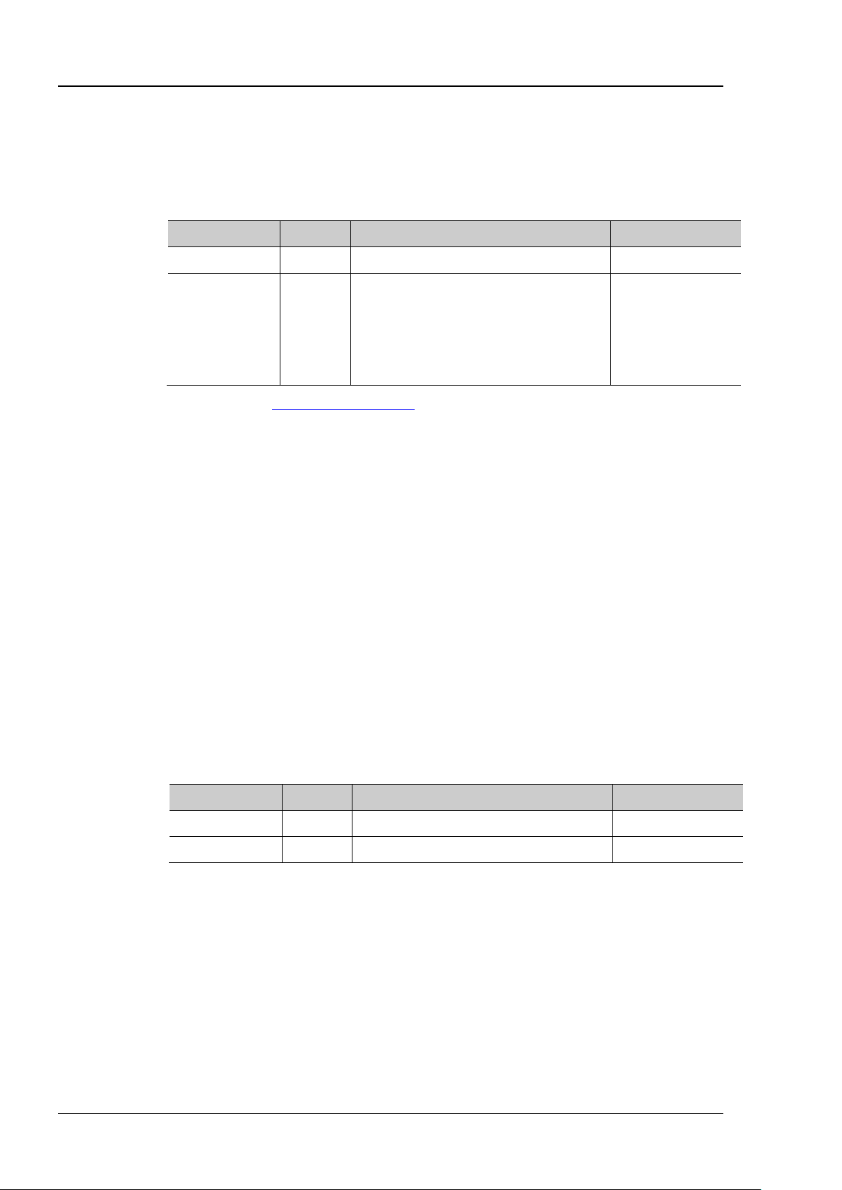
RIGOL Chapter 2 Command System
:CHANnel<n>:SCALe?
Description
Sets or queries the vertical scale of the specified channel. The default unit is V.
Name
Type
Range
Default
<n>
Discrete
{1|2|3|4}
1
probe ratio is 1X: 1 mV to 1 V
details.
Format
:CHANnel1:SCALe? /*The query returns 1.*/
:CHANnel<n>:IMPedance?
Ω.
Name
Type
Range
Default
<n>
Discrete
{1|2|3|4}
1
<impedance>
Discrete
{OMEG|FIFTy}
OMEG
whose output impedance is 50 Ω.
Format
:CHANnel1:IMPedance? /*The query returns FIFT.*/
:CHANnel<n>:SCALe
Syntax :CHANnel<n>:SCALe <scale>
Parameter
Related to input impedance and probe
ratio:
<scale> Real
Remarks You can use the :CHANnel<n>:VERNier command to enable or disable the fine
adjustment setting for the vertical scale of the specified channel. By default, the fine
adjustment is Off. At this time, you can set the vertical scale at 1-2-5 step, i.g. 10 mV, 20
mV, 50 mV,…100 V. When the fine adjustment is enabled, you can further adjust the
vertical scale within a relatively smaller range to improve vertical resolution. If the
amplitude of the input waveform is a little bit greater than the full scale under the current
scale and the amplitude would be a little bit lower if the next scale is used, fine
adjustment can be used to improve the amplitude of waveform display to view signal
when the input impedance is 1 MΩ, the
probe ratio is 1X: 1 mV to 10 V
when the input impedance is 50 Ω, the
100 mV
Return
Example
The query returns the vertical scale in scientific notation.
:CHANnel1:SCALe 1 /*Sets t he vertical scale of CH1 to 1 V.*/
:CHANnel<n>:IMPedance
Syntax :CHANnel<n>:IMPedance <impedance>
Description Sets or queries the input impedance of the specified analog channel. The default unit is
Parameter
Remarks OMEG: 1 MΩ. This indicates that the input impedance of the oscilloscope is rather
high, and the current flowing from the circuit under test to the oscilloscope can be
ignored.
FIFTy: 50 Ω. This indicates that the oscilloscope shall be matched with a device
Return
Example
The query returns OMEG or FIFT.
:CHANnel1:IMPedance FIFTy /*Sets the input impedance of CH1 to FIFTy.*/
2-42 MSO8000 Programming Guide

Chapter 2 Command System RIGOL
Syntax
:CHANnel<n>:CSTart
Description
Starts calibration for the active probe currently connected to the specified analog channel.
Name
Type
Range
Default
<n>
Discrete
{1|2|3|4}
1
Remarks
This command is only valid when an ac tive probe is correctly connecte d.
:CHANnel<n>:PROBe?
Description
Sets or queries the probe ratio of the specified channe l.
Name
Type
Range
Default
<n>
Discrete
{1|2|3|4}
1
50000}
The set probe ratio affects the settable range of the current vertical scale.
Format
2000, 5000, 10000, 20000, or 50000.
:CHANnel1:PROBe? /*The query returns 10.*/
:CHANnel<n>:PROBe:DELay?
Description
Sets or queries the probe delay time of the specified channel.
Name
Type
Range
Default
<n>
Discrete
{1|2|3|4}
1
<delay>
Real
-100 ns to 100 ns
0 s
This command is only valid when an active probe is correctly connected.
Format
:CHANnel<n>:CSTart
Parameter
:CHANnel<n>:PROBe
Syntax :CHANnel<n>:PROBe <atten>
Parameter
{0.01|0.02|0.05|0.1|0.2|0.5|1|2|5|10|20|50|
<atten> Discrete
100|200|500|1000|2000|5000|10000|20000|
1
Remarks Sets the probe ratio. That is, multiply the acquired signal by a specified number (not
affect the actual amplitude of the signal).
Return
The query returns 0.01, 0.02, 0.05, 0.1, 0.2, 0.5, 1, 2, 5, 10, 20, 50, 100, 200, 500, 1000,
Example :CHANnel1:PROBe 10 /*Sets the probe ratio of CH1 to 10X.*/
:CHANnel<n>:PROBe:DELay
Syntax :CHANnel<n>:PROBe:DELay <delay>
Parameter
Remarks To avoid measurement result errors arising from the transmission delay of the probe
cable, the oscilloscope provides the probe delay adjustment function for the active
probe.
Return
The query returns the probe delay ti me in scientific notation.
MSO8000 Programming Guide 2-43

RIGOL Chapter 2 Command System
:CHANnel<n>:PROBe:BIAS?
Description
Sets or queries the probe bias voltage of the specified channel.
Name
Type
Range
Default
<n>
Discrete
{1|2|3|4}
1
<bias>
Real
-5 V to 5 V
0 V
This command is only valid when an active probe is correctly connected.
Format
:CHANnel<n>:UNITs?
Description
Sets or queries the amplitude display unit of the specified analog channel.
Name
Type
Range
Default
<n>
Discrete
{1|2|3|4}
1
<units>
Discrete
{VOLTage|WATT|AMPere|UNKNown}
VOLTage
Format
:CHANnel1:UNITs? /*The query returns VOLT.*/
:CHANnel<n>:VERNier?
of the specified anal og channel.
Name
Type
Range
Default
<n>
Discrete
{1|2|3|4}
1
<bool>
Bool
{{1|ON}|{0|OFF}}
0|OFF
step, i.g. 10 mV, 20 mV, 50 mV, 100 mV …100 V. When the fine adjustment is enabled, you
used, fine adjustment can be used to improve th e amplitude of wav ef orm dis play to view
:CHANnel<n>:PROBe:BIAS
Syntax :CHANnel<n>:PROBe:BIAS <bias>
Parameter
Remarks This function is used to adjust the signal under test that exceeds the input dynamic
range of the probe amplifier to an appropriate range to ensure the signal integrity.
Return
The query returns the probe bias voltage in scientific n otation.
:CHANnel<n>:UNITs
Syntax :CHANnel< n >: UNITs <units>
Parameter
Return
Example
The query returns VOLT, WATT, AMP, or UNKN.
:CHANnel1:UNITs VOLTage /*Sets the amplitude display unit of CH1 to VOLTage.*/
:CHANnel<n>:VERNier
Syntax :CHANnel<n>:VERNier <bool>
Description Enables or disables the fine adjustment of the vertical scale of the specified analog
channel; or queries the on/off status of the fine adjustment function of the vertical scale
Parameter
Remarks By default, the fine adjustment is Off. At this time, you can set the vertical scale at 1-2-5
can further adjust the vertical scale within a relatively smaller range to improve vertical
resolution. If the amplitude of the input waveform is a little bit greater than the full scale
under the current scale and the amplitude would be a little bit lower if the next scale is
2-44 MSO8000 Programming Guide

Chapter 2 Command System RIGOL
signal details.
Format
:CHANnel1:VERNier? /*The query returns 1.*/
Return
Example
The query returns 1 or 0.
:CHANnel1:VERNier ON /*Enables the fine adjustment of the vertical scale of CH1.*/
MSO8000 Programming Guide 2-45
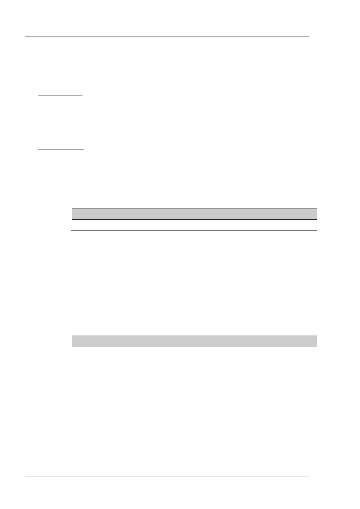
RIGOL Chapter 2 Command System
:CLOCk:METHod?
Description
Sets or queries the clock recovery method.
Name
Type
Range
Default
<type>
Discrete
{CONStant|PLL|EXPLicit}
CONStant
Remarks
The clock recover y provides an ideal clock for comparison to actual signal edges.
Format
:CLOCk:METHod? /*The query returns PLL.*/
:CLOCk:TYPE?
Description
Sets or queries the data rate type of the constant clock recovery method.
Name
Type
Range
Default
<type>
Discrete
{AUT|SEM|MAN}
AUT
Format
/*The query returns AUT.*/
:CLOCk Commands
Command List:
:CLOCk:METHod
:CLOCk:TYPE
:CLOCk:RATE
:CLOCk:PLL:ORDer
:CLOCk:PLL:BW
:CLOCk:EXTChan
:CLOCk:METHod
Syntax :CLOCk:METHod <type>
Parameter
Return
Example
The query returns CONS, PLL, or EXPL.
:CLOCk:METHod PLL /*Sets the clock recovery method to PLL.*/
:CLOCk:TYPE
Syntax :CLOCk:TYPE <type>
Parameter
Return
Example
The query returns AUT, SEM, or MAN.
:CLOCk:TYPE AUT
/*Sets the data rate type of the constant clock recovery method to AUT.*/
:CLOCk:TYPE?
2-46 MSO8000 Programming Guide

Chapter 2 Command System RIGOL
:CLOCk:RATE?
Description
Sets or queries the data rate of the Manual method.
Name
Type
Range
Default
Format
:CLOCk:RATE? /*The query returns 10000000.*/
:CLOCk:PLL:ORDer?
Description
Sets or queries the PLL order.
Name
Type
Range
Default
<ord>
Discrete
{ONE|TWO}
ONE
Format
:CLOCk:PLL:ORDer? /*The query returns TWO.*/
:CLOCk:PLL:BW?
Description
Sets or queries the PLL loop bandwidth.
Name
Type
Range
Default
Format
:CLOCk:PLL:BW? /*The query returns 100000.*/
:CLOCk:RATE
Syntax :CLOCk:RATE <val>
Parameter
<val> Integer 1 Mb/s to 4 Gb/s 500 Mb/s
Return
Example
The query returns the data rate of the Manual method in integer.
:CLOCk:RATE 10000000 /*Sets the data rate of the Manual method to 10 Mb/s.*/
:CLOCk:PLL:ORDer
Syntax :CLOCk:PLL:ORDer <ord>
Parameter
Return
Example
The query returns ONE or TWO.
:CLOCk:PLL:ORDer TWO /*Sets the PLL order to TWO.*/
:CLOCk:PLL:BW
Syntax :CLOCk:PLL :B W <val>
Parameter
Return
Example
<val> Integer 1 kHz to 1 MHz 300 kHz
The query returns the PLL loop bandwidth in integer.
:CLOCk:PLL:BW 100000 /*Sets the PLL loop bandwidth to 100 kHz.*/
MSO8000 Programming Guide 2-47

RIGOL Chapter 2 Command System
:CLOCk:EXTChan?
Description
Sets or queries the source of the external clock recovery method.
Name
Type
Range
Default
<ch>
Discrete
{CHANnel1|CHANnel2|CHANnel3|CHANnel4}
CHANnel2
Format
/*The query returns CHAN3.*/
:CLOCk:EXTChan
Syntax :CLOCk:EXTChan <c h>
Parameter
Return
Example
The query returns CHAN1, CHAN2, CHAN3, or CHAN4.
:CLOCk:EXTChan CHANnel3
/*Sets the source of the external clock recovery method to CH3.*/
:CLOCk:EXTChan?
2-48 MSO8000 Programming Guide

Chapter 2 Command System RIGOL
Syntax
:COUNter:CURRent?
Description
Queries the measurement value of the frequency counter.
Format
:COUNter:ENABle?
the frequency counter.
Name
Type
Range
Default
<bool>
Bool
{{1|ON}|{0|OFF}}
0|OFF
Format
:COUNter:ENABle? /*The query returns 1.*/
:COUNter:SOURce?
Description
Sets or queries the source of the frequency counter.
Name
Type
Range
Default
ANnel3|CHANnel4|EXT}
Format
D13, D14, D15, CHAN1, CHAN2, CHAN3, CHAN4, or EXT.
:COUNter Commands
Command List:
:COUNter:CURRent?
:COUNter:ENABle
:COUNter:SOURce
:COUNter:MODE
:COUNter:NDIGits
:COUNter:TOTalize:ENABle
:COUNter:TOTalize:CLEar
:COUNter:CURRent?
Return
The query returns 1.000006E+3.
:COUNter:ENABle
Syntax :COUNter:ENABle <bool >
Description Enables or disables the frequency counter; or queries the on/off status of
Parameter
Return
Example
The query returns 1 or 0.
:COUNter:ENABle ON /*Enables the frequency counter.*/
:COUNter:SOURce
Syntax :COUNter:SOURce <sour ce >
Parameter
<source> Discrete
Return
MSO8000 Programming Guide 2-49
The query returns D0, D1, D2, D3, D4, D5, D6, D7, D8, D9, D10, D11, D12,
{D0|D1|D2|D3|D4|D5|D6|D7|
D8|D9|D10|D11|D12|D13|D14
|D15|CHANnel1|CHANnel2|CH
CHANnel1

RIGOL Chapter 2 Command System
:COUNter:SOURce? /*The query returns CHAN2.*/
:COUNter:MODE?
Description
Sets or queries the mode of the frequency counter.
Name
Type
Range
Default
<mode>
Discrete
{FREQuency|PERiod|TOTalize}
FREQuency
Format
:COUNter:MODE PERiod /*Sets the mode of the frequency counter to
:COUNter:MODE? /*The query returns PER.*/
:COUNter:NDIGits?
Description
Sets or queries the resolution of the frequency counter.
Name
Type
Range
Default
<val>
Integer
3-6
5
unavailable for "Totalize".
Format
:COUNter:NDIGits? /*The query returns 4.*/
:COUNter:TOTalize:ENABle?
queries the on/off status of the statistical function of the frequency counter.
Name
Type
Range
Default
<bool>
Bool
{{1|ON}|{0|OFF}}
0|OFF
Remarks
Not available for "Period" and "Frequency".
Format
Example :COUNter:SOURce CHANnel2 /*Sets the source of the frequency
counter to CHANnel2.*/
:COUNter:MODE
Syntax :COUNter:MODE <mode>
Parameter
Return
Example
The query returns FREQ, PER, or TOT.
PERiod.*/
:COUNter:NDIGits
Syntax :COUNter : NDI Gi ts <val>
Parameter
Remarks The resolution setting is only available for "Period" and "Frequency", and
Return
Example
The query returns an integer ranging from 3 to 6.
:COUNter:NDIGits 4 /*Sets the resolution of the frequency
counter to 4.*/
:COUNter:TOTalize:ENABle
Syntax :COUNter:TOTalize:ENABle <bool >
Description Enables or disables the statistica l function of the frequency counter; or
Parameter
Return
2-50 MSO8000 Programming Guide
The query returns 1 or 0.

Chapter 2 Command System RIGOL
:COUNter:TOTalize:ENABle? /*The query returns 1.*/
Syntax
:COUNter:TOTalize:CLEar
Description
Clears the total count.
Description
Available when "Totalize" is selected under "Measure".
Example :COUNter:TOTalize:ENABle ON /*Enables the statistical function of the
frequency counter.*/
:COUNter:TOTalize:CLEar
MSO8000 Programming Guide 2-51

RIGOL Chapter 2 Command System
:CURSor Commands
The :CURSor commands are used to measure th e X axis v alues (e.g. Time) and Y axis v alues (e. g. V oltage)
of the waveform on the screen.
Command List:
:CURSor:MODE
:CURSor:MANual
:CURSor:TRACk
:CURSor:XY
2-52 MSO8000 Programming Guide

Chapter 2 Command System RIGOL
:CURSor:MODE?
Description
Sets or queries the mode of the cursor measurement.
Name
Type
Range
Default
<mode>
Discrete
{OFF|MANual|TRACk|XY|MEASure}
OFF
MEASure: enables the measure cursor mode.
Format
:CURSor:MODE? /*The quer y returns MAN.* /
:CURSor:MODE
Syntax :CURSor:MODE <mode>
Parameter
Remarks OFF: disables the cursor measurement function.
MANual: enables the manual mode of cursor measurement.
TRACk: enables the track cursor mode.
XY: enables the XY cursor measurement mode. This mode is valid when you select
"XY" for the horizontal time base.
Return
Example
The query returns OFF, MAN, TRAC, XY, or MEAS.
:CURSor:MODE MANual /*Selects the manual cursor measurement mode.*/
MSO8000 Programming Guide 2-53

RIGOL Chapter 2 Command System
:CURSor:MANual:TYPE?
Description
Sets or queries the cursor type in the manual mode of cursor measurement.
Name
Type
Range
Default
<type>
Discrete
{TIME|AMPLitude}
TIME
parameters.
Format
:CURSor:MANual:TYPE? /*The query returns AMPL.*/
:CURSor:MANual
Command List:
:CURSor:MANual:TYPE
:CURSor:MANual:SOURce
:CURSor:MANual:TUNit
:CURSor:MANual:VUNit
:CURSor:MANual:CAX
:CURSor:MANual:CBX
:CURSor:MANual:CAY
:CURSor:MANual:CBY
:CURSor:MANual:AXValue?
:CURSor:MANual:AYValue?
:CURSor:MANual:BXValue?
:CURSor:TRACk:BYValue?
:CURSor:MANual:XDELta?
:CURSor:MANual:IXDELta?
:CURSor:MANual:YDELta?
:CURSor:MANual:TYPE
Syntax :CURSor:MANual:TYPE <type>
Parameter
Remarks TIME: indicates X cursor, which is often used to measure the time parameters.
AMPLitude: indi cates Y cursor, which is often used to measure the voltage
Return
Example
The query returns TIME or AMPL.
:CURSor:MANual:TYPE AMPLitude /*Sets the cursor type to AMPLitude.*/
2-54 MSO8000 Programming Guide

Chapter 2 Command System RIGOL
:CURSor:MANual:SOURce?
Description
Sets or queries the channel source of the manual mode of cursor measurement.
Name
Type
Range
Default
MATH1|MATH2|MATH3|MATH4|LA|NONE}
When LA is selected, the cursor type cannot be set to Y (:CURSor:MANual:TYPE).
Format
LA, or NONE.
:CURSor:MANual:SOURce? /*The query returns CHAN2.*/
:CURSor:MANual:TUNit?
Description
Sets or queries the horizontal unit in the manual mode of cursor measurement.
Name
Type
Range
Default
<unit>
Discrete
{SECond|HZ|DEGRee|PERCent}
SECond
percentage.
Format
:CURSor:MANual:TUNit? /*The query returns DEGR.*/
:CURSor:MANual:SOURce
Syntax :CURSor:M A Nua l :SO UR ce <so urce>
Parameter
<source> Discrete
{CHANnel1|CHANnel2|CHANnel3|CHANnel4|
Remarks Only the currently enabled channel can be selected as the channel source.
Return
The query returns CHAN1, CHAN2, CHAN3, CHAN4, MATH1, MATH2, MATH3, MATH4,
Example :CURSor:MAN ual:SOURce CHANnel2 /*Sets the channel source to CHANnel2.*/
:CURSor:MANual:TUNit
Syntax :CURSor:MANual:TUNit <unit>
Parameter
Remarks
SECon d: in th e mea surem ent results, AX, BX, and △X are expresse d in "s"; 1/△X in
"Hz".
HZ: in the m easurem ent results, AX, BX, and △X are expressed in "Hz"; 1/△X in
"s".
CHANnel1
DEGRee: in the m easurement results, AX, BX, and △X are expressed in "°".
PERCent: in the m easurem ent results, AX, BX, and △X are expressed in
Return
Example
The query returns SEC, HZ, DEGR, or PERC.
:CURSor:MANual:TUNit DEGRee /*Sets the hor izontal unit to DEGRee.*/
MSO8000 Programming Guide 2-55

RIGOL Chapter 2 Command System
:CURSor:MANual:VUNit?
Description
Sets or queries the vertical unit in the manual mode of cursor measurement.
Name
Type
Range
Default
{SOURce|PERCent}
percentage.
Format
:CURSor:MANual:VUNit? /*The query returns PERC.*/
:CURSor:MANual:CAX?
measurement.
Name
Type
Range
Default
<ax>
Integer
0 to 999
400
999, and the pixel range in the vertical direction is from 0 to 479.
Format
:CURSor:MANual:CAX? /*The query returns 200.*/
:CURSor:MANual:VUNit
Syntax :CURSor:MANual:VUNi t <unit>
Parameter
<unit> Discrete
SOUR
Remarks SOURce: in the measurement results, the unit of AY, BY, and △Y are automatically
set to the unit of the current source.
PERCent: in the measurement results, the unit of AY, BY, and △Y are expressed in
Return
Example
The query returns SOUR or PERC.
:CURSor:MANual:VUNit PERCent /*Sets AY, BY, and △Y to be expressed in percentage in
the measurement results.*/
:CURSor:MANual:CAX
Syntax :CURSor :MANual:CAX <ax >
Description Sets or queries the horizontal position of Cursor A in the manual mode of cursor
Parameter
Remarks The horizontal and vertical position of the cursor is defined by the screen pixel coordinate.
The range of the screen pixel coordinate is from (0,0) to (999,479). Wherein, (0,0) is a
location at the upper-left corner of the screen, and (999,479) is a location at the
lower-right corner of the screen. The pixel range in the horizontal direction is from 0 to
Return
Example
The query returns a n i nteger ranging from 0 to 999.
:CURSor:MANual:CAX 200 /*Sets the horizontal position of Cursor A to 200.*/
2-56 MSO8000 Programming Guide

Chapter 2 Command System RIGOL
:CURSor:MANual:CBX?
measurement.
Name
Type
Range
Default
<bx>
Integer
0 to 999
600
999, and the pixel range in the vertical direction is from 0 to 479.
Format
:CURSor:MANual:CBX? /*The query returns 200.*/
:CURSor:MANual:CAY?
measurement.
Name
Type
Range
Default
<ay>
Integer
0 to 479
180
measurement, this command is invalid.
Format
:CURSor:MANual:CBX
Syntax :CURSor :MANual:CBX <bx >
Description Sets or queries the horizonta l position of Cursor B in the manual mode of cursor
Parameter
Remarks The horizontal and vertical position of the cursor is defined by the screen pixel coordinate.
The range of the screen pixel coordinate is from (0,0) to (999,479). Wherein, (0,0) is a
location at the upper-left corner of the screen, and (999,479) is a location at the
lower-right corner of the screen. The pixel range in the horizontal direction is from 0 to
Return
Example
The query returns a n i nteger ranging from 0 to 999.
:CURSor:MANual:CBX 200 /*Sets the horizontal position of Cursor B to 200.*/
:CURSor:MANual:CAY
Syntax :CURSor:MANual:CAY <ay>
Description Sets or queries the vertical position of Cursor A in the manual mode of cursor
Parameter
Remarks The horizontal and vertical position of the cursor is defined by the screen pixel
coordinate. The range of the screen pixel coordinate is from (0,0) to (999,479).
Wherein, (0,0) is a location at the upper-left corner of the screen, and (999,479) is
a location at the lower-right corner of the screen. The pixel range in the horizontal
direction is from 0 to 999, and the pixel range in the vertical direction is from 0 to
479.
When you select LA as the channe l source in the manual mode of cursor
Return
Example
The query returns a n i nteger ranging from 0 to 479.
:CURSor:MANual:CAY 200 /*Sets the vertical position of Cursor A to 200.*/
:CURSor:MANual:CAY? /*The query returns 200.*/
MSO8000 Programming Guide 2-57

RIGOL Chapter 2 Command System
:CURSor:MANual:CBY?
measurement.
Name
Type
Range
Default
<by>
Integer
0 to 479
300
measurement, this command is invalid.
Format
:CURSor:MANual:CBY? /*The query returns 200.*/
Syntax
:CURSor:MANual:AXValue?
determined by the currently selected horizontal unit.
Format
Syntax
:CURSor:MANual:AYValue?
determined by the currently selected vertical unit.
For the disabled channel, the query returns 0 by default.
Syntax
:CURSor:MANual:BXValue?
is determined by the currently selected horizontal unit.
Return Format
The query returns the X value at Cursor B in scientific notation.
:CURSor:MANual:CBY
Syntax :CURSor:MANual:CBY <by>
Description Sets or queries the vertical position of Cursor B in the manual mode of cursor
Parameter
Remarks The horizontal and vertical position of the cursor is defined by the screen pixel
coordinate. The range of the screen pixel coordinate is from (0,0) to (999,479).
Wherein, (0,0) is a location at the upper-left corner of the screen, and (999,479)
is a location at the lower-right cor ner of the screen. The pixel range in the
horizontal direction is from 0 to 999, and the pixel range in the vertical direction is
from 0 to 479.
When you select LA as the channe l source in the manual mode of cursor
Return
Example
The query returns a n i nteger ranging from 0 to 479.
:CURSor:MANual:CBY 200 /*Sets the vertical position of Cursor B to 200.*/
:CURSor:MANual:AXValue?
Description Queries the X value at Cursor A in the manual m ode of cursor measurem ent. The unit is
Return
The query returns the X value at Cursor A in scientific notation.
:CURSor:MANual:AYValue?
Description Queries the Y value at Cursor A in the manu al mode of cursor measu rement. T he unit is
Return
Format
When the channel source is CHANnel1, CHANnel2, CHANnel3, CHANnel4, MATH1,
MATH2, MATH3, or MATH4, the query returns the Y value at Cursor A in scientific
notation.
When the channel source is LA, the query returns a decimal integer that
corresponds to the binary or hex weighted sum of the bits (D15-D0) at Cursor A.
:CURSor:MANual:BXValue?
Description Queries the X value at Cursor B in the manual mode of cursor measurement. The unit
2-58 MSO8000 Programming Guide

Chapter 2 Command System RIGOL
Syntax
:CURSor:MANual:BYValue?
determined by the currently selected vertical unit.
channel, the query returns 0 by default.
Example
:CURSor:MANual:BYValue? /*The quer y returns -2.000000E+0.*/
Syntax
:CURSor:MANual:XDELta?
selected horizontal unit.
Format
Syntax
:CURSor:MANual:IXDELta?
Queries the reciprocal (1/△X) of the absolute difference between the X value at Cursor A
determined by the currently selected horizontal unit.
Format
Syntax
:CURSor:MANual:YDELta?
selected vertical unit.
Format
:CURSor:MANual:BYValue?
Description Queries the Y value at Cursor B in the manual mode of cursor measurement. The unit is
Return
Format
When the channel source is CHANnel1, CHANnel2, CHANnel3, CHANnel4, MATH1,
MATH2, MATH3, or MATH4, the query returns the Y value at Cursor B in scientific
notation.
When the channel source is LA, the query returns a decimal integer that corresponds
to the binary or hex weighted sum of the bits (D15-D0) at Cursor B. For the disabled
:CURSor:MANual:XDELta?
Description Queries the differen ce ( △X) betw een th e X value at Cursor A and the X valu e at Cursor B
in the manual mode of cursor measurement. The unit is determined by the currently
Return
The query returns the current difference in scientific notation.
:CURSor:MANual:IXDELta?
Description
and the X value at Cursor B in the manual mode of cursor measurement. The unit is
Return
The query returns 1/△X in scientific notation.
:CURSor:MANual:YDELta?
Description Queries the d ifference ( △Y) betw een the Y value at Cursor A and the Y value at Cursor B
in the manual mode of cursor measurement. The unit is determined by the currently
Return
The query returns the current difference value in scientific notation.
MSO8000 Programming Guide 2-59

RIGOL Chapter 2 Command System
:CURSor:TRACk:SOURce1?
Description
Sets or queries the channel source of Curs or A in the track mode of cursor measu rement.
Name
Type
Range
Default
MATH1|MATH2|MATH3|MATH4|NONE}
Remarks
Only the currently enabled channel can b e selected as the channel source.
Format
NONE.
:CURSor:TRACk:SOURce1? /*The query returns CHAN2.*/
:CURSor:TRACk
Command List:
:CURSor:TRACk:SOURce1
:CURSor:TRACk:SOURce2
:CURSor:TRACk:CAX
:CURSor:TRACk:CBX
:CURSor:TRACk:CAY?
:CURSor:TRACk:CBY?
:CURSor:TRACk:AXValue?
:CURSor:TRACk:AYValue?
:CURSor:TRACk:BXValue?
:CURSor:TRACk:BYValue?
:CURSor:TRACk:XDELta?
:CURSor:TRACk:YDELta?
:CURSor:TRACk:IXDELTA?
:CURSor:TRACk:SOURce1
Syntax :CURSor:TR AC k:S OURce1 <source>
Parameter
<source> Discrete
Return
The query returns CHAN1, CHAN2, CHAN3, CHAN4, MATH1, MA TH2, MATH3, MATH4, or
Example :CURSor:TRACk:SOURce1 CHANnel2 /*Sets the channel source to CHANnel2.*/
{CHANnel1|CHANnel2|CHANnel3|CHANnel4|
CHANnel1
2-60 MSO8000 Programming Guide

Chapter 2 Command System RIGOL
:CURSor:TRACk:SOURce2?
Description
Sets or queries the channel source of Cursor B in the track mode of cursor measurement.
Name
Type
Range
Default
MATH1|MATH2|MATH3|MATH4|NONE}
Remarks
Only the currently enabled channel can b e selected as the channel source.
Format
NONE.
:CURSor:TRACk:SOURce2? /*The query returns CHAN2.*/
:CURSor:TRACk:CAX?
measurement.
Name
Type
Range
Default
<ax>
Integer
0 to 999
400
direction is from 0 to 999, and the pixel range in the vertical direction is from 0 to 479.
Format
:CURSor:TRACk:SOURce2
Syntax :CURSor: TR AC k:SO URce2 <source>
Parameter
{CHANnel1|CHANnel2|CHANnel3|CHANnel4|
Return
<source> Discrete
The query returns CHAN1, CHAN2, CHAN3, CHAN4, MATH1, MA TH2, MATH3, MATH4, or
Example :CURSor:TRACk:SOURce2 CHANnel2 /*Sets the channel source to CHANnel2.*/
:CURSor:TRACk:CAX
Syntax :CURSor: TR AC k:CA X <a x>
Description Sets or queries the horizonta l position of Cursor A in the track mode of cursor
Parameter
Remarks The horizontal and vertical position of the cursor is defined by the screen pixel
coordinate. The range of the screen pixel coordinate is from (0,0) to (999,479).
Wherein, (0,0) is a location at the upper-left corner of the screen, and (999,479) is a
location at the lower-right corner of the screen. T he pixel range in the horizontal
CHANnel1
Return
The query returns an integer ranging from 0 t o 999.
Example :CURSor:TRACk:CAX 200 /*Sets the horizontal position of Cursor A to 200.*/
:CURSor:TRACk:CAX? /*The query returns 200.*/
MSO8000 Programming Guide 2-61

RIGOL Chapter 2 Command System
:CURSor:TRACk:CBX?
measurement.
Name
Type
Range
Default
<bx>
Integer
0 to 999
600
direction is from 0 to 999, and the pixel range in the vertical direction is from 0 to 479.
Format
:CURSor:TRACk:CBX? /*The query returns 200.*/
Syntax
:CURSor:TRACk:CAY?
Description
Queries the vertical position of Cursor A in the track mode of cursor measurement.
direction is from 0 to 999, and the pixel range in the vertical direction is from 0 to 479.
Format
Syntax
:CURSor:TRACk:CBY?
Description
Queries the vertical position of Cursor B in the track mode of cursor measurement.
direction is from 0 to 999, and the pixel range in the vertical direction is from 0 to 479.
Format
Example
:CURSor:TRACk:CBY? /*The query returns 200.*/
:CURSor:TRACk:CBX
Syntax :CURSor: TR AC k:C BX <bx>
Description Sets or queries the horizonta l position of Cursor B in the track mode of cursor
Parameter
Remarks The horizontal and vertical position of the cursor is defined by the screen pixel
coordinate. The range of the screen pixel coordinate is from (0,0) to (999,479).
Wherein, (0,0) is a location at the upper-left corner of the screen, and (999,479) is a
location at the lower-right corner of the screen. T he pixel range in the horizontal
Return
Example
The query returns a n i nteger ranging from 0 to 999.
:CURSor:TRACk:CBX 200 /*Sets the horizontal position of Cursor B to 200.*/
:CURSor:TRACk:CAY?
Remarks The horizontal and vertical position of the cursor is defined by the screen pixel
coordinate. The range of the screen pixel coordinate is from (0,0) to (999,479).
Wherein, (0,0) is a location at the upper-left corner of the screen, and (999,479) is a
location at the lower-right corner of the screen. The pixel range in the horizontal
Return
The query returns a n i nteger.
:CURSor:TRACk:CBY?
Remarks The horizontal and vertical position of the cursor is defined by the screen pixel
coordinate. The range of the screen pixel coordinate is from (0,0) to (999,479).
Wherein, (0,0) is a location at the upper-left corner of the screen, and (999,479) is a
location at the lower-right corner of the screen. T he pixel range in the horizontal
Return
The query returns a n i nteger.
2-62 MSO8000 Programming Guide

Chapter 2 Command System RIGOL
Syntax
:CURSor:TRACk:AXValue?
determined by the amplitude unit selected for the currently corresponding channel.
Return Format
The query returns the X value at Cursor A in scientific notation.
Syntax
:CURSor:TRACk:AYValue?
the same as that selected for the current channel.
Return Format
The query returns the Y value at Cursor A in sci entific notation.
Syntax
:CURSor:TRACk:BXValue?
determined by the amplitude unit selected for the currently corresponding channel.
Return Format
The query returns the X value at Cursor B in scientific notation.
Syntax
:CURSor:TRACk:BYValue?
the same as that selected for the current channel.
Return Format
The query returns the Y value at Cursor B in scientific notat ion.
Syntax
:CURSor:TRACk:XDELta?
B in the track mode of cursor measurement. The default unit is s.
Return Format
The query returns the current difference in scientific notation.
Syntax
:CURSor:TRACk:YDELta?
the current channel.
Return Format
The query returns the current difference in scientific notation.
:CURSor:TRACk:AXValue?
Description Queries the X value at Cursor A in the trac k mode of cursor meas urement. The unit is
:CURSor:TRACk:AYValue?
Description Queries the Y value at Cursor A in the track mode of cursor measurement. The unit is
:CURSor:TRACk:BXValue?
Description Quer ies the X v alue at Cursor B in the tr ack mode of cursor measu rement. The unit is
:CURSor:TRACk:BYValue?
Description Queries the Y value at Cursor B in the track mode of cursor measurement. The unit is
:CURSor:TRACk:XDELta?
Description Qu eri e s the di ffe ren ce ( △X) betw een th e X va lu e at Cursor A an d the X valu e at Curso r
:CURSor:TRACk:YDELta?
Description Qu eri e s the di ffe ren ce ( △Y) betw e en th e Y valu e at Curso r A an d the Y valu e at Cursor
B in the track mode o f cursor measurement. The unit is the same as that selected for
MSO8000 Programming Guide 2-63

RIGOL Chapter 2 Command System
Syntax
:CURSor:TRACk:IXDELTA?
Hz.
Format
:CURSor:TRACk:IXDELTA?
Description Queries the reciprocal (1/△X) of the absolute d ifference betw een the X value at Cursor A
and the X value at Cursor B in the track mode of cursor measurement. The default unit is
Return
The query returns 1/△X in scientific notation.
2-64 MSO8000 Programming Guide

Chapter 2 Command System RIGOL
:CURSor:XY:AX?
Description
Sets or queries the horizontal position of Cursor A in the XY cursor measurement mode.
Name
Type
Range
Default
<x>
Integer
0 to 479
100
pixel range in the horizontal and vertical direction is from 0 to 479.
Format
:CURSor:XY:AX? /*The query returns 200.*/
:CURSor:XY
The :CURSor:XY command is only available when the horizontal time base mode is set to XY.
Command List:
:CURSor:XY:AX
:CURSor:XY:BX
:CURSor:XY:AY
:CURSor:XY:BY
:CURSor:XY:AXValue?
:CURSor:XY:AYValue?
:CURSor:XY:BXValue?
:CURSor:XY:BYValue?
:CURSor:XY:AX
Syntax :CURSor:XY:AX <x>
Parameter
Remarks In the XY time base mode, the horizontal and vertical position of the cursor is defined
by the pixel coordinate in the XY display region. The range of the screen pixel
coordinate is from (0,0) to (479,479). Wherein, (0,0) is a location at t he up per-right
corner of the screen, and (479,479) is a located the lower-left corner of the screen. The
Return
Example
The query returns a n i nteger ranging from 0 to 479.
:CURSor:XY:AX 200 /*Sets the horizontal position of Cursor A to 200.*/
MSO8000 Programming Guide 2-65

RIGOL Chapter 2 Command System
:CURSor:XY:BX?
mode.
Name
Type
Range
Default
<x>
Integer
0 to 479
300
The pixel range in the horizontal and vertical direction is from 0 to 479.
Format
:CURSor:XY:BX? /*The query returns 200.*/
:CURSor:XY:AY?
Description
Sets or queries the vert ical po sition of Cursor A in th e XY curso r measur ement mode.
Name
Type
Range
Default
<y>
Integer
0 to 479
100
The pixel range in the horizontal and vertical direction is from 0 to 479.
Format
:CURSor:XY:AY? /*The q uery returns 200.*/
:CURSor:XY:BX
Syntax :CURSor:XY:BX <x>
Description Sets or queries the horizontal position of Cursor B in the XY cursor measurement
Parameter
Remarks In the XY time base mode, the horizontal and vertical position of the cursor is defined
by the pixel coordinate in the XY display region. The range of the screen pixel
coordinate is from (0,0) to (479,479). Wherein, (0,0) is a location at the upper-right
corner of the screen, and (479,479) is a located the lower-left corne r of the screen.
Return
Example
The query returns a n i nteger ranging from 0 to 479.
:CURSor:XY:BX 200 /*Sets the horizontal position of Cursor B to 200.*/
:CURSor:XY:AY
Syntax :CURSor:XY:AY <y>
Parameter
Remarks In the XY time base mode, the horizontal and vertical position of the cursor is defined
by the pixel coordinate in the XY display region. The range of the screen pixel
coordinate is from (0,0) to (479,479). Wherein, (0,0) is a location at the upper-right
corner of the screen, and (479,479) is a located the lower-left corner of the screen.
Return
Example
The query returns a n i nteger ranging from 0 to 479.
:CURSor:XY:AY 200 /*Sets the vertical position of Cursor A to 200.*/
2-66 MSO8000 Programming Guide

Chapter 2 Command System RIGOL
:CURSor:XY:BY?
Description
Sets or queries the vert ical positi on of Cu rsor B in the XY curso r measur ement mode.
Name
Type
Range
Default
<y>
Integer
0 to 479
300
The pixel range in the horizontal and vertical direction is from 0 to 479.
Return Format
The query returns a n i nteger ranging from 0 to 479.
:CURSor:XY:BY? /*The query returns 200.*/
Syntax
:CURSor:XY:AXValue?
determined by the amplitude unit selected for the currently corresponding channel.
Return Format
The query returns the X value at Cursor A in scientific notation.
Syntax
:CURSor:XY:AYValue?
determined by the amplitude unit selected for the currently corresponding channel.
Return Format
The query returns the Y value at Cursor A in sci entific notation.
Syntax
:CURSor:XY:BXValue?
determined by the amplitude unit selected for the currently corresponding channel.
Return Format
The query returns the X value at Cursor B in scientific notation.
Syntax
:CURSor:XY:BYValue?
determined by the amplitude unit selected for the currently corresponding channel.
Return Format
The query returns the Y value at Cursor B in scientific notation.
:CURSor:XY:BY
Syntax :CURSor:XY:BY <y>
Parameter
Remarks In the XY time base mode, the horizontal and vertical position of the cursor is defined
by the pixel coordinate in the XY display region. The range of the screen pixel
coordinate is from (0,0) to (479,479). Wherein, (0,0) is a location at the upper-right
corner of the screen, and (479,479) is a located the lower-left corne r of the screen.
Example :CURSor:XY:BY 200 /*Sets the vertical position of Cursor B to 200.*/
:CURSor:XY:AXValue?
Description Queries the X value at Cursor A in the XY cursor measurement mode. The unit is
:CURSor:XY:AYValue?
Description Queries the X value at Cursor A in the XY cursor measurement mode. The unit is
:CURSor:XY:BXValue?
Description Queries the X value at Cursor B in the XY cursor measurement mode. The unit is
:CURSor:XY:BYValue?
Description Queries the Y value at Cursor B in the XY cursor measurement mode. The unit is
MSO8000 Programming Guide 2-67

RIGOL Chapter 2 Command System
Syntax
:DISPlay:CLEar
Description
Clears all the waveforms on the screen.
also send the :CLEar command to clear all the waveforms on the screen.
:DISPlay:TYPE?
Description
Sets or queries the display type of the waveforms on the screen.
Name
Type
Range
Default
<type>
Discrete
{VECTors|DOTS}
VECTors
and use the cursor to measure the X and Y values of the sample point.
Format
:DISPlay:TYPE? /*The query returns DOTS.*/
:DISPlay Commands
The :DISPlay commands can be u sed to set the displayed t ype of the wav eform, persistence t ime, intensity,
grid type, grid brightness, etc.
Command List:
:DISPlay:CLEar
:DISPlay:TYPE
:DISPlay:GRADing:TIME
:DISPlay:WBRightness
:DISPlay:GRID
:DISPlay:GBRightness
:DISPlay:DATA?
:DISPlay:RULers
:DISPlay:COLor
:DISPlay:CLEar
Remarks If the oscilloscope is in the "RUN" state, new waveforms will continue being
displayed after being cleared.
This command functions the same as the CLEAR key on the front panel. You can
:DISPlay:TYPE
Syntax :DISPlay:TYPE <type>
Parameter
Remarks VECTors: The sample points are connected by lines and displayed. In most cases,
this mode can provide the most vi vid wav efo rm for you to view t he s teep edg e of
the waveform (such as square waveform)
DOTS: displays the sample points directly. Y ou can directly view each sample point
Return
The query returns VECT or DOTS.
Example
2-68 MSO8000 Programming Guide
:DISPlay:TYPE DOTS /*Selects the dots display mode.*/

Chapter 2 Command System RIGOL
:DISPlay:GRADing:TIME?
Description
Sets or queries the persistence time. The default unit is s.
Name
Type
Range
Default
<time>
Discrete
{MIN|0.1|0.2|0.5|1|2|5|10|INFinite}
MIN
noise and jitter and to capture incidental events.
Format
:DISPlay:GRADing:TIME? /*The query returns 0.1.*/
:DISPlay:WBRightness?
percentage.
Name
Type
Range
Default
<time>
Integer
1 to 100
40
Format
:DISPlay:WBRightness? /*The query returns 50.*/
:DISPlay:GRID?
Description
Sets or queries the display type of the screen grid.
Name
Type
Range
Default
<grid>
Discrete
{FULL|HALF|NONE|IRE}
FULL
IRE: the IRE command is only valid when the trigger type is Video trigger and the
:DISPlay:GRADing:TIME
Syntax :DISPlay:GRADing:TIME <time>
Parameter
Remarks MIN: sets the persistence time to its minimum value to view how the waveform
changes at a high refresh rate.
specified value (e.g. 0.1, 0.2, 0.5, 1, 2, 5, 10): sets the persistence time to any of
the above specific value to observe glitch that changes relatively slowly or glitch
with low occurrence probability.
INFinite: In this mode, the oscilloscope displays the waveform newly acquired
without clearing the waveforms acquired formerly. It can be used to measure
Return
Example
The query returns MIN, 0.1, 0.2, 0.5, 1, 2, 5, 10, or INF.
:DISPlay:GRADing:TIME 0.1 /*Sets the persistence time to 0.1 s.*/
:DISPlay:WBRightness
Syntax :DISPlay:WB Rightness <time>
Description Sets or queries the brightness of the waveforms on the screen, expressed in
Parameter
Return
Example
The query returns a n i nteger ranging from 1 to 10 0.
:DISPlay:WBRightness 50 /*Sets the waveform brightness to 50%.*/
:DISPlay:GRID
Syntax :DISPlay: GRI D <grid>
Parameter
Remarks FULL: turns on the background grid and coordinates.
HALF: turns the background grid off and turns the coordinate on.
NONE: turns the background grid and coordinate off.
MSO8000 Programming Guide 2-69

RIGOL Chapter 2 Command System
scale is 140 mV.
Format
:DISPlay:GRID? /*The query returns NONE.*/
:DISPlay:GBRightness?
Description
Sets or queries the brightness of the screen grid, expressed in percentage.
Name
Type
Range
Default
<brightness>
Integer
1 to 100
20 Return Format
The query returns a n i nteger ranging from 1 to 100.
:DISPlay:GBRightness? /*The query returns 60.*/
Syntax
:DISPlay:DATA?
Description
Queries the bitmap data stream of the currently displayed image.
Return Format
The query returns the binary data stream of the screenshot in ".bmp" format.
:DISPlay:RULers?
Description
Enables or disables the ruler display; or queries the on/off status of the ruler.
Name
Type
Range
Default
<bool>
Bool
{{1|ON}|{0|OFF}}
0|OFF
Return Format
The query returns 1 or 0.
:DISPlay:RULers? /*The query returns 1.*/
Return
Example
The query returns FULL, HALF, NONE, or IRE.
:DISPlay:GRID NONE /*Turns off the background grid and coordinates.*/
:DISPlay:GBRightness
Syntax :DISPlay:GBR ightness <brightness >
Parameter
Example :DISPlay:GBRightness 60 /*Sets the screen grid brightness to 60%.*/
:DISPlay:DATA?
:DISPlay:RULers
Syntax :DISPlay:RULers <bool>
Parameter
Example :DISPlay:RULers ON /*Enables the display of the ruler.*/
2-70 MSO8000 Programming Guide

Chapter 2 Command System RIGOL
:DISPlay:COLor?
grade display.
Name
Type
Range
Default
<bool>
Bool
{{1|ON}|{0|OFF}}
0|OFF
Return Format
The query returns 1 or 0.
:DISPlay:COLor? /*The query returns 1.*/
:DISPlay:COLor
Syntax :DISPlay:COLor <val>
Description Enables or disables the color grade display; or queries the on/off status of the color
Parameter
Example :DISPlay:COLor ON /*Enables the color grade display.*/
MSO8000 Programming Guide 2-71

RIGOL Chapter 2 Command System
Syntax
DVM:CURRent?
Description
Queries the current voltage value under test.
:DVM:ENABle?
voltmeter.
Name
Type
Range
Default
<bool>
Bool
{{1|ON}|{0|OFF}}
0|OFF
Format
:DVM:ENABle? /*The query returns 1.*/
:DVM:SOURce?
Description
Sets or queries the source of the digital voltmeter.
Name
Type
Range
Default
Format
:DVM:SOURce? /*The query returns CHAN1.*/
:DVM Commands
Command List:
:DVM:CURRent?
:DVM:ENABle
:DVM:SOURce
:DVM:MODE
:DVM:CURRent?
:DVM:ENABle
Syntax :DVM:ENAB le <bo o l>
Description Enables or disables the digital voltmeter; or queries the on/off status of the digital
Parameter
Return
Example
The query returns 1 or 0.
:DVM:ENABle ON /*Enables the digital voltmeter.*/
:DVM:SOURce
Syntax :DVM:SOURce <source>
Parameter
<source> Discrete {CHANnel1|CHANnel2|CHANnel3|CHANnel4} CHANnel1
Return
The query returns CHAN1, CHAN2, CHAN3, or CHAN4.
Example
:DVM:SOURce CHA Nnel1 /*Sets the source of DVM to CHANnel1.*/
2-72 MSO8000 Programming Guide

Chapter 2 Command System RIGOL
:DVM:MODE?
Description
Sets or queries the mode of the digital voltmeter.
Name
Type
Range
Default
<mode>
Discrete
ACRMs
DCRMs: displays the root-mean-square value of the acquired data.
Format
:DVM:MODE? /*The query ret urns DC.*/
:DVM:MODE
Syntax :DVM:MODE <mode>
Parameter
Description ACRMs: displays the root-mean-square value of the acquired data, with the DC
component removed.
DC: displays the average value of the acquired data.
{ACRMs|DC|DCRMs}
Return
Example
The query returns ACRM, DC, or DCRM.
:DVM:MODE DC /*Sets the mode of the digital voltmeter to DC.*/
MSO8000 Programming Guide 2-73

RIGOL Chapter 2 Command System
analysis function.
Name
Type
Range
Default
<bool>
Bool
{{1|ON}|{0|OFF}}
0|OFF
Format
:EYE:ENABle? /*The query returns 1.*/
:EYE:SOURce?
Description
Sets or queries the source of the eye diagram.
Name
Type
Range
Default
<source>
Discrete
{CHANnel1|CHANnel2|CHANnel3|CHANnel4}
CHANnel1
Format
:DVM:SOURce? /*The query returns CHAN3.*/
:EYE Commands
Command List:
:EYE:ENABle
:EYE:SOURce
:EYE:MEASure:ENABle
:EYE:MEASure:ITEM
:EYE:ENABle
Syntax :EYE:ENABle <bool>
:EYE:ENABle?
Description
Enables or disables the eye analysis function; or queries the on/off status of the eye
Parameter
Return
Example
The query returns 1 or 0.
:EYE:ENABle ON /*Enables the eye analysis function.*/
:EYE:SOURce
Syntax :EYE:SOURce <source>
Parameter
Return
The query returns CHAN1, CHAN2, CHAN3, or CHAN4.
Example
:DVM:SOURce CHANnel3 /*Sets the source of eye diagram to CHANnel3.*/
2-74 MSO8000 Programming Guide

Chapter 2 Command System RIGOL
:EYE:MEASure:ENABle?
measurement.
Parameter
Name
Type
Range
Default
<bool>
Bool
{{1|ON}|{0|OFF}}
0|OFF
Return Format
The query returns 1 or 0.
:EYE:MEASure:ENABle? /*The query returns 1.*/
Syntax
:EYE:MEASure:ITEM? <item>
Description
Queries the measurements of an eye diagram.
QFACtor: indicates the Q factor.
Return Format
The query returns the measurements of an eye diagram in scientific notation.
returns 1.004000E0*/
:EYE:MEASure:ENABle
Syntax :EYE:MEASure:ENABle <bool>
Description Enables or disables the eye measurement; or queries the on/off status of the eye
Example :EYE:MEASure:ENABle ON /*Enables the eye measurement.*/
:EYE:MEASure:ITEM
Parameter
Name Type Range Default
<item>
Discrete {ONE|ZERO|WIDTh|HEIGth|AMP|CROSs|QFACt
or}
Remarks ONE: indicates " 1" level.
ZERO: indicates "0" level.
WIDTh: indicates the width of an eye diagram.
HEIGth: indicates the height of an eye diagram.
AMP: indicates the amplitude of an eye diagram.
CROSs: indicates the crossing percentage of an eye diagram.
Example :EYE:MEASure:ITEM? AMP /* Queries the amplitude of an eye diagram and
--
MSO8000 Programming Guide 2-75

RIGOL Chapter 2 Command System
:HISTogram:DISPlay?
Description
Enables or disables the histogram function; or queries the status of the histogram.
Name
Type
Range
Default
Format
:HISTogram:DISPlay? /*The query returns 1.*/
:HISTogram:TYPE?
Description
Sets or queries the type of the histogram.
Name
Type
Range
Default
<type>
Discrete
{HORizontal|VERTical|MEAS}
HORizontal
Format
:HISTogram:TYPE? /*The query returns VERT.*/
:HISTogram Commands
Command List:
:HISTogram:DISPlay
:HISTogram:TYPE
:HISTogram:SOURce
:HISTogram:SIZE
:HISTogram:STATic
:HISTogram:RESet
:HISTogram:BLIMit
:HISTogram:LLIMit
:HISTogram:RLIMit
:HISTogram:TLIMit
:HISTogram:DISPlay
Syntax :HISTogram:DISPlay <bool>
Parameter
<bool> Bool {{1|ON}|{0|OFF}} 0|OFF
Return
Example
The query returns 1 or 0.
:HISTogram:DISPlay ON /*Enables the histogram.*/
:HISTogram:TYPE
Syntax :HISTogram:TYPE <type>
Parameter
Return
The query returns HOR, VERT, or MEAS.
Example
:HISTogram:TYPE VERTical /*Sets the type of the histogram to VERTical.*/
2-76 MSO8000 Programming Guide

Chapter 2 Command System RIGOL
:HISTogram:SOURce?
Description
Sets or queries the source of the histogram.
Name
Type
Range
Default
4|OFF}
Format
OFF.
/*The query returns CHAN2.*/
:HISTogram:SIZE?
Description
Sets or queries the height of the hi stogram.
Name
Type
Range
Default
<size>
Integer
1 to 4
1
Format
:HISTogram:SIZE? /*The query returns 2.*/
:HISTogram:STATic?
function.
Name
Type
Range
Default
Format
:HISTogram:STATic? /*The query returns 1.*/
:HISTogram:SOURce
Syntax :HISTogram:SOURce <source>
Parameter
{CHANnel1|CHANnel2|CHANnel3|CH
<source> Discrete
ANnel4|MATH1|MATH2|MATH3|MATH
OFF
Return
The query returns CHAN1, CHAN2, CHAN3, CHAN4, MATH1, MA TH2, MATH3, MATH4, or
Example :HISTogram:SOURce CHANnel2
/*Sets the source of the histogram to CHANnel2.*/
:HISTogram:SOURce?
:HISTogram:SIZE
Syntax :HISTogram:SIZE <size>
Parameter
Return
Example
The query returns a n i nteger ranging from 1 to 4.
:HISTogram:SIZE 2 /*Sets the height of the histogram to 2.*/
:HISTogram:STATic
Syntax :HISTogram:STATic <bool>
Description Enables or disables the statistica l function; or queries the status of the statistical
Parameter
<bool> Bool {{1|ON}|{0|OFF}} 0|OFF
Return
Example
The query returns 1 or 0.
:HISTogram:STATic ON /*Enables the statistical function.*/
MSO8000 Programming Guide 2-77

RIGOL Chapter 2 Command System
Syntax
:HISTogram:RESet
Description
Resets the statistics.
:HISTogram:BLIMit?
Description
Sets or queries the histogram's bottom boundary limit.
Name
Type
Range
Default
histogram)
Format
:HISTogram:BLIMit? /*The query returns -2.000000E0.*/
:HISTogram:LLIMit?
Description
Sets or queries the histogram's left boundary limit.
Name
Type
Range
Default
Time Base)
Format
:HISTogram:LLIMit? /*The query returns -2.000000E0.*/
:HISTogram:RLIMit?
Description
Sets or queries the histogram's right boundary limit.
Name
Type
Range
Default
<x>
Real
(-5×Horizontal Scale) to (5×Horizontal Scale)
0 V
Format
:HISTogram:RLIMit? /*The query returns -2.000000E0.*/
:HISTogram:RESet
:HISTogram:BLIMit
Syntax :HISTogram:BLIMit <y>
Parameter
(-4×VerticalScale) to (4×VerticalScale)
<y> Real
(vertical scale of the channel source of the
0 V
Return
Example
The query returns the histogram's bottom boundary limit in scientific notation.
:HISTogram:BLIMit -2 /*Sets the histogram's bottom b oundary limit to -2 mV.*/
:HISTogram:LLIMit
Syntax :HISTogram:LLIMit <x>
Parameter
<x> Real
Return
Example
The query returns the histogram's left boundary limit in scientific notation.
:HISTogram:LLIMit -2 /*Sets the histogram's left boundary limit to -2 mV.*/
:HISTogram:RLIMit
Syntax :HISTogram:RLIMit <x>
(-5×Horizontal Time Base) to (5×Horizontal
0 V
Parameter
Return
Example
The query returns the histogram's right boundary limit in scientific notation.
:HISTogram:RLIMit -2 /*Sets the histogram's right boundary limit to -2 mV.*/
2-78 MSO8000 Programming Guide

Chapter 2 Command System RIGOL
:HISTogram:TLIMit?
Description
Sets or queries the histogram's top boundary limit.
histogram)
Format
:HISTogram:TLIMit? /*The query returns -2.000000E0.*/
:HISTogram:TLIMit
Syntax :HISTogram:TLIMit <y>
Parameter
Return
Example
Name Type Range Default
(-4×VerticalScale) to (4×VerticalScale)
<y> Real
(vertical scale of the channel source of the
0 V
The query returns the histogram's top boundary limit in scientific notation.
:HISTogram:TLIMit -2 /*Sets the histogram's top boundary limit to -2 mV.*/
MSO8000 Programming Guide 2-79

RIGOL Chapter 2 Command System
Syntax
*CLS
Description
Clears all the event registers, and also clears the error queue.
*ESE?
Description
Sets or queries the enable register bit of the standard event register set.
Name
Type
Range
Default
<maskargument>
Integer
0 to 255
0
Format
bits set in the register.
*ESE? /*The query returns the enable value of the register 16.*/
Syntax
*ESR?
Description
Queries and clears the event register of the standard event status register.
Remarks
Bit 1 and Bit 6 in the standard event status register are no t used and are always treated
IEEE488.2 Common Commands
The IEEE488.2 common commands are used to query the basic information of the instrument or executing
basic operations. These commands usually start with "*", and the keywords in a command contain 3
characters.
Command List:
*CLS
*ESE
*ESR?
*IDN?
*OPC
*SAV
*RCL
*RST
*SRE
*STB?
*TST?
*WAI
*CLS
*ESE
Syntax *ESE <maskargument>
Parameter
Return
The query returns an integer. The integer equals to the binary-weighted sum of all the
Example *ESE 16 /*Enables Bit 4 (16 in decimal ) in the register. */
*ESR?
2-80 MSO8000 Programming Guide

Chapter 2 Command System RIGOL
as 0; therefore, the ran ge of the retu rned v alue is a decimal nu mber corresp onding to a
binary number X0XXXX0X (X is 1 or 0).
Format
bits set in the register.
Syntax
*IDN?
Description
Queries the ID string of the instrument.
<software version>: indicates the software version of the instrument.
*OPC?
whether the current operation is finished.
Format
0.
Syntax
*SAV <value>
Description
Saves the current instrument state to the selected register.
Name
Type
Range
Default
<value>
Integer
0 to 49
0
Example
*SAV 1 /*Saves the current instrument state to Register 1.*/
Syntax
*RCL
Description
Recalls the instrument state in the specified location.
Syntax
*RST
Description
Restores the instrument to its factory default settings.
Return
The query returns a n i nteger. The integer equals to the binary-weighted sum of all the
*IDN?
Return
Format
The query returns RIGOL TECHNOLOGIES,<model>,<seria l number>,<software
version>.
Wherein,
<model>: indicates the model number of the instrument.
<serial number>: indicates the serial number of the instrument.
*OPC
Syntax *OPC
Description The *OPC command sets bit 0 (Operatio n C omplete, O PC) in th e stan dard event status
register to 1 after the current operation is finished. The OPC? command queries
Return
*SAV
Parameter
*RCL
*RST
The query returns 1 after the current operation is finished; otherwise, the query returns
MSO8000 Programming Guide 2-81

RIGOL Chapter 2 Command System
*SRE?
Description
Sets or queries the enable register of the status byte register set.
Name
Type
Range
Default
<maskargument>
Integer
0 to 255
0
X0XX0XXX (X is 1 or 0).
Format
bits set in the register.
Syntax
*STB?
value in the status byte register is cleared.
number X0XXXX0X (X is 1 or 0).
Format
set in the register.
Syntax
*TST?
Description
Performs a self-test and queries the self-test result.
Format
Syntax
*WAI
commands.
devices.
*SRE
Syntax *SRE <maskargument>
Parameter
Remarks This command queries the standard event enable register value. Bit 3 and Bit 6 in the
standard event status register are not used and are always tr eated as 0. Theref ore, the
range of <maskargument> is a decimal that corresponds to a binary number
Return
Example *SRE 16 /*Enables Bit 4 (16 in decimal) in the register.*/
The query returns an integer. The integer equals to the binary-weighted sum of all the
*SRE? /*The query returns the enable value of the register 16.*/
*STB?
Description Queries the event register for the status byte register. After executing the command, the
Remarks Bit 0 and Bit 1 in the status byte re g ister are not used and are always treated as 0;
therefore, the range of the returned value is a decimal number corresponding to a binary
Return
The query returns an integer . The integer equals to the binary-weighted sum of all the bits
*TST?
Return
The query returns a decimal integer.
*WAI
Description Waits for all the pending operations to complete before executing any additional
Remarks This operation command does not have any functions, only to be compatible with other
2-82 MSO8000 Programming Guide

Chapter 2 Command System RIGOL
:JITTer:ENABle?
analysis function.
Name
Type
Range
Default
<bool>
Bool
{{1|ON}|{0|OFF}}
0|OFF
Format
:JITTer:ENABle? /*The query r eturns 1.*/
:JITTer:SOURce?
Description
Sets or queries the source of the jitter.
Name
Type
Range
Default
<source>
Discrete
{CHANnel1|CHANnel2|CHANnel3|CHANnel4}
CHANnel1
Format
:JITTer:SOURce? /*The query returns CHAN3.*/
:JITTer Commands
Command List:
:JITTer:ENABle
:JITTer:SOURce
:JITTer:HISTogram:APPLy
:JITTer:TRENd:APPLy
:JITTer:MEASure:TYPE
:JITTer:MEASure:ITEM
:JITTer:MEASure:STATistic:ITEM
:JITTer:MEASure:ENABle
:JITTer:SLOPe
:JITTer:ENABle
Syntax :JITTer:E NABle <bool>
Description Enables or disables the jitter analysis function; or queries the on/off status of the jitter
Parameter
Return
Example
The query returns 1 or 0.
:JITTer:ENABle ON /*Enable s the jitter analysis function.*/
:JITTer:SOURce
Syntax :JITTer:SOURce <source>
Parameter
Return
Example
The query returns CHAN1, CHAN2, CHAN3, or CHAN4.
:JITTer:SOURce CHANnel3 /*Sets the source of the jitter to CHANnel3.*/
MSO8000 Programming Guide 2-83

RIGOL Chapter 2 Command System
:JITTer:HISTogram:APPLy?
histogram.
Name
Type
Range
Default
<bool>
Bool
{{1|ON}|{0|OFF}}
0|OFF
:JITTer:HISTogram:APPLy? /*The query returns 1.*/
:JITTer:TRENd:APPLy?
graph.
Name
Type
Range
Default
<bool>
Bool
{{1|ON}|{0|OFF}}
0|OFF
Format
:JITTer:TRENd:APPLy? /*The query returns 1.*/
:JITTer:MEASure:TYPE?
Description
Sets or queries the measurement item of the jitter.
Name
Type
Range
Default
<item>
Discrete
{TIE|CYC|POS|NEG}
TIE
Format
:JITTer:MEASure:TYPE? /*The query returns TIE.*/
:JITTer:HISTogram:APPLy
Syntax :JITTer:HISTogram:APPLy <bool>
Description Enables or disables the jitter histogram; or queries the on/off status of the jitter
Parameter
Return
The query returns 1 or 0.
Format
Example
:JITTer:HISTogram:APPLy ON /*Enables the jitter histogram.*/
:JITTer:TRENd:APPLy
Syntax :JITTer:TRENd:APPLy <bool>
Description Enables or disables the jitter trend graph; or queries the on/off status of the jitter trend
Parameter
Return
Example
The query returns 1 or 0.
:JITTer:TRENd:APPLy ON /*Enables the jitter trend graph.*/
:JITTer:MEASure:TYPE
Syntax :JITTer:MEASure:TYPE<item>
Parameter
Return
Example
The query returns TIE, CYC, POS, or NEG.
:JITTer:MEASure:TYPE TIE /*Sets the measurement item of the jitter to TIE.*/
2-84 MSO8000 Programming Guide
Chapter 2 Command System RIGOL
:JITTer:MEASure:ITEM? <item>[,<source>]
Description
Sets or queries the jitter measurement item of the specified channel.
Name
Type
Range
Default
<item>
Discrete
{TIE|CYC|POS|NEG}
TIE
<source>
Discrete
{CHANnel1|CHANnel2|CHANnel3|CHANnel4}
CHANnel1
Remarks
This command is only valid when the jitter analysis function is enabled.
Format
notation.
/*The query returns 9.900000E +37.*/
Syntax
:JITTer : ME ASu re :S TATistic:ITEM? <type>,<it e m>[,<source>]
channel.
Name
Type
Range
Default
Viation|CNT}
<item>
Discrete
{TIE|CYC|POS|NEG}
TIE
<source>
Discrete
{CHANnel1|CHANnel2|CHANnel3|CHANnel4}
CHANnel1
Remarks
This command is only valid when the jitter analysis function is enabled.
Format
notation.
/*The query returns the maximum value of the measurement item TIE for CH1.*/
:JITTer:MEASure:ENABle?
measurement.
Name
Type
Range
Default
<bool>
Bool
{{1|ON}|{0|OFF}}
0|OFF
Format
:JITTer:MEASure:ITEM
Syntax :JITTer:ME A Sure:ITEM <it em>[,<source>]
Parameter
Return
The query returns the jitter measurement item of the specified channel in scientific
Example :JITTer:MEASure:ITEM TIE,CHANnel1
/*Sets the jitter measurement item of CH1 to TIE.*/
:JITTer:MEASure:ITEM? TIE,CHANnel1
:JITTer:MEASure:STATistic:ITEM
Description Sets or queries the statistics value of the jitter measurement item for the specified
Parameter
<type> Discrete
{MAXimum|MINimum|CURRent|AVERages|SDE
——
Return
The query returns the statistics value of the jitter measurement item in scientific
Example :JITTer:MEASure:STATistic:ITEM? MAXimum,TIE,CHANnel1
:JITTer:MEASure:ENABle
Syntax :JITTer:ME ASure:ENABle <bool>
Description Enables or disables the jitter measurement; or queries the on/off status of the jitter
Parameter
Return
MSO8000 Programming Guide 2-85
The query returns 1 or 0.

RIGOL Chapter 2 Command System
:JITTer:MEASure:ENABle? /*The query returns 1.*/
:JITTer:SLOPe?
Description
Sets or queries the edge of the jitter measurement item.
Name
Type
Range
Default
<slope>
Discrete
{POSitive|NEGative|RFALl}
POSitive
of the measurement signal.
Format
/*The query returns POS.*/
Example :JITTer:MEASure:ENABle ON /*Enables the jitter measurement.*/
:JITTer:SLOPe
Syntax :JITTer:SLOPe <slope>
Parameter
Remarks When the measurement item is "TIE" or "Cyc le to Cycle", yo u need to set th e edge
Return
Example
The query returns POS, NEG, or RFAL.
:JITTer:SLOPe POSitive
/*Sets the edge of the jitter measurement item to POSitive.*/
:JITTer:SLOPe?
2-86 MSO8000 Programming Guide
 Loading...