

Page 1

User Guide
PVA7000 Series Active Probe
May. 2020
RIGOL TECHNOLOGIES CO., LTD.
Page 2

Page 3

RIGOL
User Guide for PVA7000 Series Active Probe
I
Guaranty and Declaration
Copyright
© 2020 RIGOL TECHNOLOGIES CO., LTD. All Rights Reserved.
Trademark Information
RIGOL
®
is the trademark of RIGOL.
Publication Number
UGE31101-1110
Notices
⚫ RIGOL products are covered by P.R.C. and foreign patents, issued and
pending.
⚫ RIGOL reserves the right to modify or change parts of or all the
specifications and pricing policies at the company’s sole decision.
⚫ Information in this publication replaces all previously released materials.
⚫ Information in this publication is subject to change without notice.
⚫ RIGOL shall not be liable for either incidental or consequential losses in
connection with the furnishing, use, or performance of this manual, as well
as any information contained.
⚫ Any part of this document is forbidden to be copied, photocopied, or
rearranged without prior written approval of RIGOL.
Product Certification
RIGOL guarantees that this product conforms to the national and industrial
standards in China as well as the ISO9001:2015 standard and the
ISO14001:2015 standard. Other international standard conformance
certifications are in progress.
Contact Us
If you have any problem or requirement when using our products or this
manual, please contact RIGOL.
E-mail: service@rigol.com
Website: www.rigol.com
Page 4

RIGOL
II User Guide for PVA7000 Series Active Probe
Safety Notices and Symbols
Safety Notices in this Manual:
WARNING
Indicates a potentially hazardous situation or practice which, if not
avoided, will result in serious injury or death.
CAUTION
Indicates a potentially hazardous situation or practice which, if not
avoided, could result in damage to the product or loss of important
data.
Safety Terms on the Product:
DANGER
It calls attention to an operation, if not correctly performed,
could result in injury or hazard immediately.
WARNING
It calls attention to an operation, if not correctly performed,
could result in potential injury or hazard.
CAUTION
It calls attention to an operation, if not correctly performed,
could result in damage to the product or other devices
connected to the product.
Safety Symbols on the Product:
Hazardous
Voltage
Safety
Warning
Protective
Earth
Terminal
Chassis
Ground
Test Ground
Page 5

RIGOL
User Guide for PVA7000 Series Active Probe
III
Document Overview
This document is used to guide users to get a quick understanding of the
PVA7000 series active probe as well as its using method. Besides, this
document gives service information relating to general care and cleaning.
PVA7000 series active probe includes the following model.
Model
Bandwidth
PVA7250
>2.5GHz
Main topics:
⚫ PVA7000 Series Overview
This chapter gives a brief introduction of the probe, including general
inspection, probe dimensions, standard accessories, and etc.
⚫ To Use PVA7000 Series Active Probe
This chapter introduces how to use the probe, including how to connect to
the oscilloscope, how to use the probe head, how to replace probe
accessories, how to adjust the offset voltage, how to calibrate the probe,
and etc.
⚫ Care and Cleaning
⚫ Warranty
⚫ Specifications
Page 6

RIGOL
IV User Guide for PVA7000 Series Active Probe
Contents
Guaranty and Declaration .................................................................... I
Safety Notices and Symbols ............................................................... II
Document Overview .......................................................................... III
PVA7000 Series Overview ....................................................................1
Probe Introduction ............................................................................. 2
General Inspection ............................................................................. 3
Probe Dimensions .............................................................................. 4
Accessories and Options ..................................................................... 5
Active Probe Amplifier ........................................................................ 5
Probe Head ....................................................................................... 6
To Use PVA7000 Series Active Probe ...................................................9
To Connect to the Oscilloscope .......................................................... 10
To Use the Probe Head ..................................................................... 12
To Replace Probe Accessories ........................................................... 15
To Adjust Offset Voltage ................................................................... 16
To Calibrate the Probe ...................................................................... 17
Care and Cleaning.............................................................................. 18
Warranty ............................................................................................ 19
Specifications .................................................................................... 20
Page 7

RIGOL
User Guide for PVA7000 Series Active Probe
1
PVA7000 Series Overview
This chapter guides users to quickly get familiar with the PVA7000 series active
probe.
Main topics:
⚫ Probe Introduction
⚫ General Inspection
⚫ Probe Dimensions
⚫ Accessories and Options
⚫ Active Probe Amplifier
⚫ Probe Head
Page 8

RIGOL
2 User Guide for PVA7000 Series Active Probe
Probe Introduction
PVA7000, with more than 2.5GHz bandwidth, is an active probe for high
frequency application. It can be used to measure differential and single-ended
signals with better common mode rejection. PVA7000 uses plug-on socket
probe head and supports 3 types of interchangeable probe heads to optimize
the performance and usability. Besides, its replaceable probe tip prolongs the
service life of the probe and the probe tip spacing can be precisely adjusted to
fit different test point spacings.
PVA7000 is compatible with the auto-identification port of RIGOL
MSO/DS7000/MSO8000 series oscilloscope and can be recognized and
configured automatically by this port. Its snap-in BNC connector enables easier
connection with the oscilloscope.
PVA7000 provides various accessories and options, as well as multiple
replaceable components which make it applicable to be used in different tests
and measurements.
Page 9

RIGOL
User Guide for PVA7000 Series Active Probe 3
General Inspection
1. Inspect the packaging
If the packaging has been damaged, do not dispose the damaged
packaging or cushioning materials until the shipment has been checked
for completeness and has passed both electrical and mechanical tests.
The consigner or carrier shall be liable for the damage to the instrument
resulting from shipment. RIGOL would not be responsible for free
maintenance/rework or replacement of the instrument.
2. Inspect the instrument
In case of any mechanical damage, missing parts, or failure in passing the
electrical and mechanical tests, contact your RIGOL sales
representative.
3. Check the accessories
Please check the accessories according to the packing lists. If the
accessories are damaged or incomplete, please contact your RIGOL
sales representative.
Page 10

RIGOL
4 User Guide for PVA7000 Series Active Probe
Probe Dimensions
Figure 1 shows the dimensions of the main parts of PVA7000 series active
probe.
Figure 1 Probe Dimensions
Page 11

RIGOL
User Guide for PVA7000 Series Active Probe 5
Accessories and Options
This section lists the probe kits, standard accessories of the PVA7000 series
active probe respectively. All the components listed below can be ordered from
RIGOL. PVA7250 Active Probe Kit contains all the accessories listed in Table 1.
If any accessory or option needs to be ordered separately, please refer to Table
1.
Table 1 PVA7250 Active Probe Kit Standard Accessories
Name
Qty.
PVA7250 Active Probe Amplifier
1
Solder-in Differential Probe Head
1
Solder-in Single-ended Probe Head
1
Hand-held Differential Probe Head
1
0.2mm Nickel Wire
1
Trim Gauge
1
50Ω Probe Tip
8
Marker Rings (Yellow/Pink/Light Blue/Dark Blue)
8
User Guide
1
Probe Bag
1
Storage Box
1
Note: The accessories listed in this section are only for reference, the actual
product is the standard.
Active Probe Amplifier
The active probe amplifier (Figure 2), with more than 2.5GHz bandwidth, is a
main component of the active probe. One end of the active probe amplifier can
be connected to the MSO8000 series oscilloscope and the other end can be
Page 12

RIGOL
6 User Guide for PVA7000 Series Active Probe
connected to the desired probe head.
Figure 2 Active Probe Amplifier
When connecting a probe head to an active probe amplifier, push it
straight in. For single-ended probe, when connecting them, pay attention to
their polarities. If the polarity is reversed, the performance of the active probe
would be undermined and the active probe might even be damaged.
CAUTION
There are black mark sleeve on the negative pole of the solder-in
single-ended probe head.
Probe Head
PVA7000 supports hand-held probe head and solder-in probe head.
1. Hand-held Probe Head
+ -
Pos/Neg Marker
Page 13

RIGOL
User Guide for PVA7000 Series Active Probe 7
The type of Hand-held probe head is: hand-held differential probe head.
Like using common passive probes, you can use this kind of probe head to
easily measure signals. Besides, the spacing between the probe tips can be
easily adjusted to fulfill your various measurement requirements.
For hand-held differential probe head, the spacing between the probe tips is
controlled by the roller on the probe head. As shown in Figure 3, turning the
roller forwards or backwards can precisely adjust the spacing between the two
probe tips.
Figure 3 Hand-held Differential Probe Head
As shown in Figure 4, the probe tip is a standard accessory and replaceable. If
it is damaged during use, you can easily replace it with a new one (refer to To
Replace Probe Accessories).
Figure 4 Probe Tip
Page 14
RIGOL
8 User Guide for PVA7000 Series Active Probe
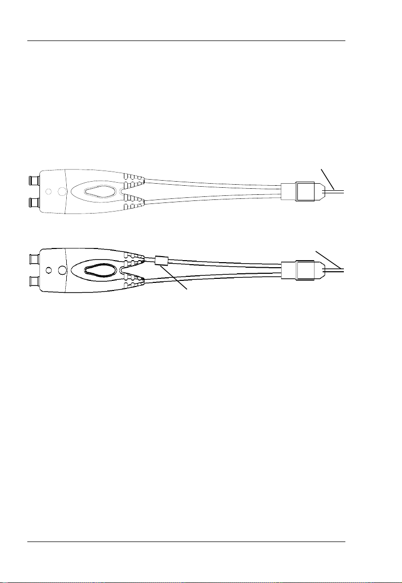
2. Solder-in Probe Head
The solder-in probe head includes two types: solder-in differential probe
head and solder-in single-ended probe head, as shown in Figure 5 and
Figure 6. Wherein, solder-in differential probe head is suitable for
measurement of high-density IC pin signals.
Figure 5 Solder-in Differential Probe Head
Figure 6 Solder-in Single-ended Probe Head
When using the solder-in probe head for measurement, please use an auxiliary
device to fix the probe head. Do not use your hand to fix the probe head, or
else, the lead resistor soldered onto the probe head might break or fall off.
What’s more, the hand-held position might also affect the probe performance.
The nickel wire of the solder-in probe head is a standard accessory. If the nickel
wire under use is damaged or broken, please replace it with an appropriate lead
resistor (refer to To Replace Probe Accessories).
Mark Sleeve of Negative Pole
Nickel Wire
Nickel Wire
Page 15

RIGOL
User Guide for PVA7000 Series Active Probe 9
To Use PVA7000 Series Active Probe
During the use of PVA7000 series active probe, correct operations can ensure
the probe performance, prolong the service life of the probe and ensure the
effectiveness of the signal measurement result. This chapter introduces in
detail the using method of the PVA7000 series active probe.
Main Topics:
⚫ To Connect to the Oscilloscope
⚫ To Use the Probe Head
⚫ To Replace Probe Accessories
⚫ To Adjust Offset Voltage
⚫ To Calibrate the Probe
Page 16

RIGOL
10 User Guide for PVA7000 Series Active Probe
To Connect to the Oscilloscope
After PVA7000 is connected correctly to a RIGOL MSO8000 series oscilloscope,
the oscilloscope recognizes the probe automatically and provides both power
and offset voltage to the probe. You can adjust the offset voltage (refer to To
Adjust Offset Voltage) and calibrate the probe (refer to To Calibrate the
Probe) by the front panel menu of the oscilloscope.
Please connect the probe to the oscilloscope following the steps below:
1. Connect the probe head (in the figure, taking a hand-held differential
probe head for example) with the active probe amplifier. If a single-ended
probe head is used, during the connection, pay attention to their polarities.
2. Connect the other end of the active probe amplifier to the channel input
connector of the oscilloscope and make sure the connection is tight.
3. Use any probe auxiliary device to connect the probe to the circuit to be
tested.
Page 17

RIGOL
User Guide for PVA7000 Series Active Probe 11
4. To disconnect the probe from the oscilloscope, press the button on the
probe (as shown in the left figure below), pull the connector straight out of
the oscilloscope (as shown in the right figure below) and then release the
button.
CAUTION
Do not twist the probe on the BNC connector of the oscilloscope.
Otherwise, the probe might be damaged.
Page 18

RIGOL
12 User Guide for PVA7000 Series Active Probe
To Use the Probe Head
In the Probe Head section, PVA7000 can be connected with 3 kinds of probe
heads. You can easily change the probe head by using the method introduced
in To Replace Probe Accessories. This chapter introduces how to use these
three kinds of probe heads respectively.
1. Hand-held Differential Probe Head
The hand-held differential probe head provides an effective bandwidth of more
than 2.5 GHz. The spacing between the two probe tips can be precisely
adjusted by turning the roller. The probe tips are replaceable, which can
prolong the service life of the probe.
The hand-held differential probe head can be used to measure differential and
single-ended signals. During the measurement, you can turn the roller on the
probe head to adjust the spacing between the probe tips so as to fit
measurements with different spacing requirements.
The structure of the hand-held differential probe head is shown in Figure 7.
Figure 7 Hand-held Differential Probe Head
① ② ③
Page 19

RIGOL
User Guide for PVA7000 Series Active Probe 13
① Turning the roller to adjust the spacing (0mm to 5.5mm) between the two
probe tips.
② Hand-held differential probe head .
③ 50Ω probe tip.
2. Solder-in Differential Probe Head
The solder-in differential probe head provides an effective bandwidth of more
than 2.5 GHz. The replacement of the nickel wire enhances the usability of the
probe and prolongs its service life.
The structure of the solder-in differential probe head is shown in Figure 8.
Figure 8 Solder-in Differential Probe Head
① Solder-in differential probe head.
② 0.2mm Nickel Wire.
When the points to be tested are widely spaced, the length of the nickel wire
will be increased. At this point, overshoot and ringing will occurs and the
high-frequency response will changes.
①
②
Page 20

RIGOL
14 User Guide for PVA7000 Series Active Probe
3. Solder-in Single-ended Probe Head
The solder-in single-ended probe head provides an effective bandwidth of more
than 2.5 GHz. The replacement of the nickel wire enhances the usability of the
probe and prolongs its service life.
The structure of the solder-in single-ended probe head is shown in Figure 9.
The pin at the same side with the negative pole mark sleeve (refer to Figure 6)
is negative.
Figure 9 Solder-in Single-ended Probe Head
① Solder-in single-ended probe head.
② 0.2mm Nickel Wire.
When the points to be tested are widely spaced, the length of the nickel wire
will be increased. At this point, overshoot and ringing will occur and the
high-frequency response will change.
①
②
Page 21

RIGOL
User Guide for PVA7000 Series Active Probe 15
To Replace Probe Accessories
1. To replace the probe head
Take care not to damage the connecting part to avoid affecting the probe
performance when replacing the probe head.
Replacing Method:
① Disconnect the current probe head from the active probe amplifier.
② Push the new probe head into the active probe amplifier straightly.
When single-ended probe head is used, pay attention to their
polarities.
2. To replace the probe tip
The probe tip and probe head are connected with screw thread, so please
note the screw rotation and strength when removing and installing the
probe tip.
3. To replace the nickel wire
If the nickel wire of the solder-in probe head under use becomes damaged
or breaks off, you can replace a new one. The probe head nickel wire
should satisfy the following size requirement, that is, the length must be
shorter than 5 mm.
Note: If the length of the nickel wire is longer than 5 mm, the bandwidth
specification of the probe will be affected. You can use the trim gauge to
measure and cut the nickel wire.
<5mm
Page 22

RIGOL
16 User Guide for PVA7000 Series Active Probe
To Adjust Offset Voltage
RIGOL MSO/DS7000/MSO8000 series oscilloscope can provide offset voltage
to the PVA7000 series active probe. The offset voltage adjusts the measured
signal which exceeds the input dynamic range of the probe to within an
appropriate range to ensure the measured signal’s integrity.
You can adjust the offset voltage by operating the front panel menu of the
oscilloscope. The operation method is as shown below.
1. Follow the instructions in To Connect to the Oscilloscope to connect
the PVA7000 series active probe to the channel input terminal (e.g. CH1)
of the MSO/DS7000/MSO8000 oscilloscope.
2. Open the probe offset voltage control menu of the
MSO/DS7000/MSO8000 oscilloscope (front panel operation: 1 → Probe
→ Bias Voltage) and rotate the knob to adjust the value.
Page 23

RIGOL
User Guide for PVA7000 Series Active Probe 17
To Calibrate the Probe
Before using, you should calibrate the PVA7000 series active probe. Follow the
procedures below to calibrate the PVA7000 active probe:
1. Connect the PVA7000 active probe to the analog channel (CH1 to CH4 of
the oscilloscope, illustrations here are based on CH1).
2. Open the probe calibration control menu (front panel operation: 1 →
Probe → Probe-Cal), and the oscilloscope starts to calibrate the probe.
The calibration will last for about 40 to 50 seconds. When the probe
calibration is finished, a prompt message "Probe calibration finished!" or
"Probe calibration failure!" is displayed in the user interface of the
oscilloscope.
Note: Technical specifications of the PVA7000 series active probe depend on
the calibration operation. After the calibration is finished, the DC gain, offset
voltage zero and offset gain will be calibrated. Users can query the information
about the manufacturer, model, serial number and the last calibration time of
the probe through the menu operation: 1 → Probe → Probe Info.
Page 24

RIGOL
18 User Guide for PVA7000 Series Active Probe
Care and Cleaning
Care
Do not place the probe and its accessories in places where they will be exposed
to sun light for long periods of time.
CAUTION
Keep the probe and its accessories away from any corrosive liquid.
Cleaning
Clean the probe and its accessories regularly according to their operation
conditions using the method below.
1. Disconnect the probe from the oscilloscope or power source.
2. Clean the external surfaces of the probe and its accessories with a soft
cloth dampened with mild detergent or water.
WARNING
To avoid short-circuit resulting from moisture or even personal
injuries, ensure that the probe is completely dry before use.
Page 25

RIGOL
User Guide for PVA7000 Series Active Probe 19
Warranty
RIGOL TECHNOLOGIES CO., LTD. (hereinafter referred to as RIGOL)
warrants that the product will be free from defects in materials and
workmanship within the warranty period. If a product proves defective within
the warranty period, RIGOL guarantees free replacement or repair for the
defective product.
To get repair service, please contact with your nearest RIGOL sales or service
office.
There is no other warranty, expressed or implied, except such as is expressly
set forth herein or other applicable warranty card. There is no implied warranty
of merchantability or fitness for a particular purpose. Under no circumstances
shall RIGOL be liable for any consequential, indirect, ensuing, or special
damages for any breach of warranty in any case.
Page 26

RIGOL
20 User Guide for PVA7000 Series Active Probe
Specifications
Technical Specifications
Item
PVA7250
Bandwidth
>2.5GHz
Rise Time
<140ps
System Bandwidth
2.5GHz
Input Capacitance
<1pF
Input Resistance
50kΩ±2% Differential
25kΩ±4% Single-ended
Input Dynamic Range
±2V
Input Common mode
Range
±6.25V DC to 100Hz
±1.25V >100Hz
Common Mode
Rejection Ratio
>45dB@1MHz
DC Attenuation
10:1 ±2%
Zero Offset Error
[1]
<30mV before calibration
<5mV after calibration
Offset Voltage Range
±2V
Offset Accuracy
[1]
<3% of current range
before calibration
<1% of current range
after calibration
Input Noise
3.8mVpp
Propagation Delay
7ns
Max Input Voltage
30V Peak CAT I
[2]
Electrostatic Protection
(HBM)
>8kV
Page 27

RIGOL
User Guide for PVA7000 Series Active Probe 21
General Characteristics
Environmental
Conditions
Operating
Non-operating
Temperature
+5°C to +40°C
-40°C to +60°C
Humidity
0 RH to 80% RH
0 RH to 90% RH
Altitude
4600m
15300m
Power Consumption
1.2W
N/A
Weights
147g±10g
[3]
530g±50g
[4]
Wire Length
1.4m
[1] Typical value. The specifications would change when different scales are
selected.
[2] CAT I and CAT II Definitions
Installation Category (Overvoltage Category) I: signal level, special
equipment or parts of equipment, telecommunication, electronic, etc.,
with smaller transient voltages than installation category (Overvoltage
Category) II.
Installation Category (Overvoltage Category) II: local level, appliance,
portable equipment etc., with smaller transient voltages than installation
category (Overvoltage Category) III.
[3] The weight of the PVA7000 probe with the hand-held differential probe
head.
[4] The weight of the PVA7000 series active probe kit with the probe bag.
 Loading...