

Page 1
© 2018 RIGOL (SUZHOU) TECHNOLOGIES INC. All Rights Reserved.
RIGOL
用户手册
User’s Guide
PLA2216 有源逻辑探头
PLA2216 Active Logic Probe
Page 2

一般安全概要
正确的连接与断开探头。
遵循所有终端额定值。
电源接通后,请勿接触外露的线路和元件。
怀疑产品出故障时,请勿进行操作。
切勿开盖操作。
请勿在易燃易爆的环境下操作。
请勿在潮湿的环境下操作。
请保持产品表面干燥。
请注意搬运安全。
- 1 -
Page 3
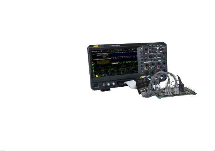
产品简介
PLA2216 是一款高性能有源逻
辑探头,可将待测系统上的数字
信号连接至 RIGOL MSO5000
系列数字示波器,实现逻辑分析
仪功能。
PLA2216 共有 16 个数字通道
(D0-D15),分为两个通道组
(D0-D7 和 D8-D15)。 每个数
字通道组均包含 信号 接口和地
接口,并且在探头输入端的标签
上,所有通道均用不同的数字清晰标示,以便于区分不同的通道。同时,
PLA2216 标配 16 根探头输入端信号引线和 16 根接地引线,可用于灵活的连
接被测信号和参考地。
- 2 -
Page 4
逻辑探头的使用方法
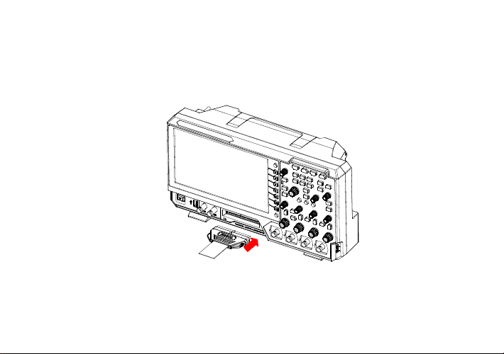
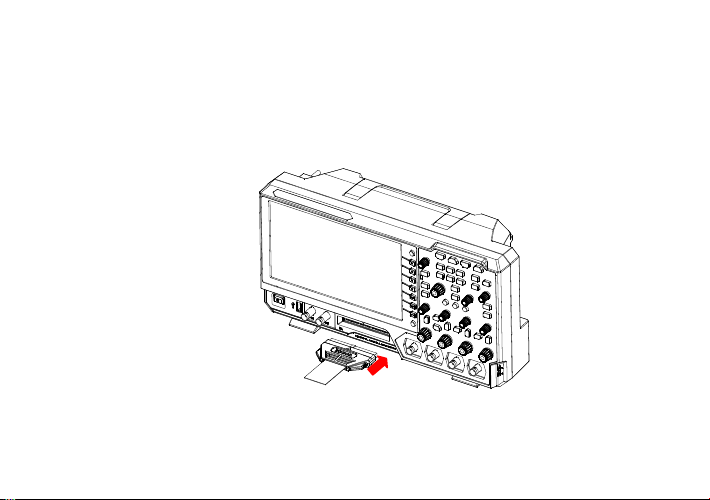
1. 连接 PLA2216 至示波器:将 PLA2216 探头输出端连接至示波器前面
板的数字信号输入端,如下图所示。
2. 连接被测信号至 PLA2216:用户可根据测试需求将任意数量(≤16)
的被测信号连接至 PLA2216 探头输入端。连接时需注意,输入信号的
- 3 -
Page 5
幅度不能超过探头的最大工作电压范围。PLA2216 提供两种与被测信号
的连接方式,以方便用户灵活探测信号。
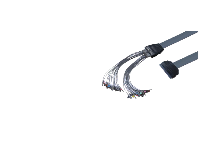
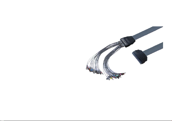
方法一:用户可通过输入端引线单独连接各个被测信号。通过输
入端引线上的通道标示以及探头输入端上的标签可方便地识别每
个信号所对应的通道号,如图 1 所示。
图 1
注意:使用过程中若出现串扰或地弹,可能是多通道共用地线导
致。因此建议您尽可能为每通道的信号线配一根地线并双绞。
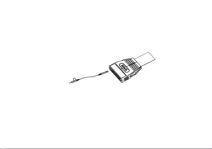
方法二:在方法一的基础上,将输入端引线与探头测试夹进行连
接,然后通过测试夹内的金属钩连接被测信号节点,如图 2 所示。
- 4 -
Page 6
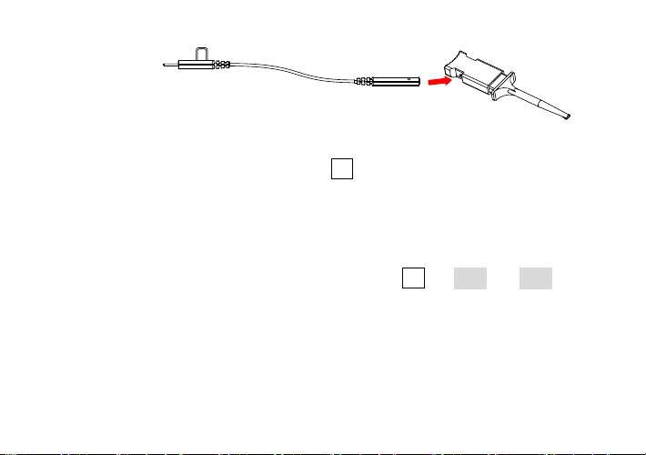
图 2
3. 设置探头:按示波器前面板上的 LA 键进入数字通道设置菜单,用户
可在该菜单下查看和设置如下参数:阈值电平(D7-D0 与 D15-D8 分组
阈值电平独立调节)、波形大小(应用于所有通道,其中“大”选项只在
屏幕活动通道数不多于 8 时可用)和通道标签等。
注意:若探头第一次连接到该示波器或者环境温度变化 5℃以上,建议
利用 LA 菜单下校准功能进行零点校准(按 LA 阈值 校准),校
准时保持 PLA2216 输入端不接信号。
4. 功能检查:完成上述操作后,被测信号将显示在示波器屏幕上相应的数
字通道上。若看不到信号,请调节示波器选择合适的触发源、触发电平
和触发方式等常规设置。若仍然看不到信号,请再次检查电气连接和参
数设置,或尝试使用其他探头(如模拟探头)来验证测试点的信号状态。
- 5 -
Page 7

探头指标
输入通道数
16
阈值范围
± 15 V
阈值精度
± (100 mV+3%的阈值设置)
最大输入电压
± 40 V(峰值)
最大输入动态范围
± 10 V+阈值
最小电压摆动
500 mVpp
最小可检测脉宽
5 ns
输入阻抗
约 101 kΩ
输入电容
约 8 pF
探头主缆长度
约 90 cm
输入端引线长度
约 25 cm
操作环境
0℃~50℃,0~80%RH
存放环境
-20℃~60℃,0~90%RH
- 6 -
Page 8

附件
编号
名称描述
数量
1
主线
1
2
引线
32 (2× 16)
3
探头钩
32
4
中英文用户手册
1
5
PLA2216 包装盒
1
- 7 -
Page 9

附件示意图
主线 引线 探头钩
联系我们
如您在使用此产品或本手册的过程中有任何问题或需求,可与 RIGOL 联系:
电子邮箱:service@rigol.com
网址:www.rigol.com
- 8 -
Page 10

Page 11

General Safety Summary
Connect and disconnect the probe properly.
Observe all terminals ratings.
Do not touch exposed connections and components after power on.
Do not operate with suspected failures.
Do not operate without covers.
Do not operate in an explosive atmosphere.
Do not operate in wet conditions.
Keep product surface clean and dry.
Pay attention to handling safety.
- 1 -
Page 12
Product Overview
Being a high-performance active
logic probe, PLA2216 connects
the digital signals under test to
the MSO5000 series digital
oscilloscope to realize the logic
analyzer function.
The 16 digital channels (D0-D15)
of PLA2216 are divided into two
channel groups (D0-D7 and
D8-D15) each of which includes
signal interfaces and ground interfaces. All the channels are marked with
different numbers on the label of the probe input to identify different
channels. PLA2216 provides 16 input signal leads and 16 ground leads to
realize flexible connection of signals and reference ground.
- 2 -
Page 13
The Using Method of the Logic Probe
1. Connect PLA2216 to the oscilloscope: connect the probe output
to the digital signal input terminal at the front panel of the oscilloscope
as shown in the figure below.
2. Connect the signals under test to PLA2216: users can connect
any number (≤16) of the signals under test to PLA2216 probe input
- 3 -
Page 14

according to the test need. Note that the amplitude of the input signal
should not exceed the maximum working voltage range of the probe.
PLA2216 provides two connection methods to realize convenient and
flexible detection.
Method one: users can connect the signals under test through
the probe leads separately. You can easily identify the
corresponding channel of each signal by the channel label on the
probe leads and the label of the probe input, as shown in Figure
1.
Figure 1
Note: If crosstalk or ground bounce occurs during use, it might
be caused when channels share a single ground lead. So you are
- 4 -
Page 15

recommended to add a ground wire to the signal lines of each
channel and twist them.
Method two: on the basis of method one, you can connect a
grabber to each lead and connect it to the device under test as
shown in Figure 2.
Figure 2
3. Set the probe: press LA at the front panel of the oscilloscope to
enter the digital channel setting menu. Users can view and set the
following parameters under this menu: threshold level (the threshold
levels of D7-D0 and D15-D8 can be adjusted independently),
waveform size (applicable to all the channels; wherein, item Large is
- 5 -
Page 16

only available when the number of active channels is no more than 8),
channel label and so on.
Note: When the probe is connected to the oscilloscope for the first
time or the temperature change is more than 5 degrees, you are
recommended to calibrate the probe zero using the calibration
function in the LA menu (press LA Threshold Calibration) and
please disconnect all the connections to the PLA2216 input terminal
during the calibration.
4. Function Check: after finishing the above operations, the signal
under test will be displayed on the corresponding digital channel on
the oscilloscope screen. If no signal is displayed, please adjust the
oscilloscope to select proper general settings (such as the trigger
source, trigger level and trigger mode). If signal is still not displayed,
please check the electric connection and parameter settings again or
please try to use other probe (such as analog probe) to check the
signal state of the test point.
- 6 -
Page 17

Probe Specifications
Input channels
16
Threshold range
± 15 V
Threshold accuracy
± (100 mV + 3% of threshold setting)
Max input voltage
± 40 V (peak)
Max input dynamic range
± 10 V + threshold setting
Min voltage swing
500 mVpp
Min detectable pulse width
5 ns
Input impedance
About 101 kΩ
Input capacitance
About 8 pF
Cable length
About 90 cm
Lead length
About 25 cm
Operation environment
0℃~50℃, 0~80%RH
Storage environment
-20℃~60℃, 0~90%RH
- 7 -
Page 18

Accessories
Item
Description
Quantity
1
Main Cable
1
2
Lead
32 (2× 16)
3
Grabber
32 4 Chinese and English User’s Guide
1 5 PLA2216 Packing Box
1
- 8 -
Page 19
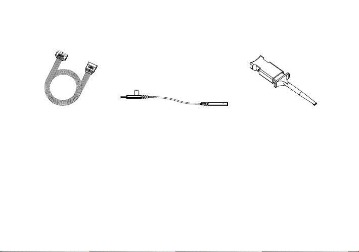
Accessories Sketch Map
Main Cable Lead Grabber
Contact Us
If you have any problem or requirement when using our products or this
manual, please contact RIGOL.
E-mail:service@rigol.com
Website:www.rigol.com
- 9 -
Page 20

ZN1 02 0 00 4 4 3 8
UGE29X00-1110
Oct. 2018
 Loading...