


User Guide
MSO5000-E Series Digital
Oscilloscope
Sept. 2019
RIGOL (SUZHOU) TECHNOLOGIES INC.


RIGOL
Guaranty and Declaration
Copyright
© 2019 RIGOL (SUZHOU) TECHNOLOGIES INC. All Rights Reserved.
Trademark Information
RIGOL is a registered trademark of RIGOL (SUZHOU) TECHNOLOGIES INC.
Publication Number
UGA28101-1110
Software Version
00.01.01.00.03
Software upgrade might change or add product features. Please acquire the latest
version of the manual from RIGOL website or contact RIGOL to upgrade the
software.
Notices
RIGOL produ cts are cove red by P.R.C. and f oreign pa tents, issue d and pendin g.
RIGOL reserves the right to modify or change parts of or all the specifications
and pricing policies at the company’s sole decision.
Information in this publication replaces all previously released materials.
Information in this publication is subject to change without notice.
RIGOL shall not be liable for either incidental or consequential losses in
connection with the furnishing, use, or performance of this manual, as well as
any information contained.
Any part of th is d ocu ment is f orbi dden to be c opie d, ph oto copie d, o r rea r ran ged
without prior written approval of RIGOL.
Product Certification
RIGOL guarantees that this product conforms to the national and industrial
standards in China as well as the ISO9001:2015 standard and the ISO14001:2015
standard. Other international standard conformance certifications are in progress.
Contact Us
If you have any problem or requirement when using our produ cts or this man ual,
please contact RIGOL.
E-mail: service@rigol.com
Website: www.rigol.com
MSO5000-E User Guide I

RIGOL
Safety Requirement
General Safety Summary
Please review the following safety pre cautio ns ca refully before putting the
instrument into operation so as to avoid any personal injury or damage to the
instrument and any product connected to it. To prevent potential hazards, please
follow the instructions specif ied in this manual to use the instrument properly.
Use Proper Power Cord.
Only the exclusive power cord designed for the instrument and authorized for use
within the local country could be used.
Ground the Instrument.
The instrument is grounded th rou gh t he Protective Earth lead of the p ower cord. To
avoid electric shock, connect the earth terminal of the power cord to the Protective
Earth terminal before connecting any input or output terminals.
Connect the Probe Correctly.
If a probe is used, the probe ground lead must be connected to earth ground. Do not
connect the ground lead to high voltage. Impr oper w a y of conne ction coul d r esult in
dangerous voltages being present on the connectors, controls or other surfaces of
the oscilloscope and probes, which will cause potential hazards for operators.
Observe All Terminal Ratings.
To avoid fire or shock hazard, observe al l ratin gs and mark ers on the instrume nt and
check your manual for more information about ratings before connecting the
instrument.
Use Proper Overvoltage Protection.
Ensure that no over voltage (su ch as that caused b y a b olt of lig htning) can reach the
product. Otherwise, the operator might be exposed to the danger of an electric
shock.
Do Not Operate Without Covers.
Do not operate the instrument with covers or panels removed.
Do Not Insert Objects Into the Air Outlet.
Do not insert anything into the holes of the fan to avoid damaging the instrument.
Use Proper Fuse.
Please use the specified fuses.
II MSO5000-E User Guide

RIGOL
Avoid Circuit or Wire Exposure.
Do not touch exposed junctions and components when the unit is powered on.
Do Not Operate With Suspected Failures.
If you suspect that any damage may occur to the instrument, have it inspected by
RIGOL authorized personnel before further operations. Any maintenance,
adjustment or replacement especially to circuits or accessories must be performed
by RIGOL authorized personnel.
Provide Adequate Ventilation.
Inadequate ventilation may cause an increase of temperature in the instrument,
which would cause damage to the instrument. So please keep the instrument well
ventilated and inspect the air outlet and the fan regularly.
Do Not Operate in Wet Conditions.
To avoid short circuit inside the instrument or electric shock, never operate the
instrument in a humid environment.
Do Not Operate in an Explosive Atmosphere.
To avoid personal injuries or damage to the instrument, never operate the
instrument in an explosive atmosphere.
Keep Product Surfaces Clean and Dry.
T o a void dust or moisture from af fecting the pe rformance of the inst rument, keep th e
surfaces of the instrument clean and dry.
Prevent Ele c tr o static Impact.
Operate the instrume nt i n an el ectr ostatic dischar ge protectiv e e nvi ron ment to a void
damage induced by static discharges. Always ground both the internal and external
conductors of cables to release sta t i c be fore making connections.
Use the Battery Properly.
Do not expose the battery (if available) to high temperature or fire. Keep it out of the
reach of children. Improper change of a battery (lithium battery) may cause an
explosion. Use the RIGOL specified battery only.
Handle with Caution.
Please handle with care during transportation to avoid damage to keys, knobs,
interfaces, and other parts on the panels.
MSO5000-E User Guide III
RIGOL
WARNING
avoided, will result in serious injury or death.
CAUTION
avoided, could result in damage to the product or loss of important data.
DANGER
It calls attention to an operation, if not correctly performed, could
result in injury or hazard immediately.
WARNING
It calls attention to an operation, if not correctly performed, could
result in potential injury or hazard.
CAUTION
It calls attention to an operation, if not correctly performed, could
product.
Hazardous
Voltage
Safety Warning
Protective Earth
Terminal
Chassis Ground
Test Ground
Safety Notices and Symbols
Safety Notic e s in this Manual:
Indicates a potentially hazardous situation or practice which, if not
Indicates a potentially hazardous situation or practice which, if not
Safety Terms on the Product:
result in damage to the product or other devices connected to the
Safety Symbols on the Product:
IV MSO5000-E User Guide
RIGOL
WARNING
measurement categories.
WARNING
keep the instrument well v entilat ed and ins pect the a ir outlet an d the fan
regularly.
Measurement Category
Measurement Category
MSO5000-E series digital oscilloscopes can make m e asurements in Measurement
Category I.
This oscilloscope can only be used for measurements within its specified
Measurement Category Definitions
Measurement category I is for measurements performed on circuits not directly
connected to MAINS. Examples are measurement s on circuits not derived from
MAINS, and specially protected (internal) MAINS derived circuits. In the latter case,
transient stresses are variable. Thus, you must know the transient withstand
capability of the equipment.
Measurement category II is for measurements performed on circuits directly
connected to low voltage installation. Examples are measurements on household
appliances, portable tools and similar equipment.
Measurement category III is fo r measure ments perf ormed in the b uilding inst allation.
Examples are measurements on distribution boards, circuit-breakers, wiring
(including cables, bus-bars, junction box es, switches and so cket -outlets) in th e fixed
installation, and equipment for industrial use and some other equipment. For
example, stationary motors with permanent connection to a fixed installation.
Measurement category IV is for measurements performed at the source of a
low-voltage installation. Examples are electricity meters and measurements on
primary overcurrent protection devices and ripple control units.
Ventilation Requirement
This oscilloscope uses a fan t o for ce cooling. Please make sure that the air i ntake an d
exhaust areas are free from obstructions and have free air. When using the
oscilloscope in a bench-top or rack setting, provide at least 10 cm clearance beside,
above and behind the instrument for adequate ventilation.
Inadequate ventilation may cause an increase of temperature in the
instrument, which would cause damage to the instrument. So please
MSO5000-E User Guide V
RIGOL
WARNING
operate the instrument in a humid environment.
WARNING
danger of an electric shock.
Working Environment
Temperature
Operating : 0℃ to + 50℃
Non-operating: -30℃ to + 70℃
Humidity
Operating:
Below + 30℃: ≤95% RH (without condensation)
+ 30℃ to + 40℃: ≤75% RH (without condensation)
+ 40℃ to + 50℃: ≤45% RH (without condensation)
Non-operating:
Below 65℃: ≤95% RH (without condensation)
To avoid short circuit inside the instrument or electric shock, never
Altitude
Operating: below 3 km
Non-operating: below 15 km
Installation (Overvoltage) Category
This product is powered by mains conforming to installation (overvoltage) category
II.
Ensure that no overvoltage (such as that caused by a bolt of lightning)
can reach the product. Otherwise, the operator might be exposed to the
Installat io n (Overvolta g e ) Cate g o ry Definitions
Installation (overvoltage) category I refers to signal level which is applicable to
equipment measurement terminals connected to the source circuit. Among these
terminals, precautions are done to limit the transient voltage to a low level.
Installation (overvoltage) category II refers to the local power distribution level
which is applicable to equipment connected to the AC line (AC power).
Pollution Degree
Pollution Degree 2
Pollution Degree Definition
Pollution Degree 1: No pollution or only dry, nonconductive pollution occurs. The
pollution has no effect. For example, a clean room or air-con ditioned office
VI MSO5000-E User Guide
RIGOL
CAUTION
WARNING
supply.
environment.
Pollution Degree 2: Normally only nonconductive pollution occurs. Temporary
conductivity caused by condensation is to be expected. For example, indoor
environment.
Pollution Degree 3: Conductive pollution or dry nonconductive pollution that
becomes conductive due to condensation occurs. To be found in industrial
environment or construction sites (harsh environments). For example, sheltered
outdoor environment.
Pollution Degree 4: The pollution generates persistent conductivity caused by
conductive dust, rain, or snow.
For example, outdoor areas.
Safety Class
Class 1 – Grounded Product
Care and Cleaning
Care
Do not store or leave the instrument where it may be exposed to direct sunlight for
long periods of time.
Cleaning
Clean the instrument regularly according to its operating conditions.
1. Disconnect the instrument from all power sources.
2. Clean the ex ter nal su rfaces of th e instrument with a soft cloth dampened with
mild detergent or water. Avoid having an y water or other o bjects into the chassis
via the heat dissipation hole. When cleaning the LCD, take care to avoid
scarifying it.
MSO5000-E User Guide VII
To avoid damage to the instrument, do not expose it to caustic liquids.
To avoid short-circuit resulting from moisture or personal injuries, ensu re
that the instrument is completely dry before connecti ng it to the power

RIGOL
Environmental Consideratio ns
The following symbol indicates that this product complies with the WEEE Directive
2002/96/EC.
Product End-of-Life Handling
The equipment may contain substances that could b e harmf ul to t he environment or
human health. To avoid the release of such substances into the environment and
avoid harm to human health, we recommend you to recycle this product
appropriately to ensure that most materials are reused or recycled properly. Please
contact your local authorities for disposal or recycling information.
You can click on the following link
http://www.rigol.com/Files/RIGOL_RoHS2.0&WEEE.pdf to down load the latest
version of the RoHS&WEEE certification file.
VIII MSO5000-E User Guide

RIGOL
MSO5000-E Series Overview
MSO5000-E series digital oscilloscope is a high-performance oscilloscope mod el
designed based on RIGOL UltraVision II technology. With a 9-inch capacitive
multi-touch screen, the MSO5000-E series integrates 7 independent instrument s into
one, delivering super sample ban dwidth ratio, extreme l y high memory dept h, and
other excellent specifications. It is compact an d portable in design, and all of the
MSO series products support multiple channels, and the upgrade of the analysis
software. As it integrates many functions of multiple instruments, different user
groups can have more choices in selecting their desired product based on their needs,
helping them save their budget to a large extent while enjoying the superior test
support and user experience.
Main Features:
Analog bandwidth: 150 MHz
2 analog channels, 1 EXT channel, standard configuration of 16 di gital channe ls
(probe option is required to be ordered)
Up to 4 GSa/s real-time sample rate
Up to 100 Mpts memory de pt h (option)
High waveform capture rate (over 300,000 wfm/s)
Auto measurement of 41 waveform parameters; full-memory hardware
measurement function
A variety of serial protocol triggers and decodes
Up to 450,000 fra mes of hardware real-time an d ceaseless wav eforms recording
and playing functions
Independent search, navigation keys, and event table
Built-in advanced power analysis software (option)
Integrates 7 independent instruments into 1, including a digital oscilloscope, a
logic analyzer, a spectrum analyzer, an Arbitra ry Wave form Generato r, a digital
voltmeter, a frequency counter and totalizer, and a protocol analyzer
9-inch capacitive multi-touch screen, 256-level intensity grading display, with
color persistence
Multiple interfaces av ail able: USB HOST & DEVI CE , LAN(LXI) , HDMI, TRIG OUT,
and USB-GPIB
Web Control remote command
Unique online version upgrade
Novel and delicate industrial design, easy to operate
MSO5000-E User Guide IX

RIGOL
Document Overview
Main Topics of this Manual:
Chapter 1 Quick Start
Introduces the preparations before using the oscilloscope and provides a basic
introduction of the instrument.
Chapter 2 To Set the Vertical System
Introduces the vertical system functions of the oscilloscope.
Chapter 3 To Set the Horizontal System
Introduces the horizontal system functions of the oscilloscope.
Chapter 4 To Set the Sample System
Introduces the sample system functions of the oscilloscope.
Chapter 5 To Trigger the Oscilloscope
Introduces the trigger mode, trigger coupling, trigger holdoff, external trigger, and
various trigger types of the oscilloscope.
Chapter 6 Operations and Measurements
Introduces how to make math operation, auto measurement, and cursor
measurement.
Chapter 7 Digital Voltmeter (DVM) and Frequency Counter
Introduces how to use the digital voltmeter and the frequency counter.
Chapter 8 Power Analysis (Option)
Introduces the power quality and output ripple noise of the input power.
Chapter 9 Histogram Analysis
Introduces the histogram analysis function.
Chapter 10 Digital Channel
Introduces how to use the digital channels of the mixed signal digital oscilloscope.
Chapter 11 Protocol Decoding
Introduces how to decode the input signal by using those common protocols.
Chapter 12 Reference Waveform
Introduces how to compare the input waveform with the reference waveform.
Chapter 13 Pass/Fail Test
Introduces how to monitor the input signal by using the Pass/Fail test.
X MSO5000-E User Guide

RIGOL
Chapter 14 Waveform Recording & Playing
Introduces the waveform recording & playing function.
Chapter 15 Search and Navigation Function
Introduces the navigation function and how to quickly search the relevant events.
Chapter 16 Display Control
Introduces how to control the display of the oscilloscope.
Chapter 17 Function/Arbitrary Waveform Generator (Option)
Introduces how to use the built-in Function/Arbitrary Waveform Generator option.
Chapter 18 Store and Load
Introduces how to store and load the measurement results and the setting of the
oscilloscope.
Chapter 19 System Utility Function Setting
Introduces how to set the remote interfaces and system-related functions.
Chapter 20 Remote Control
Introduces h ow t o control the oscill oscope remotel y.
Chapter 21 Troubleshooting
Introduces how to deal with the common failures of the oscill os cope.
Chapter 22 Appendix
Provides the basic information for the options and accessories.
MSO5000-E User Guide XI
RIGOL
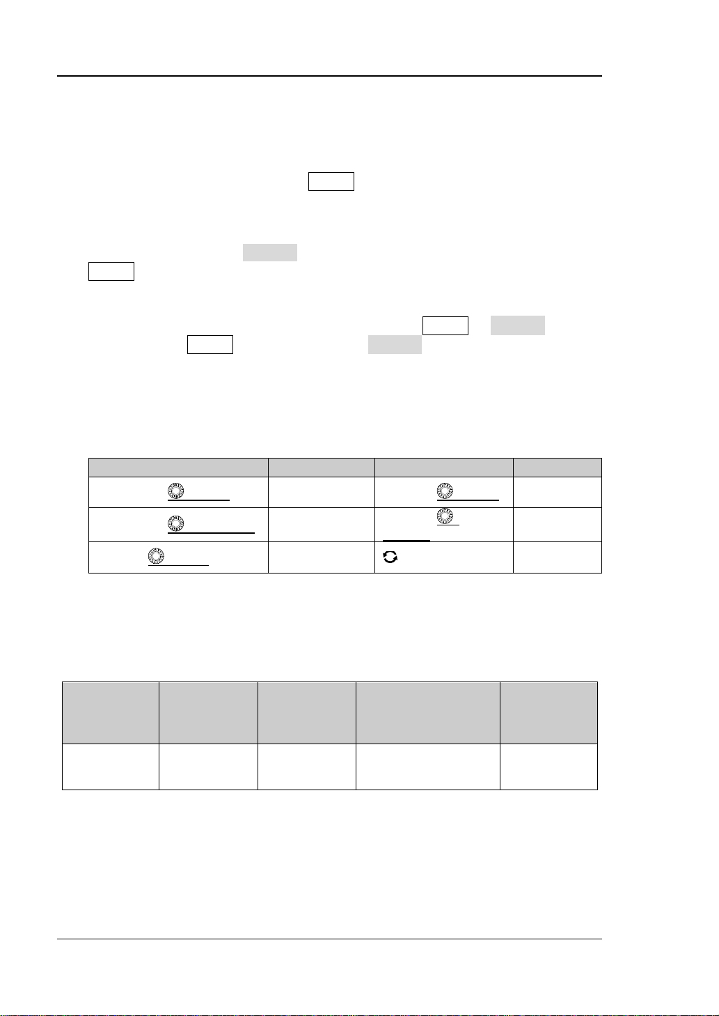
Label
Knob
Label
Knob
Horizontal
Timebase Knob
Vertical Scale
Knob
Horizontal
OFFSET
Vertical
Trigger Level
Knob
Multifunction
Knob
No. of
Generator Channels
16 (Required
the probe)
Format Conventions in this Manual:
1. Key
The key on the front panel is denoted by the format of "K ey Name (Bold) + Text
Box" in the manual. For example, Utility denotes the "Utility" key.
2. Menu
The menu items are denoted by the format of "Menu Word (Bold) + Character
Shading". For example, System denotes the "System" menu item under
Utility.
3. Operation Procedures:
denotes the next ste p of o perat ion. F or e xample, Utility System denotes
that first press Utility, and then press the System key.
4. Connector:
The connectors on the front or rear panel are usually denoted by the format of
"Connector Name (Bold) + Square Bra ckets (Bold)". F or exam ple, [TRIG OUT].
5. Knob
Horizontal SCALE
Horizontal POSITION
Trigger LEVEL
Position Knob
Vertical SCALE
Vertical
Offset Knob
Content Conventions in this Manual:
MSO5000-E series includes the followin g models. U nle ss othe rwise s pecified, this
manual takes MSO5152-E as an example to illustrate the functions and operation
methods of MSO5000-E series.
Model
MSO5152-E 150 MHz 2 1, Opt.
Max. Analog
Bandwidth
No. of Analog
Channels
Function/Arbitrary
Waveform
No. of Digital
Channels
to purchase
Manuals of this Product:
Quick Guide, User Guide, Prog rammin g Guide, Data sheet, etc. F or the lat est v ersion
of this manual, download it from the official website of RIGOL (www.rigol.com).
XII MSO5000-E User Guide

Contents RIGOL
Contents
Guaranty and Declaration ......................................................................... I
Safety Requirement ................................................................................ II
General Safety Summary ........................................................................... II
Safety Not ices and Symbol s ...................................................................... IV
Measurement Category ............................................................................. V
Ventilation Requirement ............................................................................ V
Working Enviro nment .............................................................................. VI
Care and Cleaning .................................................................................. VII
Environmental Considerations ................................................................. VIII
MSO5000-E Series Overview .................................................................. IX
Document Overview ................................................................................. X
Chapter 1 Quick Start ....................................................................... 1-1
General Inspection ................................................................................ 1-2
Appearance and Dimensions ................................................................... 1-3
To Prepa re for Use ................................................................................. 1-4
To Adjust the Supporting Legs .......................................................... 1-4
To Conne ct to AC Power .................................................................. 1-4
Turn-on Checkout ........................................................................... 1-5
To Connect the Probe ...................................................................... 1-5
Function Inspection ......................................................................... 1-8
Probe Compensation ....................................................................... 1-9
Front Panel Overview ............................................................................ 1-10
Rear Panel Overview ............................................................................. 1-11
Front Panel Function Overview............................................................... 1-13
Vertical ......................................................................................... 1-13
Horizontal ..................................................................................... 1-14
Trigger .......................................................................................... 1-15
Function Menu ............................................................................... 1-15
Navigation Control Ke y ................................................................... 1-16
Quick Key (Shortcut Key) ................................................................ 1-16
Function/Arbitrary Waveform Generator Setting ................................ 1-16
Clear ............................................................................................ 1-17
Auto ............................................................................................. 1-17
RUN/STOP .................................................................................... 1-17
Single ........................................................................................... 1-17
Touch Lock Key .............................................................................. 1-17
Default ......................................................................................... 1-17
Multifunction Knob ......................................................................... 1-18
User Interface ...................................................................................... 1-19
Touch Screen Controls .......................................................................... 1-22
Tap ............................................................................................... 1-23
MSO5000-E User Guide XIII

RIGOL Contents
Pinch & Stretch ............................................................................. 1-23
Drag ............................................................................................. 1-23
Rectangle Drawing ......................................................................... 1-24
Parameter Setting Method ..................................................................... 1-26
To Use the Kensington Security Loc k ...................................................... 1-27
To Use the Built-in Help System ............................................................. 1-28
To View the Option Information and the Option Installation ...................... 1-29
Chapter 2 To Set the Vertical System ............................................... 2-1
To Enable or Disable the Analog Channel .................................................. 2-2
To Adjust the Vertical Scale ..................................................................... 2-3
Vertical Expansion .................................................................................. 2-4
To Adjust the Vertical Offset .................................................................... 2-4
Channel Coupling ................................................................................... 2-5
Bandwidth Limit ..................................................................................... 2-5
Probe Ratio ........................................................................................... 2-6
Input Impe da nce ................................................................................... 2-7
Waveform Invert .................................................................................... 2-7
Amplitude Unit ....................................................................................... 2-8
Channel Delay ....................................................................................... 2-8
Offset Cal .............................................................................................. 2-9
Channel Label ........................................................................................ 2-9
Chapter 3 To Set the Horizontal System ........................................... 3-1
To Adjust the Horizontal Timebase ........................................................... 3-2
To Adjust the Horizontal Position.............................................................. 3-3
Delayed Sweep ...................................................................................... 3-4
Chapter 4 To Set the Sample System ................................................ 4-1
Timebase Mode ..................................................................................... 4-2
YT Mode ......................................................................................... 4-2
XY Mode ......................................................................................... 4-2
ROLL Mode ..................................................................................... 4-4
Acquisition Mode .................................................................................... 4-5
Normal ........................................................................................... 4-5
Average .......................................................................................... 4-5
Peak ............................................................................................... 4-6
High Resolution ............................................................................... 4-6
Sampling Mode ...................................................................................... 4-7
Sample Rate .......................................................................................... 4-7
LA Sample Rate ..................................................................................... 4-9
Memory Depth ....................................................................................... 4-9
LA Memory De pth ................................................................................ 4-10
Anti-Aliasing ........................................................................................ 4-10
Horizontal Expansion ............................................................................ 4-11
Chapter 5 To Trigger the Oscilloscope .............................................. 5-1
Trigger Source ....................................................................................... 5-2
XIV MSO5000-E User Guide

Contents RIGOL
Trigger LEVEL/Threshold Level ................................................................ 5-3
Trigger Mode ........................................................................................ 5-4
Trigger Coupling .................................................................................... 5-5
Trigger Holdoff ...................................................................................... 5-6
Noise Rejection ..................................................................................... 5-7
Trigger Type ......................................................................................... 5-8
Edge Trigger ................................................................................... 5-9
Pulse Trigger ................................................................................. 5-10
Slope Trigger ................................................................................. 5-12
Video Trigger ................................................................................. 5-15
Pattern Trigger .............................................................................. 5-17
Duration Trigger ............................................................................ 5-19
Timeout Trigger ............................................................................. 5-22
Runt Trigger .................................................................................. 5-23
Window Trigger ............................................................................. 5-25
Delay Trigger ................................................................................. 5-27
Setup/Hold Trigger ......................................................................... 5-29
Nth Edge Trigger............................................................................ 5-31
RS232 Trigger (Option) ................................................................... 5-32
I2C Trigger (Option) ....................................................................... 5-35
SPI Trigger (Option) ....................................................................... 5-37
CAN Trigger (Option) ...................................................................... 5-39
FlexRay Trigger (Option) ................................................................. 5-42
LIN Trigger (Option) ....................................................................... 5-44
I2S Trigger (Option) ....................................................................... 5-46
MIL-STD-1553 Trigger (Op tion) ....................................................... 5-49
Zone Trigger ........................................................................................ 5-52
Trigger Output Connector ...................................................................... 5-53
Chapter 6 Operations and Measurements ......................................... 6-1
Math Operation ..................................................................................... 6-2
Addition ......................................................................................... 6-2
Subtraction .................................................................................... 6-3
Multiplication .................................................................................. 6-4
Division .......................................................................................... 6-5
FFT ............................................................................................... 6-6
"AND" Operation ............................................................................ 6-10
"OR" Operation .............................................................................. 6-11
"XOR" Operation ............................................................................ 6-12
"NOT" Operation ............................................................................ 6-13
Intg .............................................................................................. 6-14
Diff ............................................................................................... 6-15
Sqrt .............................................................................................. 6-16
Lg (Base 10 Exponential) ................................................................ 6-17
Ln ................................................................................................ 6-18
Exp .............................................................................................. 6-19
MSO5000-E User Guide XV

RIGOL Contents
Abs .............................................................................................. 6-20
Low Pas s ...................................................................................... 6-21
High Pass ...................................................................................... 6-22
Band Pass ..................................................................................... 6-23
Band Stop ..................................................................................... 6-24
AX+B ........................................................................................... 6-25
Math Operation Label ..................................................................... 6-26
Auto Measurement ............................................................................... 6-27
Quick Measurement after AUTO ...................................................... 6-27
Measurement Parameter ................................................................ 6-29
Measurement Settings .................................................................... 6-35
Remove the Measurement Result .................................................... 6-38
Statistical Function ......................................................................... 6-38
All Measurement ............................................................................ 6-39
Cursor Measurement ............................................................................ 6-39
Manual Mode ................................................................................ 6-41
Track Mode ................................................................................... 6-45
XY Mode ....................................................................................... 6-47
Measure Mode ............................................................................... 6-49
Chapter 7 Digital Voltmeter (DVM) and Frequency Counter ............. 7-1
Digital Voltmeter (DVM) .......................................................................... 7-2
To Enable or Disable DVM Measurement ............................................ 7-2
To Select the Measurement Source .................................................... 7-2
To Select Measurement Mode ........................................................... 7-3
To Set the Limits ............................................................................. 7-3
Frequency Counter ................................................................................. 7-4
To Enable or Disable the Frequency Counter ....................................... 7-4
To Select the Measurement Source .................................................... 7-4
To Select the Measurement Item ....................................................... 7-4
To Set Resolution ............................................................................. 7-5
To Clear Count ................................................................................ 7-5
To Enable or Disable the Statisti cal Function ....................................... 7-5
Chapter 8 Power Analysis (Option) .................................................. 8-1
Power Quality ........................................................................................ 8-2
Ripple ................................................................................................... 8-4
Chapter 9 Histogram Analysis .......................................................... 9-1
To Enable or Disable the Histogram Function ............................................ 9-2
To Select the Histogram Type .................................................................. 9-2
To Select the Histogram Source ............................................................... 9-3
To Set the Histogram Height ................................................................... 9-3
To Set the Histogram Range .................................................................... 9-3
To Enable or Disable the Statisti cal Function ............................................. 9-3
To Reset ................................................................................................ 9-4
Chapter 10 Digital Channel............................................................... 10-1
XVI MSO5000-E User Guide

Contents RIGOL
To Select the Digital Channel ................................................................. 10-2
To Enable/Disable the Digital Channel ..................................................... 10-2
To Set the Threshold and Calibrate Probe ............................................... 10-3
Auto Arrangement Setting ..................................................................... 10-4
To Set the Waveform Display Size .......................................................... 10-4
To Set the Label ................................................................................... 10-4
Group Setti ng ...................................................................................... 10-5
Waveform Color of the Digital Channel ................................................... 10-6
Chapter 11 Protocol Decoding .......................................................... 11-1
Parallel Decoding .................................................................................. 11-2
RS232 Decodi n g (Option) ...................................................................... 11-7
I2C Decoding (Option) ........................................................................ 11-14
SPI Decoding (Option) ........................................................................ 11-18
LIN Decoding (Option) ........................................................................ 11-23
CAN Decoding (Option) ....................................................................... 11-28
FlexRay Decoding (Option) .................................................................. 11-33
I2S Decodin g (Option) ........................................................................ 11-37
1553B Decoding (Option) .................................................................... 11-41
Chapter 12 Reference Waveform ...................................................... 12-1
To Enable Ref Function ......................................................................... 12-2
To Select the Reference Channel ............................................................ 12-2
To Select the Ref Source ....................................................................... 12-2
To Adjust the Ref Waveform Display ....................................................... 12-2
To Save to Internal Memory .................................................................. 12-3
To Clear the Display of the Reference Waveform ...................................... 12-3
To View Details of the Reference Waveform ............................................ 12-3
To Reset the Reference Waveform .......................................................... 12-4
Color Setting ........................................................................................ 12-4
Label Setting ........................................................................................ 12-4
To Export to Internal or External Memory ............................................... 12-5
To Import from Internal or External Memory ........................................... 12-5
Chapter 13 Pass/ Fail Te st ................................................................. 13-1
To Enable or Disable the Pass/Fail Test Function ...................................... 13-2
To Start or Stop the Pass/Fail Test Operation ........................................... 13-2
To Select the Source ............................................................................. 13-2
To Create a Mask.................................................................................. 13-3
To Save the Mask ................................................................................. 13-3
To Load a Mask .................................................................................... 13-3
To Set the Output Form of the Test Results ............................................. 13-4
To Enable or Disable the Display of the Statistics of the Test Results .......... 13-5
Statistics Reset ..................................................................................... 13-5
Chapter 14 Waveform Recording & Playing ...................................... 14-1
Common Settings ................................................................................. 14-2
Record Options .................................................................................... 14-3
MSO5000-E User Guide XVII

RIGOL Contents
Play Options ........................................................................................ 14-4
Chapter 15 Search and Navigation Function ..................................... 15-1
Search Function ................................................................................... 15-2
Navigation Function .............................................................................. 15-4
Chapter 16 Display Control ............................................................... 16-1
To Select the Display Type .................................................................... 16-2
To Set the Persistence Time .................................................................. 16-2
To Set the Waveform Intensity .............................................................. 16-3
To Set the Screen Grid .......................................................................... 16-3
To Set the Grid Brightness..................................................................... 16-3
Scale .................................................................................................. 16-4
Color Grade ......................................................................................... 16-4
Waveform Freeze ................................................................................. 16-4
Chapter 17 Function/Arbitrary Waveform Generator (Option) ......... 17-1
To Output B asic Waveforms .................................................................. 17-2
To Output Sine .............................................................................. 17-2
To Output Square .......................................................................... 17-3
To Output Ramp ............................................................................ 17-4
To Output Pulse ............................................................................. 17-4
To Output DC ................................................................................ 17-5
To Output Noise ............................................................................ 17-5
Sinc .............................................................................................. 17-6
Exp.Rise ....................................................................................... 17-6
Exp.Fall......................................................................................... 17-7
ECG ............................................................................................. 17-7
Gauss ........................................................................................... 17-8
Lorentz ......................................................................................... 17-8
Haversine ..................................................................................... 17-9
To Output the Arbitrary Waveform ......................................................... 17-9
To Load the Channel and Waveform ................................................ 17-9
To Create the Waveform ............................................................... 17-10
To Edit Waveforms ....................................................................... 17-12
Modulation ........................................................................................ 17-13
AM ............................................................................................. 17-14
FM ............................................................................................. 17-15
FSK ............................................................................................ 17-16
Sweep............................................................................................... 17-16
Burst ................................................................................................ 17-19
Chapter 18 Store and Load ............................................................... 18-1
Storage System .................................................................................... 18-2
Storage Type ....................................................................................... 18-2
Load Type ........................................................................................... 18-4
Internal Storage and Load..................................................................... 18-4
External Storage and Load .................................................................... 18-6
XVIII MSO5000-E User Guide

Contents RIGOL
Disk Management ................................................................................. 18-6
To Select a File Type ...................................................................... 18-7
To Create a Folder.......................................................................... 18-7
To Delete a File or Folder .............................................................. 18-11
To Copy and Paste a File or Folder ................................................. 18-12
To Rename a File or Folder ........................................................... 18-12
To Clear the Internal Memory Safely .............................................. 18-13
Factory Settings ................................................................................. 18-13
Chapter 19 System Utility Function Setting ...................................... 19-1
Remote Int e rface Configuration ............................................................. 19-2
LAN Configuration .......................................................................... 19-2
To Set mDNS ................................................................................. 19-5
To Set Host Name .......................................................................... 19-5
To Set the GPIB Address ................................................................. 19-6
To Set HDMI .................................................................................. 19-6
USB Connection ............................................................................. 19-6
System-related ..................................................................................... 19-7
Beeper .......................................................................................... 19-7
Language ...................................................................................... 19-7
System Informat i on ........................................................................ 19-7
Power On ...................................................................................... 19-7
Aux Output ................................................................................... 19-8
Help ............................................................................................. 19-8
Self-calibration ............................................................................... 19-9
Auto Config ................................................................................... 19-9
Print Setting ................................................................................ 19-10
Email .......................................................................................... 19-11
Key Locker .................................................................................. 19-12
Quick Operation ........................................................................... 19-13
Screen Saver ............................................................................... 19-16
Self-check ................................................................................... 19-17
System Time ............................................................................... 19-18
Chapter 20 Remote Control .............................................................. 20-1
Remote Control via USB ........................................................................ 20-2
Remote Control via LAN ........................................................................ 20-6
Remote Control via GPIB ....................................................................... 20-7
Chapter 21 Troubleshooting ............................................................. 21-1
Chapter 22 Appendix ........................................................................ 22-1
Appendix A: Accessories and Options ..................................................... 22-1
Append i x B: Warranty ........................................................................... 22-2
Index ........................................................................................... 1
MSO5000-E User Guide XIX


Chapter 1 Quick Start RIGOL
Chapter 1 Quick Start
This chapter introduces the preca utions when using t he oscilloscope for the first time,
the front/rear panels of the oscilloscope, the user interface, touch screen controls,
and how to use the built-in help system.
Contents in this chapter:
General Inspection
Appearance and Dimensions
To Prepare for Use
Front Panel Overview
Rear Panel Overview
Front Panel Function Overview
User Interface
Touch Screen Controls
Parameter Setting Method
To Use the Kensington Security Lock
To Use the Built-in Help System
To View the Option Information and the Option Installation
MSO5000 User's Guide 1-1

RIGOL Chapter 1 Quick Start
General Inspection
1. Inspect the packaging
If the packa gi ng has be en da m age d, do n ot dis po se t he da m age d pac ka gin g o r
cushioning materials until the shipment has been checked for completeness and
has passed both electrical and mechanical tests.
The consigner or carrier shall be liable for the damage to the instrument
resulting from shipment. RIGOL would not be responsible for free
maintenance/rework or replacement of the instrument.
2. Inspect the instrument
In case of any mechanical damage, missing parts, or failure in passing the
electrical and mechanical tests, contact your RIGOL sales representative.
3. Check the accessories
Please check the accessor ies a ccording to the packing lists. If the accessori es
are damaged or incomplete , pl e a s e contact your RIGOL sales representative.
1-2 MSO5000-E User Guide
Chapter 1 Quick Start RIGOL
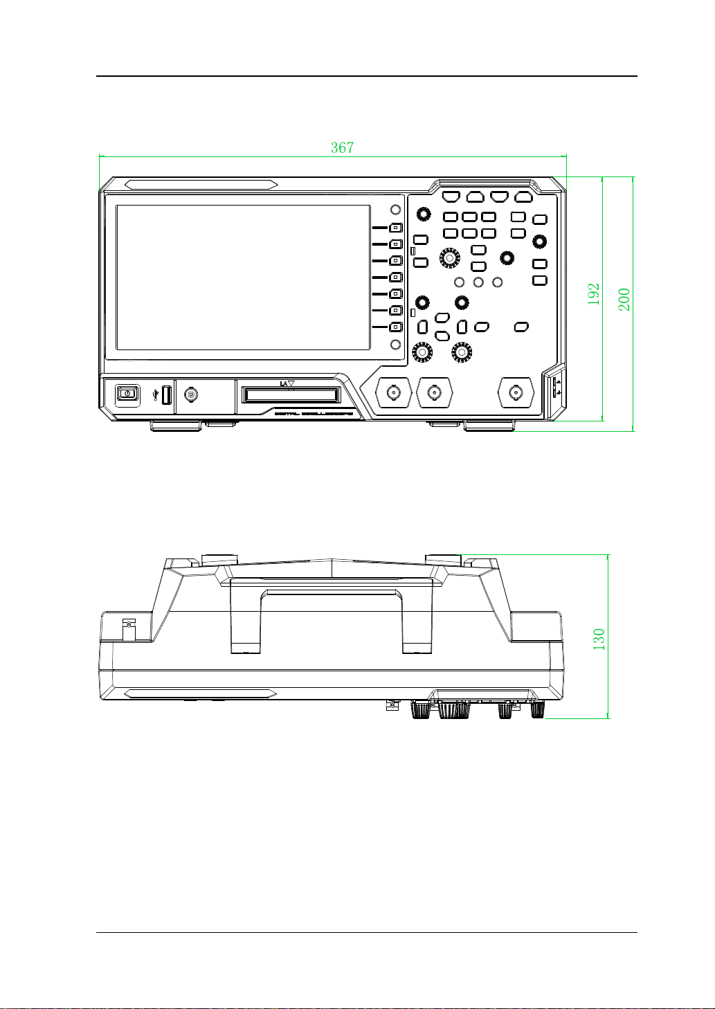
Appearance and Dimensions
Figure 1-1 Front View Unit: mm
Figure 1-2 Vertical View Unit: mm
MSO5000-E User Guide 1-3
RIGOL Chapter 1 Quick Start
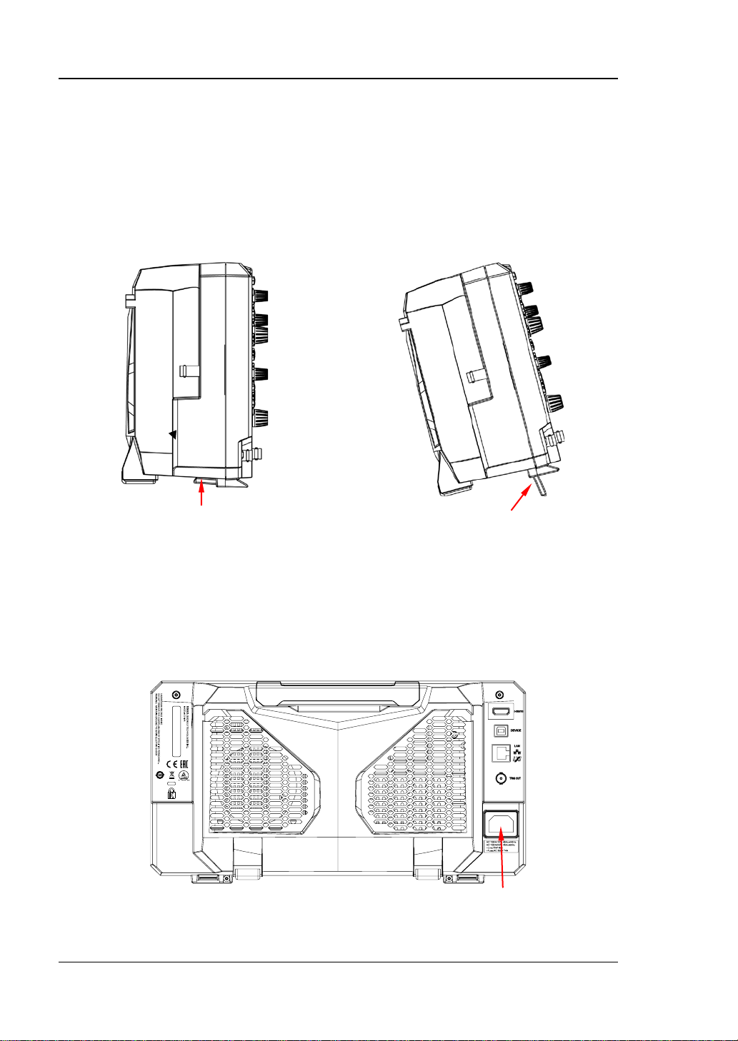
To fold the supporting legs
Power Cord Conn e ct or
To Prepare for Use
To Adjust the Supporting Legs
You can unfold the supporting legs to use them as stands to tilt the instrument
upwards for easier operation and observation, as shown in Figure 1-3. You can also
fold the supporting legs for easier stora ge or shi pme nt when the inst rument is not in
use.
To unfold the supporting legs
Figure 1-3 To Adjust the Supporting Legs
To Connect to AC Power
The input AC power requirements of the oscilloscope are 100~240 V, 45~440 Hz.
Please use the power cord p ro vi de d in th e a c cess ori e s to con ne ct th e os cill osc ope to
the AC power source via the power cord connector, as shown in Figure 1-4.
Figure 1-4 To Connect to AC Power
1-4 MSO5000-E User Guide
Chapter 1 Quick Start RIGOL
CAUTION
To avoid electric shock, ensure that the instrument is correctly grounded.
Turn-on Checkout
When the oscilloscope is connected to power, press the Power key
lower-left corner of the front panel to start the oscilloscope. During the start-up
process, the oscilloscope performs a series of self-tests. After the self-test, the
welcome screen is displayed.
at the
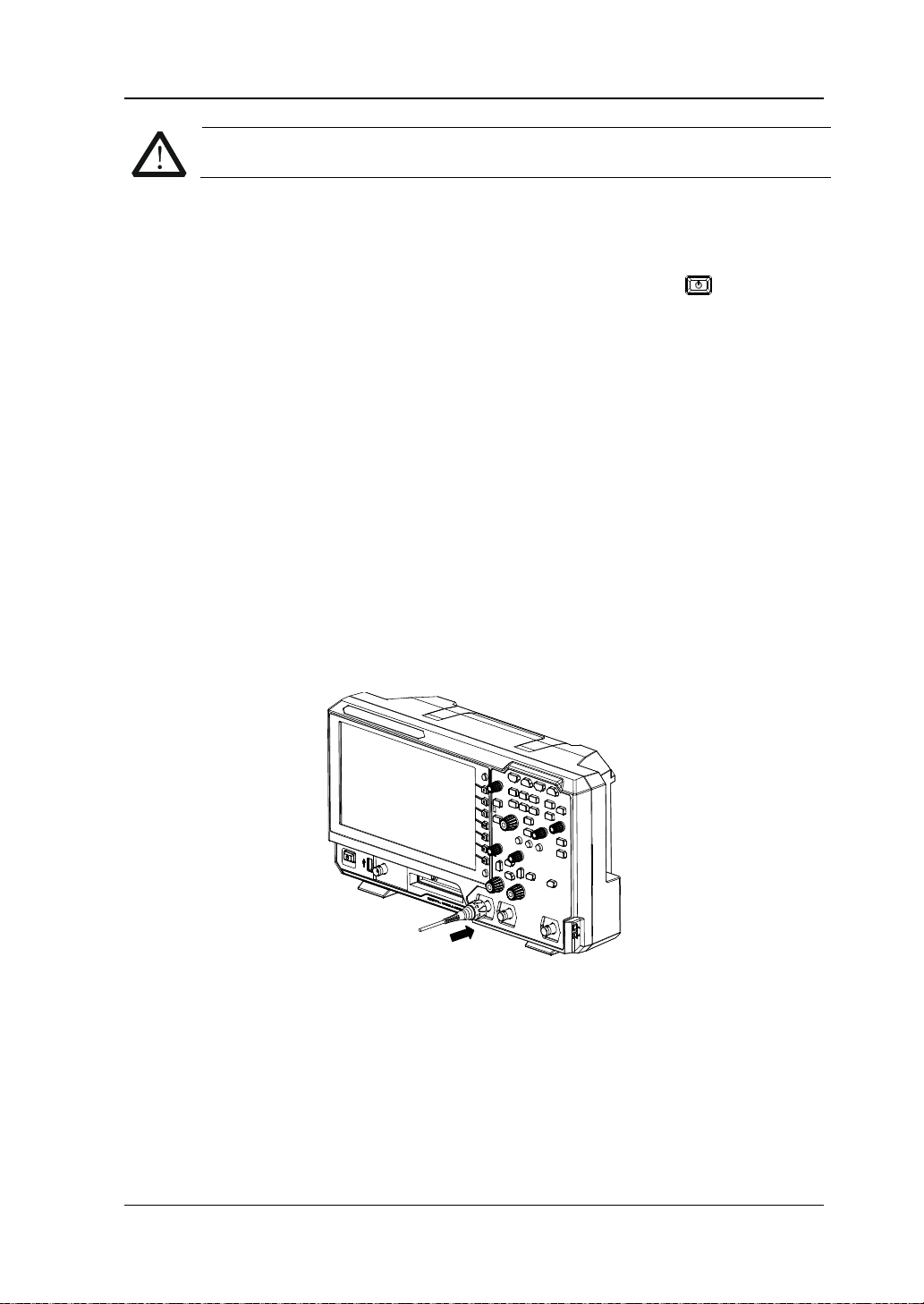
To Connect the Probe
RIGOL provides the passive probe and the logic probe for MSO5000-E series. For
specific probe models, pl ease refer to
technical information of th e pr obes, pleas e refe r to t he s pecified Probe User’s Guide.
Connect the passive probe:
1. Connect the BNC terminal of the probe to an analog channel input terminal of
the oscilloscope on the front panel, as shown in Figure 1-5.
2. Connect the ground alligator clip or spring of the probe to the circuit ground
terminal, and then connect the probe tip to the circuit point to be tested.
MSO5000-E Series Datasheet
. For detai led
Figure 1-5 To Connect the Passive Probe
After you connect the passive probe, check the probe function and probe
compensation adjustment before making measurements. For detailed procedures,
refer to "Function Inspection" and "Probe Compensation".
MSO5000-E User Guide 1-5
RIGOL Chapter 1 Quick Start
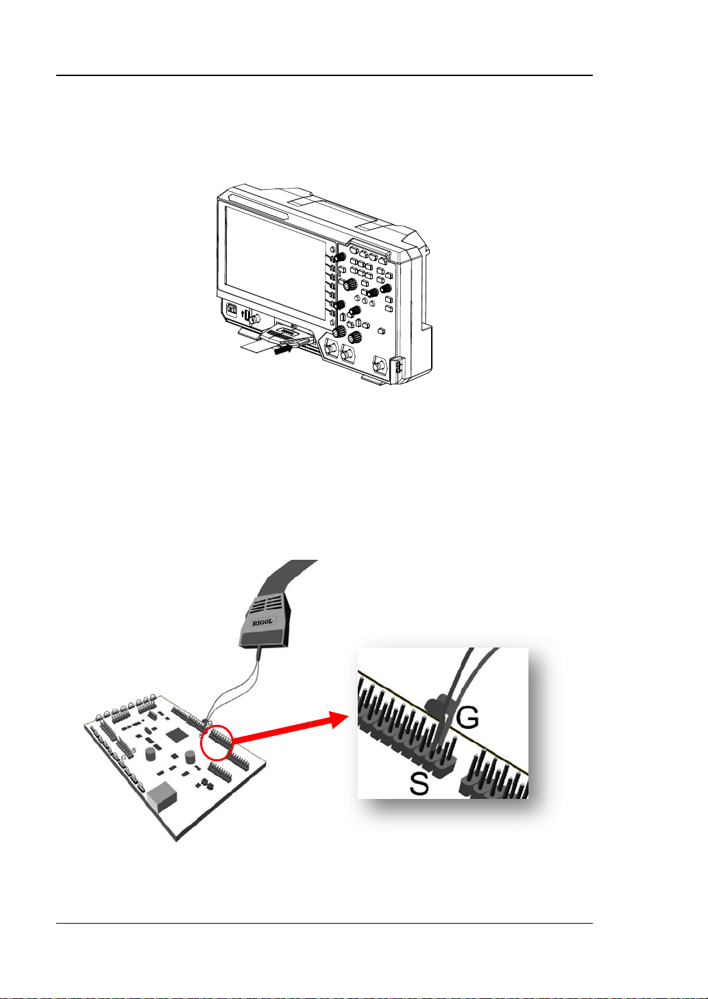
Connect the logic probe:
1. Turn off the power supply of the dev ice under test.
2. Connect the output terminal of the logic probe to the digital channel input
terminal on the front panel of the oscilloscope in the correct direction, as shown
in Figure 1-6.
Figure 1-6 To Connect the Logic Probe
3. Connect the signal lead of each probe at the input terminal of the logical probe to
the test point of the signal under test.
4. Connect the ground lea d of each probe at the i nput terminal of the logical probe
to the ground test point near the signal under test, as shown in Figure 1-7 (a).
Figure 1-7 (b) shows the incorrect connection of the ground lead, which fails to
connect the ground lead to the ground test point near the measured signal.
(a) Correct Connection of the Ground Lead
1-6 MSO5000-E User Guide
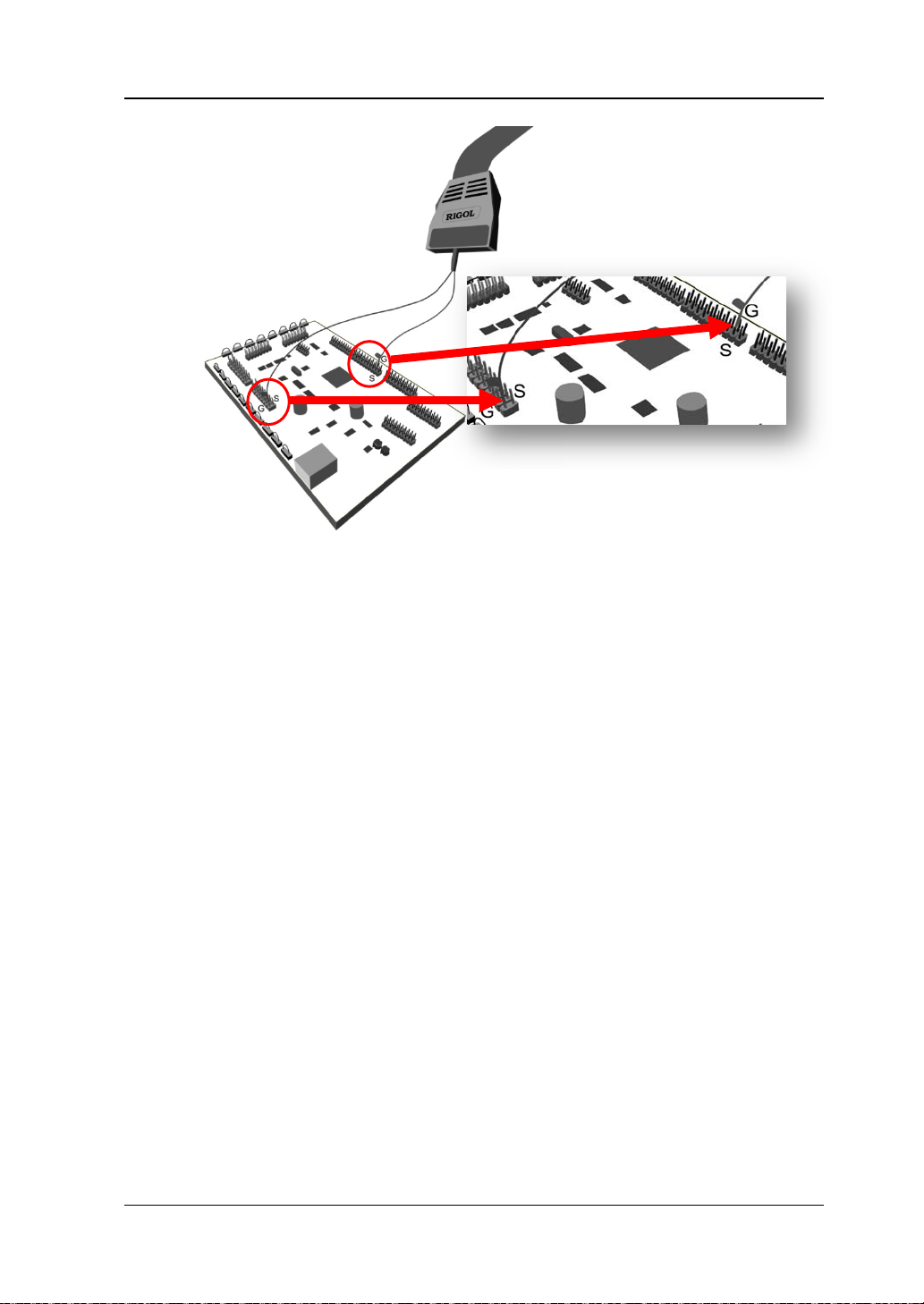
Chapter 1 Quick Start RIGOL
(b) Incorrect Connection of the Ground Lead
Figure 1-7 Ground Lead Connection
5. Repeat the above steps to connect all digital signals.
Note:
The digital channel input terminal does not support hot plugging. Please do not
insert or pull out the logic probe when the instrument is in power-on state.
For grou nd con nection of high-speed signal , the g round le ad shall be c onnected
to the ground test point n ear the measu red si gnal, a nd the gr ound lea d s hall be
kept as s hort as possible.
If the number of input signal channels is more, please connect each signal to a
ground signal as far as possible. If there is only one ground test point, connect
all ground leads on the probe to the ground test point.
According to the actual level range of the measured signal, the threshold value
of the logical probe is set reasonably, and the thresh old value is se t in the middle
of the level range.
MSO5000-E User Guide 1-7
RIGOL Chapter 1 Quick Start
WARNING
To avoid electric shock when using t he probe, please make sure that the
insulated wire of the probe is in good condition. Do not touch the
metallic part of the probe when the probe is connected to high voltage
source.
Compensation Signal Output T ermina l
Ground Terminal
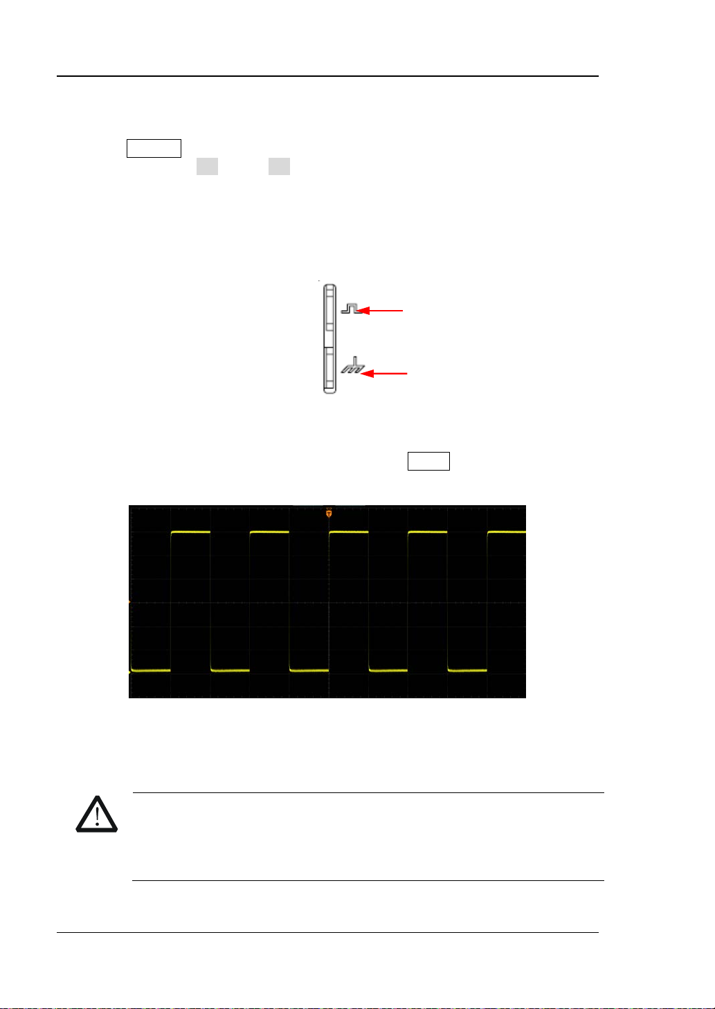
Function Inspection
1. Press Default on the front panel, then a prompt message "Restore default?" is
displayed. Press OK or tap OK to restore the instrument to its factory default
settings.
2. Connect the ground alligator clip of the probe to the "Ground Terminal" as
shown in Figure 1-8 below.
3. Use the probe to connect the input terminal of CH1 of the oscilloscope and the
"Compensation Signal Output Terminal" of the probe, as shown in Figure 1-8.
Figure 1-8 To Use the Compensation Signal
4. Set the probe attenuation to 10X, and then press AUTO.
5. Observe the wavefo rm on the display. In normal condition, the square wavefo rm
as shown in Figure 1-9 should be displayed.
Figure 1-9 Square Waveform Signal
6. Use the same method to test the other channels. If the square waveforms
actually shown do not match that in the figure above, please perform "Probe
Compensation" introduced in the next section.
1-8 MSO5000-E User Guide

Chapter 1 Quick Start RIGOL
Tip
adjustment and cannot be used for calibration.
Over compensated Perfectly compensated Under compensated
The probe compensation signal can only be used for probe compensation
Probe Compensation
When the probes are used for the first time, you should compensate the probes to
make them match the input channels of the oscilloscope. Non-compen s a t e d or
poorly compensated probes may cause measurement inaccuracy or errors. The
probe compensation procedures are as follows:
1. Perform Step 1, 2, 3 and 4 spe cified in "Function Inspection".
2. Check the displayed waveforms and compare them with Figure 1-10.
Figure 1-10 Probe Compensation
3. Use a nonmetallic screwdriver to adjust the low-frequency compensation
adjustment hole on the probe until the waveform is displayed as "Perfectly
compensated" in the figure above.
MSO5000-E User Guide 1-9

RIGOL Chapter 1 Quick Start
No.
Description
No.
Description
1
Capacitive Touch Screen
13
Trigger Control System
2
Function Menu Operation Keys
14
Horizontal Control System
3
Function/Arbitrary Waveform
Generator Setting Key
4
Quick Key (Shortcut Key)
16
Vertical Control System
5
Probe Compensation Signal
Output Terminal/Ground Terminal
6
Common Operation Keys
18
External Trigger Input
7
CLEAR Key
19
Analog Channel Input
8
Auto Waveform Display Key
20
Digital Channel Input
10
Single Trigger Control Key
22
USB HOST Interface
11
Touch Lock Key
23
Power Key
12
Default Setting Key
--
--
1 2 3
4
5 6
7 8
9 10
23 22 21 20 19 18 17
11
12
13
14
15
16
Front Panel Overview
Figure 1-11 Front Panel
Table 1-1 Front Panel Description
Multifunction Knob 17
9 RUN/STOP Key 21
[1]
Note
Note
1-10 MSO5000-E User Guide
: This function is only available for the model installed with the MSO5000-E-AWG option.
[2]
: PLA2216 active logic probe option is required to be ordered.
[1]
15 Navigation Control key
[2]
Function/Arbitrary Waveform
Generator Output Terminal
[1]

Chapter 1 Quick Start RIGOL
7
2
1
Rear Panel Overview
3
4
5
6
Figure 1-12 Rear Panel
1. Handle
Rotate the handle upright to carry the instrument easily. Rotate it
downward if you do not need to carry it.
2. HDMI
Through this interface, you can connect the instrument to an external
display equipped with the HDMI interface (e.g. monitor or projector) to
better observe the wa ve fo rm displa y clearly. At this time, you can also view
the waveforms on the LCD of the instrument.
3. USB DEVICE In te rface
You can connect the instrument to the PC via this interface. Then you can
use the PC software Ultra Scope to send the SCPI commands, the
user-defined programming, or Web Control to control the instrument.
4. LAN Interface
Connect the instrument to network via this interface. The instrument is in
compliance with the stand ards specified in LXI Device Specification 2011. It
can be used to set up a test system.
When you access to the Internet, you can use the Web Control or PC
softwa re Ultra Sc ope to send the SCPI command s or use the user-defined
programming to control the instrument. When update is available, yo u can
perform online upgra ding f or the s ystem s oftw are of the instru ment via th e
LAN interface. After it is connected to the network, you can print the
waveform displayed on the screen when you use the network printer.
MSO5000-E User Guide 1-11

Tip
UPGRADE SERVICE". Tap "Accept" to start online upgrade. Tap "Cancel"
to cancel the online upgrade.
RIGOL Chapter 1 Quick Start
After the oscilloscope is connected to network (if you do not have the access
to the Internet, please ask the administrator to open the specified network
authority), you can perform online upgrading for the system software:
1) Enable the touch screen function. Tap the function navigation ic on
at the lower-left corner of the touch screen to enable the function
navigation.
2) Tap the "Help" icon, and then the "Help" menu is displayed on the
screen.
3) Press Online upgrade or enable the touch screen to tap "Online
upgrade", then a "System Update Information" window is displayed,
requesting you whether to accept or cancel "RIGOL TERMS OF ONLINE
5. Trigger Out and Pass/Fail
TRIG OUT:
The oscilloscope can output a signal that can reflect the current
capture rate of the oscilloscope at each trigger via this interface.
Connect the signal to a waveform display device and measure the
frequency of the signal. The measurement result is the same as the
current capture rate.
Pass/Fail
The instrument can output a pulse from the [TRIG OUT] connector
when a pass/failed event is detected during the pass/fail test.
6. AC Power Cord Connector
Indicates the input terminal where AC power source is connected. The
power supply requirements of the instrument are: 100 V~240 V; 45
Hz~440 Hz. Please use the power cord provided in the accessories to
connect the oscilloscope to the AC power source.
7. Kensington Lock Hole
You can lock the instrument to a f ixed location by using the security lock
(please purchase it by yourself) via the lock hole.
1-12 MSO5000-E User Guide

Chapter 1 Quick Start RIGOL
correspondin g w a vef orm s
B, A×B, A/B, and FFT.
control menu. You can enable or disable any channel or channel group, modify
the 16 digital channels. Besi des, you can also set a label for
counterclockwise to decrease t he offset. During the modification, the waveform
Front Panel Function Overview
Vertical
1, 2: indicates the analog channel switch key. The two channels are marked b y
different colors whi ch are also used to mark b oth the
of the specified channel on the screen and the channel input connectors.
Math: indicates the math operation key. Press this key to enable the math
operation function. The math operations include A+B, ABesides, you can also set the math operation label.
Ref: indicates the reference waveform key. Press this key to open the
reference waveform setting menu. You can compare the actually measured
waveform with the reference waveform to locate the circuit failure.
LA: indicates the logic analyzer key. Press this key to open the logic analyzer
the waveform sizes of the digital channel, modify the threshold of the digital
channel, and group
each digital channel.
Decode: indicates the decode key. Press this key to open the decode setting
menu, and then you can set the decode options. MSO5000-E series supports
the parallel decoding and many protocol decodings. (For details, refer to the
descriptions in "
Vertical
rotate the knob to modify the vertical offset of the current channel waveform.
Each analog channel is conf igured with an independent vertical offset
adjustment knob. Turn it clockwise to increase the offset, and turn it
Protocol Decoding").
OFFSET: indicates the channel vertical offset knob. You can
MSO5000-E User Guide 1-13

RIGOL Chapter 1 Quick Start
would move up and down. Meanwhile, the offset information in the
between "Coarse" and "Fine".
corresponding status label would change accordingly. Press down this knob to
quickly reset the vertical offset to zero .
Vertical
vertical scale of the current channe l. Each analog c hannel is configured with an
independent vertical scale adjustment knob. Turn it clockwise to decrease the
scale, and turn it counterclockwise to increase the scale. During the
modification, the display amplitude of the wa veform will enlarge or reduce. The
scale information in the corresponding status label will change accordingly.
Press down this knob to quickly switch the vertical scale adjustment mode
SCALE: indicates the channel vertical scale knob. Modify the
Horizontal
Zoom: indicates the delayed sweep key. Press this key to enable or disable the
delayed sweep function.
Search: indicates the Search key. Press this key to enter the search setting
menu. The search func t ion allows you to search for relevant events from the
collected data based on the search condition that you set.
Horizontal
rotate the knob to modify the horizontal position (i.g. trigger position). The
trigger point would move left or right relative to the center of the screen when
you rotate the knob. During the modification, waveforms of all the channels
would move left o r ri ght, and the horizontal position message (e.g.
at the upper-right corner of the screen would change accordingly. Press down
this knob to quickly reset the horizontal position (or the delayed sweep
position).
Horizontal
the knob to modify the horizontal timebase. Turn it clockwise to decrease the
timebase, and turn it counterclockwise to increase the timebase. During the
modification, waveforms of all the channels will be displayed in expanded or
POSITION: indicates the horizontal position knob. You can
SCALE: indicates t he horiz ontal timebase knob. You can rotate
)
1-14 MSO5000-E User Guide

Chapter 1 Quick Start RIGOL
Menu: Press this key to open the trigger operation
compressed form, and the timebase message (e.g . ) at the upper section
of the screen would change accor dingly. Press down this knob to quickly switch
the horizontal timebase adjustment mode between "Coarse" and "Fine".
Trigger
menu. This oscilloscope provides various trigger types.
Mode: Press this key to switch the trigger mode to Auto
Normal, or Single.
Force: Press this key to gene rate a trigger signal
forcibly.
Trigger
level. Turn it clockwise to increase the level, and turn it
counterclockwise to decrease the level. During the
modification, the trigger level line would move up and
down and the trigger level/threshold level value at the
upper-right corner of the screen would change
accordingly. Press down the knob to quickly set the
trigger level to 50% of the waveform peak-peak value.
LEVEL: modifies the trigger level/threshold
Function Menu
Measure: Press this key to enter the measurement setting menu. You can set the
measurement source, enable or disable the all measurement function, the statistical
analysis function, and etc. You can make a quick measurement for 41 waveform
parameters.
Acquire: Press this key to enter the acquisition setting menu. You can set the
timebase mode, the acquisition mode, memory depth, and etc.
MSO5000-E User Guide 1-15

RIGOL Chapter 1 Quick Start
Press this key to enable or disable the output of the [Gen Out]
MSO5000-E-AWG option.
Press this key to perform the quick operation, such as screenshot,
Storage: Press this key to enter the file or waveform storage and load interface.
The f ile types for storage include image, waveform, and setups. Besides, waveform
load and setup load are supported. The disk management and file auto naming
function are also supported in this menu.
Cursor: Press this key to enter the cursor measurement menu. The oscilloscope
provides four cursor modes: Manual, Track, XY, and Measure. Note that XY cursor
mode is only available when the horizontal timebase is set to "XY".
Display: Press this key to enter the display setting menu. You can set the display
type, persistence time, wave intensity, and etc.
Utility: Press this key to enter the system function setting menu. You can set
system-related functions or parameters, such as I/O, sound, language, and etc.
Besides, some advanced functions (such as the pass/fail test, waveform recording,
and self-calibration) are also supported.
Navigation Co ntrol Key
With the navigation keys, you can perform re co rding & playing navigation, time
navigation, and event navigation.
Quick Key (Shortcut Key)
waveform saving, setup saving, and etc. Press Utility More
Quick settings to set the quick s ho rtcut keys.
Function/Arbitrary Waveform Generator Setting
connector on the front panel; and then enter the Function/Arbitrary
Waveform Generator setting interface. Enable or disable the status
display of the current signal.
Note: This function is only available for the model installed with the
1-16 MSO5000-E User Guide

Chapter 1 Quick Start RIGOL
Press this key to clear all the waveforms on the screen. If the
being displayed.
Press this key to enable the waveform auto setting function. The
oscilloscope will automatically adjust the vertical scale, horizontal
, and trigger mode accor ding to the in put si gnal to realize
optim al waveform display.
Press this key to set the operating state of the oscilloscope to
r "STOP". In the "RUN" state, the key is illuminated in
yellow. In the "STOP" state, the key is illuminated in red.
Press this key to set the trigger mode to "Single".
Press this key to disable the touch screen function.
ou disable the function, press the key again
to enable it.
Press this key to restore the instrument to its factory default
Clear
oscilloscope is in the "RUN" state, new waveforms will continue
Auto
timebase
RUN/STOP
"RUN" o
Single
Touch Lock Key
Note: By default, the touch screen fun ction of the o scilloscope is
always enabled. If y
Default
settings.
MSO5000-E User Guide 1-17

RIGOL Chapter 1 Quick Start
Multifunction Knob
Non-menu Operation:
In non-menu-operation mode, rotate this knob to adjust the brightness of
waveform display. The settable screen brightness ranges from 1% to 100%.
Turn it clockwise to increase the brightness, and turn it counterclockwise to
decrease the brightness. Press Display Intensity to adjust the waveform
brightness. You can also use the knob to adjust it.
Menu Operation:
In menu-operation mode, for the menu it em that has multi ple para meters unde r
it, when you press the menu softkey, rotate the k no b to select the par ameter
item, then press down the knob to select it (sometimes, the specified parameter
item can be selected by rotating the knob). The knob can al so be used to modif y
parameters, input the filename, etc.
1-18 MSO5000-E User Guide

Chapter 1 Quick Start RIGOL
1 2 3 4 5 6 7 8 9 10 11 12
21 20 19 18 17 16 15 14 13
User Interface
MSO5000-E series has a 9-inch WSVGA (1024×600) LCD, with 256 level gray-scale
display. The user interf ace displa ys the a cqui red w a vef orms, the set ting inf or mati on,
and the measurement results.
Figure 1-13 User Interfac e
1. Digital Chann el Label/Wav eform
The logic high and low level of the digital waveform are displayed in green. Its
edge is displayed in white. The color of the currently selected waveform of the
digital channel is consisten t with that of the channel label, being dis played in red.
The grouping setting fun ction u nder the logi c analyz er function menu can divide
the digital channels into 4 channel groups. The channel label of the same
channel group is displayed in the same color; different channel groups are
marked with different colors.
2. Operating Status
Availabl e states include RUN, STOP, T’D (triggered), WAIT, and AUTO .
MSO5000-E User Guide 1-19

RIGOL Chapter 1 Quick Start
screen waveform
waveform in the memory
3. Horizontal Timebase
Represents the time length per grid in the horizontal axis of the screen.
Use Horizontal
SCALE to modify this paramet er. The adjustable range
of the horizontal timebase is different for different models.
4. Sample Rate/Memory De p th
Displays the current sample rate and memory depth of the analog channel.
The sam ple rate and the memory depth will change along with the horizontal
timebase.
5. Auto Measurement Label
Enable the touch screen, and then tap the label. Up to 41 w av eform parameters
are available for auto measurement. It also offers full-memory hardware
measurement function.
6. Waveform Memory
Provides a diagram of the position of the screen waveform in the memory.
7. Trigger Position
Displays the trigger position of the screen wave form and that of the wavef orm in
the memory.
8. Run/Stop Label
In the run state, the label is displayed in green; while in the stop state, it is
displayed in red . Y o u can e nable the tou ch screen to tap the icon "STOP/RUN" to
control its operating status.
9. Horizontal Position
Use Horizontal
POSITION to modify this par ameter. Press down this knob
to quickly reset the horizontal position.
10. Trigger Type
Displays the currently selected trigger type and trigger condition setting. When
you select diffe rent t rigger t ypes, diff e rent labels a re displa yed . For example,
represents triggering on the rising edge in "Edge" trigger.
11. Trigger Source
Displays the currently selected trigger source (CH1, CH2, EXT, EXT/5, AC Line,
or D0-D15). When you select different trigger sources, different labels are
displayed. For example,
denotes that CH1 is selected as the trigger source.
1-20 MSO5000-E User Guide

Chapter 1 Quick Start RIGOL
12. Trigger LEVEL/Threshold Level
When CH1, CH2, EXT, or E X T /5 is selec t ed a s t he t ri g g er so u r c e, y o u n eed
to set a proper trigger level.
When D0-D15 is s electe d as the tr igger source, yo u need to set a prop er
threshold level.
The trigger level label
is displayed at the left section of the screen, and
the trigger level/threshold lev el value is displayed at t he up per-right corner
of the screen.
When you use Trigger
LEVEL to modify the trigger level/threshold
level, the trigger level/threshold level value will change with the up and
down of
.
Note: In Slope Trigger, Runt Trigger, and Window trigger, you need to set the
upper and lower limits of the trigger level, and two trigger level labels (
and
) are displayed.
13. Operation Menu
Press any softkey on the front panel to activate the corresponding menu.
14. Notification Area
Displays the beeper icon, the USB storage device icon, time, and the LAN
connection icon.
Beeper icon: Pr ess Utility Beeper to turn on or off the beeper. When
the beeper is turned on, will be displayed; when off, will be
displayed.
USB storage device icon: When a USB sto rage device is detected,
will be
displayed.
Time: displays the system time. For the system time setting, refer to
descriptions in "System Ti me".
LAN connection icon: When the LAN interface is successfully connected,
will be displayed.
15. AWG
Displays the on/off status of AWG.
Displays the waveform type set for the current AWG.
It is only av ailable f or the model inst alled with the MSO5000-E-AWG option.
16. Digital Channel Status Area
Displays the current status of the 16 digital channels. The digital channels
currently turned on are displayed in green, and the currently selected digital
channel is highlighted in red. The digital channels turned off are displayed in
gray.
17. Message Box
Displays the prompt messages.
MSO5000-E User Guide 1-21

RIGOL Chapter 1 Quick Start
Tip
and the buttons e nabled. I n this manual , key ope rati on descriptions a re ill ust ra ted
descriptions in relevant chapters.
18. CH2 Status Label
Displays the status of CH2.
Displays the vertical scale of CH2. That is, the volta ge v alue per grid of CH2
in the vertical axis.
Displays the offset of CH2, i.g. the vertical offset of CH2 waveform.
Different labels will be displayed according to the current channel setting.
For example, if you sele ct "DC" f or channel coupling,
enable the bandwidth limit,
19. CH1 Status Label
Displays the status of CH1.
Displays the vertical scale of CH1. That is, the volta ge v alue per grid of CH1
in the vertical axis.
Displays the offset of CH1, i.g. the vertical offset of CH1 waveform.
Different labels will be displayed according to the current channel setting.
For example, if y ou select "DC" f or channel coupling,
enable the bandwidth limit,
20. Analog Channel Label/Waveform
Different channels are marked with different colors. The color of the channel
label is the same as that of the waveform.
21. Function Navigation
Enable the touch screen and then tap this icon to e nable the fun ction navigatio n.
is displayed.
is displayed.
is displayed; if you
is displayed; if you
Touch Screen Controls
MSO5000-E series provides a 9-inch super large capacitive touch screen, which
supports multi-touch and gesture operation. It has strong waveform display
capability and excellent user experience. It features great convenience, high
flexibility, and great sensitivity. The actions supported by the touch screen controls
include tapping, pinching & stretching, dragging, and rectangle drawing.
The touch screen function is available for all the menus displayed on the screen
in details, and as for the touch screen function about some operations, refer to
1-22 MSO5000-E User Guide

Chapter 1 Quick Start RIGOL
Tap
Use one finger to touch the symbol or characters on the screen slightly, as shown in
Figure 1-14. The functions of the tap action include:
Tap the menu displayed on the screen to operate on the menu.
Tap the function navigation i con
to enable the function navigation.
Tap the displayed numeric keypad to set the parameters.
Tap the virtual keypad to set the label name and the filename.
Tap the close button at the upper-right corner of the mes s age box to close the
prompt window.
Tap other windows on the touch screen and operate on the windows.
Figure 1-14 Tap Gesture
at the lower-left corner of the touch screen
Pinch & Stretch
Pinch or stretch two points on the screen with two fingers to zoom in or out the
waveform. To zoom in the wav eform, first pinch the two fingers and then stretch the
fingers; to zoom out the waveform , first stretch the t wo f ingers, and then pinch the
fingers together, as shown in Figure 1-15. The functions of the pinch & stretch action
include:
Pinching & stretching in the horizontal direction can adjust the horizontal
timebase of the waveform.
Pinching & stretchin g in t he v ertical di rection can adjus t the v ertical scale of th e
waveform.
Figure 1-15 Pinch & Stretch Gesture
Drag
Use one f inger to select the object, and then drag the object to a destination place,
as shown in Figure 1-16. The functions of the drag action include:
Drag the waveform to change its position or offset.
Drag the window controls to change the positions of the window (e.g. numeric
MSO5000-E User Guide 1-23

RIGOL Chapter 1 Quick Start
keypad).
Drag the marker to change the position of the marker.
Figure 1-16 Drag Gesture
Rectangle Drawing
Enable the function navigation, and then tap the "Draw rect" icon to switch to the
rectangle dr a w i ng mode. Drag a finger from upper left to lower right across the
screen to draw a recta ngle on the scr e en, as shown in Figure 1-17 (a). Move your
finger away from the screen, and then a menu is displayed on the screen. At this
time, you can tap to select "Trigger zone A", "Trigger zone B", "Histogram",
"Horizontal zoom in", " Vertical zoom in", or "Waveform zoom in". Drag a finger from
lower right to upper left across the screen to draw a rectangle on the screen, as
shown in Figure 1-17 (b). Move your finger away from the screen, and then a menu
is displayed on the screen. At this time, you can tap to select "Trigger zone A",
"Trigger zone B", "Histogram", "Horizontal zoom out", "Vertical zoom out", or
"Wa veform zoom out".
(a) (b)
Figure 1-17 Rectangle Drawing Gesture
Select "Trigger zone A":
Draw the region for Trigger zone A;
Open Trigger zone A;
Open the "Zone Trigger" menu.
Select "Trigger zone B":
Draw the area for Trigger zone B;
Open T rigger zone B;
Open the "Zone Trigger" menu.
Select "Histogram":
Draw the region for the histogram;
1-24 MSO5000-E User Guide

Chapter 1 Quick Start RIGOL
Tip
operation mode is ena bled. By de fault, the wa vef orm oper ation
mode is enabled.
Open the "Histogram" menu.
Select "Horizontal zoom i n": expands the waveforms in the horizontal direction.
Select "Horizontal zoom out": compresses the waveforms in the horizontal
direction.
Select "Vertical zoom in": expands the waveforms in the vertical direction. Select
"Vertical zoom out": compresses the wavef orms in the vertical d irection .
Select "Waveform zoom in": expands the waveforms both in the horizontal and
vertical di rection . Select "Wa veform z oom out": compresses the waveforms both
in the horizontal and vertical direction.
Tap the "Draw rect" icon to switch between the rectangle drawing and waveform
operation modes.
Tap the "Draw rect" icon, if
is displayed, it indicates that the rectangle
drawing mode is enabled. Tap the "Draw rect" icon, if
that the waveform
is displayed, it indicates
MSO5000-E User Guide 1-25

RIGOL Chapter 1 Quick Start
Parameter
Parameter Setting Method
You can use the knob or enable the touch screen to set the parameters of
MSO5000-E series. The common parameter setting methods are as follows:
Method 1:
For the parameters with the sign
panel directly to select the parameter item or modify the parameter value.
Method 2:
For the parameters with the sign
panel and press it down to select the parameter item or modify the parameter value.
Method 3:
For the parameters with
displayed on the menu, rotate the multifunction knob
on the front panel directly to set the parameter, or press down the multifunction
knob
or the specified menu softkey, and then the numeric keypad is shown in
Figure 1-18 below.
, rotate the multifunction knob on the front
, rotate the multifunction knob on the front
Input Field
Delete key
Max. value
Min. value
Default
Clear key
Figure 1-18 Numeric Keypad
In the numeric keypad, rotate the multifunction knob to select the parameter, then
press down the knob to select it. Then input the value or the unit. You can also
enable the touch screen and tap the value or unit in the numeric keypad to input
them. After you input all t he v al ues a nd sele ct the d esired units , the numeric k eypad
is turned off autom atically. This indicates that you ha ve complete d par ameter set ting.
Besides, after you have input the values, yo u can also press OK directly to close the
numeric keypad. At this time, the unit of the parameter is the default unit. In the
numeric keypad, you can also perform the following operations:
Delete the paramet er value that has been input.
Set the parameter to a maximum or minimum value (sometimes, the maximum
or minimum value are the specified one for the current state).
Set the parameter to a default value.
Clear the parameter input field.
1-26 MSO5000-E User Guide

Chapter 1 Quick Start RIGOL
Tip
chapters.
Security Lock Hole
Method 4:
For the parameters without the above signs, press the desired menu softkey to
switch between the parameter items. This method is applicable to the parameters
with only two available options.
The above method is commonly used for the parameter settings of the
oscilloscope. For other methods of parameter settings, refer to details in relevant
To Use the Kensington Security Lock
If necessary, you can lock the ins trument t o a fixed location by using the Kensington
security lock (please purchase it b y yourself), as shown in Figure 1-19. The met hod is
as follows: align the lock with the lock hole and plug it into the lock hole vertically,
turn the key clockwise to lock the oscilloscope and then pull the key out.
Figure 1-19 To Use the Security Lock
Note: Please do not insert other objects into the security lock hole to avoid
damaging the instrument.
MSO5000-E User Guide 1-27

RIGOL Chapter 1 Quick Start
Help Options Help Display Area
To Use the Built-in Help System
The help system of this oscillosc ope provi des ins truc tions f or al l the fun ction k eys on
the front panel and their correspondin g menu keys. The steps fo r opening the built-in
help system are as follows:
1. Press Utility System Help, and then the "Help" menu is displayed
on the screen. You can also use the touch screen function, tap the function
navigation icon
function navigation. Tap the "Help" icon, and then the "Help" menu is displayed
on the screen.
2. Press Content on the front panel or tap the "Content" menu item, and then the
help information is displayed on the screen, as shown in
interface mainly consists of two sections. The left section lists "Help Options",
and the right section is the "Help Display Area".
at the lower-left corner of the touch screen to enable the
Figure 1-20. Th e help
Figure 1-20 Help Information
After opening the help inte rface, you can get its he lp information in the "Hel p Displa y
Area" through the following three methods:
Method 1:
For the keys, you can directly press the front-panel keys (except the Power key
the Menu off key and Back key) to obtain the corresponding help information.
For the buttons, you can rotate the knob or press down the knob to get the
corresponding help information (except the multifunction knob
of rotating the knob is different from that of pressing down the knob, these two
operations will give you different help information.
Method 2:
In the "Help Options", rotate the multifunction knob
1-28 MSO5000-E User Guide
to switch among the help
). As the function
,

Chapter 1 Quick Start RIGOL
Tip
item, then press down the knob to select it (sometimes, the specified
only to follow the above Method 2 or 3 to get the help information.
options to get the corresponding help information.
Method 3:
Enable the touch screen and tap the desired help option to get the corresponding
help information.
Help information for other keys and buttons:
Power key
Menu off key: displays or hides menus. By default, menus are
displayed. If menus are h idden, pressing this key can display the
menus again.
Back key: returns to the p revious menu or the last set function menu.
Multifunction knob : In non-menu-operation mode, rotate this
knob to adjust the brightness of w av eform dis play. In menu-operation
mode, for the menu item that has multiple par a meters un der it, whe n
you press the menu softkey, rotate the knob to select the parameter
parameter item can be selected by rotating the knob).
It can also be used to modify parameters, input a filename, etc.
If the menu item is grayed out, you cannot press the corresponding
front-panel menu key to obtain the help information. What you can do is
: powers on/off the instrument.
To View the Option Information and the Option Installation
MSO5000-E series oscilloscope provides multiple options to fulfill your measurement
requirements. If you need any of these options, order them according to the Order
No. available in "Appendix A: Accessories and Options", and then install the
options according to this section. Besides, you can also view the options currently
installed on the oscilloscope or activate the newly purchased option.
1. View the installed option
The instrument is installed with the trial versions of the options before leaving
factory. When you power on the instrument for the first time, the trial time is
about 2,160 minutes. If your instrument has currently installed the option,
perform the following operations to view the name of the installed option and
other detailed information about the option from the option list.
(1) Press Utility System Help, and then the "Help" menu is displayed
on the screen. You can also use the touch screen function, tap the function
navigation icon
at the lower-lef t corner of the touch screen to enable
MSO5000-E User Guide 1-29

RIGOL Chapter 1 Quick Start
Tip
Sending the SCPI comman ds to install options is supported. F or details, refer
the function navigation. Tap the "Help" icon, and then the "Help" menu is
displayed on the screen.
(2) Press the Option list key or tap the Option list menu item, and then a list
of the options installed is displayed on the screen for users to view.
2. Install the option
The option license is a string of fixed characters. Each instrument has one
unique license. The license f ile should be in specif ic format, with the filename
extension ".lic". After you purchase an option, you will obtain a key (used for
obtaining the license). Then, you can install the option according to the
following steps.
1) Obtain an option license
(1) Log in to the RIGOL official website (www.rigol.com), click License
Activation to enter the "Registered product license code" interface.
(2) In the software license registration interface, input the correct key,
serial number (press Utility System About to obtain the serial
number of the instrument. Y ou can also open the "Help" function menu,
and then press About to obtain the serial number), and the
verification code. Click Generate to obtain the download link of the
option license file. If you need to use the option license file, please
click the link to download the file to the root directory of the USB
storage device.
2) Install the option
(1) Confirm that the option license file is located in the root directory of
the USB storage device, and connect the USB storage device to the
oscilloscope properly.
(2) The Option install key is activated, and press this menu key to start
installing the option.
(3) After installation, a prompt message "Option activated successfully" is
displayed.
Note: After the option has been installe d, you are recommended to restart
the instrument.
Only 1 option license file of one instrument is allowed to be stored in the
same USB storage device, but the USB storage device can store the option
license file of several different instruments. You are not allowed to modify
the licensed filename.
During the installation process, you are not allowed to power off the
instrument or pull out the USB storage device.
to the :SYSTem:OPTion:INSTall command. Installing options b y inputting
the license code manually is not supported.
1-30 MSO5000-E User Guide

Chapter 2 To Set the Vertical System RIGOL
Chapter 2 To Set the Vertical System
MSO5000-E series provides two analog input channels (CH1 and CH2), and each
channel is equipped with an independent vertical control system. The setting
methods for the vertical systems of the two channels are the same. This chapter
takes CH1 as an example t o introduce the set ting method f or the vertical s ystem. For
this oscilloscope, only CH1 is enabled by default.
Contents in this chapter:
To Enable or Disable the Analog Channel
To Adjust the Vertical Scale
Vertical Expansion
To Adjust the Vertical Offset
Channel Coupling
Bandwidth Limit
Probe Ratio
Input Impe da nce
Waveform Invert
Amplitude Unit
Channel Delay
Offset Cal
Channel Label
MSO5000-E User Guide 2-1

RIGOL Chapter 2 To Set the Vertical System
To Enable or Disable the Analog Channel
Enable the an alog channel:
Connect a signal to the channel connector of CH1, and then press 1 in the vertical
control area (Vertical) on the front panel to enable CH1. Then, the backlight of the
channel is illuminated. At this point, the channel setting menu is displayed at the
right section of the screen and the channel is activated. The channel status label at
the bottom of the screen is sh own in t he figure below . You can also enable the touch
screen to tap the channel status label to enable the channel.
The information displa yed in the c hannel status label is related to the current c hannel
setting but irrelevant with the on/off status of the channel. After the channel is
turned on, modify the parameters such as the vertical scale, horizontal timebase,
trigger mode, and trigger level accor ding to the input signal for easy observation an d
measurement of the waveform.
If CH1 is enabled but not activ ated, the cha nnel status label is shown in the follo wing
figure. T o activ ate t he channel, press 1 on the fr ont panel in the vertical control area
(Vertical) or enable the touch screen to tap the waveform activation channel
displayed on the screen.
Disable the analog channel:
If the setting menu of the channel that needs to be disabled (the current channel is
activated) is displayed at the right section of the screen, press the channel key to
disable the channel. If the setting menu of the channel that needs to be disabled is
not displayed at the right section of the screen, f irst open the setting menu of the
channel to be disabled (activate the channel), then press the channel key to disable
the channel. You can also enable the touch sc reen to tap the channel status label to
disable the channel. For example, if CH1 and CH2 are en abled, and C H 2 channel
setting menu is displayed on the screen, then if you need to disable CH1, first
activate CH1, and then press 1 or enable the touch screen to tap the CH1 channel
status label to disable CH1. If CH1 is disabled, the channel status label is shown in
the following figure.
2-2 MSO5000-E User Guide

Chapter 2 To Set the Vertical System RIGOL
Vertical Scale
Value Input Field Decrease Increase
To Adjust the Vertical Scale
Vertical scale indicates the v oltage value per g rid in the vertical a xis of the screen. It
is often expressed in V/div. While you adjust the vertical s cale , the display a mplitude
of the waveform would enlarge or reduce. The scale information of the channel
status label (e.g. as show n in the following figure) at the lower section of the s creen
would change accordingly.
The adjustable range of the vertical scale is related to the currently set probe ratio
and input impedance. By default, the probe ratio is 1X and the input impedance is 1
MΩ. The adjustable range of the vertical scale is from 500 μV/div to 10 V/div.
When CH1 is turned on, you can adjust the vertical scale with the following three
methods:
Rotate Vertical
(clockwise to reduce the scale and counterclockwise to increase).
Enable the touch screen function and adjust the vertical scale with the pinch &
stretch gesture on the touch screen. For details, refer to the "P inch & Stretch"
section.
Enable the touch screen f unction , an d t ap the channel status label at the bot to m
of the screen. The following window is displayed. Tap the
right side of the Scale input field to decrease or increase the scale. You can also
tap the Scale input field to input a specific value with the displayed nume ric
keypad.
SCALE that corresponds to CH1 to adjust the vertical scale
icon at the
In the vertical control area (Vertical) on the front panel, press Vertical
to adjust the ver tical sc ale in "Coarse" (by default)
press 1 More Fine to enable or disable fine adjustment.
Fine adjustment: Rotate Vertical SCALE to further adjust the vertical scale
within a relatively smaller range to improve vertical resolution. If the amplitude
of the input waveform is a little bit greater than the full scale under the current
scale and the amplitude would be a little bit lower if the next scale is used, fine
adjustment can be used to improve t he amplitude of waveform display to view
signal details.
Coarse adjustment (take counterclockwise as an example): Rotate Vertical
SCALE to set the vertical scale at 1-2-5 step, i.e. 500 μV/div, 1 mV/div, 2 mV/div ,
5 mV/div, 10 mV/div…10 V/div.
MSO5000-E User Guide 2-3
SCALE
or "Fin e" mode. You can also

RIGOL Chapter 2 To Set the Vertical System
Vertical Offset
Vertical Expansion
When changing the vertical scale of the analog channel by rotating the Vertical
SCALE
"Center" or "GND" (Ground). By default, "GND" is selected under Expand.
Press 1 More, then press Expand continuously to select "Center" or "GND".
Center: when the vertical scale is changed, the waveform will be expanded or
GND: when the vertical scale is changed, the waveform will be expanded or
knob, you can select to e xpand or compress the wavefor m ar ound the
compressed around the screen center.
compressed around the signal ground level position.
To Adjust the Vertical Offset
Vertical offset indicates the offset of the signal ground level position of th e w a ve form
from the screen center in the vertical direction. Its unit is consistent with the
currently selected amplitude unit (refer to "Amplitude Unit"). When adjusting the
vertical offset, the waveforms of the corresponding channel moves up and down.
The vertical offset information (as shown in the following figure) in the channel
status label at the bottom of the screen will change accordingly.
The adjustable range of the vertical offset is related to the current input impedance,
probe ratio, and vertical scale.
When CH1 is turned on, you can adjust the vertical offset with the following four
methods:
Rotate Vertical
offset within the adjustable range. Rotate this knob clockwise to increase the
vertical offset, and rotate it counterclockwise to reduce the vertical offset.
Pressing down the knob can quickly reset the vertical offset (set the vertical
offset to 0).
Menu setting: Press 1 More Offset, and then the numeric keypad is
displayed. Input the offset v alue with the numeric keypad.
Enable the touch screen, and then adjust the vertical offset with the drag
gesture. For details, refer to the "Drag" section.
Enable the touch screen function, and tap the channe l status la bel at the bottom
of the screen. The following window is displayed. Tap the
right side of the Offset input field to decrease or increase the offset. You can
also tap the Offset input field to input a specific value with the displayed
numeric keypa d .
OFFSET that corresponds to CH1 to adjust the vertical
icon at the
2-4 MSO5000-E User Guide

Chapter 2 To Set the Vertical System RIGOL
Value Input Field Decrease Increase
Channel Coupling
The undesired signals can be filtered out by setting the coupling mode. Fo r example ,
the signal under test is a square waveform with DC offset.
When the coupling mode is "DC": the DC a nd AC comp onents of the si gnal under
test can both pass the channel.
When the coupling mode is "AC": the DC components of the signal under test
are blo cked.
When the coupling mode is "GND", the DC and AC components of the signal
under test are both blocked.
Press 1 to open the setting menu of CH1. Then, press Coupling continuously or
rotate the multifunction knob to select the desired coupling mode (by default, it
is DC). The current coupling mode is displayed in the channel status label at the
bottom of the screen, as shown in the figure below. You can also enable the touch
screen, and then touch the CH1 setting menu to select the desired coupling mode.
DC AC GND
Bandwidth Limit
MSO5000-E se ries supports t he bandwidth li mit fun ction. Setti ng the bandwi dth limit
can reduce the noises in the displayed wa veforms. F or example, the signal under test
is a pulse with high frequency oscillation.
When the bandwidth limit is disabled, the high frequency components of the
signal under test can pass the channel.
When you enable the bandwidth limit and limit it to 20 MHz, the high f requency
components found in the signal under test that are greater than 20 MHz are
attenuated.
Press 1 to open the setting menu of CH1.Then, press BW Limit continuously or
rotate the multifunction knob to select the desired bandwidth limit. Press down
the knob to select it. By default, it is OFF. When the bandwidth limit is enabled, the
MSO5000-E User Guide 2-5

RIGOL Chapter 2 To Set the Vertical System
Attenuation Ratio
(display amplitude of the signal: actual amplitude
of the signal)
0.01X
100X
0.01:1
100:1
character "B" will be displayed in the channe l status label at the bot tom of the screen,
as shown in the figure below. You can also enable the touch screen, and then tap the
CH1 setting menu to select the desired bandwidth limit.
The bandwidth limit that you select is based on the bandwidth of your oscilloscope
model, as shown in Table 2-1.
Table 2-1 Bandwidth Limit
Bandwidth of the Oscilloscope Model Availab le Bandwidth Limit
150 M (MSO5152-E) 20 M
Note: Bandwidth limit can not only reduce the noise, but also can attenuate or
eliminate the high frequency components of the signal.
Probe Ratio
MSO5000-E series allows you to set the probe attenuation manually. To obtain the
correct measu re ment results, you must set the probe ratio pr operly. By default, the
probe ratio is 1X.
Press 1 to open the setting menu of CH1.Then, press Attenuation continuou s ly or
rotate the multifunction knob to select the desired probe ratio. You can also
enable the touch screen, and then touch the CH1 set t ing menu to select the desired
probe ratio. The probe ratio values available are as shown in Table 2-2.
Table 2-2 Probe Ratio
Menu
0.02X
0.05X
0.1X
0.2X
0.5X
1X (default)
2X
5X
10X
20X
50X
2-6 MSO5000-E User Guide
0.02:1
0.05:1
0.1:1
0.2:1
0.5:1
1:1
2:1
5:1
10:1
20:1
50:1

Chapter 2 To Set the Vertical System RIGOL
200X
50000X
200:1
50000:1
(b) "Inv ert" On
500X
1000X
2000X
5000X
10000X
20000X
500:1
1000:1
2000:1
5000:1
10000:1
20000:1
Input Impedance
To reduce the circuit load between the oscillosco pe and the circuit under test, this
oscilloscope provides the default 1 MΩ input impedance. The Impedance menu is
grayed out and you are not allowed to set it manually.
Waveform Invert
Press 1 to open the setting menu of CH1. Then, press Invert continuously to enable
or disable the wavefo rm invert. When enabled, the channel label is displayed, as
shown in the following figure.
When disabled, the waveform is displayed normally; when enabled, the voltage
values of the display ed wa veform a re inverted (as shown in Figure 2-1) . Enabling the
waveform invert will also change the result of math function and waveform
measurement.
(a) "Invert" Off
Figure 2-1 Waveform Invert
Note: When the waveform invert is enabled, the trigger edge or the trigger polarity
will change (e.g. Edge trigger, Pulse trigger, or Slope trigger).
MSO5000-E User Guide 2-7

RIGOL Chapter 2 To Set the Vertical System
Amplitude Unit
Select the amplitude displ ay unit f or the cur rent channel. The available units are W, A,
V, and U. When the unit is changed, the unit related to the relevant functions of the
channel will change accordingly.
Press 1 More Unit, press Unit continuously or rotate the multifunction knob
to select a unit. You can also enable the touch screen to select the desired unit
with touch gestures. The default unit for the value is V.
Channel Delay
When using an oscilloscope for actual measurement, the transmission delay of the
probe cable may bring relatively grea t er errors (zero offset). MSO5000-E allows you
to set a delay time for calibrating the zero offset of the corresponding channel. Zero
offset is defined as the offset of the crossing point o f the w a vef orm and trigger lev e l
line relative to the trigger position, as shown in Figure 2-2.
Figure 2-2 Zero Offset
Press 1 More Ch-Ch Skew, rotate the multifunction knob or use the
numeric keypa d to set the desired delay calibration time. The available range of the
delay calibration time is from -100 ns to 100 ns.
Note: This parameter is related to the instrument model and the current horizontal
timebase setting. The larger the horizontal timebase is, the larger the setting
step will be.
2-8 MSO5000-E User Guide

Chapter 2 To Set the Vertical System RIGOL
Offset Cal
When you use an oscilloscope to make actual measurements, a small offset that
arises from the temperature drift of the component or external environment
disturbance may occur on the zero-c ross volta ge of the channel, whi ch will af fect the
measurement results of the vertical parameters. MSO5000-E allows you to set an
offset calibration voltage for calibrating the zero point of the corresponding channel,
so as to improve the accurac y of the measurement results.
Press 1 More Offse t Cal, rotate the multifunction knob or use the pop-up
numeric keypa d to set the offset calibration value.
Note: If the z er o-cross voltage of the channel has a larger amplitude offset that
exceeds the adjustable null range, please perform self-calibration for the
instrument to ensure the measurement accuracy. For details, refer to
descriptions in "Self-calibration".
Channel Label
The instrument uses the channel number to mark the corresponding channel by
default. For ease of use, you can also set a label for each channel. For example,
".
"
Press 1 More Label to enter the label setting menu. You can use the built-in
label or manually input a label. Three input methods are available for you to input a
label name, including Chinese, English, and Traditional Chinese.
The label setting menu includes the following menu items.
Press Display to turn on or off the display of the channel label. If it is enabled,
the label will be dis pla y e d at the left side of the waveform. When on, CH1 is, by
default, displayed to be the channel label.
Press Library to select the preset labels such as CH1, ACK, ADDR, BIT, CLK, CS,
DATA, IN, MISO, MOSI, OUT, RX and TX.
Press Label and the label editing interface is automatically display ed as shown in
Figure 2-3. Y ou can input the label manually. For the label input method, ref er to
"To Create a Folder".
MSO5000-E User Guide 2-9

RIGOL Chapter 2 To Set the Vertical System
Label Input Area Input Selection Area Virtual Keypad Delete Key
Upper-lower
Case Switch
Figure 2-3 Label Editing Interface
For example, set the label to "
knob
to select "Caps" and press down the knob to switch the uppercase or
". In the virtual keypad, rotate the multifunction
lowercase mode. Rotate the multifunction kno b and select "C", press down the knob.
Then, in the input selection area , r otate the multifun ction kno b and select "C" . Press
down the knob to i nput "C ". Use the same method t o i nput "hn1". After finishing the
input, press OK to finish the editing. Y ou can also enable the t ouch screen to o perate
by touch gestures. If Display is enabled, the label will be displayed at the left
of CH1 wav e form.
T o delete or modi fy t he input cha racters, rotate the mul tifunction knob
or enable
the touch screen to realize it.
Rotate the multifunction knob
: use the delete key to delete or modify the
characters. To modify the characters, input the desired characters again.
Enable the touch screen: use the touch gestures to directly move the cursor to
the right s ide of the character required to be deleted or modified, and then tap
the delete key to delete the character. To modify the characters, input the
desired character again or delete the character.
2-10 MSO5000-E User Guide

Chapter 3 To Set the Horizontal System RIGOL
Chapter 3 To Set the Horizontal System
Contents in this chapter:
To Adjust the Horizontal Timebase
To Adjust the Horizontal Position
Delayed Sweep
MSO5000-E User Guide 3-1

RIGOL Chapter 3 To Set the Horizontal System
Decrease the timebase Increase the timebase
To Adjust the Horizontal Timebase
Horizontal timebase, also called the horizontal scale, refers to the time of each grid in
the horizontal direction of the screen. It is usually expressed in s/div. The adjustable
range of the horizontal timebase is related to the model type.
While you change the horizontal timebase, the displayed waveforms of all channels
are expanded or compressed horizontally relative to the current selected horizontal
reference baseline (refer to "Horizontal Expansion"). The horizontal timebase at
the upper-left corner of the screen will be changed accordingly, as shown in the
figure below.
You can adjust the horizontal timebase with the following three methods:
Rotate Horizontal
available range (clockw ise to red uce the horizontal timebase and
counterclockwise to increase).
Enable the touch screen function and adjust the horizontal timebase with the
pinch & stretch gesture on the touch screen. For details, refer to the "Pinch &
Stretch" section.
Enable the touch screen function, and ta p the horizontal timebase label
at the top of the screen. The following window is displayed. Tap the
icon at the right side of the Scale input field to decrease or increase the
horizontal scale. You can also tap the Scale input field to input a specific value
with the displayed numeric keypad.
SCALE to adjust the horizontal timebase within the
In the Horizontal control area (Horizontal), rotate the Horizontal
to switch the adjustment mode between "Coarse" and "Fine" (by default, it is Coarse).
You can also press Acquire Fine to enable or disable the fine adjustment of the
horizontal timebase.
Coarse adjustment: Rotate the Horizontal SCALE knob will adjust the
horizontal timebase of the waveforms of all channels at 1-2-5 step within the
adjustable range. Rotate it clockwise to reduce the horizontal timebase, and
counterclockwise to increase the horizontal timebase.
Fine adjustment: Rotate the Horizontal SCALE knob will adjust the
horizontal timebase o f the waveforms of all channels with a minor step value
within the adjustable range. Rotate it clockwise to reduce the horizontal
3-2 MSO5000-E User Guide
SCALE knob

Chapter 3 To Set the Horizontal System RIGOL
Decrease the position Increase the position
timebase, and counterclockwise to increase the horizontal timebase.
Note: When the delayed sweep is enabled, rotate the Horizontal
to adjust the timebase for the delayed sweep. The delayed sweep timebase
displayed in the center of the s creen will be change d a ccordi ngly, as shown in
the following figure.
SCALE knob
To Adjust the Horizontal Position
Horizontal position, also called tri gger position, refers to the trigger point position of
the waveforms of all channels i n the horizo ntal direction relative to the screen center.
When the waveform trigger point is at the left (right) side of the screen center, the
horizontal position is a positive (negative) v alue.
While you change the horizontal position, the waveform trigger points and the
displayed wavef orms of all channe ls are move d left and right. The h orizontal posit ion
at the right-upper corner of the screen changes accordingly, as shown in the figure
below.
You can adjust the horizontal position with the following three methods:
Rotate Horizontal
waveforms of all channels. When you rotate it clockwise, the wavefo r m trigger
point moves right on the screen; when you rotate it counterclockwise, the
waveform trigger point moves left on the screen. Pressing down the knob can
quickly reset the horizontal position (reset to 0).
Enable the touch screen function and adjust the horizontal position with the
drag gesture on the touch screen. For details, refer to the "Drag" section.
Enable the touch screen function, and tap the horizontal position label
at the top of the screen. The following window is displayed. Tap the
icon at the right side of the Pos input field to decrease or increase the h orizo ntal
position. You can also tap the Pos input field to input a specific value with the
displayed numeric keypad.
POSITION to adjust the horizontal position of the
MSO5000-E User Guide 3-3

RIGOL Chapter 3 To Set the Horizontal System
Wavef orm Before Enlargement
Horizontal Position of the
Waveform After Enlargement
Note: When the delayed sweep is enabled, rotate the Horizontal POSITION
knob to adjust the horizo nt al position of t he dela y ed swee p (press down the k n ob to
quickly reset it). The horizontal position of the delayed sweep at the upper-right
corner of the screen changes accordingly.
Delayed Sweep
Delayed sweep can be used to enlarge a length of waveform horizontally to view
waveform details.
In the horizontal control area on the front panel, press Zoom to enable or disable
the delayed sweep. By default, it is disabled. Y ou c an also press Acquire More
Zoom to enable or disable the delayed sweep function.
Note: To enable the delayed sweep, you must ensure that the current timebase
mode is "YT".
In delayed sweep mode, the screen is divided into two display areas as shown in
Figure 3-1.
Main
Timebase
Timebase
of the
Delayed
Sweep
Delayed Sweep
3-4 MSO5000-E User Guide
Figure 3-1 Delayed Sweep Mode

Chapter 3 To Set the Horizontal System RIGOL
Waveform before enlargement:
The waveform in the area that is not covered by subtransparent blue in the upper
part of the screen i s t he waveform bef ore enla rgeme nt. Its horiz ontal timebase (also
called main timebase) is displayed at the upper-left corner of the screen. You can
rotate the Horizontal
the Horizontal
SCALE knob to enlarge or reduce this area.
POSITION knob to move t he area left and right or rotate
Note: If you need to modify the horizontal timebase (also called main timebase) of
the normal sweep, please disable the delayed sweep function first. Rotate the
Horizontal
SCALE knob to set the required main timebase, and then
enable the delayed sweep function.
Waveform after enlargement:
The waveform in the lower part of the screen is the horizontally expanded delayed
sweep waveform. Its horizontal timebase (also called the timebase of the delayed
sweep) is displayed on the screen. Compared with the main timebase, the timebased
of the delayed sweep has increased the w aveform resolution, as shown in Figure 3-1.
At this time, you can rotat e t he Horizontal SCALE knob to adjust the timebase
of the delayed sweep, and rotate the Horizontal
POSITION knob to adjust the
horizontal position of the delayed sweep.
Note: The timebase of the d elayed sweep should be smaller than or equal to the
main timebase.
MSO5000-E User Guide 3-5


Chapter 4 To Set the Sample System RIGOL
Chapter 4 To Set the Sample System
Contents in this chapter:
Timebase Mode
Acquisition Mode
Sampling Mode
Sample Rate
LA Sample Rate
Memory Depth
LA Memory De pth
Anti-Aliasing
Horizontal Expansion
MSO5000-E User Guide 4-1

RIGOL Chapter 4 To Set the Sample System
II I
III IV
A
B
C
D
Signal must be
centered horizontally
Timebase Mode
MSO5000-E series supports three available timebase modes: YT mode, XY mode,
and ROLL mode. By default, the timebase mode is YT.
Press Acquire Timebase Mode on the front panel, and then rotate the
multifunction knob to select the desired timebase mode . Then, press down the
knob to select the mode. Y ou can also press Timebase Mode continu ously to select
the mode or enable the touch screen to tap the desired mode and select it.
YT Mode
In this mode, the Y axis represents voltage, and the X axis represents time.
Note: Only when this mode is enabled, can delayed sweep be turned on. In this
mode, when the horizontal timebase is equal to or greater than 200 ms/div,
the instrument enters slow sweep mode. For details, refer to descriptions in
"ROLL Mode".
XY Mode
In this mode, both the X axis and the Y axis represent the voltage. The mode
changes the display from voltage-time display mode to voltage-v oltage display. You
can use the Lissajous method to measure the phase deviation of the two input
signals whose frequencies are the same. The following figure shows the
measurement schematic diagram of phase deviation.
Figure 4-1 Measurement Schematic Diagram of Phase Deviation
4-2 MSO5000-E User Guide

Chapter 4 To Set the Sample System RIGOL
According to sinθ=A/B or C/D, θ is the phase deviation angle between the two
channels. The definitions of A, B, C, and D are shown in the a bove figure. The phase
deviation angle is obtained, that is:
θ=±arcsin(A/B) or ±arcsin(C/D)
If the principal axis of the ellipse is within Quadrant I and III, the phase deviation
angle obtained should be within Quadrant I and IV, namely within (0 to π/2) or (3π/2
to 2π). If the principal axis of the ellipse is within Quadrant II and IV, the phase
deviation angle obtained should be within Quadrant II and III, namely within (π/2 to
π) or (π to 3π/2).
The XY function can be used to measure the phase deviation occurred when the
signal under test passes through a circuit network. Connect the oscilloscope to the
circuit to monitor the input and output signals of the circuit.
Application example: measures the phase deviation between the input signals of
two channels.
Use Lissajous method
1. Connect one sine signal to CH1, and then connect another sine signal (with the
same frequency and amplitude as the previous one but a 90° phase deviation
from the previous one) to CH2.
2. Press AUTO, after you select "XY" mode, rotate the Horizontal
SCALE to
adjust the sample rate properly to obtain a better view of Lissajous graph for
observation and measurement.
3. Rotate the Vertical SCALE knob t hat corresponds to CH1 and CH2
respectively to make the signals easy to observe. Then, a circle, as shown in the
figure below, should be displayed.
4. Observe the measurement result shown in the figure above. According to the
measurement schematic diagram of the phase deviation (as shown in Figure
), A/B(C/D)=1. Thus, the phase deviation angle of the two channel input
4-1
signals is
MSO5000-E User Guide 4-3
θ=±arcsin1=90°.

RIGOL Chapter 4 To Set the Sample System
Slow Sweep
200 ms/div or smaller, the instrument enters the "slow sweep" mode in which the
Coupling" to "DC".
Note:
In XY mode, CH1 and CH2 are forced to be enabled. The maximum sample rate
in XY mode is 2 GSa/s. Generally, a longer sample waveform can ensure better
display effect of Lissajous figure. But due to the limitation of the memory depth,
you have to reduce the waveform sample rate to acquire a longer waveform
(refer to the introduction in "Memory Depth"). Therefore, during the
measurement, reducing the sample rate properly can achieve better display
effect of Lissajous figure.
The following functions are disabled in XY mode:
"Delayed Sweep", "To Select the Display Type", "Scale", "Protocol
Decoding", "Pass/Fail Test", "Waveform Recording & Playing", and
"Digital Channel".
ROLL Mode
In this mode, the waveform scrolls from right to left to update the display. The
available range of the horizontal scale is from 200 ms to 1 ks. Press More Auto
ROLL to select "ON". The system automatically enters the ROLL mode, and there is
no slow sweep.
Note:
If the current delay ed swe ep is enable d, the n when y ou ena ble the ROLL mode,
the delayed sweep is disabled a utomatically. When you re-enable the "YT" mode,
the delayed sweep will be re-enabled.
The following functions cannot be set in ROLL mode:
"To Adjust the Horizontal Position" (available when the oscilloscope is in
"Stop" operating status), "Delayed Sweep", "To Trigger the Oscilloscope",
"Protocol Decoding", "Pass/Fail Te st", "Waveform Recording &
Playing", and "To Set the Persistence Time".
It is similar to the ROL L mode. In YT mode, when the horizontal timebase is set to
instrument first acquires the data at the left of the trigger point and then wait s for
a trigger event. After the trigger occurs, the instrument continues to finish the
waveform at the right of the trigger point. When observing the low-frequency
signal in the slow sweep mode, it is recommended that you set "
4-4 MSO5000-E User Guide
Channel

Chapter 4 To Set the Sample System RIGOL
Acquisition Mode
The acquisition mode is used to control how to generate waveform points from the
sample points.
MSO5000-E supports the following four acquisition modes: Normal, Average, Peak,
and High Resolution. By default, the acquisition mode is Normal.
Press Acquire Acquisition on the front pane l, a nd then rotate the multif unction
knob to select the desired acquisition mode. Then, press down the knob to
select the mode. You can also press Acquisition continuously to select the mode o r
enable the touch screen to tap the desired mode and select it.
Normal
In this mode, the oscillosc ope sam ples the signal at a specified fixed time interval to
rebuild the wavefor m. For most of th e wavefor ms, using this mode can produce the
optimal display effects.
Average
In this mode, the oscilloscope averages the waveforms from multiple samples to
reduce the random noise of the input signal and improve the vertical resolution.
Greater number of av era ges can lower the noise an d in crease the vertical resoluti on;
while at the same time, it will slow the response of the displayed waveform to the
waveform changes.
When you select "Average" mode, press Averages and rotate the multifunction
knob
also use the pop-up numeric keypad to input the average count. When the average
count value is in power-of-2 increments, a prompt message "Trim average count" is
displayed. At this time , a value that is s maller t han t he one y ou input an d t he closest
to power-of-2 increments will be input aut omatically. For example, if you input 9 with
the numeric keypad, the average count will be input 8 automatically.
The number of aver ages can be set to 2, 4, 8, 16, 32, 64 , 128 , 256, 512, 1024, 2048 ,
4096, 8192, 16384, 32768, or 65536. By default, it is 2.
or use the numeric keypad to set the desired number of averages. You can
MSO5000-E User Guide 4-5

RIGOL Chapter 4 To Set the Sample System
Figure 4-2 Waveforms before Averaging
Figure 4-3 Waveforms after 128 Times of Averaging
Peak
In this mode, the oscilloscope acquires the maximum and minimum values of the
signal within the sample in terval to get the envel ope of the signal or the narrow pulse
that might be lost. In this mode, signal aliasing can be prevented, but the noise
displayed would be larger.
In this mode, the oscilloscope can display all the pulses whose pulse widths are at
least the same as the sample period.
High Resolution
This mode uses an over-sample technique to average the neighboring points of the
sample waveform. This reduces the random noise on the input signal, generates a
much smoother wavef orm on the s creen an d improv es the v ertical resolution . This is
generally used when the sample rate of the digital converter is greater than the
4-6 MSO5000-E User Guide
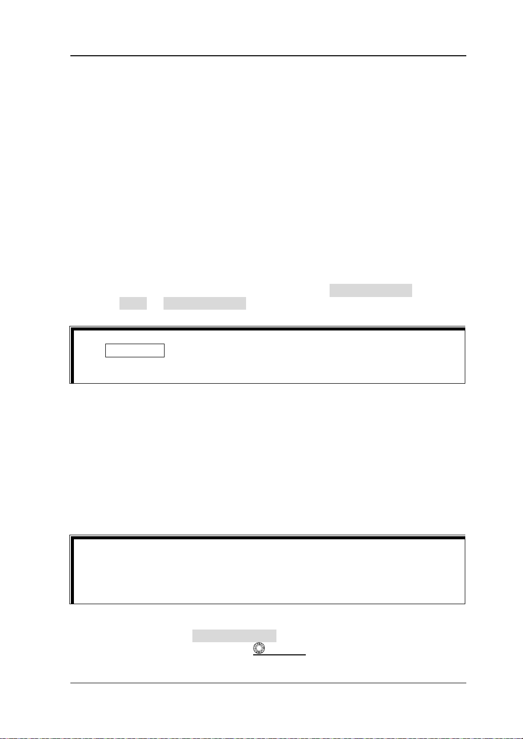
Chapter 4 To Set the Sample System RIGOL
Tip
will maintain its last captured graph. You can still expand or zoom the waveforms
by using the horizontal and vertical control knobs.
Tip
this time.
storage rate of the acquisition memory.
Note:
The "Average" and "High Res" modes use different averaging methods. The
former uses "Multi-sample Average" and the latter uses "Single-sample
Average".
In "High Res" mode, the si gnal ba ndwidt h doe s not e xceed 1 /32 of the sa mplin g
rate.
In "Hig h Res" mode, the highest waveform refresh rate mode is not supported.
Sampling Mode
This oscilloscope only supports the real-time sampling mode. In this mode, the
oscilloscope produce the wav eform display from sa mples collected during one trigger
event. The highest real-time sample rate on the ana log channel of MSO5000-E series
is 4 GSa/s. The current sample rate is displayed under CH SampleRate, and you
can pre ss More CH SampleRate to view it.
Press RUN/STOP on the front panel to stop sampling, and then the oscilloscope
Sample Rate
Sampling is the process of converting the analog signal into the digital signal at a
specif ied time interval and then restoring them in sequence. The sample rate is the
reciprocal of the time interval.
The sample rate of the analog channel is related to the current channel mode. The
maximum real-time sample rate in the single-channel mode of the oscilloscope is 4
GSa/s. The maximum real-time sample rate in the all-channel mode is 2 GSa/s.
Single-channel mode: only one of the channels (CH1 or CH2) is enabled.
All-channel mode: CH1 and CH2 are bot h e nabled.
Note that the currently enabled channel should be used as the trigger source at
Note: The sample rate is displayed both in the status bar at the upper part of the
screen and in the CH SampleRate menu. To indirectly modify the sample
rate, rotate the Horizontal
SCALE knob to adjust the horizontal
MSO5000-E User Guide 4-7
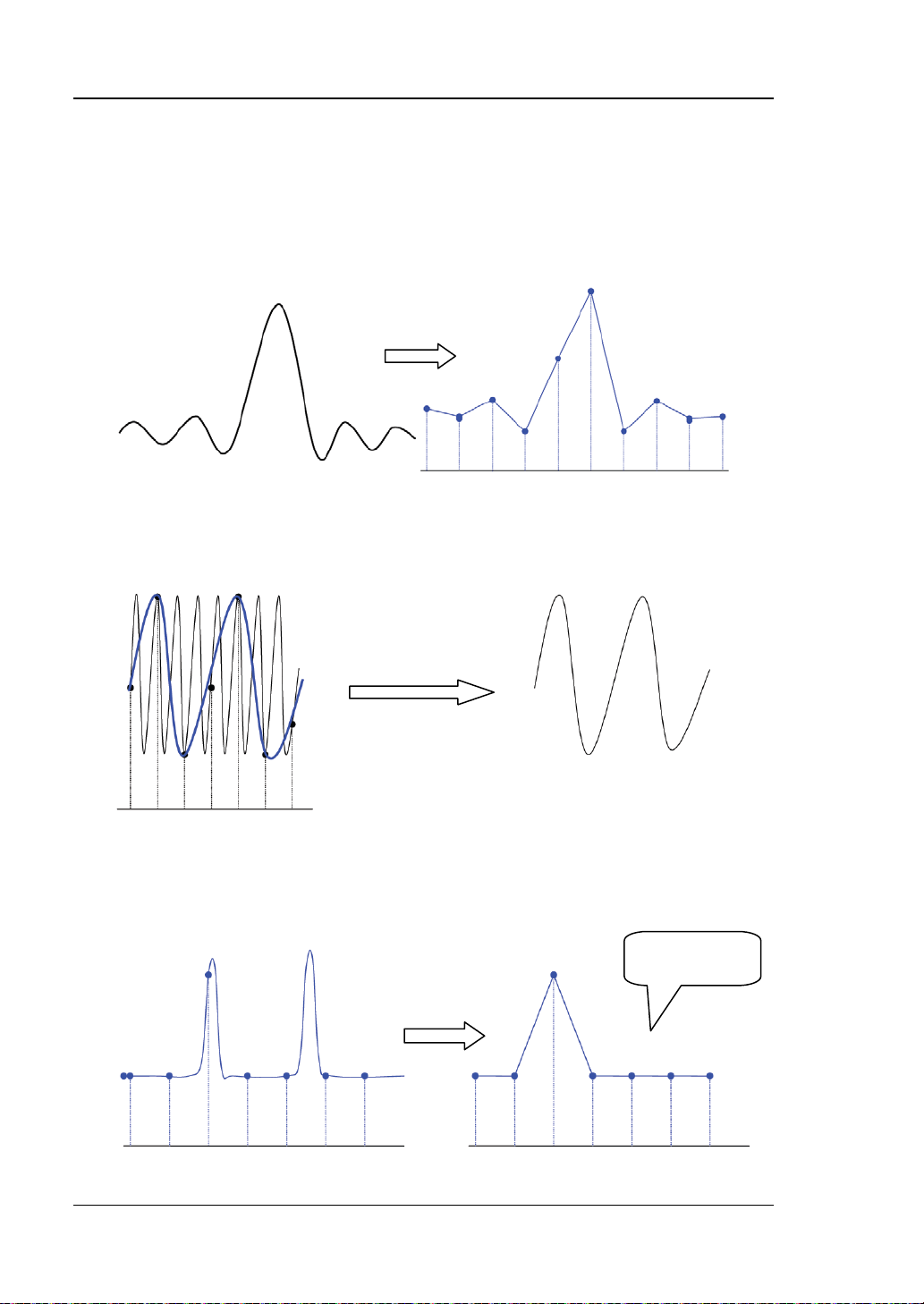
RIGOL Chapter 4 To Set the Sample System
Pulse
disappeared
timebase or modify the m e m ory depth.
The impact of low sample rate on the waveform:
1. Waveform Distortion: when the sample rate is too low, some waveform
details are lost, and the sample waveform displayed is rather different from the
actual waveform of the signal.
2. Waveform Aliasing: when the sample rate is twice lower than the actual
signal frequency (Nyquist Frequency), the frequency of the waveform rebuilt from
the sample data is smaller than the actual signal frequency.
3. Waveform Leakage: when the sample rate is too low, the waveform rebuilt
from the sample data does not reflect all the actual signal information.
4-8 MSO5000-E User Guide

Chapter 4 To Set the Sample System RIGOL
T
Trigger Point
Pre-sample Delayed Sample
Memory Depth
MDepth SRate TScale HDivs=××
MDepth
LA Sample Rate
LA sampling is the process of sampling on the compared digital signals at a certain
time interval. LA sample rate is the reciprocal of the ti me interval. F or example, if the
LA sample rate is 500 MSa/s, it indicates that the oscilloscope will make data
acquisition on the digital si gnals at an interv al of 2 ns . The maximum LA sample rate
of the oscilloscope is 1 GSa/s, an d its display value is related to the sample rate of the
current analog channel.
Note:
The digital signals here mentioned refers to the signal obtained from the
comparison between the input signal and the user-defined threshold level. The
rule of the comparison is that when the amplitude of the input signal is greater
than the threshold level, it is judged to be the logic high level; when the
amplitude of the input signal is smaller than the threshold level, it is judged to
be the logic low level.
LA sample rate is displayed under the LA SampleRate menu. To indirectly
modify the LA sample rate, rotate the Horizontal
the horizontal timebase or modify the memory depth.
SCALE knob to adjust
Memory Depth
Memory depth refers to the numbe r of points of the oscilloscope that can store in one
trigger acquisition. It reflects the storage capability of the acquisition storage. This
oscilloscope is equipped with memory depth of up to 100 Mpts (option).
Figure 4-4 Memory Depth
The following equation shows the relations among memory depth, sample rate, and
horizontal timebase scale:
——indicates the memory depth. The unit is pts.
MSO5000-E User Guide 4-9

RIGOL Chapter 4 To Set the Sample System
SRate
TScale
HDivs
——indicates the sample rate. The unit is Sa/s.
——indicates the horizontal timebase scale. The unit is s/div.
——indicates the number of grids in the horizontal direction. The unit is div.
Therefore, under the same horizontal timebase scale, a h igher memory depth c an
ensure a higher sample rate.
Press Acquire Mem Depth, then rotate the multif unction knob to switch to
the desired memory depth, and then press down the knob to select the option. You
can also press the Mem Depth key continuously or enable the touch screen to
select the memory depth. By default, the memory depth is Auto. The memory depth
of the analog channel is related to the current channel mode.
In single-channel mode, the memory depths available include Auto, 1 Kpts, 10
Kpts, 100 Kpt s , 1 Mpt s, 10 Mpts, 25 M pt s , 50 Mpts, and 100 Mpts.
In all-channel mode, the memory depths av ailable include Auto, 1 Kpts, 10 Kp ts,
100 Kpts, 1 Mpts, 10 Mpts, 25 Mpts and 50 Mpts.
Note: In "Auto" mode, the oscilloscope selects the memory depth automatically
according to the current sample rate.
LA Memory Depth
Press Acquire More to view the memory depth of the current digital channel
under LA Mem Depth. The LA memory depth will change with the memory depth of
the analog channel, and cannot be set separ ately. The maximum LA memory depth is
25 Mpts.
Anti-Aliasing
At a slower sweep speed, the sample rate is reduced, and a dedicated display
algorithm can be used to minimize the possibility of aliasing.
Press Acquire Anti-aliasing to enable or disable the anti-aliasing function. By
default, anti-aliasing is disabled. In this case, it is more likely to generate waveform
aliasing.
Note: This function should be enabled when the horizontal timebase has a large
deviation from the period of the signal under test (e.g. when the horizontal
timebase is greater than five-fold the period of the signal under test).
4-10 MSO5000-E User Guide

Chapter 4 To Set the Sample System RIGOL
Horizontal Expansion
Horizontal expansion indicates the reference position that the screen waveform is
referenced to when it is horizontally expanded or compressed in adjusting the
Horizontal SCALE knob. In YT mo de , p res s Acquire More Expand and
then rotate the multifun ction knob to select the desired reference position. Press
down the knob to select it. You can also press Expand continuously to select it or
enable the touch screen to tap the desired reference. The horizontal expansion
reference supported b y the oscilloscope inclu des Center, Left, Right , Trigger, a nd Use r.
The default is "Center".
Center: when the horizontal timebase is modified, the waveform will be
expanded or compressed horizontally relative to the screen cente r.
Left: when the horizontal timebase is modified, the waveform will be expanded
or compressed horizontally relative to the leftmos t position of the screen.
Right: when the h orizontal timebase is modified, the waveform will be expanded
or compressed horizontally relative to the rightmost position of the screen.
Trigger: when the horizontal timebase is modified, the waveform will be
expanded or compressed horizontally relative to the trigge r point.
User: when the horizontal timebase is modified, the waveform displayed will be
expanded or compressed horizontally relative to the user-defined reference
position.
After you select "User", press Expand User and then rotate the multifunction
knob
rightmost position of the s creen to the leftmost position of the s creen. By default,
it is the screen center. Pressing down the multifunction knob
reset the user-defined reference position to 0.
Note: This function is unav ailable in YT mo de with the delay ed sweep bein g enable d,
XY mode, and ROLL mode.
to set the expansion reference. Its available range is from the
can quickly
MSO5000-E User Guide 4-11


Chapter 5 To Trigger the Oscilloscope RIGOL
Chapter 5 To Trigger the Oscilloscope
As for trigger, you set certain trigger condition according to the requirement and
when a waveform in the waveform stream meets this condition, the oscilloscope
captures this waveform as well as the neighboring part, and displays them on the
screen. For the digital oscilloscope, it samples waveform continuously no matter
whether it is stably triggered, but only stable trigger can be stably displayed. The
trigger module ensures that every timebase sweep or acquisition starts from the
user-defined trigger condition, namely every sweep is synchronous with the
acquisition and the waveforms acquired is overlapped so as to display the stable
waveforms.
Trigger settings should be based on the features of the input signal. To quickly
captu re the desired waveform, you need to understand the signal under test. This
oscilloscope provides abundant trigger types that help you focus on the desired
waveform details.
Contents in this chapter:
Trigger Source
Trigger LEVEL/Threshold Level
Trigger Mode
Trigger Coupling
Trigger Holdoff
Noise Rejection
Trigger Type
Zone Trigger
Trigger Output Connector
MSO5000-E User Guide 5-1

RIGOL Chapter 5 To Trigger the Oscilloscope
Trigger Source
In the trigger control area (Trigger) on the front panel, press Menu Source to
select the desired source, or rotate the multi-function knob to select a desired
source, then press down the knob to select it. You can also press Source
continuously to select the trigger source or enable the touch screen to tap the
desired trigger source and select it.
Analog channels (CH1-CH2), digital channels (D0-D15), EXT, EXT/5, or AC Line can
all be selected as the trigger source.
Analog channel input:
Signals input from analog channels CH1-CH2 can all be used as trigger sources. No
matter whether the channel selected is enabled, the channel can work normally.
Digital ch an n e l in p ut:
Signals input from digital channels D0-D15 can all be used as trigger sources. No
matter whether the channel selected is enabled, the channel can work normally.
External trigger input:
The external trigger source can be used to trigger on the third channel while all the
other two channels are acquiring data. The trigger signal (e.g. external clock or
signal of the circuit under test) will be connected to EXT or EXT/5 trigger source via
the external trigger input terminal [EXT] connector. You can set the trigger
conditions within the rang e of the trigger le vel (fr om -1 V to +1 V for EXT o r from -5
V to +5 V for EXT/5).
AC line input:
The trigger signal is obtained f rom the AC power in put o f the oscilloscope. AC t rigger
is usually used to measure signals relev ant t o the AC power fre quency. For example,
stably triggering the waveform output from the transformer of a transformer
substation. It is mainly used in related measurements of the power industry.
5-2 MSO5000-E User Guide

Chapter 5 To Trigger the Oscilloscope RIGOL
Trigger LEVEL/Threshold Level
The adjustment of the tri gger level/thresh old level is relat ed to the ty pe of the trigge r
source.
When the trigger source is selected from CH1 an d CH2 , rotate the Trigger
LEVEL
line (the color of the trigger level line should be consistent with that of the
channel color) and a trigger label "
move up and down with the variation of the trigger level. When you stopping
modifying the trigger level, the trigger level line disappears in about 2 s. The
current trigger level value is displayed at the upper-right corner of the screen.
Note: In Runt Trigger, Slope Trigger, and Window trigger, you need to set the
upper and lower limits of the trigger level. You can modify the level by rotating
the Trigger
and lower limit of the trigger level is displayed at the upper-right side o f the
screen. Two trigger level labels (
screen. Meanwhile, the real-time trigger level information is displayed at the
lower-left side of the screen, as shown in the figure below. H indicates the upper
limit of the trigger level, L indicates the lower limit of the trigger level, and △
indicates the deviation of the trigger level.
k nob to adjust the trigger level. During the adjustment, a trigger level
" are displayed on the screen, and they
LEVEL knob. The difference between the current upper limit
and ) are displayed at the left s ide of the
When the trigger source is EXT, rotate the Trigger
the trigger level. The current trigger level value is displayed at the upper-right
corner of the screen.
Note: For this trigger source, only the variation of the trigger level value is
displayed on the screen during the adjustment of the trigger level, without
displaying the trigger level lines on the screen.
When the trigger source is AC Line, there is no trigger level.
When the trigger source is selected from D0 to D15, rotate the Trigger
LEVEL
displayed at the up per-rig ht corne r of th e scre en. In addition, you can also press
LA to enter the LA logic analysis setting menu. Then set the threshold level of
the digital channel in the sub-menu thr eshold setting. For the setting method,
refer to "
You can also enable the touch screen function to adjust the trigger
level/threshold level. Two methods are available for you:
MSO5000-E User Guide 5-3
k nob to adjust the threshold level. The current threshold level value is
To Set the Threshold".
LEVEL k nob to ad jus t

RIGOL Chapter 5 To Trigger the Oscilloscope
Pre-trigger Buffer
Post-trigger Buffer
Trigger Event
Acquisition Memory
Level Input Field Decrease the level Increase the level
Method 1: Enable the touch screen and drag the trigger level line to adjust the
trigger level. For details about the operations, refer to descriptions in "Drag"
section.
Method 2: Enable the touch screen function, and tap the trigger setting label
at the upper-right corner of the screen. The following window is
displayed. Tap the icon at the right side of the Level input field to
decrease or increase the trigger level. You can also tap the Level input f ield to
input a specific value with the displayed numeric keypad.
Trigger Mode
The following is the schematic diagram of the acquisition memory. To easily
understand the trigger eve nt, we classify t he acquisition memory into the pre-trigger
buffer an d pos t-trigger buffer.
Figure 5-1 Schematic Diagram of the Acquisition Memory
After the system runs, t he oscilloscope operates b y first filling the pre-trigger buffer.
It starts searching for a trigger after the pre-trigger buffer is filled. While searching
for the trigger, the data sample d will still be tr ansmit ted to t he pre-t rigger buffer (the
new data will continuously ove rwrite the previous data). When a trig ger is found, the
pre-trigger buffer contains the data acquired just before the trigger. Then, the
oscilloscope will fill the post-trigger buffer and display the data in the acquisition
memory. If the acquisition is activated via RUN/STOP, the oscilloscope will repeat
this process; if the acquisition is activated via SINGLE, the oscilloscope will stop
after finishing a single acquisition (you can pan and zoom the currently displayed
waveform).
5-4 MSO5000-E User Guide

Chapter 5 To Trigger the Oscilloscope RIGOL
MSO5000-E provides three trigger modes: Auto, Normal, and Single. The default is
Auto.
In the trigge r cont rol are a (Trigger) on the front pan el, press Mode to quickly switch
the current trigger mode. The trigger mode is displayed at the upper-right corner of
the screen: A (Auto), N (Normal), and S (Single) .
Auto: In this trigger mode, if the specified trigger conditions are not found, tri ggers
are forced and acquisitions are made so as to display the waveforms. This trigger
mode should be used when the signal level is unknown or the DC should be
displayed as well as when forcible trigger is not necessary as the trigger condition
always occurs.
Normal: In this trigger mode, triggers and acquisitions only occur when the specified
trigger conditions are found. This trigger mode should be used when the signal is
with low repetition rate or only the event specified by the trigger setting needs to be
sampled as well as when auto trigger should be prevented to acquire stable display.
Single: In this trigger mode, the oscilloscope performs a single trigger and
acquisition when the specified trigger conditions are found, a nd then stops. This
trigger mode should be used when you need to perform a single acquisition of
the specified event and analyze the acquisition result (you can pan and zoom
the currently displayed waveform, and the subsequent waveform data will not
overwrite the current waveform). After a single trigger mode is initiated, the
operating status of the oscilloscope is in "STOP" state.
Note: In "Normal" and "Single" trigger modes, pressing Force can generate a
trigger signal forcibly.
In addition, you can enable the touch screen to set the trigger mode. Enable the
touch screen and tap the trigger setting label
at the upper-right
corner of the screen. Then the following window is displayed. Tap to select "Auto",
"Normal", or "Single" as the trigger mode.
Trigger Coupling
Trigger coupling decides which kind of components will be transmitte d to t he trigger
module. Please distinguish it from "Channel Coupling".
Note: Trigger coupling is only valid when the trigger type is Edge and the trigger
source is an analog channel.
MSO5000-E User Guide 5-5

RIGOL Chapter 5 To Trigger the Oscilloscope
Tip
of the trigger level values at the upper-right corner of t he screen.
Holdoff Time
Trigger Position
t1
t2
Press Menu Coupling in the trigger control area (Trigger) on the front panel.
Then, rotate the multifunction knob to select the desired coupling mode (by
default, it is DC). You can also press Coupling continuously to select it or enable the
touch screen to select the desired coupling mode with touch gestures.
DC: allows DC and AC components to pass the trigger path.
AC: blocks the DC components and attenuates signals.
LFR: blocks the DC components and rejects the low-frequency components.
HFR: rejects the high frequency components.
When "AC" or "LFR" is selected under Coupling, no trigger level lines and trigger
icons are displayed. When you adjust the trigger level, you c an only see t he changes
Trigger Holdoff
Trigger holdoff can be used to stably trigger on complex repetitive waveforms that
have multiple edges (or other events) between waveform repetitions (such as pulse
series). Holdoff time indicates the time that the oscilloscope waits for re-arming the
trigger module after generating a correct trigger. The oscilloscope will not trigger
even if the trigger condition is met during the holdoff time and will only re-arm the
trigger module after the holdoff time expires.
For example, to stably trig ger the repetitive pulse series as s hown in t he figure below ,
the holdoff time should be set t o a value that is great er than t 1 and smaller than t2.
Figure 5-2 Schematic Diagram of Trigger Holdoff
In the trigger control area (Trigger) on the front panel, press Menu Holdoff (for
some triggers, Holdoff is a sub menu under More, at this time, press Menu
More Holdoff) and then rotate the multifunction knob at a small step to
modify the holdoff time (the holdoff to this time when the waveforms are stably
triggered; by default, the holdoff time is 16 ns). Also, you can use the numeric
keypad to s et the holdoff time. The adjustable range of holdoff time is from 8 ns to
10 s.
5-6 MSO5000-E User Guide

Chapter 5 To Trigger the Oscilloscope RIGOL
Noise Rejection
Noise rejection can reject the high frequency noise in the signal and reduce the
possibility of miss-trigger of the oscilloscope.
In the trigger control area (Trigger) on the front panel, press Menu to enter the
trigger setting menu, then press Noise Reject continuously (for some triggers,
Noise Reject is a sub menu under More, at this time , press Menu More
Noise Reject) to enable or disable noise rejection.
Note: This function is only available when the trigger source is an analog channel.
MSO5000-E User Guide 5-7

RIGOL Chapter 5 To Trigger the Oscilloscope
Trigger Type
MSO5000-E series oscilloscope provides the following trigger types.
Edge Trigger
Pulse Trigger
Slope Trigger
Video Trigger
Pattern Trigger
Duration Trigger
Timeout Trigger
Window Trigger
Delay Trigger
Setup/Hold Trigger
Nth Edge Trigger
RS232 Trigger (Option)
I2C Trigger (Option)
SPI Trigger (Option)
CAN Trigger (Option)
FlexRay Trigger (Option)
LIN Trigger (Option)
I2S Trigger (Option)
MIL-STD-1553 Trigger (Option)
5-8 MSO5000-E User Guide

Chapter 5 To Trigger the Oscilloscope RIGOL
Edge Trigger
Triggers on the tri gger level/thresh ol d le v el of the specified edge of the input s ignal .
Trigger Type:
Press Menu Type in the trigger control area (Trigger) on the front panel and
rotate the multifunction knob to sele c t "Edge", then press down the knob to
select it. Y ou can also press Type continuously or enable the tou ch screen to t ap the
desired tri gge r type and s elect it. At t his ti me, the c urrent tri gger s et ting inf or mation
(including trigger type, trigger source, and trigger level/threshold level) is displayed
at the upper-right corner of the screen, as shown in the figure below. The
information will change based on the trigger settings.
Source Selection:
Press Source to open the signal sour ce list and select CH1-CH2, EXT, EXT/5, AC Line,
or D0-D15. For details, refer to descriptions in "
trigger source is displayed at the upper-right corner of the scree n.
Note: Only when we select the channel (that has been input with signals) as the
trigger source, can we obtain a stable trigger.
Edge Type:
Press Slope, and then rotate the multifunction kno b to select the input signal
the edge on which the oscilloscope trig gers. Then, the current edge type is displa yed
at the upper-right corner of the screen. You can also press the Slope key
continuously or enable the touch screen to select the desired edge type.
Rising: triggers on the rising e dge of t he in put signa l when t he v oltage lev el
meets the specified trigger level.
meets the specified trigger level.
Falling: triggers on the falling edge of the input signal when the voltage level
Trigger Source". The current
voltage level meets the preset trigger level.
Trigger Mode:
In the trigge r cont rol are a (Trigger) on the front panel, p ress Mode to quickly switch
the current trigger mode. For details, refer to descriptions in "Trigger Mode".
Trigger Parameter Setting:
Set the trigger parameters (trigger coupling, trigger holdoff, and noise rejection)
under this trigger type. For details, refer to descriptions in "Trigger Coupling",
"Trigger Holdoff", and "Noise Rejection".
Trigger LEVEL/Threshold Level:
Rotate the Trigger
MSO5000-E User Guide 5-9
Either: triggers on the rising or falling edge of the input signal when the
LEVEL knob to adjust the trigger level or threshold level.

RIGOL Chapter 5 To Trigger the Oscilloscope
Trigger
Level
Trigger
Level
+Width
A
B
-Width
A
B
Please refer to descriptions in "Trigger LEVE L/Threshold Level". The current
trigger level/threshold leve l value is display ed at the upper-ri ght corner of the screen.
Pulse Trigger
Triggers on the positive or negative pulse with a specified width. In this mode, the
oscilloscope will trigger when the pulse width of the input signal satisfies the
specif ied pulse width condition.
In this oscilloscope, positive pulse width is defined as the time difference between
the two crossing points of the trigger level and positive pulse; negative pulse width is
defined as the time difference between the two crossing points of the trigger level
and negative pulse, as shown in the figure below.
Figure 5-3 Positive Pulse Width/ Negativ e Pulse Width
Trigger Type:
Press Type, and then rotate the multifunction knob to select "Pulse". Press
down the knob to select the trigger type. Then, the current trigger setting
information is displayed at the upper-right corner of the screen, as shown in the
figure below. You can also press the Type key continuously or enable the touch
screen to select the desired trigger type.
Source Selection:
Press Source to open the signal source list and select CH1-CH2 or D0-D15. For
details, refer to descriptions in "
Trigger Source". The current trigger source is
displayed at the upper-right corner of the screen.
Note: Only when we select the channel (that has been input with signals) as the
trigger source, can we obtain a stable trigger.
5-10 MSO5000-E User Guide

Chapter 5 To Trigger the Oscilloscope RIGOL
Polarity:
Press Polarity continuously to select the desire d polarit y. The p olarities av ailable are
positive polarity (
) and negative polarity ( ).
Trigger Condition:
Press When, then rotate the multifunction knob to select the trigger condition,
and then press down the knob to select the trigger condition. You can al so press
When continuously to select the trigger condition or enable the touch screen to tap
the desired trigger condition and select it.
When you select " Positive" for polarit y, ">" for trigge r condition, the oscilloscope
triggers when the positive pulse width of the input signal is greater than the
specified pulse width.
When you s elect "P ositive" f or polarity, "<" for trigger condition, the oscilloscope
triggers when the positive pulse width of the input signal is smaller than the
specified pulse width.
When you select "Positive" for polarity, "<>" for trigger condition, the
oscilloscope triggers when the positiv e pulse width of the input signal i s greater
than the specified lower limit of pulse width and smaller than the specified
upper limit of pulse width.
When you select "Negative" for polarity, ">" for trigger condition, the
oscilloscope triggers when the negativ e pulse width of the input signal is greater
than the specified pulse width.
When you select "Negative" for polarity, "<" for trigger condition, the
oscilloscope triggers when the negative pulse width of the in put signal is small er
than the specified pulse width.
When you select "Negative" for polarity, "<>" for trigger condition, the
oscilloscope triggers when the negativ e pulse width of the input signal is greater
than the specified lower limit of pulse width and smaller than the specified
upper limit of pulse width.
Pulse Width Se tting:
When ">" or "<" is set to the trigger condition, press Lower or Upper, and
then rotate the multifunction knob to set the desired value; or press down the
multifunction knob
to set the lower limit value or the upper limit value. You
can also use the pop-up numeric keypad to set i t. The pulse range available is
from 800 ps to 10 s.
When "<>" is set to the trigger condition, press Upper and Lower, and then
rotate the multifunction kn ob
to set the lower limit v alue and the u pper limit
value. You can also use the pop-up numeric keypad to set them.
Note: The lower limit of the pulse width must be smaller than the upper limit.
Trigger Mode:
In the trigger control area (Trigge r) on t he f ront pan el, press Mode to quickly switch
the current trigger mode. For details, refer to descriptions in "Trigger Mode".
MSO5000-E User Guide 5-11

RIGOL Chapter 5 To Trigger the Oscilloscope
Upper Limit of Trigger Level
Positive Slope Time
Negative Slope Time
Trigger Parameter Setting:
Set the trigg er parameters (trigger holdoff and noise rejection) under this trigger
type. For details, refer to descriptions in "Trigger Holdoff" and "Noise
Rejection".
Trigger LEVEL/Threshold Level:
Rotate the Trigger
Please refer to descriptions in "
LEVEL knob to adjust the trigger level or threshold level.
Trigger LEVEL/Threshold Level". The current
trigger level/threshold lev el value is display ed at the upper-ri ght corner of the screen.
Slope Trigger
In Slope trigger, the oscilloscope triggers on the positive or negative slope of the
specif ied time. This trigger mode is applicable to ramp and triangle waveforms.
In this oscilloscope, positive slope time is defined as the time difference between the
two crossing points of trigger level line A and B with the rising edge; negative slope
time is defined as the time difference between the tw o crossing points of trigger level
line A and B with the falling edge, as shown in the figure below.
Figure 5-4 Positive Slope Time/Negative Slope Time
Trigger Type:
Press Type, and then rotate the multifunction knob to select "Slope". Press
down the knob to select the trigger type. Then, the current trigger setting
information is displayed at the upper-right corner of the screen, as shown in the
figure below. Y ou ca n also press Type continuously or enable the touch screen to tap
the desired t rigger type and select it.
B
A
(Up Level)
Lower Limit of Trigger Level
(Low Level)
Source Selection:
Press Source to switch the trigge r sour c e and s elec t C H1 -CH2. For details, refer to
descriptions in "
Trigger Source". The current trigger source is displayed at the
upper-right corner of the screen.
Note: Only when we select the channel (that has been input with signals) as the
trigger source, can we obtain a stable trigger.
5-12 MSO5000-E User Guide

Chapter 5 To Trigger the Oscilloscope RIGOL
Edge Type:
Press Slope continuously to select the input signal edge on which the oscilloscope
triggers.
Rising: triggers on the rising edge of the input signal.
Falling: triggers on the falling edge of the input signal.
Slope Condition:
Press When, then rotate the multifunction knob to select the trigger condition,
and then press down the knob to select the trigger condition. You can also press
When continuously to select the trigger c on dition or enable the touch screen to tap
the desired trigger condition and select it.
When you select "Rising" for the edge type, ">" for trigger condition, the
oscilloscope triggers when the positive slope time of the input signal is greater
than the specified time.
When you select "Rising" for the edge type, "<" for trigger condition, the
oscilloscope triggers when the positive slope time of the input signal is smaller
than the specified time.
When you select "Rising" for the edge type, "<>" for trigger condition, the
oscilloscope triggers when the positive slope time of the input signal is greater
than the specified lower limit time and smaller than the specified upper limit
time.
When you select "Falling" for the edge type, ">" for trigger condition, the
oscilloscope triggers when the negative slope time of the input signal is greater
than the specified time.
When you select "Falling" for the edge type, "<" for trigger condition, the
oscilloscope triggers when the negative slope time of the input signal is smaller
than the specified time.
When you select "Falling" for the edge type, "<>" for trigger condition, the
oscilloscope triggers when the negative slope time of the input signal is greater
than the specified lower limit time and smaller than the specified upper limit
time.
Slope Time Setting:
When ">" or "<" is set to trigger condition, press Lower or Upper, and then
rotate the multifunction knob
to set the lower limit value or the upper limit
value. Y ou can also use the pop-up numeric keypad to set it. The av ailable ra nge
of the slope time is from 800 ps to 10 s.
When "<>" is set to trigger condition, press Upper and Lower, and then rotate
the multifunction knob
to set the upper limit value and the lower limit value .
You can also use the pop-up numeric keypad to set them.
Note: The lower slope time limit must be smaller than the upper slope time
limit.
Level Selection and Adjustment of Trigger Level:
After the trigger condition setting is completed, you need to adjust the trigger level
MSO5000-E User Guide 5-13

RIGOL Chapter 5 To Trigger the Oscilloscope
to correctly trigger the signal and obtain a stable waveform. Press Level Select
(when "<>" is selected as the trigger condition, Level S ele ct is a sub-menu under
More), then rotate the multifunction knob to select the desired level type for
adjustment, and then press down the knob to select the type. You can also press
Level Select continuously to select the level type or enable the touch screen to tap
the desired level type and select it.
Level A: only adjusts the upper limit of the trigger level, and the lower limit of
the trigger level remains unchanged.
Level B: only adjusts the lower limit of the trigger level, and the upper limit of
the trigger level remains unchanged.
Level AB: adjusts the upper and lower limits of the trigger le vel at the same tim e,
and the trigger level deviation (the difference between the uppe r limit and low er
limit of the trigger level) remains unchanged.
Note: In Slope trigger, pressing Trigger
LEVEL can quickly switch the curr e nt
level adjustment type.
Rotate the Trigger
LEVEL knob to adjust the corresponding trigger level.
During the adjustment of trigger level, two trigger level lines appear on the screen,
and they move up and down with the change of the trigger level. At the same time,
the real-time trigger level information is displayed at the lower-left corner of the
screen (as shown in the figure below , H indi cates th e up per limit of the trigger lev el ,
L indicates the lower limit of the trigger level, and △ indicates the trigger level
deviation). When you stopping modifying the trigger level, the trigger level line and
the trigger level informatio n at the l ower-left corner of t he screen disappear in about
2 s. The current trigger level deviation is displayed at the upper-right corner of the
screen.
Trigger Mode:
In the trigge r cont rol are a (Trigger) on the front panel, p ress Mode to quickly switch
the current trigger mode. For details, refer to descriptions in "Trigger Mode".
Trigger Parameter Setting:
Set the trigg er parameters (trigger holdoff and noise rejection) under this trigger
type. For details, refer to descriptions in "Trigger Holdoff" and "Noise
Rejection".
5-14 MSO5000-E User Guide

Chapter 5 To Trigger the Oscilloscope RIGOL
Video
Standard
Frame Frequency
(Frame)
Scan Type
TV Scan Line
NTSC
30
Interlaced Scan
525
PAL/SECAM
25
Interlaced Scan
625
480p/60Hz
60
Progressive Scan
525
576p/50Hz
50
Progressive Scan
625
720p/60Hz
60
Progressive Scan
750
720p/50Hz
50
Progressive Scan
750
720p/30Hz
30
Progressive Scan
750
720p/25Hz
25
Progressive Scan
750
720p/24Hz
24
Progressive Scan
750
1080p/60Hz
60
Progressive Scan
1125
1080p/50Hz
50
Progressive Scan
1125
Video Trigger
The video signal can include image inf ormation and timing information, whi ch adopts
different standa rds an d forma ts. MSO5000-E series can trigger on the stan dard video
signal field or line of NTSC (National Television Standards Committee), PAL (Phase
Alternating Line), or SECAM (Sequential Couleur A Memoire ).
Trigger Type:
Press Type, and then rotate the multifunction knob to s elect "V ideo". Press
down the knob to select the trigger type. Then, the current trigger setting
information is displayed at the upper-right corner of the screen, as shown in the
figure below. Y ou ca n also press Type continuously or enable the touch screen to tap
the desired trigger type and select it.
Source Selection:
Press Source to switch the trigger source and select CH1-CH2. For details, refer to
descriptions in "
upper-right corner of the screen.
Note: Only when we select the channel (that has been input with signals) as the
trigger source, can we obtain a stable trigger.
Video Polarity:
Press Polarity continuously to select the desired video polarity. The polarities
available are positive polarity (
Video Standard:
Press Standard and rotate the multifunction knob to select the desired video
standard. Y ou c an also press Standard continuously to select the video standard or
enable the touch screen to tap the desired video standard and select it.
Trigger Source". The current trigger source is displayed at the
) and negative polarity ( ).
MSO5000-E User Guide 5-15

RIGOL Chapter 5 To Trigger the Oscilloscope
1080p/30Hz
30
Progressive Scan
1125
1080p/25Hz
25
Progressive Scan
1125
1080p/24Hz
24
Progressive Scan
1125
1080i/60Hz
60
Interlaced Scan
1125
1080i/50Hz
50
Interlaced Scan
1125
Sync:
Press Sync, then rotate th e multifunction kno b to select the sync type, and then
press down the knob to select the type. You can also press Sync continuously to
select the sync type or enable the touch screen to tap the desired sync type and
select it.
All Lines: triggers on the first line found.
Line: for NTSC and PAL/SECAM video standards, trigger on the specif ied line.
When this sync type is sel ected, yo u can specif y a li ne number. Press Line, then
rotate the multifunction knob
or use the pop-up numeric keypa d t o mod ify
the line number. The ran ge of the line number is related to the currently selected
video standards. The ran ge is f rom 1 to 525 ( NTSC), 1 to 625 (PAL /SECAM), 1 to
525 (480P), 1 to 625 (576P), 1 to 750 (720p), and 1 to 1125 (1080p/1080i).
Odd: triggers on the risin g edge of the first ramp pulse in the odd field. It is only
available when the video standard is set to "NTSC", "PAL/SECAM", or "1080i".
Even: triggers on the rising edge of the first ramp pulse in the even field. It is
only available when the video standard is set to "NTSC", "PAL/SECAM", or
"1080i".
Noise Rejection:
Set the trigger parameter (noise rejection) under this trigger type. For details, refer
to descriptions in "Noise Rejection".
Trigger Mode:
In the trigge r cont rol are a (Trigger) on the front panel, p ress Mode to quickly switch
the current trigger mode. For details, refer to descriptions in "Trigger Mode".
Trigger Setting:
Press Noise Reject to set the trigger parameter (noise rejection) under this trigger
type. For details, refer to descriptions in "Noise Rejection".
Trigger Level:
Use Trigger LEVEL to modify the level. For details, refer to descriptions in
Trigger LEVEL/Threshold Level".
"
5-16 MSO5000-E User Guide

Chapter 5 To Trigger the Oscilloscope RIGOL
…
L
H
(CH1-CH2 or D0-D15)
…
(CH1-CH2 or D0-D15)
Tip
oscilloscope provides the intensity graded color display function. Experienced
the debugging process.
For a better observation of the waveform details in the video signal, you can
set a larger memory depth first.
In the trigger debugging process of video signals, the frequency in different
part of the signal can be r eflected by a diff erent brightne ss, as RIGOL digital
users can quickly judge the signal quality and discover abnormalities during
Pattern Trigger
Identifies a trigger condition by searching for a specified pattern. This pattern is a
logical "AND" combination of channels. Each channel can be set t o H (hig h), L ( low),
or X (don't care). A rising or falling edge (you can only specify a single e d ge ) can be
specif ied for one channel included in the pattern. When an edge is specified, the
oscilloscope will trigger at the edge s pecified if the patt ern set f or the other channels
are true (namely the actual pattern of the channel is the same as the preset pat tern).
If no edge is specified, the oscilloscope will trigger on the last edge that makes the
pattern true. If all the ch annels in t he pat tern a re s et to "X", the oscilloscope will not
trigger.
Figure 5-5 Pattern Trigg er
Trigger Type:
Press Type, and then rotate the multifunction knob to select "Pattern". Press
down the knob to select the trigger type. Then, the current trigger setting
information is displayed at the upper-right corner of the screen, as shown in the
figure below. You can also press Type continuously to select the trigger type or
enable the touch screen to tap the desired trigger type and select it.
Source Selection:
Press Source to open the signal source list and select CH1-CH2 or D0-D15. For
details, refer to descriptions in "
displayed at the upper-right corner of the screen.
Note: Only when we select the channel (that has been input with signals) as the
MSO5000-E User Guide 5-17
Trigger Source". The current trigger source is

RIGOL Chapter 5 To Trigger the Oscilloscope
trigger source, can we obtain a stable trigger.
Pattern Setting:
Press Code, and rotate the multifunction knob to select the pattern of the
currently selected channel. Press down the knob to select the pattern. You can also
press Code continuously to select the pat tern or enable the touch s creen to select it.
The available patterns include the following f ive types:
H: sets the pattern of the channel sele cted t o "1", i .g. the voltage level is higher
than the trigger level/threshold level of the channel.
L: sets the pattern of the channel selected to "0", i.g. the voltage level is lower
than the trigger level/threshold level of the channel.
X: sets the pattern of the channel selected to "X" , i.g. this c hannel is not use d as
a part of the pattern. When all channels in the pattern are set to "X", the
oscilloscope will not trigger.
Rising: sets the pattern to the rising edge ( ) of the channel selected.
Falling: sets the pattern to the falling edge ( ) of the channel selected.
The corresponding pattern is displayed at the bottom of the screen. The patterns of
channels CH1-CH2 and D0-D15 are presented from left to right, as shown in the
figure below.
You can also set the pattern with the virtual keypad. The setting methods are as
follows:
Enable the touch screen to tap the channel pattern. Then, a virtual keypad is
displayed. Set the channel pattern with the keypad. For example, tap CH2 pattern,
then the virtual keypad for setting the channel pattern is displayed, as shown in
Figure 5-6. Tap the left arrow key
arrow key
to move the cursor to the right. Then select a patte r n. Afte r the
to move the cursor to the left or tap the right
pattern of the current channel is set completely, the cursor goes to the next pattern
bit automatically. Set them respectively. After all the pattern bits are set completely,
tap OK to confirm the setting, and close the virtual keypad. You can also tap All to
apply the current pattern to all the channels. This key function the same as the All
Bits menu key.
5-18 MSO5000-E User Guide

Chapter 5 To Trigger the Oscilloscope RIGOL
Confirmation Key
the right
Pattern
All Bits
Move the cursor to
the left
Move the cursor to
Figure 5-6 Virtual Keypad f or P attern Setting
Note: Only one edge (rising or falling edge) can be specified in the pattern. If one
edge item is currently defined and then another edge item is defined in another
channel in the pattern, the n a prompt message "Inva lid input" is displaye d. Then the
latter defined edge item will be replaced by X.
All Bits:
Press All Bits to set the patterns of all channels to the currently selected pattern.
Trigger Mode:
In the trigge r cont rol are a (Trigger) on the front panel, p ress Mode to quickly switch
the current trigger mode. For details, refer to descriptions in "Trigger Mode".
Trigger Parameter Setting:
Set the trigger parameters (trigger holdoff and noise rejection) under this trigger
type. For details, refer to descriptions in "Trigger Holdoff" and "Noise
Rejection".
Trigger LEVEL/Threshold Level:
Rotate the Trigger
Trigger LEVEL/Threshold Level". The current trigger level/threshold level
to "
LEVEL knob to adjust the trigger level/threshold level. Refer
value is displayed at the upper-right corner of the screen.
Duration Trigge r
In duration trigger, the instrument identifies a trigger condition by searching for the
duration of a specified pattern. This pattern is a logical "AND" combination of the
channels. Each channel can be set to H (high), L (low), or X (don't care). You can
specify a channel in the pattern to be the rising or f alling edge (only o ne edge can be
specified). When the duration (△T) of this pattern meets the preset time, the
oscilloscope initiates a trigger, as shown in the figure below.
MSO5000-E User Guide 5-19

RIGOL Chapter 5 To Trigger the Oscilloscope
Figure 5-7 Duration Trigger
Trigger Type:
Press Type, and then rotate the multifunction knob to select "Duration". Press
down the knob to select the trigger type. Then, the current trigger setting
information is displayed at the upper-right corner of the screen, as shown in the
figure below. You can also press Type continuously to select the trigger type or
enable the touch screen to tap the desired trigger type and select it.
Source Selection:
Press Source to open the signal source list and select CH1-CH2 or D0-D15. For
details, refer to descriptions in "
Trigger Source". The current trigger source is
displayed at the upper-right corner of the screen.
Note: Only when we select the channel (that has been input with signals) as the
trigger source, can we obtain a stable trigger.
Pattern Setting:
Press Code, and rotat e t he multifunction knob to select the pattern of the
currently selected channel. Press down the knob to select the pattern. The
corresponding pattern is displayed at the bottom of the screen. The patterns of
channels CH1-CH2 and D0-D15 are presented from left to right, as shown in the
figure below. You can al so p ress Code continuously to select the pattern or enable
the touch screen to select it.
H: sets the pattern of the channel selected to "H", i.g. t he volta ge level is higher
than the trigger level/threshold level of the channel.
L: sets the pattern of the channel selected to "L", i.g. the voltage level is lower
than the trigger level/threshold level of the channel.
X: sets the pattern of the channel selected t o "X", i.g. this c hannel is not use d as
a part of the pattern. When all channels in the pattern are set to "X", the
oscilloscope will not trigger.
5-20 MSO5000-E User Guide
 Loading...