

Rigol MSO4000 Series Digital Oscilloscope, DS4000 Series Digital Oscilloscope Performance Verification Guide
Page 1

RIGOL
Performance Verification Guide
MSO4000/DS4000 Series
Digital Oscilloscope
Oct. 2014
RIGOL Technologies, Inc.
Page 2

Page 3

RIGOL
I
Guaranty and Declaration
Copyright
© 2014 RIGOL Technologies, Inc. All Rights Reserved.
Trademark Information
RIGOL is a registered trademark of RIGOL Technologies, Inc.
Publication Number
PVA15101-1110
Notices
RIGOL products are covered by P.R.C. and foreign patents, issued and pending.
RIGOL reserves the right to modify or change parts of or all the specifications and pricing
policies at company’s sole decision.
Information in this publica ti on re places all previously corresponding material.
Information in this publication is subject to change without notice.
RIGOL shall not be liable for either incidental or conse quential losses in connection with the
furnishing, use or performance of this manual as well as any information contained.
Any part of this document is forbidden to be copied, photocopied or rearranged without prior
written approval of RIGOL.
Product Certification
RIGOL guarantees t his product conforms to the national an d in dustrial st andards in China as well as
the ISO9001:2008 standard and the ISO14001:2004 standard. Other international standard
conformance certification is in progress.
Contact Us
If you have any problem or requirement when using our products or this manual, please contact
RIGOL.
E-mail: service@rigol.com
Website: www.rigol.com
MSO4000/DS4000 Performance Verification Guide
Page 4

RIGOL
II
General Safety Summary
Please review the following safety precautions carefully before putting the instrument into operation
so as to avoid any personal injury or damage to the instrument and any product connected to it. To
prevent potential hazards, please use the instrument only specified by this manual.
Use Proper Power Cord.
Only the power cord designed for the inst rument and auth orized f or use wit hin the local country could
be used.
Ground the Instrument.
The instrument is grounded through the Protective Earth lead of the power cord. To avoid elect ric
shock, it is essential to connect the earth terminal of the power cord to the Protective Earth terminal
before connecting any inputs or outputs.
Connect the Probe Correctly.
If a probe is used , do not connect the ground lead to high voltage since it has isobaric electric potential
as the ground.
Observe All Terminal Ratings.
To avoid fire or shock hazard, observe all ratings and ma rkers on the instrument and check your
manual for more information about ratings before connecting the instrument.
Use Proper Overvoltage Protection.
Make sure that no ove rvoltage (suc h as that caused by a thunderstorm) can reach the product, or else
the operator might be exposed to the danger of electrical shock.
Do Not Operate Without Covers.
Do not operate the instrument with covers or panels removed.
Do Not Insert Anything Into the Holes of Fan.
Do not insert anything into the holes of the fan to avoid damaging the instrument.
Use Proper Fuse.
Please use the specified fuses.
Avoid Circuit or Wire Exposure.
Do not touch exposed junctions and components when the unit is powered.
Do Not Operate With Suspected Failures.
If you suspect damage occurs to the instrument, have it inspected by RIGOL authorized personnel
before furth er operation s . Any maintenance, adjustment or replacement espe cially to circuits or
accessories must be performed by RIGOL authorized personnel.
Keep Well Ventilation.
Inadequate ventilation may cause an increase of instrument temperature which would cause damage
to the device. So please keep the instrument well ventilated and inspect the intake and fan regularly.
Do Not Operate in Wet Conditions.
In order to avoid short circuiting to the interior of the device or electric shock, please do not operate
the instrument in a humid environ ment.
Do Not Operate in an Explosive Atmosphere.
In order to avoid damage to the device or personal injuries , it is important t o oper ate the de vice awa y
from an explosive atmosphere.
MSO4000/DS4000 Performance Verification Guide
Page 5

RIGOL
III
Keep Product Surfaces Clean and Dry.
To avoid the influence of dust and/or moisture in the air, please keep the surface of the device clean
and dry.
Electrostatic Prevention.
Operate the instrument in an ele ctrostat ic dis charge protectiv e envi ronment to av oid da mage i nduce d
by static discharges. Always ground both the internal and external conductors of cables to release
static before making connections.
Proper Use of Battery.
If a battery is sup plied, i t must not be exp osed to high temperature or in contact with fire. Keep it out
of the reach of children. Improper change of battery (note: lithium battery) may cause explosion. Use
RIGOL specified battery only.
Handling Safety.
Please handle with care during transportation to avoid damage to buttons, knob interfaces and other
parts on the panels.
MSO4000/DS4000 Performance Verification Guide
Page 6
RIGOL
IV
WARNING
injury or loss of life.
CAUTION
damage to this product or other property.
DANGER
It calls attention to an operation, if not correctly pe rformed, could
result in injury or hazard immediately.
WARNING
It calls attention to an operation, if not correctly performed, could
result in potential injury or hazard.
CAUTION
It calls attention to an operation, if not correctly performed, could
product.
Hazardous
Safety
Protective
Chassis
Test
Safety Terms and Symbols
Terms Used in this Manual. These terms may appear in this manual:
Warning statements indicate conditions or practices that could result in
Caution statements indicate conditions or practices that could result in
Terms Used on the Product. These terms may appear on the Product:
result in damage to the product or other devices connected to the
Symbols Used on the Product. These symbols may appear on the product:
Voltage
Warning
Earth
Terminal
Ground
Ground
MSO4000/DS4000 Performance Verification Guide
Page 7

RIGOL
V
Allgemeine Sicherheits Informationen
Überprüfen Sie diefolgenden Sicherheitshinweise sorgfältigumPersonenschädenoderSchäden am
Gerätundan damit verbundenen weiteren Gerätenzu vermeiden. Zur Vermeidung vonGefahren, nutzen
Sie bitte das Gerät nur so, wiein diesem Handbuchangegeben.
Um Feuer oder Verletzungen zu vermeiden, verwenden Sie ein ordnungsgemäßes
Netzkabel.
Verwenden Sie für dieses Gerät nur das für ihr Land zugelass ene u nd genehm igte Net zkabel .
Erden des Gerätes.
Das Gerät ist durch den S chutzleit er im Netzkabel geerdet. Um Gefahren durch elektrischen Schlag zu
vermeiden, ist es unerlässlich, die Erdung durchzuführen. Erst dann dürfen weitere Ein- oder
Ausgänge verbunden werden.
Anschluss einesTastkopfes.
Die Erdungsklemmen der Sonden sindauf dem gleichen Spannungspegel des Instru m e n t s ge erdet.
SchließenSie die Erdungsklemmen an keine hohe Spannung an.
Beachten Sie alle Anschlüsse.
Zur Vermeidung von Feuer oder Stromschlag, beachten Sie alle Bemerkungen und Markierungen auf
dem Instrument. Befolgen Sie die Bedienungsanleitung für weitere Informationen, bevor Sie weitere
Anschlüsse an das Instrument legen.
Verwenden Sie einen geeigneten Überspannungsschutz.
Stellen Sie sicher, daß keinerlei Überspannung (wie z.B. durch Gewitter verursacht) das Gerät
erreichen kann. Andernfallsbestehtfür den Anwender die GefahreinesStromschlages.
Nicht ohne Abdeckung einschalten.
Betreiben Sie das Gerät nicht mit entfernten Gehäuse-Abdeckungen.
Betreiben Sie das Gerät nicht geöffnet.
Der Betrieb mit offenen oder entfernten Gehäuseteilen ist nicht zulässig. Nichts in entsprechende
Öffnungen stecken (Lüfter z.B.)
Passende Sicherung verwenden.
Setzen Sie nur die spezifikationsgemäßen Sicherungen ein.
Vermeiden Sie ungeschützte Verbindungen.
Berühren Sie keine unisolierten Verbindungen oder Baugruppen, während das Gerät in Betrieb ist.
Betreiben Sie das Gerät n ic h t i m Fehlerfall.
Wenn Sie am Gerät einen Defekt vermuten, sorgen Sie dafür, bevor Sie das Gerät wieder betreiben,
dass eine Untersuchung durch RIGOL autorisierte m Personal durchgefüh rt wir d. Jedwede Wartung,
Einstellarbeiten oder Austausch von Teilen am Gerät, sowie am Zubehör dürfen nur von RIGOL
autorisiertem Personal durchgeführt werden.
Belüftung sicherstellen.
Unzureichende Belüftung kann zu Temperaturanstiegen und somit zu thermischen Schäden am Gerät
führen. Stellen Sie deswegen die Belüftung sicher und kontrollieren regelmäßig Lüfter und
Belüftungsöffnungen.
Nicht in feuc h te r Um g ebung betre i be n .
Zur Vermeidung von Kurzschluß im Geräteinneren und Stromschlag betreiben Sie das Gerät bitte
niemals in feuchter Umgebung.
MSO4000/DS4000 Performance Verification Guide
Page 8

RIGOL
VI
Nicht in explosiver Atmosphäre betreiben.
Zur Vermeidung von P ersonen- und Sachschäden ist es unumgänglich , das Gerät ausschließlich fer nab
jedweder explosiven Atmosphäre zu betreiben.
Geräteoberflächen sauber und trocken halten.
Um den Einfluß von Staub und Feuchtigkeit aus der Luft auszuschließen, halten Sie bitte die
Geräteoberflächen sauber und trocken.
Schutz gegen elektrostatische Entladung (ESD).
Sorgen Sie für eine elekt rostatisch ges chützte Umgebun g, um somit Schäden und Funktionsstörungen
durch ESD zu vermeiden. Erden Sie vor dem Anschluß immer Innen- u nd Außenleiter der
Verbindungsleitung, um statische Aufladung zu entladen.
Die richtige Verwendung desAkku.
Wenneine Batterieverwendet wird, vermeiden Sie hohe Temperaturen bzw. Feuer ausgesetzt werden.
Bewahren Sie es außerhalbder Reichweitevon Kindern auf. UnsachgemäßeÄnderung derBatte rie
(Anmerkung: Lithium-Batterie) kann zu einer Explosion führen. VerwendenSie nur von RIGOL
angegebenenAkkus.
Sicherer Transport.
Transportieren Sie das Ger ät sorgfälti g (V e rpackung!), um Schäden an Bedienelement en, Anschlüssen
und anderen Teilen zu vermeiden.
MSO4000/DS4000 Performance Verification Guide
Page 9
RIGOL
VII
WARNING
Schäden oder den Tod von Personen zur Folge haben können.
CAUTION
Schäden am Gerät hervorrufen können.
DANGER
weist auf eine Verletzung ode r Gefäh r dun g hin, die sof ort
geschehen kann.
WARNING
weist auf eine Verletzung oder Gefäh rdung hin, die möglicherweise
nicht sofort geschehen.
CAUTION
weist auf eine V erletzun g ode r Gefährdung hin und bedeutet, dass
Gegenstände auftreten kann.
Sicherheits Begriffe und Symbole
Begriffe in diesem Guide. Diese Begriffe können in diesem Handbuch auftauchen:
Die Kennzeichnung WARNING beschreibt Gefahrenq uel len die leibliche
Die Kennzeichnung Caution (Vorsicht) beschreibt Gefahrenquellen die
Begriffe auf dem Produkt. Diese Bedingungen können auf dem Produkt erscheinen:
eine mögliche Beschädigung des Instruments oder anderer
Symbole auf dem Produkt. Diese Symbole können auf dem Produkt erscheinen:
GefährlicheS
pannung
SicherheitsHinweis
Schutz-erde Gehäusemasse Erde
MSO4000/DS4000 Performance Verification Guide
Page 10
RIGOL
VIII
Analog
Bandwidth
Number of
Analog Channels
Digital Chan n el
Bandwidth
Number of D ig i tal
Channels
MSO4054
500MHz
4
250MHz
16
MSO4052
500MHz
2
250MHz
16
MSO4034
350MHz
4
250MHz
16
MSO4032
350MHz
2
250MHz
16
MSO4024
200MHz
4
250MHz
16
MSO4022
200MHz
2
250MHz
16
MSO4014
100MHz
4
250MHz
16
MSO4012
100MHz
2
250MHz
16
DS4054
500MHz
4
--
--
DS4052
500MHz
2
--
--
DS4034
350MHz
4
--
--
DS4032
350MHz
2
--
--
DS4024
200MHz
4
--
--
DS4022
200MHz
2
--
--
DS4014
100MHz
4
--
--
DS4012
100MHz
2
--
--
Document Overview
This manual is used to guide users to correctly test the performance specifications of RIGOL
MSO4000/DS4000 series digital oscilloscope. For the operation methods used in the test procedures,
please refer to the corresponding User’s Guide.
Main Topics in this Manual:
Chapter 1 Overview
This chapter introduces th e pre parations befo re performing the performance v erification tests and the
notices.
Chapter 2 Performance Verification Test
This chapter introduces the limit, test devices required as well as the test method and procedures of
each performance specification.
Appendix Test Record Form
The appendix provides a test record form for users to record the test results and judge whether each
performance specification can meet the requirement.
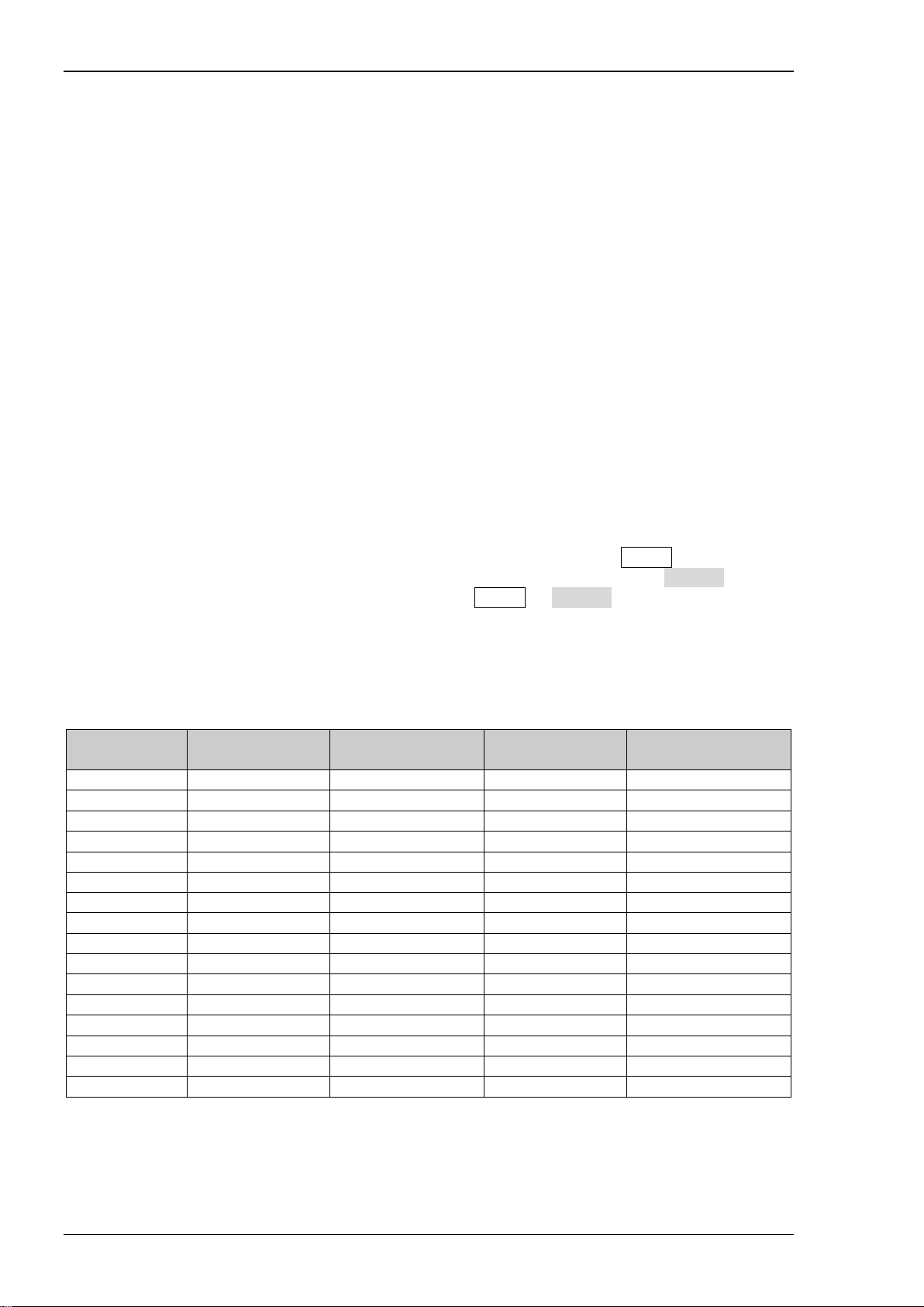
Format Conventions in this Manual:
Front Panel Key: denoted by “Text Box + Button Name (Bold)”. For example, Utility.
Menu Softkey: denoted by “Character Shading + Menu Wo rd (Bol d)”. For example, System.
Operation Step: denoted by an arrow “”. For example, Utility System.
Content Conventions in this Manual:
MSO4000/DS4000 series digital oscilloscope includes the following models. In this manual, MSO4054
is taken as an exam ple to illustrate the performance verification test methods. Unless otherwise note d,
the introductions in this manual are applicable to other models.
Model
MSO4000/DS4000 Performance Verification Guide
Page 11

Contents RIGOL
IX
Contents
Guaranty and Declaration ................................................................................................ I
General Safe ty Summary ................................................................................................ II
Safety Terms and Symbols ............................................................................................. IV
Allgemeine Sicherheits Informationen ............................................................................. V
Sicherheits Begriffe und Symbole ................................................................................. VII
Document Overview .................................................................................................... VIII
Chapter 1 Overview ................................................................................................... 1-1
Test Preparations ............................................................................................................ 1-1
Self-test .................................................................................................................. 1-1
Self-calibration ......................................................................................................... 1-1
Test Result Reco rd .......................................................................................................... 1-1
Specifications ................................................................................................................. 1-2
Chapter 2 Performance Verification Test ................................................................... 2-1
Impedance Test ............................................................................................................. 2-2
Specification ............................................................................................................ 2-2
Test Connection Diagra m .......................................................................................... 2-2
Test Procedures ....................................................................................................... 2-2
Test Record Form ..................................................................................................... 2-3
DC Gain Accuracy Test .................................................................................................... 2-4
Specification ............................................................................................................ 2-4
Test Connection Diagra m .......................................................................................... 2-4
Test Procedures ....................................................................................................... 2-4
Test Record Form ..................................................................................................... 2-6
Bandwidth Test .............................................................................................................. 2-8
Specification ............................................................................................................ 2-8
Test Connection Diagra m .......................................................................................... 2-8
Test Procedures ....................................................................................................... 2-8
Test Record Form ................................................................................................... 2-10
Bandwidth Limit Test .................................................................................................... 2-11
Specification .......................................................................................................... 2-11
Test Connection Diagra m ........................................................................................ 2-11
Test Procedures ..................................................................................................... 2-11
Test Record Form ................................................................................................... 2-15
Time Base Accuracy Test ............................................................................................... 2-18
Specification .......................................................................................................... 2-18
Test Connection Diagra m ........................................................................................ 2-18
Test Procedures ..................................................................................................... 2-18
Test Record Form ................................................................................................... 2-19
Zero Point Offset Test ................................................................................................... 2-20
Specification .......................................................................................................... 2-20
Test Connection Diagra m ........................................................................................ 2-20
Test Procedures ..................................................................................................... 2-20
Test Record Form ................................................................................................... 2-21
Appendix Test Record Form ............................................................................................. 1
MSO4000/DS4000 Performance Verification Guide
Page 12

Page 13

Chapter 1 Overview RIGOL
1-1
results in the copy so that the form can be used repeatedly.
Chapter 1 Overview
Test Preparations
The following preparations should be done before the test:
1. Self-test
2. Warm-up (make sure that the instrument has been running for at least 30 minutes)
3. Self-calibration
Self-test
When the oscilloscope is in p ower-on state, press the power key at the lower left corne r of the
front panel to start the oscilloscope. During the start-up, the instrument performs a series of self-test
items and you can hear the sound of relay switching. The welcome screen is displayed after the
self-test is finished. You can view the self-test results by pressing Utility System
SelfTestInfo.
If the self-test fails, make sure that the problems are found and resolved and do not perform
self-calibration and performance tests until the instrument passes the self-test.
Self-calibration
Make sure that the oscilloscope has been warmed up or running for more than 30 minutes before
performing self-calibration.
1. Connect the analog input channe ls and the external t rigger input channel of the oscilloscope to the
[Trig Out/Calibration] connector at the rear panel respectively using a one-to-five BNC (M)
cable.
2. Press Utility Self-Cal at the front panel and press Start to execute self-calibration.
3. The self-calibration lasts for about 30 minutes (20 minutes for dual-channel models). After the
self-calibration is f inished, the corresponding prompt message is displayed. At this point, please
restart the instrument.
4. Press Acquire; press Acquisition to select “Average” and press Averages to set it to 16.
5. Disconnect the input signa ls of al l the channels. Set the v ertical s cale of eac h c hannel to 2 mV/div
and view the offset of the wavefor m of each channel. If the offset is greater than 0.5div, you
should perform self-calibration again.
Test Result Record
Record and keep the test result of each test. In the Appendi x of this man ual, a test result record form
which lists all the test it ems and their corresponding performance limits as well as spaces for users to
record the test results, is provided.
Tip:
It is recommended that users photocop y th e te st r ec ord form before each test and record the test
MSO4000/DS4000 Performance Verification Guide
Page 14

RIGOL Chapter 1 Overview
1-2
minutes.
Specifications
The specification of each test item is provided in chapter 2. For other specifications, refer to
MSO4000/DS4000 User’s Guide
www.rigol.com).
Tip:
All the specifications are only valid when the oscilloscope has been warmed up for more than 30
or
MSO4000/DS4000 Data Sheet
(can b e d ownloa ded from
MSO4000/DS4000 Performance Verification Guide
Page 15

Chapter 2 Performance Verification T est RIGOL
2-1
DC output voltage range:
Fast edge signal rise time: ≤ 150 ps
The resistance measurement
reading
Test Cable
BNC (M)-Dual banana plug cable
--
Function/Arbitrary
Generator
Dual-BNC Cable
BNC (M)-BNC (M) cable
--
Chapter 2 Performance Verification Test
This chapter introduces the performance verification test methods and procedures of
MSO4000/DS4000 series digital oscilloscope by taking MSO 4054 as an example. Fluke 9500B is used
in this manual for t he te sts. You can also use other devices that fulfill the “Specification” in Table 2-1.
Table 2-1 Test Devices Required
Test Plan Device Specification Recommended Model
Plan 1
Plan 2
Note:
1. Make sure that the oscilloscope passes the self-test and self-calibration is performed before
executing the performance verification tests.
2. Make sure that the oscilloscope has bee n warmed u p for at lea st 30 minutes before exe cuting an y
of the following tests.
3. Please reset the instrument to the factory setting before or after executing any of the following
tests.
Oscilloscope
Calibrator
Digital Multimeter
Waveform
1 MΩ: 1 mV to 200 V
50 MΩ: 1 mV to 200 V
accuracy is higher than ±0.1% of
Frequency accuracy : ±1 ppm
Fluke 9500B
RIGOL DM3058/3068
RIGOL DG4162
MSO4000/DS4000 Performance Verification Guide
Page 16
RIGOL Chapter 2 Performance Verification Test
2-2
Input Impedance
1 MΩ: 0.99 MΩ to 1.01 MΩ
50 Ω: 49.25 Ω to 50.75 Ω
Fluke 9500B
MSO/DS4000
Impedance Test
Specification
Analog Channel
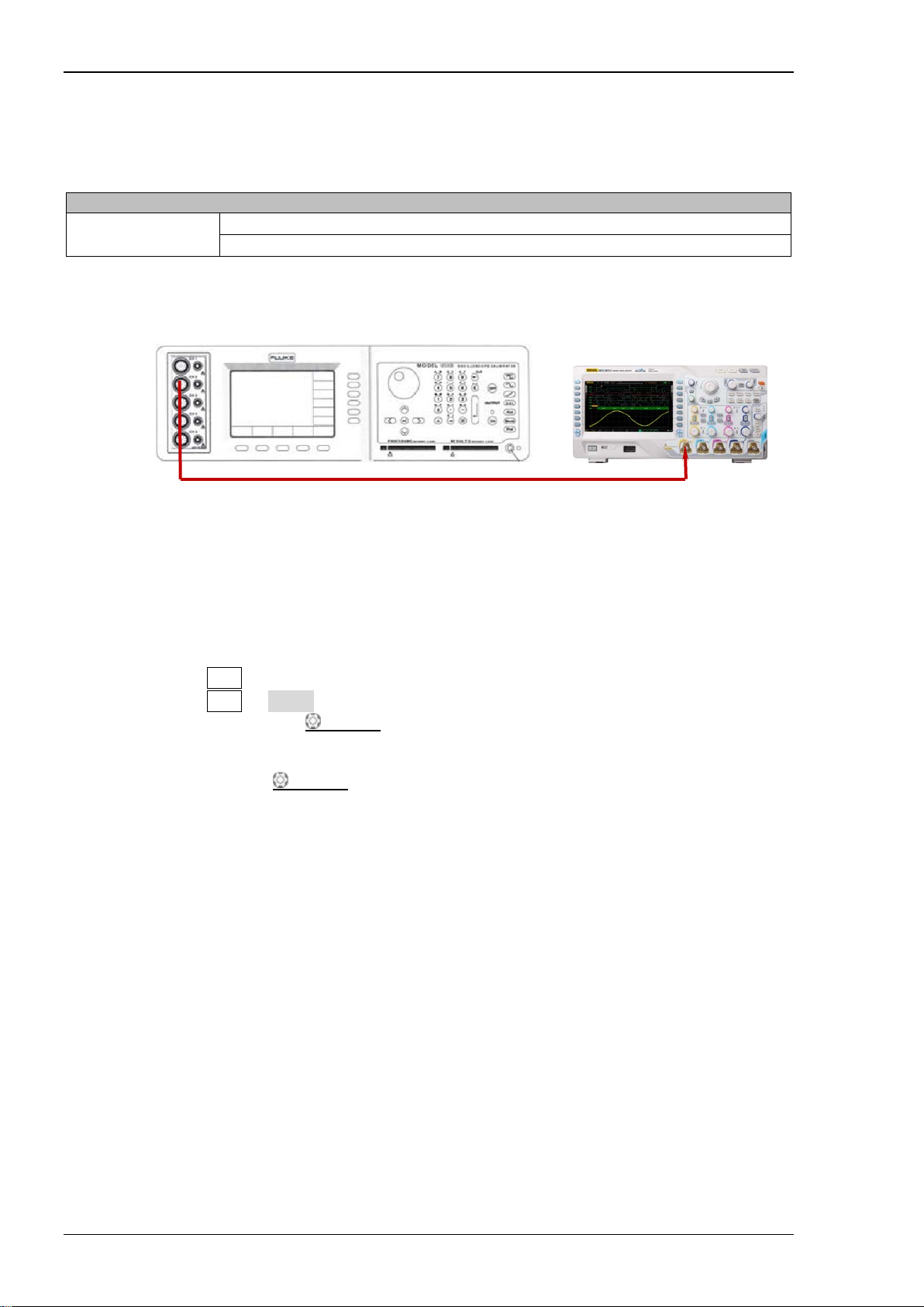
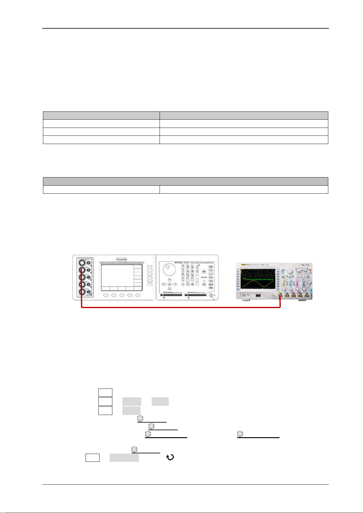
Test Connection Di ag ram
Figure 2-1 Impedance Test Connection Diagram
Test Procedures
1. Impedance test of CH1-CH4 when the input impedance is 1 MΩ
1) Connect the active signal t erminal of Fluk e 95 00B to CH1 of the oscil losc ope, as shown in the
f i gure above.
2) Configure the oscilloscope:
a) Press CH1 in the vertical control area (VERTICAL) at the front panel to turn on CH1.
b) Press CH1 Input to set the input impedance of CH1 to 1 MΩ.
c) Rotate VERTICAL SCALE to set the vertical scale of CH1 to 100 mV/div.
3) Turn on Fluke 9500B; set its imp edance to 1 MΩ and select the resistance measurement
function. Read and record the resistance measured.
4) Rotate VERTICAL
mV/div; read and record the resistance measured.
5) Turn off CH1. Measure the resistances of CH2, CH3 and CH4 respectively using the met hod
above and record the measurement results.
2. Impedance test of CH1-CH4 when the input impedance is 50 Ω
1) Connect the active signal t erminal of Fluk e 95 00B to CH1 of the oscil losc ope, as shown in the
f i gure above.
2) Configure the oscilloscope:
a) Turn on CH1.
b) Set the input impedance of CH1 to 50 Ω.
c) Set the vertical scale of CH1 to 100 mV/div.
3) Turn on Fluke 9500B; set its i mpedance to 50 Ω and select the resistance measurement
function. Read and record the resistance measured.
4) Adjust the vertical scale of CH1 of the oscilloscope to 500 mV/div; read and record the
resistance measured.
5) Turn off CH1. Measure the resistanc es of CH2, CH3 and CH4 respectively using the method
above and record the measurement results.
SCALE to adjust the vertical scale of CH1 of the oscilloscope to 500
MSO4000/DS4000 Performance Verification Guide
Page 17

Chapter 2 Performance Verification T est RIGOL
2-3
Channel
Vertical Scale
Test Result
Limit
Pass/Fail
100 mV/div
500 mV/div
100 mV/div
500 mV/div
100 mV/div
500 mV/div
100 mV/div
500 mV/div
Channel
Vertical Scale
Test Result
Limit
Pass/Fail
100 mV/div
500 mV/div
100 mV/div
500 mV/div
100 mV/div
500 mV/div
100 mV/div
500 mV/div
Channel
Input Impedance
Test Result
Limit
Pass/Fail
3. Impedance test of the [EXT TRIG] channel
1) Disconnect the connections of the four input channels.
2) Connect the external trigger input channel [EXT TRIG] with the active signal terminal of
Fluke 9500B.
3) Press Utility Extimpedance on the oscilloscope to set the input impedance of the
external trigger channel to 1 MΩ.
4) Turn on Fluke 9500B; set its impedanc e t o 1 MΩ and select the resistance measurement
function. Read and record the resistance measured.
5) Press Utility Extimpedance on the oscilloscope to set the input impedance of the
external trigger channel to 50 Ω.
6) Set the impedance of Fluke 9500B to 50 Ω. Read and record the resistance measured.
Test Record Form
CH1-CH4 (1 MΩ Input Impedance)
CH1
CH2
0.99 MΩ to 1.01 MΩ
CH3
CH4
CH1-CH4 (50 Ω Input Impedance)
CH1
CH2
CH3
CH4
External Trigger Channel
1 MΩ 0.99 MΩ to 1.01 MΩ
EXT TRIG
50 Ω 49.25 Ω to 50.75 Ω
49.25 Ω to 50.75 Ω
MSO4000/DS4000 Performance Verification Guide
Page 18

RIGOL Chapter 2 Performance Verification Test
2-4
DC Gain Accuracy
Specification
±2% × Full Scale
[1]
Fluke 9500B
MSO/DS4000
DC Gain Accuracy Test
Specification
[1]
Note
Test Connection Di ag ram
Test Procedures
1. DC gain accuracy test when the input impedance is 50 Ω
: Full Scale = 8 × Current Vertical Scale.
Figure 2-2 DC Gain Accuracy Test Connection Diagram
1) Connect the active signal t erminal of Fluk e 95 00B to CH1 of the oscil losc ope, as shown in the
f i gure above.
2) Turn on Fluke 9500B and set its impedance to 50 Ω.
3) Output a DC signal with +3 mV
voltage (Vout1) via Fluke 9500B.
DC
4) Configure the oscilloscope:
a) Press CH1 in the vertical control area (VERTICAL) at the front panel to turn on CH1.
b) Press CH1 Probe Ratio to set the probe attenuation ratio to “1X”.
c) Press CH1 Input to set the input impedance of CH1 to 50 Ω.
d) Rotate VERTICAL SCALE to set the vertical scale to 1 mV/div.
e) Rotate HORIZONTAL SCALE to set the horizontal time base to 2 ms.
f) Press VERTICAL POSITION to set the vertical position to 0.
g) Press Acquire Acquisition and use to select “Average” acquisition mode; press
Averages and use to set the n umb er of averages to 32.
5) Press MENU Vavg at the left side of the screen of the os cilloscope to turn o n the avera ge
measurement function. Read and record Vavg1.
6) Adjust Fluke 9500B to make it output a DC signal with -3 mVDC voltage (Vout2).
7) Press MENU Vavg at t he left side of the sc reen of the oscillosco pe to turn on the a vera ge
measurement function. Read and record Vavg2.
8) Calculate the relative error of this vertical scale: |(Vavg1 - Vavg2) - (Vout1 -
Vout2)|/Full Scale × 100%.
9) Keep the other settings of the oscilloscope unchanged:
a) Set the ver tica l sca le to 2 mV/div, 5 mV/div, 1 0 mV/div, 20 mV/div, 50 mV/div, 100
mV/div, 200 mV/div, 500 mV/div and 1 V/div respectively.
b) Adjust the output voltage of Fluke 9500B to 3 × the current vertical scale and -3 × the
current vertical scale respectively.
c) Repeat steps 3) to 7) and record the test results.
d) Calculate the relative error of each vertical scale: |(Vavg1 - Vavg2) - (Vout1 -
Vout2)|/Full Scale × 100%.
10) Turn off CH1. Test the relative error of each scale of CH2, CH3 and CH4 respectively using the
MSO4000/DS4000 Performance Verification Guide
Page 19

Chapter 2 Performance Verification T est RIGOL
2-5
method above and record the test results.
2. DC gain accuracy test when the input impedance is 1 MΩ
1) Connect the active signal t erminal of Fluk e 95 00B to CH1 of the oscil losc ope, as shown in the
f i gure above.
2) Set the input impedance of Fluke 9500B to 1 MΩ.
3) Output a DC signal with +3 mV
voltage (Vout1) via Fluke 9500B.
DC
4) Configure the oscilloscope:
a) Turn on CH1.
b) Set the probe attenuation ratio to “1X”.
c) Set the input impedance of CH1 to 1 MΩ.
d) Repeat d) to g) in step 4) in DC gain accuracy test when the input impedance is
50 Ω.
5) Test the relativ e error of e ach scale of C H1 (add the tests of 2 V/div and 5 V/div) according to
steps 5) to 9) in DC gain accuracy test when the input impedance is 50 Ω and record
the test results.
6) T urn off CH1. Test the relative error of each s cale of CH2, CH3 and CH4 respectively using the
method above and record the test results.
MSO4000/DS4000 Performance Verification Guide
Page 20

RIGOL Chapter 2 Performance Verification Test
2-6
Vertical
Scale
Test Result
Vavg1
Vavg2
Calculation Result
[1]
1 mV/div
2 mV/div
5 mV/div
10 mV/div
20 mV/div
50 mV/div
100 mV/div
200 mV/div
500 mV/div
1 V/div
1 mV/div
2 mV/div
5 mV/div
10 mV/div
20 mV/div
50 mV/div
100 mV/div
200 mV/div
500 mV/div
1 V/div
1 mV/div
2 mV/div
5 mV/div
10 mV/div
20 mV/div
50 mV/div
100 mV/div
200 mV/div
500 mV/div
1 V/div
1 mV/div
2 mV/div
5 mV/div
10 mV/div
20 mV/div
50 mV/div
100 mV/div
200 mV/div
500 mV/div
1 V/div
Test Record Form
50 Ω Input Impedance
Channel
CH1
CH2
Limit Pass/Fail
≤ 2%
CH3
CH4
[1]
Note
are 3 × the current vertical scale and -3 × the current vertical scale respectively.
: The calculation formula is |(Vavg1 - Vavg2) - (Vout1 - Vout2)|/Full Scale × 100%; wherein, Vout1 and Vout2
MSO4000/DS4000 Performance Verification Guide
Page 21

Chapter 2 Performance Verification T est RIGOL
2-7
Vertical
Scale
Test Result
Vavg1
Vavg2
Calculation Result
[1]
1 mV/div
2 mV/div
5 mV/div
10 mV/div
20 mV/div
50 mV/div
100 mV/div
200 mV/div
500 mV/div
1 V/div
2 V/div
5 V/div
1 mV/div
2 mV/div
5 mV/div
10 mV/div
20 mV/div
50 mV/div
100 mV/div
200 mV/div
500 mV/div
1 V/div
2 V/div
5 V/div
1 mV/div
2 mV/div
5 mV/div
10 mV/div
20 mV/div
50 mV/div
100 mV/div
200 mV/div
500 mV/div
1 V/div
2 V/div
5 V/div
1 mV/div
2 mV/div
5 mV/div
10 mV/div
20 mV/div
50 mV/div
100 mV/div
200 mV/div
500 mV/div
1 V/div
2 V/div
5 V/div
1 MΩ Input Impedance
Channel
CH1
CH2
Limit Pass/Fail
CH3
CH4
≤ 2%
[1]
Note
are 3
× the current vertical scale and -3 × the current vertical scale respectively.
MSO4000/DS4000 Performance Verification Guide
: The calculation formula is |(Vavg1 - Vavg2) - (Vout1 - Vout2)|/Full Scale × 100%; wherein, Vout1 and Vout2
Page 22

RIGOL Chapter 2 Performance Verification Test
2-8
Bandwidth
Amplitude Loss
[1]
-3 dB to 1 dB
Fluke 9500B
MSO/DS4000
Bandwidth Test
The bandwidth test verif ies the bandwidth performance of the oscilloscope by testing the amplitude
loss of the oscilloscope under test at full bandwidth.
Specification
[1]
Note
effective value at 1MHz and Vrms2 is the measurement result of amplitude effective value at full bandwidth.
Test Connection Di ag ram
: Amplitude Loss (dB) = 20 × lg (Vrms2/Vrms1); wherein, Vrms1 is the measurement result of amplitude
Figure 2-3 Bandwidth Test Connection Diagram
Test Procedures
1. Connect the active signal terminal of Fluk e 950 0B to CH1 of the oscilloscope, as shown in the
f i gure above.
2. Turn on Fluke 9500B and set its i mpedance to 5 0 Ω.
3. Configure the oscilloscope:
1) Press CH1 in the vertical contr ol area (VERTICAL) at the front panel to turn on CH1.
2) Press CH1 Probe Ratio to set the probe attenuation ratio to “1X”.
3) Press CH1 Input to set the input impedance of CH1 to 50 Ω.
4) Rotate HORIZONTAL SCALE to set the horizontal time base to 500 ns.
5) Rotate VERTICAL SCALE to set the vertical scale to 100 mV/div.
6) Press HORIZONTAL POSITION and VERTICAL POSITION respectively to set the
horizontal position and vertical position to 0.
7) Press TRIGGER LEVEL to set the trigger level to 0 V.
4. Output a Sine with 1 MHz frequency and 600 mVpp amplitude via Fluke 9500B.
5. Press MENU Vrms-N at the left side of the screen of the oscilloscope to turn on the effective
value measurement function. Read and record Vrms1.
6. Output a Sine with 500 MHz frequency (the setting value is different for different model of
oscilloscope under test; please refer to Table 2-2) and 600 mVpp amplitude via Fluke 9500B.
MSO4000/DS4000 Performance Verification Guide
Page 23

Chapter 2 Performance Verification T est RIGOL
2-9
Model
Full Bandwidth
Horizontal Time Base
MSO405X/DS405X
500 MHz
1 ns
MSO403X/DS403X
350 MHz
2 ns
MSO402X/DS402X
200 MHz
5 ns
MSO401X/DS401X
100 MHz
5 ns
Table 2-2 Setting Value of the Oscilloscope under Test
7. Rotate HORIZONTAL
different for different model of oscilloscope under test; please refer to
SCALE to set the horizontal time base to 1 ns (the setting value is
Table 2-2).
8. Press MENU Vrms-N at the left side of the screen of the oscilloscope to turn on the effective
value measurement function. Read and record Vrms2.
9. Calculate the amplitude loss: Amplitude Loss (dB) = 20 × lg (Vrms2/Vrms1).
10. Keep the other settings of the oscilloscope in step 3 unchanged and set the vertical scale to 200
mV/div.
11. Output a Sine with 1 MHz frequency and 1.2 Vpp amplitude via Fluke 9500B.
12. Repeat step 5.
13. Output a Sine with 500 MHz frequency (the setting value is different for different model of
oscilloscope under test; please refer to Table 2-2) and 1.2 Vpp amplitude via Fluke 9500B.
14. Repeat steps 7 to 9.
15. Keep the other settings of the oscilloscope in step 3 unchanged and set the vertical scale to 500
mV/div.
16. Output a Sine with 1 MHz frequency and 3 Vpp amplitude via Fluke 9500B.
17. Repeat step 5.
18. Output a Sine with 500 MHz frequency (the setting value is different for different mod el of
oscilloscope under test; please refer to Table 2-2) and 3 Vpp amplitude via Fluke 9500B.
19. Repeat steps 7 to 9.
20. Turn off CH1. Test CH2, CH3 and CH4 using the method above respectively and record the test
results.
MSO4000/DS4000 Performance Verification Guide
Page 24

RIGOL Chapter 2 Performance Verification Test
2-10
Vertical
Test Result
Vrms1
Vrms2
Amplitude Loss
[1]
100 mV/div
200 mV/div
500 mV/div
100 mV/div
200 mV/div
500 mV/div
100 mV/div
200 mV/div
500 mV/div
100 mV/div
200 mV/div
500 mV/div
Test Record Form
Channel
CH1
CH2
CH3
CH4
[1]
Note
: Amplitude Loss (dB) = 20 × lg (Vrms2/Vrms1).
Scale
Limit Pass/Fail
-3 dB to 1 dB
MSO4000/DS4000 Performance Verification Guide
Page 25
Chapter 2 Performance Verification T est RIGOL
2-11
Model
Bandwidth Limit
MSO405X/MSO403X/DS405X/DS403X
20 MHz/100 MHz/200 MHz
MSO402X/DS402X
20 MHz/100 MHz
MSO401X/DS401X
20 MHz
Bandwidth Limit
Amplitude Loss
[1]
-3 dB to 1 dB
Fluke 9500B
MSO/DS4000
Bandwidth Limit Test
The bandwidth limit test verif ies the 20 MHz bandwidth limit function, 100 MHz bandwidth limit
function and 200 MHz bandwidth limit function of the oscilloscope respectively by testing the
amplitude losses of the oscilloscope under test at the bandwidth limits.
For different models of oscilloscopes, the bandwidth limits are different, as shown in the table below.
Table 2-3 Bandwidth Limits of the Oscilloscope under Test
Specification
[1]
Note
measurement result of amplitude effective value at 1MHz; Vrms2 is the measurement result of amplitude effective
value at the bandwidth limit; Vrms3 is the measurement result of amplitude effective value when the frequency is
greater than the bandwidth limit.
Test Connection Di ag ram
: Amplitude Loss (dB) = 20 × lg (Vrmsn/Vrms1). Wherein, Vrmsn represents Vrms2 or Vrms3; Vrms1 is the
Figure 2-4 Bandwidth Limit Test Connection Diagram
Test Procedures
1. 20 MHz bandwid t h li mit test
1) Connect the active signal t erminal of Fluke 95 00B to CH1 of t he oscill oscope , a s shown in the
f i gure above.
2) Turn on Fluke 9500B and set its impedance to 50 Ω.
3) Configure the oscilloscope:
a) Press CH1 in the vertical control area (VERTICAL) at the front panel to turn on CH1.
b) Press CH1 Probe Ratio to set the probe attenuation ratio to “1X”.
c) Press CH1 Input to set the inpu t imp edance of CH1 to 50 Ω.
d) Rotate VERTICAL SCALE to set the vertical scale to 100 mV/div.
e) Rotate HORIZONTAL SCALE to set the horizontal time base to 500 ns.
f) Press HORIZONTAL POSITION and VERTICAL POSITION r e sp e ctively to
set the horizontal position and vertical position to 0.
g) Press TRIGGER LEVEL to set th e trigg er le vel to 0 V.
4) Press CH1 BW Limit and use to set th e bandwidth limi t to “20 M”.
5) Output a Sine with 1 MHz frequency and 600 mVpp amplitude via Fluke 9500B.
MSO4000/DS4000 Performance Verification Guide
Page 26

RIGOL Chapter 2 Performance Verification Test
2-12
6) Press MENU Vrms-N at the left side of the screen of the oscilloscope to turn on the
effective value measurement function. Read and record Vrms1.
7) Output a Sine with 20 MHz frequency and 600 mVpp amplitude via Fluke 9500B.
8) Rotate HORIZONTAL
SCALE to set the horizontal time base to 50 ns.
9) Press MENU Vrms-N at the left side of the screen of the oscilloscope to turn on the
effective value measurement function. Read and record Vrms2.
10) Calculate the amplitude loss: Amplitude Loss (dB) = 20 × lg (Vrms2/Vrms1) and
compare the result with the specification. At this point, the amplitude loss should be within
the specification range.
11) Output a Sine with 50 MHz frequency and 600 mVpp amplitude via Fluke 9500B.
12) Rotate HORIZONTAL
SCALE to set the horizontal time base to 20 ns.
13) Press MENU Vrms-N at the left side of the screen of the oscilloscope to turn on the
effective value measurement function. Read and record Vrms3.
14) Calculate the amplitude loss: Amplitude Loss (dB) = 20 × lg (Vrms3/Vrms1). At this
point, the amplitude loss should be lower than -3 dB.
15) Keep the other set tings of the oscilloscope in s tep 3) unchanged and set the ve rtical scale to
200 mV/div.
16) Output a Sine with 1 MHz frequency and 1.2 Vpp amplitude via Fluke 9500B.
17) Repeat step 6).
18) Output a Sine with 20 MHz frequency and 1.2 Vpp amplitude via Fluke 9500B.
19) Repeat steps 8) to 10).
20) Output a Sine with 50 MHz frequency and 1.2 Vpp amplitude via Fluke 9500B.
21) Repeat steps 12) to 14).
22) Keep the other settings of the oscilloscope in step 3) uncha nge d and set the vertical scale to
500 mV/div.
23) Output a Sine with 1 MHz frequency and 3 Vpp amplitude via Fluke 9500B.
24) Repeat step 6).
25) Output a Sine with 20 MHz frequency and 3 Vpp amplitude via Fluke 9500B.
26) Repeat steps 8) to 10).
27) Output a Sine with 50 MHz frequency and 3 Vpp amplitude via Fluke 9500B.
28) Repeat steps 12 to 14.
29) Turn off CH1. Test CH2, CH3 and CH4 respectively using the method above.
2. 100 MHz bandwidth limit test
1) Connect the active signal terminal of Fluke 9500B to CH1 of the oscilloscope, as shown in
Figure 2-4.
2) Turn on Fluke 9500B and set its impedance to 50 Ω.
3) Configure the oscilloscope:
a) Press CH1 in the vertical control area (VERTICAL) at the front panel to turn on CH1.
b) Press CH1 Probe Ratio to set the probe attenuation ratio to “1X”.
c) Press CH1 Input to set the inpu t imp edance of CH1 to 50 Ω.
d) Rotate VERTICAL SCALE to set the vertical scale to 100 mV/div.
e) Rotate HORIZONTAL SCALE to set the horizontal time base to 500 ns.
f) Press HORIZONTAL POSITION and VERTICAL POSITION respecti vely to
set the horizontal position and vertical position to 0.
g) Press TRIGGER LEVEL to set th e trigg er le vel to 0 V.
4) Press CH1 BW Limit and use to set th e bandwidth limi t to “100 M”.
5) Output a Sine with 1 MHz frequency and 600 mVpp amplitude via Fluke 9500B.
6) Press MENU Vrms-N at the left side of the screen of the oscilloscope to turn on the
effective value measurement function. Read and record Vrms1.
7) Output a Sine with 100 MHz frequency and 600 mVpp amplitude via Fluke 9500B.
8) Rotate HORIZONTAL
SCALE to set the horizontal time base to 10 ns.
9) Press MENU Vrms-N at the left side of the screen of the oscilloscope to turn on the
effective value measurement function. Read and record Vrms2.
10) Calculate the amplitude loss: Amplitude Loss (dB) = 20 × lg (Vrms2/Vrms1) and
MSO4000/DS4000 Performance Verification Guide
Page 27

Chapter 2 Performance Verification T est RIGOL
2-13
compare the result with the specification. At this point, the amplitude loss should be within
the specification range.
11) Output a Sine with 200 MHz frequency and 600 mVpp amplitude via Fluke 9500B.
12) Rotate HORIZONTAL
SCALE to set the horizontal time base to 5 ns.
13) Press MENU Vrms-N at the left side of the screen of the oscilloscope to turn on the
effective value measurement function. Read and record Vrms3.
14) Calculate the amplitude loss: Amplitude Loss (dB) = 20 × lg (Vrms3/Vrms1). At this
point, the amplitude loss should be lower than -3 dB.
15) Keep the other settings of the oscilloscope in step 3) unchanged and set the vertical scale to
200 mV/div.
16) Output a Sine with 1 MHz frequency and 1.2 Vpp amplitude via Fluke 9500B.
17) Repeat step 6).
18) Output a Sine with 100 MHz frequency and 1.2 Vpp amplitude via Fluke 9500B.
19) Repeat steps 8) to 10).
20) Output a Sine with 200 MHz frequency and 1.2 Vpp amplitude via Fluke 9500B.
21) Repeat steps 12) to 14).
22) Keep the other set tings of the oscilloscope in s tep 3) unchanged and set the ve rtical scale to
500 mV/div.
23) Output a Sine with 1 MHz frequency and 3 Vpp amplitude via Fluke 9500B.
24) Repeat step 6).
25) Output a Sine with 100 MHz frequency and 3 Vpp amplitude via Fluke 9500B.
26) Repeat steps 8) to 10).
27) Output a Sine with 200 MHz frequency and 3 Vpp amplitude via Fluke 9500B.
28) Repeat steps 12) to 14).
29) Turn off CH1. Test CH2, CH3 and CH4 respectively using the method above.
3. 200 MHz bandwidth limit test
1) Connect the active signal terminal of Fluke 9500B to CH1 of the oscilloscope, as shown in
Figure 2-4.
2) Turn on Fluke 9500B and set its impedance to 50 Ω.
3) Configure the oscilloscope:
a) Press CH1 in the vertical control area (VERTICAL) at the front panel to turn on CH1.
b) Press CH1 Probe Ratio to set the probe attenuation ratio to “1X”.
c) Press CH1 Input to set the input impedance of CH1 to 50 Ω.
d) Rotate VERTICAL SCALE to set the vertical scale to 100 mV/div.
e) Rotate HORIZONTAL SCALE to set the horizontal time base to 500 ns.
f) Press HORIZONTAL POSITION and VERTICAL POSITION respecti vely to
set the horizontal position and vertical position to 0.
g) Press TRIGGER LEVEL to set th e trigg er le vel to 0 V.
4) Press CH1 BW Limit and use to set th e bandwidth limi t to “200 M”.
5) Output a Sine with 1 MHz frequency and 600 mVpp amplitude via Fluke 9500B.
6) Press MENU Vrms-N at the left side of the screen of the oscilloscope to turn on the
effective value measurement function. Read and record Vrms1.
7) Output a Sine with 200 MHz frequency and 600 mVpp amplitude via Fluke 9500B.
8) Rotate HORIZONTAL
SCALE to set the horizontal time base to 5 ns.
9) Press MENU Vrms-N at the left side of the screen of the oscilloscope to turn on the
effective value measurement function. Read and record Vrms2.
10) Calculate the amplitude loss: Amplitude Loss (dB) = 20 × lg (Vrms2/Vrms1) and
compare the result with the specification. At this point, the amplitude loss should be within
the specification range.
11) Output a Sine with 400 MHz frequency and 600 mVpp amplitude via Fluke 9500B.
12) Rotate HORIZONTAL
SCALE to set the horizontal time base to 5 ns.
13) Press MENU Vrms-N at the left side of the screen of the oscilloscope to turn on the
effective value measurement function. Read and record Vrms3.
14) Calculate the amplitude loss: Amplitude Loss (dB) = 20 × lg (Vrms3/Vrms1). At this
MSO4000/DS4000 Performance Verification Guide
Page 28

RIGOL Chapter 2 Performance Verification Test
2-14
point, the amplitude loss should be lower than -3 dB.
15) Keep the other set tings of the oscilloscope in s tep 3) unchanged and set the ve rtical scale to
200 mV/div.
16) Output a Sine with 1 MHz frequency and 1.2 Vpp amplitude via Fluke 9500B.
17) Repeat step 6).
18) Output a Sine with 200 MHz frequency and 1.2 Vpp amplitude via Fluke 9500B.
19) Repeat steps 8) to 10).
20) Output a Sine with 400 MHz frequency and 1.2 Vpp amplitude via Fluke 9500B.
21) Repeat steps 12) to 14).
22) Keep the other set tings of the oscilloscope in s tep 3) unchanged and set the ve rtical scale to
500 mV/div.
23) Output a Sine with 1 MHz frequency and 3 Vpp amplitude via Fluke 9500B.
24) Repeat step 6).
25) Output a Sine with 200 MHz frequency and 3 Vpp amplitude via Fluke 9500B.
26) Repeat steps 8) to 10).
27) Output a Sine with 400 MHz frequency and 3 Vpp amplitude via Fluke 9500B.
28) Repeat steps 12) to 14).
29) Turn off CH1. Test CH2, CH3 and CH4 respectively using the method above.
MSO4000/DS4000 Performance Verification Guide
Page 29

Chapter 2 Performance Verification T est RIGOL
2-15
Vertical
Scale
Test Result
Pass/
Fail
Vrms1
Vrms2
Vrms3
Amplitude
Loss A1
Amplitude
Loss A2
Amplitude
Loss A1
Amplitude
Loss A2
Amplitude
Loss A1
Amplitude
Amplitude
Loss A1
Amplitude
Loss A2
Amplitude
Loss A1
Amplitude
Loss A2
Amplitude
Loss A1
Amplitude
Amplitude
Loss A1
Amplitude
Loss A2
Amplitude
Loss A1
Amplitude
Loss A2
Amplitude
Loss A1
Amplitude
Loss A2
Amplitude
Amplitude
Loss A2
Amplitude
Loss A1
Amplitude
Loss A2
Amplitude
Loss A1
Amplitude
Loss A2
Test Record Form
20 MHz Bandwidth Limit Test
Channel
CH1
CH2
100
mV/div
200
mV/div
500
mV/div
100
mV/div
200
mV/div
500
mV/div
Calculation Result Limit
-3 dB to 1 dB
≤-3 dB
-3 dB to 1 dB
≤-3 dB
-3 dB to 1 dB
≤-3 dB
-3 dB to 1 dB
≤-3 dB
-3 dB to 1 dB
≤-3 dB
-3 dB to 1 dB
≤-3 dB
Loss A2
Loss A2
[1]
[2]
[1]
[2]
[1]
[2]
[1]
[2]
[1]
[2]
[1]
[2]
Note
Note
100
mV/div
CH3
200
mV/div
500
mV/div
100
mV/div
CH4
200
mV/div
500
mV/div
[1]
: Amplitude Loss A1 (dB) = 20 × lg (Vrms2/Vrms1).
[2]
: Amplitude Loss A2 (dB) = 20 × lg (Vrms3/Vrms1).
Loss A1
[1]
[2]
[1]
[2]
[1]
[2]
[1]
[2]
[1]
[2]
[1]
[2]
-3 dB to 1 dB
≤-3 dB
-3 dB to 1 dB
≤-3 dB
-3 dB to 1 dB
≤-3 dB
-3 dB to 1 dB
≤-3 dB
-3 dB to 1 dB
≤-3 dB
-3 dB to 1 dB
≤-3 dB
MSO4000/DS4000 Performance Verification Guide
Page 30

RIGOL Chapter 2 Performance Verification Test
2-16
Vertical
Scale
Test Result
Pass/
Fail
Vrms1
Vrms2
Vrms3
Amplitude
Loss A1
Amplitude
Amplitude
Loss A1
Amplitude
Loss A2
Amplitude
Loss A1
Amplitude
Loss A2
Amplitude
Loss A1
Amplitude
Loss A2
Amplitude
Loss A1
Amplitude
Loss A2
Amplitude
Loss A1
Amplitude
Loss A2
Amplitude
Loss A1
Amplitude
Loss A2
Amplitude
Amplitude
Loss A2
Amplitude
Loss A1
Amplitude
Loss A2
Amplitude
Loss A1
Amplitude
Loss A2
Amplitude
Loss A1
Amplitude
Amplitude
Loss A1
Amplitude
Loss A2
100 MHz Bandwidth Limit Test
Channel
CH1
CH2
100
mV/div
200
mV/div
500
mV/div
100
mV/div
200
mV/div
500
mV/div
Calculation Result Limit
-3 dB to 1 dB
≤-3 dB
-3 dB to 1 dB
≤-3 dB
-3 dB to 1 dB
≤-3 dB
-3 dB to 1 dB
≤-3 dB
-3 dB to 1 dB
≤-3 dB
-3 dB to 1 dB
≤-3 dB
Loss A2
[1]
[2]
[1]
[2]
[1]
[2]
[1]
[2]
[1]
[2]
[1]
[2]
Note
Note
100
mV/div
CH3
200
mV/div
500
mV/div
100
mV/div
CH4
200
mV/div
500
mV/div
[1]
: Amplitude Loss A1 (dB) = 20 × lg (Vrms2/Vrms1).
[2]
: Amplitude Loss A2 (dB) = 20 × lg (Vrms3/Vrms1).
Loss A1
Loss A2
[1]
[2]
[1]
[2]
[1]
[2]
[1]
[2]
[1]
[2]
[1]
[2]
-3 dB to 1 dB
≤-3 dB
-3 dB to 1 dB
≤-3 dB
-3 dB to 1 dB
≤-3 dB
-3 dB to 1 dB
≤-3 dB
-3 dB to 1 dB
≤-3 dB
-3 dB to 1 dB
≤-3 dB
MSO4000/DS4000 Performance Verification Guide
Page 31

Chapter 2 Performance Verification T est RIGOL
2-17
Vertical
Scale
Test Result
Pass/
Fail
Vrms1
Vrms2
Vrms3
Amplitude
Loss A1
Amplitude
Amplitude
Loss A1
Amplitude
Loss A2
Amplitude
Loss A1
Amplitude
Loss A2
Amplitude
Loss A1
Amplitude
Loss A2
Amplitude
Loss A1
Amplitude
Loss A2
Amplitude
Loss A1
Amplitude
Loss A2
Amplitude
Loss A1
Amplitude
Loss A2
Amplitude
Amplitude
Loss A2
Amplitude
Loss A1
Amplitude
Loss A2
Amplitude
Loss A1
Amplitude
Loss A2
Amplitude
Loss A1
Amplitude
Amplitude
Loss A1
Amplitude
Loss A2
200 MHz Bandwidth Limit Test
Channel
CH1
CH2
100
mV/div
200
mV/div
500
mV/div
100
mV/div
200
mV/div
500
mV/div
Calculation Result Limit
-3 dB to 1 dB
≤-3 dB
-3 dB to 1 dB
≤-3 dB
-3 dB to 1 dB
≤-3 dB
-3 dB to 1 dB
≤-3 dB
-3 dB to 1 dB
≤-3 dB
-3 dB to 1 dB
≤-3 dB
Loss A2
[1]
[2]
[1]
[2]
[1]
[2]
[1]
[2]
[1]
[2]
[1]
[2]
Note
Note
100
mV/div
CH3
200
mV/div
500
mV/div
100
mV/div
CH4
200
mV/div
500
mV/div
[1]
: Amplitude Loss A1 (dB) = 20 × lg (Vrms2/Vrms1).
[2]
: Amplitude Loss A2 (dB) = 20 × lg (Vrms3/Vrms1).
Loss A1
Loss A2
[1]
[2]
[1]
[2]
[1]
[2]
[1]
[2]
[1]
[2]
[1]
[2]
-3 dB to 1 dB
≤-3 dB
-3 dB to 1 dB
≤-3 dB
-3 dB to 1 dB
≤-3 dB
-3 dB to 1 dB
≤-3 dB
-3 dB to 1 dB
≤-3 dB
-3 dB to 1 dB
≤-3 dB
MSO4000/DS4000 Performance Verification Guide
Page 32

RIGOL Chapter 2 Performance Verification Test
2-18
Time Base Accuracy
[1]
Specification
≤ ±(4 ppm + Clock Drift
[2]
× Number of years that the instrument has
been used
)
Fluke 9500B
MSO/DS4000
Time Base Accura cy Test
Specification
[3]
[1]
Note
Note
Note
verification certificate provided when the instrument leaves factory.
Test Connection Di ag ram
: Typical.
[2]
: Clock drift is lower than or equal to ±2 ppm/year.
[3]
: For the number of years that the instrument has been used, please calculate according to the date in the
Figure 2-5 Time Base Accuracy Test Connection Diagram
Test Procedures
1. Connect the active signal terminal of Fluk e 950 0B to CH1 of the oscilloscope, as shown in the
f i gure above.
2. Turn on Fluke 9500B and set its i mpedance to 50 Ω.
3. Output a Sine with 10 MHz frequency and 1 Vpp amplitude via Fluke 9500B.
4. Configure the oscilloscope:
1) Press CH1 in the vertical control area (VERTICAL) at the front panel to turn on CH1.
2) Press CH1 Probe Ratio to set the probe attenuation ratio to “1X”.
3) Press CH1 Input to set the input impedance of CH1 to 50 Ω.
4) Rotate VERTICAL SCALE to set the vertical scale to 200 mV/div.
5) Press VERTICAL POSITION to set the vertical position to 0.
6) Rotate HORIZONTAL SCALE to set the horizontal time base to 10 ns.
7) Rotate HORIZONTAL POSITION to set the horizontal position to 1 ms.
5. Observe the s creen of the o scilloscope . Press Cursor Mode “Manual” to turn on t he manual
cursor functio n. Measure the offset (ΔT) of the middle point of the signal (namely the crossing
point of the rising edge of t he current signal and the trigger level line ) relative to the screen center
using manual cursor measurement and record the measurement result.
6. Calculate the time base accuracy ; namely the ratio of ΔT to the horizontal position of the
oscilloscope. For example, if the offset measured is 1 ns, the time base accuracy is 1 ns/1 ms=1
ppm.
7. Calculate the time base accuracy limit using the formula “±(4 ppm + 2 ppm/year × Number of
years that the instrument has been used).
MSO4000/DS4000 Performance Verification Guide
Page 33

Chapter 2 Performance Verification T est RIGOL
2-19
Channel
Test Result ΔT
Calculation Result
[1]
Limit
Pass/Fail
±(4 ppm + 2 ppm/year ×
instrument has been used
)
Test Record Form
CH1
[1]
Note
Note
verification certificate provided when the instrument leaves factory.
: Calculation Result = Test Result ΔT/1 ms.
[2]
: For the number of years that the instrument has been used, please calculate according to the date in the
Number of years that the
[2]
MSO4000/DS4000 Performance Verification Guide
Page 34

RIGOL Chapter 2 Performance Verification Test
2-20
Zero Point Offset
Specification
±0.5 div × Minimum Time Base Scale
Fluke 9500B
MSO/DS4000
Zero Point Offset Test
Zero point offset is defined as the offset of the crossing point of the waveform and trigger level line
relative to the trigger position, as shown in the figure below.
Specification
[1]
[1]
Note
MSO405X/DS405X, the minimum time base scale is 1 ns/div; for MSO403X/DS403X/MSO402X/DS402X, the minimum
time base scale is 2 ns/div; for MSO401X/DS401X, the minimum time base scale is 5 ns/div.
: For different models of oscilloscopes under test, the minimum time base scales are different. For
Test Connection Di ag ram
Figure 2-6 Zero Point Offset Test Connection Diagram
Test Procedures
1. Connect the active signal terminal of Fluke 9500B to CH1 of the oscilloscope, as shown in the
f i gure above.
2. Turn on Fluke 9500B and set its i mpedance to 5 0 Ω.
3. Output a fast edge signal with 150 ps rise time and 1.2 V amplitude via Fluke 9500B.
4. Configure the oscilloscope:
1) Press CH1 in the vertical control area (VERTICAL) at the front panel to turn on CH1.
2) Press CH1 Probe Ratio to set the probe attenuation r a t i o t o “1X”.
3) Press CH1 Input to set the input impedance of CH1 to 50 Ω.
4) Rotate VERTICAL SCALE to set the vertical scale to 200 mV/div.
5) Rotate HORIZONTAL SCALE to set the horizontal time base to 1 ns (the setting v alue is
MSO4000/DS4000 Performance Verification Guide
Page 35

Chapter 2 Performance Verification T est RIGOL
2-21
Model
Horizontal Time Base
MSO405X/DS405X
1 ns/div
MSO403X/DS403X/MSO402X/DS402X
2 ns/div
MSO401X/DS401X
5 ns/div
Fast Edge Signal
Vertical
1.2 Vpp
200 mV/div
3 Vpp
500 mV/div
1.2 Vpp
200 mV/div
3 Vpp
500 mV/div
1.2 Vpp
200 mV/div
3 Vpp
500 mV/div
1.2 Vpp
200 mV/div
3 Vpp
500 mV/div
differen t for different model of oscilloscope under test; please refer to Table 2-4).
Table 2-4 Horizontal Time Base Setting Value for the Oscilloscope under Test
6) Press TRIGGER LEVEL to adjust the trigger level to the middle of the screen.
7) Rotate HORIZONTAL POSITION and VERTICAL POSITION respe ctively to
adjust the horizontal position and vertical p os i t i on properly.
5. Observe the s creen of the o scilloscope . Press Cursor Mode “Manual” to turn on t he manual
cursor function. Measure the zero point offset using manual cursor measurement and record the
measurement result.
6. Keep the oth er settings of the oscilloscope unchanged and set the vertical scale to 500 mV/div.
7. Output a fast edge signal with 150 ps rise time and 3 V amplitude via Fluke 9500B.
8. Measure the zero point off set according to the method above a nd record the measurement result.
9. Turn off CH1. Test CH2, CH3 and CH4 respectively according to the method above and record the
test results.
Test Record Form
Channel
Amplitude
Scale
Test Result Limit
Pass/Fail
CH1
CH2
≤ 0.5 div ×
Minimum Time
[1]
CH3
Base Scale
CH4
[1]
Note
minimum time base scale is 1 ns/div; for MSO403X/DS403X/MSO402X/DS402X, the minimum time base scale is 2
ns/div; for MSO401X/DS401X, the minimum time base scale is 5 ns/div.
: For different models of oscilloscopes, the minimum time base scales are different. For MSO405X/DS405X, the
MSO4000/DS4000 Performance Verification Guide
Page 36

Page 37

Appendix Test Record Form RIGOL
1
Model:
Tested by:
Test Date:
Channel
Vertical Scale
Test Result
Limit
Pass/Fail
100 mV/div
500 mV/div
100 mV/div
500 mV/div
100 mV/div
500 mV/div
100 mV/div
500 mV/div
Channel
Vertical Scale
Test Result
Limit
Pass/Fail
100 mV/div
500 mV/div
100 mV/div
500 mV/div
100 mV/div
500 mV/div
100 mV/div
500 mV/div
Channel
Input Impedance
Test Result
Limit
Pass/Fail
Appendix Test Record Form
RIGOL MSO4000/DS4000 Series Digital Oscilloscope
Performance Verification Test Record Form
Impedance Test
CH1-CH4 (1 MΩ Input Impedance)
CH1
CH2
0.99 MΩ to 1.01 MΩ
CH3
CH4
CH1-CH4 (50 Ω Input Impedance)
CH1
CH2
CH3
CH4
External Trigger Channel
1 MΩ 0.99 MΩ to 1.01 MΩ
EXT TRIG
50 Ω 49.25 Ω to 50.75 Ω
49.25 Ω to 50.75 Ω
MSO4000/DS4000 Performance Verification Guide
Page 38

RIGOL Appendix Test Record Form
2
Vertical
Test Result
Vavg1
Vavg2
Calculation Result
[1]
1 mV/div
2 mV/div
5 mV/div
10 mV/div
20 mV/div
50 mV/div
100 mV/div
200 mV/div
500 mV/div
1 V/div
1 mV/div
2 mV/div
5 mV/div
10 mV/div
20 mV/div
50 mV/div
100 mV/div
200 mV/div
500 mV/div
1 V/div
1 mV/div
2 mV/div
5 mV/div
10 mV/div
20 mV/div
50 mV/div
100 mV/div
200 mV/div
500 mV/div
1 V/div
1 mV/div
2 mV/div
5 mV/div
10 mV/div
20 mV/div
50 mV/div
100 mV/div
200 mV/div
500 mV/div
1 V/div
DC Gain Accuracy Test
50 Ω Input Impedance
Channel
CH1
CH2
Scale
Limit Pass/Fail
≤ 2%
CH3
CH4
[1]
Note
: The calculation formula is |(Vavg1 - Vavg2) - (Vout1 - Vout2)|/Full Scale × 100%; wherein, Vout1 and Vout2
are 3 × the current vertical scale and -3 × the current vertical scale respectively.
MSO4000/DS4000 Performance Verification Guide
Page 39

Appendix Test Record Form RIGOL
3
Vertical
Scale
Test Result
Vavg1
Vavg2
Calculation Result
[1]
1 mV/div
2 mV/div
5 mV/div
10 mV/div
20 mV/div
50 mV/div
100 mV/div
200 mV/div
500 mV/div
1 V/div
2 V/div
5 V/div
1 mV/div
2 mV/div
5 mV/div
10 mV/div
20 mV/div
50 mV/div
100 mV/div
200 mV/div
500 mV/div
1 V/div
2 V/div
5 V/div
1 mV/div
2 mV/div
5 mV/div
10 mV/div
20 mV/div
50 mV/div
100 mV/div
200 mV/div
500 mV/div
1 V/div
2 V/div
5 V/div
1 mV/div
2 mV/div
5 mV/div
10 mV/div
20 mV/div
50 mV/div
100 mV/div
200 mV/div
500 mV/div
1 V/div
2 V/div
5 V/div
1 MΩ Input Impedance
Channel
CH1
CH2
Limit Pass/Fail
≤ 2%
CH3
CH4
[1]
Note
are 3
: The calculation formula is |(Vavg1 - Vavg2) - (Vout1 - Vout2)|/Full Scale × 100%; wherein, Vout1 and Vout2
× the current vertical scale and -3 × the current vertical scale respectively.
MSO4000/DS4000 Performance Ve rification Guide
Page 40

RIGOL Appendix Test Record Form
4
Vertical
Scale
Test Result
Vrms1
Vrms2
Amplitude Loss
[1]
100 mV/div
200 mV/div
500 mV/div
100 mV/div
200 mV/div
500 mV/div
100 mV/div
200 mV/div
500 mV/div
100 mV/div
200 mV/div
500 mV/div
Bandwidth Test
Channel
CH1
CH2
CH3
CH4
[1]
Note
Limit Pass/Fail
-3 dB to 1 dB
: Amplitude Loss (dB) = 20 × lg (Vrms2/Vrms1).
MSO4000/DS4000 Performance Verification Guide
Page 41

Appendix Test Record Form RIGOL
5
Vertical
Test Result
Pass/
Vrms1
Vrms2
Vrms3
Amplitude
Loss A1
Amplitude
Loss A2
Amplitude
Loss A1
Amplitude
Loss A2
Amplitude
Loss A1
Amplitude
Loss A2
Amplitude
Loss A1
Amplitude
Loss A2
Amplitude
Loss A1
Amplitude
Loss A2
Amplitude
Loss A1
Amplitude
Loss A2
Amplitude
Loss A1
Amplitude
Loss A2
Amplitude
Loss A1
Amplitude
Loss A2
Amplitude
Loss A1
Amplitude
Loss A2
Amplitude
Loss A1
Amplitude
Loss A2
Amplitude
Loss A1
Amplitude
Loss A2
Amplitude
Loss A1
Amplitude
Loss A2
Bandwidth Limit Test
20 MHz Bandwidth Limit Test
Channel
CH1
CH2
Scale
100 mV/div
200 mV/div
500 mV/div
100 mV/div
200 mV/div
500 mV/div
100 mV/div
Calculation Result Limit
[1]
[2]
[1]
[2]
[1]
[2]
[1]
[2]
[1]
[2]
[1]
[2]
[1]
[2]
-3 dB to 1 dB
≤-3 dB
-3 dB to 1 dB
≤-3 dB
-3 dB to 1 dB
≤-3 dB
-3 dB to 1 dB
≤-3 dB
-3 dB to 1 dB
≤-3 dB
-3 dB to 1 dB
≤-3 dB
-3 dB to 1 dB
≤-3 dB
Fail
Note
Note
CH3
CH4
[1]
[2]
200 mV/div
500 mV/div
100 mV/div
200 mV/div
500 mV/div
: Amplitude Loss A1 (dB) = 20 × lg (Vrms2/Vrms1).
: Amplitude Loss A2 (dB) = 20 × lg (Vrms3/Vrms1).
[1]
[2]
[1]
[2]
[1]
[2]
[1]
[2]
[1]
[2]
-3 dB to 1 dB
≤-3 dB
-3 dB to 1 dB
≤-3 dB
-3 dB to 1 dB
≤-3 dB
-3 dB to 1 dB
≤-3 dB
-3 dB to 1 dB
≤-3 dB
MSO4000/DS4000 Performance Ve rification Guide
Page 42

RIGOL Appendix Test Record Form
6
Vertical
Scale
Test Result
Pass/
Fail
Vrms1
Vrms2
Vrms3
Amplitude
Loss A1
Amplitude
Loss A2
Amplitude
Loss A1
Amplitude
Loss A2
Amplitude
Loss A1
Amplitude
Loss A2
Amplitude
Loss A1
Amplitude
Loss A2
Amplitude
Loss A1
Amplitude
Loss A2
Amplitude
Loss A1
Amplitude
Loss A2
Amplitude
Loss A1
Amplitude
Loss A2
Amplitude
Loss A1
Amplitude
Loss A2
Amplitude
Loss A1
Amplitude
Loss A2
Amplitude
Loss A1
Amplitude
Loss A2
Amplitude
Loss A1
Amplitude
Loss A2
Amplitude
Loss A1
Amplitude
Loss A2
100 MHz Bandwidth Limit Test
Channel
CH1
CH2
100 mV/div
200 mV/div
500 mV/div
100 mV/div
200 mV/div
500 mV/div
100 mV/div
Calculation Result Limit
[1]
[2]
[1]
[2]
[1]
[2]
[1]
[2]
[1]
[2]
[1]
[2]
[1]
[2]
-3 dB to 1 dB
≤-3 dB
-3 dB to 1 dB
≤-3 dB
-3 dB to 1 dB
≤-3 dB
-3 dB to 1 dB
≤-3 dB
-3 dB to 1 dB
≤-3 dB
-3 dB to 1 dB
≤-3 dB
-3 dB to 1 dB
≤-3 dB
Note
Note
CH3
CH4
[1]
[2]
200 mV/div
500 mV/div
100 mV/div
200 mV/div
500 mV/div
: Amplitude Loss A1 (dB) = 20 × lg (Vrms2/Vrms1).
: Amplitude Loss A2 (dB) = 20 × lg (Vrms3/Vrms1).
[1]
[2]
[1]
[2]
[1]
[2]
[1]
[2]
[1]
[2]
-3 dB to 1 dB
≤-3 dB
-3 dB to 1 dB
≤-3 dB
-3 dB to 1 dB
≤-3 dB
-3 dB to 1 dB
≤-3 dB
-3 dB to 1 dB
≤-3 dB
MSO4000/DS4000 Performance Verification Guide
Page 43

Appendix Test Record Form RIGOL
7
Vertical
Scale
Test Result
Pass/
Fail
Vrms1
Vrms2
Vrms3
Amplitude
Loss A1
Amplitude
Loss A2
Amplitude
Loss A1
Amplitude
Loss A2
Amplitude
Loss A1
Amplitude
Loss A2
Amplitude
Loss A1
Amplitude
Loss A2
Amplitude
Loss A1
Amplitude
Loss A2
Amplitude
Loss A1
Amplitude
Loss A2
Amplitude
Loss A1
Amplitude
Loss A2
Amplitude
Loss A1
Amplitude
Loss A2
Amplitude
Loss A1
Amplitude
Loss A2
Amplitude
Loss A1
Amplitude
Loss A2
Amplitude
Loss A1
Amplitude
Loss A2
Amplitude
Loss A1
Amplitude
Loss A2
200 MHz Bandwidth Limit Test
Channel
CH1
CH2
100 mV/div
200 mV/div
500 mV/div
100 mV/div
200 mV/div
500 mV/div
100 mV/div
Calculation Result Limit
[1]
[2]
[1]
[2]
[1]
[2]
[1]
[2]
[1]
[2]
[1]
[2]
[1]
[2]
-3 dB to 1 dB
≤-3 dB
-3 dB to 1 dB
≤-3 dB
-3 dB to 1 dB
≤-3 dB
-3 dB to 1 dB
≤-3 dB
-3 dB to 1 dB
≤-3 dB
-3 dB to 1 dB
≤-3 dB
-3 dB to 1 dB
≤-3 dB
Note
Note
CH3
CH4
[1]
[2]
200 mV/div
500 mV/div
100 mV/div
200 mV/div
500 mV/div
: Amplitude Loss A1 (dB) = 20 × lg (Vrms2/Vrms1).
: Amplitude Loss A2 (dB) = 20 × lg (Vrms3/Vrms1).
[1]
[2]
[1]
[2]
[1]
[2]
[1]
[2]
[1]
[2]
-3 dB to 1 dB
≤-3 dB
-3 dB to 1 dB
≤-3 dB
-3 dB to 1 dB
≤-3 dB
-3 dB to 1 dB
≤-3 dB
-3 dB to 1 dB
≤-3 dB
MSO4000/DS4000 Performance Ve rification Guide
Page 44

RIGOL Appendix Test Record Form
8
Calculation
Result
Pass/
Fail
±(4 ppm + 2 ppm/year × Number of
used
)
Fast Edge Signal
1.2 Vpp
200 mV/div
3 Vpp
500 mV/div
1.2 Vpp
200 mV/div
3 Vpp
500 mV/div
1.2 Vpp
200 mV/div
3 Vpp
500 mV/div
1.2 Vpp
200 mV/div
3 Vpp
500 mV/div
Time Base Accuracy Test
Channel Test Result ΔT
CH1
[1]
Note
Note
: Calculation Result = Test Result ΔT/1 ms.
[2]
: For the number of years that the instrument has been used, please calculate according to the date in the
[1]
years that the instrument has been
[2]
Limit
verification certificate provided when the instrument leaves factory.
Zero Point Offset Test
Channel
Amplitude
Vertical Scale Test Result Limit
CH1
CH2
≤ 0.5 div ×
Minimum Time
CH3
Base Scale
CH4
[1]
Note
: For different models of oscilloscopes, the minimum time base scales are different. For MSO405X/DS405X, the
minimum time base scale is 1 ns/div; for MSO403X/DS403X/MSO402X/DS402X, the minimum time base scale is 2
ns/div; for MSO401X/DS401X, the minimum time base scale is 5 ns/div.
[1]
Pass/Fail
MSO4000/DS4000 Performance Verification Guide
 Loading...