

Rigol MSO4000 Series Digital Oscilloscope, DS4000 Series Digital Oscilloscope Service Guide

RIGOL
Service Guide
MSO4000/DS4000 Series Digital
Oscilloscope
Oct. 2014
RIGOL Technologies, Inc.


RIGOL
Guaranty and Declaration
Copyright
© 2014 RIGOL Technologies, Inc. All Rights Reserved.
Trademark Information
RIGOL is a registered trademark of RIGOL Technologies, Inc.
Publication Number
SGA15102-1110
Notices
RIGOL pr oducts are cov ered by P.R.C. and foreign patent s , i s sued and pending.
RIGOL reserves the right to modify or change parts of or all the specifications
and pricing policies at company’s sole decision.
Information in this publication replaces all previously corresponding material.
Information in this publication is subject to change without notice.
RIGOL shall not be liable for either incidental or consequential losses in
connection with the furnishing, use or performance of this manual as well as any
information contained.
Any part of this document is forbidden to be copied, ph otocopied or rearranged
without prior written approval of RIGOL.
Product Certification
RIGOL guarantees this product conforms to the national and industrial standards in
China as well as the ISO 9 001:200 8 sta nda rd and th e ISO 1400 1:200 4 stan da rd. Other
international standard conformance certific ation is in progress.
Contact Us
If yo u have a ny problem or requirement when using our products or this manual,
please contact RIGOL.
E-mail: service@rigol.com
Website: www.rigol.com
MSO4000/DS4000 Service Guide I

RIGOL
Safety Requirement
General Safety Summary
Please review the f ollowin g saf e ty precautions carefully before putting the inst rument
into operation so as to a void any pe rsonal injury or damage to the instrument and an y
product connected to it. To prevent potential hazards, please use the instrument only
specif ied by this manual.
Use Proper Power Cord.
Only the power cord designed for the instrument and authorized for use within the
local country could be used.
Ground the Instrument.
The instrument is grounded through the Protective Earth lead of the power cord. To
avoid ele ctric shock, it is essential to connect the earth terminal of the power cord to
the Protective Earth terminal before connecting any inputs or outputs.
Connect the Probe Correctly.
If a probe is used, do not connect the gr ound lead to high voltage since it has isobaric
electric potential as the ground.
Observe All Terminal Ratings.
To avoid f i re or shock hazard, ob s e rve all ratings and markers on the instrument and
check your manual for more information about ratings before connecting the
instrument.
Use Proper Overvoltage Protection.
Make sure that no o vervolt age (such as that caused by a thunde rstorm) can reach the
product, or else the operator might be exposed to the danger of electrical shock.
Do Not Operate Without Covers.
Do not operate the instrument with covers or panels removed.
Do Not Insert Anything Into the Holes of Fan.
Do not insert anything into the holes of the fan to avoid damaging the instrument.
Use Proper Fuse.
Please use the specified fuses.
Avoid Circuit or Wire Exposure.
Do not touch exposed junctions and components when the unit is powered.
II MSO4000/DS4000 Service Guide

RIGOL
Do Not Operate With Suspected Failures.
If you suspect damage occurs to the instrument, have it inspected by RIGOL
authorized personnel before further ope r at ions. Any maintenance, adjustment or
replacement especially to circuits or accessories must be performed by RIGOL
authorized personnel.
Keep Well Ventilation.
Inadequate ventilation ma y cause an increase of instrument temperature which would
cause damage to the device. So please keep the instrument well ventilated and
inspect the intake and fan regularly.
Do Not Operate in Wet Conditions.
In order to avoid short circuiting to the interior of the device or electric shock, please
do not operate the instrument in a humid environment.
Do Not Operate in an Explosive Atmosphere.
In order to avoid dama ge t o the device or personal injuries, it is important t o operate
the device away fr om an expl osive atmosphere.
Keep Product Surfaces Clean and Dry.
T o a void the in fluence of d ust and/or moistu re in the air, please keep the surface of the
device clean and dry.
Electrostatic Prevention.
Operate the instrument in an electrostatic discharge protective environment to avoid
damage induced by static discharges. Always ground both the internal and external
conductors of cables to release static before making connections.
Proper Use of Battery.
If a battery is supplied, it must not be e xpose d to high temperature or in cont act with
fire. Keep it out of the reach of children. Improper change of battery (note: lithium
battery) may cause explosion. Use RIGOL specified battery only.
Handling Safety.
Please handle with care during transportation to avoid damage to buttons, knob
interfaces and other parts on the panels.
MSO4000/DS4000 Service Guide III
RIGOL
WARNING
CAUTION
damage to this product or other property.
DANGER
It calls attention to an operation, if not correctly pe rformed, could
result in injury or hazard immediately.
WARNING
It calls attention to an operat ion, if not correctly performed, could
result in potential injury or hazard.
CAUTION
It calls attention to an operation, if not correctly pe rformed, could
product.
Hazardous
Safety
Protective
Chassis
Test
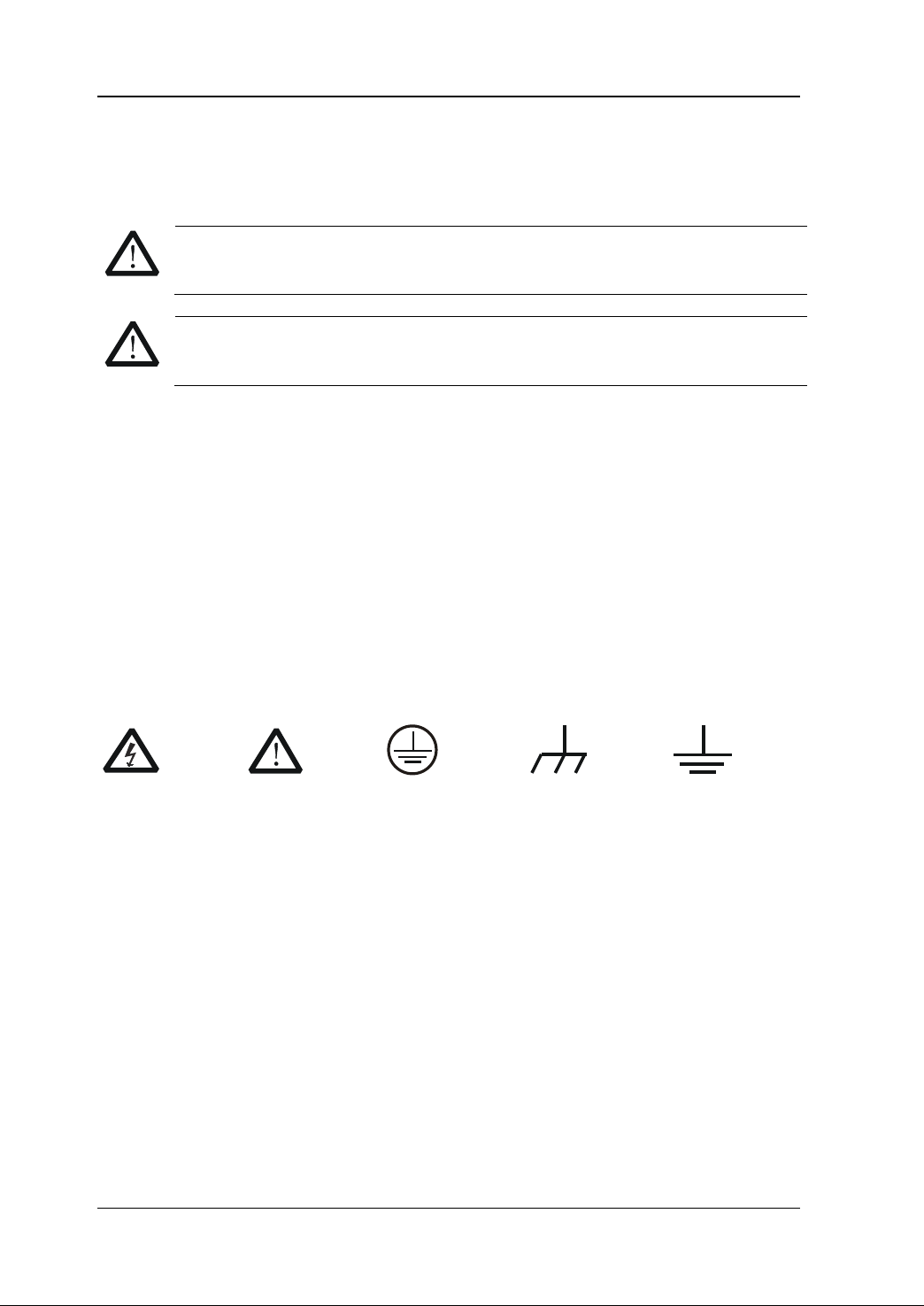
Safety Terms and Symbols
Terms Used in this Manual. These terms may appear in this manual:
Warning statements indicate conditions or practices that could result in
injury or loss of life.
Caution statements indicate conditions or practices that could result in
Terms Used on the Product. These terms may appear on the product:
result in damage to the product or other devices connected to the
Symbols Used on the Product. These symbols may appear on the product:
Voltage
Warning
Earth
Terminal
Ground
Ground
IV MSO4000/DS4000 Service Guide

RIGOL
Allgemeine Sicherheits Informationen
Überprüfen Sie diefolgenden Sicherheitshinweise
sorgfältigumPersonenschädenoderSchäden am Gerätundan damit verbundenen
weiteren Gerätenzu vermeiden. Zur Vermeidung vonGefa hren, nutze n S ie bitte das
Gerät nur so, wiein diesem Handbuchangegeben.
Um Feuer oder Verletzungen zu vermeiden, verwenden Sie ein
ordnungsgemäßes Netzkabel.
Verwenden Sie für dieses Gerät nur das für ihr Land zugelass ene u nd genehm igte
Netzkabel.
Erden des Gerätes.
Das Gerät ist durch den Schutzleiter im Netzkabel geerdet. Um Gefahren durch
elektrischen Schlag zu vermeiden, ist es unerlässlich, die Erdung durchzuführen. Erst
dann dürfen weitere Ein- oder Aus gä nge verbunden werden.
Anschluss einesTastkopfes.
Die Erdungsklemmen der Sonden sindauf dem gleichen Spannungspegel des
Instruments geerdet. SchließenSie die Erdungsklem men an keine hohe Spannung an .
Beachten Sie alle Anschlüsse.
Zur Vermeidung von Feuer oder Stromschlag, beachten Sie alle Bemerkungen und
Markierungen auf dem Instrument. Befolgen Sie die Bedienungsanleitung für weitere
Informationen, bevor Sie weitere Anschlüsse an das Instrument legen.
Verwenden Sie einen geeigneten Überspannungsschutz.
Stellen Sie sicher, daß keinerlei Überspannung (wie z.B. durch Gewitter verursacht)
das Gerät erreichen kann. Andernfallsbestehtfür den Anwender die
GefahreinesStromschlages.
Nicht ohne Abdeckung einschalten.
Betreiben Sie das Gerät nicht mit entfernten Gehäuse-Abdeckungen.
Betreiben Sie das Gerät nicht geöffnet.
Der Betrieb mit offenen oder entfernten Gehäuseteilen ist nicht zulässig. Nichts in
entsprechende Öffnungen stecken (Lüfter z.B.)
Passende Sicherung verwenden.
Setzen Sie nur die spezifikationsgemäßen Sicherungen ein.
Vermeiden Sie ungeschützte Verbindungen.
Berühren Sie keine unisolierten V erbindungen ode r Baugruppen, während das Gerät in
Betrieb ist.
MSO4000/DS4000 Service Guide V

RIGOL
Betreiben Sie d as Ge r ä t n ic h t im Fehlerfall .
Wenn Sie am Gerät einen Defekt vermuten, sorgen Sie dafür, bevor Sie das Gerät
wieder betreiben, dass eine Untersuchung durch RIGOL autorisiertem Personal
durchgeführt wird. Jedwede Wartung, Einstellarbeiten oder Austausch von Teilen am
Gerät, sowie am Zubehör dürfen nur von RIGOL autorisiert em P ersonal durch geführt
werden.
Belüftung sicherstellen.
Unzureichende Belüftung kann zu Temperaturanstiegen und somit zu thermischen
Schäden am Gerät führen. Stelle n Sie deswegen die Belüftung sicher und kontrollieren
regelmäßig Lüfter und Belüftungsöffnungen.
Nicht in feuc h te r Um g ebung betrei be n .
Zur Vermeidun g v on Kurzschluß im Geräteinneren und Stro mschla g betreiben Sie das
Gerät bitte niemals in feuchter Umgebung.
Nicht in explosiver Atmosphäre betreiben.
Zur Ve rm e idung von Pers onen- und Sachschäden ist es unumgänglich, das Gerät
ausschließlich fernab jedweder explosiven At mosphäre zu betreiben.
Geräteoberflächen sauber und trocken halten.
Um den Einfluß von Staub und Feuchtigkeit aus der Luft auszuschließen, halten Sie
bitte die Geräteoberflächen sauber und trocken.
Schutz gegen elektrostatische Entladung (ESD).
Sorgen Sie für eine elektrostatisch geschützte Umgebung, um somit Schäden und
Funktionsstörungen durch ESD zu vermeiden. Erden Sie vor dem Anschluß immer
Innen- und Außenleiter der Verbindungsleitung, um statische Aufladung zu entladen.
Die richtige Verwendung desAkku.
Wenneine Batterieverwendet wird, vermeiden Sie hohe Temperaturen bzw. Feuer
ausgesetzt werden. Bewahren Sie es außerhalbder Reichweitevon Kindern auf.
Unsachgemäße Änderung derBatte ri e (Anmerkung: Lithium-Batterie) kann zu einer
Explosion führen. VerwendenSie nur von RIGOL angegebenenAkkus.
Sicherer Transport.
Transportieren Sie das Gerät sorgfältig (Verpackung!), um Schäden an
Bedienelementen, Anschlüssen und anderen Teilen zu vermeiden.
VI MSO4000/DS4000 Service Guide
RIGOL
WARNING
Schäden oder den Tod von Personen zur Folge haben können.
CAUTION
Schäden am Gerät hervorrufen können.
DANGER
weist auf eine Verletzung ode r Gefäh r dun g hin, die sof ort
geschehen kann.
WARNING
weist auf eine Verletzung oder Gefäh rdung hin, die möglicherweise
nicht sofort geschehen.
CAUTION
weist auf eine Verletzun g ode r Gefährdung hin und bedeutet, dass
Gegenstände auftreten kann.
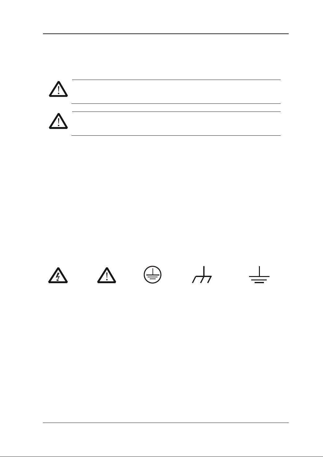
Sicherheits Begriffe und Symbole
Begriffe in diesem Guide. Diese Begriffe können in diesem Handbuch auftauchen:
Die Kennzeichnung WARNING beschreibt Gefahrenquellen die leibliche
Die Kennzeichnung Caution (Vorsicht) beschreibt Gefahrenquellen die
Begriffe auf dem Produkt. Diese Bedingungen können auf dem Produkt
erscheinen:
eine mögliche Beschädigung des Instruments oder anderer
Symbole auf dem Produkt. Diese Symbole können auf dem Produkt erscheinen:
Gefährliche
Spannung
SicherheitsHinweis
Schutz-erde Gehäusemasse Erde
MSO4000/DS4000 Service Guide VII

RIGOL
Number of
Digital
Number of
MSO4054
500MHz
4
250MHz
16
MSO4052
500MHz
2
250MHz
16
MSO4034
350MHz
4
250MHz
16
MSO4032
350MHz
2
250MHz
16
MSO4024
200MHz
4
250MHz
16
MSO4022
200MHz
2
250MHz
16
MSO4014
100MHz
4
250MHz
16
MSO4012
100MHz
2
250MHz
16
DS4054
500MHz
4
--
--
DS4052
500MHz
2
--
--
DS4034
350MHz
4
--
--
DS4032
350MHz
2
--
--
DS4024
200MHz
4
--
--
DS4022
200MHz
2
--
--
DS4014
100MHz
4
--
--
DS4012
100MHz
2
--
--
Document Overview
Format Conventions in this Manual:
1. Key
The function keys at the front panel are denoted by the format of “Button Name
(Bold) + Text Box”. For e xample, Utility denotes the “Utility” key.
2. Menu
The menu items are denoted by the format of “Menu Word (Bold) + Character
Shading”. For example, System denotes the “System” menu item under Utility.
3. Operation Step
The next step of operation is denoted by an arrow “”. For example, Utility
System denotes pressing Utility at the front panel and then pressing System.
Content Conventions in this Manual:
MSO4000/DS4000 series includes the following models.
Model
Analog
Bandwidth
Analog
Channels
Channel
Bandwidth
Digital
Channels
User Manuals of this Product:
The user manuals of this product in clude t he Quick Guide, User’s Guide, Programming
Guide, Data sheet and etc. For the latest version of the desired manual, download it
www.rigol.com.
from
VIII MSO4000/DS4000 Service Guide

Contents RIGOL
Contents
Guaranty and Declaration .......................................................................... I
Safety Requirement .................................................................................. II
General Safety Summary ............................................................................ II
Safety Terms and Symbols ......................................................................... IV
Allgemeine Sicherheits Informationen ........................................................... V
Sicherheits Begriffe und Symbole ...............................................................VII
Document Overview .............................................................................. VIII
Chapter 1 Disassemble and Assemble ................................................. 1-1
Disassemble and Assemble Notices ........................................................... 1-1
Explo ded View o f the Dev ice .................................................................... 1-2
To Disassemble the Rear Cover ................................................................. 1-4
To Disassemble the Rear Metal Cover ........................................................ 1-5
To Disassemble the Fan and Power Socket ................................................. 1-7
To Disassemble the Power Supply and Inte rface Board ................................ 1-8
To Disassemble the Front Panel and Knobs ................................................ 1-9
To Disassemble the LCD and Pinboard ..................................................... 1-11
To Disasse mble the Keyboards ................................................................ 1-12
To Disassemble the Main Board .............................................................. 1-14
Assemble Procedures ............................................................................. 1-16
Chapter 2 Troubleshooting&Maintenance ........................................... 2-1
Troubleshooting ...................................................................................... 2-1
Maintenance ........................................................................................... 2-3
System Maintenance ......................................................................... 2-3
Warranty .......................................................................................... 2-3
General Care and Cleaning ................................................................. 2-4
Environmental Considerations ............................................................ 2-4
MSO4000/DS4000 Service Guide IX

Chapter 1 Disassemble and Assemble RIGOL
1-1
WARNING
certification can disassemble the instrument.
Chapter 1 Disassemble and Assemble
Disassemble and Assemble Notices
Notices:
Do not disassemble the instrument unless for working requirement.
Only authorized personnel can disassemble the instrument.
Cut off the power supply before disassembling the instrument.
Please wear anti-static wrist strap or make other anti-static precaution when
disassembling the instrument.
Please use proper tools and follow the correct steps.
Take care not to deform the metal structure and be scuffed when disassembling
the metal structures.
Tools Required:
Phillips screwdriver T10
BNC socket
5mm hexagon socket
Make sure that the power supply is cu t off before disassembling the
instrument. Only personnel with relative traini ng or relative qualification
MSO4000/DS4000 Service Guide

RIGOL Chapter 1 Disassemble and Assemble
6
5
13
9
16
40
19
18
4
33
37
26
39
25
28
24
29
46
30
3 8
38
2
21
43
10
7
41
42
31
32
45
27
221113423 35
15
1720 1412
44
36
Exploded View of the Device
You need to get a basic understanding of the main parts of the instrument before
disassembling and assembl ing the inst rument. Whe n disasse mbling or assembling the
instrument, please follow the procedures and avoid scratching the part surface. This
manual mainly introduces the disassemble and assemble methods o f
MSO4000/DS4000 s eries digital oscillos cope. The exploded view of MSO4000/DS4000
(take MSO4000 as an example) is as shown in Figure 1-1.
Figure 1-1 Exploded View of MSO4000/DS4000
1-2 MSO4000/DS4000 Service Guide

Chapter 1 Disassemble and Assemble RIGOL
No.
Part Name
No.
Part Name
1
Front Metal Plate
24
Power PCB Board
2
Rear Metal Cover
25
Heating Tube
Handle Groove on Rear Metal
Cover
4
LCD Frame
27
Interface PCB Board
5
Navigation Knob (Inner Layer)
28
USB HOST Interface
6
Navigation Knob (Outer Layer)
29
USB DEVICE Interface
7
Rear Cover
30
LAN Interface
8
Handle
31
Video Output Interface
9
Front Panel
32
BNC Connector
PCB Board of Keys at the Right
Side of the Screen
Supporting Block of Keys at the
Top
12
Large Knob
35
Probe Pinboard
PCB Board of Keys at the Left
Side of the Screen
14
Front Non-slip P ad
37
Screen Pinboard PCB Board
15
Presser of Keys at the Top
38
Fan
16
Shield
39
Power Socket
17
Main Keys
40
LCD
Keys at the Left Side of the
Screen
Keys at the Right Side of the
Screen
20
Keys at the Top
43
Rear Support i ng Foot Block
Rear Support i ng Foot Rot ating
Shaft
Torx Pan Head Screw Asse mbly
#FW3*6
23
PCB Board of Keys at the Top
46
Blot
Table 1-1 Part Explanation of MSO4000/DS4000 Exploded View
3
26 Power Shield
10 Main Rear Supporting Leg 33
11
34 Main Key PCB Board
13 Small Knob 36
18
19
41 Auxiliary Rear Supporting Leg
42 Rear Supportin g Foot
21 Power Key 44
22 Main Board 45
The recommended disassemble procedures are as follows:
To Disassemble the Rear Cover To Disassemble the Rear Metal Cover To
Disassemble the Fan and Power Socket To Disassemble the Power Supply and
Interf ace Board T o Disa s semble the Front Panel and Knobs To Disassemble the
LCD and Pinboard T o Disassemble the Keyboa rds To Disassemble the Main Board
MSO4000/DS4000 Service Guide 1-3

RIGOL Chapter 1 Disassemble and Assemble
②
Rear Cover
To Disassemble the Rear Cover
①
①
Figure 1-2 To Disassemble the Rear Cover
Part Explanations:
① 2 screws (torx countersunk head screw #FM3*10) at the handle groove.
② 2 screws (torx pan head screw assembly #FW3*8) at the bottom of the cover (the
positions of some of the screws are not marked out in the figure above).
Disassemble Steps:
1. Remove the 2 screws (①) at the handle groove using the sc rewdriver (T10).
2. Remove the 2 screws (②, one on eac h side ) at the bottom of the cover using the
screwdriver (T10).
3. Remove the rear cover gently.
1-4 MSO4000/DS4000 Service Guide

Chapter 1 Disassemble and Assemble RIGOL
Rear Metal Cover
To Disassemble the Rear Metal Cover
①
①
①
①
Figure 1-3 To Disassemble the Rear Metal Cover
Part Explanation:
① 8 screws (torx countersunk head screw #FM3*6) fixing the front metal plate and
rear metal cover (the positions of some of the screws are not marked out in the
figure above and please disassemble them according to their actual positions).
Disassemble Steps:
1. Remove the 8 sc rews (①, 3 on the top and bottom respectively and 1 on the left
and right respectively) fixing the front metal plate and rear metal cover using the
screwdriver (T10).
2. Remove the AC power cable, rear interface board power cable and data cable
connected to the main board. Then, take off the rear metal cover gently.
MSO4000/DS4000 Service Guide 1-5

RIGOL Chapter 1 Disassemble and Assemble
Tip
assembling the rear metal cover.
Pay attention to the connecting positions of the power cables and data cable
before removing them to avoid incorrect connection or incomplete connection
when assembling the instrument.
Insert the cables to the corresponding ports on the main board before
1-6 MSO4000/DS4000 Service Guide

Chapter 1 Disassemble and Assemble RIGOL
Tip
incomplete connection when assembling the instrument.
Fan
Power Socket
To Disassemble the Fan and Power Socket
②
①
Figure 1-4 To Disassemble the Fan and Power Socket
Part Explanations:
① 2 screws (torx countersunk head screw #FM3*10) fixing the power socket.
② 4 screws (torx countersunk head self tapping screw #PTF5*10) fixing the fan.
Disassemble Steps:
1. Remove the 2 screws (①) fixing the power socket using the screwdriver (T10).
2. Remove the 4 screws (②) fixing the fan using the screwdriver (T10).
3. Remove the fan cable and the power socket cables from the corres p o nding port.
4. Remove the fan and the power socket gently.
1. When assembling the fan, pay attention to its direction.
2. Pay attention to the connecting positions of the fan cable and the power
socket cables before removing them to avoid incorrect connection or
MSO4000/DS4000 Service Guide 1-7

RIGOL Chapter 1 Disassemble and Assemble
①
Interface Board
Power Supply
②
BNC × 2
RS232
To Disassemble the Power Supply and Interface Board
①
①
①
Figure 1-5 To Disassemble the P ower Supply and Interface Board
Part Explanations:
① 4 screws (torx pan head screw #FM3*10) fixing the power supply.
② 3 screws (torx pan head screw assembly #FW3*6) fixing the rear interface board .
Disassemble Steps:
1. Remove the 2 nuts and washers at the BNC ports on the rear metal cover using
the BNC socke t.
2. Remove the British System DB9 screws on both ends of RS232 us ing the 5mm
hexagon socke t .
3. Remove the 4 screw (①) f ix ing the power supply using the screwdriver (T10).
4. Remove the 3 screws (②) fixing the rear interface board using the screwdriver
(T10).
5. Remove the power supply module and the interface board gently.
②
②
1-8 MSO4000/DS4000 Service Guide

Chapter 1 Disassemble and Assemble RIGOL
×14
Nevigation Knob
To Disassemble the Front Panel and Knobs
②
②
②
②
③
①
Figure 1-6 To Disassemble the Front Panel and Knobs
Part Explanations:
① 14 knobs (include a navigation knob).
② 6 screws (torx pan head screw assembly #FW3*8) fixing the front panel (the
positions of s ome of the sc rews a re not marked out in the figure above and please
disassemble them according to their actual positions).
③ 3 screws (torx countersunk head screw #FM3*6) fixing the front panel.
Disassemble Steps:
1. Remove the 14 knobs.
2. Remove the 6 screws (②) f ix ing the front panel using the screwdriver (T10).
3. Remove the 3 screws (③) fixing the front panel usin g the screw driver (T10) after
removing the key f ilm.
4. Remove the fr ont panel gently.
MSO4000/DS4000 Service Guide 1-9

Tip
t in unreliable paste. T her ef ore, if you only want to
you are not recommended to disassemble the front panel.
RIGOL Chapter 1 Disassemble and Assemble
It is recommended that you use a lever-like tool to pry out the knob when
disassembling the knob and place a soft pad at the force bearing point to
avoid damaging th e key film and knob.
Removing the key film would reduce the stickiness of the glue and repeated
use of the film would resul
view the main board, y o u only need to disas semble the rear metal cover and
1-10 MSO4000/DS4000 Service Guide

Chapter 1 Disassemble and Assemble RIGOL
① ① ① ②
LCD
Pinboard
To Disassemble the LCD and Pinboard
①
①
①
Figure 1-7 To Disassemble the LCD and Pinboard
Part Explanations:
① 6 screws (torx pan head screw assembly #FW3*8) fixing the LCD.
② 2 scre w s ( t orx countersunk head screw #FM3*6) fixing t he pinboard .
Disassemble Steps:
1. Remove the 6 screws (①) f ix ing the LCD using the screwdriver (T10).
2. Remove the screen line connected to the pinboard.
3. Remove the 2 screws (②) fixing the pinboard using the screwdriver (T10) and
remove the screen line connected to the main board.
MSO4000/DS4000 Service Guide 1-11

RIGOL Chapter 1 Disassemble and Assemble
②
①
① ①
Left Keyboard
Right Keyboard
Main Keyboard
Probe Pinboard
To Disassemble the Keyboards
①
①
①
①
①
Figure 1-8 To Disassemble the Keyboards
Part Explanations:
① 9 screws (torx countersunk head screw #FM3*6): 2 screws fixing the left and right
keyboards respect i ve l y a nd 5 screws fixing the main k e y board.
② 4 screws (torx pan head screw #FM3*6) fixing the probe pinboard.
Disassemble Steps:
1. Remove the 4 screws (①) fixing the left and right keyboards using the
screwdriver (T10).
2. Remove the 5 screws (①) f ix ing the main keyboard using the screwdriver (T10)
(the positions of some of the screws are not marked out in the figure above and
please disassemble them according to their actual positions).
3. Remove the 4 screws (②) fixing the probe pinboard using the screwdrive r (T10).
4. Remove the keyboard cables an d th e probe pinboard cables connected to the
main board.
1-12 MSO4000/DS4000 Service Guide

Chapter 1 Disassemble and Assemble RIGOL
Tip
before removing the m to a void in correct connectio n or incom plete
connection when assembling the instrument.
Pay attention to the connecting positions of the keyboard cables and the probe
pinboard cables
MSO4000/DS4000 Service Guide 1-13

RIGOL Chapter 1 Disassemble and Assemble
① ① ① ① ① ① ① ①
③
②
②
LA Board Retaining Clip
LA Board
To Disassemble the Main Board
1. To Disassemble the Main Board of MSO4000
①
Figure 1-9 To Disassemble the Main Boar d (MSO4000)
Part Explanation:
① 20 screws (torx pan head screw assembly #FW3*6) fixing the main board and
front metal plate.
② 2 screws (torx pan head screw assembly #FW3*6) fixing the LA board.
③ 1 screw (torx pan head screw assembly #PM/SW/FW3*10) fixing the LA
board retaining clip.
Disassemble Steps:
(1) Remove the nuts and washers (5 nuts and w ashers for f our-channel model; 3
nuts and washers for dual-channel model) at the BNC ports on the front
metal plate using the BNC socket.
(2) Remove the screw (③) f ixing the LA board retaining clip using the
screwdriver (T10), and remove the LA board retaining clip gently.
(3) Remove the 2 screws (②) fixing the LA board using the screwdriver (T10),
and remove the LA board gently.
(4) Remove the multi-station screw (#MSM 3*5.0*6.0, just below screw ② in
1-14 MSO4000/DS4000 Service Guide

Chapter 1 Disassemble and Assemble RIGOL
①
①
① ①
the blue circle in the figure above) fixing the main board and front metal
plate using the 5mm hexagon socket.
(5) Remove the 20 screws (①) fixing the main board and front metal plate using
the screwdriver (T10) (the positions of some of the screws are not marked
out in the figure above and please remove them according t o their actual
positions), and remove the main board gently.
2. To Disassemble the Main Board of DS4000
①
①
①
①
①
Figure 1-10 To Disassemble the Main Board (DS4000)
Part Explanation:
① 22 screws (torx pan head screw assembly #FW3*6) fixing the main board and
front metal plate.
Disassemble Steps:
(1) Remove the nuts and washers (5 nuts and w ashers for f our-channel model; 3
nuts and washers for dual-channel model) at the BNC ports on the front
metal plate using the BNC socket.
(2) Remove the 22 screws (①) fixing the main board and front metal plate using
the screwdriver (T10) (the positions of some of the screws are not marked
out in the figure above and please remove them according to t heir actu al
positions).
①
①
MSO4000/DS4000 Service Guide 1-15

RIGOL Chapter 1 Disassemble and Assemble
Tip
corresponding positions.
(3) Remove the main board gently.
When assembling the main board, pass the keyboard-main board cables, front
BNC-main board cable and screen line through the corresponding holes on the
front metal plate, fasten the main board and then insert the cables to the
Assemble Procedures
The assemble procedures are the reverse of the disassemble procedures. Check
whether the cables are correctly connected and whether all the screws are installed
after each step of assemble.
You are recommended to follow the order and methods introduced above
when disassembling and assembling the instrument to avoid damage to
the instrument due to improper operation and to save your time.
1-16 MSO4000/DS4000 Service Guide

Chapter 2 Troubleshooting&Maintenance RIGOL
Chapter 2 Troubleshooting&Maintenance
Troubleshooting
Some commonly encountered failures and their solutions are listed below. When you
encounter those problems, please solve them following the corresponding steps. If
the problem remains still, please contact RIGOL and provi de y ou r de vice information
(Utility System System Info).
1. The screen is still dark (no display) after pressing the power key:
(1) Check whether the power is correctly connected.
(2) Check whether the power switch is really on.
(3) Check whether the fuse is burned out. If the fuse needs to be changed,
please return the instrument to the factory and the RIGOL authorized
personnel will change the fuse for you.
(4) Restart the instrument after finishing the above inspections.
(5) If it still does not work correctly, please contact RIGOL.
2. The signal is sampled but no waveform of the signal is displayed:
(1) Check whether the probe is correctly connected to the signal connecting
wire.
(2) Check whether the signal connecting wire is correctly connected to the BNC
(namely the channel connecter).
(3) Check whether the probe is correctly connected to the item to be tested.
(4) Check whether there are signals generated from the item to be tested (you
can connect the probe compensation signal to the problematic channel to
determine which has problem, the channel or the item to be tested).
(5) Resample the signal.
3. The tested voltage amplitude is greater or lower than the ac tual value
(note that this problem usually occurs when probe is used):
Check whether the attenuation coefficient of the channel complies with the
attenuation ratio of the probe.
4. There is waveform display but not stable:
(1) Check the trigger signal source: check whether the Source item at the
trigger panel complies with the signal channel actually used.
(2) Check the trigger type: general signals should use “Edge” trigger and vid eo
signal should use “Video” trigger. Only when the proper trigger type is use d,
can the waveform be displayed stably.
(3) Check the trigger level: adjust the trigger level to the middle position of the
signal.
(4) Try to change the Coupling to “HF Reject” or “LF Reject” to filter out the
high-frequency or low-frequency noise that disturbs the trigger.
(5) Change the trigger holdoff setting.
MSO4000/DS4000 Service Guide 2-1

RIGOL Chapter 2 Troubleshooting&Maintenance
5. No display after pressing RUN/STOP:
Check whether the trigger mode in the trigger control area (TRIGGER) at the front
panel is “Normal” or “Single” and whether the trigger level exceeds the waveform
range. If yes, set the trigger level to the middle or press MODE and set the trig ger
mode to “Auto”.
Note: Using AUTO could automatically finish the above setting.
6. The waveform displayed is ladder-like:
(1) The horizontal time base might be too low. Increase the horizontal time base
to increase the horizontal resolution and improve the display.
(2) If the display Type is “Vectors”, the lines between the sample points may
cause ladder-like display. Set the display Type to “Dots” to solve the
problem.
7. Digital waveform is not stable:
(1) Check whether the s ignal input from the selected trigger source is
synchronized with the digital signal.
(2) Adjust the oscilloscope to select the appropriate trigger mode, time base and
other general settings.
(3) If the display is still not stable, please check the electrical connections and
parameter settings again.
(4) Try to use other probe (such as analog probe) to verify the signal status of
the test point.
8. Fail to connect PC or printer through USB:
(1) Check the IO Sett in g in Utility to make sure whether the setting in USB
Device matches the device currently connected.
(2) Check whether the USB cable is properly connected to the oscilloscope and
PC.
(3) Check whether the USB cable is in good condition. If necessary, r es tart the
oscilloscope.
9. The USB storage devic e cannot be recognized:
(1) Check whether the USB storage device can work normally.
(2) Make sure that the USB storage device being used is flash storage type. This
oscilloscope does not support hardware storage type.
(3) Make sur e whether the capacity of the USB storage device is too large. It is
recommended that the capacity of the USB storage device being used with
this oscilloscope is no larger than 4 GBytes.
(4) Restart the instrument and then insert the USB storage device to check it.
(5) If the USB storage device still cannot be used normally, please contact
RIGOL.
2-2 MSO4000/DS4000 Service Guide

Chapter 2 Troubleshooting&Maintenance RIGOL
Maintenance
System Maintenance
In order to ensure the performance and prolong the service life of the instrument,
please follow the recommendations below.
1. Get a full understanding of the performance and basic operating methods of the
instrument before using it.
2. In order to ensure the measurement accuracy and the service life of the
instrument, the instrument should be used and stored in places away from dust,
shock, moisture, magnetic field and static; besides, the instrument should be
placed in places where it will not be exposed to sunlight for long periods of time.
3. Do not operate t he instrument when failure occurs. In this situation, you need to
first solve the failure. Besides, regula r test and calibration shoul d be pe rformed to
ensure the accuracy of the performance.
4. Arrange the instrument properly after you finish the operation of the instrument.
5. Keep the relative accessories of the instrument properly for future use.
Warranty
RIGOL warrants that its products m ainframe and accessories will be free from
defects in materials and workmanship within the warranty period.
If a product is proven to be defective within the respective period, RIGOL guarantees
the free repl acement or re pair of p roduct s which a re app rove d defe ctive. To get repair
service, please contact with your nearest RIGOL sales and service office.
RIGOL does not provide other warranty items except the one being provided by this
warranty statement. The warranty items include but not being subjected to the hint
guarantee items related to tradable char acteristic and an y partic ular purpose. RIGOL
will not take any responsibility in cases regarding to indirect, particular and ensuing
damage.
MSO4000/DS4000 Service Guide 2-3

RIGOL Chapter 2 Troubleshooting&Maintenance
CAUTION
WARNING
completely dry before reconnecting to a power source.
General Care and Cleaning
General Care
Do not store or leave the instrument where it may be exposed to direct sunlight for
long periods of time.
Cleaning
Clean the instrument regularly according to its operating conditions. To clean the
exterior surface, perform the following steps:
1. Disconnect the instrument from all power sources.
2. Clean the loose dust on the outside of the i nstrument with a lint -free cloth (with a
mild detergent or water). When cleaning the LCD, take care to avoid scarifying it.
To avoid damage to the instrument, do not expose it to caustic liquids.
To avoid injury resulting from short circuit, make sure the instrument is
Environmental Considerations
The following symbol indicates that this product complies with the WEEE Directive
2002/96/EC.
Product End-of-Life Handling
The equipment may contain substances that could be harmful to the environment or
human health. In order to avoid the release of such substances into the environment
and harm to human health, we encourage you to recycle this product in an
appropriate system that will ensure that most of the materials are reused or recycled
appropriately. Please contact your local authorities for disposal or recycling
information.
2-4 MSO4000/DS4000 Service Guide
 Loading...