


RIGOL
Programming Guide
MSO1000Z/DS1000Z Series
Digital Oscilloscope
Dec. 2015
RIGOL TECHNOLOGIES, INC.


RIGOL
Guaranty and Declaration
Copyright
© 2014 RIGOL TECHNOLOGIES, INC. All Rights Reserved.
Trademark Information
RIGOL is a registered trademark of RIGOL TECHNOLOGIES, INC.
Publication Number
PGA19108-1110
Software Version
00.04.03.SP2
Software upgrade might change or add product features. Please acquire the latest version of the manual
from RIGOL website or contact RIGOL to upgrade the software.
Notices
RIGOL products are covered by P.R.C. and foreign patents, issued and pending.
RIGOL reserves the right to modify or change parts of or all the specifications and pricing policies at
the company’s sole decision.
Information in this publication replaces all previously released materials.
Information in this publication is subject to change without notice.
RIGOL shall not be liable for either incidental or consequential losses in connection with the furnishing,
use, or performance of this manual, as well as any information contained.
Any part of this document is forbidden to be copied, photocopied, or rearranged without prior written
approval of RIGOL.
Product Certification
RIGOL guarantees that this product conforms to the national and industrial standards in China as well as
the ISO9001:2008 standard and the ISO14001: 2004 standard. Other international standard conformance
certifications are in progress.
Contact Us
If you have any problem or requirement when using our products or this manual, pleas e contact RIGOL.
E-mail: service@rigol.com
Website: www.rigol.com
MSO1000Z/DS1000Z Programming Guide I

RIGOL
Tip
RIGOL
Number of
Channels
Number of
Channels
MSO1104Z-S
100 MHz
4 2 16
MSO1074Z-S
70 MHz
4 2 16
MSO1104Z
100 MHz
4
--
16
MSO1074Z
70 MHz
4
--
16
DS1104Z-S Plus
100 MHz
4 2 16
[1]
DS1074Z-S Plus
70 MHz
4 2 16
[1]
DS1104Z Plus
100 MHz
4
--
16
[1]
DS1074Z Plus
70 MHz
4
--
16
[1]
DS1054Z
50 MHz
4
--
--
Document Overview
This manual provides guidance on how to use the SC PI commands in programming to realize remote
control of RIGOL MSO1000Z/DS1000Z series digital oscilloscope through the remote interface.
MSO1000Z/DS1000Z can communicate with a PC through the USB or the LAN bus.
Main Topics in this Manual:
Chapter 1 Programming Overview
This chapter introduces how to build the remote communication between MSO1000Z/DS1000Z series
digital oscilloscope and the PC. It also introduces the remote control methods as well as the syntax,
symbols, parameters and abbreviation rules of the SCPI commands.
Chapter 2 Command System
This chapter introduces the syntax, function, parameter and us ing instruction of each command.
Chapter 3 Programming Demos
This chapter lists some programming demos to illustrate how to use comm ands to realize the common
functions of the oscilloscope in the development environments of Excel, Matlab, LabVIEW, Visual Basic 6.0
and Visual C++ 6.0.
For the newest version of this manual, please download it from
official website (www.rigol.com).
Format Conventions in this Manual:
1. Key
The function key at the front panel is denoted by the format of "Key Name (Bold) + Text Box" in the
manual. For example, Utility denotes the "Utility" key at the front panel.
2. Menu
The menu item is denoted by the format of "Menu Word (Bold) + Character Shading" in the manual.
For example, System denotes the "System" item under Utility.
3. Operation Step
The next step of the operation is denoted by an arrow "" in the manual. For example, Utility
System denotes pressing Utility at the front panel and then pressing System.
Content Conventions in this Manual:
MSO1000Z/DS1000Z series includes the following models. Unless otherwise noted, this manual takes
MSO1104Z-S as an example to illustrate the command system of MSO1000Z/DS1000Z series.
Model Analog Bandwidth
Analog
Signal Source
Number of
Digital Channels
[1]
Note
II MSO1000Z/DS1000Z Programming Guide
: Need to be upgraded to MSO using the MSO upgrade option.

Contents RIGOL
Contents
Guaranty and Declaration ......................................................................................................... I
Document Overview ................................................................................................................. II
Chapter 1 Programming Overview...................................................................................... 1-1
To Build Remote Communication ............................................................................................... 1-2
Remote Control Methods ........................................................................................................... 1-4
SCPI Command Overview .......................................................................................................... 1-5
Syntax ............................................................................................................................... 1-5
Symbol Description ............................................................................................................ 1-5
Parameter Type .................................................................................................................. 1-5
Command Abbreviation ...................................................................................................... 1-6
Chapter 2 Command System ............................................................................................... 2-1
:AUToscale ............................................................................................................................... 2-2
:CLEar...................................................................................................................................... 2-2
:RUN ........................................................................................................................................ 2-2
:STOP ...................................................................................................................................... 2-2
:SINGle .................................................................................................................................... 2-3
:TFORce ................................................................................................................................... 2-3
:ACQuire Commands ................................................................................................................. 2-4
:ACQuire:AVERages ............................................................................................................ 2-4
:ACQuire:MDEPth ............................................................................................................... 2-5
:ACQuire:TYPE ................................................................................................................... 2-6
:ACQuire:SRATe? ................................................................................................................ 2-7
:CALibrate Commands ............................................................................................................... 2-8
:CALibrate:QUIT ................................................................................................................ 2-8
:CALibrate:STARt ............................................................................................................... 2-8
:CHANnel<n> Commands ......................................................................................................... 2-9
:CHANnel<n>:BWLimit ....................................................................................................... 2-9
:CHANnel<n>:COUPling ................................................................................................... 2-10
:CHANnel<n>:DISPlay ..................................................................................................... 2-10
:CHANnel<n>:INVert ....................................................................................................... 2-11
:CHANnel<n>:OFFSet ...................................................................................................... 2-11
:CHANnel<n>:RANGe ...................................................................................................... 2-12
:CHANnel<n>:TCAL ......................................................................................................... 2-13
:CHANnel<n>:SCALe ....................................................................................................... 2-14
:CHANnel<n>:PROBe ....................................................................................................... 2-14
:CHANnel<n>:UNITs ........................................................................................................ 2-15
:CHANnel<n>:VERNier ..................................................................................................... 2-15
:CURSor Commands ............................................................................................................... 2-16
:CURSor:MODE ................................................................................................................ 2-16
:CURSor:MANual .............................................................................................................. 2-17
:CURSor:TRACk ............................................................................................................... 2-24
:CURSor:AUTO ................................................................................................................. 2-29
:CURSor:XY ..................................................................................................................... 2-33
:DECoder Commands .............................................................................................................. 2-37
:DECoder<n>:MODE ........................................................................................................ 2-37
:DECoder<n>:DISPlay ..................................................................................................... 2-38
:DECoder<n>:FORMat ..................................................................................................... 2-38
:DECoder<n>:POSition .................................................................................................... 2-39
:DECoder<n>:THREshold:CHANnel1 ................................................................................. 2-40
:DECoder<n>:THREshold:CHANnel2 ................................................................................. 2-40
:DECoder<n>:THREshold:CHANnel3 ................................................................................. 2-40
:DECoder<n>:THREshold:CHANnel4 ................................................................................. 2-40
:DECoder<n>:THREshold:AUTO ....................................................................................... 2-41
:DECoder<n>:CONFig:LABel ............................................................................................. 2-41
MSO1000Z/DS1000Z Programming Guide III

RIGOL Contents
:DECoder<n>:CONFig:LINE .............................................................................................. 2-42
:DECoder<n>:CONFig:FORMat.......................................................................................... 2-42
:DECoder<n>:CONFig:ENDian .......................................................................................... 2-43
:DECoder<n>:CONFig:WIDth ............................................................................................ 2-43
:DECoder<n>:CONFig:SRATe? .......................................................................................... 2-43
:DECoder<n>:UART (Option) ............................................................................................ 2-44
:DECoder<n>:IIC (Option) ............................................................................................... 2-48
:DECoder<n>:SPI (Option) ............................................................................................... 2-50
:DECoder<n>:PARallel ...................................................................................................... 2-56
:DISPlay Commands ................................................................................................................ 2-62
:DISPlay:CLEar ................................................................................................................. 2-62
:DISPlay:DATA? ................................................................................................................ 2-63
:DISPlay:TYPE .................................................................................................................. 2-64
:DISPlay:GRADing:TIME ................................................................................................... 2-65
:DISPlay:WBRightness ...................................................................................................... 2-65
:DISPlay:GRID ................................................................................................................. 2-66
:DISPlay:GBRightness ....................................................................................................... 2-66
:ETABle Commands ................................................................................................................. 2-67
:ETABle<n>:DISP ............................................................................................................. 2-67
:ETABle<n>:FORMat ........................................................................................................ 2-67
:ETABle<n>:VIEW ............................................................................................................ 2-68
:ETABle<n>:COLumn ....................................................................................................... 2-68
:ETABle<n>:ROW ............................................................................................................ 2-69
:ETABle<n>:SORT ............................................................................................................ 2-69
:ETABle<n>:DATA? .......................................................................................................... 2-70
:FUNCtion Commands (Option) ................................................................................................ 2-71
:FUNCtion:WRECord:FEND ................................................................................................ 2-71
:FUNCtion:WRECord:FMAX? .............................................................................................. 2-72
:FUNCtion:WRECord:FINTerval .......................................................................................... 2-72
:FUNCtion:WRECord:PROMpt ............................................................................................ 2-72
:FUNCtion:WRECord:OPERate ........................................................................................... 2-73
:FUNCtion:WRECord:ENABle ............................................................................................. 2-73
:FUNCtion:WREPlay:FSTart ................................................................................................ 2-74
:FUNCtion:WREPlay:FEND ................................................................................................. 2-75
:FUNCtion:WREPlay:FMAX? ............................................................................................... 2-75
:FUNCtion:WREPlay:FINTerval ........................................................................................... 2-76
:FUNCtion:WREPlay:MODE ................................................................................................ 2-76
:FUNCtion:WREPlay:DIRection .......................................................................................... 2-77
:FUNCtion:WREPlay:OPERate ............................................................................................ 2-77
:FUNCtion:WREPlay:FCURrent ........................................................................................... 2-78
IEEE488.2 Common Commands ............................................................................................... 2-79
*CLS ................................................................................................................................ 2-79
*ESE ................................................................................................................................ 2-79
*ESR? .............................................................................................................................. 2-80
*IDN? .............................................................................................................................. 2-80
*OPC ............................................................................................................................... 2-80
*RST ............................................................................................................................... 2-80
*SRE ............................................................................................................................... 2-81
*STB? .............................................................................................................................. 2-81
*TST? .............................................................................................................................. 2-81
*WAI ............................................................................................................................... 2-81
:LA Commands ....................................................................................................................... 2-82
:LA:ACTive ....................................................................................................................... 2-82
:LA:AUTosort .................................................................................................................... 2-83
:LA:DIGital<n>:DISPlay .................................................................................................... 2-83
:LA:DIGital<n>:POSition ................................................................................................... 2-84
:LA:DIGital<n>:LABel ....................................................................................................... 2-84
:LA:DISPlay ...................................................................................................................... 2-85
IV MSO1000Z/DS1000Z Programming Guide

Contents RIGOL
:LA:POD<n>:DISPlay ....................................................................................................... 2-86
:LA:POD<n>:THReshold ................................................................................................... 2-86
:LA:SIZE .......................................................................................................................... 2-87
:LA:STATe ........................................................................................................................ 2-87
:LA:TCALibrate ................................................................................................................. 2-88
:MATH Commands .................................................................................................................. 2-89
:MATH:DISPlay ................................................................................................................ 2-90
:MATH:OPERator .............................................................................................................. 2-90
:MATH:SOURce1 .............................................................................................................. 2-91
:MATH:SOURce2 .............................................................................................................. 2-92
:MATH:LSOUrce1 ............................................................................................................. 2-92
:MATH:LSOUrce2 ............................................................................................................. 2-93
:MATH:SCALe .................................................................................................................. 2-93
:MATH:OFFSet ................................................................................................................. 2-94
:MATH:INVert .................................................................................................................. 2-94
:MATH:RESet ................................................................................................................... 2-95
:MATH:FFT:SOURce.......................................................................................................... 2-95
:MATH:FFT:WINDow ........................................................................................................ 2-95
:MATH:FFT:SPLit .............................................................................................................. 2-96
:MATH:FFT:UNIT .............................................................................................................. 2-96
:MATH:FFT:HSCale ........................................................................................................... 2-97
:MATH:FFT:HCENter ......................................................................................................... 2-98
:MATH:FFT:MODE ............................................................................................................ 2-98
:MATH:FILTer:TYPE .......................................................................................................... 2-99
:MATH:FILTer:W1 ........................................................................................................... 2-100
:MATH:FILTer:W2 ........................................................................................................... 2-101
:MATH:OPTion:STARt ..................................................................................................... 2-101
:MATH:OPTion:END........................................................................................................ 2-102
:MATH:OPTion:INVert .................................................................................................... 2-102
:MATH:OPTion:SENSitivity .............................................................................................. 2-103
:MATH:OPTion:DIStance ................................................................................................ 2-103
:MATH:OPTion:ASCale .................................................................................................... 2-104
:MATH:OPTion:THReshold1 ............................................................................................ 2-104
:MATH:OPTion:THReshold2 ............................................................................................ 2-105
:MATH:OPTion:FX:SOURce1 ........................................................................................... 2-105
:MATH:OPTion:FX:SOURce2 ........................................................................................... 2-106
:MATH:OPTion:FX:OPERator ........................................................................................... 2-106
:MASK Commands ................................................................................................................ 2-107
:MASK:ENABle ............................................................................................................... 2-107
:MASK:SOURce .............................................................................................................. 2-108
:MASK:OPERate ............................................................................................................. 2-108
:MASK:MDISplay ............................................................................................................ 2-109
:MASK:SOOutput ........................................................................................................... 2-109
:MASK:OUTPut............................................................................................................... 2-110
:MASK:X ........................................................................................................................ 2-110
:MASK:Y ........................................................................................................................ 2-110
:MASK:CREate ............................................................................................................... 2-111
:MASK:PASSed? ............................................................................................................. 2-111
:MASK:FAILed? .............................................................................................................. 2-111
:MASK:TOTal? ................................................................................................................ 2-111
:MASK:RESet ................................................................................................................. 2-111
:MEASure Commands ............................................................................................................ 2-112
:MEASure:SOURce ......................................................................................................... 2-116
:MEASure:COUNter:SOURce ........................................................................................... 2-116
:MEASure:COUNter:VALue? ............................................................................................ 2-117
:MEASure:CLEar ............................................................................................................. 2-117
:MEASure:RECover ......................................................................................................... 2-117
:MEASure:ADISplay ........................................................................................................ 2-118
MSO1000Z/DS1000Z Programming Guide V

RIGOL Contents
:MEASure:AMSource ....................................................................................................... 2-118
:MEASure:SETup:MAX ..................................................................................................... 2-119
:MEASure:SETup:MID ..................................................................................................... 2-119
:MEASure:SETup:MIN ..................................................................................................... 2-120
:MEASure:SETup:PSA ...................................................................................................... 2-120
:MEASure:SETup:PSB ...................................................................................................... 2-121
:MEASure:SETup:DSA ..................................................................................................... 2-121
:MEASure:SETup:DSB ..................................................................................................... 2-122
:MEASure:STATistic:DISPlay ............................................................................................ 2-122
:MEASure:STATistic:MODE .............................................................................................. 2-123
:MEASure:STATistic:RESet ............................................................................................... 2-123
:MEASure:STATistic:ITEM ................................................................................................ 2-124
:MEASure:ITEM .............................................................................................................. 2-125
:REFerence Commands .......................................................................................................... 2-126
:REFerence:DISPlay ........................................................................................................ 2-126
:REFerence<n>:ENABle .................................................................................................. 2-126
:REFerence<n>:SOURce ................................................................................................. 2-127
:REFerence<n>:VSCale .................................................................................................. 2-127
:REFerence<n>:VOFFset ................................................................................................ 2-128
:REFerence<n>:RESet .................................................................................................... 2-128
:REFerence<n>:CURRent ............................................................................................... 2-128
:REFerence<n>:SAVe ..................................................................................................... 2-129
:REFerence<n>:COLor ................................................................................................... 2-129
[:SOURce[<n>]] Commands ................................................................................................. 2-130
[:SOURce[<n>]]:OUTPut[<n>][:STATe] .......................................................................... 2-131
[:SOURce[<n>]]:OUTPut[<n>]:IMPedance ..................................................................... 2-131
[:SOURce[<n>]]:FREQuency[:FIXed] .............................................................................. 2-132
[:SOURce[<n>]]:PHASe[:ADJust] .................................................................................... 2-132
[:SOURce[<n>]]:PHASe:INITiate .................................................................................... 2-133
[:SOURce[<n>]]:FUNCtion[:SHAPe] ................................................................................ 2-133
[:SOURce[<n>]]:FUNCtion:RAMP:SYMMetry .................................................................... 2-134
[:SOURce[<n>]]:VOLTage[:LEVel][:IMMediate][:AMPLitude] ............................................. 2-134
[:SOURce[<n>]]:VOLTage[:LEVel][:IMMediate]:OFFSet .................................................... 2-135
[:SOURce[<n>]]:PULSe:DCYCle ...................................................................................... 2-135
[:SOURce[<n>]]:MOD[:STATe] ....................................................................................... 2-136
[:SOURce[<n>]]:MOD:TYPe ........................................................................................... 2-136
[:SOURce[<n>]]:MOD:AM[:DEPTh] ................................................................................. 2-137
[:SOURce[<n>]]:MOD:AM:INTernal:FREQuency ............................................................... 2-137
[:SOURce[<n>]]:MOD:FM:INTernal:FREQuency ............................................................... 2-137
[:SOURce[<n>]]:MOD:AM:INTernal:FUNCtion .................................................................. 2-138
[:SOURce[<n>]]:MOD:FM:INTernal:FUNCtion .................................................................. 2-138
[:SOURce[<n>]]:MOD:FM[:DEVIation] ............................................................................ 2-139
[:SOURce[<n>]]:APPLy? ................................................................................................. 2-139
[:SOURce[<n>]]:APPLy:NOISe ........................................................................................ 2-140
[:SOURce[<n>]]:APPLy:PULSe ........................................................................................ 2-140
[:SOURce[<n>]]:APPLy:RAMP ......................................................................................... 2-140
[:SOURce[<n>]]:APPLy:SINusoid .................................................................................... 2-140
[:SOURce[<n>]]:APPLy:SQUare ...................................................................................... 2-140
[:SOURce[<n>]]:APPLy:USER ......................................................................................... 2-140
:STORage Commands ............................................................................................................ 2-142
:STORage:IMAGe:TYPE ................................................................................................... 2-142
:STORage:IMAGe:INVERT ............................................................................................... 2-142
:STORage:IMAGe:COLor ................................................................................................. 2-143
:SYSTem Commands ............................................................................................................. 2-144
:SYSTem:AUToscale ........................................................................................................ 2-144
:SYSTem:BEEPer ............................................................................................................ 2-145
:SYSTem:ERRor[:NEXT]? ................................................................................................. 2-145
:SYSTem:GAM? .............................................................................................................. 2-145
VI MSO1000Z/DS1000Z Programming Guide

Contents RIGOL
:SYSTem:LANGuage ....................................................................................................... 2-145
:SYSTem:LOCKed ........................................................................................................... 2-146
:SYSTem:PON ................................................................................................................ 2-146
:SYSTem:OPTion:INSTall ................................................................................................ 2-146
:SYSTem:OPTion:UNINSTall ............................................................................................ 2-147
:SYSTem:RAM? .............................................................................................................. 2-147
:SYSTem:SETup ............................................................................................................. 2-147
[:TRACe[<n>]] Commands ................................................................................................... 2-148
[:TRACe[<n>]]:DATA ..................................................................................................... 2-148
[:TRACe[<n>]]:DATA:DAC16 .......................................................................................... 2-149
[:TRACe[<n>]]:DATA:DAC ............................................................................................. 2-150
[:TRACe[<n>]]:DATA:POINts ......................................................................................... 2-151
[:TRACe[<n>]]:DATA:POINts:INTerpolate ....................................................................... 2-151
[:TRACe[<n>]]:DATA:VALue .......................................................................................... 2-152
[:TRACe[<n>]]:DATA:LOAD? .......................................................................................... 2-152
:TIMebase Commands .......................................................................................................... 2-153
:TIMebase:DELay:ENABle ............................................................................................... 2-153
:TIMebase:DELay:OFFSet ............................................................................................... 2-154
:TIMebase:DELay:SCALe ................................................................................................ 2-155
:TIMebase[:MAIN]:OFFSet.............................................................................................. 2-156
:TIMebase[:MAIN]:SCALe ............................................................................................... 2-157
:TIMebase:MODE ........................................................................................................... 2-157
:TRIGger Commands ............................................................................................................ 2-158
:TRIGger:MODE ............................................................................................................. 2-158
:TRIGger:COUPling ........................................................................................................ 2-159
:TRIGger:STATus? .......................................................................................................... 2-159
:TRIGger:SWEep ............................................................................................................ 2-159
:TRIGger:HOLDoff ......................................................................................................... 2-160
:TRIGger:NREJect .......................................................................................................... 2-160
:TRIGger:POSition? ........................................................................................................ 2-161
:TRIGger:EDGe .............................................................................................................. 2-162
:TRIGger:PULSe ............................................................................................................. 2-164
:TRIGger:SLOPe ............................................................................................................. 2-168
:TRIGger:VIDeo ............................................................................................................. 2-173
:TRIGger:PATTern .......................................................................................................... 2-176
:TRIGger:DURATion ....................................................................................................... 2-179
:TRIGger:TIMeout (Option) ............................................................................................ 2-183
:TRIGger:RUNT (Option) ................................................................................................ 2-185
:TRIGger:WINDows (Option) .......................................................................................... 2-189
:TRIGger:DELay (Option) ............................................................................................... 2-192
:TRIGger:SHOLd (Option) ............................................................................................... 2-196
:TRIGger:NEDGe (Option) .............................................................................................. 2-199
:TRIGger:RS232 (Option) ............................................................................................... 2-201
:TRIGger:IIC (Option) .................................................................................................... 2-206
:TRIGger:SPI (Option) .................................................................................................... 2-210
:WAVeform Commands ......................................................................................................... 2-216
:WAVeform:SOURce ....................................................................................................... 2-217
:WAVeform:MODE .......................................................................................................... 2-218
:WAVeform:FORMat ....................................................................................................... 2-218
:WAVeform:DATA?.......................................................................................................... 2-219
:WAVeform:XINCrement? ............................................................................................... 2-222
:WAVeform:XORigin? ...................................................................................................... 2-222
:WAVeform:XREFerence? ................................................................................................ 2-223
:WAVeform:YINCrement? ............................................................................................... 2-223
:WAVeform:YORigin? ...................................................................................................... 2-223
:WAVeform:YREFerence? ................................................................................................ 2-224
:WAVeform:STARt .......................................................................................................... 2-224
:WAVeform:STOP ........................................................................................................... 2-225
MSO1000Z/DS1000Z Programming Guide VII

RIGOL Contents
:WAVeform:PREamble? ................................................................................................... 2-226
Chapter 3 Programming Demos ......................................................................................... 3-1
Programming Preparations ......................................................................................................... 3-2
Excel Programming Demo .......................................................................................................... 3-3
Matlab Programming Demo........................................................................................................ 3-7
LabVIEW Programming Demo .................................................................................................... 3-9
Visual Basic Programming Demo .............................................................................................. 3-13
Visual C++ Programming Demo ............................................................................................... 3-15
VIII MSO1000Z/DS1000Z Programming Guide

Chapter 1 Programming Overview RIGOL
Chapter 1 Programming Overview
This chapter introduces how to build the remote communication between MSO1000Z/DS1000Z series
digital oscilloscope and the PC. It also introduces the remote control methods as well as the syntax,
symbols, parameters and abbreviation rules of the SCPI commands.
Main topics of this chapter:
To Build Remote Communication
Remote Control Methods
SCPI Command Overview
MSO1000Z/DS1000Z Programming Guide 1-1
RIGOL Chapter 1 Programming Overview
1
2
To Build Remote Communication
This oscilloscope can communicate with a PC through the USB or the LAN bus. This section introduces how
to control the oscilloscope remotely through the USB interface using Ultra Sigma in details.
Operation Steps:
1. Install the Ultra Sigma common PC software
Download the Ultra Sigma common PC software from RIGOL official website (
install it according to the instructions.
2. Connect the instrument and PC and configure the interface parameters of the instrument
MSO1000Z/DS1000Z can communicate with a PC through the USB or the LAN bus. This manual takes
the USB interface as an example.
(1) Connect the devices
Connect the USB Device interface at the real pan el of th e osc illoscope and the USB H ost in terf ace
of the PC using a USB ca bl e .
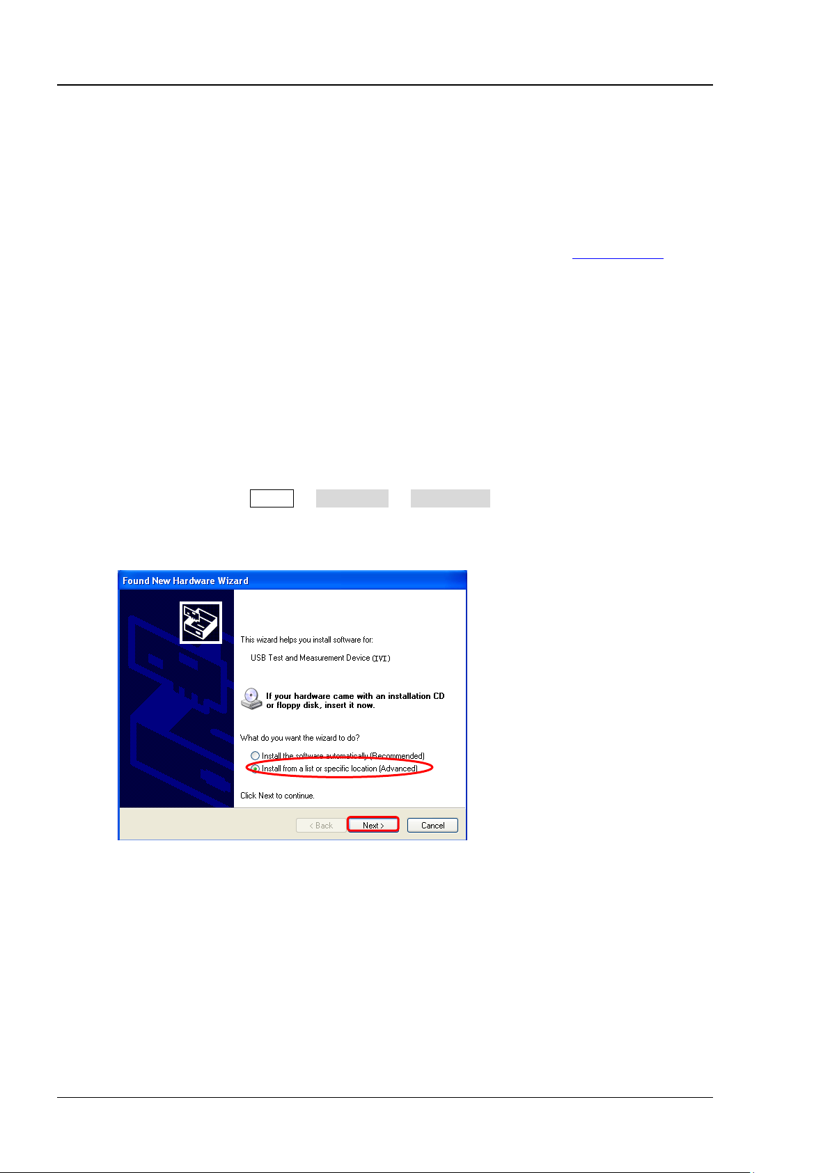
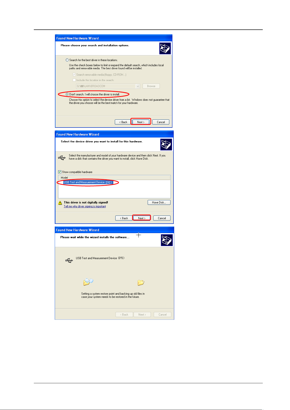
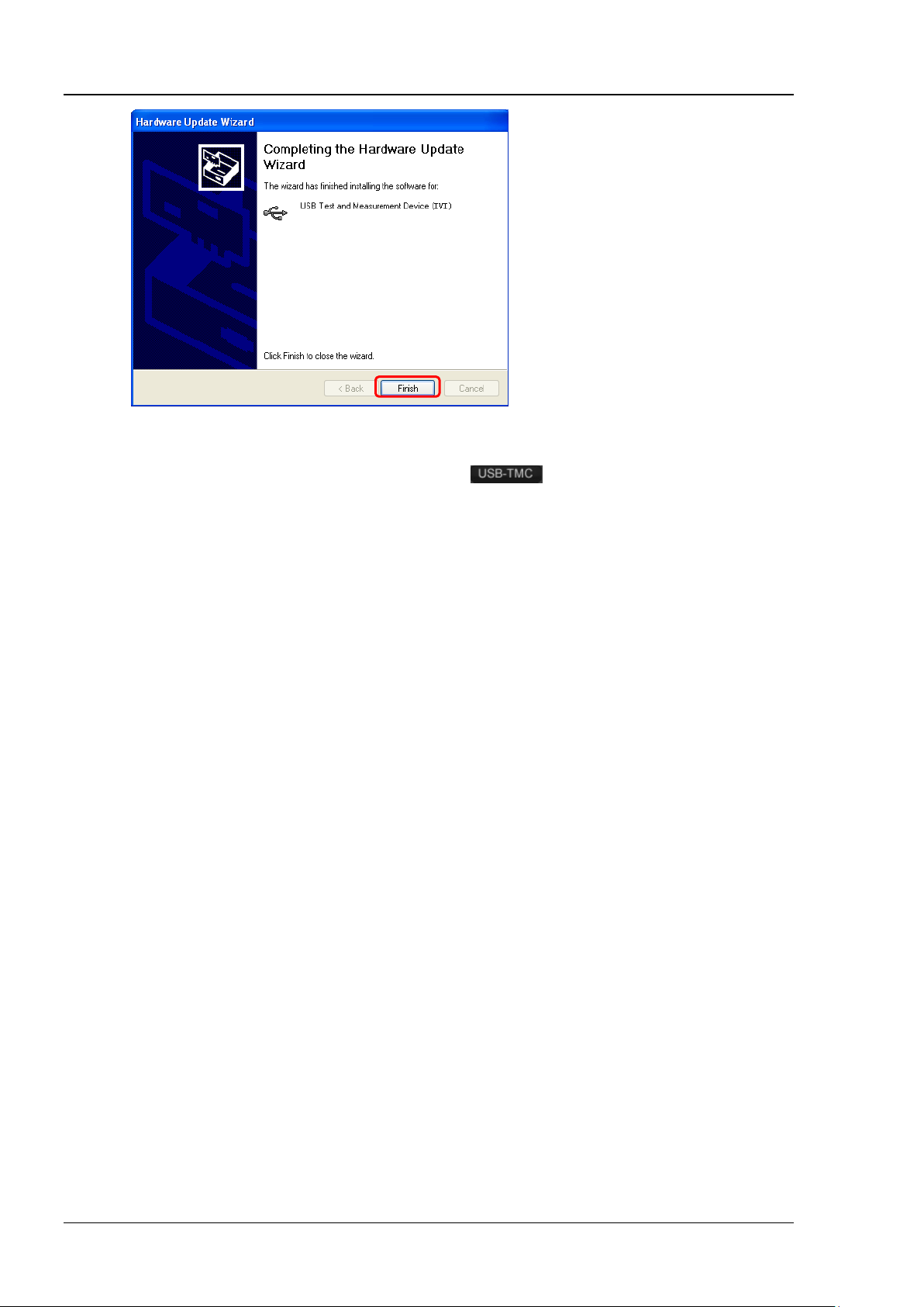
(2) Install the USB driver
This oscilloscope is a USB-TMC device. After you connect the oscilloscope to the PC and turn both
on for the first time (the oscilloscope is automatically configured to the USB interface; at the same
time, make sure that Utility IO Setting USB Device is set to "Computer"), the Found
New Hardware Wizard as shown in the figure below is displayed on the PC. Please install the
"USB Test and Measurement D evice (IVI)" driver following the directions in the wizard. The steps
are as follows.
www.rigol.com) and
1-2 MSO1000Z/DS1000Z Programming Guide
Chapter 1 Programming Overview RIGOL
3 4 5
6
MSO1000Z/DS1000Z Programming Guide 1-3
RIGOL Chapter 1 Programming Overview
7
(3) Search for device resource
Start up the Ultra Sigma and the software will automatically search for the instrument resources
currently connected to the PC. You can also click
(4) View the device res o ur ces
The resources found will appear under the "RIGOL Online Resource" directory and the model
number and USB interface information of the instrument will also be displayed.
For example, MSO1104Z (USB0::0x1AB1::0x04CE::DS1ZD170800001::INSTR).
(5) Control the instrument remotely
Right click the resource name "MSO1104Z (USB0::0x1AB1::0x04CE::DS1ZD170800001::INSTR)"
and select "SCPI Panel Control" to turn on the remote command control panel through which you
can send commands and read data.
to search for the resources.
Remote Control Methods
1. User-defined Programming
Users can use SCPI (Standard Commands for Programmable Instruments) commands to program and
control the oscilloscope. For details, refer to the introductions in "Chapter 3 Programming Demos".
2. Send SCPI Commands via PC Software
You can control the oscilloscope remotely by sending SCPI commands via PC software. Ultra Sigma
provided by RIGOL is recommended
.
1-4 MSO1000Z/DS1000Z Programming Guide

Chapter 1 Programming Overview RIGOL
SCPI Command Overview
SCPI (Standard Comm ands for Programmable Instruments) is a standardized instrument programming
language that is built upon the standard IEEE 488.1 and IEEE 488.2 and conforms to various standards
(such as the float ing point operation rule in IEEE 754 standard, ISO 646 7-bit coded character for
information intercha nge (equivalent to ASCII programming)). The SCPI commands provide a hierarchical
tree structure and consist of multiple subsystems. Each com mand subsystem consists of a root keyword
and one or more sub-keywords.
Syntax
The command string usually starts with ":"; the keywords are separated by ":" and are followed by the
parameter settings available; "?" is added at the end of the command string to indicate query; the
command keywords and the first parameter are separated by space.
For example,
:ACQuire:TYPE <type>
:ACQuire:TYPE?
ACQuire is the root keyword of the command. TYPE is the second-level keyword. The command string starts
with ":" which is also used t o separate the multiple-level keywords. <type> represents the parameters
available for setting. "?" represents query. The command keywords :ACQuire:TYPE and parameter <type>
are separated by a space.
"," is generally used for separating multiple parameters contained in the same command, for example,
[:TRACe[<n>]]:DATA:VALue volatile,<points>,<data>
Symbol Description
The following symbols will not be sent with the commands.
1. Braces {}
The parameters enclosed in the braces are optional and are usually separated by the vertical bar "|".
When using the command, one of the parameters must be selected.
2. Vertical Bar |
The vertical bar is used to separate multiple parameters and one of the parameters must be selected
when using the command.
3. Square Brackets []
The content in the square brackets can be omitted.
4. Triangle Brackets <>
The parameter enclosed in the triangle brackets must be replaced by an effective value.
Parameter Type
1. Bool
The parameter could be ON, OFF, 1, or 0. For example,
:MEASure:ADISplay <bool >
:MEASure:ADISplay?
Wherein,
<bool> can be set to {{1|ON}|{0|OFF}}.
MSO1000Z/DS1000Z Programming Guide 1-5

RIGOL Chapter 1 Programming Overview
The query returns 1 or 0.
2. Discrete
The parameter could be any of the values listed. For example,
:ACQuire:TYPE <type>
:ACQuire:TYPE?
Wherein,
<type> can be set to NORMal|AVERages|PEAK|HRESolution.
The query returns the abbreviations (NORM, AVER, PEAK, or HRES).
3. Integer
Unless otherwise noted, the parameter can be any integer (NR1 format) within the effective value
range. Note that do not set the parameter to a decimal, otherwise errors will occur. For example,
:DISPlay:GBRightne ss <br i ghtne ss >
:DISPlay:GBRightness?
Wherein,
<brightness> can be set to any integer between 0 and 100.
The query returns an integer between 0 and 100.
4. Real
The parameter can be any real number within the effective value range and this command accepts
decimal (NR2 format) and scientific notation (NR3 format) parameter input. For example,
:TRIGger:TIMeout:TIMe <NR3>
:TRIGger:TIMeout:TIMe?
Wherein,
<NR3> can be set to any real number between 1.6e-08 (namely 16ns) to 1e+01 (namely 10s).
The query returns a real number in scientific notation.
5. ASCII String
The parameter should be the combinations of ASCII characters.
For example,
:SYSTem:OPTion:INSTall <license>
Wherein,
<license> can be set to PDUY9N9QTS9PQSWPLAETRD3UJHYA.
Command Abbreviation
All the commands are case-insensitive and you can use any of them. If abbreviation is used, all the capital
letters in the command must be written completely. For example,
:MEASure:ADISplay? can be abbreviated to :MEAS:ADIS?.
1-6 MSO1000Z/DS1000Z Programming Guide

Chapter 2 Command System RIGOL
Chapter 2 Command System
This chapter introduces the syntax, function, parameter, and using instruction of each MSO1000Z/DS1000Z
command.
Main topics of this chapter:
:AUToscale
:CLEar
:RUN
:STOP
:SINGle
:TFORce
:ACQuire Commands
:CALibrate Commands
:CHANnel<n> Commands
:CURSor Commands
:DECoder Commands
:DISPlay Commands
:ETABle Commands
:FUNCtion Commands (Option)
IEEE488.2 Common Commands
:LA Commands
:MATH Commands
:MASK Commands
:MEASure Commands
:REFerence Commands
[:SOURce[<n>]] Commands
:STORage Commands
:SYSTem Commands
[:TRACe[<n>]] Commands
:TIMebase Commands
:TRIGger Commands
:WAVeform Commands
Note:
1. Unless otherwise noted, this manual takes MSO1104Z-S as an example to introduce the commands.
2. Unless otherwise noted, the descriptions and commands related to the digital channels in this manual
are only applicable to MSO1000Z and DS1000Z Plus with the MSO upgrade option.
3. For parameter setting commands (for example, the time, frequency, and amplitude), the oscilloscope
can only accept numbers and set the parameters using the default units; it cannot recognize the units
sent with the parameters. For the def ault unit of each parameter, please refer to the descr iption in each
command in the following introductions.
MSO1000Z/DS1000Z Programming Guide 2-1

RIGOL Chapter 2 Command System
Syntax
:AUToscale
at the front panel.
recorded waveform, this command is invalid.
Syntax
:CLEar
panel.
Command
:STOP
waveform, these commands are invalid.
:AUToscale
Description Enable the waveform auto setting function. The oscilloscope will automatically adjust the
vertical scale, horizontal timebase, and trigger mode according to the input signal to
realize optimum waveform display . This command is equivalent to pressing the AUTO key
Explanation Theoretically, wav eform auto setting function requires that the frequency of sine is no
lower than 41Hz; the duty cycle should be greater than 1% and the amplitude must
be at least 20mVpp for square (the probe ratio is 1X).
When the pass/fail function is enabled (see the
this command, the oscilloscope will disable the pass/fail function firstly and then
execute the waveform auto setting function.
When the waveform record function is enabled or during the playback of the
:MASK:ENABle command), if you sent
:CLEar
Description Clear all the waveforms on the screen. If the oscilloscope is in the RUN state, waveform
will still be displayed. This command is equivalent to pressing the CLEAR key at the front
Related
:DISPlay:CLEar
:RUN
:STOP
Syntax :RUN
Description The :RUN command starts the oscilloscope and the :STOP command stops the
oscilloscope. These commands are equivalent to pressing the RUN/STOP key at the
front panel.
Explanation When the waveform record function is ena bled or during the playback of the recorded
2-2 MSO1000Z/DS1000Z Programming Guide

Chapter 2 Command System RIGOL
Syntax
:SINGle
the :TRIGger:SWEep SINGle command.
recorded waveform, this command is invalid.
:STOP
Syntax
:TFORce
the FORCE key in the trigger control area at the front panel.
:SINGle
Description Set the oscilloscope to the single trigger mode. This command is equivalent to any of the
following two operations: pressing the SINGLE key at the front panel and sending
Explanation In the single trigger mode, the oscilloscope triggers once when the trigger conditions
are met and then stops.
When the waveform record function is enabled or during the playback of the
Related
Commands
:TFORce
:RUN
:TFORce
Description Generate a trigger signal forcefully. This command is only applicable to the normal and
single trigger modes (see the
:TRIGger:SWEep command) and is equivalent to pressing
MSO1000Z/DS1000Z Programming Guide 2-3

RIGOL Chapter 2 Command System
:ACQuire:AVERages?
Description
Set or query the number of averages under the average acquisition mode.
Name
Type
Range
Default
waveform to the waveform changes.
:ACQuire:AVERages? /*The query returns 128*/
:ACQuire Commands
The :ACQuire commands are used to set and qu ery the memory depth, acquisition mode and the number of
averages as well as query the current sample rate of the oscilloscope.
Command List
:ACQuire:AVERages
:ACQuire:MDEPth
:ACQuire:TYPE
:ACQuire:SRATe?
[1]
Note
not included and you can refer to the complete introducti ons of the command s in t he text according to the keywords.
: In the "Command List" in this manual, the parameters in the setting commands and the query commands are
:ACQuire:AVERages
Syntax :ACQuire:AVERages <c ount>
[1]
:
Parameter
<count> Integer 2n (n is an integer from 1 to 10) 2
Explanation You can sent the :ACQuire:TYPE command to set the acquisition mode.
In the average acquisition mode, greater number of averages can lower the noise
and increase the vertical resolution, but will also slow the response of the displayed
Return
The query returns an integer between 2 and 1024.
Format
Example
:ACQuire:AVERages 12 8 /*Set the number of averages to 128*/
2-4 MSO1000Z/DS1000Z Programming Guide

Chapter 2 Command System RIGOL
:ACQuire:MDEPth?
Name
Type
Range
Default
according to the current sample rate.
Format
:ACQuire:MDEPth? /*The query returns 12000*/
Command
:ACQuire:MDEPth
Syntax :ACQuire:MDEPth <mdep>
Description Set or query the memory depth of the oscilloscope (namely the number of waveform
points that can be stored in a single trigger sample). The default unit is pts (points).
Parameter
<mdep>
Discrete Refer to Explanation
Explanation For the analog channel:
― When a single channel is enabled, the range of <mdep> is {AUTO|12000|
120000|1200000|12000000|24000000}. Wherein, 24000000 (pts) is an
optional memory depth.
― When dual channels are enabled, the range of <mdep> is {AUTO|6000|60000|
600000|6000000|12000000}. Wherein, 12000000 (pts) is an optional memory
depth.
― When three/four channels are enabled, the range of <mdep> is {AUTO|3000|
30000|300000|3000000|6000000}. Wherein, 6000000 (pts) is an optional
memory depth.
For the digital channel:
― When 8 channels are enabled, the range of <mdep> is {AUTO|12000|120000|
1200000|1200 0000|24000000} . Wherein, 24000000 (pts) is an optional
memory depth.
― When 16 chan nels are enabled, the range of <mdep> is {AUTO|6000|60000|
600000|60000 00|12000000} . Wherein, 12000000 (pts) is an optional memory
depth.
The following equation des cribes the relationship among memory depth, sample
rate, and waveform length:
Memory Depth = Sample Rate x Waveform Length
Wherein, the Waveform Length is the product of the horizontal timebase (set by
:TIMebase[:MAIN]:SCALe command) times the number of grids in the horizontal
the
direction on the screen (12 for MSO1000Z/DS1000Z).
When AUTO is selected, the oscilloscope will select the memory depth automatically
AUTO
Return
Example
Related
The query returns the actual number of points (integer) or AUTO.
:ACQuire:MDEPth 12000 /*Set the memory depth to 12000pts*/
:ACQuire:SRATe?
MSO1000Z/DS1000Z Programming Guide 2-5

RIGOL Chapter 2 Command System
:ACQuire:TYPE?
Description
Set or query the acquisition mode of the oscilloscope.
Name
Type
Range
Default
<type>
Discrete
{NORMal|AVERages|PEAK|HRESolution}
NORMal
storage rate of the acquisition memory.
Format
:ACQuire:TYPE? /*The query returns AVER*/
:ACQuire:TYPE
Syntax :ACQuire:TYPE <type>
Parameter
Explanation
Return
Example
NORMal
: in this mode, the oscilloscope samples the signal at equal time interval to
rebuild the waveform. For most of the waveforms, the best display effect can be
obtained using this mode.
AVERages: in
this mode, the oscilloscope averages the waveforms from multiple
samples to reduce the random noise of the input signal and improve the vertical
resolution. The number of av er ages can be s et by th e
:ACQuire:AVERages command.
Greater number of av erages can lower the noise and increase the vertical resolution,
but will also slow the response of the displayed wa v ef orm to th e wav eform changes.
PEAK (Peak Detect): in this mode, the oscilloscope acquires the maximum and
minimum values of the signal within the sample interval to get the envelope of the
signal or the narrow pulse of the signal that might be lost. In this mode, signal
confusion can be prevented but the noise displayed would be larger.
HRESolution (High Resolution): this mode uses a kind of ultra-sample technique to
average the neighboring points of the sample waveform to reduce the random noise
on the input signal and generate much smoother waveforms on the screen. This is
generally used when the sample rate of the digital converter is higher than the
The query returns NORM, AVER, PEAK, or HRES.
:ACQuire:TYPE AVERages /*Select the average acquisition mode*/
2-6 MSO1000Z/DS1000Z Programming Guide

Chapter 2 Command System RIGOL
Syntax
:ACQuire:SRATe?
Description
Query the current sample rate. The default unit is Sa/s.
(12 for MSO1000Z/DS1000Z).
Format
Example
:ACQuire:SRATe? /*The query returns 2.000000e+09*/
:ACQuire:SRATe?
Explanation Sample rate is the sample frequency of the oscilloscope, namel y the wavef orm points
sampled per second.
The foll owing equation describes the relationship among memory depth, sample
rate, and waveform length:
Memory Depth = Sample Rate x Waveform Length
Wherein, the Memory Depth can be set us ing the
the Waveform Length is the product of the horizontal timebase (set by
:TIMebase[:MAIN]:SCALe command) times the number of the horizontal scales
the
:ACQuire:MDEPth command, and
Return
The query returns the sample rate in scientific nota tion.
MSO1000Z/DS1000Z Programming Guide 2-7

RIGOL Chapter 2 Command System
Syntax
:CALibrate:QUIT
Description
Exit the self-calibration at any time.
Command
Syntax
:CALibrate:STARt
send the :CALibrate:QUIT command to quit the self-calibration.
:CALibrate Commands
Command List:
:CALibrate:QUIT
:CALibrate:STARt
:CALibrate:QUIT
Related
:CALibrate:STARt
:CALibrate:STARt
Description The oscilloscope starts to execute self-calibration.
Explanation The self-calibration operation can make the oscilloscope quickly reach its optimum
working state to obtain the most accurate measurement values.
During the self-calibration, all the channels of the oscilloscope must be disconnected
from the inputs.
The functions of most of the keys are disabled during the self-calibration. You can
2-8 MSO1000Z/DS1000Z Programming Guide

Chapter 2 Command System RIGOL
:CHANnel<n>:BWLimit?
Description
Set or query the bandwidth limit p arameter of the specified channel .
Name
Type
Range
Default
<n>
Discrete
{1|2|3|4}
--
Discrete
OFF
frequency components .
Format
:CHANnel1:BWLimit? /*The query returns 20M*/
:CHANnel<n> Commands
The :CHANnel<n> commands are used to set or query the vertical system parameters of the analog
channels, such as the bandwidth limit, coupling, vertical scale, and vertical offset.
Command List:
:CHANnel<n>:BWLimit
:CHANnel<n>:COUPling
:CHANnel<n>:DISPlay
:CHANnel<n>:INVert
:CHANnel<n>:OFFSet
:CHANnel<n>:RANGe
:CHANnel<n>:TCAL
:CHANnel<n>:SCALe
:CHANnel<n>:PROBe
:CHANnel<n>:UNITs
:CHANnel<n>:VERNier
:CHANnel<n>:BWLimit
Syntax :CHANnel<n>:BWLimit <type>
Parameter
<type>
{20M|OFF}
Explanation OFF: disable the bandwidth limit and the high frequency components of the signal
under test can pass the channel.
20M: enable the bandwidth limit and the high frequency components of the signal
under test that exceed 20 MHz are attenuated.
Enabling the bandwidth limit can reduce the no ise, but can also attenuate the high
Return
Example
The query returns 20M or OFF.
:CHANnel1:BWLimit 20M /*Enable the 20MHz bandwidth limit*/
MSO1000Z/DS1000Z Programming Guide 2-9

RIGOL Chapter 2 Command System
:CHANnel<n>:COUPling?
Description
Set or query the coupling mode of the specified channel.
Name
Type
Range
Default
<n>
Discrete
{1|2|3|4}
--
<coupling>
Discrete
{AC|DC|GND}
DC
GND: the DC and AC components of the signal under test a re both blocked.
Format
:CHANnel1:COUPling? /*The query returns AC*/
:CHANnel<n>:DISPlay?
Description
Enable or disable the specified channel or query the status of the specified channel.
Name
Type
Range
Default
<n>
Discrete
{1|2|3|4}
--
CH2 to CH4: 0|OFF
Format
:CHANnel1:DISPlay? /*The query returns 1*/
:CHANnel<n>:COUPling
Syntax :CHANnel<n>:COUPling <coupling>
Parameter
Explanation AC: the DC components of the signal under test are blocked.
DC: t he DC and AC components of the signal under test can both pass the channel.
Return
Example
The query returns AC, DC, or GND.
:CHANnel1:COUPling AC /*Select the AC coupling mode*/
:CHANnel<n>:DISPlay
Syntax :CHANnel<n>:DISPlay <bool>
Parameter
<bool> Bool {{1|ON}|{0|OFF}}
Return
Example
The query returns 1 or 0.
:CHANnel1:DISPlay ON /*Enable CH1*/
CH1: 1|ON
2-10 MSO1000Z/DS1000Z Programming Guide

Chapter 2 Command System RIGOL
:CHANnel<n>:INVert?
Name
Type
Range
Default
<bool>
Bool
{{1|ON}|{0|OFF}}
0|OFF
invert is turned on, the waveform voltage values are inverted.
Format
:CHANnel1:INVert? /*The query returns 1*/
:CHANnel<n>:OFFSet?
Description
Set or query the vertical offset of the specified channel. The default unit is V.
Name
Type
Range
Default
vertical scale<5V/div: -20V to +20V
Format
:CHANnel1:OFFSet? /*The query returns 1.000000e-02*/
:CHANnel<n>:INVert
Syntax :CHANnel<n>:INVert <bool>
Description Enable or disable the waveform invert of the specified channel or query the sta tus of the
waveform invert of the specified channel.
Parameter
<n> Discrete {1|2|3|4} --
Explanation When waveform invert is turned off, the wave form display is normal; when waveform
Return
Example
The query returns 1 or 0.
:CHANnel1:INVert ON /*Enable the waveform invert of CH1*/
:CHANnel<n>:OFFSet
Syntax :CHANnel<n>:OFFSet <offset>
Parameter
<n> Discrete {1|2|3|4} --
<offset> Real
Related to the current vertical scale and
probe ratio
When the probe ratio is 1X,
vertical scale≥500mV/div: -100V to +100V
vertical scale<500mV/div: -2V to +2V
When the probe ratio is 10X,
vertical scale≥5V/div: -1000V to +1000V
0V (the probe
ratio is 10X)
Return
Example
The query returns the vertical offset in scientific notation.
:CHANnel1:OFFSet 0.01 /*Set the vertical offset of CH1 to 10mV*/
MSO1000Z/DS1000Z Programming Guide 2-11

RIGOL Chapter 2 Command System
:CHANnel<n>:RANGe?
Description
Set or query the vertical range of the specified channel. The default unit is V.
Name
Type
Range
Default
<n>
Discrete
{1|2|3|4}
--
When the probe ratio is 10X: 80mV to 800V
= Vertical Range/8). The vertical scale can be set by the :CHANnel<n>:SCALe command.
Format
:CHANnel1:RANGe? /*The query returns 8.000000e+00*/
:CHANnel<n>:RANGe
Syntax :CHANnel<n>:RANGe <range>
Parameter
<range> Real
Related to the probe ratio
When the probe ratio is 1X: 8mV to 80V
8V (the probe
ratio is 10X)
Explanation This command indirectly modifies the vertical scale of the specified channel (Vertical Scale
Return
Example
The query returns the vertical range in scientific notation.
:CHANnel1:RANGe 8 /*Set the vertical range of CH1 to 8V*/
2-12 MSO1000Z/DS1000Z Programming Guide

Chapter 2 Command System RIGOL
:CHANnel<n>:TCAL?
Name
Type
Range
Default
<n>
Discrete
{1|2|3|4}
--
Horizontal Timebase
Step of the Delay Calibration Time
5ns
100ps
20ns
400ps
50ns
1ns
100ns
2ns
500ns
10ns
1μs to 10μs
20ns
calibration time cannot be adjusted.
Format
:CHANnel1:TCAL? /*The query returns 2.000000e-08*/
:CHANnel<n>:TCAL
Syntax :CHANnel<n>:TCAL <val>
Description Set or query the delay calibration time of the specified channel to calibrate the zer o off set
of the corresponding channel. The default unit is s.
Parameter
<val> Real -100ns to 100ns 0.00s
Explanation <val> can only be set to the specific values in the specified step. If the parameter you
sent is not one of the specific values, the parameter will be set to the nearest specific
values automatically. The step varies with the horizontal timebase (set by
:TIMebase[:MAIN]:SCALe command), as shown in the table below.
the
10ns 200ps
Return
Example
200ns 4ns
Note: When the horizontal timebase is equal to or greater than 10μs, the delay
The query returns t he delay calibration time in scientific notation.
:CHANnel1:TCAL 0.00000002 /*Set the delay calibration time to 20ns*/
MSO1000Z/DS1000Z Programming Guide 2-13

RIGOL Chapter 2 Command System
:CHANnel<n>:SCALe?
Description
Set or query the vertical scale of the specified channel. The default unit is V.
Name
Type
Range
Default
100V
of the waveform to view the signal details.
Format
:CHANnel1:SCALe? /*The query retur ns 1.000000e+00*/
:CHANnel<n>:PROBe?
Description
Set or query the probe ratio of the specified channel.
Name
Type
Range
Default
100|200|500|1000}
Setting the probe ratio will affect the range of the vertical scale.
Format
:CHANnel1:PROBe? /*The query returns 1.000000e+01*/
:CHANnel<n>:SCALe
Syntax :CHANnel<n>:SCALe < scale>
Parameter
<n> Discrete {1|2|3|4} --
Related to the current probe ratio
<scale> Real
When the probe ratio is 1X: 1mV to 10V
When the probe ratio is 10X (default): 10mV to
Explanation The range of the vertical scale is related to the current probe ratio (set by
:CHANnel<n>:PROBe command).
the
1V (the probe
ratio is 10X)
You can use the
adjustment of the vertical scale. By default, the fine adjustment is off. At this point,
you can only set the vertical scale in 1-2-5 step, namely 10mV, 20mV, 50mV,
100mV, …, 100V (the probe ratio is 10X). When the fine adjustment is on, you can
further adjust the vertical scale within a relatively smaller range to improve the
vertical resolution. If the amplitude of the input waveform is a little bit greater than
the full scale under the current scale and the amplitude would be a little bit lower if
the next scale is used, fine adjustment can be used to improve the display amplitude
Return
Example
The query returns the vertical scale in scientific notation.
:CHANnel1:SCALe 1 /*Set the vertic al scale of CH1 to 1V*/
:CHANnel<n>:PROBe
Syntax :CHANnel<n>:PROBe <atten>
Parameter
<n> Discrete {1|2|3|4} --
:CHANnel<n>:VERNier command to enable or disable the fine
<atten> Discrete
{0.01|0.02|0.05|0.1|0.2|0.5|1|2|5|10|20|50|
Explanation Setting the probe ratio refers to multiply the signal sample d with the specif ied ratio
and then display the result (the actual amplitude of the signal will not be affected).
Return
Example
Related
The query returns the probe ratio in scientific notation.
:CHANnel1:PROBe 10 /*Set the probe ratio of CH1 to 10X*/
:CHANnel<n>:SCALe
Command
2-14 MSO1000Z/DS1000Z Programming Guide
10

Chapter 2 Command System RIGOL
:CHANnel<n>:UNITs?
Description
Set or query the amplitude display unit of the specified channel.
Name
Type
Range
Default
<n>
Discrete
{1|2|3|4}
--
Format
:CHANnel1:UNITs? /*The query returns VOLT*/
query the fine adjustment status of the vertical scale of the specified channel.
Name
Type
Range
Default
amplitude of the waveform to view the signal details.
Format
:CHANnel1:VERNier? /*The query returns 1*/
Command
:CHANnel<n>:UNITs
Syntax :CHAN ne l< n >: UNI Ts <un it s >
Parameter
<units> Discrete {VOLTage|WATT|AMPere|UNKNown} VOLTage
Return
Example
The query returns VOLT, WATT, AMP, or UNKN.
:CHANnel1:UNITs VOLTage /*Set the amplitude display unit of CH1 to V*/
:CHANnel<n>:VERNier
Syntax :CHANnel<n>:VER N ier <bool>
:CHANnel<n>:VERNier?
Description
Parameter
Explanation By default, the fine adjustment is off. At this point, you can only set the vertical scale in
Enable or disable the fine adjustment of the vertical scale of the specified channel, or
<n> Discrete {1|2|3|4} -<bool> Bool {{1|ON}|{0|OFF}} 0|OFF
1-2-5 step, namely 10mV, 20mV, 50mV, 100mV…100V (the probe ratio is 10X). When the
fine adjustment is on, you can further adjust the vertical scale within a relatively smaller
range to improve the vertical resolution. If the amplitude of the input waveform is a little
bit greater than the full scale under the current scale and the amplitude would be a little
bit lower if the next scale is used, fine adjustment can be used to improve the display
Return
Example
The query returns 1 or 0.
:CHANnel1:VERNier ON /*Enable the fine adjustment function of the vertical scale of
CH1*/
Related
:CHANnel<n>:SCALe
MSO1000Z/DS1000Z Programming Guide 2-15

RIGOL Chapter 2 Command System
Description
Set or query the cursor measurement mode.
Name
Type
Range
Default
<mode>
Discrete
{OFF|MANual|TRACk|AUTO|XY}
OFF
horizontal timebase mode is XY.
Format
:CURSor:MODE? /*The query returns MAN*/
:CURSor Commands
The :CURSor commands are used to measure the X-axis value (such as time) and Y-axis value (such as
voltage) of the waveform displayed on the screen.
Command List:
:CURSor:MODE
:CURSor:MANual
:CURSor:TRACk
:CURSor:AUTO
:CURSor:XY
:CURSor:MODE
Syntax :CURSor:MODE <mode>
:CURSor:MODE?
Parameter
Explanation OFF: disable the cursor measurement funct ion.
MANual: enable the manual cursor measurement mode.
TRACk: enable the track cursor measurement mode.
AUTO: enable the auto cursor measurement mode.
XY: enable the XY cursor measurement mode. This mode is valid only when the
Return
Example
Related
Commands
The query returns OFF, MAN, TRAC, AUTO, or XY.
:CURSor:MODE MANual /*Enable the manual cursor measurement mode*/
:CURSor:MANual
:CURSor:TRACk
:CURSor:XY
:TIMebase:MODE
2-16 MSO1000Z/DS1000Z Programming Guide

Chapter 2 Command System RIGOL
:CURSor:MANual:TYPE?
Description
Set or query the cursor type in manual cursor measurement mode.
Name
Type
Range
Default
<type>
Discrete
{X|Y}
X
Format
:CURSor:MANual:TYPE? /*The query returns Y*/
:CURSor:MANual
Command List:
:CURSor:MANual:TYPE
:CURSor:MANual:SOURce
:CURSor:MANual:TUNit
:CURSor:MANual:VUNit
:CURSor:MANual:AX
:CURSor:MANual:BX
:CURSor:MANual:AY
:CURSor:MANual:BY
:CURSor:MANual:AXValue?
:CURSor:MANual:AYValue?
:CURSor:MANual:BXValue?
:CURSor:MANual:BYValue?
:CURSor:MANual:XDELta?
:CURSor:MANual:IXDELta?
:CURSor:MANual:YDELta?
:CURSor:MANual:TYPE
Syntax :CURS or:M A Nua l :TY P E <t y pe >
Parameter
Explanation X: select the X type cursors. The X type cursors are a vertical solid line (cursor A) and
a vertical dotted line (cursor B) and are usually used to measure the time
parameters.
Y: select the Y type cursors. The Y type cursors are a horizontal solid line (cursor A)
and a horizontal dotted line (cursor B) and are usually used to measure the voltage
parameters.
When the channel source of manual cursor measurement is set to LA
:CURSor:MANual:SOURce), the cursor type cannot be set to Y.
(
Return
The query returns X or Y.
Example
:CURSor:MANual:TYPE Y /*select the Y type cursors*/
MSO1000Z/DS1000Z Programming Guide 2-17

RIGOL Chapter 2 Command System
:CURSor:MANual:SOURce?
Description
Set or query the channel source of the manual cursor measurement mode.
Name
Type
Range
Default
CHANnel4|MATH|LA}
When LA is selected, the cursor type cannot be set to Y (:CURSor:MANual:TYPE).
Format
:CURSor:MANual:SOURce? /*The query returns CHAN2*/
:CURSor:MANual:TUNit?
Description
Set or query the h orizontal unit in the manual cursor measurement mode.
Name
Type
Range
Default
PERCent: AX, BX, and BX-AX are expressed in percentage.
Format
:CURSor:MANual:TUNit? /*The query returns DEGR*/
:CURSor:MANual:SOURce
Syntax :CURSo r:MANual:SOURce <so urce>
Parameter
<source> Discrete
{CHANnel1|CHANnel2|CHANnel3|
CHANnel1
Explanation Only the channel that is enabled currently can be selected.
Return
Example
The query returns CHAN1, CHAN2, CHAN3, CHAN4, MATH, or LA.
:CURSor:MANual:SOURce CHANnel2 /*Set the channel source to CH2*/
:CURSor:MANual:TUNit
Syntax :CURSor:MANual:TUNit <unit>
Parameter
<unit> Discrete {S|HZ|DEGRee|PERCent} S
Explanation S: AX, BX, and BX-AX in the measurement results are in "s" and 1/|dX| is in "Hz".
HZ: AX, BX, and BX-AX in the measurement results are in "Hz" and 1/|dX| is in "s".
Return
Example
DEGRee: AX, BX, and BX-AX are in "degree".
The query returns S, HZ, DEGR, or PERC.
:CURSor:MANual:TUNit DEGRee /*Set the horizontal unit to "degree"*/
2-18 MSO1000Z/DS1000Z Programming Guide

Chapter 2 Command System RIGOL
:CURSor:MANual:VUNit?
Description
Set or query the vertical unit in the manual curs or measurement mode.
Name
Type
Range
Default
<unit>
Discrete
{PERCent|SOURce}
SOURce
automatically set to the unit of the current source.
Format
:CURSor:MANual:VUNit? /*The query returns PERC*/
Command
:CURSor:MANual:AX?
Description
Set or query the horizontal position of cursor A in the manual cursor measurement mode.
Name
Type
Range
Default
<x>
Integer
5 to 594
100
pixel range is from 0 to 400.
Format
:CURSor:MANual:AX? /*The query returns 200*/
:CURSor:MANual:VUNit
Syntax :CURSor:MANual:VUNit <unit>
Parameter
Explanation PERCent: AY, BY, and BY-AY in the measurement results are expressed in p ercentage.
SOURce: the units of AY, BY, and BY-AY in the measurement results will be
Return
Example
The query returns PERC or SOUR.
:CURSor:MANual:VUNit PERCent /*Set the system to express AY, BY, and BY-AY in the
measurement results in percentage*/
Related
:CHANnel<n>:UNITs
:CURSor:MANual:AX
Syntax :CURSor:MA Nua l :AX <x>
Parameter
Explanation The horizontal and vertical positions of the cursor are defined by the pixel coordinate of
the screen. The pixel coordinate of the screen ranges from (0,0) to (600,400). Wher ein,
(0,0) is located at the left top corner of the screen and (600,400) is located at the right
bottom corner of the screen. The horizontal pixel range is from 0 to 600 and the vertical
Return
Example
The query returns an integer between 5 and 594.
:CURSor:MANual:AX 200 /*Set the horizontal position of cursor A to 200*/
MSO1000Z/DS1000Z Programming Guide 2-19

RIGOL Chapter 2 Command System
:CURSor:MANual:BX?
Description
Set or query the horizontal position of cursor B in the manual cursor measurement mode.
Name
Type
Range
Default
<x>
Integer
5 to 594
500
pixel range is from 0 to 400.
Format
:CURSor:MANual:BX? /*The query returns 200*/
:CURSor:MANual:AY?
Description
Set or query the vertical position of cursor A in the manual curs or measurement mode.
Name
Type
Range
Default
<y>
Integer
5 to 394
100
at the right bottom corner of the screen. The horizontal pixel range is from 0 to 600
required.
Format
:CURSor:MANual:AY? /*The query returns 200*/
:CURSor:MANual:BX
Syntax :CURSor:MANual:BX <x>
Parameter
Explanation The horizontal and vertical positions of the cursor are defined by the pixel coordinate of
the screen. The pixel coordinate of the screen ranges from (0,0) to (600,400). Wherein,
(0,0) is located at the left top corner of the screen and (600,400) is located at the right
bottom corner of the screen. The horizontal pixel range is from 0 to 600 and the vertical
Return
Example
The query returns an integer between 5 and 594.
:CURSor:MANual:BX 200 /*Set the horizontal position of cursor B to 200*/
:CURSor:MANual:AY
Syntax :CURSor:MANual:AY <y>
Parameter
Explanation The horizontal and vertical positions of the cursor are defined by the pixel coordinate
of the screen. The pixel coordinate of the screen ranges from (0,0) to (600,400).
Wherein, (0,0) is located at the left top corner of the screen an d (600,400) is located
and the vertical pixel range is from 0 to 400.
When the signal source of manual cursor measurement is LA, Y type cursor is not
Return
The query returns an integer between 5 and 394.
Example
:CURSor:MANual:AY 200 /*Set the vertical position of cursor A to 200*/
2-20 MSO1000Z/DS1000Z Programming Guide

Chapter 2 Command System RIGOL
:CURSor:MANual:BY?
Description
Set or query the vertical position of cursor B in the manual cursor measurement mode.
Name
Type
Range
Default
required.
Format
:CURSor:MANual:BY? /*The query returns 200*/
Syntax
:CURSor:MANual:AXValue?
on the horizontal unit currently selected.
Format
Example
:CURSor:MANual:AXValue? /*The query returns -4.000000e-06*/
:CURSor:MANual:TUNit
Syntax
:CURSor:MANual:AYValue?
on the vertical unit currently selected.
channel that is not turned on is 0 by default ).
Example
:CURSor:MANual:AYValue? /*The query returns 2.000000e+00*/
:CURSor:MANual:VUNit
:CURSor:MANual:BY
Syntax :CURSor:MANual:BY <y>
Parameter
<y> Integer 5 to 394 300
Explanation The horizontal and vertical positions of the cursor are defined by the pixel coor dinate
of the screen. The pixel coordinate of the screen ranges from (0,0) to (600,400).
Wherein, (0,0) is located at the left top corner of the screen and (600,400) is located
at the right bottom corner of the screen. The horizontal pixel range is from 0 to 600
and the vertical pixel range is from 0 to 400.
When the signal source of manual cursor mea surement is LA, Y type cursor is not
Return
Example
The query returns an integer between 5 and 394.
:CURSor:MANual:BY 200 /*Set the vertical positio n of cursor B to 200*/
:CURSor:MANual:AXValue?
Description Query the X value of cursor A in the manual cursor measurement mode. T he unit depends
Return
Related
The query returns the X value of cursor A in scientific notation.
:CURSor:MANual:AX
Commands
:CURSor:MANual:AYValue?
Description Query the Y value of cursor A in the manual cursor measurement mode. T he unit depends
Return
Format
When the signal source is CHANnel1|CHANnel2|CHANnel3|CHANnel4|MATH, the
query returns the Y value of cursor A in scientific notation.
When the signal source is LA, the query returns the decimal value corresponding to
the sum of the binary weights of D15 bit to D0 bit at cursor A (the value of the
Related
:CURSor:MANual:AY
Commands
MSO1000Z/DS1000Z Programming Guide 2-21

RIGOL Chapter 2 Command System
Syntax
:CURSor:MANual:BXValue?
on the horizontal unit currently selected.
Format
Example
:CURSor:MANual:BXValue? /*The query returns 4.000000e-06*/
:CURSor:MANual:TUNit
Syntax
:CURSor:MANual:BYValue?
on the vertical unit currently selected.
channel that is not turned on is 0 by default ) .
Example
:CURSor:MANual:BYValue? /*The query returns -2.000000e+00*/
:CURSor:MANual:VUNit
cursor measurement mode. The unit depends o n the horizontal u nit currently selected.
Format
Example
:CURSor:MANual:XDELta? /*The query returns 8.000000e-06*/
:CURSor:MANual:TUNit
:CURSor:MANual:BXValue?
Description Query the X value of cursor B in the manual cursor measurement mode. The uni t depends
Return
Related
Commands
The query returns the X value of cursor B in scientific notation.
:CURSor:MANual:BX
:CURSor:MANual:BYValue?
Description Query the Y value of cursor B in the manual cursor measurement mode. Th e unit depends
Return
Format
Related
Commands
When the signal source is CHANnel1|CHANnel2|CHANnel3|CHANnel4|MATH, the
query returns the Y value of cursor B in scientific notation.
When the signal source is LA, the query returns the decimal value corresponding to
the sum of the binary weights of D15 bit to D0 bit at cursor B (the value of the
:CURSor:MANual:BY
:CURSor:MANual:XDELta?
Syntax :CURSor:MANual:XDELta?
Description
Return
Related
Commands
Query the difference b etween the X v alues of cursor A an d cursor B (BX-AX) in the manual
The query returns the difference in scientific notation.
:CURSor:MANual:AX
:CURSor:MANual:BX
2-22 MSO1000Z/DS1000Z Programming Guide

Chapter 2 Command System RIGOL
Syntax
:CURSor:MANual:IXDELta?
the horizontal unit currently selected.
Format
Example
:CURSor:MANual:IXDELta? /*The query returns 1.250000e+05*/
:CURSor:MANual:TUNit
Syntax
:CURSor:MANual:YDELta?
cursor measurement mode. The unit depends o n the vertical unit currently selected.
returns 4294967295.
Example
:CURSor:MANual:YDELta? /*The quer y returns -4.000000e+00*/
:CURSor:MANual:VUNit
:CURSor:MANual:IXDELta?
Description Query the reciprocal of the absolute v alue of the diff erence between the X v alues of cursor
A and cursor B (1/|dX|) in the manual cursor measurement mode. The unit depends on
Return
Related
Commands
The query returns 1/|dX| in scientific notation.
:CURSor:MANual:AX
:CURSor:MANual:BX
:CURSor:MANual:YDELta?
Description Query the difference between the Y v alues of cursor A and c ursor B (BY-AY) in the manual
Return
Format
Related
Commands
When the signal source is CHANnel1|CHANnel2|CHANnel3|CHANnel4|MATH, the query
returns the difference in scientific notation; when the signal source is LA, the query
:CURSor:MANual:AY
:CURSor:MANual:BY
MSO1000Z/DS1000Z Programming Guide 2-23

RIGOL Chapter 2 Command System
:CURSor:TRACk:SOURce1?
Description
Set or query the channel source of cursor A in the track cursor measurement mode.
Name
Type
Range
Default
CHANnel4|MATH}
Explanation
Only the channels enabled can be selected as the channel source.
Format
:CURSor:TRACk:SOURce1? /*The query returns CHAN2*/
:CURSor:TRACk
Command List:
:CURSor:TRACk:SOURce1
:CURSor:TRACk:SOURce2
:CURSor:TRACk:AX
:CURSor:TRACk:BX
:CURSor:TRACk:AY?
:CURSor:TRACk:BY?
:CURSor:TRACk:AXValue?
:CURSor:TRACk:AYValue?
:CURSor:TRACk:BXValue?
:CURSor:TRACk:BYValue?
:CURSor:TRACk:XDELta?
:CURSor:TRACk:YDELta?
:CURSor:TRACk:IXDELTA?
:CURSor:TRACk:SOURce1
Syntax :CURSo r: TRA Ck: SO UR ce 1 <so ur ce >
Parameter
Return
Example
<source> Discrete
{OFF|CHANnel1|CHANnel2|CHANnel3|
The query returns OFF, CHAN1, CHAN2, CHAN3, CHAN4, or MATH.
:CURSor:TRACk: SO UR ce 1 CH ANne l 2 /*Set the channel source to CH2*/
CHANnel1
2-24 MSO1000Z/DS1000Z Programming Guide

Chapter 2 Command System RIGOL
:CURSor:TRACk:SOURce2?
Description
Set or query the channel source of cursor B in the track cursor measurement mode.
Name
Type
Range
Default
CHANnel4|MATH}
Explanation
Only the channels enabled can be selected as the channel source.
Format
:CURSor:TRACk:SOURce2? /*The query returns CHAN2*/
:CURSor:TRACk:AX?
Description
Set or query the horizontal position of cursor A in the track cursor measurement mode.
<x>
Integer
5 to 594
100
pixel range is from 0 to 400.
Format
:CURSor:TRACk:AX? /*The query returns 200*/
:CURSor:TRACk:SOURce2
Syntax :CURSor:TRACk:SOURce2 <source>
Parameter
{OFF|CHANnel1|CHANnel2|CHANnel3|
CHANnel1
Return
Example
<source> Discrete
The query returns OFF, CHAN1, CHAN2, CHAN3, CHAN4, or MATH.
:CURSor:TRACk:SOURce2 CHANnel2 /*Set the channel source to CH2*/
:CURSor:TRACk:AX
Syntax :CURSor:TRACk:A X <x>
Parameter
Explanation The horizontal and vertical positions of the cursor are defined by the pixel coordinate of
Name Type Range Default
the screen. The pixel coordinate of the screen ranges from (0,0) to (600,400). Wherein,
(0,0) is located at the left top corner of the screen and (600,400) is located at the right
bottom corner of the screen. The horizontal pixel range is from 0 to 600 and the vertical
Return
Example
The query returns an integer between 5 and 594.
:CURSor:TRACk:AX 200 /*Set the horizontal position of cursor A to 200*/
MSO1000Z/DS1000Z Programming Guide 2-25

RIGOL Chapter 2 Command System
:CURSor:TRACk:BX?
Description
Set or query the horizontal position of cursor B in the track cursor measurement mode.
Name
Type
Range
Default
<x>
Integer
5 to 594
500
pixel range is from 0 to 400.
Format
:CURSor:TRACk:BX? /*The query returns 200*/
Syntax
:CURSor:TRACk:AY?
Description
Query the vertical position of cursor A in the track cursor measurement mode.
returns 4294967295.
Format
Example
:CURSor:TRACk:AY? /*The query retur ns 284*/
Syntax
:CURSor:TRACk:BY?
Description
Query the vertical position of cursor B in the track cursor measurement mode.
returns 4294967295.
Format
Example
:CURSor:TRACk:BY? /*The query returns 200*/
:CURSor:TRACk:BX
Syntax :CURSor:TRACk:BX <x>
Parameter
Explanation The horizontal and vertical positions of the cursor are defined by the pixel coordinate of
the screen. The pixel coordinate of the screen ranges from (0,0) to (600,400). Wherein,
(0,0) is located at the left top corner of the screen and (600,400) is located at the right
bottom corner of the screen. The horizontal pixel range is from 0 to 600 and the vertical
Return
Example
The query returns an integer between 5 and 594.
:CURSor:TRACk:BX 200 /*Set the horizontal position of cursor B to 200*/
:CURSor:TRACk:AY?
Explanation The horizontal and vertical positions of the cursor are defined by the pixel coordinate
of the screen. The pixel coordinate of the screen ranges from (0,0) to (600,400).
Wherein, (0,0) is located at the left top corner of the screen and (600,400) is located
at the right bottom corner of the screen. The horizontal pixel range is from 0 to 600
and the vertical pixel range is from 0 to 400.
When cursor A exceeds the vertical range of the screen display, the query always
Return
The query returns an integer.
:CURSor:TRACk:BY?
Explanation The horizontal and vertical positions of the cursor are defined by the pixel coordinate
of the screen. The pixel coordinate of the screen ranges from (0,0) to (600,400).
Wherein, (0,0) is located at the left top corner of the screen and (600,400) is located
at the right bottom corner of the screen. The horizontal pixel range is from 0 to 600
and the vertical pixel range is from 0 to 400.
When cursor B exceeds the vertical range of the screen display, the query always
Return
The query returns an integer.
2-26 MSO1000Z/DS1000Z Programming Guide

Chapter 2 Command System RIGOL
Syntax
:CURSor:TRACk:AXValue?
Description
Query the X value of cursor A in the track cursor measurement mode. The default unit is s.
Format
Example
:CURSor:TRACk:AXValue? /*The query returns -4.000000e-06*/
Command
Syntax
:CURSor:TRACk:AYValue?
as the channel unit currently selected.
Format
Example
:CURSor:TRACk:AYValue? /*The query returns -4.000000e-01*/
:CURSor:TRACk:AY?
Syntax
:CURSor:TRACk:BXValue?
Description
Query the X value of cursor B in the track cursor measurement mode. The default unit is s.
Format
Example
:CURSor:TRACk:BXValue? /*The query returns 4.000000e-06*/
Command
Syntax
:CURSor:TRACk:BYValue?
as the channel unit currently selected.
Format
Example
:CURSor:TRACk:BYValue? /*The query returns 4.000000e-01*/
:CURSor:TRACk:BY?
:CURSor:TRACk:AXValue?
Return
Related
The query returns t he X value of cursor A in s cie ntific notation.
:CURSor:TRACk:AX
:CURSor:TRACk:AYValue?
Description Query the Y value of cursor A in the track cursor measurement mode. The unit is the same
Return
Related
Commands
The query returns the Y value of cursor A in scientific notation.
:CHANnel<n>:UNITs
:CURSor:TRACk:BXValue?
Return
Related
The query returns t he X value of cursor B in scientific notation.
:CURSor:TRACk:BX
:CURSor:TRACk:BYValue?
Description Query the Y value of cursor B in the track cursor measurement mode. The unit is the same
Return
Related
Commands
The query returns the Y value of cursor B in scient ific notation.
:CHANnel<n>:UNITs
MSO1000Z/DS1000Z Programming Guide 2-27

RIGOL Chapter 2 Command System
Syntax
:CURSor:TRACk:XDELta?
cursor measurement mode. The default unit is s.
Format
Example
:CURSor:TRACk:XDELta? /*The query returns 8.000000e-06*/
:CURSor:TRACk:BX
Syntax
:CURSor:TRACk:YDELta?
cursor measurement mode. The unit is the same as the channel unit currently selected.
Format
:CURSor:TRACk:BY?
Syntax
:CURSor:TRACk:IXDELTA?
A and cursor B (1/|dX|) in the track cursor measurement mode. The default unit is Hz.
Format
Example
:CURSor:TRACk:IXDELTA? /*The query returns 1.250000e+05*/
:CURSor:TRACk:BX
:CURSor:TRACk:XDELta?
Description Query the difference between the X values of cursor A and cursor B (BX-AX) in the track
Return
Related
Commands
The query returns the difference in scientific notation.
:CURSor:TRACk:AX
:CURSor:TRACk:YDELta?
Description Query the difference between the Y values of cursor A and cursor B (BY-AY) in the track
Return
Example :CURSor:TRACk:YDELta? /*The query returns 8.000000e-01*/
Related
Commands
The query returns the difference in scientific notation.
:CURSor:TRACk:AY?
:CURSor:TRACk:IXDELTA?
Description Query the reciprocal of the absolute v alue of the dif ference between the X values of curso r
Return
Related
Commands
The query returns 1/|dX| in scientific notation.
:CURSor:TRACk:AX
2-28 MSO1000Z/DS1000Z Programming Guide

Chapter 2 Command System RIGOL
Vrms, Variance.
:CURSor:AUTO
Command List:
:CURSor:AUTO:ITEM
:CURSor:AUTO:AX?
:CURSor:AUTO:BX?
:CURSor:AUTO:AY?
:CURSor:AUTO:BY?
:CURSor:AUTO:AXValue?
:CURSor:AUTO:AYValue?
:CURSor:AUTO:BXValue?
:CURSor:AUTO:BYValue?
:CURSor:AUTO:ITEM
Syntax :CURSor:AUTO:ITEM <item>
:CURSor:AUTO:ITEM?
Description
The auto cursor function can measure 37 waveform parameters. Using this command,
you can select the parameters to be measured by the auto cursor from the five
parameters enabled last or query the par ameters c urrently measured by the auto cursor.
Parameter
Name Type Range Default
<item>
Discrete
{OFF|ITEM1|ITEM2|ITEM3|ITEM4|ITEM5}
OFF
Explanation This command is only valid when the auto cursor mode is selecte d . You can select
the auto cursor measurement mode using the
:CURSor:MODE command.
The 37 waveform parameters are listed below (see the detailed introduction
in
:MEASure Commands). The parameters can be enabled by the :MEASure:ITEM
command.
Period, Frequency, Rise Time, Fall Time, +Width, -Width, +Duty, -Duty, +Pulses,
-Pulses, +Edges, -Edges, tVmax, tVmin, +Rate, +Rate, Delay
1→2, Delay
1→2, Phase 1→2, Phase 1→2, Vmax, Vmin, Vpp, Vtop, Vbase, Vamp,
Vupper, Vmid, Vlower, Vavg, Vrms, Overshoot, Preshoot, Area, Period Area, Period
Return
The query returns OFF, ITEM1, ITEM2, ITEM3, ITEM4, or ITEM5.
Format
Example :CURSor:AUTO:ITEM ITEM3 /*Use auto cursor to measure ITEM3*/
:CURSor:AUTO:ITEM? /*The query returns ITEM3*/
MSO1000Z/DS1000Z Programming Guide 2-29

RIGOL Chapter 2 Command System
Syntax
:CURSor:AUTO:AX?
Description
Query the horizontal position of cursor A in auto cursor measurement.
Format
Syntax
:CURSor:AUTO:BX?
Description
Query the horizontal position of cursor B in auto cursor measurement.
measurement items. At this point, the query returns 4294967295.
Format
Syntax
:CURSor:AUTO:AY?
Description
Query the vertical position of cursor A in auto cursor measurement.
measurement items. At this point, the query returns 4294967295.
Format
:CURSor:AUTO:AX?
Explanation The horizontal and vertical positions of the cursor are defined by the pixel
coordinate of the screen. The pixel coordinate of the screen ranges from (0,0) to
(600,400). Wherein, (0,0) is located at the left top corner of the screen and
(600,400) is located at the right bottom corner of the screen. The horizontal pixel
range is from 0 to 600 and the vertical pixel range is from 0 to 400.
In auto cursor measurement, cursor A of X type is not required for some of the
measurement items. At this point, the query returns 4294967295.
Return
The query returns a n integer between 5 and 594.
:CURSor:AUTO:BX?
Explanation The horizontal and vertical positions of the cursor are defined by the pixel
coordinate of the screen. The pixel coordinate of the screen ranges from (0,0) to
(600,400). Wherein, (0,0) is located at the left top corner of the screen and
(600,400) is located at the right bottom corner of the screen. The horizontal pixel
range is from 0 to 600 and the vertical pixel range is from 0 to 400.
In auto cursor measurement, cursor B of X type is not required for some of the
Return
The query returns a n integer between 5 and 594.
:CURSor:AUTO:AY?
Explanation The horizontal and vertical positions of the cursor are defined by the pixel
coordinate of the screen. The pixel coordinate of the screen ranges from (0,0) to
(600,400). Wherein, (0,0) is located at the left top corner of the screen and
(600,400) is located at the right bottom corner of the screen. The horizontal pixel
range is from 0 to 600 and the vertical pixel range is from 0 to 400.
In auto cursor measurement, cursor A of Y type is not required for some of the
Return
2-30 MSO1000Z/DS1000Z Programming Guide
The query returns a n integer between 5 and 394.

Chapter 2 Command System RIGOL
Syntax
:CURSor:AUTO:BY?
Description
Query the vertical position of cursor B in auto cursor measurement.
Format
Syntax
:CURSor:AUTO:AXValue?
measurement items. At this point, the query returns 9.9E37.
Format
Example
:CURSor:AUTO:AXValue? /*The query returns -4.000000e-06*/
vertical unit currently selected.
measurement items. At this point, the query returns 9.9E37.
Format
Example
:CURSor:AUTO:AYValue? /*The query returns -4.000000e-01*/
Syntax
:CURSor:AUTO:BXValue?
horizontal unit curr ently selected .
measurement items. At this point, the query returns 9.9E37.
Format
Example
:CURSor:AUTO:BXValue? /*The query returns -4.000000e-06*/
:CURSor:AUTO:BY?
Explanation The horizontal and vertical positions of the cursor are defined by the pixel
coordinate of the screen. The pixel coordinate of the screen ranges from (0,0) to
(600,400). Wherein, (0,0) is located at the left top corner of the screen and
(600,400) is located at the right bottom corner of the screen. The horizontal pixel
range is from 0 to 600 and the vertical pixel range is from 0 to 400.
In auto cursor measurement, cursor B of Y type is not required for some of the
measurement items. At this point, the query returns 4294967295.
Return
The query returns a n integer between 5 and 394.
:CURSor:AUTO:AXValue?
Description Query the X value of cursor A in auto cursor measurement. The unit depends on the
horizontal unit curr ently selected .
Explanation
Return
In auto cursor measurement, cursor A of X type is not required for some of the
The query returns the X value of cursor A in scientific notation.
:CURSor:AUTO:AYValue?
Syntax :CURSor:AUTO:AYValue?
Description
Explanation In auto cursor measurement, cursor A of Y type is not required for some of the
Query the Y value of cursor A in auto cursor measurement. The unit depends on the
Return
The query returns the Y value of cursor A in scientific notation.
:CURSor:AUTO:BXValue?
Description Query the X value of cursor B in auto cursor measurement. The unit depends on the
Explanation In auto cursor measurement, cursor B of X type is not required for some of the
Return
MSO1000Z/DS1000Z Programming Guide 2-31
The query returns the X value of cursor B in scientific notation.

RIGOL Chapter 2 Command System
Syntax
:CURSor:AUTO:BYValue?
vertical unit currently selected.
measurement items. At this point, the query returns 9.9E37.
Format
Example
:CURSor:AUTO:BYValue? /*The query returns 4.000000e-01*/
:CURSor:AUTO:BYValue?
Description Query the Y value of cursor B in auto cursor measurement. The unit depends on the
Explanation In auto cursor measurement, cursor B of Y type is not required for some of the
Return
The query returns the Y value of cursor B in scientific notat ion.
2-32 MSO1000Z/DS1000Z Programming Guide

Chapter 2 Command System RIGOL
:CURSor:XY:AX?
Description
Set or query the horizontal position of cursor A in the XY cursor measurement mode.
Name
Type
Range
Default
to 400.
Format
:CURSor:XY:AX? /*The query returns 200*/
:CURSor:XY
The :CURSor:XY commands can only be used when the horizontal timebase mode is XY.
Command List:
:CURSor:XY:AX
:CURSor:XY:BX
:CURSor:XY:AY
:CURSor:XY:BY
:CURSor:XY:AXValue?
:CURSor:XY:AYValue?
:CURSor:XY:BXValue?
:CURSor:XY:BYValue?
:CURSor:XY:AX
Syntax :CURSor:XY:AX <x>
Parameter
<x> Integer 5 to 394 100
Explanation In the XY timebase mode, the horizontal and vertical positions of the cursor are defined
by the pixel coordinate of the XY display area. The pixel coordinate of the screen ranges
from (0,0) to (400,400). Wherein, (0,0) is located at the right top corner and (400,400) is
located at the left bottom corner. The horizontal and vertical pixel ranges are both from 0
Return
Example
The query returns an integer between 5 and 394.
:CURSor:XY:AX 20 0 /*Set the horizontal position of cursor A to 200*/
MSO1000Z/DS1000Z Programming Guide 2-33

RIGOL Chapter 2 Command System
:CURSor:XY:BX?
Description
Set or query the horizontal position of cursor B in the XY cursor measurement mode.
located at the left bot tom c or ner. The horizontal and ver tic al pi x el r an ges ar e bo th fr om 0
to 400.
Format
:CURSor:XY:BX? /*The query returns 200*/
:CURSor:XY:AY?
Description
Set or query the vetical position of cursor A in the XY cursor measurement mode.
Name
Type
Range
Default
<x>
Integer
5 to 394
100
left bottom corner. The horizontal and vertical pixel ranges are both from 0 to 400.
Format
:CURSor:XY:AY? /*The query returns 200*/
:CURSor:XY:BX
Syntax :CURSor:XY:BX <x>
Parameter
Name Type Range Default
<x> Integer 5 to 394 300
Explanation In the XY timebase mode, the horizontal and vertical positions of the cursor are defined
by the pixel coordinate of the XY display area. The pixel coordinate of the screen ranges
from (0,0) to (400,400). Wherein, (0 ,0) is l ocated at the ri ght top corner and (400,400) is
Return
Example
The query returns an integer between 5 and 394.
:CURSor:XY:BX 200 /*Set the horizontal po sition of cursor B to 200*/
:CURSor:XY:AY
Syntax :CURSor:XY:AY <y>
Parameter
Explanation In the XY timebase mode, the horizontal and vertical positions are defined by the pixel
coordinate of the XY display area. The pixel coordinate of the screen ranges from (0,0 ) to
(400,400). Wherein, (0,0) is located at the right top corner and (400,400) is located at the
Return
Example
The query returns an integer between 5 and 394.
:CURSor:XY:AY 200 /*Set the vertical position of cursor A to 200*/
2-34 MSO1000Z/DS1000Z Programming Guide

Chapter 2 Command System RIGOL
:CURSor:XY:BY?
Description
Set or query the vertical position of cursor B in the XY cursor measurement mode.
Name
Type
Range
Default
<x>
Integer
5 to 394
300
located at the left bot tom c or ner. The horizontal and ver tic al pi x el r an ges a re bo th fr om 0
to 400.
Format
Syntax
:CURSor:XY:AXValue?
the amplitude unit of the corresponding channel.
Example
:CURSor:XY:AXValue? /*The query returns 2.000000e+00*/
Command
Syntax
:CURSor:XY:AYValue?
the amplitude unit of the corresponding channel.
Format
Example
:CURSor:XY:AYValue? /*The query returns 2.000000e+00*/
Command
:CURSor:XY:BY
Syntax :CURSor:XY:BY <y>
Parameter
Explanation In the XY timebase mode, the horizontal and vertical positions are defined by the pixel
coordinate of the XY display area. The pixel coordinate of the XY display area ranges from
(0,0) to (400,4 00). Wherein, (0,0) is located at the right top corner and (400,400) is
Return
The query returns an integer between 5 and 394.
Example :CURSor:XY:BY 200 /*Set the ve rtical position of cursor B to 200*/
:CURSor:XY:BY? /*The query returns 200*/
:CURSor:XY:AXValue?
Description Query the X value of cur sor A in the XY cursor measurement mode. The unit depends on
Return
The query returns the X value of cursor A in scientific notation.
Format
Related
:CHANnel<n>:UNITs
:CURSor:XY:AYValue?
Description Query the Y value of cursor A in the XY cursor measurement mode. The unit depends on
Return
Related
The query returns the Y value of cursor A in scientific notation.
:CHANnel<n>:UNITs
MSO1000Z/DS1000Z Programming Guide 2-35

RIGOL Chapter 2 Command System
Syntax
:CURSor:XY:BXValue?
the amplitude unit of the corresponding channel.
Format
Example
:CURSor:XY:BXValue? /*The query returns -2.000000e+00*/
Command
Syntax
:CURSor:XY:BYValue?
the amplitude unit of the corresponding channel.
Format
Example
:CURSor:XY:BYValue? /*The query returns -2.000000e+00*/
Command
:CURSor:XY:BXValue?
Description Query the X value of cursor B in the XY cursor measurement mode. The unit depends on
Return
Related
The query returns the X value of cursor B in scientific notation.
:CHANnel<n>:UNITs
:CURSor:XY:BYValue?
Description Query the Y value of cursor B in the XY cursor measurement mode. The unit depends on
Return
Related
The query returns the Y value of cursor B in scient ific notation.
:CHANnel<n>:UNITs
2-36 MSO1000Z/DS1000Z Programming Guide

Chapter 2 Command System RIGOL
:DECoder<n>:MODE?
<mode>
Discrete
{PARallel|UART|SPI|IIC}
PARallel
option is installed.
Format
:DECoder Commands
The :DECoder commands are used to execute decoding settings and operations.
Command List:
:DECoder<n>:MODE
:DECoder<n>:DISPlay
:DECoder<n>:FORMat
:DECoder<n>:POSition
:DECoder<n>:THREshold:CHANnel1
:DECoder<n>:THREshold:CHANnel2
:DECoder<n>:THREshold:CHANnel3
:DECoder<n>:THREshold:CHANnel4
:DECoder<n>:THREshold:AUTO
:DECoder<n>:CONFig:LABel
:DECoder<n>:CONFig:LINE
:DECoder<n>:CONFig:FORMat
:DECoder<n>:CONFig:ENDian
:DECoder<n>:CONFig:WIDth
:DECoder<n>:CONFig:SRATe?
:DECoder<n>:UART (Option)
:DECoder<n>:IIC (Option)
:DECoder<n>:SPI (Option)
:DECoder<n>:PARallel
:DECoder<n>:MODE
Syntax :DECoder<n>:MODE <mode>
Description Set or query the decoder type.
Parameter
Name Type Range Default
<n> Discrete {1|2} --
Explanation PARallel, UART, SPI, and IIC correspond to parallel decoding, RS232 decoding, SPI
Return
Example :DECoder1:MODE SPI /*Set the decoder type to SPI*/
MSO1000Z/DS1000Z Programming Guide 2-37
decoding, and I2C decoding respectively. Wherein, RS232 decoding, SPI decoding, and
I2C decoding are options and this command is only available when the corresponding
The query returns PAR, UART, SPI, or IIC.
:DECoder1:MODE? /*The query returns SPI*/

RIGOL Chapter 2 Command System
:DECoder<n>:DISPlay?
Name
Type
Range
Default
<bool>
Bool
{{1|ON}|{0|OFF}}
0|OFF
Format
:DECoder1:DISPlay? /*The query returns 1*/
Name
Type
Range
Default
<n>
Discrete
{1|2}
--
format is the same as binary.
Format
:DECoder1:FORMat? /*The query returns HEX*/
:DECoder<n>:DISPlay
Syntax :DECoder<n >: DISPl ay <bool>
Description Turn on or off the decode r or query the status of the decoder.
Parameter
<n> Discrete {1|2} --
Return
Example
The query returns 1 or 0.
:DECoder1:DISPlay ON /*Turn on Decoder 1*/
:DECoder<n>:FORMat
Syntax :DECoder<n>:FORMat <fmt>
:DECoder<n>:FORMat?
Description Set or query the bus display format.
Parameter
<fmt> Discrete {HEX|ASCii|DEC|BIN|LINE} ASCii
Explanation HEX: hexadecimal; DEC: decimal; BIN: binary
In LINE format, the actual values of the bus are displayed in binary form and the
order is consistent with the bus transmission order. This format is only valid for
serial buses which include LSB and MSB endian. If MSB endian is selected, LINE
Return
The query returns HEX, ASC, DEC, BIN, or LINE.
Example
:DECoder1:FORMat HEX /*Set the bus display format to hexadecimal*/
2-38 MSO1000Z/DS1000Z Programming Guide

Chapter 2 Command System RIGOL
:DECoder<n>:POSition?
Format
:DECoder1:POSition? /*The query returns 300*/
:DECoder<n>:POSition
Syntax :DECode r<n>:POSiti on <pos>
Description Set or query the vertical positi on of the bus on the screen.
Parameter
Name Type Range Default
<n> Discrete {1|2} --
<pos> Integer 50 to 350
Decoder 1: 350
Decoder 2: 300
Explanation The screen is divided into 400 parts vertically which are marked as 0 to 400 from top to
bottom respectively. The range of <pos> is from 50 to 350.
Return
Example
The query returns an integer between 50 and 350.
:DECoder1:POSition 300 /*Set the vertical position of the bus to 300*/
MSO1000Z/DS1000Z Programming Guide 2-39

RIGOL Chapter 2 Command System
Name
Type
Range
Default
<n>
Discrete
{1|2}
--
function.
Format
:DECoder1:THREshold:CHANnel4? /*The query returns 1.500000e+00*/
:DECoder<n>:THREshold:CHANnel1
:DECoder<n>:THREshold:CHANnel2
:DECoder<n>:THREshold:CHANnel3
:DECoder<n>:THREshold:CHANnel4
Syntax :DECoder<n>:THREshold:CHANnel1 <thre>
:DECoder<n>:THREshold:CHANnel1?
:DECoder<n>:THREshold:CHANnel2 <thre>
:DECoder<n>:THREshold:CHANnel2?
:DECoder<n>:THREshold:CHANnel3 <thre>
:DECoder<n>:THREshold:CHANnel3?
:DECoder<n>:THREshold:CHANnel4 <thre>
:DECoder<n>:THREshold:CHANnel4?
Description Set or query the threshold level of the specified analog channel.
Parameter
<thre> Real
Explanation VerticalScale is the vertical scale of the specified analog channel. VerticalOffset is the
vertical position of the specified analog channel.
By default, the auto threshold function of the a nalog channels of the oscilloscope is
turned on. To set the threshold level manually, send
:DECoder<n>:THREshold:AUTO command to turn off the auto threshold
the
Return
Example
The query returns the level in scientific not ation.
:DECoder1:THREshold:CHANnel4 1.5 /*Set the threshold level of CH4 to 1.5V*/
(-4 x VerticalScale - VerticalOffset) to
(4 x VerticalScale - VerticalOffset)
--
2-40 MSO1000Z/DS1000Z Programming Guide

Chapter 2 Command System RIGOL
:DECoder<n>:THREshold:AUTO?
Name
Type
Range
Default
manually.
Format
:DECoder1:THREshold:AUTO? /*The query returns 0*/
:DECoder<n>:THREshold:CHANnel4
:DECoder<n>:CONFig:LABel?
Name
Type
Range
Default
<n>
Discrete
{1|2}
--
<bool>
Bool
{{1|ON}|{0|OFF}}
1|ON
the bus (when the bus display is turned on).
Format
:DECoder1:CONFig:LABel? /*The query returns 1*/
:DECoder<n>:THREshold:AUTO
Syntax :DECod er<n>:THREsh ol d:AUTO <bool>
Description T urn on or off the auto threshold function of the analog channels, or query the status of
the auto threshold function of the analog channels.
Parameter
<n> Discrete {1|2} -<bool> Bool {{1|ON}|{0|OFF}} 1|ON
Explanation By default, the auto threshold function of the analog channels of the oscilloscope is
turned on. To set the threshold level manually, send this command to turn off the auto
threshold function and use the comma nds in Related Commands to set the threshold
Return
Example
Related
Commands
The query returns 1 or 0.
:DECoder1:THREshold:AUTO OFF /*Turn off the auto threshold function*/
:DECoder<n>:THREshold:CHANnel1
:DECoder<n>:THREshold:CHANnel2
:DECoder<n>:THREshold:CHANnel3
:DECoder<n>:CONFig:LABel
Syntax :DECoder<n>:CONFig:LABel <bool>
Description Turn on or off the label display function, or query the status of the label display function.
Parameter
Explanation When this function is turned on, the bus label will be displayed at the lower-upper side of
Return
Example
The query returns 1 or 0.
:DECoder1:CONFig:LABel ON /*Turn on the label display function*/
MSO1000Z/DS1000Z Programming Guide 2-41

RIGOL Chapter 2 Command System
:DECoder<n>:CONFig:LINE?
Description
Turn on or off the bus display fun ction, or query the status of the bus display function.
<bool>
Bool
{{1|ON}|{0|OFF}}
1|ON
the :DECoder<n>:POSition command to adjust the vertical display position of the bus.
Format
:DECoder1:CONFig:LINE? /*The query returns 0*/
:DECoder<n>:CONFig:FORMat?
function.
Name
Type
Range
Default
Format
:DECoder1:CONFig:FORMat? /*The query returns 0*/
:DECoder<n>:CONFig:LINE
Syntax :DECod er<n>:CONFig:LINE <bool>
Parameter
Name Type Range Default
<n> Discrete {1|2} --
Explanation When this function is enabled, the bus will be displayed on the screen. You can send
Return
Example
The query returns 1 or 0.
:DECoder1:CONFig:LINE OFF /*Turn off the bus display function */
:DECoder<n>:CONFig:FORMat
Syntax :DECod er<n>:CONFig:FORMat <bool>
Description Turn on or off the format display function, or query the status of the format display
Parameter
<n> Discrete {1|2} -<bool> Bool {{1|ON}|{0|OFF}} 1|ON
Explanation When this function is turned on, the current bus displ ay format will be displayed at the
right of the label display (when the bus display is turned on). You can send
:DECoder<n>:FORMat command to set the bus display format.
the
Return
Example
The query returns 1 or 0.
:DECoder1:CONFig:FORMat OFF /*Turn off the format display functi on*/
2-42 MSO1000Z/DS1000Z Programming Guide

Chapter 2 Command System RIGOL
:DECoder<n>:CONFig:ENDian?
Name
Type
Range
Default
<n>
Discrete
{1|2}
--
<bool>
Bool
{{1|ON}|{0|OFF}}
0|OFF
the format display (when the bus display is turned on).
Format
:DECoder1:CONFig:ENDian? /*The query returns 1*/
:DECoder<n>:CONFig:WIDth?
Name
Type
Range
Default
right of the endian display (when the bus display is turned on) .
Format
:DECoder1:CONFig:WIDth? /*The query returns 1*/
Syntax
:DECoder<n>:CONFig:SRATe?
time base.
Format
:DECoder<n>:CONFig:ENDian
Syntax :DECod er<n>:CONFig:ENDian <bool>
Description Turn on or off the endian display function in serial bus decoding, or query the status of
the endian display function in serial bus decoding.
Parameter
Explanation This command is invalid in parallel decoding.
When this function is enabled, the current bus endian will be displayed at the right of
Return
Example
The query returns 1 or 0.
:DECoder1:CONFig:ENDian ON /*Turn on the endian display function*/
:DECoder<n>:CONFig:WIDth
Syntax :DECod er<n>:CONFig:WIDth <bool>
Description Turn on or off the width display function, or query the status of the width display
function.
Parameter
<n> Discrete {1|2} -<bool> Bool {{1|ON}|{0|OFF}} 0|OFF
Explanation When this function is enabled, the width of each frame of data will be displayed at the
Return
Example
The query returns 1 or 0.
:DECoder1:CONFig:WIDth ON /*Turn on the width display function*/
:DECoder<n>:CONFig:SRATe?
Description Query the current digital sample rate.
Parameter
Explanation The digital sample rate is related to the data source currently selected. By default, the
Return
Example :DECoder1:CONFig:SRATe? /*The query returns 1.000000e+08*/
MSO1000Z/DS1000Z Programming Guide 2-43
Name Type Range Default
<n> Discrete {1|2} --
data source is "Trace"; at this point, the digital sample rate is related to the horizontal
The query returns the dig ital sample rate in scientific notation.

RIGOL Chapter 2 Command System
:DECoder<n>:UART:TX?
Name
Type
Range
Default
CHANnel1|CHANnel2|CHANnel3|CHANnel4|OFF}
:DECoder1:UART:TX? /*The query returns CHAN2*/
:DECoder<n>:UART (Option)
The :DECoder<n>:UART commands are used to set the RS232 decoding parameters.
Command List:
:DECoder<n>:UART:TX
:DECoder<n>:UART:RX
:DECoder<n>:UART:POLarity
:DECoder<n>:UART:ENDian
:DECoder<n>:UART:BAUD
:DECoder<n>:UART:WIDTh
:DECoder<n>:UART:STOP
:DECoder<n>:UART:PARity
:DECoder<n>:UART:TX
Syntax :DECod er<n>:UART:TX <tx>
Description Set or query the TX channel source of RS232 decoding.
Parameter
<n> Discrete {1|2} --
{D0|D1|D2|D3|D4|D5|D6|D7|D8|
<tx> Discrete
D9|D10|D11|D12|D13|D14|D15|
CHANnel1
Explanation When OFF is selected, no TX channel source will be set. The TX channel source and RX
:DECoder<n>:UART:RX) cannot be both set to OFF.
Return
Format
Example
channel source (
The query returns D0, D1, D2, D3, D4, D5, D6, D7, D8, D9, D10, D11, D12, D13, D14,
D15, CHAN1, CHAN2, CHAN3, CHAN4, or OFF.
:DECoder1:UART:TX CHAN2 /*Set the TX channel source to CH2*/
2-44 MSO1000Z/DS1000Z Programming Guide

Chapter 2 Command System RIGOL
:DECoder<n>:UART:RX?
CHANnel1|CHANnel2|CHANnel3|CHANnel4|OFF}
:DECoder1:UART:RX? /*The query returns CHAN4*/
:DECoder<n>:UART:POLarity?
Name
Type
Range
Default
POSitive: positive polarity ( ), namely high level is 1 and low level is 0.
Format
:DECoder<n>:UART:RX
Syntax :DECod er<n>:UART:RX <rx>
Description Set or query the RX channel so urce of RS232 decoding.
Parameter
Name Type Range Default
<n> Discrete {1|2} --
{D0|D1|D2|D3|D4|D5|D6|D7|D8|
<rx> Discrete
D9|D10|D11|D12|D13|D14|D15|
OFF
Explanation When OFF is selected, no RX channel source will be set. The RX channel source and TX
:DECoder<n>:UART:TX) cannot be both set to OFF.
Return
Format
Example
channel source (
The query returns D0, D1, D2, D3, D4, D5, D6, D7, D8, D9, D10, D11, D12, D13, D14,
D15, CHAN1, CHAN2, CHAN3, CHAN4, or OFF.
:DECoder1:UART:RX CHAN4 /*Set the RX channel source to CH4*/
:DECoder<n>:UART:POLarity
Syntax :DECoder<n>:UART:POLarity <pol>
Description Set or query the polarity of RS232 decoding.
Parameter
<n> Discrete {1|2} -<pol> Discrete {NEGative|POSitive} POSitive
Explanation
NEGative: negative polarity (
), namely high level is 0 and low level is 1. The
RS232 standard uses negative polarity.
Return
The query returns NEG or POS.
Example :DECoder1:UART:POLarity NEGative /*Set the polarity of RS232 decoding to
negative*/
:DECoder1:UART:POLarity? /*The query returns NEG*/
MSO1000Z/DS1000Z Programming Guide 2-45

RIGOL Chapter 2 Command System
:DECoder<n>:UART:ENDian?
Name
Type
Range
Default
<n>
Discrete
{1|2}
--
<endian>
Discrete
{LSB|MSB}
LSB
Format
:DECoder1:UART:ENDian? /*The query returns MSB */
:DECoder<n>:UART:BAUD?
Format
:DECoder1:UART:BAUD? /*The query returns 57600*/
:DECoder<n>:UART:WIDTh?
Description
Set or query the wid th of each frame of data in RS232 dec oding.
Name
Type
Range
Default
<n>
Discrete
{1|2}
--
<wid>
Integer
5 to 8
8
Format
:DECoder1:UART:WIDTh? /*The query returns 7*/
:DECoder<n>:UART:ENDian
Syntax :DECod er<n>:UART:ENDian <endian>
Description Set or query the endian of RS232 d ecoding.
Parameter
Return
Example
The query returns LSB or MSB.
:DECoder1:UART:ENDian MSB /*Set the endian of RS232 decoding to MSB*/
:DECoder<n>:UART:BAUD
Syntax :DECod er<n>:UART:BAUD <baud>
Description Set or query the buad rate of RS232 decoding. The def ault unit is bps (baud p er second).
Parameter
Name Type Range Default
<n> Discrete {1|2} -<baud> Integer 110 to 20M 9600
Return
Example
The query returns the current baud rate in integer.
:DECoder1:UART:BAUD 57600 /*Set the buad rate of RS232 decoding to 57600bps*/
:DECoder<n>:UART:WIDTh
Syntax :DECod er<n>:UART:WIDTh <wid>
Parameter
Return
Example
The query returns an integer between 5 and 8.
:DECoder1:UART:WIDTh 7 /*Set the data width i n RS232 decoding to 7*/
2-46 MSO1000Z/DS1000Z Programming Guide

Chapter 2 Command System RIGOL
:DECoder<n>:UART:STOP?
<n>
Discrete
{1|2}
--
<stop>
Discrete
{1|1.5|2}
1
Format
:DECoder1:UART:STOP? /*The query returns 1.5*/
:DECoder<n>:UART:PARity?
Name
Type
Range
Default
<n>
Discrete
{1|2}
--
:DECoder1:UART:PARity? /*The query returns ODD*/
:DECoder<n>:UART:STOP
Syntax :DECod er<n>:UART:STOP <stop>
Description Set or query the stop bit after each frame of data in RS232 decoding.
Parameter
Return
Example
Name Type Range Default
The query returns 1, 1.5, or 2.
:DECoder1:UART:STOP 1.5 /*Set the stop bit in RS232 decoding to 1.5*/
:DECoder<n>:UART:PARity
Syntax :DECod er<n>:UART:PARity <parity>
Description Set or query the even-odd check mode of the data transmission in RS232 decoding.
Parameter
<parity> Discrete {NONE|EVEN|ODD} NONE
Return
Format
The query returns NONE, EVEN, or ODD.
Example
:DECoder1:UART:PARity ODD /*Set the even-odd check mode in RS232 decoding to
odd*/
MSO1000Z/DS1000Z Programming Guide 2-47

RIGOL Chapter 2 Command System
:DECoder1:IIC:CLK? /*The query returns D0*/
CHANnel1|CHANnel2|CHANnel3|CHANnel4}
:DECoder1:IIC:DATA? /*The query returns D1*/
:DECoder<n>:IIC (Option)
The :DECoder<n>:IIC commands are used to set the I2C decoding parameters.
Command List:
:DECoder<n>:IIC:CLK
:DECoder<n>:IIC:DATA
:DECoder<n>:IIC:ADDRess
:DECoder<n>:IIC:CLK
Syntax :DECoder <n >:IIC:CLK <clk>
:DECoder<n>:IIC:CLK?
Description Set or query the signal source of t he clock channel in I 2C decoding.
Parameter
Name Type Range Default
<n> Discrete {1|2} --
{D0|D1|D2|D3|D4|D5|D6|D7|D8|
<clk> Discrete
D9|D10|D11|D12|D13|D14|D15|
CHANnel1|CHANnel2|CHANnel3|CHANnel4}
Return
Format
Example
The query returns D0, D1, D2, D3, D4, D5, D6, D7, D8, D9, D10, D11, D12, D13, D14,
D15, CHAN1, CHAN2, CHAN3, or CHAN4.
:DECoder1:IIC:CLK D0 /*Set the signal source of the clock channel in I2C decoding
to D0*/
:DECoder<n>:IIC:DATA
Syntax :DECoder<n>:IIC:DATA <dat>
:DECoder<n>:IIC:DATA?
Description Set or query the signal source of the data channel in I2C decoding.
Parameter
Name Type Range Default
<n> Discrete {1|2} --
CHANnel1
{D0|D1|D2|D3|D4|D5|D6|D7|D8|
Return
Format
Example
<dat> Discrete
The query returns D0, D1, D2, D3, D4, D5, D6, D7, D8, D9, D10, D11, D12, D13, D14,
D15, CHAN1, CHAN2, CHAN3, or CHAN4.
:DECoder1:IIC:DATA D1 /*Set the signal source of the data channel in I2C de coding
D9|D10|D11|D12|D13|D14|D15|
2-48 MSO1000Z/DS1000Z Programming Guide
CHANnel2
to D1*/

Chapter 2 Command System RIGOL
:DECoder<n>:IIC:ADDRess?
Format
:DECoder1:IIC:ADDRess? /*The query returns RW*/
:DECoder<n>:IIC:ADDRess
Syntax :DECoder<n>:IIC:ADDRess <addr>
Description Set or query the address mode of I2C decoding.
Parameter
Name Type Range Default
<n> Discrete {1|2} -<addr> Discrete {NORMal|RW} NORMal
Explanation NORMal: the address bits (:TRIGger:IIC:AWIDth) d oes not include the R/W bit.
Return
Example
RW: the address bits (
The query returns NORM or RW.
:DECoder1:IIC:ADDRess RW /*Set the address of I2C decoding to include the R/W
:TRIGger:IIC:AWIDth) includes the R/W bit.
bit*/
MSO1000Z/DS1000Z Programming Guide 2-49

RIGOL Chapter 2 Command System
:DECoder<n>:SPI:CLK?
Name
Type
Range
Default
:DECoder1:SPI:CLK? /*The query returns D0*/
:DECoder<n>:SPI (Option)
The :DECoder<n>:SPI commands are used to set the SPI decoding parameters.
Command List:
:DECoder<n>:SPI:CLK
:DECoder<n>:SPI:MISO
:DECoder<n>:SPI:MOSI
:DECoder<n>:SPI:CS
:DECoder<n>:SPI:SELect
:DECoder<n>:SPI:MODE
:DECoder<n>:SPI:TIMeout
:DECoder<n>:SPI:POLarity
:DECoder<n>:SPI:EDGE
:DECoder<n>:SPI:ENDian
:DECoder<n>:SPI:WIDTh
:DECoder<n>:SPI:CLK
Syntax :DECoder<n>:SPI :CLK <clk>
Description Set or query the signal source of the clock channel i n SPI decoding.
Parameter
<n> Discrete {1|2} --
{D0|D1|D2|D3|D4|D5|D6|D7|D8|
<clk> Discrete
D9|D10|D11|D12|D13|D14|D15|
CHANnel1|CHANnel2|CHANnel3|CHANnel4}
Return
Format
Example
The query returns D0, D1, D2, D3, D4, D5, D6, D7, D8, D9, D10, D11, D12, D13, D14,
D15, CHAN1, CHAN2, CHAN3, or CHAN4.
:DECoder1:SPI:CLK D0 /*Set the signal source of the clock channel in SPI decoding
to D0*/
CHANnel1
2-50 MSO1000Z/DS1000Z Programming Guide

Chapter 2 Command System RIGOL
:DECoder<n>:SPI:MISO?
:DECoder1:SPI:MISO? /*The query returns D0*/
:DECoder<n>:SPI:MOSI?
:DECoder1:SPI:MOSI? /*The query returns D1*/
:DECoder<n>:SPI:MISO
Syntax :DECoder <n >: SPI:MISO <miso>
Description Set or query the MISO channel source in SPI decoding.
Parameter
Name Type Range Default
<n> Discrete {1|2} --
{D0|D1|D2|D3|D4|D5|D6|D7|D8|
<miso> Discrete
D9|D10|D11|D12|D13|D14|D15|
OFF
CHANnel1|CHANnel2|CHANnel3|CHANnel4|OFF}
Explanation When OFF is selected, no MISO channel source will be set. The MISO channel source and
:DECoder<n>:SPI:MOSI) cannot be both set to OFF.
Return
Format
Example
MOSI channel source (
The query returns D0, D1, D2, D3, D4, D5, D6, D7, D8, D9, D10, D11, D12, D13, D14,
D15, CHAN1, CHAN2, CHAN3, CHAN4, or OFF.
:DECoder1:SPI:MISO D0 /*Set the MISO channel source i n SPI decoding to D0*/
:DECoder<n>:SPI:MOSI
Syntax :DECoder<n>:SPI:MO SI <mosi>
Description Set or query the MOSI channel source in SPI decoding.
Parameter
Name Type Range Default
<n> Discrete {1|2} --
{D0|D1|D2|D3|D4|D5|D6|D7|D8|
<mosi> Discrete
D9|D10|D11|D12|D13|D14|D15|
CHANnel2
CHANnel1|CHANnel2|CHANnel3|CHANnel4|OFF}
Explanation When OFF is selected, no MOSI channel source will be set. The MOSI channel source and
:DECoder<n>:SPI:MISO) cannot be both set to OFF.
Return
Format
Example
MISO channel source (
The query returns D0, D1, D2, D3, D4, D5, D6, D7, D8, D9, D10, D11, D12, D13, D14,
D15, CHAN1, CHAN2, CHAN3, CHAN4, or OFF.
:DECoder1:SPI:MOSI D1 /*Set the MOSI channel source i n SPI decoding to D1*/
MSO1000Z/DS1000Z Programming Guide 2-51

RIGOL Chapter 2 Command System
:DECoder<n>:SPI:CS?
Name
Type
Range
Default
<n>
Discrete
{1|2}
--
CHANnel1|CHANnel2|CHANnel3|CHANnel4}
:DECoder1:SPI:CS? /*The query returns CHAN4*/
:DECoder<n>:SPI:SELect?
Name
Type
Range
Default
This command is only valid in the CS mode (:DECoder<n>:SPI:MODE).
:DECoder1:SPI:SELect? /*The q uery returns CS*/
:DECoder<n>:SPI:CS
Syntax :DECoder<n>:SPI:CS <cs>
Description Set or query the CS channel source in SPI decoding .
Parameter
{D0|D1|D2|D3|D4|D5|D6|D7|D8|
<cs> Discrete
D9|D10|D11|D12|D13|D14|D15|
Explanation This com mand is only valid in the CS mode (:DECoder<n>:SPI:MODE).
CHANnel3
Return
Format
Example
The query returns D0, D1, D2, D3, D4, D5, D6, D7, D8, D9, D10, D11, D12, D13, D14,
D15, CHAN1, CHAN2, CHAN3, or CHAN4.
:DECoder1:SPI:CS CHANnel4 /*Set the CS channel source in SPI decod ing to CH4*/
:DECoder<n>:SPI:SELect
Syntax :DECode r<n>:SPI:SE Le ct <C s Ncs>
Description Set or query the CS polarity in SPI decoding.
Parameter
<n> Discrete {1|2} -<CsNcs> Discrete {NCS|CS} NCS
Explanation
NCS: low level is valid (
CS is low.
CS: high level is valid (
CS is high.
). The instrument starts transmitting data when the
). The instrument starts transmitting data when the
Return
The query returns NCS or CS.
Format
Example
:DECoder1:SPI:SELect CS /*Set the CS polarity to high level is valid*/
2-52 MSO1000Z/DS1000Z Programming Guide

Chapter 2 Command System RIGOL
:DECoder<n>:SPI:MODE?
Name
Type
Range
Default
<n>
Discrete
{1|2}
--
<CsTmo>
Discrete
{CS|TIMeout}
TIMeout
timeout time.
Format
:DECoder1:SPI:MODE? /*The query returns CS*/
:DECoder<n>:SPI:TIMeout?
Description
Set or query the timeout time in the timeou t mode of SPI decoding. The default unit is s.
<n>
Discrete
{1|2}
--
<tmo>
Real
Refer to Explanation
1.00us
This command is only valid in the timeout m ode (:DECoder<n>:SPI:MODE).
Format
:DECoder1:SPI:TIMeout? /*The query returns 5.000000e-06*/
:DECoder<n>:SPI:MODE
Syntax :DECoder<n>:SPI:MODE < CsTmo>
Description Set or query the frame synchronization mode of SPI decoding.
Parameter
Explanation CS: it contains a chip select line (CS). You can perform frame synchronization
according to CS. At this point, you need to send the
:DECoder<n>:SPI:SELect commands to set the CS channel source and polarity.
and
TIMeout: you can perform frame synchronization according to the timeout time. At
this point, you need to send the
:DECoder<n>:SPI:TIMeout command to set the
:DECoder<n>:SPI:CS
Return
Example
The query returns CS or TIM.
:DECoder1:SPI:MODE CS /*Set the frame synchronization mode of SPI decoding to
CS*/
:DECoder<n>:SPI:TIMeout
Syntax :DECod er<n>:SPI:TIMeout <tmo>
Parameter
Explanation The timeout time should be greater th an the maximu m pulse width of th e clock and
Return
Name Type Range Default
lower than the idle time between frames.
The query returns the timeout time in scientific notation.
Example
:DECoder1:SPI:TIMeout 0.000005 /*Set the timeout time to 5us*/
MSO1000Z/DS1000Z Programming Guide 2-53

RIGOL Chapter 2 Command System
:DECoder<n>:SPI:POLarity?
POSitive: . The high level is 1.
Format
:DECoder1:SPI:POLarity? /*The query returns NEG*/
:DECoder<n>:SPI:EDGE?
Description
Set or query the cl ock type when the instrument samples the data line in SPI decoding.
Format
:DECoder1:SPI:EDGE? /*The query returns FALL*/
:DECoder<n>:SPI:ENDian?
Name
Type
Range
Default
<n>
Discrete
{1|2}
--
:DECoder1:SPI:ENDian? /*The query returns MSB*/
:DECoder<n>:SPI:POLarity
Syntax :DECod er<n>:SPI:POLarity <pol>
Description Set or query the polarity of the SDA data line in SPI decoding.
Parameter
Name Type Range Default
<n> Discrete {1|2} -<pol> Discrete {NEGative|POSitive} POSitive
Explanation
Return
Example
NEGative:
The query returns NEG or POS.
:DECoder1:SPI:POLarity NEG ative /*Set the p olarity of the SDA da ta line in SPI
:DECoder<n>:SPI:EDGE
Syntax :DECoder<n>:SPI:EDGE <edge>
Parameter
Name Type Range Default
<n> Discrete {1|2} --
. The low level is 1.
decoding to negative*/
<edge> Discrete {RISE|FALL} RISE
Return
Example
The query returns RISE or FALL.
:DECoder1:SPI:EDGE FALL /*Set the instrument to sample data on the falling edge
of the clock in SPI decoding*/
:DECoder<n>:SPI:ENDian
Syntax :DECoder<n >: SPI:ENDian <endian>
Description Set or query the endian of the SPI decoding data.
Parameter
<endian> Discrete {LSB|MSB} MSB
Return
Format
Example
The query returns LSB or MSB.
:DECoder1:SPI:ENDian MSB /*Set the data endian of the SPI decoding to MSB*/
2-54 MSO1000Z/DS1000Z Programming Guide

Chapter 2 Command System RIGOL
:DECoder<n>:SPI:WIDTh?
Description
Set or query the number of bits of each frame of data in SPI decoding.
Name
Type
Range
Default
<n>
Discrete
{1|2}
--
<wid>
Integer
8 to 32
8
Format
:DECoder1:SPI:WIDTh? /*The query returns 16*/
:DECoder<n>:SPI:WIDTh
Syntax :DECoder<n>:SPI:WIDTh <wid>
Parameter
Return
Example
The query returns an integer between 8 and 32.
:DECoder1:SPI:WIDTh 16 /*Set the data width in SPI decoding to 16*/
MSO1000Z/DS1000Z Programming Guide 2-55

RIGOL Chapter 2 Command System
:DECoder<n>:PARallel:CLK?
Description
Set or query the CLK channel source of parallel decoding.
Name
Type
Range
Default
<n>
Discrete
{1|2}
--
CHANnel1|CHANnel2|CHANnel3|CHANnel4|OFF}
:DECoder1:PARallel:CLK? /*The query returns D0*/
:DECoder<n>:PARallel
The :DECoder<n>:PARallel commands are used to set the parallel decoding parameters.
Command List:
:DECoder<n>:PARallel:CLK
:DECoder<n>:PARallel:EDGE
:DECoder<n>:PARallel:WIDTh
:DECoder<n>:PARallel:BITX
:DECoder<n>:PARallel:SOURce
:DECoder<n>:PARallel:POLarity
:DECoder<n>:PARallel:NREJect
:DECoder<n>:PARallel:NRTime
:DECoder<n>:PARallel:CCOMpensation
:DECoder<n>:PARallel:PLOT
:DECoder<n>:PARallel:CLK
Syntax :DECoder<n>:PARallel:CLK <clk>
Parameter
Return
Format
Example
{D0|D1|D2|D3|D4|D5|D6|D7|D8|
<clk> Discrete
D9|D10|D11|D12|D13|D14|D15|
CHANnel1
The query returns D0, D1, D2, D3, D4, D5, D6, D7, D8, D9, D10, D11, D12, D13, D14,
D15, CHAN1, CHAN2, CHAN3, CHAN4, or OFF.
:DECoder1:PARallel:CLK D0 /*Set the CLK channel source of parallel decoding to
D0*/
2-56 MSO1000Z/DS1000Z Programming Guide

Chapter 2 Command System RIGOL
:DECoder<n>:PARallel:EDGE?
channel in parallel decoding.
when the channel data jumps.
Format
:DECoder1:PARallel:EDGE? /*The query returns BOTH*/
:DECoder<n>:PARallel:WIDTh?
parallel bus.
source for each bit respectively.
Format
:DECoder1:PARallel:WIDTh? /*The query returns 16*/
:DECoder<n>:PARallel:EDGE
Syntax :DECod er<n>:PARallel:EDGE <edge>
Description Set or query the edge type of the clock channel when the instrument samples the data
Parameter
Name Type Range Default
<n> Discrete {1|2} -<edge> Discrete {RISE|FALL|BOTH} RISE
Explanation If no clock channel is selected (:DECoder<n>:PARallel:CLK), the instrument will sample
Return
Example
The query returns RISE, FALL, or BOTH.
:DECoder1:PARallel:EDGE BOTH /*Set the oscilloscope to sample data on any edge
of the clock channel in parallel decoding*/
:DECoder<n>:PARallel:WIDTh
Syntax :DECod er<n>:PARallel:WIDTh <wid>
Description Set or query the data width (namely the number of bits of each frame of data) of the
Parameter
Name Type Range Default
<n> Discrete {1|2} -<wid> integer 1 to 16 8
Explanation After setting the data width using this command, send the :DECoder<n>:PARallel:BITX
:DECoder<n>:PARallel:SOURce commands to sele ct each bit and set the channel
and
Return
Example
The query returns an integer between 1 and 16.
:DECoder1:PARallel:WIDTh 16 /*Set the data width in parallel decoding to 16*/
MSO1000Z/DS1000Z Programming Guide 2-57

RIGOL Chapter 2 Command System
:DECoder<n>:PARallel:BITX?
set the channel source of this bit.
Format
:DECoder1:PARallel:BITX? /*The query returns 2*/
:DECoder<n>:PARallel:SOURce?
:DECoder1:PARallel:SOURce? /*The query returns CHAN2*/
:DECoder<n>:PARallel:BITX
Syntax :DECoder<n>:PARallel:BITX <bit>
Description Set or query the data bit tha t requires a channel source on the parallel bus.
Parameter
Name Type Range Default
<n> Discrete {1|2} -<bit> Integer 0 to (data width - 1) 0
Explanation Set the data width using the :DECoder<n>:PARallel:WIDTh command.
Return
Example
After selecting the desired bit, send the
The query returns the current data bit i n i nteger.
:DECoder1:PARallel:BITX 2 /*Set the current bit to 2*/
:DECoder<n>:PARallel:SOURce command to
:DECoder<n>:PARallel:SOURce
Syntax :DECoder<n>:PARallel:SOURce <src>
Description Set ro query the channel source of the data bit currently selected.
Parameter
Name Type Range Default
<n> Discrete {1|2} --
<src> Discrete
{D0|D1|D2|D3|D4|D5|D6|D7|D8|
D9|D10|D11|D12|D13|D14|D15|
CHANnel1|CHANnel2|CHANnel3|CHANnel4}
Related to
the bit
selected
Explanation Before sending this command, use the :DECoder<n>:PARallel:BITX command to select
the desired data bit.
Return
Format
Example
The query returns D0, D1, D2, D3, D4, D5, D6, D7, D8, D9, D10, D11, D12, D13, D14,
D15, CHAN1, CHAN2, CHAN3, or CHAN4.
:DECoder1:PARallel:SOURce CHANnel2 /*Set the channel source of the current bit to
CH2*/
Related
:DECoder<n>:PARallel:WIDTh
Command
2-58 MSO1000Z/DS1000Z Programming Guide

Chapter 2 Command System RIGOL
:DECoder<n>:PARallel:POLarity?
Description
Set ro query the data polarity of parallel decoding.
<n>
Discrete
{1|2}
--
POSitive: . The high level is 1.
Format
:DECoder1:PARallel:POLarity? /*The query returns NEG*/
:DECoder<n>:PARallel:NREJect?
noise rejection function of parallel decoding.
<bool>
Bool
{{1|ON}|{0|OFF}}
0|OFF
command can set the desired rejection time.
Format
:DECoder<n>:PARallel:POLarity
Syntax :DECoder<n>:PARallel:POLarity <pol>
Parameter
Name Type Range Default
<pol> Discrete {NEGative|POSitive} POSitive
Explanation
Return
Example
NEGative:
. The low level is 1.
The query returns NEG or POS.
:DECoder1:PARallel:POLarity NEGative /*Set the data polarity of parallel decoding to
negative*/
:DECoder<n>:PARallel:NREJect
Syntax :DECoder<n>:PARallel:NREJect <bool>
Description T urn on or off the noise rejection function of parallel decoding, or query the status of the
Parameter
Name Type Range Default
<n> Discrete {1|2} --
Explanation Noise rejection can remove the data without enough duration on the bus to
eliminate the glitches of the actual circuit.
Return
When the noise rejection is turned on, sending t he
The query returns 1 or 0.
:DECoder<n>:PARallel:NRTime
Example :DECoder1:PARallel:NREJect ON /*Turn on the noise reject ion function*/
:DECoder1:PARallel:NREJect? /*The query returns 1*/
MSO1000Z/DS1000Z Programming Guide 2-59

RIGOL Chapter 2 Command System
:DECoder<n>:PARallel:NRTime?
Name
Type
Range
Default
<n>
Discrete
{1|2}
--
turn on the noise rejection function.
Format
:DECoder1:PARallel:NRTime? /*The query returns 1.000000e-02*/
:DECoder<n>:PARallel:CCOMpensation?
Name
Type
Range
Default
<n>
Discrete
{1|2}
--
<comp>
Real
-100ms to 100ms
0.00s
(:DECoder<n>:PARallel:CLK).
Format
:DECoder<n>:PARallel:NRTime
Syntax :DECoder<n>:PARallel:NRTime <time>
Description Set or query the noise rejection time of parallel decoding. The default unit is s.
Parameter
<time> Real 0.00s to 100ms 0.00s
Explanation Before sending this command, send the :DECoder<n>:PARallel:NREJect command to
Return
Example
The query returns the noise rejection time in scientific notation.
:DECoder1:PARallel:NRTime 0.01 /*Set the noise rejection time to 10ms*/
:DECoder<n>:PARallel:CCOMpensation
Syntax :DECoder<n>:PARallel:CCOMpensation <comp>
Description Set or query the clock compensation time of parallel decoding. The default unit is s.
Parameter
Explanation Setting the compensation time can make fine adjustment of the pahse deviation
between the clock line and data line.
This command is invalid when the CLK channel source is set to OFF
Return
The query returns the compensation time in scientific notation.
Example :DECoder1:PARallel:CCOMpensation 0.01 /*Set the compensation time to 10ms*/
:DECoder1:PARallel:CCOMpensation? /*The query returns 1.000000e-02*/
2-60 MSO1000Z/DS1000Z Programming Guide

Chapter 2 Command System RIGOL
:DECoder<n>:PARallel:PLOT?
function of parallel decoding.
Name
Type
Range
Default
<n>
Discrete
{1|2}
--
diagram form.
Format
:DECoder<n>:PARallel:PLOT
Syntax :DECoder<n>:PARallel:PLOT <bool>
Description Turn on or off the curve function of parallel decoding, or query the status of the curve
Parameter
<bool> Bool {{1|ON}|{0|OFF}} 0|OFF
Explanation When this function is turned on, the variation trend of the bus data is displayed in vector
Return
The query returns 1 or 0.
Example :DECoder1:PARallel:PLOT ON /*Turn on the curve function*/
:DECoder1:PARallel:PLOT? /*The query returns 1*/
MSO1000Z/DS1000Z Programming Guide 2-61

RIGOL Chapter 2 Command System
Syntax
:DISPlay:CLEar
Description
Clear all the waveforms on the screen.
the :CLEar comm and can also clear all the waveforms on the screen.
Command
:DISPlay Commands
The :DISPlay commands can be used to set the waveform display mode, persistence time, waveform
intensity, screen grid type and grid brightness.
Command List:
:DISPlay:CLEar
:DISPlay:DATA?
:DISPlay:TYPE
:DISPlay:GRADing:TIME
:DISPlay:WBRightness
:DISPlay:GRID
:DISPlay:GBRightness
:DISPlay:CLEar
Explanation If the oscilloscope is in the RUN state, waveform will still be displayed.
This command is eq uivalent to pressing the CLEAR key at the front panel. Sending
Related
:RUN
2-62 MSO1000Z/DS1000Z Programming Guide

Chapter 2 Command System RIGOL
Syntax
:DISPlay:DATA? [<color>,<invert>,<format>]
invert display, and format of the image acquired.
Name
Type
Range
Default
<color>
Bool
{ON|OFF}
ON
<invert>
Bool
{{1|ON}|{0|OFF}}
0|OFF
<format>
Discrete
{BMP24|BMP8|PNG|JPEG|TIFF}
BMP24
image currently displayed to the buffer area of the PC.
effective data.
example)
bitmap file header.
4. The terminator '\n'(0X0A) at the end of the data should be removed.
:DISPlay:DATA?
Description Read the data stream of the image currently displayed on the screen and set the color,
Parameter
Explanation <color>: color of the image; ON denotes color and OFF denotes intensity graded
color.
<invert>: the invert function; 1|ON denotes turning on the invert function and 0|OFF
denotes turning off the invert function.
When [<color>,<invert>,<format>] is omitted, by default, the image color
:STORage:IMAGe:COLor) and the status of the invert function
(
:STORage:IMAGe:INVERT) currently selected are used and the image format is set
(
to BMP24.
The command is sent from the PC to the instrument through the VISA interface. The
instrument responds to the command and directly returns the data stream of the
Return
Format
The format of the data stream is as follows.
Component Size (length) Example Explanation
TMC Blockheader ::= #NXXXXXX
is used to describe the length of
the data stream. Wherein, # is the
start denot er of the data stream; N
is less than or equal to 9 and the N
TMC
Blockheader
[1]
+2 #9001152054
N
figures following it denote the
length of the data stream in bytes.
For example, #9001152054;
wherein, N is 9 and 001152054
denotes that the data stream
contains 1152054 bytes of
Image Data
(take BMP24
as an
[1]
Note
"#" in #9001152054.
Note
: N is the width of the data length in the TMC header. For example, the number "9" behind
[2]
: The width is 800, the height is 480, the bit depth is 24 bit = 3 byte, 54 is the size of the
800x480x3+54
=1152054
[2]
BM… Specific image data.
Example 1. Make sure that the buffer is large enough to receive the data stream, otherwise the
program might be abnormal when reading the data stream.
2. The returned data stream co ntains the TMC data header which should be removed to
make the data stream a standard image data stream.
3. When the data size is larger than 1 M and the communication speed of the interface
is not fast enough, you need to set an approp riate timeout time.
MSO1000Z/DS1000Z Programming Guide 2-63

RIGOL Chapter 2 Command System
:DISPlay:TYPE?
Description
Set or query the display mode of the waveform on the screen.
Name
Type
Range
Default
the sample points are connected by lines. Normally, this mode can provide
and use the cursor to measure the X and Y values of the sample point.
Format
:DISPlay:TYPE? /*The query returns DOTS*/
:DISPlay:TYPE
Syntax :DISPl ay:TYPE <type>
Parameter
<type> Discrete {VECTors|DOTS} VECTors
Explanation VECTors:
the most vivid waveform to view the steep edge of the waveform (such as square
waveform).
DOTS: display the sample points directly. You can directly view each sample point
Return
Example
The query returns VECT or DOTS.
:DISPlay:TYPE DOTS /*Select dots display mode*/
2-64 MSO1000Z/DS1000Z Programming Guide

Chapter 2 Command System RIGOL
:DISPlay:GRADing:TIME?
Description
Set or query the persistence time. The default unit is s.
Name
Type
Range
Default
and jitter as well as capture incidental events.
Format
:DISPlay:GRADing:TIME? /*The query returns 0.1*/
:DISPlay:WBRightness?
Name
Type
Range
Default
Format
:DISPlay:WBRightness? /*The query returns 50*/
:DISPlay:GRADing:TIME
Syntax :DISPlay:GRADing:TIME <time>
Parameter
<time> Discrete {MIN|0.1|0.2|0.5|1|5|10|INFinite} MIN
Explanation MIN: set the persistence time to its minimu m to vi ew the w av efor m changing i n high
refresh rate.
Specific Values: set the persistence time to one of the values listed above to observe
glitch that changes relatively slowly or glitch with low occurrence probability.
INFinite: in this mode, the oscilloscope displa ys the newly acquired waveform
without clearing the waveform formerly acquired. It can be used to measure noise
Return
Example
The query returns MIN, 0.1, 0.2, 0.5, 1, 5, 10, or INF.
:DISPlay:GRADing:TIME 0.1 /*Set the persistence time to 0.1s*/
:DISPlay:WBRightness
Syntax :DISPla y:WBR ig ht ness <ti me >
Description Set or query the waveform brightness.
Parameter
<time> Integer 0 to 100 60
Return
Example
The query returns an integer between 0 and 100.
:DISPlay:WBRightness 50 /*Set the waveform bright ness to 50%*/
MSO1000Z/DS1000Z Programming Guide 2-65

RIGOL Chapter 2 Command System
:DISPlay:GRID?
Description
Set or query the grid type of screen display.
Name
Type
Range
Default
<grid>
Discrete
{FULL|HALF|NONE}
FULL
NONE: turn the background grid and coordinate off.
Format
:DISPlay:GRID? /*The query returns NONE*/
:DISPlay:GBRightness?
Description
Set or query the bri ghtness of the screen grid.
Name
Type
Range
Default
Format
:DISPlay:GBRightness? /*The query returns 60*/
:DISPlay:GRID
Syntax :DISPlay: GRID <gr id >
Parameter
Explanation FULL: tur n the background grid and coordinate on.
HALF: turn the background grid off and coordinate on.
Return
Example
The query returns FULL, HALF, or NONE.
:DISPlay:GRI D NON E /*Turn the background grid and coordinate off*/
:DISPlay:GBRightness
Syntax :DISPlay: GBRi ght ne ss <br i ghtne ss >
Parameter
<brightness> Integer 0 to 100 50
Return
Example
The query returns an integer between 0 and 100.
:DISPlay:GBRightness 60 /*Set the brightness of the screen grid to 60%*/
2-66 MSO1000Z/DS1000Z Programming Guide

Chapter 2 Command System RIGOL
:ETABle<n>:DISP?
<bool>
Bool
{{1|ON}|{0|OFF}}
0|OFF
Format
:ETABle1:DISP? /*The query returns 1*/
Format
:ETABle1:FORMat? /*The query returns ASC*/
:ETABle Commands
The :ETABle commands are used to set the parameters related to the decoding event table.
Command List:
:ETABle<n>:DISP
:ETABle<n>:FORMat
:ETABle<n>:VIEW
:ETABle<n>:COLumn
:ETABle<n>:ROW
:ETABle<n>:SORT
:ETABle<n>:DATA?
:ETABle<n>:DISP
Syntax :ETABle<n>:DISP < bool>
Description T urn on or off the decoding event table, or query the status of the decoding event table.
Parameter
Name Type Range Default
<n> Discrete {1|2} --
Explanation This com mand is only valid when the decoder is turned on (:DECoder<n>:DISPlay).
Return
Example
The query returns 1 or 0.
:ETABle1:DISP ON /*Turn on the decoding event tabl e*/
:ETABle<n>:FORMat
Syntax :ETABle<n>:FOR Ma t <fmt>
:ETABle<n>:FORMat?
Description Set or query the data display format of the event table.
Parameter
Name Type Range Default
<n> Discrete {1|2} -<fmt> Discrete {HEX|ASCii|DEC} HEX
Return
Example
The query returns HEX, ASC, or DEC.
:ETABle1:FORMat ASCii /*Set the data display format of the event table to ASCII*/
MSO1000Z/DS1000Z Programming Guide 2-67

RIGOL Chapter 2 Command System
:ETABle<n>:VIEW?
Name
Type
Range
Default
<n>
Discrete
{1|2}
--
<view>
Discrete
{PACKage|DETail|PAYLoad}
PACKage
Format
:ETABle1:VIEW? /*The query returns PAYL*/
:ETABle<n>:COLumn?
Name
Type
Range
Default
parameter.
Format
:ETABle1:COLumn? /*The query r eturns DATA*/
:ETABle<n>:VIEW
Syntax :ETABle<n>:VIEW <view>
Description Set or query the display mode of the event table.
Parameter
Explanation PACKage: the time and data are displayed in the event table.
DETail: the detailed data of the specifie d row is displayed in the event table.
PAYLoad: all data of the specified c olumn is displayed in the event table.
Return
Example
The query returns PACK, D ET, or PAYL.
:ETABle1:VIEW PAYLoad /*Set the display mode of the event table to PAYLoad*/
:ETABle<n>:COLumn
Syntax :ETABle<n>:COLumn <col >
Description Set or query the current column of the event table.
Parameter
<n> Discrete {1|2} -<col> Discrete {DATA|TX|RX|MISO|MOSI} --
Explanation When different decoder is selected (:DECoder<n>:MODE), the range of <col>
differs.
Parallel decoding: DATA
RS232 decoding: TX|RX
I2C decoding: DATA
SPI decoding: MISO|MOSI
If the TX or RX channel source in RS232 decod ing or the MISO or MOSI channel
source in SPI decoding is set to OFF, <col> cannot be set to the corresponding
Return
Example
Related
Commands
The query returns DATA, TX, RX, MISO, or MOSI.
:ETABle1:COLumn DATA /*Set the current column to DATA*/
:DECoder<n>:UART:TX
:DECoder<n>:UART:RX
:DECoder<n>:SPI:MISO
:DECoder<n>:SPI:MOSI
2-68 MSO1000Z/DS1000Z Programming Guide

Chapter 2 Command System RIGOL
:ETABle<n>:ROW?
<n>
Discrete
{1|2}
--
current event table
Format
query returns 0.
:ETABle1:ROW? /*The query returns 2*/
:ETABle<n>:SORT?
Name
Type
Range
Default
<n>
Discrete
{1|2}
--
occurred.
Format
:ETABle1:SORT? /*The query returns DESC*/
:ETABle<n>:ROW
Syntax :ETABle<n>:ROW <row>
Description Set or query the current row of the event table.
Parameter
Return
Name Type Range Default
<row> Integer
1 to the maximum number of rows of the
The query returns the current row in integer. If the current even table is empty, the
Example :ETABle1:ROW 2 /*Set the current row to 2*/
:ETABle<n>:SORT
Syntax :ETABle<n>:SORT <sort>
Description Set or query the display type of the decoding results in the event table.
Parameter
<sort> Discrete {ASCend|DESCend} ASCend
Explanation ASCend: the events are displayed in the order in which they occurre d.
1
Return
Example
DESCend: the events are displayed in the order reverse to the order in which they
The query returns ASC or DESC.
:ETABle1:SORT DESCend /*Set the display type of the event table to descend*/
MSO1000Z/DS1000Z Programming Guide 2-69

RIGOL Chapter 2 Command System
Syntax
:ETABle<n>:DATA?
Name
Type
Range
Default
<n>
Discrete
{1|2}
--
Example
:ETABle1:DATA? /*The query returns the data as shown in the figure above*/
TMC Data
Event T able
:ETABle<n>:DATA?
Description Read the current event table data.
Parameter
Return
Format
The query returns the event table data in the format as shown in the figure below.
Wherein, #9000000098 is the TMC data description header followed by the even table
data and its format is #900000dddd. dddd denotes the number of bytes of the valid
waveform data following the d escription header. For example, as shown in the figure
below, #9000000098 is the TMC data description header, wherein, 98 denotes that there
are 98 bytes of valid data. The content following 98 is the event table data.
Description Header
Data
2-70 MSO1000Z/DS1000Z Programming Guide

Chapter 2 Command System RIGOL
:FUNCtion:WRECord:FEND?
recorded currently
can be recorded currently.
Format
:FUNCtion:WRECord:FEND? /*The query returns 4096*/
:FUNCtion Com m and s (Option)
The :FUNCtion commands are used to set the waveform recording and playback parameters.
Command List:
:FUNCtion:WRECord:FEND
:FUNCtion:WRECord:FMAX?
:FUNCtion:WRECord:FINTerval
:FUNCtion:WRECord:PROMpt
:FUNCtion:WRECord:OPERate
:FUNCtion:WRECord:ENABle
:FUNCtion:WREPlay:FSTart
:FUNCtion:WREPlay:FEND
:FUNCtion:WREPlay:FMAX?
:FUNCtion:WREPlay:FINTerval
:FUNCtion:WREPlay:MODE
:FUNCtion:WREPlay:DIRection
:FUNCtion:WREPlay:OPERate
:FUNCtion:WREPlay:FCURrent
:FUNCtion:WRECord:FEND
Syntax :FUNCt io n: W R EC or d:FE N D <fram e >
Description Set or query the end frame of waveform recording.
Parameter
Explanation Use the :FUNCtion:WRECord:FMAX? command to query the maximum number of frames
Return
Example
Name Type Range Default
<frame> Integer
1 to the maximum number of frames can be
5000
The query returns the current end frame in integer.
:FUNCtion:WRECord:FEND 4096 /*Set the end frame to 4096*/
MSO1000Z/DS1000Z Programming Guide 2-71

RIGOL Chapter 2 Command System
frames can be recorded.
:FUNCtion:WRECord:FINTerval?
s.
Format
:FUNCtion:WRECord:FINTerval? /*The query returns 1.000000e-03*/
:FUNCtion:WRECord:PROMpt?
sound prompt when the recording finishes.
turned on or not.
Format
:FUNCtion:WRECord:PROMpt? /*The query returns 1*/
:FUNCtion:WRECord:FMAX?
Syntax :FUNCtion:WRECord:FMAX?
Description Query the maximum number of frames can be recorded currently.
Explanation
As the capacity of the waveform memory is fixed, the more the number of points each
frame of wav eform has, the less the number of wav eform frames can be recorded. Thus,
the maximum number of frames can be recorded currently is decided by the memory
depth currently selected. The less the memory depth, the more the numb er of waveform
Return
The query returns the maximum n u mber of f r ames c an be record ed c ur ren tly in in teger.
Format
:FUNCtion:WRECord:FINTerval
Syntax :FUNCtion:WRECord:FINTerval <interval>
Description Set or query the time interval between f rames in wavefo rm recording. The default unit is
Parameter
Return
Example
Name Type Range Default
<interval> Real 100ns to 10s 100ns
The query returns the time interval currently set in scientific notation.
:FUNCtion:WRECord:FINTerval 0.001 /*Set the time interval to 1ms*/
:FUNCtion:WRECord:PROMpt
Syntax :FUNCtion:WRECord:PROMpt <bool>
Description Turn on or off the sound p rompt when the recording finishes, or query the status of the
Parameter
Explanation When the sound prompt is turned on, the instrument exerts a sound pro mt when the
Return
Example
Name Type Range Default
<bool> Bool {{1|ON}|{0|OFF}} 1|ON
recording finishes no matter whether the system sound (refer to
:SYSTem:BEEPer) is
The query returns 1 or 0.
:FUNCtion:WRECord:PROMpt 1 /*Turn on the sound prompt when the recording
finishes*/
2-72 MSO1000Z/DS1000Z Programming Guide

Chapter 2 Command System RIGOL
:FUNCtion:WRECord:OPERate?
<opt>
Discrete
{RUN|STOP}
--
/*The query returns RUN if the recording is in
already finished*/
:FUNCtion:WRECord:ENABle?
recording function.
the :FUNCtion:WRECord:OPERate command to start the recording.
Format
:FUNCtion:WRECord:ENABle? /*The query returns 1*/
:FUNCtion:WRECord:OPERate
Syntax :FUNCtion:WRECord:OPERate <opt>
Description Start or stop the waveform recording, or query the st atus of the waveform recording.
Parameter
Name Type Range Default
Explanation Before sending this command, send the :FUNCtion:WRECord:ENABle command to turn
on the waveform recording function. Otherwise, this command is invalid.
Return
The query returns RUN or STOP.
Format
Example
:FUNCtion:WRECord:OPERate RUN /*Start the waveform recording*/
:FUNCtion:WRECord:OPERate?
progress and returns STOP if the recording has
:FUNCtion:WRECord:ENABle
Syntax :FUNCtio n:WRECord:ENABle <bool>
Description Turn on or off the waveform r ecording function, or query the status of the waveform
Parameter
Name Type Range Default
<bool> Bool {{1|ON}|{0|OFF}} 0|OFF
Explanation The waveform recording function can only be enabled when the horizontal timebase
mode is "YT" and the horizontal timebase is lower than 200ms.
After turning on the waveform recording function, RUN/STOP can be used to start
or stop the waveform recording. At this point, you can se nd
Return
Example
The query returns 1 or 0.
:FUNCtion:WRECord:ENABle 1 /*Turn on the waveform recording function*/
MSO1000Z/DS1000Z Programming Guide 2-73

RIGOL Chapter 2 Command System
or playback process.
Format
:FUNCtion:WREPlay:FSTart? /*The query returns 5*/
:FUNCtion:WREPlay:FSTart
Syntax :FUNCtion:WREPlay:FSTart <sta>
:FUNCtion:WREPlay:FSTart?
Description Set or query the start frame of waveform playback.
Parameter
Name Type Range Default
<sta> Integer 1 to the maximum number of frames recorded 1
Explanation Use the :FUNCtion:WRECord:FEND command to set the maximum number of
frames recorded.
The start frame of waveform playback cannot be greater than the end frame of
waveform playback (
:FUNCtion:WREPlay:FEND).
You can only set the start frame of waveform pla yback when a wavef orm is currently
recorded.
You cannot set the start frame of waveform playback during the waveform recording
Return
Example
The query returns a n i nteger.
:FUNCtion:WREPlay:FSTart 5 /*Set the start frame of waveform playback to 5*/
2-74 MSO1000Z/DS1000Z Programming Guide

Chapter 2 Command System RIGOL
:FUNCtion:WREPlay:FEND?
Name
Type
Range
Default
recorded
of frames recorded
Yo u canno t set the end f rame o f w avef orm pl ayback during th e wav ef orm recordi ng
or playback process.
Format
:FUNCtion:WREPlay:FEND? /*The query returns 4096*/
frames recorded.
recorded.
Format
:FUNCtion:WREPlay:FEND
Syntax :FUNCti o n:W RE P lay:FE ND <end >
Description Set or query the end frame of waveform playback.
Parameter
<end> Integer
1 to the maximum number of f rames
The maximum number
Explanation Use the :FUNCtion:WRECord:FEND command to set the maximum number of
frames recorded.
The end frame of waveform playback cannot be lower than the start frame of
waveform playback (
:FUNCtion:WREPlay:FSTart).
You can only set the end frame of waveform playback when a waveform is currently
recorded.
Return
Example
The query returns a n i nteger.
:FUNCtion:WREPlay:FEND 4096 /*Set the end frame of waveform playback to
4096*/
:FUNCtion:WREPlay:FMAX?
Syntax :FUNCtion:WREPlay:FMAX?
Description
Query theb maximum number of fr ames can be play ed, namely the maximum num ber of
Explanation Use the :FUNCtion:WRECord:FEND command to set the maximum number of frames
Return
The query returns a n i nteger.
MSO1000Z/DS1000Z Programming Guide 2-75

RIGOL Chapter 2 Command System
:FUNCtion:WREPlay:FINTerval?
Set or query the time in terval between fram es in w a veform playback . Th e default unit is
Name
Type
Range
Default
<interval>
Real
100ns to 10s
100ns
recording or playback process.
Format
:FUNCtion:WREPlay:FINTerval? /*The query returns 1.000000e-03*/
:FUNCtion:WREPlay:MODE?
playback process.
Format
:FUNCtion:WREPlay:MODE? /*The query returns REP*/
:FUNCtion:WREPlay:FINTerval
Syntax :FUNCtion:WREPlay:FINTerval <interval>
Description
s.
Parameter
Explanation You can only set the time interval of waveform playback when a waveform is
currently recorded.
You cannot set the time interval of waveform playback during the waveform
Return
Example
The query returns the current time inter val in scientific notation.
:FUNCtion:WREPlay:FINTerval 0.001 /*Set the time interval to 1ms*/
:FUNCtion:WREPlay:MODE
Syntax :FUNCt io n: W RE P lay:M O DE <m ode >
Description Set or query the waveform playback mode.
Parameter
Explanation REPeat: cycle playback. Play from the start fr ame to th e end f rame an d then repeat
Name Type Range Default
<mode> Discrete {REPeat|SINGle} SINGle
until you stop it manually.
SINGle: single playback. Play from the start frame to the end frame and then stop.
You can only set the waveform playback mode when a waveform is currently
recorded.
You cannot set the w aveform playback mode during the waveform recording or
Return
Example
The query returns REP or SING.
:FUNCtion:WREPlay:MODE REPeat /*Set the waveform playback mode to cycle*/
2-76 MSO1000Z/DS1000Z Programming Guide

Chapter 2 Command System RIGOL
playback process.
Format
:FUNCtion:WREPlay:DIRection? /*The query returns FORW*/
:FUNCtion:WREPlay:OPERate?
playback.
Name
Type
Range
Default
Explanation
This command is only valid when waveform has already been recorded.
Format
finishes*/
Command
:FUNCtion:WREPlay:DIRection
Syntax :FUNCtion:WREPlay:DIRection <dir>
:FUNCtion:WREPlay:DIRection?
Description Set or query the waveform playback direction.
Parameter
Name Type Range Default
<dir> Discrete {FORWard|BACKward} FORWard
Explanation FORWard: positive direction. Play from the start frame to the end frame.
BACKward: negative direction. Play from the end frame to the start frame.
You can only set the waveform playback direction w hen a waveform is currently
recorded.
You cannot set the waveform playback direction during the waveform recording or
Return
Example
The query returns FORW or BACK.
:FUNCtion:WREPlay:DIRection FORWard /*Set the waveform playback direction to
forward*/
:FUNCtion:WREPlay:OPERate
Syntax :FUNCtion:WREPlay:OPERate <opt>
Description Start, pause, or stop the waveform playback, or query the status of the waveform
Parameter
Return
Example
Related
<opt> Discrete {PLAY|PAUSe|STOP} STOP
The query returns PLAY, PAUS, or STOP.
:FUNCtion:WREPlay:OPERate PLAY /*Start the waveform playback*/
:FUNCtion:WREPlay:OPERate? /*The query returns PLAY if the playback is in
progress and returns STOP if the playback
:FUNCtion:WRECord:OPERate
MSO1000Z/DS1000Z Programming Guide 2-77

RIGOL Chapter 2 Command System
:FUNCtion:WREPlay:FCURrent?
recording or playback process.
Format
:FUNCtion:WREPlay:FCURrent? /*The query returns 300*/
:FUNCtion:WREPlay:FCURrent
Syntax :FUNCtion:WREPlay:FCURrent <cur>
Description Set or query the current frame in waveform playback.
Parameter
Name Type Range Default
<cur> Integer
1 to the maximum number of
frames recorded
The maximum number
of frames recorded
Explanation Use the :FUNCtion:WRECord:FEND command to set the maximum number of
frames recorded.
You can only set the current frame of waveform playback when a waveform is
currently recorded.
You cannot set the current frame of waveform playback during the waveform
Return
Example
The query returns an integer.
:FUNCtion:WREPlay:FCURrent 300 /*Set the current frame in waveform playback to
300*/
2-78 MSO1000Z/DS1000Z Programming Guide

Chapter 2 Command System RIGOL
Syntax
*CLS
Description
Clear all the event registers and clear the error queue.
*ESE?
Description
Set or query the enable register for the standard event status register set.
Name
Type
Range
Default
<value>
Integer
Refer to Explanation
0
the binary numbers X0XXXX0X (X is 1 or 0).
Format
already been set in the register.
*ESE? /*The query returns 16*/
IEEE488.2 Common Commands
The IEEE 488.2 standard defines some common commands used for querying the basic information of the
instrument or executing the basic operations. These commands usually start with "*" and the keyword of
the command is usually 3-character long.
Command List:
*CLS
*ESE
*ESR?
*IDN?
*OPC
*RST
*SRE
*STB?
*TST?
*WAI
*CLS
*ESE
Syntax *ESE <value>
Parameter
Explanation The bit 1 and bit 6 of the standard event status register are not used and are always
treated as 0; therefore, the range of <value> are the decimal numbers corresponding to
Return
Example *ESE 16 /*Enable the bit 4 (16 in decimal) of the standard event status register*/
The query returns an integer which equals the sum of the weights of all the bits that have
MSO1000Z/DS1000Z Programming Guide 2-79

RIGOL Chapter 2 Command System
Syntax
*ESR?
Description
Query and clear the event register for the standard event status register.
the binary numbers X0XXXX0X (X is 1 or 0).
Format
register.
Syntax
*IDN?
Description
Query the ID string of the instrument.
<software version>: the software version of the instrument.
used to query whether the current operation is finished.
Format
Syntax
*RST
Description
Restore the instrument to the default state.
*ESR?
Explanation The bit 1 and bit 6 of the standard event status register are not used and are always
treated as 0. The range of the return value are the decimal numbers corresponding to
Return
*IDN?
Return
Format
*OPC
Syntax *OPC
Description
The query returns an integer which eq uals the sum of the weights of all the bi ts in the
The query returns RIGOL TECHNO LOGIES,<model >,<serial number>,<software
version>.
Whererin,
<model>: the model number of the instrument.
<serial number>: the serial number of the instrument.
*OPC?
The *OPC command is used to set the Operation Complete bit (bit 0) in the standard
event status register to 1 after the current operation is finished. The *OPC? command is
*RST
Return
The query returns 1 if the current operation is finished; otherwise, returns 0.
2-80 MSO1000Z/DS1000Z Programming Guide

Chapter 2 Command System RIGOL
*SRE?
Description
Set or query the enable register for the status byte register set.
Name
Type
Range
Default
<value>
Integer
0 to 255
0
numbers XXXXXX00 (X is 1 or 0).
Format
have already been set in the register.
*SRE? /*The query r eturns 16*/
Syntax
*STB?
Query the event register fo r the st atus by te regi ster. The value of th e status by te register
is set to 0 after this command is executed.
(X is 1 or 0).
Format
register.
Syntax
*TST?
Description
Perform a self-test and then return the seilf-test results.
Format
Syntax
*WAI
Description
Wait for the operation to finish.
executed.
*SRE
Syntax *SRE <value >
Parameter
Explanation The bit 0 and bit 1 of the status byte register are not used and are always treated as 0;
therefore, the range of <value> are the decimal numbers corresponding to the binary
Return
Example *SRE 16 /*Enable the bit 4 ( 16 in decimal) of the status byte register*/
The query returns a n i nteger which equals the sum of the weights of all the bits that
*STB?
Description
Explanation The bit 0 and bit 1 of the status byte register are not used and are always treated as 0.
The query returns the decimal numbers corresponding to the binary numbers X0XXXX0X
Return
The query returns a n i nteger which equals the sum of t he weights of all the bits in the
*TST?
Return
The query returns a decimal integer.
*WAI
Explanation The sub sequent command can only be carried out after the current command has been
MSO1000Z/DS1000Z Programming Guide 2-81

RIGOL Chapter 2 Command System
:LA:ACTive?
Name
Type
Range
Default
D8|D9|D10|D11|D12|D13|D14|D15}
desired channel or channel group.
:LA:ACTive? /*The query returns D3*/
:LA Commands
The :LA commands are used to perform the related operations on the digital channels. These commands
are only applicable to MSO1000Z and DS1000Z Plus with the MSO upgrade option.
Command List:
:LA:ACTive
:LA:AUTosort
:LA:DIGital<n>:DISPlay
:LA:DIGital<n>:POSition
:LA:DIGital<n>:LABel
:LA:DISPlay
:LA:POD<n>:DISPlay
:LA:POD<n>:THReshold
:LA:SIZE
:LA:STATe
:LA:TCALibrate
:LA:ACTive
Syntax :LA:ACTive {<digital>|<group>|NONE}
Description Set or query the current active cha nnel or channel group.
Parameter
<digital> Discrete
{D0|D1|D2|D3|D4|D5|D6|D7|
--
<group> Discrete {GROUP1|GROUP2|GROUP3|GROUP4} --
Explanation <digital> is used to select any of channels D0 to D15. The channel label and
waveform corresponding to the channel selected are displayed in red.
<group> is used to select any of user-defined channel groups (GROUP1 to
GROUP4). All the channel labels and waveforms of the channel group selected are
displayed in red.
When NONE is sent, no channel/channel group will be selected.
Only channels or user-defined channel groups currently turned on can be selected.
Return
Format
Please refer to the
The query returns the current active chan nel (D0, D1,…or D15), the current active
channel group (GROUP1, GROUP2, GROUP3, or GROUP4) or NONE.
:LA:DIGital<n>:DISPlay or :LA:DISPlay command to turn on the
Example
:LA:ACTive D3 /*Set the current active channel to D3 */
2-82 MSO1000Z/DS1000Z Programming Guide

Chapter 2 Command System RIGOL
Name
Type
Range
Default
<n>
Discrete
{0|1}
1
channel.
Name
Type
Range
Default
D8 to D15: 0|OFF
command.
Format
:LA:DIGital3:DISPlay? /*The query returns 1*/
:LA:AUTosort
Syntax :LA:AUTosort <n>
Description
Set the auto ordering mode of the waveforms of the channels turned on on the scr een.
Parameter
Explanation <n> = 0: waveforms on the screen are D15 to D0 from top to bottom
<n> = 1: waveforms on the screen are D0 to D15 from top to bottom
:LA:DIGital<n>:DISPlay
Syntax :LA:DIGital<n>:DISPlay <bool>
:LA:DIGital<n>:DISPlay?
Description
Parameter
Explanation You can set the channels currently turned on as the active channel using the :LA:ACTive
Turn on or off the specified digital channel, or query the status of the specified digital
<n> Integer 0 to 15 --
<bool> Bool {{1|ON}|{0|OFF}}
D0 to D7: 1|ON
Return
Example
The query returns 1 or 0.
:LA:DIGital3:DISPlay ON /*Turn D3 on*/
MSO1000Z/DS1000Z Programming Guide 2-83

RIGOL Chapter 2 Command System
Description
Set or query the display position of the specified digital channel wav eform on the screen.
Format
:LA:DIGital1:POSition? /*The query returns 3*/
It cannot exceed 4 characters.
:LA:DIGital0:LABel? /*The query returns ACK*/
:LA:DIGital<n>:POSition
Syntax :LA:DIGital<n>:POSition <position>
:LA:DIGital<n>:POSition?
Parameter
Name Type Range Default
<n> Integer 0 to 15 --
When the wavef orm display mode is SMALl: 0 to 15
<position> Integer
When the waveform display mode is LARGe: 0 to 7
For the waveform display mode, refer to
:LA:SIZE command
the
--
Explanation <position> (0 to 15 or 0 to 7) denotes the display position of the waveform on the
screen. When the waveform display mode is SMALl, 16 waveforms can be displayed
on the screen marked as 0 t o 15 from top to bottom. When the waveform display
mode is LARGe, 8 wav eforms can be d isplay ed on the screen mark ed as 0 to 7 from
top to bottom.
The setting command is only valid when the specified digital channel is tur ned on.
Return
Example
The query returns an integer from 0 to 15 or from 0 to 7.
:LA:DIGital1:POSition 3 /*Set the display position of D1 to 3*/
:LA:DIGital<n>:LABel
Syntax :LA:DIGital<n>:LABel <label>
:LA:DIGital<n>:LABel?
Description Set or query the label of the specified digital channel.
Parameter
Name Type Range Default
<n> Integer 0 to 15 --
It can include English uppercase letters (A to Z)
and numbers (0 to 9).
Return
Format
Example
<label>
ASCII
string
The query returns the label of the specified digital channel in ASCII string. If the
specified channel has no label, the query returns "No Label".
:LA:DIGital0:LABel ACK /*Set the label of D0 to ACK*/
--
2-84 MSO1000Z/DS1000Z Programming Guide
 Loading...