

Page 1

RIGOL
Quick Guide
M300 Series
Data Acquisition/Switch System
Dec. 2014
RIGOL Technologies, Inc.
Page 2

Page 3

RIGOL
I
Guaranty and Declaration
Copyright
© 2013 RIGOL Technologies, Inc. All Rights Reserved.
Trademark Information
RIGOL is a registered trademark of RIGOL Technologies, Inc.
Publication Number
QGC07107-1110
Notices
RIGOL products are covered by P.R.C. and foreign patents, issued and pending.
RIGOL reserves the right to modify or change parts of or all the specifications and
pricing policies at company’s sole decision.
Information in this publication replaces all previously corre sp onding material.
Information in this publication is subject to change without notice.
RIGOL shall not be liable for either incidental or consequential losses in connection
with the furnishing, use or performance of this manual as well as any information
contained.
Any part of thi s document is forbidden to b e copied, photocopied or rearranged
without prior written approval of RIGOL.
Product Certification
RIGOL guarantees this product conforms to the national and industrial standards in
China as well as the ISO9001:2008 standard and the ISO14001:2004 standard. Other
international standard conformance certification is in progress.
Contact Us
If you have any problem or requirement when using our products or this manual, please
contact RIGOL.
E-mail: service@rigol.com
Website: www.rigol.com
M300 Quick Guide
Page 4

RIGOL
II
Safety Requirement
General Safety Summary
Please review the following safety precautions carefully before putting the instrument
into operation so as to avoid any personal injur y or damage to the instr ument and any
product connected to it. To prevent potential haz ards, please use the instrument only
specified by this manual.
Use Proper Power Cord.
Only the power cord designed for the instrument and authorized for use within the local
country could be used.
Ground the Instrument.
The instrument is grounded through the Protective Earth lead of the power cord. T o avoid
electric shock, it is essential to connect the earth termi na l of the power cord to the
Protective Earth terminal before connecting any inputs or outputs.
Connect the Probe Correctly.
If a probe is used, do not connect the ground lead to high volta ge since it has isobaric
electric potential as the ground.
Observe All Terminal Ratings.
To avoid fire or shock hazard, observe all ratings and markers on the instrument and
check your manual for more information about ratings before connecting the instrument.
Use Proper Overvoltage Protection.
Make sure that no overvoltage (such as that caused by a thunderstorm) can reach the
product, or else the operator might be exposed to the danger of electrical shock.
Do Not Operate Without Covers.
Do not operate the instrument with covers or panels removed.
Do Not Insert Anything Into the Holes of Fan.
Do not insert anything into the holes of the fan to avoid damaging the instrument.
Use Proper Fuse.
Please use the specif ied fuses.
Avoid Circuit or Wire Exposure.
Do not touch exposed junctions and components when the unit is po wered.
Do Not Operate With Suspected Failures.
If you suspect damage occurs to th e instrument, ha ve it inspected by RIGOL authorized
personnel before further operations. Any maintenance, adjustment or replacement
especially to circuits or accessories must be performed by RIGOL authorized personnel.
M300 Quick Guide
Page 5

RIGOL
III
Keep Well Ventilation.
Inadequate ventilation may cause an increase of instrument temperature which would
cause damage to the instrument. So please keep the instrument well ventilated and
inspect the intake and fan regularly.
Do Not Operate in Wet Conditions.
In order to avoid short circuiting to the interior of the device or electric shock, please do
not operate the instrument in a humid environment.
Do Not Operate in an Explosive Atmosphere.
In order to avoid damage to the device or per sonal injuries, i t is important to operate the
device away from an explosive atmosphere.
Keep Product Surfaces Clean and Dry.
To avoid the influence of dust and/or moisture in the air, please keep the surface of the
device clean a nd dry.
Electrostatic Prevention.
Operate the instrument in an electrostatic disc ha r g e protective environment to avoid
damage induced by static discharges. Always ground both the internal and external
conductors of cables to release static before making connections.
Proper Use of Battery.
If a battery is supplied, it must not be exposed to high temperature or in contact with fire.
Keep it out of the reach of children. Improper change of battery (note: lithium battery)
may cause explosion. Use RIGOL specified battery only.
Handling Sa fety.
Please handle with care during transportation to avoid damage to buttons, knob
interfaces and other parts on the panels.
M300 Quick Guide
Page 6

RIGOL
IV
WARNING
or loss of life.
CAUTION
damage to this product or other property.
DANGER
It calls attention to an operation, if not correctly performed, could result in
injury or hazard immediately.
WARNING
It calls attention to an operation, if not correctly performed, could result in
potential injury or hazard.
CAUTION
It calls attention to an operation, if not correctly performed, could result in
damage to the product or other devices connected to the product.
Hazardous
Safety
Protective
Terminal
Chassis
Test
Safety Terms and Symbols
Terms Used in this Manual. These terms may appear in this manual:
Warning statements indicate conditions or practices that could result in injury
Caution statements indicate conditions or practices that could result in
Terms Used on the Product. These terms may appear on the Product:
Symbols Used on the Product. These symbols may appear on the product:
Voltage
Warning
Earth
Ground
Ground
M300 Quick Guide
Page 7

RIGOL
V
Allgemeine Sicherheits Informationen
Überprüfen Sie diefolgenden Sicherheitshinweise
sorgfältigumP ersonenschädenoderSc häden am Gerätundan damit verb undenen weiteren
Gerätenzu vermeiden. Zur Vermeidung vonGefahren, nutzen Sie bitte das Gerät nur so,
wiein diesem Handbuchangegeben.
Um Feuer oder Verletzungen zu vermeiden, verwenden Sie ein
ordnungsgemäßes Netzkabel.
Verwenden Sie für dieses Gerät nur das für ihr Land zugelassene und genehmigte
Netzkabel.
Erden des Gerätes.
Das Gerät ist durch den Schutzleiter im Netzkabel geerdet. Um Gefahren durch
elektrischen Schlag zu vermeiden, ist es unerlässlich, die Erdung durchzuführen. Erst
dann dürfen weitere Ein- oder Ausgänge verbunden werden.
Anschluss einesTastkopfes.
Die Erdungsklemmen der Sonden sindauf dem gleichen Spannungspegel des
Instruments geerdet. SchließenSie die Erdungsklemmen a n keine hohe Spannung an.
Beachten Sie alle Anschlüsse.
Zur Vermeidung von Feuer oder Stromschlag, beachten Sie alle Bemerkungen und
Markierungen auf d em Instrument. Befolgen Sie die Bedienungsanleitung für we itere
Informationen, bevor Sie weitere Anschlüsse an das Instrument legen.
Verwenden Sie einen geeigneten Überspannungsschutz.
Stellen Sie sicher, daß keinerlei Überspannung (wie z.B. durch Gewitter verursacht) das
Gerät erreichen kann. Andernfallsbestehtfür den Anwender die
GefahreinesStromschlages.
Nicht ohne Abdeckung einschalten.
Betreiben Sie das Gerät nicht mit entfernten Gehäuse-Abdeckungen.
Betreiben Sie das Gerät nicht geöffnet.
Der Betrieb mit offenen oder entfernten Gehäuseteilen ist nicht zulässig. Nichts in
entsprechende Öffnungen stecken (Lüfter z.B.)
Passende Sicherung verwenden.
Setzen Sie nur die spezifikationsgemäßen Sicherungen ein.
Vermeiden Sie ungesc hützte Verbindungen .
Berühren Sie keine unisolierten Verbindungen oder Baugruppen, während das Gerät in
Betrieb ist.
Betreiben Sie das Gerät nicht im Fehlerfall.
Wenn Si e am Gerät einen Def ekt ver muten, so rgen Sie dafü r, bevor Sie das Gerät wieder
M300 Quick Guide
Page 8

RIGOL
VI
betreiben, dass eine Untersuchung durch RIGOL autori siertem Personal durchgeführt
wird. Jedwede Wartung, Einstellarbeiten oder Austausch von Teilen am Gerät, sowie am
Zubehör dürfen nur von RIGOL autorisiert em Personal durchgeführt werden.
Belüftung sicherstellen.
Unzureichende Belüftung kann zu Temperaturanstiegen und somit zu thermischen
Schäden am Gerät führen. Stellen Sie deswegen die Belüftung sicher und kontrollieren
regelmäßig Lüfter und Belüftungsöffnungen.
Nicht in feuchter Umgebung betreiben.
Zur Vermeidung von Kurzschluß im Geräteinneren und Stromschlag betreiben Sie das
Gerät bitte niemals in feuchter Umgebung.
Nicht in explosiver Atmosphäre betreiben.
Zur Vermeidung von Personen- und Sachschäden ist es unumgänglich, das Gerät
ausschließlich fernab jedweder explosiven Atmosphäre zu betreiben.
Geräteoberflächen sauber und trocken halten.
Um den Einfluß von Staub und Feuchtigkeit aus der Luft auszuschließen, halten Sie bitte
die Geräteoberflächen sauber und trocken.
Schutz gegen elektrostatische Entladung (ESD).
Sorgen Sie für eine elektrostatisch geschützte Umgebung, um somit Schäden und
Funktionsstörungen durch ESD zu vermeiden. Erden Sie vor dem Anschluß immer Innenund Außenleiter der Verbindungsleitung, um statische Aufladung zu entladen.
Die richtige Verwendung desAkku.
Wenneine Batterieverwendet wird, vermeiden Sie hohe Temperaturen bzw. Feuer
ausgesetzt werden. Bewahren Sie es außerhalbder Reichweitevon Kindern auf.
UnsachgemäßeÄnderung derBatterie (Anmerkung: Lithium-Batterie) kann zu einer
Explosion führen. VerwendenSie nur von RIGOL angegebenenAkkus.
Sicherer Transport.
Transportieren Sie das Gerät sorgfältig (Verpackung!), um Schäden an Bedienelementen,
Anschlüssen und and eren Teilen zu vermeiden.
M300 Quick Guide
Page 9

RIGOL
VII
WARNING
Schäden oder den Tod von Personen zur Folge haben können.
CAUTION
Schäden am Gerät hervorrufen können.
DANGER
weist auf eine Verletzung oder Gefährdung hin, die sofort geschehen
kann.
WARNING
weist auf eine Verletzung oder Gefährdung hin, die möglicherweise
nicht sofort geschehen.
CAUTION
weist auf eine Verletzung oder Gefährdung hin und bedeutet, dass
Gegenstände auftreten kann.
Sicherheits Begriffe und Symbole
Begriffe in diesem Guide. Diese Begriffe können in diesem Handbuch auftauchen:
Die Kennzeichnung WARNING beschreibt Gefahrenquellen die leibliche
Die Kennzeichnung Cautio n (Vorsicht) beschreibt Gefahrenquell en die
Begriffe auf dem Produkt. Diese Bedingungen können auf dem Produkt erscheinen:
eine mögliche Beschädigung des Instruments oder anderer
Symbole auf dem Produkt. Diese Symbole können auf dem Produkt erscheinen:
GefährlicheS
pannung
SicherheitsHinweis
Schutz-erde Gehäusemasse Erde
M300 Quick Guide
Page 10

RIGOL
VIII
CAUTION
WARNING
completely dry before reconnecting to a power source.
General Care and Cleaning
General Care
Do not store or leave the instrumen t wh ere it may be exposed to direct sunlight for long
periods of time.
Cleaning
Clean the instrument regularly according to its operating conditions. To clean the exterior
surface, perform the following steps:
1. Disconnect the instrument from all power sources .
2. Clean the loose dust on the outside of the instrument with a lint-free cloth (with a
mild detergent or water). When cleaning the LCD, take care to avoid scarifying it.
To avoid damage to the instrument, do not expose it to caustic liquids.
To avoid injury resulting from short circuit, make sure the instrument is
Environmental Consideratio ns
The following symbol indicates that this product complies with the applicable WEEE
Directive 2002/ 96/E C.
Product End-of-Life Handling
The equipment may contain substances that could be harmful to the environment or
human health. In order to avoid release of such substances into the environment and
harm to human health, we encourage you to recycle this product in an appropriate
system that will ensure that most of the materials are reused or recycled appropriately.
Please contact your local authorities for disp osal or recycling information.
M300 Quick Guide
Page 11

RIGOL
IX
Contents
Guaranty and Declaration ......................................................................... I
Safety Requirement ................................................................................ II
General Safety Summary ........................................................................... II
Safety Terms and Symbols ....................................................................... IV
Allgemeine Sicherheits Informationen ......................................................... V
Sicherheits Begriffe und Symbole ............................................................. VII
General Care and Cleaning ..................................................................... VIII
Environmental Considerations ................................................................. VIII
Document Overview ................................................................................. 1
Quick Start ............................................................................................... 1
General Inspection ................................................................................... 1
Appearance and Dime nsions ...................................................................... 2
Front Panel .............................................................................................. 3
Rear Panel ............................................................................................... 7
Power On and Inspection ......................................................................... 11
User Interface ......................................................................................... 12
Plug-in Module Overview .......................................................................... 13
Outside View drawing of the module ................................................... 13
Insert the Module into the Mainframe ................................................. 14
Module Overview .............................................................................. 15
To Use the Built-in Help System ................................................................ 17
Menu Quick Navigation ............................................................................ 17
Config ............................................................................................. 18
Monitor ............................................................................................ 19
View Switch Key ............................................................................... 19
Control ............................................................................................ 20
Alarm Channel Setting Ke ys ............................................................... 20
Basic Operations .................................................................................... 21
Measurement Connections ....................................................................... 21
To Configure Sc an List ............................................................................. 25
Configuration Copy .................................................................................. 27
Channel Monitor ...................................................................................... 28
Remote Control ....................................................................................... 29
Troubleshooting ..................................................................................... 31
M300 Quick Guide
Page 12

Page 13

RIGOL
1
Document Overview
This manual briefly introduces the front and rear panels, the user interface and the
basic measurement method of M300 Series Data Acquisition/Switch System. It
guides users to quickly get familiar with the instrument. For more de t a i l e d
information, please refer to the User’s Guide.
Quick Start
This section provides the basic inf ormati on about the front and rear panels, the user
interface and the plug-in modules.
General Inspection
1. Inspect the shipping container for damage
Keep the damaged shipping container or cushioning material until the contents
of the shipment have been checked for completeness and the instrument has
passed both electrical and mechanical tests.
The consigner or carrier shall be liable for the damage to instrument resulting
from shipment. RIGOL would not be re sponsible fo r free maintenan ce/rework
or replacement of the unit.
2. Inspect the instrument
In case of any damage, or defect, or failure, notify your RIGOL sales
representative.
3. Check the accessories
Please check the accessories according to the packing lists. If the accessories
are incomplete or damaged, please contact your RIGOL sales representative.
M300 Quick Guide
Page 14

RIGOL
2
Appearance and Dimensions
Figure 1 Front View Unit: mm
Figure 2 Side View Unit: mm
M300 Quick Guide
Page 15

3
Front Panel
Configure the scan list and the measurement parameters of each
Enable or disable the channel monitor function.
channels in the scan list.
1 2
6 7 8 9 10
3
RIGOL
4
5
Figure 3 M300 Front Panel
1. LCD
4.3 inch high-res ol u t i on color LCD. It displays the menu, configuration guide,
measurement parameters, system status, prompt messages and etc.
2. Function Keys
channel.
Create, edit, read and save the scan list.
Set the number of scans, trigger mode and scan interval.
Provide the channel configuration guide which can be used to
configure the measurement parameters, scaling parameters,
alarm parameters and advanced measurement parameters of
the channel.
Support single-channel, multi-channel and all-channel monitor
functions.
In single-channel monitor function, you can swit ch t he chan ne l
monitored at any time.
In multi-channel monitor function, you can monitor up to 7
M300 Quick Guide
Page 16

RIGOL
4
In all-cha nne l mo nitor function , you can monitor all the
Control the modules currently inserted.
Auto Trigger/Stop
Single-channel Switch
monitor interface.
Numeric Keyboard
Open the previous or next page of the current interface.
keys (Page U p and Page Dn).
If a USB sto r age device is currently connected to the
When the instrument is in local mode, pressing this key
channels in the scan list.
Control the status of each channel of the modules.
Initialize the modules.
Configure the channels of the multifunction module.
Cannot cont rol the DMM mo dule.
Press this key, the instrument triggers or enters the wait-for-trigger
state and the backlight of the key goes on. At this point, press and
hold this key; the instrument stops triggering or exits the
wait-for-trigger state and the backlig ht of th e key goes off.
Note: This key is invalid when the scan list is empty.
When the instrument is in the single-channel monitor interfa ce,
pressing this key can switch the channel monitored to the next
channel in the scan list; when the instrument is in other interfaces,
pressing this key can switch the instrument to the single-channel
3. Control Keys
Include numbers (0-9), decimal point (.) as well as
positive/negative sign (+/-).
Used to input parameter value, date and time.
Note: These keys are different from the menu page up/down
Direction keys and confirmation key.
4. System Keys
instrument, pressing this k ey will store the current cont ent on
the screen in the USB storage device in *.bmp format.
can lock the front panel. At this point, all the keys at the
front panel except this key become invalid. Pressing and
holding this key can unlock the front panel.
M300 Quick Guide
Page 17

5
When the instrument is in remote mode, pressing this
Store and recall the system configuration, measurement
Configure the system-related parameters.
Enable the built-in help system. Provide Chinese/English help
information for the front p anel f uncti on keys a nd menu ite ms.
Press this key to turn on or off the instrument.
Via this interface, M300 can be connected with an USB storage
key can switch to loc al mode.
RIGOL
configuration, measurement data and etc.
Store the file in the internal non-volatile memory or
external USB storage device.
Read the f ile stored.
Set various parameters such as the time, date, system
language and display brightness.
Conf igure the remote interface (RS232, LAN, GPIB and
USB) parameters.
Query the system information (such as the model and
serial number).
Execute self-test and view the information of each
module (such as the name and model of th e module).
System update.
5. Alarm Channel Setting
M300 provides 4 alarm channels. When an alarm is generated, the
corresponding pin of the Alarms/Ext Trig interface (converted from the
[RS-232/Alarms/Ext Trig] interface) at the rear panel outputs a pulse. You
can press the corresponding key to set the output mode of the corresponding
pin.
6. Power Key
7. USB Host
8. Menu Softkeys
device as host device to store or recall instrument status,
measurement configuration, measurement data and etc.
Correspond to t h e menus above t h em . Pressing any softkey can enable the
corresponding menu.
M300 Quick Guide
Page 18

RIGOL
6
View the scan history information, channel status table,
to 20).
9. View Switch
measurement curve and channel information.
Scan history information: view the start time, scan sweep,
count, channel number as well as the corresponding
function, maximum, minimum, average and standard
deviation measured as well as the scan rea dings of each
channel of the latest scan.
Channel status table: display the current status of each
channel.
Measurement curve: display the measurement curve of the
specified channel.
Channel information: view the cycle count of each relay of
the module, the alarm messages of the current scan (the
first 100 on each alarm channel, including the reading and
time when the alarm is generated) and error messages (up
Note: Up to 100 alarm messages on each alarm channel can be logged in t he
alarm queue and the subsequent alarm messages would be lost. Up to 20 error
messages can be logged in the error queue and the other error message s wi l l
also be lost.
10. Module Indicators
Correspond to the 5 module slots at the rear panel respectively. The
corresponding module indicator goes on when the module is inserted into the
slot at the rear panel.
M300 Quick Guide
Page 19
7
Rear Panel
CAUTION
1 2 3 4 5
9
10
6
7
8
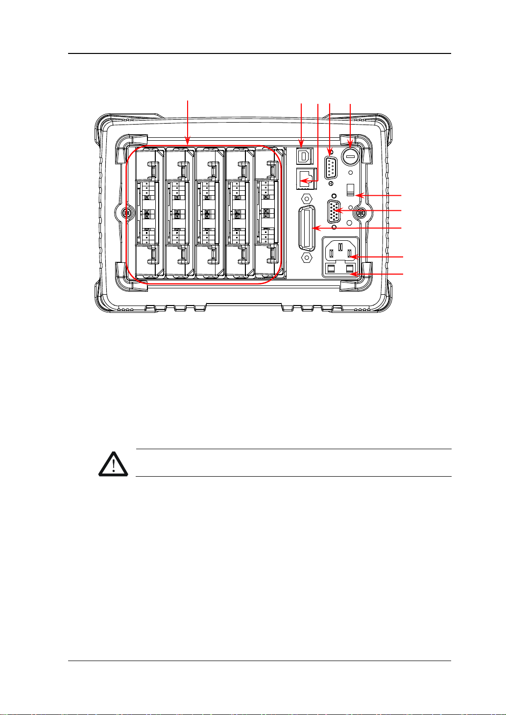
Figure 4 M300 Rear Panel
1. Slots
M300 provides 5 slots for 5 modules. The 5 slots from left to right in the figure
above correspond to the 5 module indicators at the front panel respectively.
When a module is inse rted in the slot, the correspond ing module indi cator at the
front panel goes on. Figure 4 is the schematic diagra m of the rear panel withou t
any module inserted. For the information of each module, refer to “Plug-in
Module Overview”.
RIGOL
Only a single DMM module is permitted for one mainframe.
2. USB Device Interface
Via this interface, M300 can communi cate with the PC as a sla ve devi ce and yo u
can control it remotely via the PC.
3. LAN
M300 conforms to the LXI Core 2011 Device standard. The instrument can be
connected to the network via this interface and you can control the instrument
remotely via a PC in the same network.
4. Analog Bus Interface (Female)
M300 provides two internal 2-wire analog buses for signal routing as well as an
external analog bus interface (namely analog bus interface). The analog bus
M300 Quick Guide
Page 20

RIGOL
8
CAUTION
6 7 4 5 2 3 1
8
9
Pin
Definition
1
Current Input
2
Lo
3
LoSense
4
--
5
--
6
Hi 7 HiSense
8
Float GND
9
--
interface is a 9-pin female interface.
Analog Bus Interface
5. DMM Module Power Fuse
The AC power supply input from the power socket is divided into two paths with
one for the DMM module and the other for the other circuits. M300 is equipped
with the DMM module power fuse ( AC 250V T250 mA). To replace the fuse, refer
to the method below.
1) Turn off the instrument and remove the power cord.
2) Press down the fuse cover using a st ra ight screw driver an d rotate the
straight screw driver clockwise.
3) Select a proper voltage through the voltage selector.
4) Disassemble the fuse cap and fuse.
5) Replace a specified fuse and install the fuse cap.
Please use the specified fuse to avoid electric shock or fire.
6. Voltage Selector
M300 supports two kinds of AC voltages (115 V and 230 V). Please select the
proper voltage scale according to the AC power used.
7. RS-232/Alarms/Ext Trig Mix Interface (Male)
This is a 25-pin male interface. You can convert this interface into two 9-pin
interfaces using the Mix Interface Convert Cable (accessory); wherein, one is a
9-pin male interface use d as a st andar d RS232 int erface a nd the other is a 9-pin
female interface used for alarm output, external trigger signal input and etc.
M300 Quick Guide
Page 21

RIGOL
9
Pin
Definition
1
Alarm 1 Output
2
Alarm 2 Output
3
Alarm 3 Output
4
Alarm 4 Output
5
Channel Closed Output
6
Ext Trig Input/Channel Advance Input
7
GND
8
Not Used
9
Not Used
6 7 4 5 2 3 1 6 7 4 5 2 3
1
8
9
Pin
Name
Definition
1
--
--
2
RXD
Received Data
3
TXD
T ransmitted Data
4
DTR
Data T erminal Ready
5
SGND
Signal Ground
6
DSR
Data Set Ready
7
RTS
Request To Send
8
CTS
Clear To Send
9
--
--
8
9
RS232: via this interface, M300 can communicate with the PC and you can
control the instrument remotely via the PC.
RS232 Interface
Alarms/Ext Trig: as shown in the figure below, pin 1 to pin 4 are used to
output TTL pulse when an alarm is generated in the corresponding alarm
channel. Pin 6 is used to receive external trigger signal. When an external
digital multimeter is connected for measurement, pin 5 and pin 6 are used
together to control the measurement.
Alarms/Ext Trig Interface
Note:
Pin 5 outputs a TTL negative pulse with about 7μs pulse width at each
measurement completion. The output rate is dependent upon the actual
measurement rate and cannot exceed 1000 times per second.
In external trigger mode, when Pin 6 accepts an external trigger signal with a
pulse width equal to or greater than 2μs and specified edge (press Config,
select “External” trigge r m ode an d se lect “Rising” or “Falling” in the Edge item),
the instrument triggers. If the external trigger signal is a continuous pulse,
please make sure the pulse period is greater than 100μs.
8. GPIB Interface
M300 conforms to the IEEE-488.2 standard. Via this interface, M300 can
communicate with the PC and you can control the instrument remotely via the
PC.
M300 Quick Guide
Page 22
RIGOL
10
CAUTION
scale using the voltage selector.
CAUTION
seat is not short-circuited to avoid electric shock or fire.
9. Power Socket
M300 can accept two kinds of AC power supplies. Use the power cord provided
in the accessories to connect the AC power supply to the instrument via this
socket.
Before connecting the AC power supply, select the correct voltage
10. Power Fuse
The specification of the fuse of M300 is AC 250V T3.15 A. If a new fuse is
required, please refer to the following steps.
1) Turn off the instrument and remove the power cord.
2) Insert a small straight screwdriver into the slot at the power socket and
prize out the fuse seat.
3) Replace a specified fuse.
4) Insert the fuse seat into the slot.
Please use the specified power fuse and make sure that the fuse
M300 Quick Guide
Page 23
11
Power On and Inspection
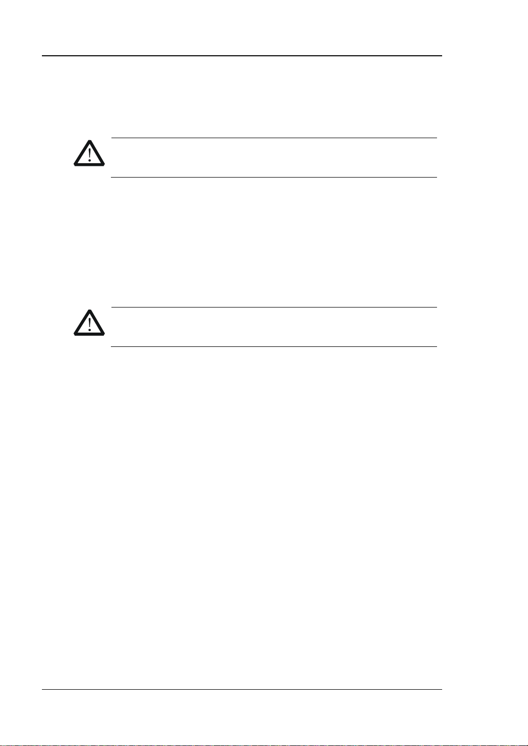
AC Power Input Terminal
1. Connect the power
1) Adjust the power voltage selector at the rear panel according to the power
supply volta ge. M300 suppo rt s two types of AC pow e r inputs:
If your supply voltage is between 115*(1-10%) V and115*(1+1 0%) V,
please select 115.
If it is between 230*(1-10%) V and 230*(1+10%) V, please select 230.
2) Connect the instrument to AC power using the power cord provided in the
accessories.
RIGOL
2. Start the ins t rument
Press the power key at the front panel and the instrument starts.
After the instrument starts, it checks the modules. This process would take
several to dozens of seconds according to the number of modules inserted.
During this process, user operation is forbidden.
3. Check the instrument following the steps below if the instrument
does not start normally
Check whether the powe r is corre ctly connected.
Check whether the power key at the front panel is really on.
Remove the power cord and check whether the voltage selector is at the
correct scale and whether the power fuse is burned out. If the fuse is
burned out, replace it with a specified one.
Restart the instrument after finishing the above inspections.
If it still does not work correctly, please contact RIGOL.
M300 Quick Guide
Page 24
RIGOL
12
Help
Displayed when the built-in help is enabled.
Error
Displayed when an error occurs.
Displayed when the keyboard is locked.
Displayed when an alarm is generated.
Displayed when the system sound is disabled.
Displayed when the instrument is connected to network correctly.
Displayed when an U SB storage device is detect ed.
Local
Displayed when the instrument is in local mode.
Rmt
Displayed when the instrument is in remote mode.
Status
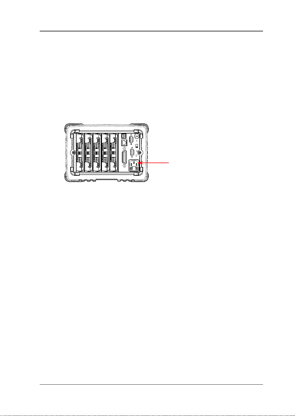
User Interface
Figure 5 User Interface
1. Status Bar
Bar
Content
Bar
Menu
Bar
2. Content Bar
Display the measurement conf iguration guide, measurement parameters
settings and etc. For more detailed information, please refer to the User’s Guide.
3. Menu Bar
Display the menus of the current function. The menus correspond to the menu
softkeys below respectively . Pressing the softkey can activate the corresponding
menu.
M300 Quick Guide
Page 25
RIGOL
13
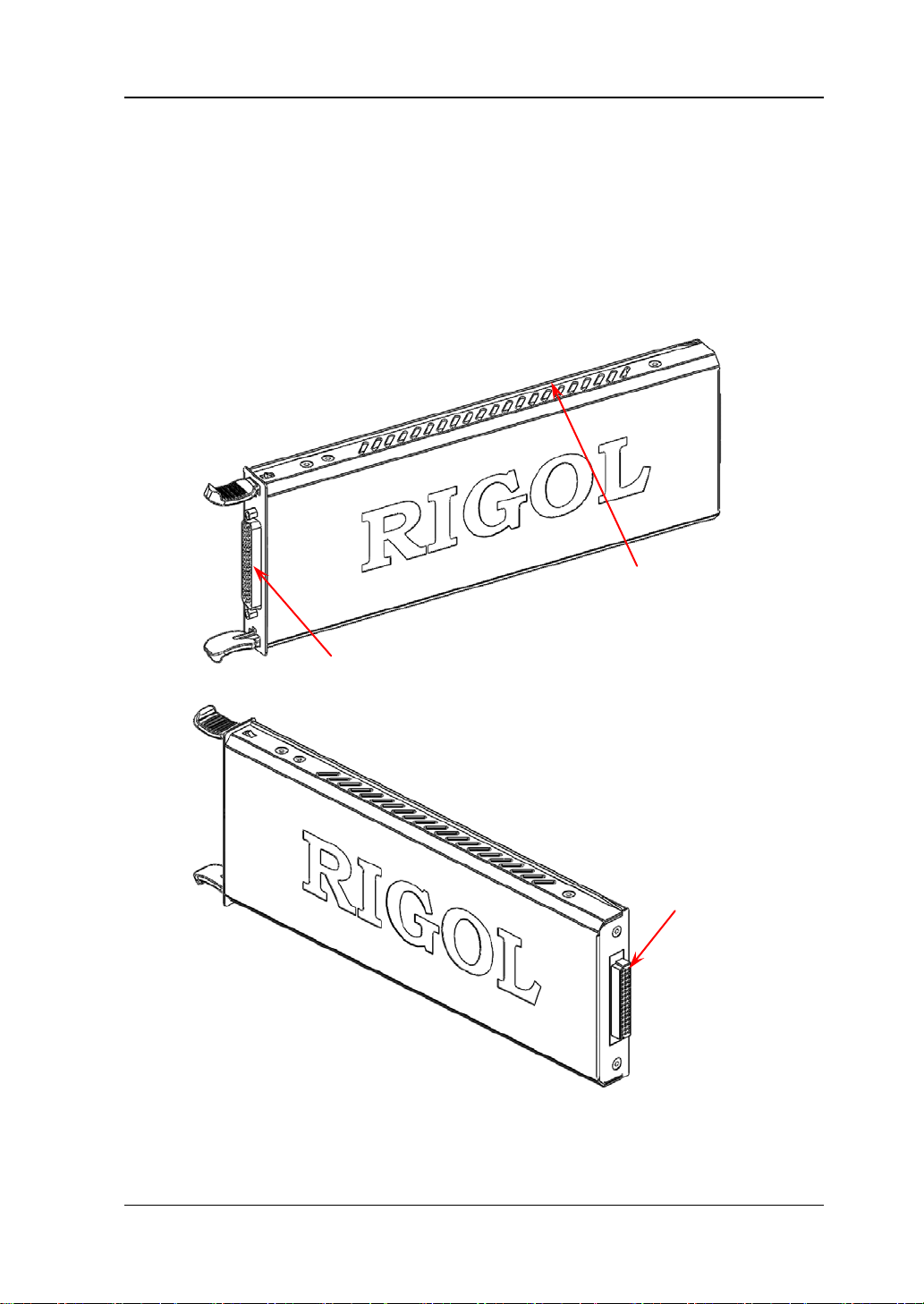
Golden Circuit board Edge: each on the
Interface 1: connect the signal under test via the
Interface 2: connect
Plug-in Module Overview
M300 provides 8 kinds of modules including the DMM module , 20-channel multiplexer,
32-channel multiplexer, 64-channel multiplexer, multi-function module and etc. This
section introduces the functions and characteristics of each module.
Outside View Drawing
top and bottom for sliding into the slot
terminal block (the DMM module does not have this
interface)
with the main frame
Figure 6 Outside View Drawing of the Plug-in Module
M300 Quick Guide
Page 26

RIGOL
14
Note:
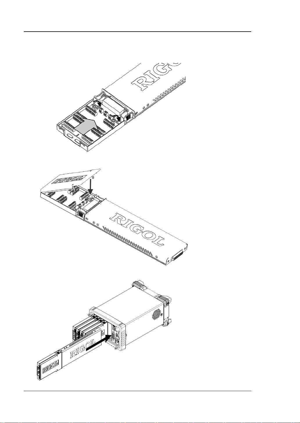
Insert the Module into the Main Frame
Turn the main frame off; and then, insert the modules following the instructions
below.
As shown in Figure 6, there is a golden circuit board edge on the top and bottom of
the module. Aim the two edges with the sli ding chutes (as pointed out by the arrows
in the figure below) in the main frame slot and push the module in until you hear a
sound. At this point, interface 2 is connected to the main frame.
Note: For module that needs to be connected to the signal under measurement,
please refer to “Measurement Connections” to connect the external terminal
block and the signals under measurement before inserting it into the mainframe.
Figure 7 Insert the Module into the Main Frame
All the modules of M300 do not support hot-plugging. Please turn the m ai n frame
off before inserting the modules into the main frame.
M300 Quick Guide
Page 27

15
Module Overview
1. MC3065 (DMM Module):
The DMM module is used to measure the signals under test and provides 6½
digit reading resolution. Its measurement functions include DCV, ACV, DCI, ACI,
2-wire resistance, 4-wire resistance, frequency, period, temperature and any
sensor.
Note: After connecting the DMM module, make sure that the signal under test
connected to the analog bus is no greater than 300 Vdc or 300 Vrms.
2. MC3120 (20-Channel Multiplexer):
All the 20 channels switch both HI and LO inputs, thus providing fully isolated
signals for the DMM module. MC31 20 is divided into two banks (calle d A a nd B)
with 10 two-wire channels in each bank. When making 4-wire resistance
measurement, the instrument automatically pairs channels of A bank and B
bank. All channels in the scan list are b reak -before-make. You can close multiple
channels on this module only if y ou have not configured any channel to be part
of the scan list.
This module can be connected with MC3065 (DMM Module, if MC3065 is
currently inserted).
For the specifications of this module, please refer to the User’s Guide or Data
Sheet of this product.
3. MC3132 (32-Channel Multiplexer):
All the 32 channels switch both HI and LO inputs, thus providing fully isolated
signals for the DMM module. MC31 32 is divided into two banks (calle d A a nd B)
with 16 two-wire channels in each bank. When making 4-wire resistance
measurement, the instrument automatically pairs channels of A bank and B
bank. All channels in the scan list are b reak -before-make. You can close multiple
channels on this module only if y ou have not configured any channel to be part
of the scan list.
This module can be connected with MC3065 (DMM Module, if MC3065 is
currently inserted).
For the specifications of this module, please refer to the User’s Guide or Data
Sheet of this product.
4. MC3164 (64-Channel Single-Ended Multiplexer):
All the 64 channels can only switch HI input. MC3164 is divided into two banks
(A and B) with 32 single-ended channels in each bank. All channels in the scan
list are break-before-make. In any case, you cannot close multi ple channels on
this module.
This module can be connected with MC3065 (DMM Module, if MC3065 is
currently inserted) but cannot be used for 4-wire resistance measurement.
For the specifications of this module, please refer to the User’s Guide or Data
Sheet of this product.
RIGOL
M300 Quick Guide
Page 28

RIGOL
16
5. MC3324 (24-Channel Multiplexer):
All the 20 voltage channels switch both HI and LO inputs, thus providing fully
isolated inputs for the DMM module. The 20 voltage channels are divided into
two banks (called A and B) with 10 two-wire channels in each bank. When
making 4-wire resistance measurement, the instru ment aut omatic all y pairs
channels of A bank and B bank. All channels in the scan list are
break-before-make. You can close multiple channels on this module only if you
have not configured any channel to be part of the scan list.
The 4 current channels are used in combination with the DMM module to
perform DC current or AC current measurement. All channels in the scan list are
break-before-make. In any case, you cannot close multiple channels on this
module.
This module can be connected with MC3065 (DMM Module, if MC3065 is
currently inserted).
For the specifications of this module, please refer to the User’s Guide or Data
Sheet of this product.
6. MC3416 (16-Channel Actuator):
MC3416 can connect signal to the device under test or enable external device.
Any of the 16 channels can switch to Normally-Open (NO) and Normally-Closed
(NC) states.
For the specifications of this module, please refer to the User’s Guide or Data
Sheet of this product.
7. MC3534 (Multifunction Module):
It provides 3 kinds of functions with 4 channels for each function. This module
can be used to check status or control external device (such as the solenoid,
power relay and microwave switch). Y ou can also read the digital inputs and the
totalizer count during a scan.
Four 8–bit digital input/output (DIO) ports
4 totalizer (TOT) input terminals (the first two channels are 10 MHz TOT
and the other two channels are 100 kHz TOT) with 1 Vpp sensitivity
4 analog output terminals, ±12 V calibrated voltage
For the specifications of this module, please refer to the User’s Guide or Data
Sheet of this product.
8. MC3648 (4×8 Matrix Switch):
MC3648 is used to connect multiple devices to multiple points on the device
under test. Y ou can conne ct the rows and columns of multiple mat rix switches to
form relatively larger matrix (such as 8×8 and 4×16, the number of crosspoints
cannot exceed 160).
32 two-wire crosspoints which can connect any combination of inputs and
outputs at the same time. For the specifications of this module, please refer to
the User’s Guide or Data Sheet of this product.
M300 Quick Guide
Page 29

RIGOL
17
To Use the Built-in Help System
The built-in help syst em of M300 p rovides the hel p informat ion about an y front panel
key and menu. T o acquire the help i nformation of a ny front panel key or menu, press
Help (the backlight goes on and “Help” is displayed in the status bar in the user
interface) and then press the desired key or menu. The built-in help interface is as
shown in the figure below. Pressing OK can exit the built-in help system.
Figure 8 Built-in Help Syste m
Menu Quick Navigation
This section provides the structure diagrams of the main menus for M300 to guide
users to quickly get familiar with the operation methods of M300. Fo r more detailed
information, please refer to the User’s Guide.
M300 Quick Guide
Page 30

RIGOL
18
Config
M300 Quick Guide
Page 31

19
Monitor
RIGOL
View Switch Key
M300 Quick Guide
Page 32

RIGOL
20
Control
Alarm Channel Setting Keys
M300 Quick Guide
Page 33
RIGOL
21
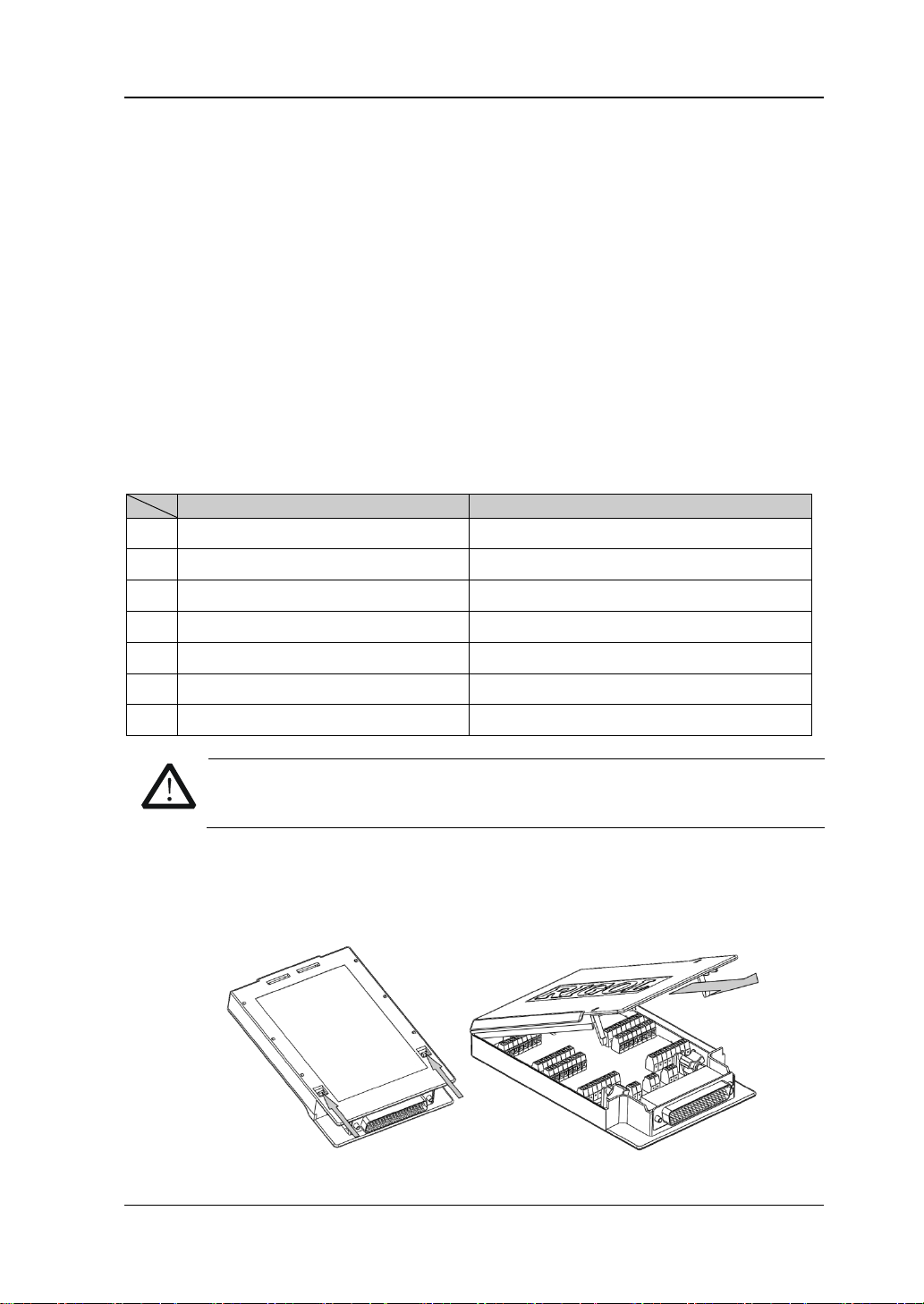
Terminal Block
Module
3.
WARNING
removing the terminal block from the module.
Basic Operations
This section introduces the basic operations of M300, including how to connect the
signals to be measured, how to configure the scan list as well as how to control the
instrument remotely.
Measurement Connections
Multiple signals to be measured are connected to the plug-in modules through the
external terminal blocks and then are switched to the DMM module or external DMM.
M300 provides 7 kinds of terminal blocks. The models of the terminal blocks and
their corresponding modules are listed in the table below. This section introduces
how to connect the signals to be measured through the external blocks.
Table 1 External Terminal Blocks
M3TB20 MC3120
1.
M3TB32 MC3132
2.
M3TB64 MC3164
M3TB24 MC3324
4.
M3TB48 MC3648
5.
M3TB16 MC3416
6.
M3TB34 MC3534
7.
Cut off all the power supplies before opening the terminal block or
1. Place the terminal block with the front (with the RIGOL caption) facing
downward; pull the two latches in the arrow direction in the f igure below and
press them down. Place the termi nal block wit h the front f acing upwar d and pull
the upper cover of the terminal block upward and remove it.
M300 Quick Guide
Page 34

RIGOL
22
01
H
L
H
L
...
H
L
H
L
...
H
L
16
17
32
Channel
Switches
Terminal
Box: TB32
H
L
01
H
L
32
.
.
.
78-Pin
Interface
M300
Mainframe
DMM Module
MC3065
+
V
measured
V
measured
Fuse
Fuse
2. Connect the cables for connecting the signal under test according to the labels
on the circuit board of the terminal block (for the connecting method, refer to
Table 2). Pass the binding wire s through th e two gro ups of holes as pointed out
by the arrows in the figure below to fix the cable connected. Pay attention to the
channel or terminal connected to the cable to ensure that the signal connected
is correct.
Note:
For the connection method of each module and the corresponding terminal
block as well as the specif ic ation requirements of the connecting cable,
please log in RIGOL official website (www.rigol.com) get more related
materials.
When usin g the mutliple x er module for measu rement, make su re that both
the amplitude of the signal under measurement and the commom mode
voltage are no greater than the maximum input voltage of the module.
When the multiplexer mod ule is used to measure an object with high-power
output ability (such as battery and power supply), to avoid damagi ng the
relay, you are recommended to connect a fuse in serial when making
connections (as shown in the figure below).
M300 Quick Guide
Page 35

23
Table 2 Measurement Connections
DCV/ACV/FREQ/PERIOD/Sensor
DCI/ACI/Sensor (DCI)
MC3324.
2WR/RTD/Thermistor/
4WR/RTD 4W/Sensor (4WR)
Thermocouple
WARNING
sure that all the input signals are within the rated input range.
Resistance to be
+
+ - -
RIGOL
(DCV, FREQ)
+ -
Signal to be
measured
CH1
Sensor (2WR)
+ -
Resistance to be
measured
CH1
H L
H L
+ -
Signal to be
measured
CH21
H L
Note: Only available for CH21 to CH24 of
H L Source
CH1
measured
+ -
Thermocouple
to be measured
CH1
To avoid elec t ric shock, the measurement cables should meet the
H L
Note: Only available for all the channels of
MC3120 and MC3132 as well as CH1 to CH20
of MC3324.
maximum voltage requirement. To avoid damaging the module, make
M300 Quick Guide
H L Sense
CH17
Page 36
RIGOL
24
3. Connect the terminal block to i nt erf ace 1 (the interface definition is in Figure 6)
on the module and sc rew down the two screw rods to fix them onto the nuts on
the module.
4. Close the upper cover of the terminal block.
5. Insert the module connected with the terminal block into the slot of the main
frame.
M300 Quick Guide
Page 37

RIGOL
25
To Configure Scan List
Create a scan list and add any channels of the multiplexer or the DIO or TOT
channels of the multifunction module to the scan list; then, configure the basic
measurement, scaling, alarm and advanced measurement parameters for each
channel. The edited scan list can be stored in internal or external memory and be
recalled when required.
1. Create a new list
Press Config New, input the desired list name and press OK.
Note: The existing scan li st will be o verwritten by th e scan list currently created.
2. Set the sc an parameters
(1) Select Sweep and use the left/right direction key to select “Infinite” or “1”
(you need to set a value and the range is from 1 to 50000).
(2) Select Trigger M ode and use the left/right direction key to select “Auto”,
“Manual”, “External”, “AbsTime” or “Alarm”.
(3) If “Auto” is selected, please select Interval and use the numeric keyboard
to set a de sired interval. The range i s from 00:00:00.000 to 99:59:59.999
(the time format is Hour:Minute:Second.Millisecond) and the default is 0.
If “External” is selected, please select Edge and use the left/right direction
key to select “Rising” or “Falling”.
If “AbsTime” is selected, please select AbsTime and use the numeric
keyboar d t o s et a desired time. The time format is “Month-Date
Hour:Minute:Second”.
If “Alarm” is selected, please select Channel and use the left/right direction
key to select “Alarm1”, “Alarm2”, “Alarm3” or “Alarm4”.
3. Configure a channel to the scan list (taking the DCV measurement
function as an example
Press ConfigEditNew to enter the channel configuration guide.
(1) Step 1: Measuremen t Conf i guration
Select Chan No. and use the left/right direction key to select the desired
channel number (for example, 101);
Select Function and use the left/right direction key to select the desired
function (for example, DCV);
Select Range and use the left/right direction key to select the desired
range (for example, 2 V).
Note: The parameters need to be set in this step depend on the
measurement function selected.
(2) Step 2: Scaling Configuration
Select Scaling and use the left/right direction key to enable the scaling
)
M300 Quick Guide
Page 38

RIGOL
26
configuration;
Select A, B and C and use the numeric keyboard to input the desired
scaling coefficients;
Select x1 and press Curr Value to ac quire x1.
Select Unit and input the desired unit.
Note: For multiplexer channel using the “SENSOR” function and the DIO
and TOT channels of the multi f unctio n mo dule, the configuration guide
does not contain scaling conf iguration. Besides, for multiplexer channel, if
the DMM m odule is not currently inserted or it is inserted but is not enabled,
the configuration guide also does not contain “Scaling Configuration” when
an external DMM is connected to execute scan and measurement.
(3) Step 3: Alarm Configuration
Select Mode and use the left/right direction key to select the desired alarm
mode (for example, HI);
Select Channel and use the left/right direction key to select the desired
alarm channel (for example, Alarm1);
Select HI or LO and use the numeric keyboard to input the desired alarm
limit (for example, 12).
Note: For multiplex er channel, if the DMM module is not currentl y i nserted
or it is inserted but is not enabled, the configuration guide d oes not contain
“Alarm Configuration” when an external DMM is connected to execute scan
and measurement.
(4) Step 4: Advanced Configuration
Select Integ and use the left/right direction key to select the desired
integration time (for example 1PLC);
Select IMP and use the left/right direction key to select 10MΩ or >10GΩ;
Select AZ and use the left/right direction key to select “ON” or “OFF”;
Select Delay and use the left/right direction key to “Auto” or set the de lay
time manually.
Note: The parameters need to be set in this step depend on the
measurement function selected.
Press Done to finish the channel configuration guide and return to the s can
list editing interface.
4. Configure other channels to the scan list
Press New and configure other channels to the scan list according to step 3.
5. Save the scan list
After the scan list configuration is completed, you can press Save to save the
conf igured scan list in the internal or external memory of the instrument.
M300 Quick Guide
Page 39

RIGOL
27
Configuration Copy
M300 provides the configuration copy function (include module copy, channel copy
and extended copy) which can be used to quickly configure multi-channels with the
same configuration to the scan list.
Press Config Edit Copy to ente r the configuration copy interfac e.
1. Module Copy:
Copy the configuration of a module (source module) to another module (target
module) of the same mode l. After that, t he configura tion of each channe l of t he
source module is copied to the target module automatically.
Press Module in the configuration copy interface to open the module copy
interface.
(1) The “Source Module” area is selected by default. Use the up/down directio n
key to select the desired source module.
(2) Press Switch to move the cursor to the “Target Module” area and use the
up/down direction key to select the desired target module.
(3) Press OK to execute module copy.
Note: The source module and target module selected must be of the same
model. The configuration of a module to itself is not supported.
2. Channel Copy:
Copy the configuration of a channel (source channel) to another channel or
multiple channels (target channel) of the same type.
Press Channel in the configuration copy in terface to open the channel copy
interface. B y default, the channel selected is fixed as the source channel and the
upper area is selected. At this p oint, use the left/right direction key to select th e
desired target channel and press OK (pressing OK again will give up the
selection); press Done to execute channel copy.
After opening the channel copy interface, you also can press Switch to fix the
channel selected as the target channel. At this point, the lower area is selected.
Use the left/right direction key to select the desired source channel and press
Done to execute channel copy.
Tips:
(1) When the channel selected is fixed as the source channel, multiple target
channels can be selected and will be displayed in the lower area.
(2) When the channel selected is fixed as the target channel, only a single
source channel can be selected.
(3) Switch is graye d o u t and disabled if the current scan list only has a single
M300 Quick Guide
Page 40

RIGOL
28
channel.
Note: For channel copy, only copies between channels of the same type
(namely, channels of the same type of modules) are allowed.
3. Extended Copy:
Copy the configuration of a channel (source channel ) of a module to all the
channels (of which the type i s the same t o that of the source channel) of the
target module.
Press Extended in the configuration copy interface to open the extended copy
interface.
(1) The “Source Channel” area is selected by default. Use the direction keys to
select the desired source channel.
(2) Press Switch to move the cursor to the “Target Module” area and use the
up/down direction key to select the desired target module.
(3) Press OK to execute extended copy.
Note: For extended copy, on ly copies among the same type of modules are
allowed. This function makes it easy to configure several channels with the
same configurations.
Channel Monitor
The channel monitor function of M300 allows users to monitor a single channel,
multiple channels or all of the channels in the sca n list. The instrument monito rs the
channel and takes readings from the channel monitored contin uously even during a
scan. This function is helpful for troubleshooting your system before a test or for
observing important signals.
The channel monitor function can monitor the following channels: multiplexer
channels (configured to the scan list and the DMM module is ena bled), DIO and T O T
channels of the multifuncti on module (no mat ter wh ether the y are configured to the
scan list and the DMM module is not required). Press Monitor at the front panel to
configure the channel monitor functi on.
1. Single-chan n el Monitor
Press Monitor Single to enter the single-channel monitor interface. By
default, the first channel in the scan list is monitored. If no scan list is currently
configured, the first channel of the multifunction module (DIO channel) is
monitored. Only a single channel can be monitored at a time; but you can
change the channel being monitored at any time. Readings acquired during the
monitor process are displayed on the screen but will not be stored in memory.
When the alarm function is applied to the channel being monitored, all the alarm
M300 Quick Guide
Page 41

RIGOL
29
data will be stored in the alarm queue (the data will be cleare d at power-off). To
monitor a multiplexer channel, the DMM module must be installed and enabled
(Utility DMM “ON”); the channel to be m onit ore d must be configured to
the scan list. You can monitor a DIO or TOT channel even if the channel is not
configured to the scan list.
2. Multi-channel Mon ito r
Press Monitor Multiple to enter the multi-channel monitor interface. At
most 7 channels can be monitored. You can add or delete the channels being
monitored.
3. All Channel Monitor
Press Monitor All Moni to enter the all channel monitor interface. All the
channels in the scan list can be monitored.
Remote Control
M300 can communicate wit h PC through USB , LAN, G PIB and RS232 (con verted fr om
the [RS-232/Alarms/Ext Trig] interface at the rear panel of M300) to realize
remote contr ol ba s e d o n the SCPI (Stand ar d Commands for Programmable
Instruments) commands. This section introduces how to use the PC software Ultra
Sigma of RIGOL to control the instru ment remotely t hro ugh the USB interface. For
the detailed inf ormation about the SCPI commands, please refer t o the Prog rammi ng
Guide.
1. Install Ultra Sigma
Download Ultra Sigma from RIGOL website (
according to the instructions.
2. Control the in s tr ument via USB
(1) Connect the devices
Connect the USB Device i nterf ace of M300 to th e USB H ost interface of your
computer using a USB cable.
(2) Install the USB driver
As this instrument is a USB-TMC device, after you connect it to the PC and
turn both on f or th e first time, Found New Hardware Wizard is display ed on
the PC. Please install the “USB Test an d Measurement Device (IVI)” driver
following the directions in the wizard.
(3) Search for device resources
Start up Ultra Sigma and the software will automatically search for the
instrument resources currently connected to the PC. Yo u can also click
to search for the resources.
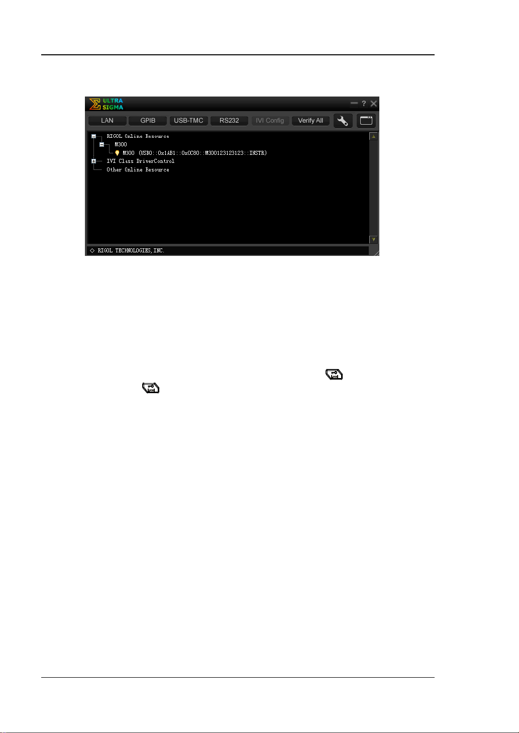
(4) View the device resource
The resources found will appear under the “RIGOL Online Resource”
www.rigol.com) and install it
M300 Quick Guide
Page 42
RIGOL
30
directory and the model number and USB interface information of the
instrument will also be displayed as shown in the f igure below.
Figure 9 View USB Instrument Reso urce
(5) Send Command/Read Data
Right click the resource name “M300
(USB0::0x1AB1::0x0C80::M300123123123::INSTR))” and select “SCPI
Panel Control” to turn on the remote command contr ol panel th rough which
you can send commands and read data.
Note: When the instrument is in remote m ode, Rmt is displaye d in the st atus bar in
the user interface and all the k eys at the front panel (except
point, you can press
to exit the r emote mode.
) are locked. At this
M300 Quick Guide
Page 43

RIGOL
31
Troubleshooting
When the failures listed below occur, please solve them according to the following
steps. If the problem remains, please contact RIGOL and provide the system
information of your instrument (Utility Info).
1. The instrument does not start.
1) Check whether the power cord is correctly connected.
2) Check whether the power switch at the front panel is really on.
3) Remove the power cord; check whether the volta ge sele ctor is at the proper
scale and whether the pow er in put fuse is burned out. If the fuse is burned
out, replace it with a specified one.
4) Restart the instrument after executing the above inspections.
5) If the problem remains, please contact RIGOL.
2. The USB storage device cannot be recognized.
1) Check whether the USB storage device can work norm a l l y.
2) Make sure the USB storage device used is Flash type, as this instrument
does not support hardware type USB storage device.
3) Restart the instrument and insert th e USB stor age devic e to check it.
4) If the USB storage device still cannot work normally, please contact
RIGOL.
3. How to recover the configurations from the last power failure or
unexpected shutdown and continue the work before the shutdown
automatically?
Restart the instrument. Press Utility System, select Power-off using the
up/down direction key and select “ON” using the left/right direction key.
4. The screen is too dark.
Press Utility System, select Brightness using the up/down direction key
and set a proper brightne s s using the left/right direction key.
5. The instrument is locked.
1) Check whether the instrument is in remote mode (namely check whether
“Rmt” is displayed in the status bar in the user interface). If yes, you can
press
2) Check whether the front panel of the instrument is locked (namely check
whether
can press and hold
3) Check whether a progress bar is displayed in the interface. If yes, please
wait and try again until the progress bar disappears.
4) If the problem remains, please restart the instrument.
to exit the remote mode and unlock the front panel.
is displayed in the status bar in the user interface). If yes, you
to unlock the front panel.
M300 Quick Guide
Page 44

RIGOL
32
6. How to change the system language?
Press Utility System, select Language using the up/down direction key
and select the desired language using the left/right direction key.
7. How to view the information and model number of the plug-in
modules?
Press Utility Test; select the desired module using the left/right direction
key and press View to view the information and model number of th e module
currently selected.
8. The corresponding indicator at the front panel does not go on when
the module has been inserted?
1) Press Utility Test; select the desired module using the left/right
direction key and press Re-test.
2) If the problem remains, press View. If the information of the module
cannot be viewed, please refer to the failure 9.
3) If the information of the module can be viewed, the module indicator is
possibly damaged. Please contact RIGOL for maintenance information.
9. Unable to view the information of the module or unable to use the
module when the module has been inserted?
1) Turn the main frame off and remove the module from the main frame;
insert the module into the mainframe again f irmly.
2) Restart the main frame, wait f or about 1 minut e and try t o view the module
information again.
3) If the problem remains, please contact RIGOL.
10. Unable to make configurations or operations related to the DMM
module when it has been inserted?
1) Make sure that Utility System DMM is set “ON”.
2) Press Utility Test; select the DMM mo dule using the left/right direction
key and press View to view whether the information of the DMM module is
normal. If the information is not displayed or is not displayed correctly, it is
possibly that the DMM module is working abnormally due to high current or
power load failure. At this point , please t ur n t he main frame off and restart
it a few minutes later.
3) If the problem remains, please contact RIGOL.
11. The GPIB interface cannot work normally?
1) Check whether the cable works normally and the connection is correct and
reliable.
2) Make sure that the GPIB addresses of M300 and the PC are ide ntical.
3) If the problem remains, please contact RIGOL.
M300 Quick Guide
Page 45

33
12. The USB Device interface cannot work normally?
1) Check whether the cable works normally and the connection is correct and
reliable.
2) Check whether the “USB Test and Measurement Device (IVI)” drive
program has been correctly installed on your PC.
3) If the problem remains, please contact RIGOL.
13. The RS232 interface cannot work normally?
1) Make sure that the RS232 interface parameters (such as the baud rate)
settings of M300 and the PC are identical.
2) Check whether the RS232 cable is a cross cable.
3) If the problem remains, please contact RIGOL.
14. The LAN interface cannot work normally?
1) Check whether the cable works normally and the connection is correct and
reliable.
2) Check the IP configuration mode:
If DHCP is enabled, please make sure that the current network
supports DHCP configuration mode and can distribute network
parameters (such as the IP address) to M300 automatically.
If DH CP is disabled and Auto IP is enabled, please check whether the
IP addresses automatically acquired by M300 and the ne t w ork
paramet e rs of the PC are in the same network segment.
If only Manual IP is enabled, please make sure that the network
parameter settings of M300 and the PC are in the same network
segment.
3) If the problem remains, please contact RIGOL.
RIGOL
M300 Quick Guide
 Loading...