

Page 1

RIGOL
User’s Guide
M300 Series
Data Acquisition/Sw itch System
Dec. 2014
RIGOL Technologies, Inc.
Page 2

Page 3

RIGOL
Guaranty and Declaration
Copyright
© 2013 RIGOL Technologies, Inc. All Rights Reserved.
Trademark Information
RIGOL is a registered trademark of RIGOL Technologies, Inc.
Publication Number
UGC07110-1110
Software Version
00.02.00.04.19
Software upgrade might c hange or add prod uct feat ures. Please a cqui re the la test
version of the manual from RIGOL website or contact RIGOL to upgrade the
software.
Notices
RIGOL products are covered by P.R.C. and foreign patents, issued and
pending.
RIGOL reserves the right to modify or change parts of or all the
specif ications and pricing policies at company’s sole decision.
Information in this publica tion re places all previ ously corresponding material.
Information in this publication is subject to change without notice.
RIGOL shall not be liable for either incidental or consequential losses in
connection with the furnishing, use or performance of this manual as well as
any information contained.
Any part of this document is forbidden to be copied, photocopied or
rearranged without prior written approval of RIGOL.
Product Certification
RIGOL guara nte es t his product conforms t o t he national and indus trial standards
in China as well as the ISO9001:2008 stan da rd and the ISO14001:20 04 standard.
Other international standard conforman ce certifications are in progress.
Contact Us
If you have any problem or requirement when using our products or this manual,
please contact RIGOL.
E-mail: service@rigol.com
Website: www.rigol.com
M300 User’s Guide I
Page 4

RIGOL
Safety Requirement
General Safety Summary
Please review the following safety precautions carefully before putting the
instrument into operation so as to avoid any personal injury or damage to the
instrument and any product connected to it. To prevent potential hazards, please
use the instrument only specified by this manual.
Use Proper Power Cord.
Only the power cor d desig ned fo r the ins trument and authorized for us e within the
local country could be used.
Ground the Instrument.
The instrument is grounded through the Protective Earth lead of the power cord.
To avoid electric shock, it is essential to connect the earth terminal of the power
cord to the Protective Earth terminal before connecting any inputs or outputs.
Connect the Probe Correctly.
If a probe is used, do not connect the ground lead to high voltage since it has
isobaric electric potential as the ground.
Observe All Terminal Ratings.
To avoid fir e or sh ock hazard, observe all ratings and markers on the instrument
and check your manual for more information about ratings before connecting the
instrument.
Use Proper Overvoltage Protection.
Make sure that no overvoltage (such as that caused by a thunderstorm) can re ach
the product, or else th e op erator might be exposed to the danger of electrical
shock.
Do Not Operate Without Covers.
Do not operate the instrument with covers or panels removed.
II M300 User’s Guide
Page 5

RIGOL
Do Not Insert Anything Into the Holes of Fan.
Do not insert anything int o the holes of the fan to avoid damaging t he inst rument .
Use Proper Fuse.
Please use the specified fuses.
Avoid Circuit or Wire Exposure.
Do not touch exposed junctions and components when the unit is powered.
Do Not Operate With Suspected Failures.
If you suspect damage occurs to the instrument, have it inspected by RIGOL
authorized personnel before further oper at io ns. Any maintenance, adjustment or
replacement especially to circuits or accessories must be performed by RIGOL
authorized personnel.
Keep Well Ventilation.
Inadequate ventilation may cause an increase of instrument temperature which
would cause damage to the instrument. So please keep the instrument well
ventilated and inspect the intake and fan regularly.
Do Not Operate in Wet Conditions.
In order to avoid short circuiting to the interior of the device or electric shock,
please do not operate the instrument in a humid environment.
Do Not Operate in an Explosive Atmosphere.
In order to avoid damage to the device or personal injuries, it is important to
operat e the devi ce away from an explosive atmospher e.
Keep Product Surfaces Clean and Dry.
T o a void the influence of dus t and/or moisture in the air, please keep the surface of
the device clean and dry.
Electrostatic Prevention.
Operate the instrument in an electrostatic discharge protective environment to
avoid damage induced by static discharges. Always ground both the internal and
external conductors of cables to release static before making connections.
M300 User’s Guide III
Page 6

RIGOL
Proper Use of Battery.
If a battery is supplied, it must not be exposed to high temperature or in contact
with fire. Keep it out of the reach of children. Improper change of battery (n ote:
lithium battery) may cause explosion. Use RIGOL specified battery only.
Handling Safety.
Please handle with care during transportation to avoid damage to buttons, knob
interfaces and other parts on the panels.
IV M300 User’s Guide
Page 7
RIGOL
CAUTION
DANGER
Hazardous
Safety
Protective
Terminal
Chassis
Test
Safety Terms and Symbols
Terms Used in this Manual. These terms may appear in this manual:
WARNING
Warning statements indicate conditions or practices that could result in
injury or loss of life.
Caution statements indicate conditions or practices that could result in
damage to this product or other property.
Terms Used on the Product. These terms may appear on the Product:
It calls attention to an operation, if not correctly pe rformed, could
result in injury or hazard immediately.
WARNING It calls attention to an operation, if not correctly pe rformed, could
result in
CAUTION It calls attention to an operation, if not correctly pe rformed, could
result in
product.
Symbols Used on the Product. These symbols may appear on the product:
potential injury or hazard.
damage to the product or other devices connected to the
Voltage
Warning
Earth
Ground
Ground
M300 User’s Guide V
Page 8

RIGOL
Allgemeine Sicherheits Informationen
Überprüfen Sie diefolgenden Sicherheitshinweise
sorgfältigumPersonenschädenoderSchäden am Gerätundan damit verbundenen
weiteren Gerätenzu vermeiden. Zur Vermeidung vonGefa hren, nutze n S ie bitte das
Gerät nur so, wiein diesem Handbuchangegeben.
Um Feuer oder Verletzungen zu vermeiden, verwenden Sie ein
ordnungsgemäßes Netzkabel.
Verwenden Sie für dieses Gerät nur das für ihr Land zugelassene und genehmigte
Netzkabel.
Erden des Gerätes.
Das Gerät ist durch den Schutzleiter im Netzkabel geerdet. Um Gefahren durch
elektrischen Schlag zu vermeiden , ist es unerlässlich, die Er dung durchzufüh ren. Erst
dann dürfen weitere Ein- oder Aus gä nge verbunden werden .
Anschluss einesTastkopfes.
Die Erdungsklemmen der Sonden sindauf dem gleichen Spannungspegel des
Instruments geerdet. SchließenSie die Erdungsklemmen an keine hohe Spannung
an.
Beachten Sie alle Anschlüsse.
Zur Vermeidun g von Feuer oder Stromschlag, beachten Sie alle Bemerkungen und
Markierungen auf dem Instrument. Bef olgen Sie die Bedienun gsanleitung für weitere
Informationen, bevor Sie weitere Anschlüsse an das Instrument legen.
Verwenden Sie einen geeigneten Überspannungsschutz.
Stellen Sie sicher, daß keinerlei Überspannung (wie z.B. durch Gewitter verursacht)
das Gerät erreichen kann. Andernfallsbestehtfür den Anwender die
GefahreinesStromschlages.
Nicht ohne Abdeckung einschalten.
Betreiben Sie das Gerät nicht mit entfernten Gehäuse-Abdeckungen.
Betreiben Sie das Gerät nicht geöffnet.
Der Betrieb mit offenen oder entfernten Gehäuseteilen ist nicht zulässig. Nichts in
entsprechende Öffnungen stecken (Lüfter z.B.)
Passende Sicherung verwenden.
Setzen Sie nur die spezifikationsgemäßen Sicherungen ein.
Vermeiden Sie ungeschützte Verbindungen.
Berühren Sie keine unisolierten Verbindungen o der Baugrup pen, während das Gerät
VI M300 User’s Guide
Page 9

RIGOL
in Betrieb ist.
Betreiben Sie das Gerä t n ic h t i m Fehlerfall .
Wenn Sie am Gerät einen Defekt vermuten, sorgen Sie dafür, bevor Sie das Gerät
wieder betreiben, dass eine Untersuchung durch RIGOL autorisiertem Personal
durchgeführt wird. Jedwede W artun g, Einstellarbeit en oder Austausch v on Teilen am
Gerät, sowie am Zubehör dürfen nur von RIGOL autorisiertem Personal
durchgeführt werden.
Belüftung sicherstellen.
Unzureichende Belüftung kann zu Temperaturanstiegen und somit zu thermischen
Schäden am Gerät führen. Stellen Sie deswegen die Belüftung sicher und
kontrollieren regelmäßig Lüfter und Belüftungsöffnungen.
Nicht in feuc h te r Um g ebung betreiben.
Zur Vermeidun g von Kurzschluß im Geräteinne ren und Stromschlag betreiben Sie das
Gerät bitte niemals in feuchter Umgebung.
Nicht in explosiver Atmosphäre betreiben.
Zur Ve rm e idung von Personen- und Sachschäden ist es unumgänglich, das Gerät
ausschließlich fernab jedweder explosiven At mosphäre zu betreiben.
Geräteoberflächen sauber und trocken halten.
Um den Einfluß von Staub und Feuchtigkeit aus der Luft auszuschließen, halten Sie
bitte die Geräteoberflächen sauber und trocken.
Schutz gegen elektrostatische Entladung (ESD).
Sorgen Sie für eine elektrostatisch geschützte Umgebung, um somit Schäden und
Funktionsstörungen durch ESD zu vermeiden. Erden Sie vor dem Anschluß immer
Innen- und Außenleiter der V erbindungsleitung, um st atische Aufladung zu entladen.
Die richtige Verwendung desAkku.
Wenneine Batterieverwendet wird, vermeiden Sie hohe Temperaturen bzw. Feuer
ausgesetzt werden. Bewahren Sie es außerhalbder Reichweitevon Kindern auf.
UnsachgemäßeÄnderung derBatterie (Anmerkung: Lithium-Batterie) kann zu einer
Explosion führen. VerwendenSie nur von RIGOL angegebenenAkkus.
Sicherer Transport.
Transportieren Sie das Gerät sorgfältig (Verpackung!), um Schäden an
Bedienelementen, Anschlüssen und anderen Teilen zu vermeiden.
M300 User’s Guide VII
Page 10

RIGOL
WARNING
Schäden oder den Tod von Personen zur Folge haben können.
CAUTION
Schäden am Gerät hervorrufen können.
DANGER
weist auf eine Verletzung oder Gefährdung hin, die sofort
geschehen kann.
WARNING
weist auf eine Verletzung oder Gefäh rdung hin, die möglicherweise
nicht sofort geschehen.
CAUTION
weist auf eine Verletzun g ode r Gefährdung hin und bedeutet, dass
Gegenstände auftreten kann.
Sicherheits Begriffe und Symbole
Begriffe in diesem Guide. Diese Begrif fe können in diesem Handbuch aufta uchen:
Die Kennzeichnung WARNING beschreibt Gefahren quellen die leibliche
Die Kennzeichnung Caution (Vorsicht) beschreibt Gefahrenquellen die
Begriffe auf dem Produkt. Diese Bedingungen können auf dem Produkt
erscheinen:
eine mögliche Beschädigung des Instruments oder anderer
Symbole auf dem Produkt. Diese Symbole können auf dem Produkt erscheinen:
GefährlicheS
pannung
SicherheitsHinweis
Schutz-erde Gehäusemasse Erde
VIII M300 User’s Guide
Page 11
RIGOL
IX
CAUTION
WARNING
To avoid injury resulting from short circuit, make sure the instrument is
completely dry before reconnecting to a power source.
General Care and Cleaning
General Care
Do not store or leave the instrument where it may be exposed to direct sunlight for
long periods of time.
Cleaning
Clean the instrument regularly according to its operating conditions. To clean the
exterior surface, perform the following steps:
1. Disconnect the instrument from all power sources.
2. Clean the loose dust on the outside of the i nstrument with a lint -f ree cloth (with
a mild detergent or water). When cleaning the LCD, take care to av oid sca rifying
it.
To avoid damag e t o t he instrument, do not expose it to caustic liquids.
Environmental Consideratio ns
The following symbol indicates that this product complies with the applicable WEEE
Directive 2002/96/EC.
Product End-of-Life Handling
The equipment may c ontain s ubstan ces that could b e ha rmful t o the envi ronm ent o r
human health. In order to avoid release of such su bstances into the en vironment and
harm to human health, we encourage you to recycle this product in an appropriate
system that will ensure that most of the materials are reused or recycled
appropriately. Please contact your local authorities for disposal or recycling
information.
M300 User’s Guide
Page 12

RIGOL
M300 Overview
The M300 series data acquisition/switch system provides 5 slots to accept any
combina tion of 8 kinds of plug-in modules, including a DMM module, multiple
multiplexers, an actuator, a matrix switch module and a multifunction module . With
its modular structure, it combines precision measurement capability with flexible
signal connections and can provide versatile solutions for the applications that
require multiple points or signals t o be tested. This can be especially useful in
product performance testing during the R&D phase, and automatic test during
production process.
It com e s with a 4.3 inch high-re s olution color LCD, us e r -friendly interface design,
easy-to-use keyboard layout as well as clear key backlight and operation prompts.
The M300 i s extremly flexible an d easy to use. F or remote cont rol versatil ity , it co mes
with RS232, USB, LAN and G PIB interfaces standard.
Main Features:
Up to 320 switch channels per mainframe (with very low cost per channel)
Can run independently without PC
USB data logging
Interval scanning with storage of up to 100,000 time-stamped readings
8 modules supported
6½ digit DMM can be inserted into any slot. It als o supports multiple
measurement functions, including DCV, DCI, ACV, ACI, 2WR, 4WR, PERIOD,
FREQ, TEMP (Thermocouple, Thermistor and RTD) and any sensor.
Standard multiple communication interface: USB Device, USB Host, GPIB,
LAN(LXI Core 2011 Device) and RS232
Standard SCPI commands for remote programming capability
Math statistics function: AVG, MAX, MIN and SDEV
Friendly interface
Built-in help system
Multiple system language
4.3 inch c olor LCD
PC control and analysis software
X M300 User’s Guide
Page 13

RIGOL
XI
Document Overview
Main topics in this manual:
Chapter 1 Quick Guide
This chapter introduces the front panel, rear panel, user interface and plug-in
modules of the M300 as well as the precautions when using it for the first time.
Chapter 2 Front Panel Oper ations
This chapter introduces in details t he fr ont pane l ope ration methods and f unctions o f
M300.
Chapter 3 To Use External DMM
This chapter illustrates the method of connecting external DMM and configuring scan
list to scan.
Chapter 4 Remote Control
This chapter introduces how to control the M300 remotel y.
Chapter 5 Troubleshooting
This chapter introduces the commonly encountered failures and their solutions.
Chapter 6 Specifications
This chapter provides the performance specifications and general technical
parameters of the M300.
Chapter 7 Appendix
This chapter provides the accessory list of the M300 as well as service and support
information.
M300 User’s Guide
Page 14

RIGOL
Format Conventions in this Manual:
1. Key:
The front panel k ey is denot ed by th e for mat of “Text Box + But ton Na me (Bold)”.
For example, Utility denotes the Utility key.
2. Menu:
The menu is denoted by th e format of “Chara cter Shading + Menu W ord (Bold)”.
For examp le, System denotes the system menu item of the Utility function
key.
3. Operation Steps:
The next step of operation is denoted by an arrow “”. F or e xampl e, Utility
System denotes pressing Utility at the front panel and then pressing System.
User Manuals of This Product:
The main user manuals of this product include the Qui ck Guide , User’s Guide,
Programmi ng Guide and Data sheet. Users can download the desire d manual fr om
www.rigol.com.
XII M300 User’s Guide
Page 15

Contents RIGOL
XIII
Contents
Guaranty and Declaration ......................................................................... I
Safety Requirement ................................................................................ II
General Safety Summary ........................................................................... II
Safety Terms and Symbols ........................................................................ V
Allgemeine Sicherheits Informationen ........................................................ VI
Sicherheits Begriffe und Symbole ............................................................ VIII
General Care and Cleaning ....................................................................... IX
Environmental Considerations ................................................................... IX
M300 Overview ........................................................................................ X
Document Overview ............................................................................... XI
Chapter 1 Quick Guide ........................................................................ 1-1
General Inspection ................................................................................ 1-2
Appearance and Dim e nsions ................................................................... 1-3
Front Panel ........................................................................................... 1-4
Rear Panel ............................................................................................ 1-8
Power On Inspection ............................................................................ 1-12
User Interface ...................................................................................... 1-13
To Input Filename ................................................................................ 1-14
Plug-in Module Overview ....................................................................... 1-16
Outside View Drawing of the Module................................................ 1-16
Insert the Module into the Mainframe .............................................. 1-17
Module Overview ........................................................................... 1-18
To Use the Built-in Help System ............................................................. 1-20
Measurement Connections .................................................................... 1-21
To Replace the Fuse ............................................................................. 1-25
Menu Quick Navigation ......................................................................... 1-26
Config .......................................................................................... 1-26
Monitor ......................................................................................... 1-27
View Switch Key ............................................................................ 1-27
Control ......................................................................................... 1-28
Alarm Channel Setting Ke ys ............................................................ 1-28
Chapter 2 Front Panel Operations ...................................................... 2-1
Scan Configuration ................................................................................ 2-2
Scan List ........................................................................................ 2-2
Trigger Mode .................................................................................. 2-8
Channel Configuration .................................................................... 2-12
Channel Configuration When Using External DMM ............................. 2-21
Measurement Parameter Configuration ............................................ 2-22
Digital Input .................................................................................. 2-35
Totalizer ........................................................................................ 2-37
M300 User’s Guide
Page 16

RIGOL Contents
Configuration Copy ........................................................................ 2-39
Channel Monitor ................................................................................... 2-44
Single-channel Monitor ................................................................... 2-44
Multi-channel Monitor .................................................................... 2-46
All Channel Monitor ........................................................................ 2-46
Module Control .................................................................................... 2-47
To Control MC3120 ........................................................................ 2-48
To Control MC3132 ........................................................................ 2-51
To Control MC3164 ........................................................................ 2-54
To Control MC3324 ........................................................................ 2-56
To Control MC3416 ........................................................................ 2-59
To Control MC3534 ........................................................................ 2-61
To Control MC3648 ........................................................................ 2-64
Alarm Channel Setting .......................................................................... 2-66
View Switch ......................................................................................... 2-68
Scan History Information ................................................................ 2-68
Channel Status Table ..................................................................... 2-70
Measurement Curve ....................................................................... 2-70
Channel Information ...................................................................... 2-72
Store and Recall ................................................................................... 2-73
File Type ....................................................................................... 2-74
Internal Storage ............................................................................ 2-75
External Storage ............................................................................ 2-75
To Save a File ................................................................................ 2-76
Utility .................................................................................................. 2-77
System Setting .............................................................................. 2-78
I/O Configuration .......................................................................... 2-86
System Information ....................................................................... 2-92
Detect .......................................................................................... 2-92
System Update .............................................................................. 2-93
Chapter 3 To Use External DMM ......................................................... 3-1
To Connect Instruments .......................................................................... 3-2
To Configure the Instruments .................................................................. 3-4
Scan Control Method .............................................................................. 3-5
Chapter 4 Remote Control ................................................................. 4-1
User-defined Programming ..................................................................... 4-2
To Use PC Software ................................................................................ 4-6
To Control M300 through GPIB .......................................................... 4-6
To Control M300 through USB ........................................................... 4-8
To Control M300 through RS232 ........................................................ 4-9
To Control M300 through LAN ......................................................... 4-11
Chapter 5 Troubleshooting ................................................................ 5-1
Chapter 6 Specifications .................................................................... 6-1
DC Charac t eristic s .................................................................................. 6-1
XIV M300 User’s Guide
Page 17

Contents RIGOL
XV
AC Characteristics .................................................................................. 6-3
Frequency and Period Characteristics ...................................................... 6-6
Temperature Characteristics ................................................................... 6-8
Module Specifications ........................................................................... 6-10
MC3120/MC3132/MC3164/MC3324/MC3416/MC3648 ........................ 6-10
MC3534 ........................................................................................ 6-12
General Specifications ........................................................................... 6-13
Chapter 7 Appendix ............................................................................ 7-1
Appendix A: A cces sories and Options List ................................................ 7-1
Appendix B: Definitions of the Pins of the 78-pin Interface of the Plug-in
Modules ............................................................................................... 7-2
MC3120 ......................................................................................... 7-2
MC3132 ......................................................................................... 7-3
MC3164 ......................................................................................... 7-4
MC3324 ......................................................................................... 7-5
MC3416 ......................................................................................... 7-6
MC3534 ......................................................................................... 7-7
MC3648 ......................................................................................... 7-8
Appendix B : Warranty ............................................................................ 7-9
Index ....................................................................................................... 1
M300 User’s Guide
Page 18

Page 19

Chapter 1 Quick Guide RIGOL
1-1
Chapter 1 Quick Guide
This chapter guides users to quickly get familiar with the front/rear panels, user
interface as well as the measurement connections of the M300.
Topics in this chapter:
General Inspection
Appearance and Dim e nsions
Front Panel
Rear Panel
Power On Inspection
User Interface
To Input Filename
Plug-in Module Overview
To Use the Built-in Help System
Measurement Connections
To Replace the Fuse
Menu Quick Navigation
M300 User’s Guide
Page 20

RIGOL Chapter 1 Quick Guide
General Inspection
1. Inspect the shipping container for damage.
Keep the damaged shipping container or cushioning material until the contents
of the shipment have been checked for completeness and the instrument has
passed both elec trical an d mechanical tests.
The consigner or carrier shall be liable for the damage to instrument resulting
from shipment. RIGOL would not be responsible for free mai ntenance/rework
or replacement of the unit.
2. Inspect the instrument.
In case of any damage, or defect, or failure, notify your RIGOL sales
representative.
3. Check the Accessories
Please check the accessories according to the packing lists. If the accessories
are incomplete or damaged, please contact your RIGOL sales representative.
1-2 M300 User’s Guide
Page 21
Chapter 1 Quick Guide RIGOL
1-3
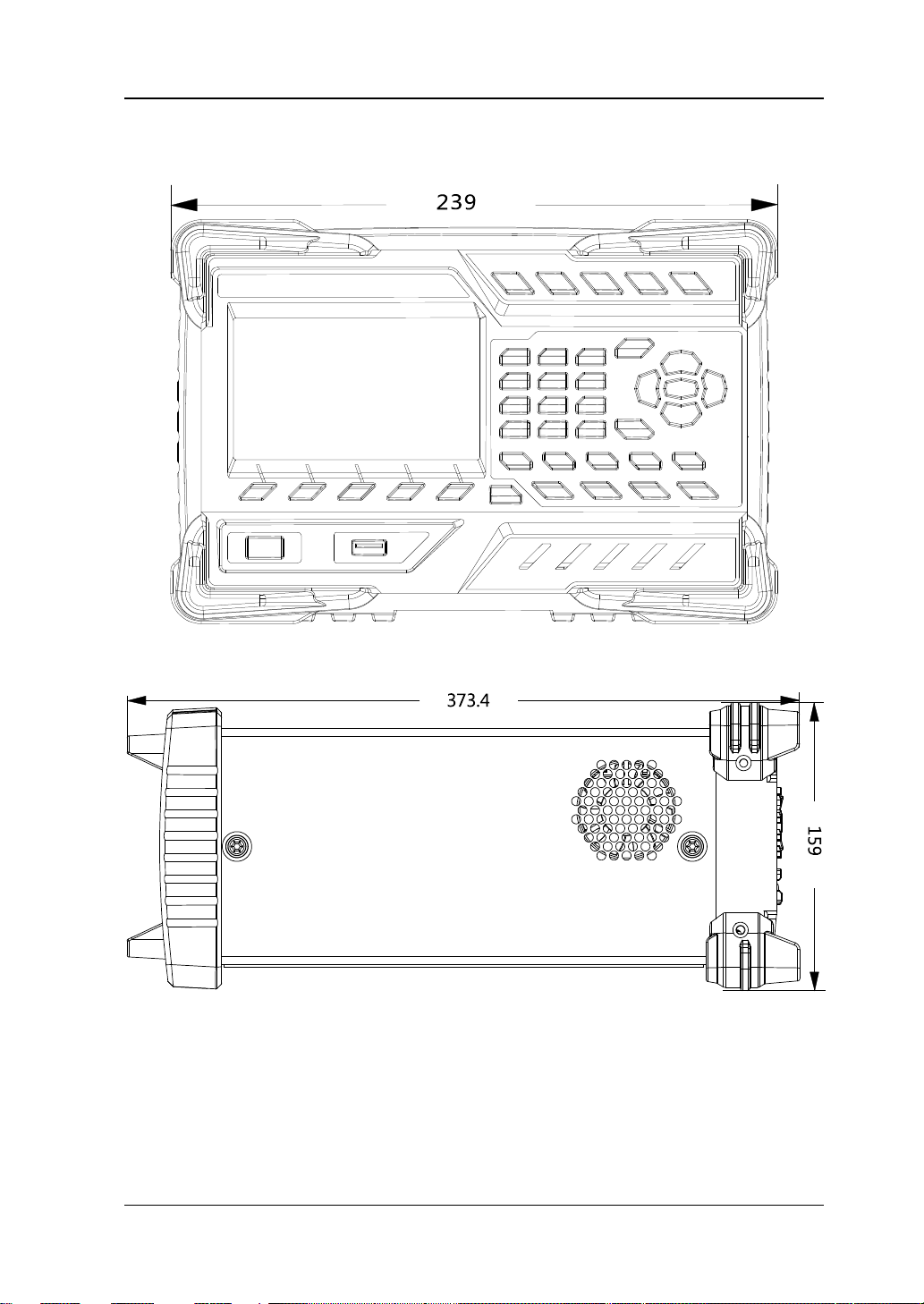
Appearance and Dimensions
Figure 1-1 Front View (Unit: mm)
Figure 1-2 Side View (Unit: mm)
M300 User’s Guide
Page 22
RIGOL Chapter 1 Quick Guide
Configure the scan list and the measurement parameters of each
Enable or disable the channel monitor function.
channels in the scan list.
1 2
6 7 8 9 10
3
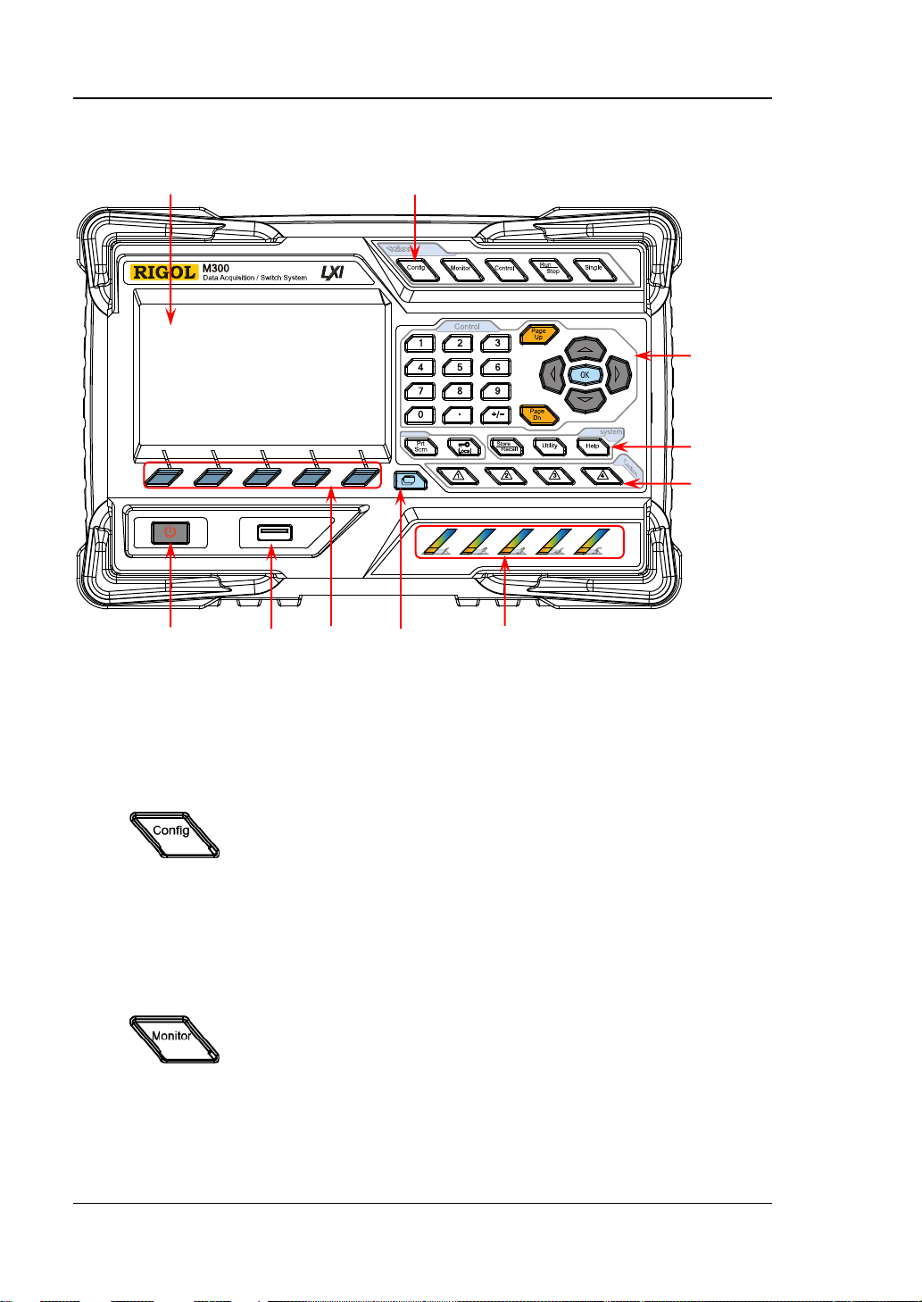
Front Panel
4
5
Figure 1-3 Front Panel of M300
1 LCD
4.3 inches high-resolution color LCD displaying the menu, configuration guide,
measurement parameters, system status and prompt messages.
2 Function Keys
channel.
Create, edit, read and save the scan list.
Set the number of scans, trigger mode and scan interval.
Provide the channel configuration guide used to configure
the measurement parameters, scaling parameters, alarm
parameters and advanced measurement parameters of the
channel.
Support single-channel, multi-channel and all-channel
monitor functions.
1-4 M300 User’s Guide
In single-channel monitor function, you can switch the
channel monitored at any time.
In multi-channel monitor function, you can monitor up to 7
Page 23
Chapter 1 Quick Guide RIGOL
1-5
In all-channel monitor function, you can monitor all the
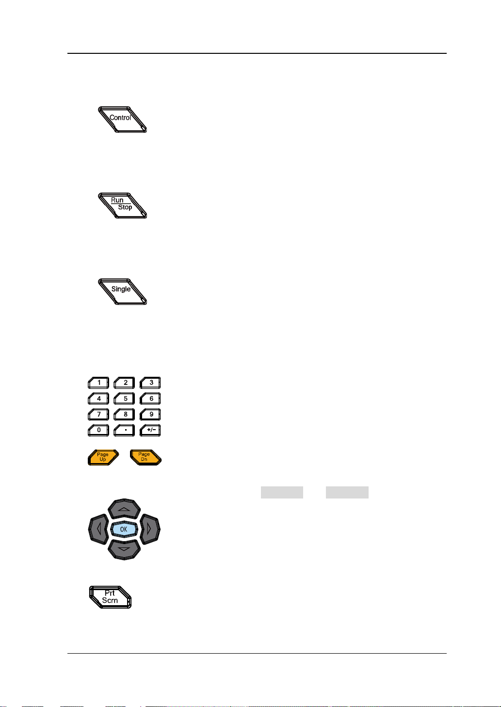
Control the modules currently inserted.
Auto Trigger/Stop
Single-channel Switch
single-channel monitor interface.
Numeric Keyboard
Use this key to open the previous or next page of the
up/down keys (Page Up and Page Dn).
If a USB storage device is currently c onnected to t he ins trument,
storage device in *.bmp format.
channels in the scan list.
Control the status of each channel of the modules.
Reset the modules.
Configure the DIO and TOT channels of multifunction
module.
Can not control the DMM module.
Press this key, the instrument triggers or enters the
wait-for-trigger state and the backlight goes on. Press and hold
this key, the instrument stops triggering or exits the
wait-for-trigger state and the backlight goes off.
Note: This key is invalid when the scan list is empty.
When the instrument is in the single-channel monit or interface,
press this key to switch the channel monitored to the next
channel in the scan list. When the instrument is in other
interfaces, press this key to switch the instrument to the
3 Control Keys
Include numbers (0-9), decimal point (.) as well as
positive/negative signs (+/-).
Used to input parameter value, date and time.
current interface.
Note: These keys are different from the menu page
Direction keys and conf irmation key.
4 System Keys
press this key to store the current content on the screen in USB
M300 User’s Guide
Page 24
RIGOL Chapter 1 Quick Guide
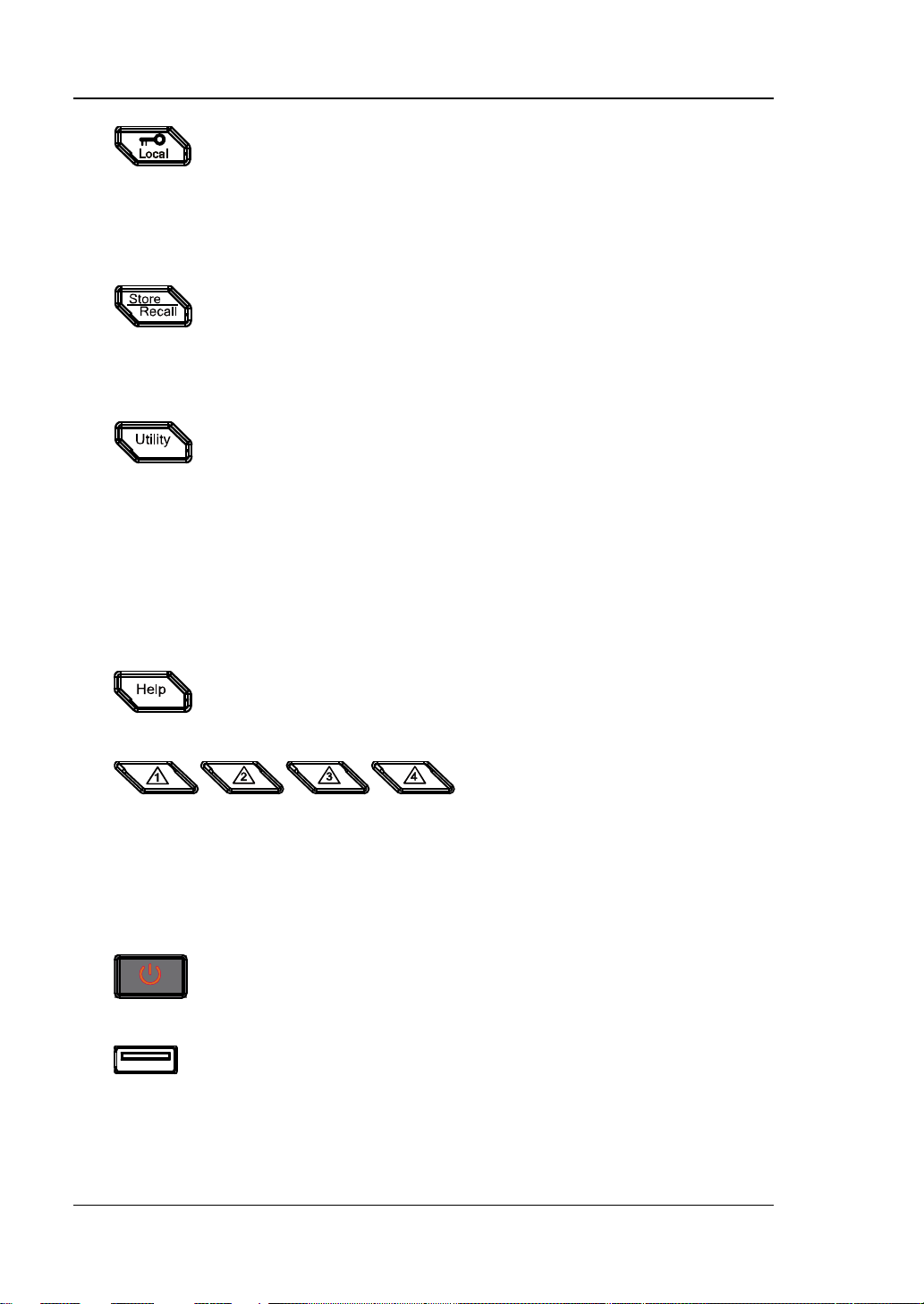
When the instrument is in local mode, pressing this key can
Store and reca ll the system configurarion, measurement
Configure the system-related parameters.
Enable the built-in help system. Provide Chinese/English help
information for the front panel function keys and menu items.
Press this key to turn on or off the instrument.
Via this interface, M300 can be as a host device and connected
measurement configuration, measurement data, etc.
lock the front panel. At this point, all the keys at the front
panel except this key become invalid. Press a nd hold this key
to unlock the front panel.
When the instrument is in remote mode, press this key to
switch to local mode.
conf iguration and measurement data, etc.
Store the file in the internal non-volatile memory or externa l
USB storage device.
Read the file stored.
Set various parameters such as the time, date, system
language and display brightness.
Configure the remote inte rface parame t e rs : RS232, LAN,
GPIB and USB.
Query the system information (su ch as t he model and serial
number).
Execute self-test and view the information of each module
(such as the name and model of the module).
System update.
5 Alarm Channel Setting
M300 provides 4 alarm channels. When an alarm is generated, the
corresponding pin of the Alarms/Ext Trig interface (converted from the
[RS-232/Alarms/Ext Trig] interface) at the rear panel outputs a pulse. You
can press the corresponding key to set the output mode of the corresponding
pin.
6 Power Key
7 USB Host
with an USB storage device to store or recall instrument status,
1-6 M300 User’s Guide
Page 25

Chapter 1 Quick Guide RIGOL
1-7
View the scan history information, channel status table, measurement
error messages (up to 20).
8 Menu Softkeys
Correspond to the menus on the screen. Pressing any softkey can enable the
corresponding menu.
9 View Switch
curve and channel information.
Scan history information: view the start time, scan sweep, count,
channel number as well as the corresp ondi ng function, maximum,
minimum, average and standard deviation meas ure d and the sc an
readings of each channel of the latest scan.
Channel status table: display the current status of each channel.
Measurement curve: display the measurement curve of the
specified channel.
Channel information: view the cycle count of each relay of the
module, the alarm messages of the current scan (the first 100,
including the reading and time when the alarm is generated) and
Note: Up to 100 alarm messages on each alarm channel can be logged in the
alarm queue and the other alarm messages would be lost and up to 20 error
messages can be logged in the error queue and the other error messages will
also be lost.
10 Module Indicators
Correspond to the 5 module slots at the rear panel respectively. The
corresponding module indicator goes on when the module is inserted into the
slot at the rear panel.
M300 User’s Guide
Page 26

RIGOL Chapter 1 Quick Guide
CAUTION
10
6
7
8
9
Rear Panel
1 Slots
The M300 provides 5 slots for 5 modules. The 5 slots from left to right in the
figure above correspond to the 5 module indicators at the front panel
respectively. When a module is inserted in the slot, the corres pon din g module
indicator at the front panel goes on. Figure 1-4 is the schematic diagram of the
rear panel without the modules inserted. For information of each module, refer
to “Plug-in Module Over vie w ”.
1 2 3 4 5
Figure 1-4 Rear Panel of M300
2 USB Device
3 LAN
4 Analog Bus Interface (Female)
1-8 M300 User’s Guide
Only one DMM module is permitted for one mainf r ame.
Via this interface, M300 can communi cate with the PC as a sla ve devi ce and yo u
can control it remotely via the PC.
M300 conforms to the LXI Core 2011 Device standard. The instrument can be
connected to the network via this interface and you can control the instrument
remotely via a PC in the same network.
M300 provides two internal 2-wire analog buses for signal routing as well as an
Page 27

Chapter 1 Quick Guide RIGOL
1-9
CAUTION
6
7
4
5
2 3 1
8
9
Pin
Definition
1
Current Input
2
Lo
3
LoSense
4
--
5
--
6
Hi 7 HiSense
8
Float GND
9
--
external interface (namely Analog Bus Interface). The analog bus interface is a
9-pin female interface.
Analog Bus Interface
5 DMM Module Power Fuse
The AC power supply from the power socket is divided into two paths with one
for the DMM module and the other for other circuits except the DMM module.
M300 is equipped with the DMM module power fuse (AC 250V T250 mA). To
replace the fuse, refer to the method below.
1) Turn off the instrument and remove the power cord.
2) Press down the fuse cover using a straight screw driver and rotate
clockwise.
3) Select a proper voltage through the voltage selector.
4) Disassemble the fuse cap and fuse.
5) Replace a specified fuse and install the fuse cap.
Please use the specified fuse to avoid electric shock and fire.
6 Voltage Selector
M300 supports two kinds of AC voltages (115 V and 230 V). Please select the
proper voltage scale according to the AC power used.
M300 User’s Guide
Page 28

RIGOL Chapter 1 Quick Guide
Pin
Definition
1
Alarm 1 Output
2
Alarm 2 Output
3
Alarm 3 Output
4
Alarm 4 Output
5
Channel Closed Output
6
Ext Trig Input/Channel Adv a nce Inp ut
7
GND
8
Not Used
9
Not Used
6 7 4 5 2 3 1 6 7 4 5 2 3
1
8
9
Pin
Name
Definition
1
--
-- 2 RXD
Received Data
3
TXD
T ransmitted Data
4
DTR
Data T erminal Ready
5
SGND
Signal Ground
6
DSR
Data Set Ready
7
RTS
Request To Send
8
CTS
Clear To Send
9
--
--
8
9
7 [RS-232/Alarms/Ext Trig] Mixed In terface (Male)
This interface is 25-pin male interface. You can convert this interface into two
9-pin interfaces using the Mixed Interface Convert Cable (accessory). This
breakout cable consists of a 9-pin male in terface us ed as a standard RS232
interface and another a 9-pin female interface used for alarm output, external
trigger signal input, etc.
RS232: via this interface, M300 can communicate with the PC and you can
control the instrument remotely via the PC.
RS232 Interface
Alarms/Ext Trig: as shown in th e figure below, pin 1 to pin 4 are use d to
output TTL pulse when an alarm is generated in the corresponding alarm
channel. Pin 6 is used to receive external trigger signal. When an external
digital multimeter is connected for measurement, pin 5 and pin 6 are used
together to control the measurement.
Alarms/Ext Trig Interface
Note:
The Pin 5 outputs a TTL negative pulse with about 7μs pulse width each time the
measurement is completed. The output rate is dependent upon the actual
measurement rate. The maximum output rate is 1000 times per second.
In external trigger mode, Pin 6 accepts external trigger signal. The trigger can
have a pulse width equal to or greater than 2μs with specified edge. To
configure, press Config , select “External” trigger mode and select “Rising” or
1-10 M300 User’s Guide
Page 29
Chapter 1 Quick Guide RIGOL
1-11
CAUTION
Before connecting the AC power supply, select the correct voltage
scale using the voltage selector.
CAUTION
seat is not short-circuited to avoid electric shock and fire.
“Falling” in Edge item. If the external trigger signal is continuous pulse, please
make sure the pulse period is larger than 100μs.
8 GPIB
The M300 c onforms t o the IEEE-488.2 standar d. Via this interface, the M300 can
be controlled remotely via a PC with a GPIB interface.
9 Power Socket
The M300 can accept two kinds of AC power supplies. Use the power cord
provided in the accessories to connect the AC power supply to the instrument
via this socket.
10 Power Fuse
The specification of the fuse of M300 is AC 250V T3.15 A. If a new fuse is
required, please refer to “To Replace the Fuse”.
Please use the specif ied power fuse and make sure that the fuse
M300 User’s Guide
Page 30

RIGOL Chapter 1 Quick Guide
AC Power Socket
Power On Inspection
1 Connect the power
(1) Adjust the power voltage selector at the rear panel according to the power
supply volta ge. M300 supports two types of AC power. If your supply
voltage is in the range of 115*(100%-10%) V and115*(1 00%+10%) V,
please select 115 and if it is in the ran ge of 230 *(1 00%-10%) V and
230*(100%+10%) V, please select 230.
(2) Connect the instrument to AC power using the power cord provided in the
accessories.
2 Start the instrument
Press the power key at the front panel and the instrument starts.
After the instrument starts, it checks the modules. This process would take
several to dozens of seconds according to the number of modules inserted.
During this process, user operation is forbidden.
3 Check the instrument following the steps below if the instrument
does not start normally
1) Check whether the power is correctly connected.
2) Check whether the power key at the front panel is really on.
3) Check whether the power fuse is burned out. If the fuse needs to be
changed, use the specified fuse.
4) Check whether the correct power voltage is selected. Please select the
proper power voltage according to the power supply voltage.
5) Restart the instrument after f inishing the above inspections. If it still does
not work correctly, please contact RIGOL.
1-12 M300 User’s Guide
Page 31

Chapter 1 Quick Guide RIGOL
1-13
Help
Displayed when the built-in help is enabled.
Error
Displayed when an error occurs.
Displayed when the keyboard is locked.
Displayed when an alarm is generated.
Displayed when the system sound is disabled.
Displayed when the instrument is connected to a network correctly.
Displayed when an U SB storage device is detected.
Local
Displayed when the instrument is in local mode.
Rmt
Displayed when the instrument is in remote mode.
Status
User Interface
Bar
Content
Area
Menu
Figure 1-5 User Interface
1. Sta tus Bar
Bar
2. Cont ent Area
Display the measurement configuration guide, measurement parameters
settings, etc. For more detailed information, please refer to the User’s Guide.
3. Me nu Bar
Display the menus of the current function corresponding to the menu softkeys
below respectively. Pressing the softkey can activate the corresponding menu.
M300 User’s Guide
Page 32

RIGOL Chapter 1 Quick Guide
To Input Filename
M300 supports filenames consisting of Chinese characters, English letters and
numbers. The length of the filename can not exceed 12 bytes. The filename input
interface is as shown in the figure below.
Input Mode Icon/Chinese Character Selecting Area Letter Selecting Area
Filename Input Area
Figure 1-6 Filename Input Interface
1 Input Mode Icon/Chinese Character Selecting Area
Display the icon of the input mode currently selected.
Chinese input mode: display
English uppercase input mode: display
English lowercase input mode: display
In additional, in Chinese input mode, this area displays Chinese characters for
selection. Use the numberic keyboa rd to in put the numbe r cor respon ding to the
Chinese character to input the desired Chinese character.
2 Filename Input Area
Display the letter entered. You can use the left/right direction keys to select the
desired letter to edit.
3 Letter Selecting Area
Use the direction keys to select desired letter and press OK.
1-14 M300 User’s Guide
Page 33

Chapter 1 Quick Guide RIGOL
1-15
4 Switch the Input Mode
Press Ch/A/a to switch the input mode to Chinese, English uppercase or
English lowercase.
Chinese: can input Chinese characters and number (from 0 to 9) and
is displayed in the “Input Mode Icon Area”.
English uppercase: can input English uppercase letters (from A to Z) and
number (from 0 t o 9 ) an d
is displayed in the “Input Mode Icon Area”.
English lowercase: can input English lowercase letters (from a to z) and
number (from 0 t o 9 ) an d
is displayed in the “Input Mode Icon Area”.
5 Switch the Cursor
Press Cursor to switch the cursor to select “Filename Input Area”, “Letter
Selecting Area” or “Chinese Character Selecting Area” (only available in Chinese
input mode).
When “Filename Input Area” is selected, you can use left/right direction
keys to select desired letter to edit.
When “Letter Selecting Area” is selected, use the direction keys to select
desired letter and press OK. At this point, letters in “Filename Input Area”
or “Chinese Character Selecting Area” varies.
In Chinese input mode, when “Chinese Character Se lecting Area” is selected,
you can use the up/down direction keys to open the previous or next page
of “Chinese Character Selecting Area” and use the numberic keyboard to
input the number corresponding to the Chinese character to input the
desired Chinese character.
6 Delete
Press this softkey to delete the letter selected by the cursor in “Filename Input
Area”.
7 OK
Press this softkey to use the letters displayed in “Filename Input Area” as the
filename.
8 Return
Press this softkey to cancel inputting filename and return to the pre vious men u .
M300 User’s Guide
Page 34

RIGOL Chapter 1 Quick Guide
Golden Circuit board Edge: each on the
Interface 1: connect the signal under test via the
Interface 2: connect
Plug-in Module Overview
The M300 provides 8 kinds of modules. These include a DMM module, 20-channel
multiplexer, 32-channel multiplexer, 64-channel multiplexer, multi-function module,
etc. This section introduces the functions and characteristics of each module.
Outside View Drawing of the Module
top and bottom for sliding into the slot
terminal block (the DMM module does not have this
interface)
with the main frame
Figure 1-7 Outside view drawing of the modul e
1-16 M300 User’s Guide
Page 35

Chapter 1 Quick Guide RIGOL
1-17
Note:
mainframe off before inserting the modules into the mainframe.
Insert the Module into the Mainframe
Please turn the mainframe off and insert the modules following the instructions
below.
As shown in Figure 1-7, there is a golden circuit board edge both on the top and
bottom of the module. Aim the two edges with the sliding chutes (as pointed out by
the arrows in the figure below) into the main f ra me sl ot and push the module in unti l
you hear a sound. At this point, interface 2 is connected to the main frame.
Note: Please refer to “Measurement Connections” to connect the external
terminal block and the sig nals to be measured and then insert it into the mainf ra me.
Figure 1-8 Insert the Module into the Mainframe
All the modules of the M300 do not support hot-plugging. Please turn the
M300 User’s Guide
Page 36

RIGOL Chapter 1 Quick Guide
Module Overview
MC3065 (DMM Module):
The DMM module is used to measure the signals under test and has 6½ digit reading
resolution. The measurement functions include DCV, ACV, 2-wire resistance, 4-wire
resistance, frequency, period, temperature and any sensor.
After connecting the DMM module, make s ure that the signal under test connected to
the analog bus is no greater than 300 Vdc or 300 Vrms.
MC3120 (20-Channel Multiplexer):
All 20 channels switch both HI and LO inputs, thus providing fully isolated inputs to
the DMM module. MC3120 is divided into two banks (called A and B) of 10 two-wire
channels each. When making 4-wire resistance measureme nt , the instrument
automatically pairs channels of A bank and B bank. All channels in the scan list are
break-before-make. You can close multiple channels on this module only if you have
not configured any channel to be part of the scan list.
This module can be connected with MC3065 (DMM Module, if MC3065 is currently
inserted).
MC3132 (32-Channel Multiplexer):
All 32 channels switch both HI and LO inputs, thus providing fully isolated inputs to
the DMM module. MC3132 is divided into two banks (called A and B) of 16 two-wire
channels each. When making 4-wire resistance measureme nt , the instrument
automatically pairs channels of A bank and B bank. All channels in the scan list are
break-before-make. You can close multiple channe ls on this module only if you have
not configured any channel to be part of the scan list.
This module can be connected with MC3065 (DMM Module, if MC3065 is currently
inserted).
MC3164 (64-Channel Single-Ended Multiplexer):
All 64 channels can switch the HI input only. MC3164 is divided into two banks (A and
B) of 32 single-ended channels each. All channels in the scan list are
break-before-make. In any case, y ou cann ot close multiple channels on thi s module.
This module can be connected with MC3065 (DMM Module, if MC3065 is currently
inserted) but cannot be used for 4-wire resistance measurement.
MC3324 (24-Channel Multiplexer):
The MC3324 is a mixed multiplexer with 20 v oltage channels a nd 4 current channe ls.
All 20 voltage channels switch both HI and LO inputs, thus providing fully isolated
inputs to the DMM module, and is divided into two banks (called A and B) of 10
two-wire channels each. When making 4-wire resistance measurement, the
instrument automatically pairs channels of A bank and B bank. All channels in the
scan list are break-before-make. You can close multiple channels on this module only
if you have not configured any channel to be part of the scan list.
1-18 M300 User’s Guide
Page 37

Chapter 1 Quick Guide RIGOL
1-19
4 current channels are used in combination with the DMM module to measure DC
current or AC current. All channels in the scan list are break-before-make. In any
case, you cannot close multiple channels on this module.
This module can be connected with MC3065 (DMM Module, if MC3065 is currently
inserted).
MC3416 (16-Channel Actuator):
The MC3416 can connect signals to the device under test or enable external devices.
Any of the 16 channels can switch to Normally-Ope n (NO ) a nd N ormal ly -Closed (NC)
states.
MC3534 (Multifunction Module):
This module provides 3 kinds of functions with 4 channels for each function. This
module can be used to check status or control external devices (such as solenoid,
power relays and microwave switches). You can also read digital inputs and the
totalizer count during a scan.
Four 8–bit digital input/output (DIO) ports
4 totalizer (TOT ) input terminals (the first two channels are 10 MHz TO T and the
other two channels are 100 kHz TOT) with 1 Vpp sensitivity
4 analog output terminals, ±12 V calibrated voltage
MC3648 (4×8 Matrix Switch):
The MC3648 is used to connect multiple devices to multiple points on the device
under test. You can connect the rows and columns of multiple matrix switches to
form relatively larger matrix (such as 8×8 and 4×16, the number of crosspoints
cannot exceed 160).
32 two-wire cross points which can connect any com bination of inputs an d outputs at
the same time.
M300 User’s Guide
Page 38

RIGOL Chapter 1 Quick Guide
To Use the Built-in Help System
The built-in help syst em of M300 provides the help information about any front panel
key and menu. To acquire the help information of an y front panel k ey or menu , press
Help (the backlight goes on and “Help” is displayed in the status bar in the user
interface) and then press the desired key. The built-in help interface is as shown in
the fi g ure below. Press OK to exit.
Figure 1-9 Built-in Help System
1-20 M300 User’s Guide
Page 39

Chapter 1 Quick Guide RIGOL
1-21
Terminal Block
Module
1.
M3TB20
MC3120
2.
M3TB32
MC3132
3.
M3TB64
MC3164
4.
M3TB24
MC3324
5.
M3TB48
MC3648
6.
M3TB16
MC3416
7.
M3TB34
MC3534
WARNING
removing the terminal block from the module.
Measurement Connections
Multiple signals to be measured are connected to the plug-in modules through the
external terminal blocks and then switched to the DMM module or external DMM.
M300 provides 7 kinds of terminal b locks. The models of the terminal blocks and
corresponding modules are listed in the table below. This section introduce s how to
connec t the signals to be measured t hrough the external block.
Table 1-1 External Terminal Blocks
Cut off all the power supplies before opening the terminal block or
1. Place the terminal block with the front (with the RIGOL caption) facing
downward and pull the two latches in the a rrow direction in the figure below and
press them down. Place the termi nal block wit h the front f acing upwar d and pull
the upper cover of the terminal block upward and remove it.
2. Connect the cables for connecting the signal under test according to the labels
on the circuit board of the terminal block (for the connecting method, refer to
M300 User’s Guide
Page 40

RIGOL Chapter 1 Quick Guide
01
H
L
H
L
...
H
L
H
L
...
H
L
16
17
32
Channel
Switches
Terminal
Box: TB32
H
L
01
H
L
32
.
.
.
78-Pin
Interface
M300
Mainframe
DMM Module
MC3065
+
V
measured
V
measured
Fuse
Fuse
Table 1-2). Pass the binding wires through the two groups of holes as pointed
out by the arrows in the figure below to fix the cable connected. Pa y attention t o
the channel or terminal connected to the cable to ensure that the signal
connected is correct.
Note:
For the connectio n method of each module and the corresponding terminal
block as well as the specification requirements of the connecting cable,
please log in RIGOL official websi t e (www.rigol.co m) to get more related
materials.
When using the mutliplexer module for measurement, make sure that both
the amplitude of the signal under measurement and the commom mode
voltage are no greater than the maximum input voltage of the module.
When the multiplexer module is use d to measure an object wi th high-power
output ability (such as battery and power supply), to avoid damaging the
relay, you are recommended to connect a fuse in serial when making
connections (as shown in the fi gure below ) .
1-22 M300 User’s Guide
Page 41

Chapter 1 Quick Guide RIGOL
1-23
DCV/ACV/FREQ/PERIOD/Sensor
DCI/ACI/ Sensor (DCI)
channel 24 of MC3324.
2WR/RTD/Thermistor/
4WR/RTD 4W/ Sensor (4WR)
Thermocouple
WARNING
the input signals are within the rated input range.
Resistance to be
+
+ - -
Table 1-2 Measurement Connections
(DCV, FREQ)
+ -
Signal to be
measured
CH1
H L
Sensor (2WR)
+ -
Resistance to be
measured
CH1
H L
+ -
Signal to be
measured
CH21
H L
Note: Only available for the channel 21 to
H L Source
CH1
measured
+ -
Thermocouple
under test
CH1
To avoid electric shock, the connecting wire should meet the maximum
H L
curent requirement. To avoid damaging the module, make sure that all
M300 User’s Guide
H L Sense
CH17
Note: Only available for all the channels of
MC3120 and MC3132 as well as the channel 1
to channel 20 of MC3324.
Page 42

RIGOL Chapter 1 Quick Guide
3. Connect the terminal block t o the mod ule via interfa ce 1 (the interface definition
is in Figure 1-7) on the module and screw down the two screw rods onto the
nuts on the module.
4. Close the upper cover of the terminal block.
5. Insert the module with the terminal block into the slot of the mainframe.
1-24 M300 User’s Guide
Page 43

Chapter 1 Quick Guide RIGOL
1-25
CAUTION
seat is not short-circuited to avoid electric shock and f ire.
To Replace the Fuse
If a new fuse is required, please refer to the following steps.
1 Turn off the instrument and remove the power cord.
2 Insert the small straight screw driver into the slot at the power socket and pry
out the fuse seat.
3 Replace a specified fuse.
4 Insert the fuse seat into the slot.
Please use the specif ied power fuse and make sure that the fuse
M300 User’s Guide
Page 44

RIGOL Chapter 1 Quick Guide
Menu Quick Navigation
This section provides the structures of the main menus for M300 to guide users to
quickly get familiar with the operations. For more detailed information, please refer
to “Front Panel Operations”.
Config
1-26 M300 User’s Guide
Page 45

Chapter 1 Quick Guide RIGOL
1-27
Monitor
View Switch Key
M300 User’s Guide
Page 46

RIGOL Chapter 1 Quick Guide
Control
Alarm Channel Setting Keys
1-28 M300 User’s Guide
Page 47

Chapter 2 Front Panel Operations RIGOL
2-1
Chapter 2 Front Panel Operations
This chapter introduces in details t he fr ont pane l ope ration methods and f unctions o f
M300.
Top ics in this chapter:
Scan Configuration
Channel Monitor
Module Control
Alarm Channel Setting
View Switch
Store and Recall
Utility
M300 User’s Guide
Page 48

RIGOL Chapter 2 Front Panel Operations
Scan Configuration
Press Config at the front panel to configure M300 to create a scan (create and edit
the scan list and configure the parameters of each channel). During the scan, each
time the DMM module is connected to one channel in the scan list and executes a
measurement according to the channel configuration.
Scan List
Create a scan list, add any channels of the multiplexer or the DIO or T OT channels of
the multifunction module to the scan list and configure the basic measurement,
scaling, alarm and adv anced measurement parameters for ea ch c hanne l. The edited
scan list can be stored in i nternal or exte rnal memory and be recalled whe n require d.
To Create a New List
The instrument enters the scan list configuration interface when you start the M300
or press Config. You can set the scan parameters (such as sweep count, tigger
mode) as well as create, edit, recall and save the scan list.
Figure 2-1 Scan List Configuration Interface
1 To Create Scan List
Press New to create a new scan list and enter the filename input interface. At
this point, you can input the desired list name by referring to “
Filename” and press OK. The scan list name can consist of Chinese chara cters,
English uppercase/lowercase letters and numbers and can not exceed 12 bytes
2-2 M300 User’s Guide
To Input
Page 49

Chapter 2 Front Panel Operations RIGOL
2-3
Interval
A Scan
(each English letter or number occupies 1 byte and each Chinese character
occupies 2 byt e s).
To modify the name of the scan list created, please select Scan Li st firstly and
press OK to enter the filename input interface.
2 Sweep Count
Select Sweep using the up/down direction keys and select “ Infinite” or “1” (you
need to set a value) using the left/right direction keys.
Infinite: execute continuous scan. You can press and hold Run/Stop to
stop the scan.
Number of Scans: you can use the numeric keyboard to set a value. The
range is from 1 to 50000 . After executing the specified number of scans, the
instrument stops scanning automatically.
3 Trigger Mode
Select TrigMode using the up/down dire ction k eys and sele ct “Auto”, “Manua l”,
“External”, “AbsTime” or “Alarm” using the left/right direction keys.
Auto: the instrument executes infinite scan or the specified number of
scans at the specified interval automatically.
Manual: the instrument executes a scan when you press Run/Stop.
External: the instrument executes a scan when the external trigger signal
input interface receives a TTL trigger pulse.
AbsTime: the instrument executes a scan when the system t ime reaches the
specif ied time.
Alarm: the instrument executes a s can when an alarm is generated from the
specified alarm channel.
For details of the trigger mode, refer to “Trigger Mode”.
4 Interval
Interval is defined as the time interval between the start of a scan to the start of
the next scan in auto scan mode as show n in the figure below . When the t rigger
mode is “Auto”, select Interval using the up/down direction keys and use the
numeric keyboard to set a desired interval. The range is from 00:00:00.000 to
99:59:59.999 (the time format is Hour:Minute:Second.Millisecond) and the
default is 00:00:00.000.
……
M300 User’s Guide
Page 50

RIGOL Chapter 2 Front Panel Operations
Pin 6: Ext Trig Input/Channel Advance Inp ut
5 Advanced Source (Available only when the DMM module is not
installed or disabled)
This setting is only available when an external digital multimeter is used. The
advanced source provides the advanced channel signal. When receiving the
advanced channel signal, the instrument disconnects the channel currently
selected and closes the next channel in the scan list.
When an external DMM is connected, use the up/down direction keys to select
Adv Src and use the left/right direction keys to select the desired advanced
source.
Auto:
After finishing measuring the current channel, the cur rent channel is
disconnected and the next channel in the list is closed automatically.
Single:
After finished measuring the current channel, the unit will wait for user
input before moving to the next channel in the list. Pressing Single to
disconnect the current channel and close the next channel.
Because both the “Single” advanced source and the manual trigger use the
same way, pressing Single, to generate signal, the manual trigger mode
does not support “Single” advanced source.
External:
The scan will advance after receiving a trigger on the external advanced
channel signal. This signal , typica lly the VMC signal from the external DMM,
is input from pin 6 of the Alarm/Ext Trig interface (converted from the
[RS-232/Alarms/Ext Trig] interface). After “External” is selected, you
need to select the ed ge type of the input signal (use the up/ down direction
keys to select Input Edge and use the left/right direction keys to select
“Rising” or “Falling”).
As the “External” advanced source input and the external trigger input use
the same pin, the external trigger mode does not support “External”
advanced source.
Alarms/Ext Trig Interface
6 Absolute Time
Absolute time is defined as the time when the instrument executes the scan in
2-4 M300 User’s Guide
Page 51

Chapter 2 Front Panel Operations RIGOL
2-5
absolute time scan mo de. When the tri gger mo de is “AbsTime”, select AbsTime
using the up/down direction keys and set the desired time using the numeric
keyboard. The time format is “Month-Date Hour:Minute:Second”. You need to
set a valid time. The ranges of the parameters are as follows.
Month: 01 to 12
Date: 01 to 31, 30, 29 or 28
Hour: 00 to 23
Minute: 00 to 59
Second: 00 to 59
The instrument can also ignore some time parameters and trigger when the
system time fulfills some of the parameters. Use “.” on the numeric keyboard to
set the parameters to be ignore d and the cor responding position will display “ **”.
For example, set the inst rument t o ignore the “ Month” and “Date” and trigger at
8:00 every day; use the numeric keyboard to set the absolute time to “**-**
08:00:00”.
7 Alarm Channel
When the trigger mode is set to “Alarm”, select Channel using the up/down
direction keys and set the alarm channel to “Alarm1”, “Alarm2”, “Alarm3” or
“Alarm4” using the left/right direction keys. The instrument executes a scan
when an alarm is generated from the channel selected.
8 Trigger Edge Type
When the trigger mode is “External”, select Edge using the up/down direction
keys and select “Rising” or “Falling” using the left/right direction keys. The
instrument executes a scan when a TTL trigger pulse with specified edge is
received by the external trigger signal input terminal.
M300 User’s Guide
Page 52

RIGOL Chapter 2 Front Panel Operations
To Edit the List
Press ConfigEdit to enter the scan list editing interface.
Figure 2-2 Scan List Editing Interface
1 New
Create a new channel configuration. Press this softkey to enter the channel
conf iguration guide. Finish all the configurations according to the introductions
in “Channel Configuration” and press Done to return to the scan list editing
interface.
2 Copy
Copy the channel c onfiguration created to other channel or module. For details,
refer to the introduction in “Configuration Copy”.
3 Modify
Modify the channel configuration created. Select the desired channel using the
direction keys and press Modify to open the configuration guide of the
corresponding channel. At this point, you can modify the configuration of this
channel and after the mod ification is finished, press Done to return to the scan
list editing interface.
Note: The channel in Chan No. can only be modified to the channels in the
scan list.
4 Delete
Delete a channel configuration created. Select the channel to be deleted using
the direction keys and press Delete to delete the corresponding channel.
2-6 M300 User’s Guide
Page 53

Chapter 2 Front Panel Operations RIGOL
2-7
5 Search
When a great number of channels are added into the scan list, you can press
Page Dn Search, use the numeric keyboard to input the desired channel
number and then press OK to quickly locate this channel. You can copy, modify
or delete the channel configuration located.
To Save the List
The M300 allows users to save the configured scan list in internal or external
memory as measurement conf iguration file.
Press Config Save to enter the store and recall interface (the file type is
automatically set to “Measurement configuration”). Select the desired directory
according to the method introduced in “Store and Recall” and then press Save to
enter the filename input interface. Input the specified filename to save the current
scan list.
You can read the scan li st stored as well as modify its configuration and sav e it again.
To Read the List
The M300 allows users to read the scan list stored. Press Config Read to enter
the store and recall interface (the file type is set to “Measurement Configuration”
automatically). Select and read the desired file according to the method introduced
Store and Recall”.
in “
You can modify the configuration of the scan list read and save it again.
M300 User’s Guide
Page 54

RIGOL Chapter 2 Front Panel Operations
Trigger Mode
The M300 provides 5 trigger modes including auto trigger, manual trigger, external
trigger, absolute time trigger and alarm trigger.
Auto Trigger
In auto trigger mode, the scan rate is determined by the specified interval. If the
time required for a complet e scan of the scan list is greater than the specified interval,
the instrument will execute a continuous scan at the fastest possib le rate (no e rror
message will be generated).
The range of the interval is from 0 ms to 99:59:59.999 hours (the time format is
“Hour:Minute:Second.Millisecond”) and the resolutio n is 1 ms.
If the number of s cans is set to “Infinite” , press Run/Stop at the front panel and the
instrument executes a continuous scan automatically at the specified interval. You
can press and hold the key to stop the scan.
If the number of scans is a specific value (1 to 5000 0), p ress Run/Stop at the front
panel and the instrument executes the specified number of scans at the specified
interval and then stops automatically.
During the scan, the instrument stores the measurement data, scaling data and
alarm data in the non-volatile memo ry automatically. You can press
panel to view the history measurement data (including the maximum, minimum,
average and standard deviation).
Manual Trigger
In manual trigger mode, after you press Run/Stop at the front panel, the
instrument executes a sca n and then enters the w ait -for-trigger state. After that, the
instrument triggers each time you press Run/Stop at the front panel.
If the n u mber of scans is set to “Infinite”, after each trigger is finished, th e
instrument will always stay in wait-for-trigger state. You can press and hold the key
to stop the scan and the instrument will exit the wait-for-trigger state.
If the number of scans is set to a specific value (1 to 50000), after the trigger is
finished, the instrument enters the wait -for-trigger state. The instrument will exit the
wait-for-trigger state when the number of triggers reaches the preset value.
During the scan, the instrument stores the measurement data, scaling data and
at the front
2-8 M300 User’s Guide
Page 55

Chapter 2 Front Panel Operations RIGOL
2-9
Pin 6: Ext Trig Input/Channel
alarm data in the non-volatile memo ry automatically. You can press at the front
panel to view the history measurement data (including the maximum, minimum,
average and standard deviation).
External Trigger
To use the externa l t rigger mode, first use the mixed-inter face separator line
(accessor y) to convert the [RS-232/Alarms/Ext Trig] interface at the rear panel
to two 9-pin interfaces. Wherein, the 9-pin male interface is a standard RS232
interface and the 9-pin female interface is used for alarm output, external trigger
signal input (pin 6, as shown in the figur e below) and so on. Secondly, you need to
select the edge type (rising or falling) for the external trigger signal. In external
trigger mode, the instrument initialize a trigger when a trigger signal met the
conditions is received by the Ext Tig Input terminal.
Advance Input
Alarms/Ext Trig
In external trigger mode, if the number of scans is set to “Infinite”, after you press
Run/Stop at th e front panel, the instrument enters the wait-for-trigger state and
then executes a scan each time an e xternal trig ger si gnal is re ceived . Press and hold
Run/Stop and the instrument will exit the wait-for-trigger state.
If the number of scans is a specific value, after you press Run/Stop at the front
panel, the instrument enters the wait-for-trigger state and then the instrument
executes a scan each time an external trigger signal is received. After executing the
specified number of e xternal tri ggers, t he ins trumen t exits t he w ait-for-trigger state.
During the scan, the instrument stores the measurement data, scaling data and
alarm data in the non-volatile memory automatically.
M300 User’s Guide
Page 56

RIGOL Chapter 2 Front Panel Operations
Absolute Time Trigger
To use the absolute time trigger mode, set an accurate system time for the
instrument by referring to “Date” and “Time”. Then select absolute time trigger
mode and set a time. The instrument e xecutes a scan w hen the system time re aches
the specified time. If the system time reaches the next specified time point when th e
instrument is in a scan , the instrument will ign ore the new trigger and c ontinue with
the current scan.
The absolute time format is “Month-Date Hour:Minute:Second”. You need to set a
valid time. The ranges of the parameters are a s follows.
Month: 01 to 12
Date: 01 to 31, 30, 29 or 28
Hour: 00 to 23
Minute: 00 to 59
Second: 00 to 59
The instrument can also ignore some time parameters and trigger when the system
time fulfills some of the parameters. Use “.” on the numeric keyboard to set the
parameters to be ignored and the corresponding position will display “**”. For
example, to set the instrument to ignore the “Month” and “Date” and trigger at 8:00
every day, use the numeric keyboard to set the absolute time to “**-** 08:0 0:00 ”.
When parameters in “Month-Date Hour:Minute:Second” are all ignored, it is similar
to auto trigger mode.
In absolute time trigger mode, if the number of scans is set to “Infinite”, a fter you
press Run/Stop at the front panel, the instrument enters the wait-for-trigger state
and then executes a scan each time the system time reaches the specified time.
Press and hold Run/Stop and the instrument will exit the wait-for-trigger state.
If the number of scans is a specific value, after you press Run/Stop at the front
panel, the instrument enters the w ait-for-trigger state and then executes a scan each
time the system time reaches the specif ied time. After executing the specified
number of absolute time triggers, the instrument exits the wait-for-trigger state.
During the scan, the instrument stores the measurement data, scaling data and
alarm data in the non-volatile memory automatically.
2-10 M300 User’s Guide
Page 57

Chapter 2 Front Panel Operations RIGOL
2-11
Explanation:
Alarm Trigger
To use the alarm trigger mode, configure the alarm by referring to “Alarm
Configuration” and select alarm trigger mode , then select an alarm channel. The
instrument executes a scan when an alarm is generated in the specified alarm
channel.
In alarm trigger mode, if the number of scans is set to “Infinite”, after you press
Run/Stop at the front panel, the inst ru ment enters the wait-for-trigger state. Then
the instrument executes a scan when an alarm is generated in the specified alarm
channel. Press and hold Run/Stop and the instrument will exit the wait-for-trigger
state.
If the number of scans is a specific value, after you press Run/Stop at the front
panel, the instru ment enters the wait -for-trigger state. Then the i nstrument executes
a scan when an alarm is generated in the specified alarm channel. After executing
the specified number of alarm triggers, the instrument exits the wait-for-trigger
state.
During the scan, the instrument stores the measurement data, scaling data and
alarm data in the non-volatile memory automatically.
The instrument triggers a scan when the trigger condition is met and scans the
channels in the scan list in ascending order (from slot 1 to slot 5) automatically.
Operations on any channe ls of the module of whi ch the channel is in the scan list
are forbidden. You can press and hold Run/Stop at the front panel to stop the
scan but after the scan has stopped, it cannot be resumed. When a new scan is
executed, all the readings in the memory will be cleared.
M300 User’s Guide
Page 58

RIGOL Chapter 2 Front Panel Operations
Measurement Configuration
Scaling Configuration
[1] [2]
Alarm Configuration
[2]
Advanced Configuration
Start
Done
Channel Configuration
After creating a new scan list and configuring proper parameters (such as the scan
sweep and trigger mode), you nee d to add channels into the scan list and c on figure
the measurement, scaling, alarm and advanced parameters of the channels. The
M300 provides special channel configuration guide for you to easily finish the
channel configuration.
The flow diagra m of the channe l configuration guide is as shown in the figure below .
Figure 2-3 Flow Diagram of Configuration Guide
[1]
Note
channels of the multifunction module, the configuration guide does not contain “Scaling
Configuration”.
Note
enabled, you can connect an external DMM for scan and measurement. At this point, the
configuration guide does not contain “Scaling Configuration” and “Alarm Configuration” and there
are some differences in “Measurement Configuration” and “Advanced Configuration”.
Press ConfigEditNew to enter the channel configuration guide. After finishing
all the configurations, press Done.
: For multiplexer channels using the “SENSOR” f unction or the DIO channels and TOT
[2]
: For the multiplexer channels, if the DMM module is not inserted or it is inserted but is not
2-12 M300 User’s Guide
Page 59

Chapter 2 Front Panel Operations RIGOL
2-13
Measurement Configuration
The first step in the channel configuration guide: select the channel number, select
the measurement function of the specified channel and configure the basic
measurement parameters of the selected function.
Figure 2-4 Measurement Configuration
1 Channel Number
Select the desired channel number. Generally, the channel number is a 3-digit
number where the first digit (from the left) denotes the number of the
module slot and the other two digits denote the number of the channel.
SCC
The number of the channel (from 01 to 64)
The number of the module slot (from 1 to 5)
The channels available include all the channels of the multiplexer (S01 to
S32/S64/S24), the DIO (S01 to S04) and TOT (S05 to S08) channels of the
multifunction module.
After entering the channel configuration guide, Chan No. is selected by default.
At this point, you can use the left/right direction keys to modify the channel
number or the numeric keyboard to input the channel number.
M300 User’s Guide
Page 60

RIGOL Chapter 2 Front Panel Operations
Explanation:
2 Function
Use the up/down direction keys to select Function and the left/right direction
keys to select the desired measurement function.
If the current channel is the voltage channel of the multiplexer, the
measurement functions available include DCV, ACV, 2WR, 4WR (only supported
by the first 16 channels of MC3132 and the first 10 channels of MC3120 and
MC3324), FREQ, PERIOD, TEMP and SENSOR. If the channel is current channel
(only for MC3324), the measurement functions available include DCI, ACV and
SENSOR. After selecting the desired measurement function, please configure
the basic measurement parameters for the function selected by referring to
“Measurement Parameter Configuration” and press Next to configure the
scaling or alarm parameters.
If the current channel is the DIO channel of the multi function module, Function
is fixed a t “DIO”. Please refer to “Digital Input
and press Next to configure the alarm parameters.
If the current channel is the T OT cha nnel of the m ultifunction module , Function
is fixed at “TOT”. Please refer to “Totalizer
press Next to configure the alarm parameters.
If you want to conf igure the channel of the multiplexer (MC3132 and
MC3164), add it to the sca n list and use it for measurement, yo u need to first
insert and enable the DMM module (Utility DMM “ON”) or connect an
external digital multimeter.
” to set the basic parameters
” to set the basic param eters and
2-14 M300 User’s Guide
Page 61

Chapter 2 Front Panel Operations RIGOL
2-15
Scaling Configuration
The second step of the channel conf iguration guide: configure the scaling
parameters.
Figure 2-5 Scaling Configuration
Note: For multiplexer cha nnels that are using the “SENSOR” function and the DIO
and TOT channels of the multi f unctio n mo dule, the configuration guide does not
contain scaling configuration. Also note that the multiplexer channels that are not
using the DMM module, the configuration guide also does not contain “Scaling
Configuration”.
The M300 provides a scaling function. This function has three s caling coefficients (A,
B and C) for all the readings of the channel selected. The formula for the scaling
function is as fol lows.
Scaling Reading = A×(x-x1)
Wherein, x is the reading measured. x1 is the correction value (can be a reading
measured at certain time or a value defined by user). Substracting x1 from all
readings can correct the zero point of the fitting curve.
You can configure the scaling function for all the multiplexer channels (except
channels using the “SENSOR” function or when external DMM is connected). Before
applying the scaling function, you must configure the measurement parameters of
the channel. After applying the scaling function, if the measurement function is
modified, the scaling function will be disabled and the scaling coefficients will be
reset.
2
+B×(x-x1)+C
M300 User’s Guide
Page 62

RIGOL Chapter 2 Front Panel Operations
Coefficient Setting Explanation:
Sign
Unit
Number
If the channel using the scaling function is removed from the scan list, the scaling
function of the channel will be disabled but the scaling coefficients will not be reset.
When the channel is added into the scan list again (without changing the
measurement function), the scaling function will be enabled and the scaling
coefficients remain unchanged.
For a channel using t he scaling function, when it is in single-channel monitor , all the
measurement readings are scaling readings.
1 Enable Scaling Configuration
Enter the scaling configuration interface an d Scaling is selected by default. You
can use the left/right direction keys to select “ON”. At this point, the fitting
function, coefficients and unit are displayed on the interface.
2 Set the Fitting Function Coefficients
Use the up/down direction keys to select A, B and C respectively and use the
numeric keyboard to input the desired values. The range is from -1E+15 to
1E+15 and the default is 0. The fitting function defined is displayed in Fitting.
3 Set x1
Use the up/down direction keys to select x1 and press Curr Value to acquire
the current reading as x1. You also can set x1 by using numeric keyboard.
4 Set the Unit
Set the unit of the measu rement result. Use the up/down direction keys t o select
Unit and then press OK to enter the filename input interfa ce. Input the desi red
unit and press OK. The le ngth of user-defined units cannot exceed 3 bytes. You
can use direction keys to select C, F and O respectively and then press and hold
the OK key to enter ℃, ℉ and °.
When setting the fitting function coefficients (A, B and C), press any key on the
numeric keyboard to open the dialog box in the form below.
Sign: use the left dir e ction key to move the cursor to t he sign bit and press
+/- on the numeric keyboard to switch the sign to “+” or “-”.
Unit: use the right direction key to move the cursor to the unit bit and use the
up/down direction keys t o select the desired unit. Th e units av ailable inclu de n
-9
), u (10-6), m (10-3), _ (1), K (103), M (106), G (109), T (1012) and P (1015).
(10
Number: use the left/r ight d irection keys to move the cursor to the number
bit and use the numeric keyboard to input the desired value.
2-16 M300 User’s Guide
+12.5 K
Page 63

Chapter 2 Front Panel Operations RIGOL
2-17
Alarm Configuration
The third step of channel configuration guide: configure the alarm parameters.
Figure 2-6 Alarm Configuration
Note: For multiplexer channel, if the DMM module is not currently inserted or it is
inserted but is not enabled, the configuration guide does not contain “Alarm
Configuration” when you connect an external DMM to execute scan and
measurement.
M300 has 4 alarm channels (Alarm1, Alarm2, Alarm3 and Alarm4; refer to “Alarm
Channel Setting”). You can configure an alarm channel and set the alarm limits
(high limit, low limit or both limits) for channel in the scan list. During the scan, an
alarm will be generated in the alarm channel when readings that exceed the
specified limit are detected.
If an alarm is generated during the scan, the alarm data is stored in the reading
memory as well as the alarm queue which is sepa rate from t he reading me mory. The
non-scanned alarms (alarms durin g sin gle-channel monitor, alarms generated by the
DIO channel, etc.) can only be stored in the alarm queue.
You can assign multiple channels to any of the 4 alarm channels and use the same
alarm limit on multiple channels, but you cannot assign multiple a lar m channels and
alarm limits to the specified channel.
You can configure the alarm parameters for the DIO and TOT channels that are not
added into the scan list.
M300 User’s Guide
Page 64

RIGOL Chapter 2 Front Panel Operations
1 Select the Alarm Mo d e
Enter the alarm configuration interface, Mode is selected by default and you
can use the left/right direction keys to select the desired mode. If the DIO
channel is currently used, the options available are “OFF” and “ON”. If the TOT
channel is currently used, the options available are only “NONE” and “HI”.
NONE: disable the alarm configuration.
HI+LO: when the measurement value is greater than HI or lower than LO,
an alarm will be generated from the correspondin g a larm channel .
HI: when the measu rement value or the c ount of the T OT channel is greater
than HI, an alarm will be gener ated from t he cor respondin g alarm chan nel .
LO: when the measurement value is lower than LO, an alarm will be
generated from the corresponding alarm channel.
OFF: disable the alarm parameters (only for DIO channel).
ON: enable the alarm configuration. Note that you n eed to select the alar m
channel, set the alarm condition, and alarm value (only for DIO channel).
2 Select the Alarm Channel
Use the up/down direction keys to select Channel and use the left/right
direction keys to select the desired alarm channel.
Alarm1: select Alarm1 as the alarm channel of the current channel.
Alarm2: select Alarm2 as the alarm channel of the current channel.
Alarm3: select Alarm3 as the alarm channel of the current channel.
Alarm4: select Alarm4 as the alarm channel of the current channel.
3 Set the Alarm Limits ( only for multiplexer channel and TOT channel)
After setting the alarm mode to “HI”, “LO” or “HI+LO”, you can use the
up/down direction keys to select HI and/or LO to set the alarm limits.
HI: use the numeric keyboard to input the desired value and p ress OK. For
TOT channel, the range of HI is from 0 to 2
32
-1 (4294967295).
LO: use the numeric keyboard to input the desired value and press OK.
Note: If the current alarm m ode is “HI+LO”, the value of HI must not be lower
than the current value of LO.
4 Set the Alarm Condition (only for DIO channel)
Use the up/down direction keys to select Condition and use the left/right
direction keys to select the desired alarm condition.
Not Pattern: generate an ala rm when the rea din g of the current channel
does not match the alarm value set.
Pattern: generate an alarm when the reading of the current channel
matches the alarm value set.
5 Set the Alarm Value (only for DIO channel)
Use the up/down direction keys to select Value and use the numeric keyboard
to input the desired alarm value. The alarm value is a binary number that is
formatted in Bits configuration (8-bit, 16-bit or 32-bit). You can input a number
2-18 M300 User’s Guide
Page 65

Chapter 2 Front Panel Operations RIGOL
2-19
outside the range but when you press OK, an error prompt message will be
displayed. The instrument can also ignore some digits and alarm when the
values of some digits are satisfied. Use “.” on the numeric keyboard to set the
digits to be ignored and the corresponding position will display “x”.
Key Points:
1 You must complete the measurement configuration and scaling configuration
before configuring the alarm parameters. If you change the measurement
configuration or enable scalling function, alarms are turned off and the limit
values are cleared.
2 If you remove a channel from the scan list, alarms are no longer evaluated on
that channel but the limit values are not
cleared. If you decide to add that
channel back to the scan list, the original limit values are restored and alarms
are turned back on.
M300 User’s Guide
Page 66

RIGOL Chapter 2 Front Panel Operations
Advanced Configuration
The fourth step of the channel configuration guide: configure the advanced
measurement parameters relating to the function selected.
Figure 2-7 Advanced Configuration
The advanced pa rameters to be configured differ when different function is selected
in the “Measurement Configuration” interface for the current channel.
1 Multiplexer Channel
According to the function currently selected, you need to configure the
integration time, DC impedance, auto zero, etc. For details, please refer to
“Measurement Parameter Configuration”.
2 DIO Channel
Select coding mode for the current DIO channel (refer to “Digital Input”).
3 TOT Channel
Set the reading mode for the current TOT channel (refer to “Totalizer”).
2-20 M300 User’s Guide
Page 67

Chapter 2 Front Panel Operations RIGOL
2-21
Explanation:
channel are determined by the external DMM.
Channel Configuration When Using External DMM
For the multiplexer channels, if the DMM mod ule i s not inserted or enabled, you can
connect an external DMM to realize scan and measurement function (for the
connection method, please refer to ”To Connect Instruments
Press Config Edit New to enter into the channel configuration guide which
only contains measurement configuration and advanced configuration.
1 Measurement Configuration
After entering into the channel configuration guide, you can select desired
channel number and use the up/down direction keys to select the Mode item
and then use the left/right direction keys to select desired connection mode.
SCAN: 2-wire connection mode which is supported by all the multiplexer
channels.
SCAN_4W: 4-wire connection mode which is supported by the first 16
channels of MC3132 and the firs t 10 channels of MC3120 and MC3324.
2 Advanced Configuration
Press Next to enter the advance configuration interface and set the channel
delay time according to “
Channel Delay”.
”).
In this case, M300 only control the connection mode (2-wire or 4-wire) a nd the
delay time of the channels in the scan list. The function and parameters for each
M300 User’s Guide
Page 68

RIGOL Chapter 2 Front Panel Operations
Function
Parameter
Range, Integration Time, In put I mpe dan ce, Auto Zero (AZ), Channel
Delay
ACV
Range, AC Filter, Channel Delay
DCI
Range, Integration Time, Auto Zero (AZ), Channel Delay
ACI
Range, AC Filter, Channel Delay
2WR
Range, Integration Time, Offset Compensation, Auto Zero (AZ),
FREQ
PERIOD
Model, Unit, Precision, Integration Time, T/C Check,
Reference Source, Auto Zero (AZ), Channel Delay
Model, Unit, Precision, Integration Time , Aut o Zero
(AZ), Channel Delay
RTD
RTD 4W
R0, ALPHA, Unit, Precision, Integr ation T ime, Of fset
Compensation, Auto Zero (AZ), Channel Dela y
Unit, Scaling, Integration Time, Input Im pedan ce,
Auto Zero (AZ), Channel D elay
Unit, Scaling, Integration Time, Auto Zero (AZ),
Channel Delay
2WR
Unit, Scaling, Integration Time, Offset
FREQ
Unit, Scaling, AC Filter, Channel Delay
Measurement Parameter Configuration
This section introduces the measurement parameters (such as the range and
integration time) that can be configured in the first and fourth steps of the
conf iguration guide. The parameters available for configuration vary for each
measurement function as shown in the table below.
Table 2-1 Measurement Parameter
DCV
4WR
TEMP Type
SENSOR Type
Note: When the measurement function of the current channel is changed, all the
parameters will be restored to their defaults.
Channel Delay
Range, AC Filter, Gate Time, Channel Delay
TC
THER
DCV
DCI
4WR
Compensation, Auto Ze r o (AZ), Channel Delay
2-22 M300 User’s Guide
Page 69

Chapter 2 Front Panel Operations RIGOL
2-23
Function
Range
DCV/ACV
Auto, 200 mV, 2 V, 20 V, 200 V, 300 V
DCI/ACI
Auto, 200 μA, 2 mA, 20 mA, 200 mA, 1 A
2WR/4WR
Auto, 200 Ω, 2 kΩ, 20 kΩ, 200 kΩ, 1 MΩ, 10 MΩ, 100 MΩ
FREQ/PERIOD
[1]
Auto, 200 mV, 2 V, 20 V, 200 V, 300 V
To Set the Range
The setting modes of range include “Auto” and “Manual”. In auto range mode, the
instrument selects the proper range for each measurement according to the input
signal automatically. In the manual range mode, users can select a fixed range for
each channel. Auto ranging is convenie nt and manual ranging provides faster
scanning because some additional time is required for the instrument to make a
range selection in auto range mode.
Enter the first step of the channel configuration guide, select the desired channel
number and function, use the up/down direction keys to select Range and use the
left/right direction keys to select the desired range. The ranges available for each
function are as shown in the table below.
Table 2-2 Range
[1]
Note
test and is used to calculate the measurement resolution. The measurement range of
frequency/period is from 3 Hz to 1 MHz (1 μs to 0.33 s).
Key Points:
Auto range threshold:
If the input signal is greater than the current range, the instrument gives an
At power-on or after a reset, the range is “Auto” by default.
“Auto” ran ge is recommen ded when it is hard t o p redict the measu rement rang e
For temperature measurements, the instrument internally selects the ran ge. It is
: In frequency/period measurement, the range set is the voltage range of the signal under
For signal under test with voltage/resistance that is between 10%*Range and
110%*Range, the inst ru m e nt s elects R ange as the current range automatically.
For example, the signal under test for DCV measurement is 5 V (between
10%*20 V and 110%*20 V), the 20 V range is selected automatically.
overrange indication.
to protect the instrument and acquire more accurate data.
not user selectable. For thermocouple measurements, the instrument internally
selects the 200 mV range. For thermist or, RTD and RTD 4W measurements, the
instrument will autorange to the correct resistance range.
M300 User’s Guide
Page 70

RIGOL Chapter 2 Front Panel Operations
Integration Time
The Integ ration time is t he period of time t hat the instrument’s analog-to-digita l (A/D )
converter samples the input signal for a measurement. The longer the integration
time is, the slower the measurement speed and the better the measurement
resolution will be. The shorter the integration time is, the faster the measurement
speed and lower the measurement resolution will be. For the relationship between
intergration time and resolution, please refer to “Specifications”.
Integra tion time i s applicab le to DCV, DCI, 2WR, 4WR, TEMP and SENSOR (except
the FREQ sensor) functions. You can specify the integration time in the number of
Power Line Cycles and aperture time.
Number of Power Line Cycles: the unit is PLC. It can be set to 0.02 PLC, 0.2 PLC,
1 PLC, 2 PLC, 10 PLC, 20 PLC, 100 PLC or 200 PLC a nd the defa ult i s 1 PLC. The
instrument detects the power fre quency automat ically at power -on , freq uencies
within 55 Hz and 66 Hz are regard ed as 60 Hz (PLC=1/60 s ). O t h e r frequencies
are regard ed as 50 Hz (PLC= 1/50 s).
Apert ure Time: user-defined integration time. The range is f ro m 33 μs to 4 s.
When the current measurement function is DCV, DCI, 2WR, 4WR, TEMP or SENSOR
(except the FREQ sensor), enter the fourth step of the channel configuration guide,
use the up/down direction keys to select Integ and use the left/right direction keys
to select the desired integration time. The integration time can be set to “User”,
“0.02PLC”, “0.2PLC”, “1PLC”, “2PLC”, “10PLC”, “20PLC”, “100PLC” and “200PLC”. If
“User” is selected, you need to use the numeric keyboard to input the desired
integration time and then press OK. The range is from 33 μs to 4 s.
Input Impedance
The DC input impedance setting is applicable to DCV and SENSOR (DCV sensor)
measurement functions. T he def ault is 10 MΩ. For 200 mV , 2 V and 20 V ranges, you
can select “>10 GΩ” to reduce the affect caused by the loading error of the
measurement object. The current setting is stored in the volatile memory.
When the current measurement function is DCV or SENS OR (DCV se n s or), enter the
fourth step of the channel configuration guide, use the up/down direction keys to
select IMP and use the left/right direction keys to select the desired impedance.
10M
Set the DC input impedance to 10 MΩ. The input impedances are 10 MΩ on all
ranges.
>10G
Set the DC input impedance to >10 GΩ. The input impedances are >10 GΩ on
the 200 mV, 2 V and 20 V ranges and are 10 MΩ on the other ranges.
2-24 M300 User’s Guide
Page 71

Chapter 2 Front Panel Operations RIGOL
2-25
Tip:
versa.
Auto Zero
Auto Zero (AZ) is applicable to DCV, DCI, 2WR, 4WR, TEMP ( RTD and RTD 4W) and
SENSOR (except FREQ sensor) measurement functions.
When the current function is DCV, DCI, 2WR, 4WR or SENSO R (except FREQ sensor),
enter the fourth step of the channel configuration guide, use the up/down direction
keys to select AZ and the left/right direction keys to select “ON” or “OFF”.
ON
When auto zero is enabled, the DMM internally disconnects the input signal
following each measu rement and takes a zero reading. It then subtracts t he zero
reading from the prece ding reading (na mely , during the measure ment, the v alue
displayed is the difference between the measurement value and zero reading).
This prevents offset voltages on the instrument’s input circuitry from affecting
measurement accuracy.
OFF
After pressing “OFF”, the auto zero f unction is disa bled. The DMM will still take a
zero reading automatically each time the function, range, or integration time is
changed and the instrument subtracts this zero reading from the succeeding
measurement value.
Auto zero and offset compensation are mutually exclusive . After enabling auto zer o,
offset compensation (if currently enabled) will be disabled automat icall y and vice
M300 User’s Guide
Page 72

RIGOL Chapter 2 Front Panel Operations
Tip:
Input Frequency
AC Filter Typ e
3 Hz to 300 kHz
3 Hz (slow)
20 Hz to 300 kHz
20 Hz (medium)
200 Hz to 300 kHz
200 Hz (fast)
Offset Compensation
The Off set compensation setting is ap plicable to the 2 WR, 4WR, TE MP (RTD and R TD
4W) and SENSOR (2WR sensor and 4W R sensor) meas urement functions. It removes
the affects of small DC offsets of the measurement lead on the measurement result.
When the current measurement function is 2WR, 4WR, TEMP (RTD or RTD 4W) or
SENSOR (2WR sensor or 4WR sensor), enter the fourth step of the channel
conf iguration guide, use the up/down direction keys to select OCOM and use the
left/right direction keys to select “ON” or “OFF”.
ON
After selecting “ON”, add two different currents onto the resistance under test
and measure the variation of the voltage between two ends of the resistance.
Calculate the resistance under test by dividing the voltage variation by the
current variation.
OFF
After selecting “OFF”, no offset compensation will be made.
Offset compensation and auto zero are mutually exclusive. After enabling offset
compensation, auto zero (if currently enabled) will be disabled automatically and
vice ve rsa.
AC Filter
AC filter is applicable to the ACV, ACI, FREQ, PERIOD and SENSOR (FREQ sensor)
measurement functions. The AC filter optimizes the low frequency accuracy and
minimizes the AC settling time. The instrument selects slow, medium or fast filter
based on the frequency of the input signal of the current channel as shown in the
table below.
Table 2-3 AC Filter Type
When the current measurement function is ACV, ACI, FREQ, PERIOD or SENSOR
(FREQ sensor), enter the fourth step of the channel configuration guide, use the
up/down direction keys to select Filter and use the l eft/right direction keys to select
“3Hz”, “20Hz” or “200Hz”. The default is “20Hz”.
2-26 M300 User’s Guide
Page 73

Chapter 2 Front Panel Operations RIGOL
2-27
A Scan
Channel Delay
Gate Time
Gate time (also called Ape rture Time) applies to FRE Q or PERIOD f unction. It decides
the resolution of low-frequency measurement. The longer the gate time is, the
higher the resolution of the low-frequency measurement is and the slower the
measurement is, and vice versa.
When the current measu rement f unction is FREQ or PERIOD, enter the fourth step of
the channel configuration guide, use the up/down direction k eys to select GateTime
and use the left/right direction keys to select “1ms”, “10ms”, “100ms” or “ 1s”. Th e
default is “100ms”.
Channel Delay
Channel delay is applica ble to all the multiple xer channels. C hanne l delay is t he t ime
interval between two neighboring channels during a scan as shown in the figure
below. During the scan, the instrument immediately disconnects the previous
channel and closes the current channel after finishing measuring the previous
channel. The instrument starts the next measurement after the specified channel
delay time has been reached.
When the current channel is a multiplexer channel, enter the fourth step of the
channel configuration guide, use the up/down direction keys to select Delay and use
the left/right direction keys to select “Auto” or set a specific delay value.
Auto
In auto mode, the instrument calculates the channel delay according to the
function, range, integration time and AC filter of the current channel
automatically. At this point, the channel delay time changes each time the
configuration of the current channel is chan ged .
……
M300 User’s Guide
Page 74

RIGOL Chapter 2 Front Panel Operations
Integration Time
[1]
Channel Delay
>1 PLC
2.0 ms
≤1 PLC
1.0 ms
Channel Delay
PLC)
Channel Delay
PLC)
200 Ω
2.0 ms
200 Ω
1.0 ms
2 kΩ
2.0 ms
2 kΩ
1.0 ms
20 kΩ
2.0 ms
20 kΩ
1.0 ms
200 kΩ
25 ms
200 kΩ
20 ms
1 MΩ
30 ms
1 MΩ
25 ms
10 MΩ
200 ms
10 MΩ
200 ms
100 MΩ
200 ms
100 MΩ
200 ms
AC Filter
Channel Delay
3 Hz (slow)
7.0 s
20 Hz (medium)
1.0 s
200 Hz (fast)
120 ms
AC Filter
Channel Delay
3 Hz (slow)
600 ms
20 Hz (medium)
300 ms
200 Hz (fast)
100 ms
Table 2-4 Auto Delay Time
(a) DCV/DCI/TEMP (TC)/SENSOR (DCV/DCI) (all the ranges):
(b) 2WR/4WR/TEMP (THER/RTD/RTD 4W)/SENSOR (2WR/4WR):
Range
[1]
Note
integration time is set to “User”, the instrument calculates the channe l dela y according to the
condition “Integration Time>1 PLC” automatically.
: For DCV, TEMP , 2WR, 4WR and SENSOR (except FREQ sensor), if the current
(Integration Time>1
[1]
Range
(Integration Time≤1
(c) ACV/ACI (all the ranges):
(d) FREQ/PERIOD/SENSOR (FREQ):
Delay
Use the numeric keyboard to enter the desired delay. The range is from 0 to 60
s and the resolution is 1 ms.
2-28 M300 User’s Guide
Page 75

Chapter 2 Front Panel Operations RIGOL
2-29
(9 / 5) 32
oo
FC= ×+
273.15
o
KC≈+
Temperature Measurement Parameters
The parameters to be set in temperature measurement are as shown in Table 2-1.
Wherein, for the integration time, offset compensation and channel delay, refer to
the introduction in the preceding section. This section introduces the configuration
methods of the other parameters.
1 Select the temperature sensor type
Enter the first step of the channel configuration guide, select the desired
channel number and function (TEMP), use the up/down direction keys to select
Type and use the left/right direction keys to select the desired sensor type.
TC: thermocouple
THER: thermistor
RTD: thermal resistance, 2-wire connection mode
RTD 4W: thermal resistance, 4-wire connection mode, not applicable to
single-ended multiplexer
2 To select the unit
Use the up/down direction keys to select Unit and th e left/right direction k eys to
select the desired unit. The M300 c an repo rt tem peratu re me asur ement s in ℃
(Celsius), ℉ (Fahrenheit) and K (Kelvins). The temperature conversion relations
are as shown below.
Different channels on the same module can use different temperature units.
3 Use Thermocouple to Measure Temperature
The thermocouple is one of the most commonly used devices for measuring
temperature in industry. It converts temperature variation information into
voltage variation information. It provides larger temperature measurement
range.
Model
After setting the temperature sensor type to TC, use the up/down di recti on
keys to select Model and use the left/right direction keys to select the
desired model.
The M300 supports the following t hermocouple ty pes: B (Pt Rh 30- Pt Rh6),
E (NI CR-WRCK), J (Fe-WRCK), K (NI CR-NiSi), N (NiCrNi-NiSi), R (P t Rh 13
-Pt), S (Pt Rh10-Pt) and T (Cu-WRCK). Among them, B, R and S are
precious metal thermocouples. E, J, K, N and T are low cost metal
thermocouples. For the reference table about each thermocouple, please
refer to the ITS-90 (International Temperature Scale of 1990) standards.
M300 User’s Guide
Page 76

RIGOL Chapter 2 Front Panel Operations
Precision
After setting the temperature sensor type to TC, use the up/down di recti on
keys to select Precision and use the left/right direction keys to select “1”
or “0.1”.
T/C Check
The T/C Check (Thermocouple Check) function checks whether the TC is
connected correctly. After setting the temperature sensor type to TC, enter
the fourth step of the channel configuration guide, use the up/down
direction keys to select T/C Check and use the left/right direction keys to
select “ON” or “OFF”. When “ON” is selected, the instrument measures the
channel resistance (in the 20 kΩ range) automatically after each
thermocouple measurement to ensure a proper connection. If an open
connection is detected (greater than 5 kΩ), the instrument displays “OPEN
T/C”.
Reference Source
Thermocouple measurements require a reference junction temperature.
After setting the temperature sensor type to TC, enter the fourth step of the
channel configuration guide, use the up/down direction keys to select Ref
and use the left/right direction keys to select “Fixed”, “Internal” or
“External”.
a) Fixed: select a fixed reference temperature. Then use up/down
direction keys to select Fixed and use the numberic keyb oa rd to input
desired temperature. The range is from -20℃ to 80℃ (always specify
the temperature in ℃ regardless of the temperature units currently
selected). Using this type of reference source, you can obtain the
highest measurement precision.
b) Internal: select an internal isothermal reference temperature on the
module. Using this type of refe rence source, you will obtain the lowest
measurement precision.
c) External: before selecting external reference, please find the first
module which supports te mperature measu rement function from Slot1 .
Then configure the first channel of this module to perform a
temperature measurement function. The selected type can b e THER,
RTD or RTD 4W. Otherwise, you can not select external reference for
other channels. This channel is then reserved as the reference source.
At this point, you can select other external efe rences for other channels.
If this channel is deleted or its function is modified, the channels taking
this channel as reference source will revert to the internal reference
automatically.
4 Use thermistor to measure temperature
A thermistor is made up of material of which the resistance changes with
temperature and it converts temperature variation information to resistance
2-30 M300 User’s Guide
Page 77

Chapter 2 Front Panel Operations RIGOL
2-31
variation information. Thermistor is especially sensitive to temperature but its
temperature measurement range is small and is more suitable for
measurements with relatively small temperature variations.
Thermistor resistance is usually very high. Therefor, the 2-wire resistance
method is preferred when measuring the resistance of the thermistor. The
internal softw a re conversi on program converts the resistance meas ured to the
corresponding temperature.
Model
After setting the temperature sensor type to THER, use the up/down
direction keys to select Model and use the left/right di rection keys to select
the desired model (2.2kΩ, 3kΩ, 5kΩ, 10kΩ or 30kΩ).
Precision
After setting the temperature sensor type to THER, use the up/down
direction keys to select Precision and use the left/right direction keys to
select “1”, “0.1” or “0.01”.
5 Use RTD to measure temperature
RTD measures the temperature on the basis that the resistance of the measured
substance changes with te mperatu re. It features in high measurement accuracy
and stabl e performance.
The instrument can measure the resistance using 2-wire (RTD) or 4-wire (RTD
4W) method. The internal software conversion program converts the resistance
measured to the corresponding temperature. For the reference table about each
kind of RTD, please refer to the related standards.
R0
After setting the temperatu re sensor type to RTD or RTD 4W, u se the
up/down direction keys to select R0 and use the numeric keyboa rd to i nput
the desired resistance. The range is from 49 Ω to 2100 Ω and the default is
100 Ω.
ALPHA
Temperature coefficient.
After setting the temperature sensor type to RTD or RTD 4W, use the
up/down direction keys to select ALPHA and use the left/right direction
keys to select the desired coeffic ient (0.00385, 0.00389, 0.00391 or
0.00392).
Precision
After setting the temperature sensor type to RTD or RTD 4W, us e th e
up/down direction keys to select Precision and use the left/right direction
keys to select “1”, “0.1” or “0.01”.
M300 User’s Guide
Page 78

RIGOL Chapter 2 Front Panel Operations
Tip:
RIGOL to acquire the manual).
For the temperature measurement principles of thermocouple, RTD and thermister,
refer to the
Temperature Measurement Technique Application Instru ction
(contact
2-32 M300 User’s Guide
Page 79

Chapter 2 Front Panel Operations RIGOL
2-33
Any Sensor Measurement Parameters
Any sensor measurement supports DCV, 2WR, 4WR and FREQ sensors. With the any
sensor measurement function, you can easily convert the measured quantity
(pressure, flow, temperature, etc.) to quantity that is easy to measure (voltage,
resistance, etc.). After inputting the response curve, the instrument converts and
amends the data according to the internal arithmetic to obtain the physical quantity
measured. Users can edit and modify the display unit of the measured physical
quantity at will. The parameters for the any sensor measurement function are as
shown in Table 2-1. Wherein, the integrati on time a nd AC filter are introduced in the
preceding section a nd this section int roduces the configuration methods of the other
parameters.
1 Select the sensor type
Enter the first step of the channel configuration guide, select the desired
channel number and function (SENSOR), use the up/down direction keys to
select Type a nd use t he le ft/right dire ction ke ys to select the desi red ty pe (DCV,
DCI, 2WR, 4WR or FREQ).
2 Set the unit
Use the up/down direction keys to select Unit and use the left/right direction
keys to select the desired unit (°, ℃, % , ℉ , Ω o r K ).
You can also define a unit. Select “User” and press OK to enter the f ilename
input interface. Input the desired unit and press OK. The length of user-defined
unit cannot exceed 3 characters.
3 Configure the arithmetic curve
Use the up/down direction keys to select Scaling and “Ax^2+Bx+C” is
displayed by default. Press OK to open the configuration list interface. The
arithmetic between the first start value and the second start value conforms to
the first fitting function, the arithmetic between the second start value and the
third start value conf orms to the s econ d fitting function, ……, from the last start
value on, the arithmetic conforms to the last fitting function.
Add
This menu is used to add the start value and fitting function. Press this
softkey to open the any sensor configuration interface.
Start Value: use the up/down direction keys to select Start and use the
numeric keyboard to input the desired value between -1E+15 and 1E+15.
Fitting Function Coefficients: use the up/down direction keys to select
A, B and C respectively and use the numeric keyboar d to i np ut the desired
values between -1E+15 and 1E+15.
M300 User’s Guide
Page 80

RIGOL Chapter 2 Front Panel Operations
Start Value and Coefficient Setting Explanation:
press any key on the numeric keyboar d to open the dialog box in the f orm
and use the numeric k eyboa rd to in put th e desired value .
Sign
Unit
Number
When setting the start v alue an d fitting function coefficients (A, B and C),
below.
Sign: use the left direction key to move the c ursor to the sign bit and
press +/- on the numeric keyboard to switch the sign to “+” or “-”.
Unit: use the right direction key to move the cursor to the unit bit
and use the up/down direction keys to select the desired unit. The
units available are related to the sensor type currently selected. The
unit coefficients include n (10
6
(10
), G (109), T (1012) and P (1015).
-9
), u (10-6), m (10-3), _ (1), K (103), M
Number: use the left/right direction keys to move the cursor to the
number bit
+25 V
After configuring a group of start value and fitting function, press Done to
return to the arithmetic curve configuration list interface. Press Add again
to configure the next group of start value and fitting function.
Delete
Use the up/down direction keys to select a group of start value and fitting
function in the arithmetic curve configuration list interface and press
Delete to delete the configuration selected.
Modify
Use the up/down direction keys to select a group of start value and fitting
function in the arithmetic curve configuration list interface and press
Modify to enter the any sensor configuration interface. At this point, you
can modify this group of configuration.
Done
Finish the arithmetic curve configuration and return to the measurement
conf iguration interface.
Return
Give up the configuration currently edited and return to the measurement
conf iguration interface.
2-34 M300 User’s Guide
Page 81

Chapter 2 Front Panel Operations RIGOL
2-35
Digital Input
The multifunction module has four non-is olated 8-bit digital in put/output (DIO) p orts
which you can use as digital output ports (refer to “Module Control
input ports. When used as digital input ports, you can read the real-time status of
each bit of the ports a nd read the digital signal a utomat ically by configuring the DIO
channels into the scan list via the channel configuration guide (or press Control and
use the left/right direction keys to select the multifunction module and the press
Config).
DIO channel configuration guide includes “Measurement Configuration”, “Alarm
Configuration” and “Advanced Configuration”. For alarm configuration, refer to
“Alarm Configuration”. This section introduces the parameters to be set in
“Measurement Config uration” and “Advanced Configuration” for the DIO channels.
1 Chan No.
Enter the first step of the channel configuration guide. Use the up/down
direction keys to sele ct Chan No. and use the numeric k eyboard to input or us e
the left/right direction k eys to select the desired channel number. Generally, the
DIO channels are nu mbere d “S01” to “S04” where S denotes the slot number o f
the multifunction module.
2 Function
After selecting the correct channel number, Function is fixed to “DIO” and
users cannot modify it.
3 Status
Use the up/d own di re ction k eys to select Status and us e the le ft/right directi on
keys to select the desired status.
READ: configure the curre nt DIO channel to the scan list. At this point, this
channel can only be used as a digital input port. During a scan, the
instrument can read the digital signal of this channel.
OFF: do not configure the current DIO channel to the scan list. At thi s point,
this channel can be used as both digital input (you can read the digital input
signal of this port manuall y) an d digital output port ( you can edit the digital
output signal of this port). Please refer to the introduction in “To Control
MC3534”.
4 Bits
Use the up/down direction keys to select Bits and use the left/right direction
keys to select the desired number of bits. Channels “S01” to “S04” are all 8-bit
ports. You can configure the 4 channels to be independent 8-bit channels. Yo u
can also combine “S01” and “S02” as well as “S03” and “S04” respectively and
configure them to 16-bit. Finally , all 4 channels ca n be com bined and configured
to be 32-bit input.
”) and digita l
M300 User’s Guide
Page 82

RIGOL Chapter 2 Front Panel Operations
S01
XXXXXXXX
S02
XXXXXXXX
S03
XXXXXXXX
S04
XXXXXXXX
S02S01
S04S03
S04S03S02S01
XXXXXXXXXXXXXXXXXXXXXXXXXXXXXXXX
8-bit
16-bit
XXXXXXXXXXXXXXXX
XXXXXXXXXXXXXXXX
32-bit
Note: In the 16-bit S02S01, S02 is the upper 8-bit bank. In the 16-bit S04S03,
S04 is the upper 8-bit bank. In the 32-bit S04S03S02S01, S04 is the upper 8-bit
bank.
5 Type
When the channel status is READ, use the up/down direction keys to select
Type and use the left/right direction keys to select the desired level (“TTL”,
“CMOS5V”, “CMOS3.3V”, “CMOS2.5V” or “User”). If “User” is currently selected,
use the up/down direction keys to sele ct Level and Threshold respectively and
use the numeric keyboard to input the desired values.
The range of level is from 2.000 V to 5.000 V and the default is 5.000 V.
The range of threshold is from 0.500 V to 3.500 V and the default is 2.500 V.
When setting the level and threshold, they should fulfill the relation
equation: Level ≥ Threshold + 0.5 V.
When the input signal <Threshold–0.3 V, it is regarded as logic 0; when the
input signal >Threshold+0.3 V, it is regarded as logic 1.
6 Coding
Enter the fourth step of the channel configuration guide. By default, Coding is
selected and use the left/right direction keys to select “Binary”, “Decimal” or
“Hex”.
The coding mode selected will be used in both the digital input and output of
this channel.
Key Points:
1 When the DIO channels are used as digital input channels, they do not have to
be part of the scan list and the DMM module does not have to be enabled to
generate an alarm when the reading matches or dismatches the specif ic data
pattern.
2 DIO channels added into the s can list cannot be used as digital output channel s.
2-36 M300 User’s Guide
Page 83

Chapter 2 Front Panel Operations RIGOL
2-37
Totalizer
The multifunction module provides four 32-bit totalizers (TOT) which can count TTL
pulses at a 10 MHz rate (for high-speed TOT channels) or 100 kHz rate (for normal
TOT channel s). You can manually read the TOT count or you can read the TOT count
automatically by configuring the TOT channels to a scan list via the channel
configuration guide.
The TOT chan nel configuration guide cont ains “Measurement Configuration” , “Alarm
Configuration” and “Advanced Configuration”. For alarm configuration, refer to
“Alarm Configuration”. This section introduces the parameters to be set in
“Measurement Config uration” and “Advanced Configuration” for the TOT channels.
1 Chan No.
Enter the first step of the channel configuration guide. Use the up/down
direction keys to sele ct Chan No. and use the numeric k eyboard to input or us e
the left/right direction keys to select the desired channel number.
Generally, the TOT channels are numbered “S05” to “S08” where S denote s the
current slot number of the multifunction module. “S05” and “S06” are
high-speed TOT channels and can count T TL pulses at a 10 MHz rate. “S07” and
“S08” are normal TOT channels with 100 kHz count rate.
2 Function
After selecting the correct channel number, Function is fix e d at “TOT” and
users cannot modify it.
3 Status
Use the up/d own di re cti on ke ys t o s ele ct Status and use the le ft/right directi on
keys to select the desired status.
READ: configure the current TOT channel to the scan list. During a scan,
the instrument can read the current TOT count.
OFF: do not configure the current T OT channel to t he scan list. You can start
and stop the counting or read the count of the TOT channel manually.
Please refer to the introduction in “To Control MC3534”.
4 TrigMode
When the channel status is READ, use the up/down direction keys to select
TrigMode and use the left/right direction keys to select the desired mode.
Rising: configure the totalizer to count on the rising edge of the input signal
when the input signal passes through the trigger threshold.
Falling: configure the totalizer to count on the falling edge of the input
signal when the input signal passes through the trigger threshold.
Note: The “TrigMode” here refers to the mode in which to trigger the counting
of the totalizer. Please pay attention to distinguish it from the “TrigMode” of the
M300 User’s Guide
Page 84

RIGOL Chapter 2 Front Panel Operations
instrument.
5 Threshold
For TOT channels “S07” and “S08”, after selecting the trigger mode, use the
up/down direction keys to select Threshold and use the numeric keyboard to
input the desired value between -12 V and +12 V.
Note: This function is only applicable to T O T chan nels “S07” and “S08”. For TOT
channels “S05” and “S06”, the threshold is fixed at CMOS 3. 3 V.
The terminal block of the multifunction module provides G and G# terminals
which are used to control the trigger of the TOT channels.
A TTL high le vel a pplied to the G terminal and a TTL l ow level applied t o the
G# terminal enables counting.
Only providing a TTL high level applied to the G terminal enables counting.
Only provide a TTL low level applied to the G# terminal enables counting.
When a gate signal is n ot detected in b oth the te rminals, counting is alw ays
enabled.
6 Read
Enter the fourth step of the channel configuration guide. Use the up/down
direction keys to select Read and use the left/right direction keys to select the
desired setting.
READ&RST: read the count and reset the totalizer without losing any
counts.
READ: only read the count.
Key Points:
1 The maximum count is 4294967295 (2
32
-1). The count rolls over to 0 after
reaching the maximum allowed value.
2 You can configure the instrument to generate an alarm in the specified alarm
channel when a specific count is reached for TOT channel that is not added to
the scale list (the channel status is OFF). Please refer to “Alarm
Configuration” to configure the desired parameters.
3 Y ou can e xecute single -channel m onitor on a T O T channel ev en if the channel is
not part of the scan list (the channel status is OFF).
4 “S05” and “S06” are high-speed TOT channels with 10 MHz count rate; the y only
receive standard T T L pulse or 3.3 V to 5 V square si gnal and their th resholds are
decided by the internal circuit. “S07” and “S08” are normal TOT channels with
100 kHz count rate. They can receive analog signal or TTL pulse and their
thresholds are set by users (the range is from -12 V to +12 V).
2-38 M300 User’s Guide
Page 85

Chapter 2 Front Panel Operations RIGOL
2-39
Configuration Copy
The configuration copy function supports module copy, channel copy and extended
copy. Press ConfigEditCopy to enter the copying interface.
Figure 2-8 Configuration Cop y
M300 User’s Guide
Page 86

RIGOL Chapter 2 Front Panel Operations
Module Copy
Module copy ca n copy the configuration of a module (source module) to another
module (target module) of the same model. After that, the configuration of each
channel of the source module is copied to the target module automatically.
Press Module to enter the module copy interface.
Switch: switch the cursor between the “Source Module” and “Target Module”
areas.
OK: copy the configuration of the source module selected to the target module
selected.
Return: return to the upper-level menu.
Figure 2-9 Module Copy
Steps of Module Copy:
1 After entering the module copy interface, the “Source Module” area is selected
by default. Use the up/ down direction keys to sele ct the desired sour ce module.
2 Press Switch to move the cursor to the “Target Module” area and use the
up/down direction keys to select the desired target module.
3 Press OK to execute module copy.
Note: The sour ce module and target module selected must be of the same model
and it is forbidden to copy the configuration of a module to itself.
2-40 M300 User’s Guide
Page 87

Chapter 2 Front Panel Operations RIGOL
2-41
Channel Copy
Channel copy can copy the configuration of a channel (source channel) to another
channel or multiple channels (target channels) of the same type. After that, the
following settings of the source channel are copied to the target channels
automatically.
1 Measurement Configuration: include measurement function, range, etc.
2 Scaling Setting: on/off status of the scaling function and scaling coefficients.
3 Alarm Setting: on/off status of the alarm function, alarm channel number and
alarm limits.
4 Advanced Configuration: include integration time, AC filter, etc.
Press Channel to enter the channel copy int erface. This inte rf ace is divided into the
upper and lower areas.
Switch: switch the cursor to select desired area. This menu is available only
when the current scan list has 2 or more channels.
Upper Area: use the chan nel s elected as the source channel. Yo u can select the
target channels.
Lower Area: use the channel selected as the target channel. Yo u can select the
source channel.
Done: copy the configuration of the source channel selected to the target
channel selected.
Return: return to the upper-level menu.
Figure 2-10 Channel Copy
Steps of Channel Copy:
After entering the channel copy interface, the channel selected is fixed as the source
channel and the upper area is selected by default. Use the left/right dire ction ke ys to
select the desired target channels, press OK to confirm it (press OK again to cancel
M300 User’s Guide
Page 88

RIGOL Chapter 2 Front Panel Operations
it) and press Done to execute the channel copy.
You also can press Switch to fix the channel selected as the target channel after
entering the channel copy inte rface. At thi s point, the lower area is selected. Use the
left/right direction keys to select the desired source channel and press Done to
execute channel copy.
Tips:
1. When the channel selected is fixed as the source channel, multiple target
channels can be selected and are displayed in the lower area.
2. When the channel selected is fixed as the target channel, only one source
channel can be selected.
3. The Switch menu is gray and disabled if the scan list only has one channel.
Note: For channel copy, only copies between the same type of channels are allowed .
2-42 M300 User’s Guide
Page 89

Chapter 2 Front Panel Operations RIGOL
2-43
Extended Copy
Extended copy allows copying the configuration of a channel (source channel) of a
module to all the channels (which t y pe is t he same to that of the source cha nnel) of
the target module. After that, the following settings will be copied to the target
module automatically.
1 Measurement Configuration: include measurement function, range, etc.
2 Scaling Setting: on/off status of the scaling function and scaling coefficients;
3 Alarm Setting: on/off status of the alarm function, alarm channel number and
alarm limits;
4 Advanced Configuration: include integration time, AC filter, etc.
Press Extended to enter the extended copy interface.
Switch: switch the cursor between the “Source Channel” area and “Target
Module” area.
OK: copy the configuration of the source channel selected to the target module
selected.
Return: return to the upper-level menu.
Figure 2-11 Extended Copy
Steps of Extended Copy
1 After entering the extended copy interface, the “S ource Channel” area is
selected by default. Use the direction keys to select the desired source channel.
2 Press Switch to move the cursor to the “Target Module” area and use the
up/down direction keys to select the desired target module.
3 Press OK to execute extended copy.
Note:
For extended copy, only copies among the same type of modules are allowed. This
function makes it easy to configure several channels for the same measurement.
M300 User’s Guide
Page 90

RIGOL Chapter 2 Front Panel Operations
Channel Monitor
The channel monitor function of M300 allows users to monitor a single channel,
multiple channels, or all of the channels in the scan l ist. The instrument m onitors the
channel and takes readings from the channel monitored continuously even during a
scan. This function is helpful for troubleshooting your system before a test or for
watching an important signal.
The channel monitor function can monitor the following channels: multiplexer
channels (configured to the scan list and the DMM module is ena bled), DIO and T O T
channels of the multifuncti on module (no mat ter wh ether the y are configured to the
scan list and the DMM module is not required).
Press Monitor at the front panel to configure the channel monitor function.
Single-channel Monitor
Press Monitor Single to enter the single-channel monitor interface as shown in
Figure 2-12 and by default, the first channel in the scan list is monitored. If no scan
list is currently configured, the first channel of the multifunction module (DIO
channel) is monitored.
Channel Number Module Type Function Range
Alarm Channel Alarm Value Alarm State
Scaling Value Measurement Value System Time
Figure 2-12 Single-channel Monitor
2-44 M300 User’s Guide
Page 91

Chapter 2 Front Panel Operations RIGOL
2-45
1 Channel Number
The channel number is in the editable status. At this point, you can modify the
number of the channel monitored by inputting the desired channel number
using the numeric keyboard (you c an also press Single at the front panel to
switch the channel monitored).
Note: If the channel number of the multiplexer channel that is not added into
the scan list is input, the instrument will generate an error prompt message.
2 Module Type
Display the module type of the channel currently mo nitore d.
MUX-20: 20-Channel Multiplexer and its model is MC3120
MUX-32: 32-Channel Multiplexer and its model is MC3132
MUX-64: 64-Channel Single-Ended Multiplexer 64 and its model is MC3164
MUX-MIX-24: 24-Channel Multiplexer and its model is MC3324
MFC: Multifunction Module and its model is MC3534
3 Function
Display the function (DCV, ACV, DCI, ACI, 2WR, 4WR, FREQ, PERIOD, TEMP,
SENSOR, DIN or TOT) of the channel currently monitored.
4 Range
Display the range of the channel currently monitored. This is only applicable to
multiplexer channels.
5 Scaling Value
Display the scaling value of the channel currently monitored (only when the
current channel uses the scaling function).
6 Measurement Value
Display the measurement value of the channel currently monitored. For TOT
channel, the count value is displayed. If the current channel does not use the
scaling function (the scaling value is not displayed), the measurement value is
displayed at the center of the screen in relatively larger font size.
7 Alarm Channel/A l ar m Value/Ala rm State
Display the alarm information of the channel currently monitored, including the
alarm channel, alarm v alue (display ed only when ala rm is ge ne rated) and ala rm
state (PASS, LO FAIL or HI FAIL). For DIO channels, t he alarm stat e can be PAS S,
EQU FAIL or NOT EQU FAIL. If the channel monitored does not use the alarm
function, “ALARM NO CONFIGURE” will be displayed.
8 Syste m Time
Display the system time.
M300 User’s Guide
Page 92

RIGOL Chapter 2 Front Panel Operations
Key Points:
1 For single-channel monitor function, only one channel can be monitored at a
time, but you can change the channel being monitored at any time.
2 Readings acquired during a monitor are not stored in memory but they are
displayed on the screen.
3 When the alarm function are applied to the selecte d channe l du ring monito r, all
the alarm data is sto red in the al arm queue (which will be cleared at power -off).
4 You can monitor a multiplexer channel only if the DMM module is installed and
enabled (Utility DMM “ON”). The channel must also be configured to be
part of the scan list.
5 Y ou can monitor a DIO or T OT cha nnel even if the channel is not pa rt of the scan
list.
Multi-channel Monitor
Press Monitor Multiple to enter the multi-c hannel monitor interface. At most 7
channels can be monitored. Yo u can add or delete the channels being monitored.
Add: use the numeric keyboard to input the channel number.
Delete: use the up/down direction keys to select the desired channel number
and then press Delete.
All Channel Monitor
Press Monitor A ll Mon i to enter the all channel monitor interface. All channels in
the scan list can be monitored.
2-46 M300 User’s Guide
Page 93

Chapter 2 Front Panel Operations RIGOL
2-47
Explanation:
at each time. For example, use channel 1 of MC3132 to measure
Module Control
The M300 provides a user-friendly module control interface. Press Control at the
front panel to enter the interface as show n in Figure 2-13. Yo u can control the status
of each module (except the DMM module).
The 5 column diagrams in the module control interface represent the 5 slots. The
corresponding number (such as slot1) and type of the module inserted into the slot
are displayed above and below t he column diag ram re spectively and the name of the
module is displayed in the middle of the colu mn dia gr am. Use the left/right direction
keys to select the desired module (slot without module and slot with the DMM
module cannot be selected). The module currently sele cted is displayed in blue.
Press Single to enter the control interface of the module currently selected.
Note: In the module control interface, the model and name of the module are
related to the module currently inserted into the instrument.
Module Model Module Name Slot Number
Figure 2-13 Module Control Interface
When the multiplexer is used as the DMM input channel, only one channel can
be closed
temperature and channel 2 to measure DCV. The instrument first closes channel
1 to measure temperature, and then disconnects channel 1 and closes channel 2
to measure DCV (namely, the “break-before-make” feature).
M300 User’s Guide
Page 94

RIGOL Chapter 2 Front Panel Operations
01
H
L
H
L
...
H
L
H
L
...
DMM
Source
H
L
DMM
Sense
H
L
10
11
20
Bank Switch
Channel Switches
98
99
97
Backplane Switches
H
L
Com
(4W Sense)
H
L
Com
Signals
to be
Measured
Reference
Junction
Terminal Block: M3TB20
H
L
01
H
L
20
.
.
.
78-Pin
Interface
To Control MC3120
MC3120 is a 20-channel multiplexer (MUX-20 for short). MC3120 is divided into two
banks of 10 two-wire channels (HI and LO) each and can be used for 2-wire and
4-wire connections. When making 4-wire resista nce measurement, the instrument
automatically pairs channel n with channel n+10 (wh erein, n is an inte ger between 1
and 10). MC3120 is used with the external terminal block (M3TB20) which has a
built-in thermocouple reference junction.
Figure 2-14 MC3120 Schematic Diagram
The control interface of MC3120 is as shown in Figure 2-15. Use the up/down and
left/right direction ke ys to select the desired cha nnel. The channel current ly sel ected
is highlighted, for e xam ple ,
. You can perfor m v ariou s oper ations on the channel
currently selected (such as open or close the channel).
2-48 M300 User’s Guide
Page 95

Chapter 2 Front Panel Operations RIGOL
2-49
Figure 2-15 MC3120 Control Interface (Bank Joined)
If the channel currently selected is not added to the scan list and other channels of
the module are not added to the scan list, pressing OK can close the channel. At this
point, pressing OK again can open the channel. If the channel is added to the scan
list, pressing OK can close the channel and read the measurement result (before
closing this channel, the instrument opens the channel currently closed). Pressing
OK again can read the measurement result again.
1 Open
Disconnect the channel currently selected. The channel number of the channel
currently disconnected is displayed in gray, for example,
. If one or more
channels of the current module are added to the scan list, this operation is
invalid.
2 Close
Close the channel currently selected. The channel number of the channel
currently closed is displa yed in green, f or e xample,
. If one or more channels
of the current module are added to the scan list, this operation is invalid.
3 Read
Read the measurement value of the current channel. This operation is only
applicable to channels added to the scan list.
4 Card Reset
Initialize the status of each channel of the current module. If one or more
channels of the current module are added to the scan list, this operation is
invalid.
M300 User’s Guide
Page 96

RIGOL Chapter 2 Front Panel Operations
5 Bank Separate/Bank Joined
By default, this module is in “Bank Joined” state (namely the bank switch in
Figure 2-14 is closed and the control interface is as shown in Figure 2-15
). At
this point, this module can only be used for 2-wire connection. Press Page Dn
Bank Sepa to execute the “Bank Separate” operation (namely disconnect
the bank switch in
Figure 2-14 and the control interface is as shown in Figure
2-16). At this point, this module is divided into two independent banks and can
be used f o r 4-wire connection. When it is used for 4-wire resistance
measurement, the instrument pairs channel n and channel n+10 automatically
(wherein, n is an integer between 1 and 10). Channel n is used to connect the
source terminal of DMM and channel n+10 is used to connect the sense termi nal
of DMM.
Figure 2-16 MC3120 Control Interface (Bank Separate)
2-50 M300 User’s Guide
Page 97

Chapter 2 Front Panel Operations RIGOL
2-51
01
H
L
H
L
...
H
L
H
L
...
DMM
Source
H
L
DMM
Sense
H
L
16
17
32
Bank Switch
Channel Switches
98
99
97
Backplane Switches
H
L
Com
(4W Sense)
H
L
Com
Signals
to be
Measured
Reference
Junction
Terminal Block: M3TB32
H
L
01
H
L
32
.
.
.
78-Pin
Interface
To Control MC3132
MC3132 is a 32-cha nne l multiplexer (MUX-32 for short). MC3132 is divided into two
banks of 16 two-wire channels (HI and LO) each and can be us ed for 2-wire an d
4-wire connections. When making 4-wire resista nce measurement, the instrument
automatically pairs channel n with channel n+16 (wh erein, n is an inte ger between 1
and 16). MC3132 is used with the external terminal block (M3TB32) which has a
built-in thermocouple reference junction.
The control interface of MC3132 is as shown in Figure 2-18. Use the up/down and
left/right direction ke ys to select the desired cha nnel. The channe l curre ntly se lected
is highlighted, for e xam ple ,
currently selected (such as disconnect and close the channel).
M300 User’s Guide
Figure 2-17 MC3132 Schematic Diagram
. You can perfor m v ariou s oper ations on the channel
Page 98

RIGOL Chapter 2 Front Panel Operations
Figure 2-18 MC3132 Control Interface (Bank Joined)
If the channel currently selected is not added to the scan list and other channels of
the module are not added to the sca n list, pressing OK can close the channel. At t his
point, pressing OK again can open the channel. If the channel is added to the scan
list, pressing OK can close the channel and read the measurement result (before
closing this channel, the instrument opens the channel currently closed). Pressing
OK again can read the measurement result again.
1 Open
Disconnect the channel currently selected. The channel number of the channel
currently disconnected is displayed in gray, for example,
. If one or more
channels of the current module are added to the scan list, this operation is
invalid.
2 Close
Close the channel currently selected. The channel number of the channel
currently closed is displayed in green , for e xample,
. If one or more channels
of the current module are added to the scan list, this operation is invalid.
3 Read
Read the measurement value of the current channel. This operation is only
applicable to channels added to the scan list.
4 Card Reset
Initialize the status of each channel of the current module. If one or mo re
channels of the current module are added to the scan list, this operation is
invalid.
2-52 M300 User’s Guide
Page 99

Chapter 2 Front Panel Operations RIGOL
2-53
5 Bank Separate/Bank Joined
By default, this module is in “Bank Joined” state (namely the bank switch in
Figure 2-17 is closed and the control interface is as shown in Figure 2-18
). At
this point, this module can only be used for 2-wire conn ection. Press Page Dn
Bank Sepa to execute the “Bank Separate” operation (namely disconnect
the bank switch in
Figure 2-17 and the control interface is as shown in Figure
2-19). At this point, t his module is divided into two independent banks and can
be used f o r 4-wire connection. When it is used for 4-wire resistance
measurement, the instrument pairs channel n and channel n+16 automatically
(wherein, n is an integer between 1 and 16). Channel n is used to connect the
source terminal of DMM an d channel n+16 is used to connect the sense te rminal
of DMM.
Figure 2-19 MC3132 Control Interface (Bank Separate)
M300 User’s Guide
Page 100

RIGOL Chapter 2 Front Panel Operations
01
...
...
DMM
Source
H
L
32
33
64
Bank Switch
Channel Switches
96
Backplane Switches
Com H
Com L
95
Signals
to be
Measured
Reference
Junction
Terminal Block
: M
3
TB64
H
01
H
64
.
.
.
78
-
Pin
Interface
Com L
To Control MC3164
MC3164 is a 64-channel single-ended multiplexer (MUX-64 for short). MC3164 is
divided into two banks of 32 single-ended channels (HI only, the 32 channels has a
common LO terminal) each and cannot be used for 4-wire connection. MC3164 is
used with the external terminal block (M3TB64) which has a built-in thermocouple
reference junction.
Figure 2-20 MC3164 Schematic Diagram
The control interface of MC3164 is as shown in Figure 2-22
. Press Page Up and
Page Dn at the front panel to open the previous and next pages of the control
interface. Use the u p/down and left/ right di rection k eys t o select the desire d channel .
The channel currently selected is highlighted, for example,
. You can perform
various operations on the channel currently selected (such as disconnect and close
the channel).
2-54 M300 User’s Guide
 Loading...