


User Guide
DSG800 Series RF Signal Generator
Aug. 2019
RIGOL (SUZHOU) TECHNOLOGIES INC.


RIGOL
Guaranty and Declaration
Copyright
© 2015 RIGOL (SUZHOU) TECHNOLOGIES INC. All Righ ts Reserved.
Trademark Information
RIGOL is a registered trademark of RIGOL (SUZHOU) TECHNOLOGIES INC.
Publication Number
UGG02108-1110
Software Version
00.01.07
Software upgrade might change or add product features. Please acquire the latest
version of the manual from RIGOL website or contact RIGOL to upgrade the
software.
Notices
RIGOL produ cts are cove red by P.R.C. and f oreign pa tents, issue d and pendin g.
RIGOL reserves the right to modify or change parts of or all the specifications
and pricing policies at the company’s sole decision.
Information in this publication replaces all previously relea sed materials .
Information in this publication is subject to change without notice.
RIGOL shall not be liable for either incidental or consequential losses in
connection with the furnishing, use, or performance of this manual, as well as
any information contained.
Any part of th is d ocu ment is f orbi dden to be c opie d, ph oto copie d, o r rea r ran ged
without prior written approval of RIGOL.
Product Certification
RIGOL guarantees that this product conforms to the national and industrial
standards in China as well as the ISO9001:2015 standard and the ISO14001:2015
standard. Other international standard conformance certifications are in progress.
Contact Us
If you have any problem or requirement when us ing our produc ts or this manual,
please contact RIGOL.
E-mail: service@rigol.com
Website: www.rigol.com
DSG800 User Guide I

RIGOL
Safety Requirement
General Safety Summary
Please review the following safety precautions carefully before putting the
instrument into operation so as to avoid any personal injury or damage to the
instrument and any product connected to it. To prevent potential hazards, please
follow the instructions specif ied in this manual to use the instrument properly.
Use Proper Power Cord.
Only the exclusive power cord designed for the instrument and authorized for use
within the local country could be used.
Ground the Instrument.
The instrument is grounded through the Protective Earth lead of the power cord. To
avoid electr ic shock, connect the earth term in al of the power cord to the Protective
Earth terminal before connecting any input or output terminals.
Connect the Probe Correctly.
If a probe is used, the probe ground lead must be connected to earth ground. Do not
connect the ground lead t o hi gh v olt a ge. Im pr ope r w a y of conne ct ion could r esult in
dangerous voltages being present on the connectors, controls or other surfaces of
the oscilloscope and probes, which will cause potential hazards for operators.
Observe All Terminal Ratings.
To avoid fire or shock hazard, observe all ratin gs and ma rkers on the ins trument and
check your manual for more information about ratings before connecting the
instrument.
Use Proper Overvoltage Protection.
Ensure that no over voltage (su ch as that cause d by a bolt of lightning ) can reach the
product. Otherwise, the operator might be exposed to the danger of an electric
shock.
Do Not Operate Without Covers.
Do not operate the instrument with covers or panels removed.
Do Not Insert Objects Into the Air Outlet.
Do not insert objects into the air outlet, as doing so may c ause damag e to the
instrument.
Use Proper Fuse.
Please use the specified fuses.
II DSG800 User Guide

RIGOL
Avoid Circuit or Wire Exposure.
Do not touch exposed junctions and components when the unit is powered on.
Do Not Operate With Suspected Failures.
If you suspect that any damage may occur to the instrument, have it inspected by
RIGOL authorized personnel before further operations. Any maintenan ce,
adjustment or replacement especially to ci rcuits or accessories must be performed by
RIGOL authorized personnel.
Provide Adequate Ventilation.
Inadequate ventilation may cause an increase of temperat ure in the instrument,
which would cause damage to the instrument. So please keep the instrument well
ventilated and inspect the air outlet and the fan regularly.
Do Not Operate in Wet Conditions.
To avoid short circuit inside the instrument or electric shock, never operate the
instrument in a humid environment.
Do Not Operate in an Explosive Atmosphere.
To avoid personal injuries or damage to the instrument, never opera te the
instrument in an explo sive atmosphere.
Keep Instrument Surfaces Clean and Dry.
T o a void dust or moisture from af fecting the pe rformance of the inst rument, keep th e
surfaces of the instrument clean and dry.
Prevent Electrostatic Impact.
Operate the instrument i n an ele ctrostatic discha rge protectiv e envi ronment to avoid
damage induced by static discharges. Always ground both the internal and external
conductors of cables to release static before making connections.
Use the Battery Properly.
Do not expose the battery (if available) to high temperature or fire. Keep it out of the
reach of children. Improper change of a battery (lithium battery) may cause an
explosion. Use the RIGOL specified battery only.
Handle with Caution.
Please handle with care during transportation to avoid damage to keys, k nob s,
interfaces, and other parts on the panels.
DSG800 User Guide III
RIGOL
WARNING
avoided, will result in serious injury or death.
CAUTION
avoided, could result in damage t o the product or loss of im portant data.
DANGER
It calls attention to an operation, if not correctly pe rformed, could
result in injury or hazard immediately.
WARNING
It calls attention to an operation, if not correctly pe rformed, could
result in potential injury or hazard.
CAUTION
It calls attention to an operation, if not correctly pe rformed, could
product.
Hazardous
Safety
Protective
Terminal
Chassis
Test
Safety Notices and Symbols
Safety Notices in this Manua l:
Indicates a potentially hazardous situation or practice which, if not
Indicates a potentially hazardous situation or practice which, if not
Safety Terms on the Product:
result in damage to the product or other devices connected to the
Safety Symbols on the Product:
Voltage
Warning
Earth
Ground
Ground
IV DSG800 User Guide
RIGOL
CAUTION
WARNING
supply.
Care and Cleaning
Care
Do not store or leave the instrument where it may be exposed to direct sunlight for
long periods of time.
Cleaning
Clean the instrument regularly according to its operating conditions.
1. Disconnect the instrument from all power sources.
2. Clean the external surfaces of the inst rume nt with a soft cloth dampened with
mild detergent or water. Avoid having any water or other objects into the
chassis via the heat dissi pation hole . When cleaning the LCD, take care to avoid
scarifying it.
To avoid damage to the instrument, do not expose it to caustic liquids.
To avoid short-circuit resulting from moisture or personal injuries, ensure
that the instrument is completely dry bef ore con necting it to the power
Environmental Consideratio ns
The following symbol indicates that this product complies with the WEEE Directive
2002/96/EC.
Product End-of-Life Handling
The equipment may contain substances that could be harmful to t he environm ent o r
human health. To avoid the release of such substances into the environment and
avoid harm to human health, we recommend you to rec ycle this produc t
appropriately to ensure that most materials are reused or recycled properly. Please
contact your local authorities for disposal or recycling information.
You can click on the following link
http://www.rigol.com/Files/RIGOL_RoHS2.0&WEEE.pdf to download the latest
version of the RoHS&WEEE certification file.
DSG800 User Guide V

RIGOL
DSG800 Series Overview
DSG800 series RF signal generator provides all-round modulation plans. It provides
standard AM/FM/ØM functions as well as optional pulse modulation function, and
pulse train generator. Besides, DSG821A and DSG836A are equipped with a st andard
configuration of I/Q modulation function. All the modulation functions support both
external and internal sources. Besides, to fulfill the application requirements of the
production lines, severe test verifications are performed on DSG800 during the
design and production phases to ensure its stability and reliability. DSG800 provides
clear panel layout and is easy-to-operate. It can output stable, accurate and pure
signals. Besides, it is small in size and light in weight. DSG800 is an ideal tool for
various fields such as communication, computer, instrumentation, research,
education, production and maintenance.
Main Features:
Up to 1.5 GHz/2.1 GHz/3 GHz/3.6 GHz frequency
The typical value of amplitude precision is not greate r tha n 0.5 dB
-110 dBm to +20 dBm output power
High signal purity; the t ypical value of phase noise is lower than -112dBc/Hz@20
kHz
Provide 2 ppm internal clock (standard) as well as an optional 5 ppb highly
stable clock
Provide AM/FM/ØM analog modulation functions (standard)
Provide optional pulse modulation wi th up to 70 dB on/off ratio; it als o provides
optional pulse train generator
Provide I/Q modulation and I/Q baseband output (the two are available as
standard configuration only for DSG821A and DSG836A)
All the modulation functions support both internal and external modulation
modes
It is designed with a height of 2U which saves the rack space; it also provides
the rack mount kit
Provide USB/LAN remote control interfaces (standard) and standard SCPI
command set
Provide the system flatness calibration (cable, attenuator, amplifier and etc.)
function
VI DSG800 User Guide

RIGOL
Document Overview
Main Topics in this Manual
Chapter 1 Quick Start
This chapter introduces the front panel, rear panel and user inte rface of the RF signal
generator as well as the precautions when using the instrument for the first time.
Chapter 2 Front Panel Oper a t ion s
This chapter introduces the functions of the keys at the front panel of the RF signal
generator as w e ll as the menu functions under the keys in details.
Chapter 3 Remote Control
This chapter introduces how to control the RF signal generator remotely.
Chapter 4 Application Examples
This chapter provides some application examples of the RF signal generator.
Chapter 5 Troubleshooting
This chapter lists the common failures that might occur when using the RF signal
generator as well as their solutions.
Chapter 6 Appendix
This chapter provides the accessory list of the RF signal generator as well as the
service and support information.
DSG800 User Guide VII
RIGOL
Model
Frequency Range
I/Q Modulatio n
DSG815
9 kHz to 1.5 GHz
--
DSG821
9 kHz to 2.1 GHz
--
DSG821A
9 kHz to 2.1 GHz
Standard
DSG830
9 kHz to 3 GHz
--
DSG836
9 kHz to 3.6 GHz
--
DSG836A
9 kHz to 3.6 GHz
Standard
Format Conventions in this Manual
1. Key:
The key at the front panel is denoted by the format of "Text Box + Key Name
(Bold)" in the manual. F o r example , FREQ denotes the FREQ key.
2. Menu:
The menu is denoted by the format of "Character Shading + Menu Word (B old) "
in the manual. For example, LF denotes the low frequency menu item under
FREQ.
3. Connector:
The connector at the front or rear panel is denoted by the format of "Square
Brackets + Con ne cto r Na me (Bol d)" i n the manual. For example, [RF OUTPUT
50Ω].
4. Operation Step:
The next step of operation is denoted by an arrow "" in the manual. For
example, FREQ LF denotes pressing FREQ at t he front pan e l and then
pressing LF.
Content Conventions in this Manual
DSG800 series RF signal generator includes the following models. This manual takes
DSG836A as an example.
Manuals of this Product
The manuals of this prod uct include the qui ck guide, user guide, programming guide,
data sheet and etc. The latest versions of the manuals can be downloaded from
www.rigol.com
VIII DSG800 User Guide
.

Contents RIGOL
Contents
Guaranty and Declaration ......................................................................... I
Safety Requirement ................................................................................ II
General Safety Summary ........................................................................... II
Safety Not ices and Symbols ...................................................................... IV
Care and Cleaning .................................................................................... V
Environmental Considerations .................................................................... V
DSG800 Series Overview........................................................................ VI
Document Overview .............................................................................. VII
Chapter 1 Quick Start ......................................................................... 1-1
General Inspection ................................................................................ 1-2
Appearance and Dim e nsions ................................................................... 1-3
Front Panel Overview ............................................................................. 1-5
Rear Panel Overview ............................................................................. 1-11
To Use DSG800 for the First Time .......................................................... 1-16
To Connect the Power Supply .......................................................... 1-16
Power-on Inspection ...................................................................... 1-16
To Set the System Language ........................................................... 1-16
User Interface ...................................................................................... 1-17
To Use the Built-in Help System ............................................................. 1-21
Chapter 2 Front Panel Operations ...................................................... 2-1
To Set the Frequency/LF Parameters ....................................................... 2-2
Frequency ...................................................................................... 2-2
LF Output ...................................................................................... 2-2
To Set the Amplitude Parameters ............................................................ 2-4
Amplitude ...................................................................................... 2-4
Flatness Calibration ......................................................................... 2-4
Amplitude Unit ................................................................................ 2-5
Sweep .................................................................................................. 2-6
Sweep Manner ................................................................................ 2-6
Sweep Direction .............................................................................. 2-6
Sweep Type .................................................................................... 2-7
Sweep Mode.................................................................................. 2-10
Single Sweep ................................................................................. 2-10
To Reset the Sweep ....................................................................... 2-11
Trigger Mode ................................................................................. 2-11
Modulation .......................................................................................... 2-14
Amplitude Modulation (AM) ............................................................. 2-14
Frequency Modulation (FM)............................................................. 2-17
Phase Modulation (ØM) .................................................................. 2-20
Pulse Modulation (Option DSG800-PUM) .......................................... 2-23
I/Q Modulation (Only Available for DSG821A/DSG836A) ..................... 2-29
DSG800 User Guide IX

RIGOL Contents
Store and Recall ................................................................................... 2-35
File Type ....................................................................................... 2-36
Save ............................................................................................. 2-37
Recall ........................................................................................... 2-40
Rename ........................................................................................ 2-40
Delete .......................................................................................... 2-40
Copy ............................................................................................ 2-40
To Create a Directory ..................................................................... 2-41
Filename Prefix ............................................................................. 2-41
Format ......................................................................................... 2-41
System Update .............................................................................. 2-41
To Set the System Parameters ............................................................... 2-42
Language ..................................................................................... 2-42
Reset............................................................................................ 2-42
I/O Configuration .......................................................................... 2-46
Display Setting .............................................................................. 2-48
Power Status ................................................................................. 2-48
Information ................................................................................... 2-49
License ......................................................................................... 2-49
Self-test ........................................................................................ 2-50
Sanitation ..................................................................................... 2-50
Chapter 3 Remote Control ................................................................. 3-1
Remote Control Overview ....................................................................... 3-2
Remote Control Via USB ......................................................................... 3-3
Remote Control Via LAN .......................................................................... 3-4
Chapter 4 Application Examples ........................................................ 4-1
To Output a RF Signal ............................................................................. 4-2
To Output a RF Sweep Signal .................................................................. 4-3
To Output a RF Modulated Signal ............................................................. 4-5
Chapter 5 Troubleshooting ................................................................ 5-1
Chapter 6 Appendix ........................................................................... 6-1
Appendix A: DSG800 Accessories and Options........................................... 6-1
Appendix B: Warranty ............................................................................. 6-2
Index ........................................................................................................ 1
X DSG800 User Guide

Chapter 1 Quick Start RIGOL
Chapter 1 Quick Start
This chapter guides users to quickly get familiar with the appearance, dimensions,
front panel, rear panel and user interface of DSG800 series RF signal generator.
The topics of this chapter:
General Inspection
Appearance and Dim e nsions
Front Panel Overview
Rear Panel Overview
To Use DSG800 for the First Time
User Interface
To Use the Built-in Help System
DSG800 User Guide 1-1

RIGOL Chapter 1 Quick Start
General Inspection
1. Inspect the packaging
If the packagi ng has been da m aged, do not dispose t h e da maged packaging or
cushioning materials until the shipment has been checked for completeness and
has passed both el ectrical and mechanical tests.
The consigner or carrier shall be liable for the damage to the instrument
resulting from shipment. RIGOL would not be responsible for free
maintenance/rework or replacem ent of the instrument.
2. Inspect the instrument
In case of any mechanical damage, missing parts, or failure in passing the
electrical and mechanical tests, contact your RIGOL sales representative.
3. Check the accessories
Please check the accessories according to the packi ng l is t s. If t he accessories
are damaged or incomplete, please contact your RIGOL sales representative.
1-2 DSG800 User Guide
Chapter 1 Quick Start RIGOL
23
6
1
1
2
261.5
208
3
18.
40
27
2.4
0
14.70
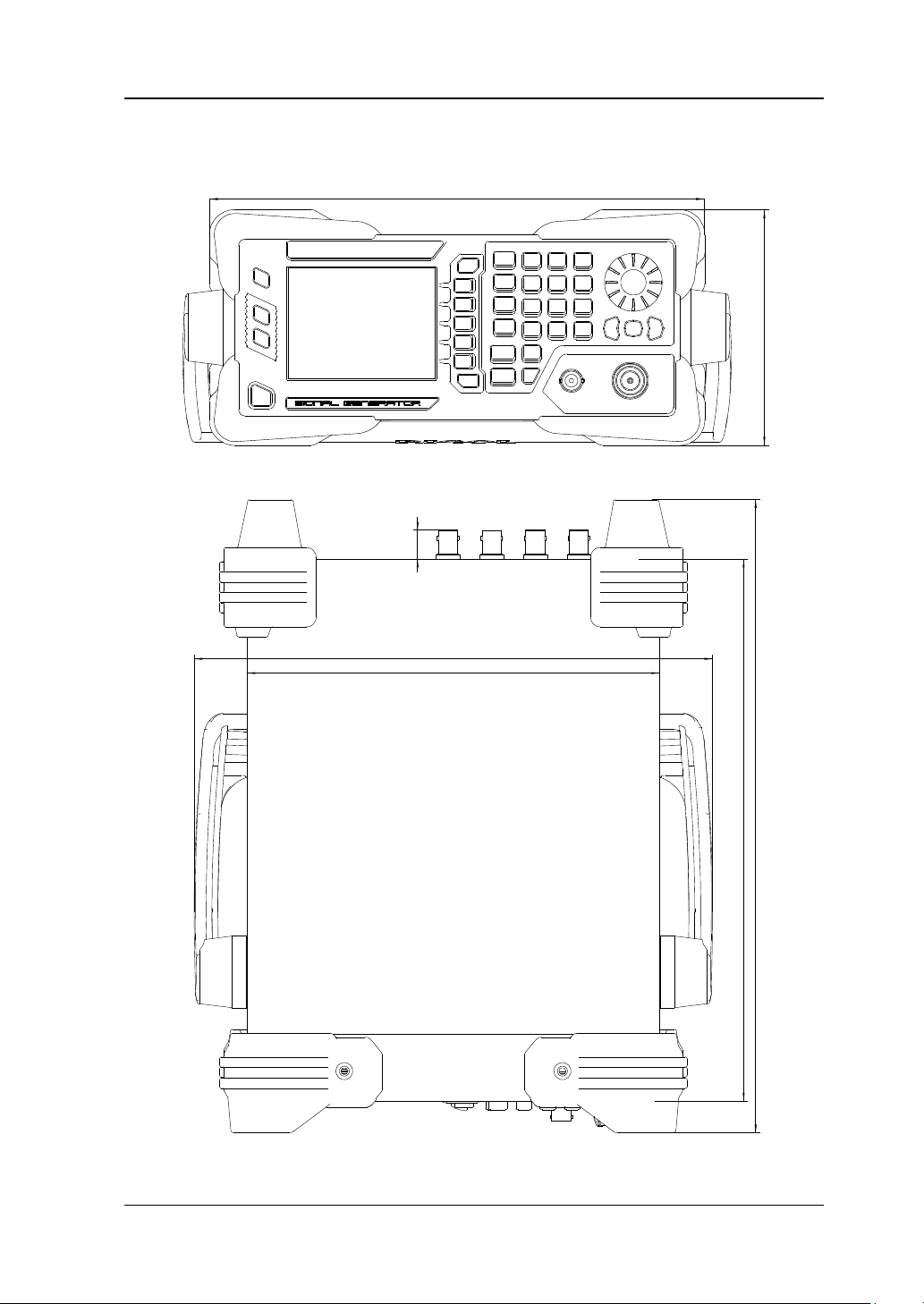
Appearance and Dimensions
Figure 1-1 Front View (unit: mm)
Figure 1-2 Top View (unit: mm)
DSG800 User Guide 1-3
RIGOL Chapter 1 Quick Start
85
.5
1
11
2
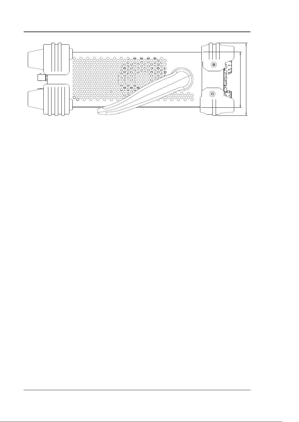
Figure 1-3 Side View (unit: mm)
1-4 DSG800 User Guide
Chapter 1 Quick Start RIGOL
Restore the instrument to the preset state (the factory
3.5 inch TFT high-resolution (320×240) color LCD. The
Interface".
Front Panel Overview
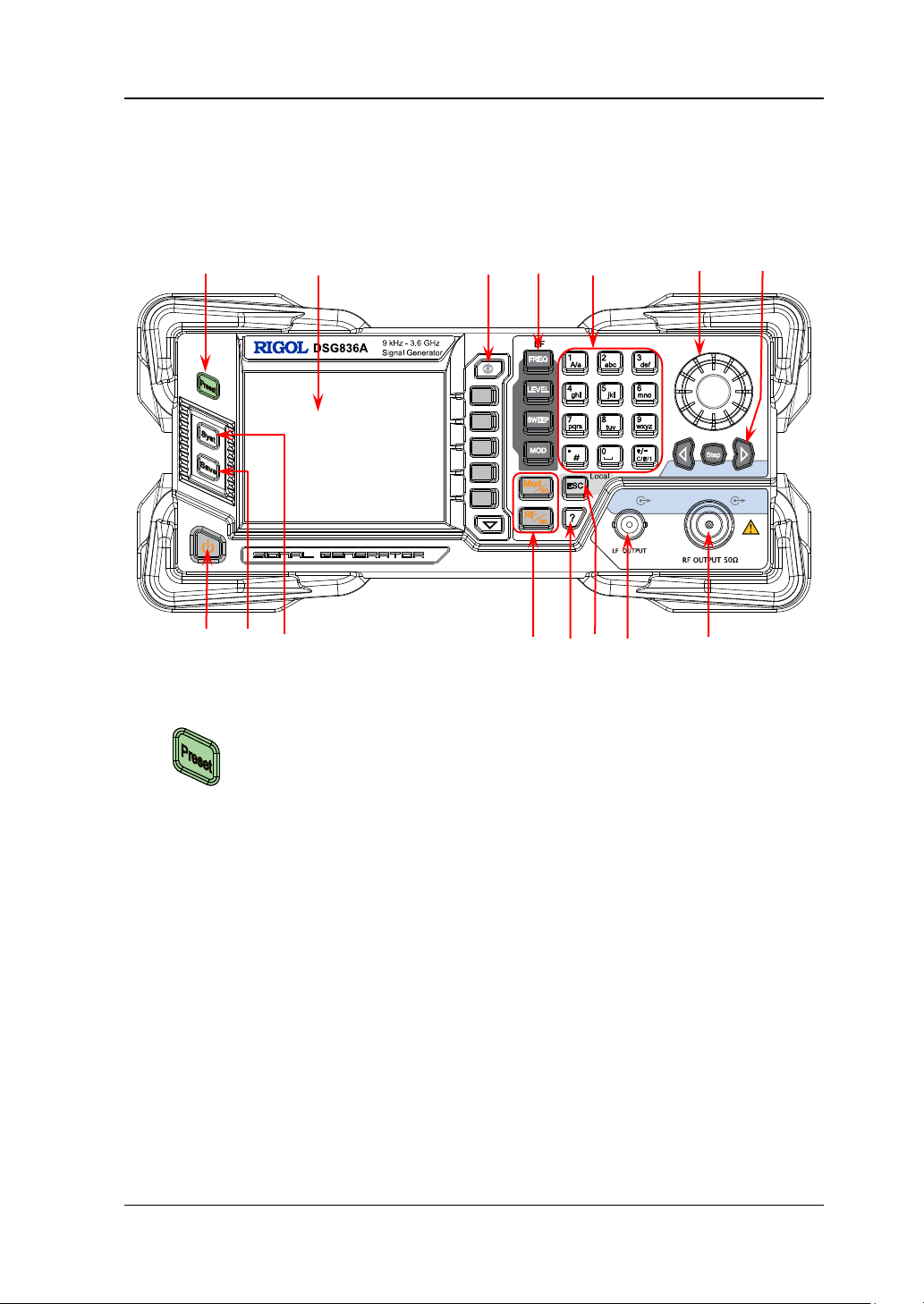
The front panel of DSG800 series RF signal gene rator is as shown in the figure below.
You can click the number in the figure to view the corresponding introduction.
1 2 3 4 5 6 7
8 9 10 11 12 13 14 15
1. Restore to Preset Key
default state or user-stored state). For the detailed
information, refer to "
2. LCD
current settings and state of the instrument can be clearly
displayed. For the detailed information, refer to "
Figure 1-4 Front Panel
Reset".
User
DSG800 User Guide 1-5
RIGOL Chapter 1 Quick Start
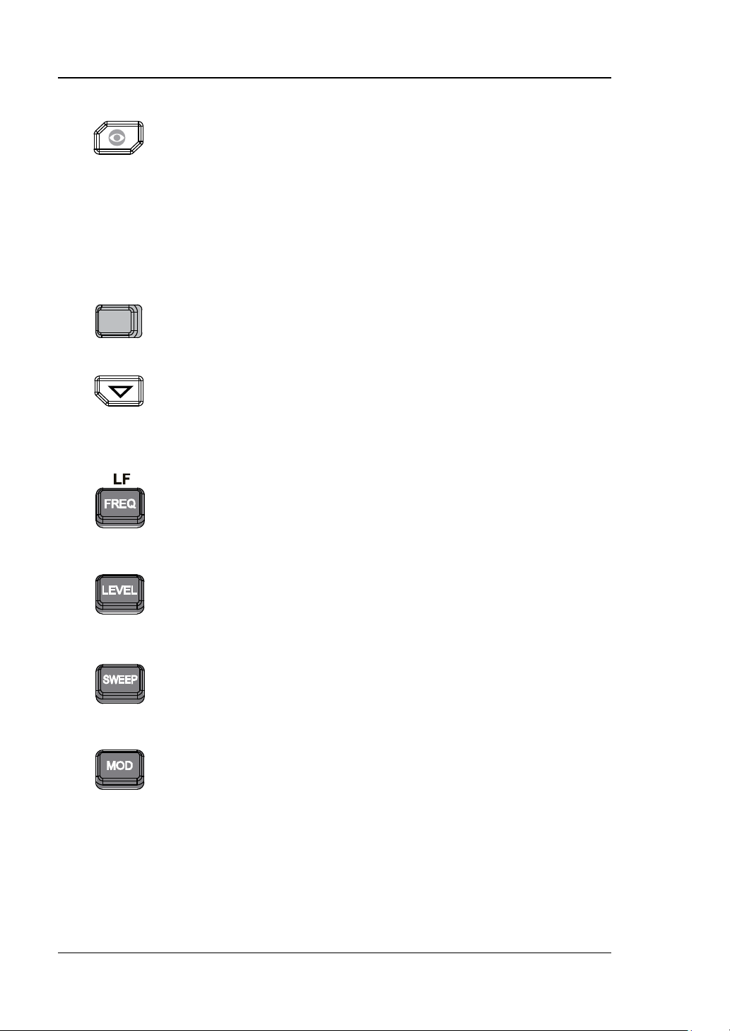
Display switching key. In the menu page of any function,
selected. In addition, y ou can press any f uncti on key to e xit
Menu softkeys correspon ding to the menus displa yed at the
Menu page up/do w n key.
Set the frequency parameters of the RF output signal as
Set the amplitude parameters of the RF output signal and
Set the sweep type, sweep manner, sweep mode a nd etc.
Set the related parameters of amplitude modulation (AM),
refer to "Modulation".
3. Menu Control Keys
4. Function Keys
you can pr ess th is key to open the parameter information
display interface of the current function. At this point, you
can use the knob or arrow keys to switch the parameter
tabs to view the parameter information of different
functions. Pressing this key again will switch to the f unction
menu corresponding to the parameter tab currently
the parameter information display interface.
left of the softkeys respectively. Pressing the softkey will
activate the corresponding menu.
well as the related parameters of LF output. For the
detailed information, refer to "
To Set the Frequency/LF
Parameters".
provide the flatness calibration function. For the detailed
information, refer to "
Parameters
".
To Set the Amplitude
For the detailed information, refer to "Sweep".
frequency modulation (FM), phase modulation (ØM), pulse
modulation and pulse generator as well as I/Q modulation
and I/Q modulation source. For the detailed information,
1-6 DSG800 User Guide
Chapter 1 Quick Start RIGOL
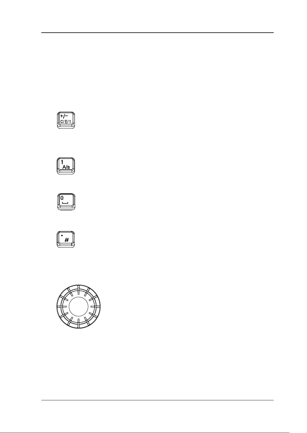
The numeric keyboard supports Chinese characters, English uppercase
The multiplexing keys of the numbers and letters are used to directly input the
Used to switch among Chinese, English and number input
In number input mode, press this key to input 1.
The multiplexing key of 0 and space.
In number input mode, press this key to insert a decimal
In Chinese input mode, this key is invalid.
When setting a parameter, the knob is used to modify the
switch the parameter tabs.
5. Numeric Keyboard
/lowercase characters, numbers and commonly used symbols (include the
decimal point, #, space and positive/negative si gn +/-). It is mainly us ed to edit
the f il e or folder name and set the parameters.
desired numbers or letters.
modes.
When setting a parameter, the input mode is fixed at
number and this ke y is used to in put the sign ("+" or "-") of
the value.
In English input mode, press this key to switch between
uppercase and lowercase letter inputs.
In number input mode, press this key to input 0.
In Chinese or English input mode, press this key to input a
space.
point at the current cursor position.
In English input mode, press this key to input "#".
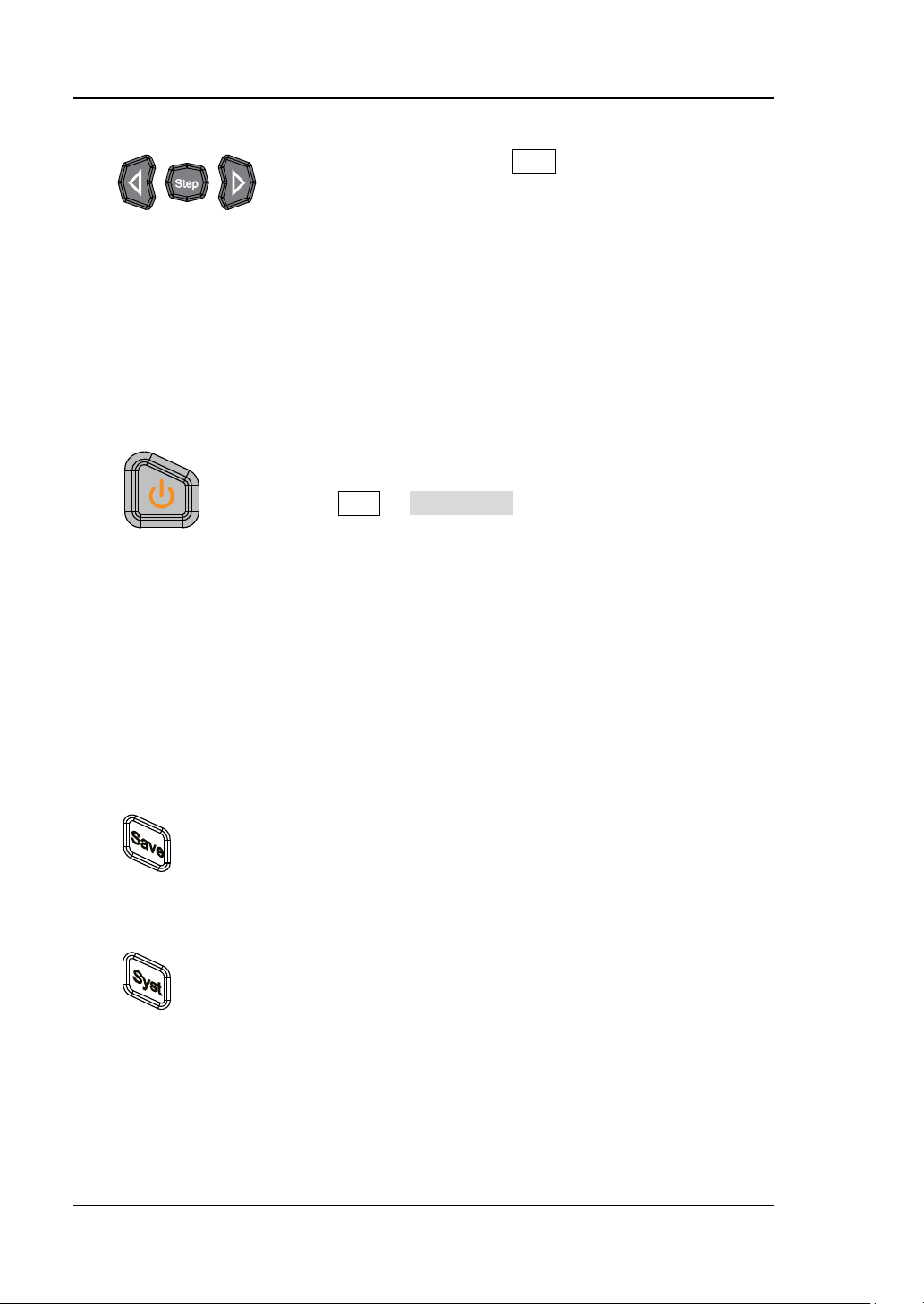
6. Knob
value at the cursor or modify the parameter value at the
current step.
When editing a filename, it is used to select the desired
character.
For the storage function, it is used to select the current
directory or f i l e.
In the parameter inf ormation display inte rface, it is used t o
DSG800 User Guide 1-7
RIGOL Chapter 1 Quick Start
When setting a parameter, Step is used to set the step of
keys are used to switch the parameter tabs.
It is used to turn on or off the RF signal gene rator. You can
due to misoperation.
Store and recall various types of files (such as the
Set the system-related parameters. For the detailed
7. Arrow Keys/Step Key
the parameter currently selected; the arrow keys are used
to enter the parameter editing state and move the cursor
to the specified digit.
For the storage function, the arrow keys are used to
collapse and expand the directory cu rrent ly sele cted .
When editing a filename, the arrow k eys are used to
select the desired character.
In the parameter information display interface, the arrow
8. Power Key
use the following method to enable or disable this key.
Press Syst Pwr Status to sel ect "Default" or "Open".
When "Default" is selected, you need to press this key to
start the instrument after the instrument is powered on.
When "Open" is selected, the instrument will start
automatically after it is powered on.
Besides, this key provides the delayed switching function
(namely, the instrument can be turned on or off only
when you press this key and hold it down for a certain
period of time) to avoid the shut-down of the instrument
9. Store and Recall Key
instrument state). For the detailed information, refer to
"
Store and Recall".
10. Sy stem Setting Key
information, refer to "To Set the System Parameters".
1-8 DSG800 User Guide
Chapter 1 Quick Start RIGOL
Used to turn on or off the RF output.
Used to turn on or off the RF modulation output.
turned off.
To get the help information of any front panel key or
key.
When setting a parameter, this key is used to clear the
exit the current menu and return to the previous menu.
11. Output Control Keys
— Press this key; the backlight of the key and the RF
label in the function status area in the user interface
are illuminated. At this point, the RF output is turned
on and the [RF OUTPUT 50Ω] connector outputs
RF signal according to the current configuration.
— Press this key again; the backlight of the key turns of f
and the RF label in the function status area in the
user interface is grayed out. At this point, the RF
output is turned off.
— When a modulation function (AM, FM, ØM, Pulse Mod
or I/Q Mod) is turned on, press this key; the backlight
of the key and the MOD label in the function status
area in the user interface are illuminated. At this
point, the RF modulation output is turned on and the
[RF OUTPUT 50Ω] connector outputs the
modulated RF signal according to the current
configuration (the backlight of RF/on must be
illuminated).
— Press this key again and the backlight of the key
turns off. At this point, the RF modulation output is
12. Built-in Help Sys te m
menu softkey, press this key and then press the desired
13. Exit Key
number in the editing window and exit the parameter
input state.
When editing a filename, this key is used to clear the
characters in the input bar.
In the keyboard test state, this key is used to exit the
current test state.
When the instrument is working in the remote mode, you
can press this key to return to the local mode.
After you select the next level of menu, this ke y is us ed to
DSG800 User Guide 1-9
RIGOL Chapter 1 Quick Start
When the LF output is turned on, this connector is used to
When the backlight of RF/on is illuminated, this
modulated signal.
CAUTION
To avoid dama ging the ins trument, t he reverse DC v oltage on the
segment.
14. LF O utput Co nnector
output the LF signal.
15. RF Output Connector
connector is used to output the RF signal and RF sweep
signal.
When the backlights of RF/on and Mod/on are both
illuminated, this connector is used to output the RF
RF output connector cannot exceed 50 V and the reverse power
cannot exceed +30 dBm (1W) in the 1 MHz to 3.6 GHz frequency
1-10 DSG800 User Guide
Chapter 1 Quick Start RIGOL
The function of this connector is determined by the
When the pulse modulation source is "Int" and the pulse
set to "Single" or "Train".
Rear Panel Overview
The rear panel of DSG800 series RF signal gener ator is as shown in the figure below.
You can click the number in the f igure to view the corresponding introduction.
1 2 3 4 5
6 7 8 9 10 11 12
Figure 1-5 Rear Panel
1. Pulse Signal Input/Output Connector
current working mode of pulse modulation.
PULSE IN:
When the pulse modulation source is "Ext", this
connector is used to input the external pulse signal.
PULSE OUT:
output is turned on, this connector is used to output the
pulse signal generated by the internal generator. This
output signal is related to the pulse "Mode" and can be
DSG800 User Guide 1-11
RIGOL Chapter 1 Quick Start
When the modulation source of AM or FM/ØM is
When the RF output frequency or amplitude is
stable (namely, the signal is valid).
3.3V
0V
Power-on Time
RF Valid
Configuration
Time
Configuration
Time
RF Valid
… …
V
T
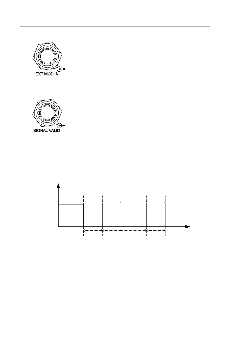
2. External Modulation Input Connector
set to "Ext", this connector is used to input the
external modulating signal.
3. Signal Valid Output Connector
modified, after a certain response and processing
time of the internal circuit of the instrument, the
instrument outputs RF signal with the specified
frequency and amplitude via the RF output
connector at the front panel. During this process,
the [SIGNAL VALID] connector outputs a pulse
sync signal, indicating that the RF output signal is
valid.
— High Level (+3.3 V): indicate that the RF
signal is in configuration.
— Low Level (0 V): indicate that the RF signal is
1-12 DSG800 User Guide
Chapter 1 Quick Start RIGOL
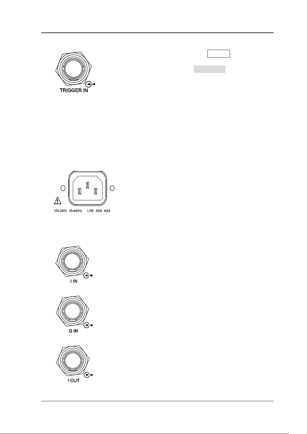
When the trigger mode of SWEEP is “Ext”, this
Power input connector.
When the I/Q modulation source is "Ext", it is
When the I/Q modulation source is "Ext", it is
It is used to output the I (In-Phase) components
4. External Trigger Input Connector
connector is used to input the external trigger
signal. You can press Trig Slope to set the
polarity of the trigger signal to "Pos" or "Neg".
When the trigger mode of I/Q modulation
baseband output is "Ext", this connector is used to
input the external trigger signal.
When the pulse modulatio n source is "Int" an d the
trigger mode is "Ext Trig", it is used to input the
exter nal trigg er signal.
When the pulse modulatio n source is "Int" an d the
trigger mode is "Ext Gate", it is used to input the
exter nal gated signal.
5. Power Input Connector
This RF signal generator can accept 100 V to 240
V, 45 Hz to 440 Hz AC power supplies. The power
consumption of the instrument cannot exceed 60
W.
6. I/Q Modulating Signal Input/Output Connectors (only available for
DSG821A/DSG836A)
used to input the I (In-Phase) baseband signal of
I/Q modulation.
used to input the Q (Qua drature Phase) baseband
signal of I/Q modulation.
of I/Q modulation of the built-in baseband
generator.
DSG800 User Guide 1-13
RIGOL Chapter 1 Quick Start
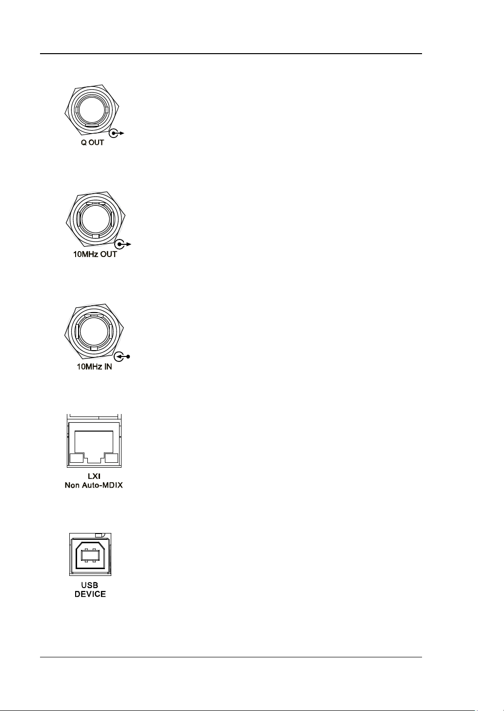
It is used to output the Q (Quadrature Phase)
It is used to output the internal 10 MHz reference
It is used to input the external 10 MHz reference
data sheet of this product.
The instrument complies with LXI Core 2011
The instrument complies with USBTMC class
This interface is used to connect the PC for remote
components of I/Q modulation of the built-in
baseband generator
7. Reference Signal Output Connector
clock signal which is used to synch r onize the
generator with other instruments. For more
information about the specific ations of the clock
signal output from this connector, refer to the data
sheet of this product.
8. Reference Signal Input Connector
clock signal which is used to synchronize the
generator with other instruments. For more
information about the s pecifications of the external
clock signal input from this connector, refer to the
9. LAN
Device standard. It support s WebSer ve r, Socket
and other remote control modes.
This interface is used to connect the RF signal
generator to the PC or network f or remote control.
10. USB DEVICE
protocol.
control.
1-14 DSG800 User Guide
Chapter 1 Quick Start RIGOL
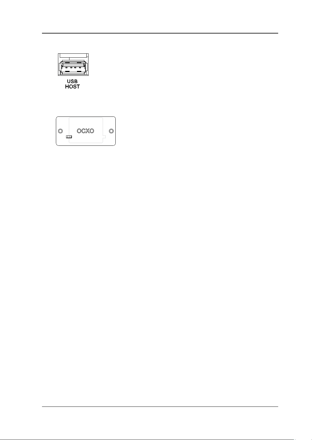
This interface is used to connect the USB storage
OCXO is an oven controlled crystal oscillator. It is
please refer to the data sheet of this product.
11. USB HOST
device to update the system or store the system
states and etc.
12. OCXO (Option OCXO-B08)
a frequency reference source with higher
temperature stability.
Note: Sixty minutes of warm-up is required for
the OCXO to reach its rated frequency.
For the ordering information of this option,
DSG800 User Guide 1-15
RIGOL Chapter 1 Quick Start
CAUTION
To Use DSG800 for the First Time
To Connect the Power Supply
Please connect the RF signal generator to AC power supply using the power cable
supplied in the accessories. This RF signal generator can accept 100 V to 240 V, 45
HZ to 440 Hz AC power supplies. The power consumption of the instrument cannot
exceed 60 W. When the RF signal generator is connected to AC power su pply via thi s
connector, the instrument selects the correct voltage range automatically and users
do not need to select the voltage range manually.
To avoid elec t ric shock, use the standard power cable.
Power-on Inspection
After the power supply is correctly connected, press the power key
panel to t urn on the RF signal generator. During the start-up, the instrument
performs initialization and self-test. After that, the instrument enters the default
interface.
at the front
To Set the System Language
DSG800 series RF signal generator supports multiple system languages. You can
press Syst Language to switch the system language.
1-16 DSG800 User Guide
Chapter 1 Quick Start RIGOL
User Interface
The user interface of DS G800 series RF signal gener ator is shown in the figure below.
1 2 3 4
5 6
Figure 1-6 User Interface
1. Frequency Area
Display the current frequency settings of the RF signal generat or.
—
—
—
—
—
2. Amplitude Area
Display the current level settings of the RF signal generator.
—
—
—
—
: continuous sweep label. It is displayed when the sweep manner is
"Freq" or "Freq & Lev" and the sweep mode is "Cont".
: single sweep label. It is displayed when the sweep manner is "Freq"
or "Freq & Lev" and the sweep mode is "Single".
: forward sweep label. It is displayed when the sweep manner is "Freq"
or "Freq & Lev" and the sweep direction is "Fwd".
: downward sweep label. It is displayed when the sweep manner is
"Freq" or "Freq & Lev" and the sweep direction is "Down".
: frequency sweep progress bar. It is displayed when the
sweep manner is "Freq" or "Freq & Lev".
: displayed when the flatness calibration is turned "On".
: continuous sweep label. It is displayed when the sweep manner is
"Level" or "Freq & Lev" and the sweep mode is "Cont".
: single sweep label. It is displayed when the sweep manner is "Level"
or "Freq & Lev" and the sweep mode is "Single".
: forward sweep label. It is displayed when the sweep manner is
DSG800 User Guide 1-17
RIGOL Chapter 1 Quick Start
Icon
Explanation
Icon
Explanation
The RF output is not turned
selected.
The LF output is not
waveform is selected.
The RF output is not turned
manner is selected.
The LF output is not
waveform is selected.
The RF output is turned on
selected.
The LF output is turned
selected.
The RF output is turned on
manner is selected.
The LF output is turned
is selected.
"Level" or "Freq & Lev" and the sweep direction is "Fwd".
—
: downward sweep label. It is displayed when the sweep manner is
"Level" or "Freq & Lev" and the sweep direction is "Down".
—
: amplitude sweep progress bar. It is displayed when the
sweep manner is "Level" or "Freq & Lev".
3. Status Bar
Indicate the current system states of the RF signal generator.
—
—
—
—
: the RF signal generator is working in the remote control mode.
: the RF signal generator is working in the local operation mode.
: displayed when a USB storage device is detected.
: displayed when the instrument parameter information interface is
opened.
4. Menu Display Area
The menu items displayed i n this a rea correspond to the softkeys at the right of
the screen respectively. Pressing any softkey can enable the corresponding
menu function.
5. Message Display Area
Display the operation error messages and prompt messages. You can press
Syst Information System Msg to view the messages. When multiple
messages are generated, you can use the arrow keys or knob to select the
desired message.
6. Function Status Area
Display the current states of the functio ns of the RF signal gene rator. The status
icons that might be displayed in the function status area are as shown in the
table below.
on and no sweep manne r is
on and only a single sweep
and no sweep manner is
and only a single sweep
1-18 DSG800 User Guide
turned on and Sine
turned on and Square
on and Sine waveform is
on and Square waveform

Chapter 1 Quick Start RIGOL
The RF modulation output
AM is turned on.
The RF modulation
AM is turned on.
The RF modulation output
FM is turned on.
The RF modulation
FM is turned on.
The RF modulation output
ØM is turned on.
The RF modulation
ØM is turned on.
The RF modulation output
Pulse is turned on.
The RF modulation
Pulse is turned on.
The RF modulation output
is turned on.
The RF modulation
IQ is turned on.
The RF modulation output
FM are turned on.
The RF modulation
and FM are turned on.
The RF modulation output
ØM are turned on.
The RF modulation
and ØM are turned on.
The RF modulation output
Pulse are turned on.
The RF modulation
and Pulse are turned on.
The RF modulation output
Pulse are turned on.
The RF modulation
and Pulse are turned on.
The RF modulation output
are turned on.
The RF modulation
and IQ are turned on.
The RF modulation output
Pulse are turned on.
The RF modulation
and Pulse are turned on.
The RF modulation output
are turned on.
The RF modulation
and IQ are turned on.
The RF modulation output
Pulse are turned on.
The RF modulation
and Pulse are turned on.
The RF modulation
on.
is not turned on and only
is not turned on and only
is not turned on and only
is not turned on and only
is not turned on and onl y IQ
is not turned on; AM and
is not turned on; AM and
is not turned on; AM and
output is turned on and
output is turned on and
output is turned on and
output is turned on and
output is turned on and
output is turned on; AM
output is turned on; AM
output is turned on; AM
DSG800 User Guide 1-19
is not turned on; FM and
is not turned on; FM and IQ
is not turned on; ØM and
is not turned on; ØM an d IQ
is not turned on; IQ and
The RF modulation output
is not turned on; AM, FM
and Pulse are turned on.
The RF modulation output
is not turned on; AM, ØM
output is turned on; FM
output is turned on; FM
output is turned on; ØM
output is turned on; ØM
output is turned on; IQ
output is turned on; AM,
FM and Pulse are turned
The RF modulation
output is turned on; AM,

RIGOL Chapter 1 Quick Start
and Pulse are turned on.
ØM and Pulse are turned
The RF modulation
on.
The RF modulation
on.
The RF modulation output
is turned on.
on.
The RF modulation output
is not turned on; FM, IQ
and Pulse are turned on.
The RF modulation output
is not turned on; ØM, IQ
and Pulse are turned on.
is not turned on and none
of the modulation functions
-- --
output is turned on; FM,
IQ and Pulse are turned
output is turned on; ØM,
IQ and Pulse are turned
Tip: Press MOD and the AM/FM/ØM/PUL/IQ modulation icons are displayed in
the function status area. If a modulation function is turned on (or off), the
corresponding icon will be illuminated (or grayed out).
1-20 DSG800 User Guide

Chapter 1 Quick Start RIGOL
To Use the Built-in Help System
The DSG800 built-in help syste m p rovides the help information of all the function
keys and menu softkeys at the front panel. Users can view the help information of
any key when operating the instrument.
1. Acquire the built-in help information
Press ? and press the desired function key or menu softkey; the help
information of the key will be displayed in the instrument interface.
2. Page up/down
When the help inf ormation is display ed in mult iple pages, you can use the arrow
keys or knob to switch the help information page.
3. Turn off the current help information
When help information is displayed in the instrument inte rface, pressin g any ke y
(except the arrow keys and knob) at the front panel will turn off the help
information currently display ed.
4. Acquire the help information of a menu softkey
Press ? and the prompt message about how to acquire the help information
is displayed in the instrument interface. Then, press the desired menu softkey
and the help information of the menu item cor responding to this men u softkey is
displayed in the instrument interface.
5. Acquire the help information of any function key
Press ? and the prompt message about how to acquire the help information
is displayed in the instrument interface. Then, press the desired function key
and the help inf ormation of the fun ction of the key is displaye d in the inst rument
interface.
DSG800 User Guide 1-21


Chapter 2 Front Panel Operations RIGOL
Chapter 2 Front Panel Operations
This chapter introduces each function key at the front panel as well as the menu
functions under it in details.
The topics of this chapter:
To Set the Frequency/LF Parameters
To Set the Amplitude Parameters
Sweep
Modulation
Store and Recall
To Set the System Parameters
DSG800 User Guide 2-1

RIGOL Chapter 2 Front Panel Operations
To Set the Frequency/LF Parameters
Frequency
Set the RF output frequency.
Press FREQ, use the numeric keyboard to input the frequency value and select t he
desired unit from the pop-up unit menu.
The frequency units available are GHz, MHz, kHz and Hz.
You can press Backspace to delete the number at the lef t of the cursor.
You can press the left/right ar row key to enter the parameter editing state and
move the cu rsor to the specified digit; then, rotate the knob to modify the value.
After the frequency is set, you can rotate the knob to modify the frequency at
the current step.
You can press FREQ and then press Step to set the step.
LF Output
LF output denotes the output of the low-frequency signal generated by the internal
generator of the RF signal generator. The LF output can be one of the two commonly
used waveforms (sine or square). You can set the frequ ency and amplitude of the
low-frequency signal.
Press FREQ LF to enter the LF output parameter setting menu.
To Turn on the LF Output
Press FREQ LF Switch to turn "On" or "Off" the LF output. When "On" is
selected, the LF label and the label of the waveform currently selected (Sine or
Square) in the function status area of the user interface are illuminate d. At this point,
the [LF OUTPUT] connector (as shown in the figure below) outputs the LF signal
according to the current configuration.
2-2 DSG800 User Guide

Chapter 2 Front Panel Operations RIGOL
Explanation
The settable range of square frequency is from 0 Hz to 20 kHz.
To Select the LF Waveform
Press FREQ LF Waveform to set the waveform of the LF output signal to
"Sine" or "Square". The default is "Sine".
To Set the LF Amplitude
Press FREQ LF Level to set the amplitude of the LF signal.
Use the numeric keyboard to input the amplitude value and select the desired
unit from the pop-up unit menu.
The amplitude units available are V, mV, uV, nV and dBm.
You can press Backspace to del ete the number at the lef t of the cursor.
You can press the left/right arro w key to enter the parameter editing state and
move the cursor to the specified digit; then, rotate the knob to modify the v alue.
You can also rotate the knob to modify the amplitude at the current step.
You can press Step to set the step.
The settable ranges of the amplitudes of sine an d sq uare are both from 0 V to 3
V. Note that when the frequency is 0 Hz, the LF output is DC signal and the
settable range of the amplitude is from -3 V to 3 V.
To Set the LF Frequency
Press FREQ LF Freq to set the frequency of the LF signal.
Use the numeric keyboard to input the frequency value and select the desired
unit from the pop-up unit menu.
The frequency units available are GHz, MHz, kHz and Hz.
You can press Backspace to del ete the number at the lef t of the cursor.
You can press the left/right ar row key to enter the parameter editing sta te and
move the cursor to the specified digit; then, rotate the knob to modify the v alue.
After the frequency is set, you can rotate the knob to modify the frequency at
the current step.
You can press Step to se t the step.
The settable range of sine frequency is from 0 Hz to 200 kHz.
DSG800 User Guide 2-3

RIGOL Chapter 2 Front Panel Operations
To Set the Amplitude Parameters
Amplitude
Set the RF output amplitude.
Press LEVEL, use the numeric keyboard t o input the amplitude value and select the
desired unit from the pop-up unit menu.
The amplitude units available are dBm, -dBm, mV, uV and nV.
You can press Backspace to del ete the number at the lef t of the cursor.
You can press the left/right arro w key to enter the parameter editing state and
move the cursor to the specified digit; then, rotate the knob to modify the v alue.
You can also rotate the knob to modify the amplitude at the current step.
You can press LEVEL and then press Step to set the step.
Flatness Calibration
The flatness calibration function can adjust the RF output amplitudes corresp onding
to the frequency points within the frequenc y r ange o f the inst rument to compensate
for the external loss caused by the cables, switches or other devices. You can load
the flatness calibration lists st ored in the i nternal or external me mory to DSG8 00 and
view the list contents.
1. Set the flatness calibration status
Press LEVEL Flatness Switch to turn "On" or "Off" the flatness
calibration function. When the flatness calibration function is turned on, the UF
status label is displayed in the amplitude area of the user interface.
2. Flatness c al ibration lis t
Press LEVEL Flatness Cal List to enter the flatness calib ration list men u.
Load a li s t
Press Load to open the store and recall interface. At this point, you can
select and read the flatness calibration list files stored. For the detailed
operations, refer to "
directory of the file loaded is displayed in View.
The format of the calibration list file loaded is as shown in the table below.
Note that while you edit the value in t he flatness cali bration lis t, if no unit i s
added, then the default frequency unit is mHz and the default amplitude
unit is dB.
Store and Recall". After a list is loaded, the storage
2-4 DSG800 User Guide

Chapter 2 Front Panel Operations RIGOL
SN
Freq
Level
[1]
1
207.854 000 00 MHz
-70.50 dB
2
304.000 000 00 MHz
7.45 dB
3
800.000 000 00 MHz
-17.80 dB
[1]
Note
frequency point, only the actual output amplitude will be affected and the amplitude
display value will not change.
: Amplitude calibration value. When calibrating the amplitude of the current
View the list
You can press View to view the information of the flatness calibration list
currently loaded. Pressing an y ke y (e xcept t he a rrow k eys and knob) at the
front panel will return to the flatness calibration list menu.
Note: This menu is only valid after a list file is loaded.
Amplitude Uni t
Set the unit of the RF output amplitude.
Press LEVEL Leve l Unit and select the desired unit from the pop-up unit menu.
The output amplitude unit s available are dBm, dBmV, dBuV , V olts and W atts. Wh erein,
dBm, dBmV and dBuV are logarithmic units; Volts and Watts are linear units. The
default is dBm.
DSG800 User Guide 2-5

RIGOL Chapter 2 Front Panel Operations
Sweep
When the sweep function is turned on, the RF signal generator outputs RF sweep
signal from the [RF OUTPUT 50Ω] connector (as sh own in the figure below) a t the
front panel (at this point, the RF output should be turned on).
Sweep Manner
DSG800 provides three sweep manners ("Freq", "Level" and "Freq & Lev"). The
sweep function is turned on when any of the sweep manners is selected and the
Sweep label in the functio n status area of the user interface is illuminated. By default,
the sweep function is turned off.
Press SWEEP Sweep to select the desired sweep manner.
Off: the default state. Turn off the sweep function.
Freq: turn on the frequency sweep function. At this point, the frequency sweep
progress bar is displayed in the frequency area in the user interface.
Level: turn on the a mplitude swee p function. At this point , the a mplitude swe e p
progress bar is displayed in the amplitude area in the user interface.
Freq & Lev: turn on the frequency and amplitude sweep functions at the same
time. At this point, the frequency and amplitude sweep progress bars are
displayed in the frequency and amplitude areas in the user interface
respectively.
Sweep Direction
Press SWEEP and use the menu page up/down key
the menu; then, press Direct to select "Fwd" or "Down" and the default is "Fwd".
Fwd: the RF signal generator sweeps from the start frequency or start level to
the stop frequency or stop level. The progress bars in the frequency area and
amplitude area in the user interface sweep from left to right.
Down: the RF signal generator sweeps from the stop frequency or stop level to
the start frequency or start level. The progress bars in the frequency area and
amplitude area in the user interface sweep from right to left.
to open the 3/3 page of
2-6 DSG800 User Guide

Chapter 2 Front Panel Operations RIGOL
SN
Freq
Level
[1]
Time
[2]
1
2.000 000 000 10 GHz
-10.00 dBm
500.00 ms
2
1.994 152 687 00 GHz
-50.00 dBm
500.00 ms
3
1.888 000 000 00 GHz
-60.85 dBm
500.00 ms
Sweep Type
DSG800 provides two sweep types ("List" and "Step") and the default is "Step".
List Sweep
1. Select the list sweep mode
Press SWEEP Type to select "List". At this point, the RF signal generator
sweeps according to the sweep list currently loaded.
2. Sweep list
Press SWEEP and use the page up /down key
menu; then, press Lis t Swp to enter the sweep list menu.
Load a li s t
Press Load to open the store and recall interface. At this point, you can
select and read the sweep list files stored. For the detailed operations, refer
Store and Recall". After a list is loaded, the storage directory of the
to "
file loaded is displayed in View.
The format of the swee p list file loaded is as shown in the ta ble below . Note
that when you e dit the value in the swe ep list, the unit must be added. If no
unit is added, then you may fail to load the list.
to open the 2/3 pa ge of the
View the list
DSG800 User Guide 2-7
[1]
Note
Note
: The amplitude corresponding to the frequency point set.
[2]
: The duration of a sweep step.
You can press View to view the information of the sweep list currently
loaded. Pressing any key (except the arrow keys and knob) at the front
panel will return to the sweep list menu.
Note: This menu is only valid after a list file is loaded.

RIGOL Chapter 2 Front Panel Operations
Explanation
Freq" or "S t op Freq".
Step Sweep
1. Select the step sweep mode
Press SWEEP Type to select "Step". At this point, the RF signal generator
performs step sweep according to the current settings.
2. Set the sweep parameters
Press SWEEP and use the menu page up/d o w n key
of the menu; then, press Step Swp to set the sweep parameters, such as the
start frequency, stop frequency, start level, stop level and number of sweep
points.
Start Frequency
Press Start Freq, use the numeric keyboard to input the start frequency
value and select the desi red unit f rom the po p-up unit menu. You can press
Backspace to delete the number at the left of the cursor.
Stop Frequency
Press Stop Freq, use the numeric keyboard to input the stop frequency
value and select the desi red unit f rom the po p-up unit menu. You can press
Backspace to delete the number at the left of the cursor.
to open the 2/3 page
The start frequency and stop frequency are the frequency upper and
lower limits of frequency sweep respectively.
When the sweep direction is forward, the RF signal generator
sweeps from the start frequency to the stop frequency.
When the sweep direction is downward, the RF signal generator
sweeps from the stop frequency to the start frequency.
When the "Start Freq" or "Stop Freq" is modified, the RF signal
generator will restart the sweep and output from the specified "Start
Start Level
Press Start Lev, use the numeric keyboard to input the start level value
and select the desired unit from the pop-up unit me nu. You can press
Backspace to delete the number at the left of the cursor.
Stop Level
Press Stop Lev, use the numeri c keyboar d to input t he stop leve l value and
select the desired unit from the pop-up unit menu. You can press
Backspace to delete the number at the left of the cursor.
2-8 DSG800 User Guide

Chapter 2 Front Panel Operations RIGOL
Explanation
The start level and stop lev el are the a mplitude upper an d lower limits of
Lev".
amplitude sweep respectively.
When the sweep direction is forward, the RF signal generator
sweeps from the start level to the stop level.
When the sweep direction is downward, the RF signal generator
sweeps from the stop level to the start level.
When the "Start Lev" or "Stop Lev" is modified, the RF signal generator
will restart the sweep and output from the spe cified "Start Lev" or "Stop
Number of Sweep Points
Press Points, use the numeric keyboard to input the number of sweep
points and then press Enter. You can press Backspace to delete the
number at the left of the cursor.
Dwell Time
The dwell time denotes the duration of a sweep step.
Press Dwell Time, use the numeric keyboard to input the time value and
select the desired unit from the pop-up unit menu. You can press
Backspace to delete the number at the left of the cursor.
Sweep Space
The sweep space denotes the mode in which the instrument changes from
one frequency or amplitude to another within one step.
Press Swp Space to select "Log" or "Lin" sweep space. No te that level
sweep only supports "Lin" sweep space.
Sweep Shape
The sweep shape denotes the cycle mode of multiple sweeps.
Press Shape to select "Ramp" or "Triangle" sweep shape. When the sweep
direction is "Fwd", the "Ramp" and "Triangle" sweep shapes are as shown in
the figure below.
DSG800 User Guide 2-9

RIGOL Chapter 2 Front Panel Operations
F/L
T
Start Frequency
/Start Level
Start Frequency
/Start Level
Ramp
Triangle
Stop Frequency
/Stop Level
Stop Frequency
/Stop Level
Sweep Mode
Press SWEEP Mode to select "Cont" or "Single" sweep and the default is "Cont".
Cont: when continuous sweep is selected, the continuous sweep label is
displayed in the frequency or amplitude area in the user interface. When the
trigger condition is met, the instrument sweeps continuously according to the
current setting.
Single: when single sweep is selected, the single sw e ep label is displayed in the
frequency or amplitude are a in t he use r int erf ace. When the trigger condition is
met, the instrument performs a single sweep according to the current setting
and then stops.
Single Sweep
If the current sweep mode is "Cont", press Single to switch the sweep mode to
"Single" and the instrument will perform a single sweep if the trigger condition is
Ramp: the sweep period always starts from the start frequency or start level
to the stop frequency or stop level and the sweep sequence is similar to a
ramp waveform .
Triangle: the sweep period always starts from the start frequency or start
level to the stop frequency or stop level and then returns back to the start
frequency or start level. The sweep sequence is similar to a triangle
waveform.
2-10 DSG800 User Guide

Chapter 2 Front Panel Operations RIGOL
met.
If the current sweep mode is "Single", press Single and the instrument will perform
a single sweep if the trigger condition is met.
To Reset the Sweep
If the current sweep direction is "Fwd", press Reset Swp, the instrument stops the
current sweep and restarts the sweep from the start frequency or start level.
If the current sweep di rection is "Down", press Reset Swp, the instrument st ops the
current sweep and restarts the sweep from the stop frequency or stop level.
Trigger Mode
1. Trigger Mode
Select the trigger mode of the whole sweep period.
Press SWEEP and use the menu page up/dow n key
of the menu; then, press Trig Mode to select "Auto", "Key", "Bus" or "Ext"
trigger.
Note: The following descriptions are valid when the trigger mode of each sweep
point in the sweep period is met.
Auto Trigger
The default mode is auto. If the sweep mode is set to "Cont", the
instrument will start sweeping once a sweep manner is selected. If the
sweep mode is set to "Single", you need to press Single to meet the single
sweep condition; after that, the instrument will start a sweep and then
stops.
Key Trigger
When "Key" trigger is selected, if the sweep mode is set to "Cont", th e
instrument starts a sweep each time Key Trig is pressed; if the sweep
mode is set to "Single", you need to press Single to meet the single sweep
condition and after that, the instrument starts a sweep and then stops ea ch
time Key Trig is pressed.
Bus Trigger
When "Bus" trigger is selected, if the sweep mode is set to "Cont", the
instrument starts a sweep each time the "*TRG" command is sent; if the
sweep mode is set to "Single", you need to press Single to meet the single
sweep condit ion and after t hat, the instrument starts a sweep and then
to open the 2/ 3 page
DSG800 User Guide 2-11

RIGOL Chapter 2 Front Panel Operations
stops each time the "*TRG" command is sent.
External Trigger
In external trigger, the RF signal generator receives the trigger signal input
from th e [TRIGGER IN] connector (as show n in the figure on the next
page) at the rear panel. If the sweep mode is set to "Cont", the inst ru ment
starts a sweep each time a TTL pulse signal with the specified polarity is
received. If the sweep mode is set to "Single", you need to press Single to
meet the single sweep condition; after that, the instrument starts a sweep
and then stops each time a TTL pulse signal with the specified polarity is
received.
To specify the polarity of the TTL pulse signal, press Trig Slope to select
"Pos" or "Neg" and the default is "Pos".
2. Point Trigge r Mo d e
Select the trigger mode of each sweep point in a sweep period.
Press SWEEP and use the menu page up/down k ey
to open the 2 /3 page
of the menu; then, press Point Trig to select "Auto", "Key", "Bus" or "Ext"
trigger.
Note: The following descriptions are valid when the trigger mode of the
corresponding sweep period is met.
Auto Trigger
The default mode is auto. If the sweep mode is set to "Cont", the
instrument will start sweeping each sweep point continuously within a
sweep period once a sweep manner is selected. If the sweep mode is set t o
"Single", you need to press Single to meet the single sweep condition;
after that, the instrument starts to sweep and then stops after the sweep
period expires.
Key Trigger
When "Key" trigger is selected, if the sweep mode is set to "Cont", th e
instrument starts to sweep a point each time Key Trig is pressed; if the
sweep mode is set to "Single", you need to press Single to meet the single
sweep condition and after that, the instrument starts to sweep a point and
then stops after the sweep period expires each time Key Trig is pressed.
2-12 DSG800 User Guide

Chapter 2 Front Panel Operations RIGOL
Explanation
When executing the s weep o perat ion, the priorit y order of the con ditions is
Point Trigger Mode. For example, when
instrument starts to sweep.
Bus Trigger
When "Bus" trigger is selected, if the sweep mode is set to "Cont", the
instrument starts to sweep a point each time the "*TRG" command is sent;
if the sweep mode is set to "Single", you need to press Single to meet the
single sweep condition and after that, the instrument starts to sweep a
point and then stops after the sweep period expires each time the "*TRG"
command is sent.
External Trigger
In externa l tri gge r m ode , the RF si gnal gene r ator re ceiv es t he tri gger s igna l
input from the [TRIGGER IN] connector (as shown in the figure below) at
the rear panel. If the sweep mode is set to "Cont", the instrument starts to
sweep a point each time a TTL pulse signal with the specified polarity is
received. If the sweep mode is set to "Single", you need to press Single to
meet the single sweep condition; aft er that, the instrument starts to sweep
a point and then stops after the sweep period expires each time a TTL pulse
signal with the specified polarity is received.
To specify the polarity of the TTL pulse signal, press Trig Slope to select
"Pos" or "Neg" and the default is "Pos".
Single Sweep Trigger Mode
both the trigger mode and point trigger mode are set to "Key" trigger:
In "Cont" sweep mode, you need to press Key Trig to meet the
trigger mode of the whole period and then press Key Trig again to
meet the trigger mode of the points within the swee p period; then, the
instrument starts to sweep.
In "Single" sweep mode, you need to press Single to meet the single
sweep condition and then press Key Trig twice to meet the sweep
period trigger mode and point trigger mode respectively; then, the
DSG800 User Guide 2-13

RIGOL Chapter 2 Front Panel Operations
Modulation
Amplitude Modulation (AM)
During amplitude modulation (AM), the modulating signal changes the amplitude of
the RF carrier waveform linearly.
Press MOD AM to enter the amplitude modulation parameter setting menu.
To Turn on Amplitude Modulation
Press Switch to select "On" or "Off".
On: turn on the AM fu nction. The AM la bel in the fun ction status a rea in the use r
interface is illuminated.
Off: turn off the AM function and this is the default state.
Note: If a sweep manner is selected and the step sweep time is lower than 30 ms,
"You can turn on the AM when sweep time is greater than 30ms" will be displayed in
the user interface when amplitude modulation is turned on.
To Select the Modulation Source
Press Source to select "Int" or "Ext" modulation source.
1. Internal So u r c e
When "Int" is selected, the inte rnal modulation s ource is turne d on. At this point,
the instrument provides the modulating signal and you can set the modulation
frequency and modulati on waveform of the modulating signal.
2. External Source
When "Ext" is selected, Freq and Waveform are grayed out and disabled. The
RF signal gen erat or receives the external modulat ing signal input f rom the [EXT
MOD IN] connector (as shown in the figure below) at the rear panel. This
modulating signal can be any waveform.
Note: The input amplitude of the external modulating signal cannot exceed
+/-3 V (HighZ). To ensure the modulation performance, the input amplitude of
the external modulating signal sh ould be less than 1 Vpp.
2-14 DSG800 User Guide

Chapter 2 Front Panel Operations RIGOL
a
m
sb
ΔP
asb
mΔP lg206 −=
To Set the Modulation Depth
The modulation depth denotes the extent of output amplitude variation and is
expressed as a percentage. The range of AM modulation depth is from 0 % to 1 00%.
Press Depth to set the AM modulation depth.
1. When "Int" modulation source is selected
The AM modulation depth (
) and the amplitude difference (
) between
the carrier and sidebands satisfy the following relation.
When the modulation depth is 0%, the instrument outputs a carrier signal
with a single frequency point.
The greater the modulation depth is, the smaller the difference between the
output amplitude and carrier amplitude will be.
2. When "Ext" modulation source is selected
100% modulation depth refers to the modulation depth corresponding to 1
Vpp input amplitude of the external modulation source.
When the input amplitude of the external modulation source is 0.5 Vpp, the
modulation depth actually measured is 50%.
To Select the Modulation Waveform
Press Source to select "Int" modulation sour ce; press Waveform to select "Sine" or
"Square" and the default is "Sine".
Note: When "Ext" modulation source is selected, this menu is grayed out and
disabled.
To Set the Modulation Frequency
Press Source to s elect "Int" modulation source; press Freq to set the modulation
frequency.
Use the numeric keyboard or knob to input the desired frequency value.
For sine waveforms, the range of the modulation frequency is from 10 Hz to 100
kHz.
For square waveforms, the range of the modulation frequency is from 10 Hz to
20 kHz.
Note: When "Ext" modulation source is selected, this menu is grayed out and
disabled.
DSG800 User Guide 2-15

RIGOL Chapter 2 Front Panel Operations
External Coupling
Press EXT Coup to s elect "AC" or "DC" coupling and the default is "AC".
When "AC" is selected: the DC c omponents of the external si gnal input f rom the
[EXT MOD IN] connector at the rear panel of the instrument will be blocked
and the AC components can pass through the connector.The extern al
modulation input port is similar to a high-pass filter which low cutoff frequency
is less than 5 Hz.
When "DC" is selected: all the AC components and DC component s of the
external input signal can pass through the conne ctor.
Note: When "Int" modulation source is selected, this menu is grayed out and
disabled.
Input Impedance
Press Impedance to select "50ohm", "600ohm" or "100kohm ". You can set the
impedance of the [EXT MOD IN] input channel.
Note: When "Int" modulation source is selected, this menu is grayed out and
disabled.
2-16 DSG800 User Guide

Chapter 2 Front Panel Operations RIGOL
Frequency Modulation (FM)
During frequency modulation (FM), the modulating signal changes the frequency of
the RF carrier wa v ef or m.
Press MOD FM/ØM to enter the frequency/phase modulation parameter setting
menu.
To Turn on Frequency Modulation
Press FM/ØM to select "FM" and then press Switch to select "On" or "Off".
On: turn on the FM function. The FM la bel in t he func tion status a rea in t he use r
interface is illuminated.
Off: turn off the FM function and this is the default state.
Note: The frequency modulation and phase modulation cannot be turned on at the
same time. In addition, if a sweep manner is selected and the step sweep time is
lower than 200 ms, "You can turn on the FM or ØM when sweep time is g reate r than
200ms" will be displayed in the user interface w hen frequency modulation is turned
on.
To Select the Modulation Source
Press Source to s elect "Int" or "Ext" modulation source.
1. Internal So u r c e
When "Int" is selected, the inte rnal modulation s ource is turne d on. At this point,
the instrument provides the modulating signal and you can set the modulation
rate and modulation waveform of the modulating signal.
2. External Source
When "Ext" is selected, Rate and Waveform are grayed out and disabled. The
RF signal gen erat or receives the external modulat ing signal input f rom the [EXT
MOD IN] connector (as shown in the figure below) at the rear panel. This
modulating signal can be any waveform.
Note: The input amplitude of the external modulating signal cannot exceed
+/-3 V (HighZ). To ensure the modulation performance, the input amplitude of
the external modulating signal sh ould be less than 1 Vpp.
DSG800 User Guide 2-17

RIGOL Chapter 2 Front Panel Operations
To Set the Frequency Deviation
The frequency deviation is the deviation of the frequency of the modulating
waveform relative to that of the carrier waveform and the unit is Hz.
Press Deviation to set the FM frequency deviation.
Use the numeric keyboard or knob to input the desired frequency value.
For diff e re n t carrier frequencies, the maximum frequency deviations are
different.
To Select the Modulation Waveform
Press Source to s elect "Int" modulation source; use the menu page up/down key
to open the 2/2 page of the menu; press Waveform to select "Sine" or
"Square" and the default is "Sine".
Note: When "Ext" modulation source is selected, this menu is grayed out and
disabled.
To Set the Modulation Frequency
Press Source to s elect "Int" modulation source; press Rate to set the modulation
frequency.
Use the numeric keyboard or knob to input the desired frequency value.
For sine wa vefo rms, the r ange of the modulation freq uency is from 10 Hz to 100
kHz.
For square waveforms, the range of the modulation frequency is from 10 Hz to
20 kHz.
Note: When "Ext" modulation source is selected, this menu is grayed out and
disabled.
2-18 DSG800 User Guide

Chapter 2 Front Panel Operations RIGOL
External Coupling
Press EXT Coup to select "AC" or "DC" coupling and the default is "AC".
When "AC" is selected: the DC c omponents of the external si gnal input f rom the
[EXT MOD IN] connector at the rear panel of the instrument will be block ed
and the AC components can pass through the connector. T he exter nal
modulation input port is similar to a high-pass filter which low cutoff frequency
is less than 5 Hz.
When "DC" is selected: all the AC components and DC component s of the
external input signal can pass throug h t he connec t or.
Note: When "Int" modulation source is selected, this menu is grayed out and
disabled.
Input Impedance
Press Impedance to select "50ohm", "600ohm" or "100kohm ". You can set the
impedance of the [EXT MOD IN] input channel.
Note: When "Int" modulation source is selected, this menu is grayed out and
disabled.
DSG800 User Guide 2-19

RIGOL Chapter 2 Front Panel Operations
Phase Modulation (ØM)
During phase modulation (ØM), the modulating signal changes the phase of the RF
carrier wave fo rm.
Press MOD FM/ØM to enter the frequency/phase modulation parameter setting
menu.
To Turn on Phase Modulation
Press FM/ØM to select "ØM" and then press Switch to select "On" or "Off".
On: turn on the ØM function. The ØM label in t he function status area in the us er
interface is illuminated.
Off: turn o ff t he ØM function and this is the default state.
Note: The frequency modulation and phase modulation cannot be turned on at the
same time. In addition, if a sweep manner is selected and the step sweep time is
lower than 200 ms, "You can turn on the FM or ØM when sweep time is g reate r than
200ms" will be displayed in the user interface w he n phase mo dulation is turned on.
To Select the Modulation Source
Press Source to s elect "Int" or "Ext" modulation source.
1. Internal So u r c e
When "Int" is selected, the inte rnal modulation s ource is turne d on. At thi s point,
the instrument provides the modulating signal and you can set the modulation
rate and modulation waveform of the modulating signal.
2. External Source
When "Ext" is selected, Rate and Waveform are grayed out and disabled. The
RF signal gen erator receives the external modul ating signal input f rom the [EXT
MOD IN] connector (as shown in the figure below) at the rear panel. This
modulating signal can be any waveform.
Note: The input amplitude of the external modulating signal cannot exceed
+/-3 V (HighZ). To ensure the modulation performance, the input amplitude of
the external modulating signal should be less than 1 Vpp.
2-20 DSG800 User Guide

Chapter 2 Front Panel Operations RIGOL
To Set the Phase Deviation
The phase deviation is the deviation of the phase of the modulating waveform
relative to that of the carrier waveform and the unit is rad.
Press Deviation to set the ØM phase deviation.
Use the numeric keyboard or knob to input the desired phase value.
For diff e re n t carrier frequencies, the maximum phase deviations are dif ferent.
To Select the Modulation Waveform
Press Source to s elect "Int" modulation source; use the menu page up/down key
to open the 2/2 page of the menu; press Waveform to select "Sine" or
"Square" and the default is "Sine".
Note: When "Ext" modulation source is selected, this menu is grayed out and
disabled.
To Set the Modulation Frequency
Press Source to s elect "Int" modulation source; press Rate to set the modulation
frequency.
Use the numeric keyboard or knob to input the desired frequency value.
For sine wa vefo rms, the r ange of the modulation freq uency is from 10 Hz to 100
kHz.
For square waveforms, the range of the modulation frequency is from 10 Hz to
20 kHz.
Note: When "Ext" modulation source is selected, this menu is grayed out and
disabled.
DSG800 User Guide 2-21

RIGOL Chapter 2 Front Panel Operations
External Coupling
Press EXT Coup to select "AC" or "DC" coupling and the default is "AC".
When "AC" is selected: the DC c omponents of the external si gnal input f rom the
[EXT MOD IN] connector at the rear panel of the instrument will be blocked
and the AC components can pass through the connector. The exter nal
modulation input port is similar to a high-pass filter which low cutoff frequency
is less than 5 Hz.
When "DC" is selected: all the AC components and DC component s of the
external input signal can pass through the c onnector.
Note: When "Int" modulation source is selected, this menu is grayed out and
disabled.
Input Impedance
Press Impedance to select "50ohm", "600oh m" or "100kohm ". You can set the
impedance of the [EXT MOD IN] input channel.
Note: When "Int" modulation source is selected, this menu is grayed out and
disabled.
2-22 DSG800 User Guide

Chapter 2 Front Panel Operations RIGOL
Pulse Modulation (Option DSG800-PUM)
During pulse modulation, the RF carrier waveform is modulated by the pulse signal.
Press MOD Pulse Mod to enter the pulse modulation parameter set ti ng menu.
To Turn on Pulse Modulation
Press Switch to select "On" or "Off".
On: turn on the pulse modulation function. The PUL label in the function status
area in the user interface is illuminated.
Off: turn off the pulse modulation function and this is the default state.
Note: If a sweep manner is selected and the step sweep time is lower than 50 ms,
"You can turn on the Pulse Modulation when sweep time is greater than 50ms" will
be displayed in the user interface when pulse modulation is turned on.
To Select the Modulation Source
Press Source to s elect "Ext" or "Int" modulation source.
1. Internal So u r c e
When "Int" is selected, the inte rnal modulation s ource is turne d on. At this point,
the internal pulse generator of the instrument provides the modulating signal
and you can set the pulse mode, pulse period an d pulse width of the modulatin g
signal.
2. External Source
When "Ext" is selected, Mode, Period, Width, Trig Mode and Pulse Out are
grayed out and disabled. The RF signal generator receives the external pulse
signal input from the [PULSE IN/OUT] connector (as shown in the figure
below) at the rear panel as the modulating signal.
DSG800 User Guide 2-23

RIGOL Chapter 2 Front Panel Operations
To Select the Pulse Mode
Press Source to s elect "Int" modulation source; press Mode to select "Single" or
"Train (option DSG800-PUG)".
Single: only a single pulse signal is generated for a pulse period. This is the
default pulse mode.
Train: multiple pulse signals are generated for a pulse period. At this point,
Period and Width are grayed out and disabled. You can press Train List to
load or view the desired pulse train.
Note: When "Ext" modulation source is selected, this menu is grayed out and
disabled. To use the "Train" pulse mode, you need to install the option DSG800-PUG.
For the specific installation methods, please refer to "License".
To Set the Pulse Period
The pulse period is the time interval between two neighboring pulses in
periodically-repetitive pulse train.
Press Source to select "Int" modulation source; press Period to set the period of
the "Single" pulse modulating signal.
Use the numeric keyboard to input the desired value and select the desired unit
from the pop-up unit menu.
You can press Backspace to del ete the number at the lef t of the cursor.
You can also use the knob to modify this parameter.
The range of the pulse period is from 40 ns to 170 s.
The pulse period determines the repeating frequency of the internal pulse
modulating signal.
Note: When "Ext" modulation s ource or "Train" pulse mode is selected, this menu is
grayed out and disabled.
2-24 DSG800 User Guide

Chapter 2 Front Panel Operations RIGOL
Pulse Width
Period
To Set the Pul se Width
The pulse width is the time that the pulse holds at the maximum value.
Press Source to select "Int" modulation source; press Mode to select "Single". The
single pulse is as shown in the figure below.
Press Width to set the width of the single-pulse modulating signal.
Use the numeric keyboard or knob to input the desired pulse width value.
The range of the pulse width is from 10 ns to (170 s - 10 ns).
The pulse width is limited by the minimum pulse width and pulse period.
Pulse Width ≥ Minimum Pulse Width
Pulse Width ≤ Pulse Period - 10 ns
Note: When "Ext" modulation s ource or "Train" pulse mode is selected, this menu is
grayed out and disabled. For the "Train" pulse width and the settings of the related
parameters, refer to "Train List".
To Select the Trigger Mode
Press Source to s elect "Int" modulation source; press Trig Mode to select "Auto",
"Ext Trig", "Ext Gate", "Key" or "Bus" trigger mode.
Auto
The default mode is auto. The RF signal generator meets the trigger condition at
any time and will start t he pulse modulat ion on ce the pulse modulation functio n
is turned on.
External Trigger
In external trigger, the RF signal generator receives the external trigger signal
input from the [TRIGGER IN] connector (as shown in the figure on the next
page) at the rear panel. The instrument starts a pulse modulation each time a
TTL pulse with the specified polarity is received. To specify the polarity of the
TTL pulse, press Trig Slope to select "Pos" or "Neg" and the default is "Pos".
DSG800 User Guide 2-25

RIGOL Chapter 2 Front Panel Operations
External Gated Signal
Pulse Modulating Signal
The Valid Pulse Modulating Signal
External Gate
In external gate mode, the RF signal generator receives the external gated
signal input from the [TRIGGER IN] connector at the rear panel. The
instrument starts a pulse modulation within the valid level range each time a
gated signal with the specified polarity is received (as shown in the figure
below). To specify the polarity of the external gated signal, press Gate Polar to
select "Normal" or "Inverse" and the default is "Normal".
Key Trigger
In key trigger mode, the instrument starts a pulse modulation each time Key
Trig is pressed.
Bus Trigger
In bus trigger mode, the instrument starts a pulse modulation each time the
"*TRG" command is sent.
Note: When "Ext" modulation source is selected, the above-mentioned menus are
grayed out and disabled.
Pulse Output
Press Source to select "Int" modulation source; press Pulse Out to select "On" or
"Off".
On: turn on the pulse output function. At this p oint, the RF s ignal gener ator can
output the pulse signal generated by the internal pulse generator from the
[PULSE IN/OUT] connector at the rear panel. Note that this output signal is
related to the pulse Mode setting.
2-26 DSG800 User Guide

Chapter 2 Front Panel Operations RIGOL
External Trigger Signal
Pulse Modulating Signal
… …
Trig Delay
#1 Pulse #2 Pulse
… …
Off: turn off the pulse output function and this is the default state.
Note: When "Ext" modulation source is selected, this menu is grayed out and
disabled.
Trigger Delay
Press Source to select "Int" modulation source and select "Ext Trig" mode; press
Trig Delay to set the delay from when the pulse modulating signal receives the
external trigger signal to t he s ta rt of t he #1 pulse of the pulse modulating signal, as
shown in the figure below.
Use the numeric keyboard or knob to input the desired trigger delay value.
The range of the trigger delay is from 10 ns to 170 s.
Note: When "Ext" modulation source is selected, this menu is grayed out and
disabled.
To Set the Polarity
Press Polarity to select "Normal" or "Inverse" to set the pola rity of the curren t pulse
modulating signal and the default is "Normal".
Train List
Press Train List to enter the train list menu.
Load a li s t
Press Load to open the store and recall interface. At this point, you can select
and read the train list files stored. For the detailed operations, refer to "
and Recall
". After a list is loaded, the stor age directory of the file loaded is
Store
displayed in View.
DSG800 User Guide 2-27

RIGOL Chapter 2 Front Panel Operations
SN
[1]
OnTime
[2]
OffTime
[3]
Repeat
[4]
DwellTime
[5]
1
4.00 ms
5.00 ms
2
18.00 ms
2
2.00 ms
4.00 ms
5
30.00 ms
3
15.55 ms
100.5 us
2
31.30 ms
OnTime
OffTime
… …
DwellTime
Repeat: 1
Repeat: 2
The format of the train list file loaded is as shown in the table below. Note that
when you edit the v alue in the train lis t, if no unit is added, then the default time
unit is us.
[1]
Note
Note
Note
Note
Note
: The number of the pulse set.
[2]
: The duration of the high level corresponding to the pulse set.
[3]
: The duration of the low level corresponding to the pulse set.
[4]
: The number of repetitions of the pulse set.
[5]
: The duration of the pulse currently set.
The pulse train (the number of repetitions of pulse 1 is 2) loaded is as show n in
the fi g ure below.
View the list
You can press View to view the information of the train list currently loaded.
Pressing any key (except the arrow keys and knob) at the f ront panel wi ll return
to the train list menu.
Note: This menu is only valid after a train list file is loaded.
Tip: To load or view the train list, you need to insta ll the option DSG800-PUG. For the
installation methods, refer to "License".
2-28 DSG800 User Guide

Chapter 2 Front Panel Operations RIGOL
I/Q Modulation (Only Available for DSG821A/DSG836A)
I/Q modulation can improve the spectrum utilization. In I/Q modulation, two
orthogonal signals (carriers with the same frequency and 90°phase deviation,
generally expressed as Sin and C os) are modulate d with the I (In-Phase components)
and Q (Quadrature Phase components) signals respectively and then they are
transmitted together.
Press MOD I/Q Mod to enter the I/Q modulation parameter setting menu.
To Turn on I/Q Modulation
Press Switch to select "On" or "Off".
On: turn on the I/Q modulation f unction. The IQ labe l in the f unction stat us area
in the user interface is illuminated.
Off: turn off the I/Q modulation function and this is the default state.
Note: The amplitude modulation function and I/Q modulation function cannot be
turned on at the same time. If a sweep manner is selected and the step sweep time
is lower than 50 ms, "Y ou can turn on the IQ Modulation when sweep time is greater
than 50ms" will be display ed in t he user interf ace w hen I/Q modulati on is tu rn ed on .
To Select the Modulation Source
Press Source to select "Int" or "Ext" modulation source.
1. Internal So u r c e
When "Int" is selected, the built-in baseband generat o r (wavetable) of t he
instrument provides the modulating signal. At this point, if I/Q modulation is
already turned on, the baseband output will be turned "On" automatically. The
RF signal generator will out put the I (In-Phase) components and Q (Quadrature
Phase) components of the I/Q modulation baseband signal from the [I OUT]
and [Q OUT] connectors (as shown in the figures below) at the rear panel
respectively.
DSG800 User Guide 2-29

RIGOL Chapter 2 Front Panel Operations
2. External Source
When "Ext" is selected, the RF signal generator receives the in-phase baseband
signal and quadrature phase modulating signal of I /Q modulation input from t he
[I IN] and [Q IN] connectors (as shown in the figures below) at the rear panel
respectively.
Tip: When an external baseband signal is input and the baseband output is
turned "On", the instrument can output the I (In-Phase) components and Q
(Quadrature Phase) components of the I/Q modulation baseband signal
generated by the built-in baseband generator (wavetable) from the [I OUT]
and [Q OUT] connectors at the rear panel respectively.
Baseband Signal
1. Baseband Output
Press BaseBand Switch to select "On" or "Off".
On: turn on the baseband output function. The RF si gnal gener ator outputs
the I (In-Phase) and Q (Quadrature Phase) components of the I/Q
modulation baseband signal f rom the [I OUT] and [Q OUT] connectors at
the rear panel respectively.
Off: turn off the baseband output function.
2. Baseband Level
Press BaseBand Level to set the amplitude of the baseband output signal.
Use the numeric keyboard to input the amplitude value and select the
desired unit from the pop-up unit menu.
The amplitude units available are V, mV, uV, nV and dBm.
You can press Backspace to delete the number at the left of the cursor.
You can press the left/right arrow key to en ter the parameter editin g state
and move the cursor to the specified digit; then, rotate the knob to modify
the parameter value.
You can also rotate knob to modify the amplitude at the current step.
You can press Step to set the step.
3. ARB
2-30 DSG800 User Guide

Chapter 2 Front Panel Operations RIGOL
Tip:
the ARB file , ple ase refer to
Ultra IQ Station_Help Document
.
Press BaseBand ARB to enter the store and recall interface. At this point,
"You can load the ARB files" is displayed in the user interface . Press the right
arrow key to unfold the current directory and select the ARB file (namely
wavetable file; the format is *.a rb) to be loa ded. T hen, press Recall to load this
file. "File loading succeeded" is displayed after the file is loaded. For more
information about how to load a file, please refer to "
Store and Recall".
The loadable ARB files should be edited and downloaded to DSG800 using the
Ultra IQ Station PC software. For more information about how to download
4. Clock Frequency
Press BaseBand Clock Freq; you can use the n u meri c k ey boa rd or kn ob t o
modify the clock frequency of ARB output.
The units available are GHz, MHz, kHz and Hz.
You can press Backspace to delete the number at the left of the cursor.
You can press the left/right arrow key to en ter the parameter editin g state
and move the cursor to the specified digit; then, rotate the knob to modify
the parameter value.
You can also rotate the knob to modify the clock frequency at the current
step.
You can press Step to set the step.
Note: When loading the ARB file, this value will be automatically set to the clock
frequency defined for the current ARB file.
5. Trigger
1) Trigger Mode
Select the trigger mode of the I/Q modulation baseband output.
Press Trig Mode to select "Auto", "Key", "Bus" or "Ext".
Auto Trigger
This is the default mode. The RF signal generator fulfills the trigger
condition at any time and outputs the I/Q baseband signal
continuously.
Key Trigger
When "Key" trigger mode is selected, the instrument will output the
baseband signal each time Key Trig is pressed.
Bus Trigger
When "Bus" trigger mode is selected, the instrument will output the
DSG800 User Guide 2-31

RIGOL Chapter 2 Front Panel Operations
baseband signal each time the "*TRG" command is sent.
E xterna l Trigger
When "Ext" trigger mode is selected, the RF signal generator receives
the external trigger signal input from the [TRIGGER IN] connector
(as shown in the figure below) at the rear panel. The instrument will
output the baseband signal each time a TTL pulse signal with the
specified polarity is received.
2) Operation Mode
Select the operation mode after the I/Q modulation baseband signal is
triggered.
Press Opt Mode to select "Retrig", "Arm Auto", "Arm Retri g" or "Single".
Note: When "Auto" trigger mode is selected, this menu is grayed out and
disabled.
Retrigger
When the "Retrig" mode is selected, the instrument outputs the
baseband signal continuously and restarts to output the signal each
time a trigger is received.
Arm Auto
When the "Arm Aut o" mode is selected, the instrument starts
outputting the signal continuously each time a trigger is received until
"Arm ARB" is selected and then waits for the next trigger.
Arm Retrigger
When the "Arm Retrig" mode is selected, the instrument starts
outputting the signal continuously each time a trigger is received; the
instrument restarts outputting the signal when another trigger is
received until "Arm ARB" is selected and then waits for the nex t
trigger.
Single
When the "Single" mode is selected, the instrument outputs the
specified length (specified in "Duration") of waveform each time a
trigger is received and then stops to wait for the next trigger.
2-32 DSG800 User Guide

Chapter 2 Front Panel Operations RIGOL
r
N
r
T
a
S
ar
r
SN T =
d
N
d
T
a
S
add
SN
T =
i
N
i
T
a
S
3) Arm ARB
Press Arm ARB to stop the waveform output manually and wait for the
next trigger.
Note: This menu is valid only when the operation mode after the I/Q
baseband signal is trigg ered is set to "Arm Auto" or "Arm Retrig".
4) Duration Unit
You can press Dur Unit to set the duration unit of the IQ modulation
wavetable when "Single" trigger is selected.
SL: trigger by the waveform segment.
SA: trigger by the data point.
Note: This menu is valid when the operation mode after the I/Q
modulation baseband signal is triggered is "Single".
5) Duration
Press Duration to set the duration of the signal in "Single" trigger.
Note: This menu is only available when the operation mode after the I/Q
modulation baseband signal is triggered is set to "Single". Besides, this
value defines the number of points (
) within the duration and the
instrument acquires the actual time (
rate (
6) External Delay
Press Ext Delay to set the delay of the response to the trigger when the
external trigger s ignal is received.
Note: This menu is only available when the trigger mode of the baseband
output of I/Q modulation is set to "Ext". This value defines the number of
points (
according to the current sample rate (
relation:
7) External Inhibit
Press Ext Inhibi t to set the time from when an external trigger signal is
received to when the instrument receives the next trigger signal.
Note: This menu is only available when the trigger mode of the baseband
output of I/Q modulation is set to "Ext". This value defines the number of
points (
according to the current sample rate (
) according to the current sample
). They satisfy the following relation:
) and the instrument acquires the actual delay time (
). They satisfy the following
.
) and the instrument acquires the actual inhibit time (
). They satisfy the following
.
)
)
DSG800 User Guide 2-33

RIGOL Chapter 2 Front Panel Operations
ai
i
S
N
T =
relation:
.
8) Segment Trigger Mode
Set the trigger mode of the I/Q data segment.
Press Seg Mode to select "Same Seg", "Next Seg", "Seamless" or
"Sequencer".
Same Segment
When the "Same Seg" trig ger mode is sele cted, the instrument outputs
the same trigger segment. When Next Seg is modified, the output
segment will change accordingly.
Next Segment
When the "Next Seg" trigger mode is selected, the instrument will
switch to the output of the next segment when Execute Seg is
pressed. You can also output the corresponding segment of the
waveform by modifying Next Seg.
Seamless
When the "Seamless" trigger mode is selected, the instrument will
switch to the output of the next segment seamlessly when Execute
Seg is pressed. This menu is only v alid when the sample rat es of all th e
waveform segments in the "Segment" file loaded are the same.
Sequencer
When the "Sequencer" trigger mode is selected, the instrument
outputs each waveform segment according to the "Seg List" (*.SEQ)
file or "Seg csv" (*.CSV) file loaded. At this point, Next Seg and
Execute Seg are grayed out and disabled. This menu is valid only
when the "Seg List" (*.SEQ) file or " Seg csv" ( *.CSV) file is loaded.
Note: The above menus are valid only when the "Segment" (.SEG) file is
loaded.
9) Next Segment
You can press Next Seg to set the number of the next segment of the ARB.
10) Execute Segment
You can press Execute Seg to exec ute the trigger of the next segment.
This menu is only valid when the segment trigger mode is set to "Next Seg"
or "Seamless".
2-34 DSG800 User Guide

Chapter 2 Front Panel Operations RIGOL
Store and Recall
DSG800 allows use rs to store va rious types of files to the internal or external memor y
and recall them when required.
DSG800 provides a loc al memory (D disk) and an external memory (E disk).
D disk: provide storage locations for s tate file , train csv file, flatness csv file,
sweep csv file and etc.
E disk: available when a USB storage device is detected at the USB HOST
interface at the rear panel (the types of files can be stored in the USB storage
device are the same with those of the D disk).
Press Save at the front panel to enter the store and recall interface as shown in
Figure 2-1.
Figure 2-1 Store and Recall Interface
Note: DSG800 can recognize files with filenames consisting of Chinese characters,
English characters and numbers. If other characters are used in the file or folder
name, the file or folder name might not be display e d n ormally in the store an d recall
interface.
DSG800 User Guide 2-35

RIGOL Chapter 2 Front Panel Operations
File Type
Format
Suffix
Explanation
State
BIN
.STA
Store the current system state in binary format.
Arb
BIN
.arb
The arbitrary waveform
[1]
wavetable file stored
necessary.
Flat c sv
CSV
.CSV
The flatness list file stored in csv format. You
the list information.
Swp csv
CSV
.CSV
The sweep list file stored in csv format. You can
list information.
Train csv
CSV
.CSV
The train list file stored in csv format. You can
list information.
Segment
BIN
.SEG
The Multisegment
[1]
wavetable file stored in
necessary.
Seg List
BIN
.SEQ
The Multisequence
[1]
list file stored in binary
format. You can load the file when necessary.
Seg csv
CSV
.CSV
The Multisequence
[1]
list file stored in csv
PC to view the list information.
File Type
In the store and recall interface, rotate the knob to select the desired storage
directory (available when a USB storage device is detected; it is used to switch
between D disk and E disk); then, press the right arrow key to unfold the current
directory. Press File Type to select the desired file type.
The f ile types available are "All", "State", "Arb", "Flat csv", "Swp csv", "Train csv",
"Segment", "Seg List" and "Seg csv". The default is "All". The description of each file
type is as shown in the table below.
in binary format. You can load the file when
can open the file using Excel on the PC to view
open the file using Excel on the PC to view the
open the file using Excel on the PC to view the
binary format. You can load the file when
format. You can open the file using Excel on the
[1]
Note
Ultra IQ Station PC software.
: The wavetable files should be edit ed and downloaded to the RF signal generator vi a the
Tip: Y ou can generate csv format files using Excel on the PC. Then, you can ope n the
file, edit the required parameter values (the unit is required to be added) according
to the corresponding file format requirements directly in the Excel table and save it
to a USB storage device. In addition, you can also load the file to the RF signal
generator when required.
2-36 DSG800 User Guide

Chapter 2 Front Panel Operations RIGOL
Letter Selecting Area Letters Input Uppercase/Lowercase English Input Mode
Numbers Input Number Input Mode
Save
1. Select the file type
Please select the desired file type according to the introduction in "File Type
Note: If File Type is currently set to "All", the save operation is not available.
2. Open the filename editing interface
Press Save to enter the filename editing interface. Y ou can press to
switch among Chinese, English and number input modes.
".
(a) English Input Mode
(b) Number Input Mode
DSG800 User Guide 2-37

RIGOL Chapter 2 Front Panel Operations
Chinese Characters Input Chinese Character Selecting Area Operation Prompt
Chinese Characters Input Pinyin Selecting Area Chinese Input Mode
(c1) Chinese Input Mode 1
(c2) Chinese Input Mode 2
Figure 2-2 Filename Editing Interface
3. Input the filename
Input the new filename in the filename editing interface. The length of the
filename cannot exceed 28 English characters or numbers (or 14 Chinese
characters).
2-38 DSG800 User Guide

Chapter 2 Front Panel Operations RIGOL
Input an English filename
a) Press
to switch to English input mode. You can press to
switch between uppercase and lowercase inputs. At this point, the
corresponding label is displayed at the lower-right corner of the
filename editing interface.
b) Press the key of the desired letter. At this point, the letters available are
displayed in the Letter Selecting Area. Press this key continuously or
press the left/right arrow key or rotate the knob until the background
of the desired letter turns red. Then, press Enter to input the letter.
You can press Backspace to del ete the letter at the left of the cursor.
c) Use the above method to input the other letters in the filename.
Input a Chinese filename
a) Press
to switc h to Chinese input mode. At this point, the
corresponding label is displayed at the lower-right corner of the
filename editing interface.
b) Press the key of the first letter of the pinyin of the desired Chinese
character and the pinyins available are displayed in the Pinyin
Selecting Area. If the desired pinyin is displayed, refer to step c). If
the desired pinyin is not displayed, input the whole pinyin and then
refer to c).
c) Press the arrow keys or rotate the knob until the background of the
desired pinyin turns red. Press Enter to select that pi nyin. At this p oint,
the Chinese characters in the Chinese Character Selecting Area
are num bered. U se the numeric key s to select the des ired Chinese
character. You can also rotate the knob to open the previous page or
next page of the Chinese Character Selecting Area. You can press
Backspace to delete the Chinese character at the left of the cursor.
d) Use the same method to input the other Chinese characters.
Input a filename with numbers
If you want to use numbers as the filename (or a part of the filename),
press
to switch to number input mode a nd use the numeric k eyboa rd
to input the desired numbers. Y ou can press Backspace to delete the
number at the left of the cursor.
4. Save the file
After inputting the filename in the filename editing interface, press OK and the
RF signal generator will save the file with the specified filename and file type
under the directory currently selected. You can press Cancel to cancel the save
operation.
Replace File: when the current directory already contains a file or folder
with the same name, you can press this key to replace the original file or
DSG800 User Guide 2-39

RIGOL Chapter 2 Front Panel Operations
folder.
Reenter: when the current directory already contains a file or folder with
the same name, you can press this key to return to the filename editing
interface and enter a new filename.
Recall
Select a file stored a n d press Recall to read the file and load it into the system.
Rename
Modify the filename of the file stored.
Select a file stored and p ress Rename to enter the filename editing interface; edit a
new f ilename by referring to the introduction in "
OK to store the file with the new filename.
Input the filename" and press
Delete
Select a file stored a n d press Delete OK to delete the f il e selected.
Copy
Select a file stored a n d press Copy to select "Copy" or "Paste".
1. Copy
Copy the file or folde r selected under the current directory.
2. Paste
Paste the file or folder.
When the copy path is the same as the paste path and the current path
already contains a file or folder with the same name, the corresponding
copy file with the "dup1" prefix is generated after you perform the paste
operation.
When the copy path is different from the paste path and the current path
already contains a file or folder with the same name,
— Replace File: press this key to replace the original file or folder.
— Cancel: press this key to cancel the paste operation.
2-40 DSG800 User Guide

Chapter 2 Front Panel Operations RIGOL
To Create a Directory
Create a new folder. The length of the folder name cannot exceed 28 English
characters or numbers (or 14 Chinese characters).
In the store and recall interface, rotate the knob to select the current storage
directory (available when a USB storage device is detected; you can switch between
D disk and E disk) and press the right arrow key to unfold t he curre nt directo ry. Press
Create Dir to enter the filename editing interface, edit the fol der name accord ing to
the introduction in "Input the filename" and press OK to create an empty folder
under the current directory.
Filename Prefix
Press Name Prefix to select "Prefix State" or "Edit Prefix".
1. Prefix State
Press Prefix State to select "On" or "Off" to ena ble or disable the prefix edited.
When "On" is selected, the edited pref ix will be added into the filename input
box a utomatically when saving a file.
2. Edit Prefix
Press Edit Prefix to enter the filename editing interface and you can use the
numeric keyboard to edit the pr e fix.
Format
You can press Format D to format the local disk.
System Update
Select the system update file in the USB storage device and press Update to updat e
the software of the RF signal generator.
DSG800 User Guide 2-41

RIGOL Chapter 2 Front Panel Operations
To Set the System Parameters
Set the system-related parameters.
Language
DSG800 supports menus in multiple languages as well as Chinese and English help
information, prompt messages and interface display.
Press Syst Language to select the desired language.
Reset
Press Syst Reset to perfor m "Power On", "Preset Ty p e" and "Save Preset"
operations.
1. Power On
Press Power On to select "Last" or "Preset".
When "Last" is selected, the system setting before the last power-off will be
loaded automatically at power-on.
When "Preset" is selected, the setting def ined in Preset Type will be
loaded automatically at power-on.
2. Preset Type
Press Preset Type to select "Factory" or "User".
When Power On is set to "Preset", the specified preset type will be lo aded
at power-on.
After the instrument starts, press Preset at the front panel unde r a ny
operation interface to recall the factory setting (as shown in Table 2-1) or
user setting.
3. Save Preset
Press Save Preset to store the current system configuration as user-defined
setting in the inter nal no n-volatile memory . When Pres et Type is set to "User",
the configuration will be loaded when you recall the "Preset" configuration.
Note: When Preset Type is set to "Factory", this menu is grayed out and
disabled.
2-42 DSG800 User Guide

Chapter 2 Front Panel Operations RIGOL
Parameter
Factory Value
FREQ
DSG836(A): 3.6 GHz
DSG830: 3 GHz
DSG821(A): 2.1 GHz
DSG815: 1.5 GHz
LF
Switch
Off
Output Waveform
Sine
Output Level
500 mV
Output Frequency
1 kHz
Square Output Level
500 mV
Square Output
Frequency
LEVEL
Level
-110 dBm
Flatness Switch
Off
Amplitude Unit
dBm
SWEEP
Sweep Manner
Off
Sweep Type
Step
Sweep Mode
Cont
Start Frequency of Step
Sweep
Stop Frequency of Step
Sweep
Start Level of Step
Sweep
Stop Level of Step
Sweep
Number of Sweep
Points
Dwell Time
100 ms
Sweep Space
Lin
Sweep Shape
Ramp
Trigger Mode of th e
Sweep Period
Trigger Mode of Each
Sweep Point
External Trigger P olarity
Pos
Table 2-1 Factory Values
Frequency
1 kHz
DSG800 User Guide 2-43
100 MHz
1 GHz
-10 dBm
-20 dBm
91
Auto
Auto

RIGOL Chapter 2 Front Panel Operations
Sweep Direction
Fwd
AM
Switch
Off
Modula t ion Source
Int
Modulation Depth
50%
Modulation Frequency
10 kHz
Modulation Waveform
Sine
External Coupling
AC
Input Impe da nce
100 kohm
FM/ØM
Modulation Type
ØM
FM
Switch
Off
Modula t ion Source
Int
Frequency Deviation
10 kHz
Modulation Rate
10 kHz
Modulation Waveform
Sine
External Coupling
AC
Input Impe da nce
100 kohm
ØM
Switch
Off
Modula t ion Source
Int
Phase Deviation
5 rad
Modulation Rate
10 kHz
Modulation Waveform
Sine
External Coupling
AC
Input Impe da nce
100 kohm
Pulse Mod
Switch
Off
Modula t ion Source
Int
Pulse Mode
Single
Period
1 ms
Pulse Width
500 us
Trigger Mode
Auto
Pulse Output
Off
Trigger Delay
100 us
Modulation Polarity
Normal
External Gated Polarity
Normal
External Trigger P olarity
Pos
I/Q Mod
2-44 DSG800 User Guide

Chapter 2 Front Panel Operations RIGOL
Switch
Off
Modula t ion Source
Int
Baseband Switch
Off
Baseband Level
1 V
Sample Rate
1 MHz
Trigger Mode
Auto
Operation Mode
Retrig
Duration Unit
SL
Duration
1
Trigger Delay
0
Trigger Inhibit
0
Segment Trigger Mode
Same Seg
Next Segment
0 Output Control
RF/on Switch
Off
Mod/on Switch
Off
System
[1]
Language
English
Power On Setting
Preset
Preset Type
Factory
Remote Interface
Off
DHCP
On
Auto-IP
On
Manual-IP
Off
Screen State
On
Brightness
4
Time/Date
Off
Power Status
Open
Save
[1]
File Type
All
IME
Number
Prefix Switch
Off
Note
DSG800 User Guide 2-45
[1]
: Not affected by the preset setting.

RIGOL Chapter 2 Front Panel Operations
I/O Configuration
The RF signal generator supports USB and LAN communication interfaces.
Press Syst I/O Config to set the "Remote I/O" and "LAN" parameters.
1. Remote I/O
Press Remote I/O to select "LAN", "USB", "Auto" or "Off" (turn off all the
interfaces).
2. LAN
Press LAN to s et the LAN parameters.
Figure 2-3 LAN Parameter Setup
Reset
Turn DHCP and auto IP on and t urn manual IP off; clear the n etwork
password set and restore it to the factory setting.
Apply
After configuring the LAN parameters, p re s s Apply OK and the
configuration takes effect.
DHCP
One of the IP address setting methods. When DHCP it turned on, the DHCP
server will assign network parameters (such as the IP address, subnet mask
and gateway) for the RF signal generator according to the current network
configuration.
Auto-IP
One of the IP address setting methods. When auto IP is turned on, the RF
2-46 DSG800 User Guide

Chapter 2 Front Panel Operations RIGOL
signal generator will acquire an IP address from 169.254.0.1 to
169.254.255.254 and subnet mask 255.255.0.0 automatically according to
the current network configuration.
Manual-IP
One of the IP address setting methods. When manual IP is tu rned on, users
can define the IP address of the RF signal generator.
IP
Set the IP address, subnet mask and gateway manually.
a) Press IP Address and use the numeric keyboard to input the desired
IP address.
The format of the IP address is nnn.nnn.nnn.nnn. Wherein, the first
nnn ranges from 1 to 223 (except 127) and the other three range from
0 to 255. You are recommended to ask your network administrator for
an available IP address.
b) Press Sub Mask and use the numeric keyboard to input the desired
subnet mask.
The format of the subnet mask is nnn.nnn.nnn.nnn. Wherein, the
range of the nnn is from 0 to 255. You are recommended to ask your
network administrator for an available subnet mask.
c) Press Gateway and use the numeric keyboard to input the desired
gateway address.
The format of the gateway is nnn.nnn.nnn.nnn. Wherein, the first nnn
ranges from 1 to 223 (except 127) and the other three range from 0 to
255. You are recommended to ask your network administrator for an
available gateway address.
Note: When configuring the IP address, the priority order of three IP
address setting methods is DHCP, auto IP and manual IP; besides, the three
setting methods cannot be disabled at the same time.
DNS
Press DNS to set the IP address of the DNS server. The format of the DNS
address is nnn.nnn.nnn.nnn. Wherein, the first nnn ranges from 1 to 223
(except 127) and the other three range from 0 to 255. You are
recommended to ask your network administrator for an available address.
DSG800 User Guide 2-47

RIGOL Chapter 2 Front Panel Operations
Display Setting
Control the screen display.
Press Syst Display to set the "Scr State", "Brightness" and "Time/Date".
1. Screen State
Press Scr State to set the on/off state of the screen.
On: the default state. Turn on the screen.
Off: turn o ff t he screen. At this point, the screen stops updating and is
locked; the measurement speed is improved. You can press ESC to unlock
the screen. Screen locking is mainly used in remote operation mode.
2. Brightness
Press Brightness to set the brightness of the LCD backlight of the RF signal
generator.
Use the numeric keys, knob or arrow keys to modify this parameter.
The range of the brightness is from 1 to 8.
3. Time/Date
You can press Time/Date to set the system time of the RF signal generator.
Set Time
Set the time displayed on the RF signal generator. The input format of the
time is "hhmmss".
For ex ampl e, 23:12:11 is expressed as 231211.
Set Date
Set the date displayed on the RF signal generator. The input format of the
date is "YYYYMMDD".
For ex ampl e, 2014/12/22 is expressed as 20141222.
Time/Date
Turn on or off the display of the time and date.
Power Status
Press Syst Pwr Status to select "Default" or "Open".
When "Default" is selected, you need to press the power key at the front panel
to start the instrument after the instrument is powered on.
When "Open" is selected , the inst rument st arts aut o matically aft er it is powered
on.
2-48 DSG800 User Guide

Chapter 2 Front Panel Operations RIGOL
Information
Press Syst Information to view the "System Info", "HW Info" and "System
Msg".
1. System Information
Model
Serial NO.
SW Version
Boot Version
Option
2. Hardware Information
RFB Vers ion
DB Version
RFB FPGA
IQB Version
IQB FPGA
3. System Message
Display the list of the messages recently displayed.
License
DSG800 provides v arious optio ns to fulfill your measurement requirements. To order
the correspon di ng option, please con t act RIGOL.
Press Syst License to enter the option managem ent menu in which you can view
the option status of the instrument and the license of the option installed as well as
install an option.
1. Option Information
Press Option Info and the option status of this instrument will be displayed.
2. License Information
Press License Info and the license of the option installed will be displayed.
3. Install
Press Install and input the option license to activate the corresponding option.
Acquire the license:
1) Order the corresponding option to acquire the option key.
2) Log in to the RIGOL official website (www.rigol.com), click License
Activation to enter the "Registered product license code" interface.
DSG800 User Guide 2-49

RIGOL Chapter 2 Front Panel Operations
Tips:
Build the communication between the RF signal generator and PC. You ca n
and activated.
3) Input t he option key, instrument serial number (press Syst
Information System Info to acquire the instrument serial number)
and indentifying code; click "Generate" to acquire the corresponding option
license.
You can also install an option by operating the RF signal generator remotely.
1.
use the USB or LAN interface. For the connecting methods, please refer to
Remote Control".
"
2. Send the :SYSTem:LKEY <license key> command (for
example, :SYSTem:LKEY QA7ZCZEH6AC54SFNKA853MS5CB3A); the RF
signal generator identifies the license received and matches it with the
corresponding option. At this point, the corresponding option is installed
Self-test
1. Screen Test
Press Screen Test to enter the screen test interface. The system provides five
colors (include white, blue, green, red and black) to test whether the display
contains bad pixels. Press any key to switch the screen color and exit the test.
2. Key Test
Press Key Test to enter the keyboard test interface. Press the function keys at
the front panel one by one and check whether the corresponding key is
illuminated; if not, failure might o ccur to that k ey. Press ESC three times to exit
the test.
Note: If the keys at the front panel are transparent, the corresponding
backlight will go on during the test.
Sanitation
Press Syst Sanitation to clear all the data set by users and restore them to the
factory state, incl uding:
Format NAND FLASH.
Restore the user data saved in the NVRAM and NorFlash to factory settings.
Restore the HOST NAME, IP address and password in LXI to factory settings.
2-50 DSG800 User Guide

Chapter 3 Remote Control RIGOL
Chapter 3 Remote Control
Users can control DSG800 series RF signal generator via the USB or LAN remote
interface. This chapter describes the basic information and methods of remote
control.
The topics of this chapter:
Remote Control Overview
Remote Control Via USB
Remote Control Via LAN
DSG800 User Guide 3-1

RIGOL Chapter 3 Remote Control
Remote Control Overview
DSG800 supports to build communication with the PC via the USB or L AN interf ace to
realize remote control. The remote control is reali zed on the basis of the SCPI
(Standard Commands for Programmable Instruments) command set. The remote
control is realized in the following two modes.
1. User-defined programming
Users can program and control the RF signal generator using the SCPI
comma nds on the basis of NI-VISA (National Instrument-Virtual Instrument
Software Architecture) library. For the detailed information of the commands
and programming, refer to
2. Use PC software
Users can use the common PC software (Ultra Sigma) provided by RIGOL to
send SCPI commands to control the RF signal gener a tor remotely.
This chapter will give a detailed introduction of how to use Ultra Sigma to control the
RF signal generator remotely through the USB and LAN interfaces. After acquiring
the Ultra Sigma software, install it as well as the desired components according to
the corresponding help document. You can download the latest version of the
software from www.rigol.com.
Note: When the instrument is in remote mode,
interface and all the front panel keys (except ESC) are locked. At this point, yo u can
press ESC to ex it the remote mod e.
DSG800 Programming Guide
.
is displayed in the user
3-2 DSG800 User Guide

Chapter 3 Remote Control RIGOL
Remote Control Via USB
1. Connect the device
Connect the RF signal generato r (USB DEVICE) and PC (USB HOST) using a USB
cable.
2. Install the USB drive
This RF signal generator is a USBTMC device and the Found New Hardware
Wizard dialog box will be displayed after the RF signal generator is correctly
connected to the PC (the RF signal generator will be automatically configured to
the USB interface) and both of t hem are started. Plea se install the "USB T est and
Measurement Device (IVI)" drive program according to the instructions.
3. Search for the device resource
Start Ultra Sigma (assume that your PC is already correctly installed with Ultra
Sigma) and the software will search for the RF signal generator resource
currently connected to the PC automatically. You can also click
search for the resource.
4. View the device resource
The resource found will be displayed under the "RIGOL Online Resource"
directory a nd t h e model number and USB interface information of the
instrument will also be displayed.
For ex ampl e, DSG830 (USB0::0x1AB1::0x6666::DSG8A170200001::INSTR).
5. Communication test
Right-click the resource name "DSG830
(USB0::0x1AB1::0x6666::DSG8A170200001::INSTR)" and select "SCPI Panel
Control" to open the remote command control panel through which you can
send commands and read dat a. For more information about the SCPI commands,
refer to the
DSG800 Programm ing G u id e
.
to
DSG800 User Guide 3-3

RIGOL Chapter 3 Remote Control
Remote Control Via LAN
1. Connect the device
Connect the RF signal generator to your LAN.
2. Configure the LAN parameters
Set the LAN parameters of the RF signal generator according to the description
in "I/O Configuration LAN".
3. Search for the dev ice resource
Start-up Ultra Sigma and click
window and the software starts seaching for the RF signal generator resource
connected to the LAN. The name o f the instrument resource found will be
displayed in the reso ur ce box at the right of the window. Click
add the resource.
; then, click in the pop-up
to
Note: The resource selected should keep consistency with the IP address of the
LAN interface of the RF signal generator. In ad dition, if you wan t to remove the
unwanted resource, click the corresponding resource name and click
.
4. View the device resource
The resource found will appear under the "RIGOL Onl ine R e source" directory.
For ex ampl e, DSG830 (TCPIP::172.16.3.194::INSTR).
5. Communication test
Right click the resource name "DSG830 (TCPIP::172.16.3.194::INSTR)" and
select "SCPI Pane l Cont rol " to open the remote command control panel through
which you can send commands and read data.
6. Load LXI webpage
The RF signal generator conforms to LXI Core 2011 Device standards. You can
load LXI webpa ge conveniently through Ultra Sigma by right-clicking the
3-4 DSG800 User Guide

Chapter 3 Remote Control RIGOL
Tip:
resource name of the instrument and selecting "LXI-Web". Various important
information about the instrument (include the model number, manufacturer,
serial number, description, MAC address a nd IP ad dress) will be displayed o n the
webpage.
Note: If you want to view or modify the current network settings of the
instrument, click "Network Settings" and input the initial password "RIGOL"
(must be uppercase letters, exclude the double quotation marks) in the pop-up
window (by default, the user name is empty). Besides, you can click "Security"
to reset the password.
You can also load the LXI webpage by entering the IP address of the RF
signal generator in the address bar of the PC browser.
DSG800 User Guide 3-5


Chapter 4 Application Examples RIGOL
Chapter 4 Application Examples
This chapter introduces the basic operations of the instrument using specific
examples so that users can quickly master the using methods of the RF signal
generator.
The topics of this chapter:
To Output a RF Signal
To Output a RF Sweep Signal
To Output a RF Modulated Signal
DSG800 User Guide 4-1

RIGOL Chapter 4 Application Examples
To Output a RF Signal
Output a RF signal with 1 GHz frequency and -20 dBm amplitude from the [RF
OUTPUT 50Ω] connector.
1. Restore to the factory setting
Press Syst Reset Preset Type "Factory" and then press Preset to
restore the instrument to the factory setting.
2. Frequency setup
Press FREQ, use the numeric keyboard to input the frequency value (1) and
select the desired unit (GHz) from the pop-up unit menu.
The frequency units available are GHz, MHz, kHz and Hz.
You can press Backspace to delete the number at the left of the cursor.
You can also press the left/right arrow key to enter the parameter editing
state and move the cursor to the specified digit; then, rotate the knob to
modify the value.
After the frequency is set, you can rotate the knob to modify the frequency
at the current step.
You can press FREQ and then press Step to set the step.
3. Amplitude setup
Press LEVEL, use the numeric keyboard to i nput the amplitude value (-20) and
select the desired unit (dBm) from the pop-up unit menu.
The amplitude units available are dBm, -dBm, mV, uV and nV.
You can press Backspace to delete the number at the left of the cursor.
You can also press the left/right arrow key to enter the parameter editing
state and move the cursor to the specified digit; then, rotate the knob to
modify the value.
You can also rotate the knob to modify the amplitude at the current step.
You can press LEVEL and then press Step to set the step.
4. Turn on the RF output
Press RF/on; the backlight of the key and the R F label displaye d in the functi on
status area in the user interface are illuminated. At this point, the RF output is
turned on and the [RF OUTPUT 50Ω] con nector outputs RF signal according to
the current configuration.
4-2 DSG800 User Guide

Chapter 4 Application Examples RIGOL
To Output a RF Sweep Signa l
This section introduces how to output a RF sweep signal by configuring continuous
linear step sweep. Set the frequency range to (1 GHz to 2 GHz), the amplitude range
to (-20 dBm to 0 dBm), the number of sweep p oints to 10 and the dwell time to 500
ms.
1. Restore to the factory setting
Press Syst Reset Preset Type "Factory" and then press Preset to
restore the instrument to the factory setting (by default, the sweep mode is
continuous, the sweep type is step and the sweep space is linear).
2. Step sweep parameter setup
Press SWEEP and use the menu page up/down key
of the menu; then, press Step Swp to enter the step sweep parameter setting
menu.
Start Frequency
Press Start Freq, use the numeric keyboard to input the start frequency
value (1) and select the desired unit (GHz) from the pop-up unit menu.
Stop Frequency
Press Stop Freq, use the numeric keyboard to input the stop frequency
value (2) and select the desired unit (GHz) from the pop-up unit menu.
Start L e vel
Press Start Lev, use the numeric keyboard to input the start level value
(-20) and select the desired unit (dBm) from the pop-up unit menu.
Stop Level
Press Stop Lev, use the n umeric k eyboa rd t o input the s top lev el value (0)
and select the desired unit (dBm) from the pop-up unit menu.
Sweep Points
Press Points, use the numeric keyboard to input the number of sweep
points (10) and the n pr ess Enter.
Dwell Time
The dwell time indicates the duration of a sweep step.
Press Dwell Time, use the numeri c keyboa rd to input the time v alue (500 )
and select the desired unit (ms) from the pop-up unit menu.
to open the 2/3 page
DSG800 User Guide 4-3

RIGOL Chapter 4 Application Examples
3. Turn on the RF sweep
Press SWEEP Sweep and select "Freq & Lev" to turn on the frequency and
amplitude sweep functions at the same time.
At this point, the RF signal generator sweeps from the start frequenc y and level
to the stop frequency and level continuously at certain step according to the
current settings. The frequency and amplitude sweep progress bars as well as
the continuous sweep label are displayed in the frequency and amplitude areas
in the user interface respectively; in addition, the Sweep label in the function
status area is illuminated.
4. Turn on the RF output
Press RF/on; the backlight of the key and the R F label displaye d in the functi on
status area in the user interface are illuminated. At this point, the RF output is
turned on and the [RF OUTPUT 50Ω] connector outputs RF sweep signal
according to the current configuration.
4-4 DSG800 User Guide

Chapter 4 Application Examples RIGOL
To Output a RF Modulated Signal
This section introduces how to output an AM modulated signal by taking amplitude
modulation (AM) as an example. Set the carrier frequency to 800 MHz, the carrier
amplitude to -20 dBm, the AM modulation depth to 60% and the modulation
frequency to 20 kHz.
1. Restore to the factory setting
Press Syst Reset Preset Type "Factory" and then press Preset to
restore the instrument to the factory setting (by default, the modulation source
is internal and the modulation waveform is sine).
2. Set the carrier frequency and amplitude
(1) Carrier Frequency
Press FREQ, use the numeric keyboard to input the frequency value (800)
and select the desired unit (MHz) from the pop-up unit menu.
(2) Carrier Amplitude
Press LEVEL, use the numeric keyboard to input t he amplitude value (-20)
and select the desired unit (dBm) from the pop-up unit menu.
3. Set the AM modulation parameters
(1) Press MOD AM to enter the amplitude modulation parameter setting
menu.
(2) Press Depth, use the numeric keyboard to input the value of the
modulation depth (60) and sele ct the desired unit ( %) from the pop-up unit
menu.
(3) Press Freq, use the numeric keyboard to input the frequency value (20)
and select the desired unit (kHz) from the pop-up unit menu.
(4) Press Switch and select "On" to turn on the AM function.
4. Turn on the RF modulation output
Press Mod/on and the backlight is illuminated. Then, press RF/on and t he
backlight is illuminated. The MOD, AM and RF labels in the function status area
in the user interface are illuminated. At this point, the RF modulation output is
turned on and the [RF OUTPUT 50Ω] connector outputs RF modulated signal
according to the current configuration.
Note: The backlights of RF/on and Mod/on must be both illuminated.
DSG800 User Guide 4-5


Chapter 5 Troubleshooting RIGOL
Chapter 5 Troubleshooting
The chapter lists the commonly encountered failures of DSG800 and their solutions.
When you encounter thos e proble ms, please sol ve t hem f ollowing the correspondin g
steps. If the problem remains still, please contact RIGOL and provide your device
information (Syst Information System Info).
1. The screen of the RF signal generator is still dark (no display) after
the power key is pressed.
(1) Check whether the fan is running;
— If the fan i s running but the screen is dark, the sc ree n connectin g wi re
might be loose.
— If the fan is not running, the instrument does not start successfully and
please go to step (2).
(2) Check whether the power is corre ct l y connected and whether the power
key is really on.
(3) Check whether the fuse is burned out. If the fuse needs to be replaced,
please contact RIGOL.
(4) Restart the instrument after finishing the above inspections.
(5) If it still does not work correctly, please contact RIGOL.
2. The screen is too dark and cannot be seen clearly.
(1) Check whether the brightness setting value of the LCD is too low.
(2) Press Syst Display Brightness and use the numeric k eys or knob to
adjust the brightness of the LCD of the RF signal generator to a proper
value.
3. The RF signal generator is locked.
(1) Check whether the RF signa l generator is in remote control mo de (in remote
control,
ESC can exit the remote control mode and unlock the front panel.
(2) Check whether the RF signal generator is in local mode with the screen
being locked (when the screen is locked, front panel operations are not
available). Pressing ESC can unlock the screen and exit the locking state.
(3) If progress bar is displayed on the screen of the RF signal generator, some
operation is in progress. For example, when saving a file, the progress bar
will be displayed indicating that the save operation is in progress. During
the operation, the front panel is locked.
(4) Pressing Preset or restarting the RF signal generator can also unlock the
instrument.
is displayed in the status bar of t he user i nterface ). Pressin g
DSG800 User Guide 5-1

RIGOL Chapter 5 Troubleshooting
4. The setting is correct but the waveform output is incorrect.
(1) There is no RF output
— Check whether the signal connecting cable is tightly connected to the
corresponding [RF OUTPUT 50Ω] connector.
— Check whether the connecting cable has internal damage.
— Check whether the connecting cable is tightly connected to the test
instrument.
— Check whether the backlight of RF/on is illuminated. If not, press this
key to illuminate the backlight. At t his point, the RF label in the function
status area i n the user interface is illuminated and the RF output is
correctly turned on.
— Check whether the output amplitude of the RF signal is too small.
Adjust the output amplitude properly.
(2) The RF output is not modulated
— Check whether the signal connecting cable is tightly connected to the
corresponding [RF OUTPUT 50Ω] connector.
— Check whether the connecting cable has internal damage.
— Check whether the connecting cable is tightly connected to the test
instrument.
— Check whether the backlights of Mod/on and RF/on are both
illuminated and check whether the modulation Switch is turned on.
— Check whether the modulation parameter settings are proper and
adjust the parameters appropriately.
— If exter nal modulation source is used, make sure that the external
source is cor rectly c onnect ed and outputs si gnal. At the same time , the
external source should wo rk within the s pecified range of the RF signal
generator.
5. The sweep is abnormal.
(1) The sweep stagnates
The sweep progress bar is displayed in the frequency area/amplitude area
in the user interface indicating that the sweep is in progress. If the sweep
stagnates, please check:
— At least one manner of sweep is turned on. Press SWEEP Sweep
to select "Freq", "Level" or "Freq & Lev".
— If single sweep mode is selected, press Single to meet the trigger
condition and the instrument performs a sweep.
— If the sweep trigger mode is not set to auto, press SWEEP Trig
Mod Auto to check whether the sweep stagnates due to the loss of
the sweep trigger.
— If the point trigger mode is not set to auto, press SWEEP Point
Trig Auto to check whether the sweep stagnates due to the loss of
the point trigger.
— Check whether the dwell time is too large or too small that the sweep
cannot be see n.
5-2 DSG800 User Guide

Chapter 5 Troubleshooting RIGOL
— Make sure that at least two poi n ts are set in the step sweep or list
sweep.
(2) The dwell time of list sweep is incorrect
— Press SWEEP List Swp to enter the sweep list menu.
— Press Load to load the desired sweep list and press View to check
whether the dwell time in the sweep list is correct.
— If the dwe ll time is incorrect, r e-edit the sweep list and load it to the
instrument. If the dwel l t ime is correct, turn to the next step.
— Press SWEEP Type to make s u re that "List" sweep is selected.
If "Step" sweep is currently selected, the RF signal generator sweeps
according to the dwell time of step sweep.
(3) The list sweep information recalled from the register is lost
— The list sweep information cannot be stored in the status register of
the instrument as a part of the instrument state.
— The RF signal generator can only use the list currently loaded for
sweep.
(4) In list or step sweep, the amplitude does not change
— Make sure that the sweep manner is set to "Level" or "Freq & Lev".
— If the sweep manner is currently set to "Freq", the amplitude will not
change.
6. The USB storage device cannot be recognized.
(1) Check whether the USB storage device can work normally when being
connected to other instrument or PC.
(2) Make sure that the USB storage device used is a Flash ty pe. This instrumen t
does not support hardware USB storage device.
(3) Restart the instrument and insert the USB storage device to check whether
it can work normally.
(4) If the USB storage device still cannot be used normally, please contact
RIGOL.
7. No response or incorrect response when a key is pressed.
(1) After starting the instr u ment, check whether all the keys are irresponsive.
(2) Press Syst Self-Test Key Test to enter the keyboard test interface.
Press the function keys at the front panel sequentially and check whether
some key gives no response or incorrect response when it is pressed.
(3) If the above failures occur, the ke yboar d conne cting wi re might be l oose or
the keyboard is damaged. Please do not disassemble the instrument and
contact RIGOL.
8. The instrument does not pass the performance specification test.
(1) Check whether the RF signal generator is within the calibr a t i on period (1
year).
(2) Check whether the RF signal generator is w armed up for at least 40 minutes
before the test.
DSG800 User Guide 5-3

RIGOL Chapter 5 Troubleshooting
(3) Check whether the RF signal generator is working under the specified
environment temperature.
(4) Check whether the test is being performed in a highly magnetic
environment.
(5) Check whether the power supplies of the RF signal generator and tes t
system have strong interference.
(6) Check whether the performance of the test device meets the requirement.
(7) Check whether the test device is within the calibration period.
(8) Check whether the test device is working under the required conditions of
the corresponding manual.
(9) Check whether all the connections are tight.
(10) Check whether the cables have internal damage.
(11) Make sure that the operations conform to the settings and processes
required by the performance verification guide.
(12) Check whether the error calculation is correct.
(13) Get a correct understanding of the definitions of "Typical Value" and
"Nominal Value".
— Typical Value: the performance specifications of this product under the
specified conditions.
— Nominal Value: the approximate quantity of the product during
application.
5-4 DSG800 User Guide
 Loading...