

Page 1

RIGOL
User’s Guide
DSG800 Series RF Signal Generator
July 2015
RIGOL Technologies, Inc.
Page 2

Page 3

RIGOL
Guaranty and Declaration
Copyright
© 2015 RIGOL Technologies, Inc. All Righ t s Reserved.
Trademark Information
RIGOL is a registered trademark of RIGOL Technologies, Inc.
Publication Number
UGG02104-1110
Software Version
00.01.02
Software upgrade might change or add product features. Please acquire the latest
version of the manual from RIGOL website or contact RIGOL to upgrade the
software.
Notices
RIGOL products are covere d by P.R.C. and f oreign pa tents, issue d and pendin g.
RIGOL reserves the right to modify or change parts of or all the specifications
and pricing policies at company’s sole decision.
Information in this publication replaces all previously corresponding material.
Information in this publication is subject to change without notice.
RIGOL shall not be liable for either incidental or consequential losses in
connection with the furnishing, use or performance of this manual as well as any
information contained.
Any part of this document is forbidden to be co pie d, pho toc o pied or rearranged
without prior written approval of RIGOL.
Product Certification
RIGOL guar antees this pr oduct confo rms to the national and industrial standards in
China as well as the ISO9001:2008 standard and the ISO14001:2004 standard.
Other international standard conformance certification is in progress.
Contact Us
If you have any problem or requirement when using our products or this manual,
please contact RIGOL.
E-mail: service@rigol.com
Website: www.rigol.com
DSG800 User's Guide I
Page 4

RIGOL
Safety Requirement
General Safety Summary
Please review the following safety precautions carefully before putting the
instrument into operation so as to avoid any personal injury or damage to t he
instrument and any product connecte d to it. To prevent potential hazards, please us e
the instrument only specified by this manual.
Use Proper Power Cord.
Only the power cord designed for the instrument and authorized for use within the
local country could be used.
Ground the Instrument.
The instrument is grounded through the Protective Earth lead of the power cord. To
avoid electric shock, it is e ssential t o connect the ea rth terminal of the power cord to
the Protective Earth terminal before connecting any inputs or outputs.
Connect the Probe Correctly.
If a probe is used, do not connect the ground lead to high voltage since it has
isobaric electric potential as the ground.
Observe All Terminal Ratings.
To avoid fire or shock hazard, observe all ratings an d markers on the instrume nt and
check your manual for more information about ratings before connecting the
instrument.
Use Proper Overvoltage Protection.
Make sure that no overvoltage (such as that caused by a t hunderstorm) can reach
the product, or else the operator might be exposed to the danger of electrical shock .
Do Not Operate Without Covers.
Do not operate the instrument with covers or panels removed.
Do Not Insert Anything Into the Holes of Fan.
Do not insert anything into the holes of the fan to avoid damaging the instrument.
Use Proper Fuse.
Please use the specified fuses.
Avoid Circuit or Wire Exposure.
Do not touch exposed junctions and components when the unit is powered.
II DSG800 User's Guide
Page 5

RIGOL
Do Not Operate With Suspected Failures.
If you suspect damage occurs to the instrument, have it inspected by RIGOL
authorized personnel before further oper at io ns. Any maintenance, adjustment or
replacement especially to circuits or accessories must be performed by RIGOL
authorized personnel.
Keep Well Ventilation.
Inadequate ventilation may cause an increase of instrument temperature which
would cause damage to the instrument. So please keep the instrument well
ventilated and inspect the intake and fan regularly.
Do Not Operate in Wet Conditions.
In order to av oid short circuiting t o the interi or of the device or electric shock, please
do not operate the instrument in a humid environment.
Do Not Operate in an Explosive Atmosphere.
In order to avoid damage to the device or personal injuries, it is i mportant to o perate
the device away from an explosive atmosphere.
Keep Product Surfaces Clean and Dry.
To avoid the influence of dust and/or moisture in the air, please keep the surface of
the device clean and dry.
Electrostatic Prevention.
Operate the instrument in an electrostat ic discharge protective environ ment to a void
damage induced by static discharges. Always ground both the internal and external
conductors of cables to release static before making connections.
Proper Use of Battery.
If a battery is supplied, it must not be exposed to high temperature or in contact with
fire. Keep it out of the reach of children. Improper change of battery (note: lithium
battery) may cause explosion. Use RIGOL specified batte ry only.
Handling Safety.
Please handle with care during transportation to avoid dam age to keys, knob
interfaces and other parts on the panels.
DSG800 User's Guide III
Page 6
RIGOL
WARNING
injury or loss of life.
CAUTION
damage to this product or other property.
DANGER
It calls attention to an operation, if not correctly pe rformed, could
result in injury or hazard immediately.
WARNING
It calls attention to an operation, if not correctly pe rformed, could
result in potential injury or hazard.
CAUTION
It calls attention to an operation, if not correctly pe rformed, could
product.
Hazardous
Safety
Protective
Terminal
Chassis
Test
Safety Terms and Symbols
Terms Used in this Manual. These terms may appear in this manual:
Warning statements indicate conditions or practices that could result in
Caution statements indicate conditions or practices that could result in
Terms Used on the Product. These terms may appear on the product:
result in damage to the product or other devices connected to the
Symbols Used on the Product. These symbols may appear on the product:
Voltage
Warning
Earth
Ground
Ground
IV DSG800 User's Guide
Page 7

RIGOL
Allgemeine Sicherheits Informationen
Überprüfen Sie diefolgenden Sicherheitshinweise
sorgfältigumPersonenschädenoderSchäden am Gerätundan damit verbundenen
weiteren Gerätenzu vermeiden. Zur Vermeidung vonGefa hren, nutzen Sie bitte da s
Gerät nur so, wiein diesem Handbuchangegeben.
Um Feuer oder Verletzungen zu vermeiden, verwenden Sie ein
ordnungsgemäßes Netzkabel.
Verwenden Sie für dieses Gerät nur das für ihr Land zugelassene und genehmigte
Netzkabel.
Erden des Gerätes.
Das Gerät ist durch den Schutzleiter im Netzkabel geerdet. Um Gefahren durch
elektrischen Schlag zu vermeiden , ist es unerlässlich, die Er dung durchzufüh ren. Erst
dann dürfen weitere Ein- oder Ausgänge verbunden werden.
Anschluss einesTastkopfes.
Die Erdungsklemmen der Sonden sindauf dem gleichen Spannungspegel des
Instruments geerdet. SchließenSie die Erdungsklemmen an keine hohe Spannung
an.
Beachten Sie alle Anschlüsse.
Zur Vermeidung von Feuer oder Stromschlag, beachten Sie alle Bemerkungen und
Markierungen auf dem Instrument. Bef olgen Sie die Bedienun gsanleitung für weitere
Informationen, bevor Sie weitere Anschlüsse an das Instrument legen.
Verwenden Sie einen geeigneten Überspannungsschutz.
Stellen Sie sicher, daß keinerlei Überspannung (wie z.B. durch Gewitter verurs acht)
das Gerät erreichen kann. Andernfallsbestehtfür den Anwender die
GefahreinesStromschlages.
Nicht ohne Abdeckung einschalten.
Betreiben Sie das Gerät nicht mit entfernten Gehäuse-Abdeckungen.
Betreiben Sie das Gerät nicht geöffnet.
Der Betrieb mit offenen oder entfernten Gehäuseteilen ist nicht zulässig. Nichts in
entsprechende Öffnungen stecken (Lüfter z.B.)
Passende Sicherung verwenden.
Setzen Sie nur die spezifikationsgemäßen Sicherungen ein.
Vermeiden Sie ungeschützte Verbindungen.
Berühren Sie keine unisolierten Verbindungen oder Baugruppen, während das Gerät
in Betrieb ist.
DSG800 User's Guide V
Page 8

RIGOL
Betreiben Sie das Gerät nich t im Fehlerfall.
Wenn Sie am Gerät einen Defekt vermuten, sorgen Sie dafür, bevor Sie das Gerät
wieder betreiben, dass eine Untersuchung durch RIGOL autorisiertem Personal
durchgeführt wird. Jedwede Wartung, Einstellarbeiten oder Austausch v on Teilen am
Gerät, sowie am Zubehör dürfen nur von RIGOL autori s i e rt e m Personal
durchgeführt werd en.
Belüftung sicherstellen.
Unzureichende Belüftung kann zu Temperaturanstiegen und somit zu thermischen
Schäden am Gerät führen. Stellen Sie deswegen die Belüftung sicher und
kontrollieren regelmäßig Lüfter und Belüftungsöffnungen.
Nicht in feuc h te r U mg ebung betrei be n .
Zur Vermeidun g von Kurzschluß im Geräteinne ren und Stromschlag betreiben Sie das
Gerät bitte niemals in feuchter Umgebung.
Nicht in explosiver Atmosphäre betreiben.
Zur Ve rm e idung von Personen- und Sachschäden ist es unumgänglich, das Gerät
ausschließlich fernab jedweder explosiven At mosphäre zu betreiben.
Geräteoberflächen sauber und trocken halten.
Um den Einfluß von Staub und Feuchtigkeit aus der Luft auszuschließen, halten Sie
bitte die Geräteoberflächen sauber und trocken.
Schutz gegen elektrostatische Entladung (ESD).
Sorgen Sie für eine elektrostatisch geschützte Umgebung, um somit Schäden und
Funktionsstörungen durch ESD zu vermeiden. Erden Sie vor dem Anschluß immer
Innen- und Außenleiter der V erbindungsleitung, um st atische Aufladung zu entladen.
Die richtige Verwendung desAkku.
Wenneine Batterieverwendet wird, vermeiden Sie hohe Temperaturen bzw. Feuer
ausgesetzt werden. Bewahren Sie es außerhalbder Reichweitevon Kindern auf.
Unsachgemäße Änderung derBatte rie (Anmerkung: Lithium-Batterie) kann zu einer
Explosion führen. VerwendenSie nur von RIGOL angegebenenAkkus.
Sicherer Transport.
Transportieren Sie das Gerät sorgfältig (Verpackung!), um Schäden an
Bedienelementen, Anschlüssen und anderen Teilen zu vermeiden.
VI DSG800 User's Guide
Page 9
RIGOL
WARNING
Schäden oder den Tod von Personen zur Folge haben können.
CAUTION
Schäden am Gerät hervorrufen können.
DANGER
weist auf eine Verletzung ode r Gefäh r dun g hin, die sofort
geschehen kann.
WARNING
weist auf eine Verletzung oder Gefäh rdung hin, die möglicherweise
nicht sofort geschehen.
CAUTION
weist auf eine Verletzun g ode r Gefährdung hin und bedeutet, dass
Gegenstände auftreten kann.
Sicherheits Begriffe und Symbole
Begriffe in diesem Guide. Diese Begrif fe können in diesem Handbuch aufta uchen:
Die Kennzeichnung WARNING beschreibt Gefahrenquellen die leibliche
Die Kennzeichnung Caution (Vorsicht) beschreibt Gefahrenquellen die
Begriffe auf dem Produkt. Diese Bedingungen können auf dem Produkt
erscheinen:
eine mögliche Beschädigung des Instruments oder anderer
Symbole auf dem Produkt. Diese Symbole können auf dem Produkt erscheinen:
Gefährliche
Spannung
SicherheitsHinweis
Schutz-erde Gehäusemasse Erde
DSG800 User's Guide VII
Page 10
RIGOL
CAUTION
WARNING
supply.
General Care and Cleaning
General Care
Do not store or leave the instrument where it may be exposed to direct sunlight for
long periods of time.
Cleaning
Clean the instrument regularly according to its operating conditions. To clean the
exterior surface, perform the following steps:
1. Disconnect the instrument from all power sources.
2. Clean the loose dust on the outside of the i nstrument with a lint -f ree cloth (with
a mild detergent or water). When cleaning the LCD, take care to a void sca rifying
it.
To avoid damage to the ins t rument, d o not expose it to caustic liquids.
To avoid short-circuit and personal injury resulting from moisture, make
sure the instrument is completely dry before reconnecting it to power
Environmental Consideratio ns
The following symbol indicates that this product complies with the WEEE Directive
2002/96/EC.
Product End-of-Life Handling
The equipment may contain substances that could be ha rmful to the envi ronment or
human health. In order to avoid the release of such substances into the environment
and harm to human health, we encourage you to recycle this product in an
appropriate system that w ill ensure that most of the materials are reuse d or recycled
appropriately. Please contact your local authorities for disposal or recycling
information.
VIII DSG800 User's Guide
Page 11
RIGOL
DSG800 User's Guide IX
Page 12

RIGOL
DSG800 Series Overview
DSG800 series RF signal generator provides all-round modulation plans. It provides
standard AM/FM/ØM functions as well as optional pulse modulation function and
pulse train generator. All the modulation functions support b oth external and i nternal
sources. Besides, to fulfill the application requirements of the production lines,
severe test verifications are performed on DSG800 during the design and pro duction
phases to ensure its stability and reliability. DSG800 provides clear panel layout and
is easy-to-operate. It can output stable, accurate and pure signals. Besides, it is
small in size and light in weight. DSG800 is an ideal tool for various fields such as
communication, computer, instrumentation, research, education, production a nd
maintenance.
Main Features:
Up to 1.5 GHz/3 GHz frequency
The typical value of amplitude precision is not great e r than 0.5 dB
-110 dBm to +20 dBm output power
High signal purity; the typical value of phase noise is lower than -105
dBc/Hz@20 kHz
Provide 2 ppm internal clock (standard) as well as an optional 5 ppb highly
stable clock
Provide AM/FM/ØM analog modulation functions (standard)
Provide optional pulse modulation with up to 70 dB on/off rati o; it also provi des
optional pulse train generator
All the modulation functions support both internal and external modulation
modes
It is designed with a height of 2U which saves the rack space; it also provides
the rack mount kit
Provide USB/LAN remote con trol interfaces (standard) and standard SCPI
command set
Provide the system flatness calibration (cable, attenuator, amplifier and etc.)
function
X DSG800 User's Guide
Page 13

RIGOL
Document Overview
Main Topics in this Manual
Chapter 1 Quick Start
This chapter introduces the front panel, rear panel and user inte rface of the RF signal
generator as well as the precautions when using the instrument for the first time.
Chapter 2 Front Panel Ope rations
This chapter introduces the functions of the keys at the front panel of the RF signal
generator as w e ll as the menu functions under the keys in details.
Chapter 3 Remote Control
This chapter introduces how to control the RF signal generator remotely.
Chapter 4 Application Examples
This chapter provides some application examples of the RF signal generator.
Chapter 5 Troubleshooting
This chapter lists the common failures that might occur when using the RF signal
generator as well as their solutions.
Chapter 6 Specifications
This chapter lists the technical specifications and general specifications of the RF
signal generator.
Chapter 7 Appendix
This chapter provides the accessory list of the RF signal generator as well as the
service and support information.
DSG800 User's Guide XI
Page 14
RIGOL
Model
Frequency Range
DSG815
9 kHz to 1.5 GHz
DSG830
9 kHz to 3 GHz
Format Conventions in this Manual
1. Key:
The key at the front panel is denoted by the format of "Text Box + Key Name
(Bold)" in the manual. F o r example , FREQ denotes the FREQ key.
2. Menu:
The menu is denoted by the format of "Character Shading + Menu Word (Bold)"
in the manual. For example, LF denotes t he low frequency menu item under
FREQ.
3. Connector:
The connector at the front or rear panel is denoted by the format of "Square
Brackets + Con ne cto r Na me (Bol d)" i n the manual. For example, [RF OUTPUT
50Ω].
4. Operation Step:
The next step of operation is denoted by an arrow "" in the manual . For
example, FREQ LF denotes pressing FREQ at the front panel and then
pressing LF.
Content Conventions in this Manual
DSG800 series RF signal generator includes t wo models (DSG8 15 and DSG83 0). The
illustrations in this manual are based on DSG830.
Manuals of this Product
The manuals of this product include the quick guide, user’s guide, programming
guide, data sheet and etc. The latest versions of the manuals can be downloaded
www.rigol.com.
from
XII DSG800 User's Guide
Page 15

Contents RIGOL
Contents
Guaranty and Declaration ......................................................................... I
Safety Requirement ................................................................................ II
General Safety Summary ........................................................................... II
Safety Terms and Symbols ....................................................................... IV
Allgemeine Sicherheits Informationen ......................................................... V
Sicherheits Begriffe und Symbole ............................................................. VII
General Care and Cleaning ..................................................................... VIII
Environmental Considerations ................................................................. VIII
DSG800 Series Overview.......................................................................... X
Document Overview ............................................................................... XI
Chapter 1 Quick Start ......................................................................... 1-1
General Inspection ................................................................................ 1-2
Appearance and Dimensions ................................................................... 1-3
Front Panel Overview ............................................................................. 1-5
Rear Panel Overview ............................................................................. 1-11
To Use DSG800 for the First Time .......................................................... 1-15
To Connect the Power Supply .......................................................... 1-15
Power-on Inspection ...................................................................... 1-15
To Set the System Language ........................................................... 1-15
User Interface ...................................................................................... 1-16
To Use the Built-in Help System ............................................................. 1-19
Chapter 2 Front Panel Operations ...................................................... 2-1
To Set the Freque n cy/LF Parameters ....................................................... 2-2
Frequency ...................................................................................... 2-2
LF Output ...................................................................................... 2-2
To Set the Amplitude Parameters ............................................................ 2-4
Amplitude ...................................................................................... 2-4
Flatness Calibration ......................................................................... 2-4
Amplitude Unit ................................................................................ 2-5
Sweep .................................................................................................. 2-6
Sweep Manner ................................................................................ 2-6
Sweep Direction .............................................................................. 2-6
Sweep Type .................................................................................... 2-7
Sweep Mode.................................................................................. 2-10
Single Sweep ................................................................................. 2-10
To Reset the Sweep ....................................................................... 2-10
Trigger Mode ................................................................................. 2-11
Modulation .......................................................................................... 2-14
Amplitude Modulation (AM) ............................................................. 2-14
Frequency Modulation (FM)............................................................. 2-17
Phase Modulation (ØM) .................................................................. 2-20
DSG800 User's Guide XIII
Page 16

RIGOL Contents
Pulse Modulation (Option DSG800-PUM) .......................................... 2-23
Store and Recall ................................................................................... 2-29
File Type ....................................................................................... 2-30
Save ............................................................................................. 2-30
Recall ........................................................................................... 2-34
Rename ........................................................................................ 2-34
Delete .......................................................................................... 2-34
Copy ............................................................................................ 2-34
To Create a Directory ..................................................................... 2-35
Filename Prefix ............................................................................. 2-35
Format ......................................................................................... 2-35
System Update .............................................................................. 2-35
To Set the System Parameters ............................................................... 2-36
Language ..................................................................................... 2-36
Reset............................................................................................ 2-36
I/O Configuration .......................................................................... 2-39
Display Setting .............................................................................. 2-41
Power Status ................................................................................. 2-42
Information ................................................................................... 2-42
License ......................................................................................... 2-43
Self-test ........................................................................................ 2-44
Sanitation ..................................................................................... 2-44
Chapter 3 Remote Control ................................................................. 3-1
Remote Control Overview ....................................................................... 3-2
Remote Control Via USB ......................................................................... 3-3
Remote Control Via LAN .......................................................................... 3-4
Chapter 4 Application Examples ........................................................ 4-1
To Output a RF Signal ............................................................................. 4-2
To Output a RF Sweep Signal .................................................................. 4-3
To Output a RF Modulated Signal ............................................................. 4-5
Chapter 5 Troubleshooting ................................................................ 5-1
Chapter 6 Specifications .................................................................... 6-1
Tec hnic al Specifications .......................................................................... 6-2
Frequency ....................................................................................... 6-2
Amplitude ....................................................................................... 6-4
Internal Modulation Generator (LF) ................................................... 6-5
Modulation
[1]
................................................................................... 6-6
Input and Output............................................................................. 6-8
General Specifications ............................................................................ 6-9
Chapter 7 Appendix ........................................................................... 7-1
Appendix A: DSG800 Accessories and Options........................................... 7-1
Appendix B: Warranty ............................................................................. 7-2
Index ........................................................................................................ 1
XIV DSG800 User's Guide
Page 17

Chapter 1 Quick Start RIGOL
Chapter 1 Quick Start
This chapter guides users to quickly get familiar with the appearance, dimensions,
front panel, rear panel and user interface of DSG800 series RF signal generator.
The topics of this chapter:
General Inspection
Appearance and Dimensions
Front Panel Overview
Rear Panel Overview
To Use DSG800 for the First Time
User Interface
To Use the Built-in Help System
DSG800 User's Guide 1-1
Page 18

RIGOL Chapter 1 Quick Start
General Inspection
1. Inspect the shipping container for damage
Keep the damaged shipping container or cushioning material until the contents
of the shipment have been checked for completeness and the instrument has
passed both ele ctrical and mechanical tests.
The consigner or carrier shall be liable for the damage to instrument resulting
from shipment. RIGOL is not responsible for free maintenance/rework or
replacement of the unit in such cases.
2. Inspect the instrument
In case of any damage, or defect, or failure, notify your RIGOL sales
representative immediately.
3. Check the accessories
Please check the accessories according to the packi ng l is t s. If t he accessories
are incomplete or damaged, please contact your RIGOL sales representative
immediately.
1-2 DSG800 User's Guide
Page 19
Chapter 1 Quick Start RIGOL
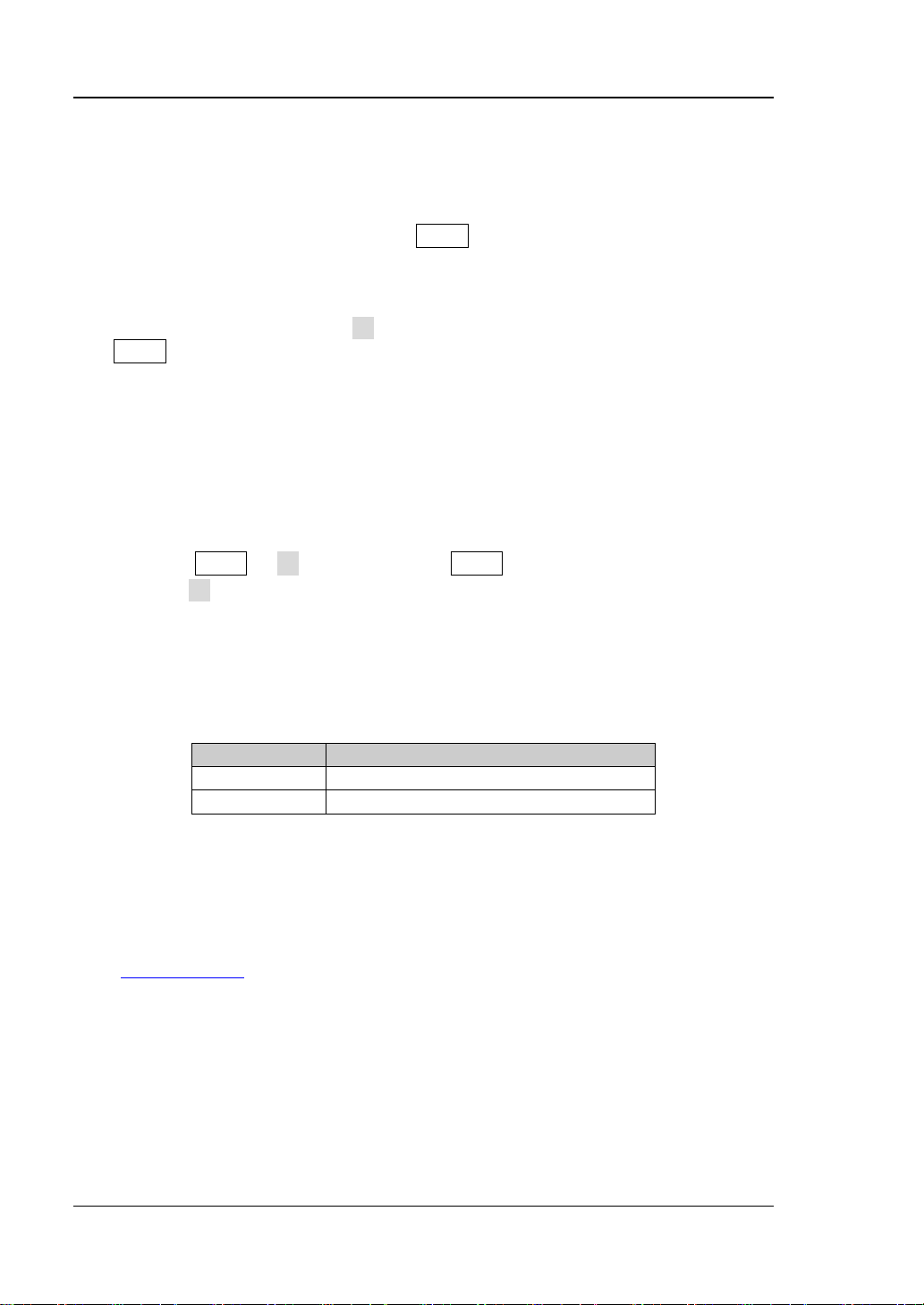
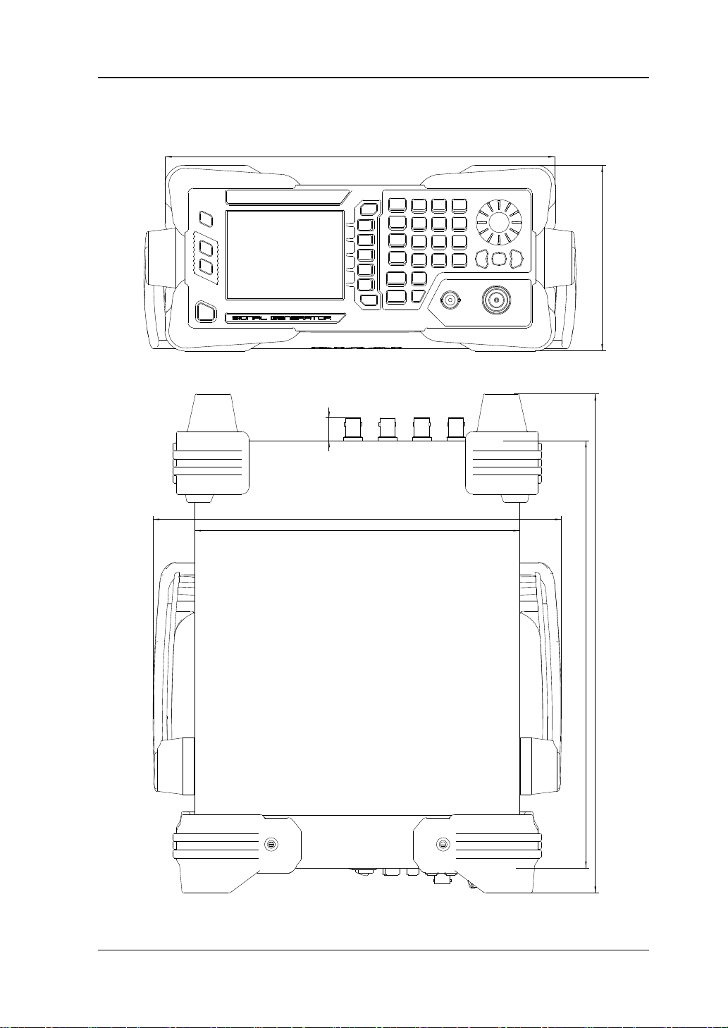
236
112
261.5
208
3
18.
40
27
2.4
0
14.70
Appearance and Dimensions
Figure 1-1 Front View (unit: mm)
Figure 1-2 Top View (unit: mm)
DSG800 User's Guide 1-3
Page 20
RIGOL Chapter 1 Quick Start
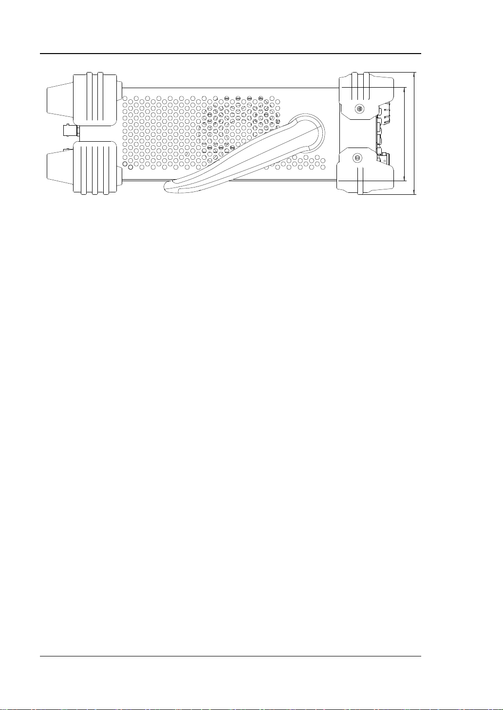
85
.5
1
11
2
Figure 1-3 Side View (unit: mm)
1-4 DSG800 User's Guide
Page 21
Chapter 1 Quick Start RIGOL
Restore the instrument to the preset state (the factory
3.5 inch TFT hig h-resolution (320×240) color LCD. The
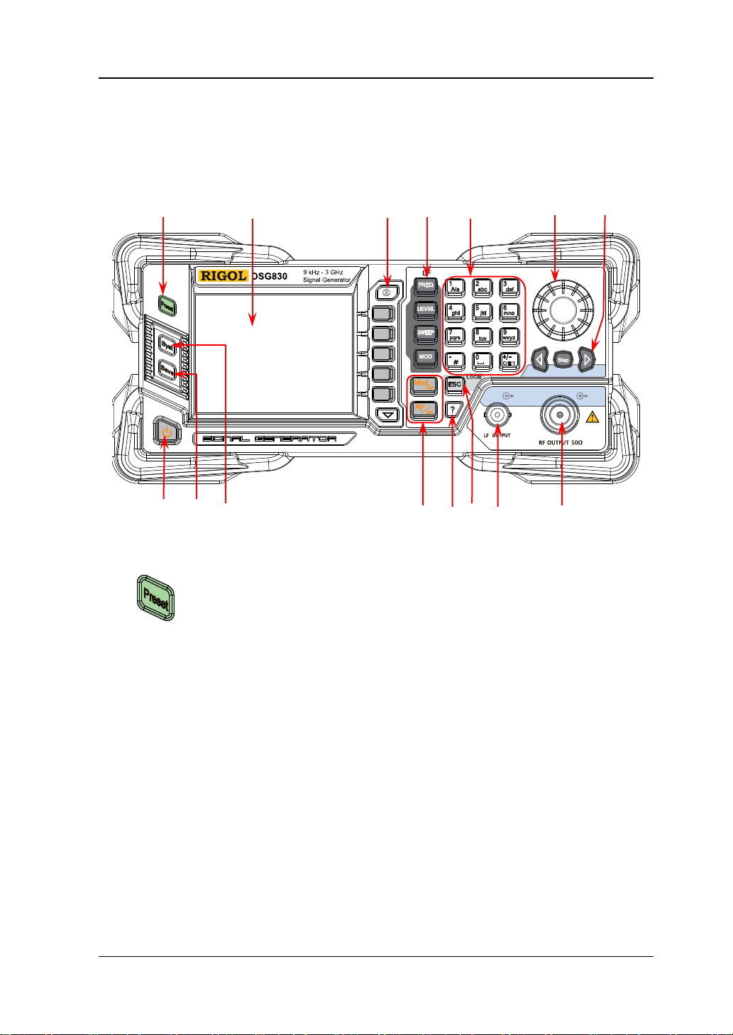
Front Panel Overview
The front panel of DSG800 series RF signal generator is as shown in the figure below.
You can click the number in the figure to view the corresponding introduction.
1 2 3 4 5 6 7
1. Restore to Preset Key
8 9 10 11 12 13 14 15
Figure 1-4 Front Panel
default state or user-stored state). For the detailed
information, refer to "
2. LCD
current settings and state of the instrument can be clearly
displayed. For the detailed information, refer to "
Interface".
DSG800 User's Guide 1-5
Reset".
User
Page 22
RIGOL Chapter 1 Quick Start
Display switching key. In the menu page of any function,
can use the knob or direction keys to switch the parameter
selected. In addition, y ou can press any f uncti on key to e xit
Menu softkeys correspon ding to the menus display ed at the
Menu page up/do w n key.
Set the frequency parameters of the RF output signal as
Set the amplitude parameters of the RF output signal and
Set the sweep type, sweep manner, sweep mode and etc.
Set the related parameters of amplitude modulation (AM),
3. Menu Control Keys
4. Function Keys
you can pr ess th is key to open the parameter information
display interface of the current function. At this point, you
tabs to view the parameter information of different
functions. Pressin g this key a gain will swit ch to the f unction
menu corresponding to the parameter tab currently
the parameter information display interface.
left of the softkeys respectively. Pressing the softkey will
activate the corresponding menu.
well as the related parameters of LF output. For the
detailed information, refer to "
To Set the Frequency/LF
Parameters".
provide the flatness calibration function. For the detailed
information, refer to "
Parameters
".
To Set the Amplitude
For the detailed information, refer to "Sweep".
frequency modulation (FM), phase modulation (ØM), pulse
modulation and pulse generator. For the detailed
information, refer to "
Modulation".
1-6 DSG800 User's Guide
Page 23
Chapter 1 Quick Start RIGOL
The numeric keyboard supports Chinese characters, English uppercase
The multiplexing keys of the numbers and letters are used to directly input the
Used to switch among Chinese, English and number input
In number input mode, press this key to input 1.
The multiplexing key of 0 and space.
In number input mode, press this key to insert a decimal
In Chinese input mode, this key is invalid.
When setting a parameter, the knob is used to modify the
switch the parameter tabs.
5. Numeric Keyboard
/lowercase characters, numbers and commonly used symbols (include the
decimal point, #, space and positive/negative s ign +/-). It is mainly used to edit
the f il e or folder name and set the parameters.
desired numbers or letters.
modes.
When setting a parameter, the input mode is f ixed at
number and this ke y is used to in put the sign ("+" or "-") of
the value.
In English input mode, press this key to switch between
uppercase and lowercase letter inputs.
In number input mode, press this key to input 0.
In Chinese or English input mode, press this key to input a
space.
point at the current cursor position.
In English input mode, press this key to input "#".
6. Knob
value at the cursor or modify the parameter value at the
current step.
When editing a filename, it is used to select the desired
character.
For the storage function, it is used to select the current
directory or file.
In the parameter inf ormation display inte rface, it is used t o
DSG800 User's Guide 1-7
Page 24
RIGOL Chapter 1 Quick Start
When setting a parameter, Step is used to set the step of
direction keys ar e u sed to switch the parameter tabs.
It is use d to turn on or off t he RF signal generator. You can
due to misoperation.
Store and recall various types of files (such as the
Set the system-related parameters. For the detailed
7. Direction Keys/Step Key
the parameter currently selected; the direction keys are
used to enter the parameter editing state and move the
cursor to the specified digit.
For the storage function, the direction keys are used to
collapse and expand the directory currently selected.
When editing a filename, the direction keys are used to
select the desired character.
In the parameter information display interface, the
8. Power Key
use the following method to enable or disable this key.
Press Syst Pwr Status to select "Default" or "Open".
When "Default" is selected, you need to press this key to
start the instrument after the instrument is powered on.
When "Open" is selected, the instrument will start
automatically after it is powered on.
Besides, this key provides the delayed switching function
(namely, the instrument can be turned on or off only
when you press this key and hold it down for a certain
period of time) to avoid the shut-down of the instrument
9. Store and Recall Key
instrument state). For the detailed information, refer to
"
Store and Recall".
10. System Setting Key
information, refer to "To Set the System Parameters".
1-8 DSG800 User's Guide
Page 25
Chapter 1 Quick Start RIGOL
Used to turn on or off the RF output.
Used to turn on or off the RF modulation output.
turned off.
To get the help information of any front panel key or
key.
When setting a parameter, this key is used to clear the
exit the current menu and return to the previous menu.
11. Output Control Keys
— Press this key; the backlight of the key and the RF
label in the function status area in the user interface
are illuminated. At this point, the RF output is turned
on and the [RF OUTPUT 50Ω] connector outputs
RF signal according to the current configuration.
— Press this key again; the backlight of the key turns of f
and the RF label in the function status area in the
user interface is grayed out. At this point, the RF
output is turned off.
— When a modulation function (AM, FM, ØM or Pulse
Mod) is turned on, press this key; the backlight of t he
key and the MOD label in the function status area in
the user interface are illuminated. At this point, the
RF modulation output is turned on and the [RF
OUTPUT 50Ω] connector outputs the mo dulated R F
signal according to the current configuration (the
backlight of RF/on must be illuminated).
— Press this key again and the backlight of the key
turns off. At this point, the RF modulation output is
12. Built-in Help System
menu softkey, press this key and then press the desired
13. Exit Key
number in the editing window and exit the parameter
input state.
When editing a filename, this key is used to clear the
characters in the input bar.
In the keyboard test state, this key is used to exit the
current test state.
When the instrument is working in the remote mode, you
can press this key to return to the local mode.
After you select the next level of menu, this ke y is us ed to
DSG800 User's Guide 1-9
Page 26
RIGOL Chapter 1 Quick Start
When the LF output is turned on, this connector is used to
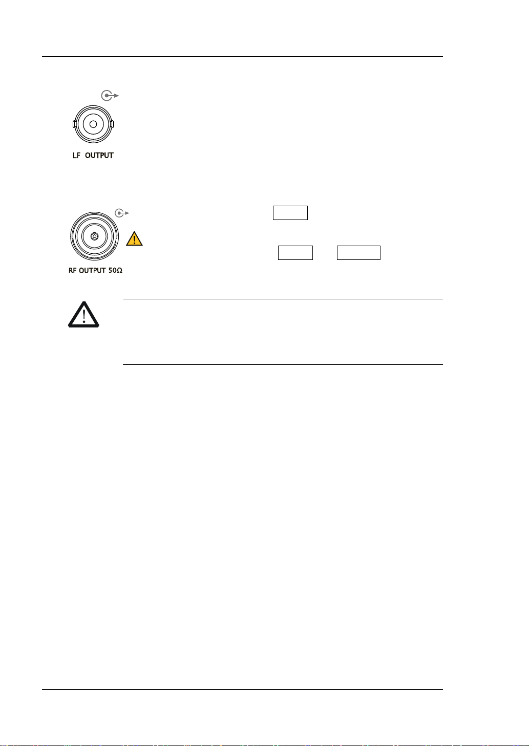
When the backlight of RF/on is illuminated, this
modulated signal.
CAUTION
To avoid dama ging the inst rument, the reverse DC v oltage on t he
segment.
14. LF Output Conne ctor
output the LF signal.
15. RF Output Connector
connector is used to output the RF signal and RF sweep
signal.
When the backlights of RF/on and Mod/on are both
illuminated, this connector is used to output the RF
RF output connector cannot exceed 50 V and the reverse power
cannot e xceed +30 dBm (1W) in the 1 MHz to 3 GHz frequenc y
1-10 DSG800 User's Guide
Page 27
Chapter 1 Quick Start RIGOL
The function of this connector is determined by the
When the pulse modulation source is "Int" and the pulse
set to "Single" or "Train".
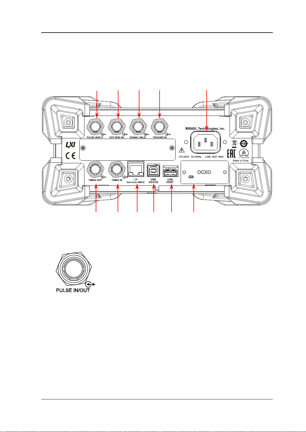
Rear Panel Overview
The rear panel of DSG800 series RF signal generato r is as sh own in the figure below .
You can click the number in the figure to view the corresponding introduction.
1 2 3 4 5
6 7 8 9 10 11
Figure 1-5 Rear Panel
1. Pulse Signal Input/Output Connector
current working mode of pulse modulation.
PULSE IN:
When the pulse modulation source is "Ext", this
connector is used to input the external pulse signal.
PULSE OUT:
output is turned on, this connector is used to output the
pulse signal generated by the internal generator. This
output signal is related to the pulse "Mode" and can be
DSG800 User's Guide 1-11
Page 28
RIGOL Chapter 1 Quick Start
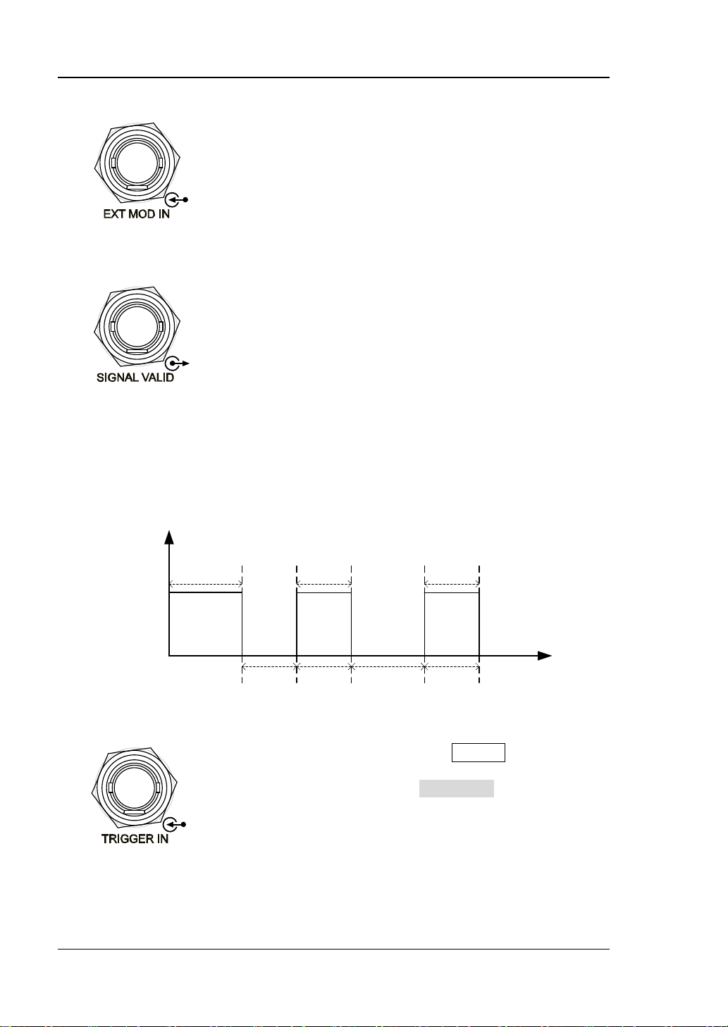
When the modulation source of AM or FM/ØM is
When the RF output frequency or amplitude is
stable (namely, the signal is valid).
3.3V
0V
Power-on Time
RF Valid
Configuration
Time
Configuration
Time
RF Valid
… …
V
T
When the trigger mode of SWEEP is “Ext”, this
exter nal gated s ignal.
2. External Modulation Input Connector
set to "Ext", this connector is used to input the
external modulating signal.
3. Signal Valid Output Connector
modified, after a certain response and processing
time of the internal circuit of the instrument, the
instrument outputs RF signal with the specified
frequency and amplitude via the RF output
connector at the front panel. During this process,
the [SIGNAL VALID] connector outputs a pulse
sync signal, indicating that the RF output signal is
valid.
— High Level (+3.3 V): indicate that the RF
signal is in configuration.
— Low Level (0 V): indicate that the RF signal is
4. External Trigger Input Connector
connector is used to input the external trigger
signal. You can press Trig Slope to set the
polarity of the trigger signal to "Pos" or "Neg".
When the pulse modulatio n source is "Int" an d the
trigger mode is "Ext Trig", it is used to input the
exter nal trigg er signal.
When the pulse modulatio n source is "Int" an d the
trigger mode is "Ext Gate", it is used to input the
1-12 DSG800 User's Guide
Page 29
Chapter 1 Quick Start RIGOL
Power input connector.
It is used to output the internal 10 MHz reference
It is used to input the external 10 MHz reference
data sheet of this product.
The instrument complies with LXI Core 2011
The instrument complies with USBTMC class
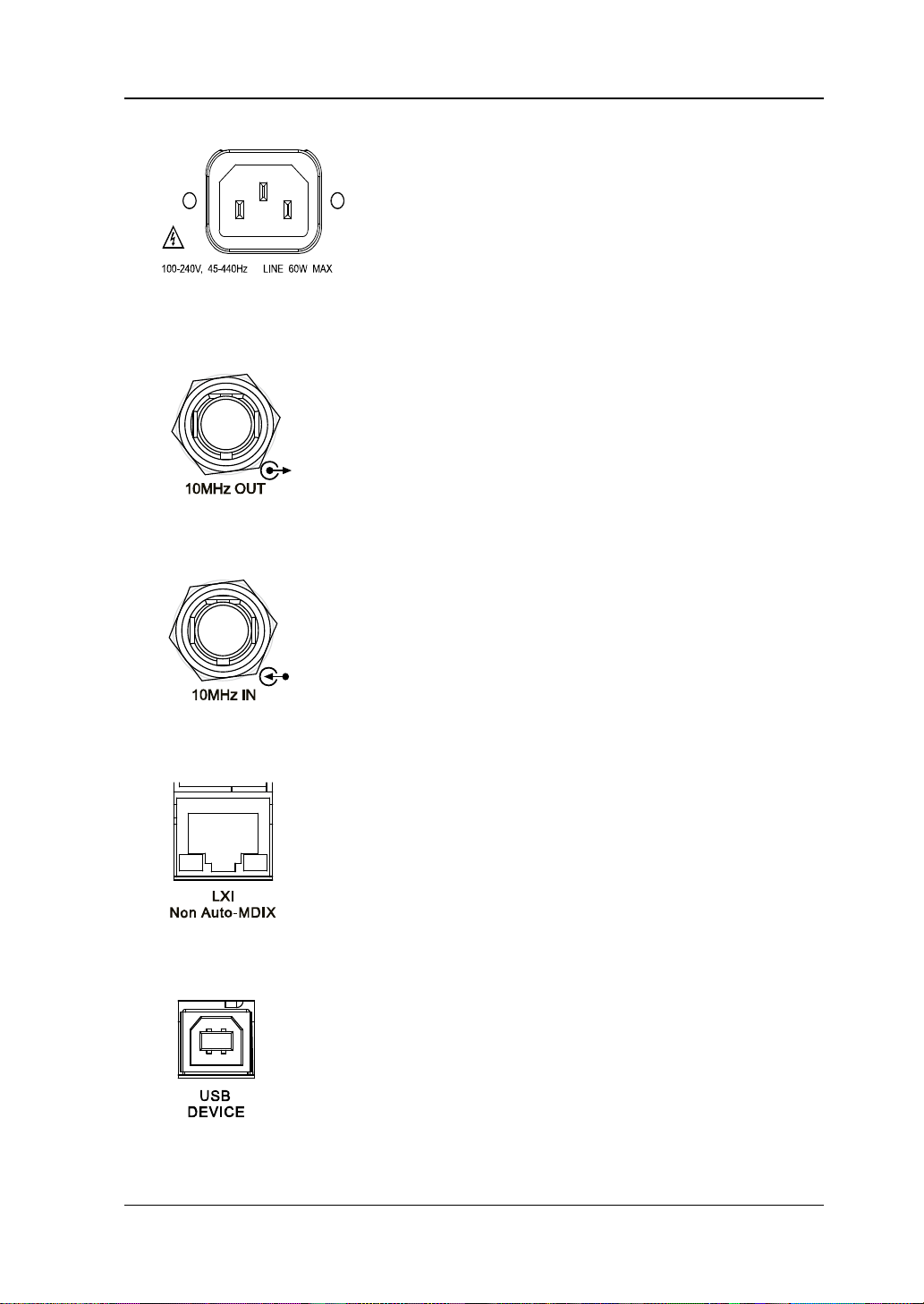
5. Power Input Connector
This RF signal generator can accept 100 V to 240
V, 45 Hz to 440 Hz AC power supplies. The power
consumption of the instrument cannot exceed 60
W.
6. Reference Signal Output Connector
clock signal which is used to synch r onize the
generator with other instruments. For more
information about the specifications of the clock
signal output from this connector, refer to the data
sheet of this product.
7. Reference Signal Input Connector
8. LAN
9. USB DEVICE
clock signal which is used to synchronize the
generator with other instruments. For more
information about the s pecifications of the external
clock signal input from this connector, refer to the
Device standard. It supp orts WebServer, Socket
and other remote control modes.
This interface is used to connect the RF signal
generator to the PC or network f or remote control.
protocol.
This interface is used to connect the PC for remote
control.
DSG800 User's Guide 1-13
Page 30
RIGOL Chapter 1 Quick Start
This interface is used to connect the USB storage
OCXO is an oven controlle d crystal oscillator. It is
please refer to the data sheet of this product.
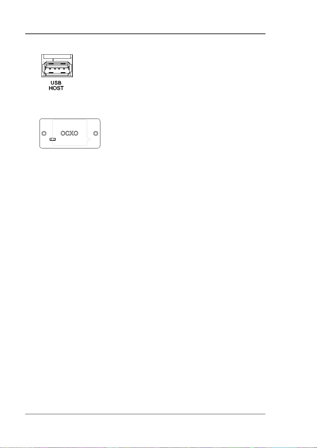
10. USB HOST
device to update the system or store the system
states and etc.
11. OCXO (Option OCXO-B08)
a frequency reference source with higher
temperature stability.
Note: Sixty minutes of warm-up is required for
the OCXO to reach its rated frequency.
For the ordering information of this option,
1-14 DSG800 User's Guide
Page 31

Chapter 1 Quick Start RIGOL
CAUTION
To Use DSG800 for the First Time
To Connect the Power Supply
Please connect the RF signal generator to AC power supply using the power cable
supplied in the accessories. This RF signal generator can accept 100 V to 240 V, 45
HZ to 440 Hz AC power supplies. The pow er consumption of the instrument cannot
exceed 60 W. When the RF signal generator is conne cted to A C power s upply via thi s
connector, the instrument selects the correct voltage range automatically and users
do not need to select the voltage range manually.
To avoid electric sho ck, use the standard power cable.
Power-on Inspection
After the power supply is correctly connected, press the power key
panel to t urn on the RF signal generator. During the start-up, the instrument
performs initialization and self-test. After that, the instrument enters the default
interface.
at the front
To Set the System Language
DSG800 series RF signal generator supports multiple system languages. You can
press Syst Language to switch the system language.
DSG800 User's Guide 1-15
Page 32

RIGOL Chapter 1 Quick Start
User Interface
In this manual, DSG830 is taken as an example to illustrate the user interface of
DSG800 series RF signal generator, as shown in the figure below.
1 2 3 4
5 6
Figure 1-6 User Interface
1. Frequency Area
Display the current frequency settings of the RF signal generator.
—
: continuous sweep label. It is displayed when the sweep manner is
"Freq" or "Freq & Lev" and the sweep mode is "Cont".
—
: single sweep label. It is displayed when the sweep manner is "Freq"
or "Freq & Lev" and the sweep mode is "Single".
—
: forward sweep label. It is displayed when the sweep manner is "Freq"
or "Freq & Lev" and the sweep direction is "Fwd".
—
: downward sweep label. It is displayed when the sweep manner is
"Freq" or "Freq & Lev" and the sweep direction is "Down".
—
: frequency sweep progress bar. It is displayed when the
sweep manner is "Freq" or "Freq & Lev".
2. Amplitude Area
Display the current level settings of the RF signal generator.
—
—
: displayed when the flatness calibration is turned "On".
: continuous sweep label. It is displayed when the sweep manner is
"Level" or "Freq & Lev" and the sweep mode is "Cont".
—
: single sweep label. It is displayed when the sweep manner is "Level"
or "Freq & Lev" and the sweep mode is "Single".
1-16 DSG800 User's Guide
Page 33

Chapter 1 Quick Start RIGOL
Icon
Explanation
Icon
Explanation
The RF output is not turned
selected.
The LF output is not
waveform is selected.
The RF output is not turned
manner is selected.
The LF output is not
waveform is selected.
The RF output is turned on
selected.
The LF output is turned
selected.
The RF output is turned on
manner is selected.
The LF output is turned
is selected.
— : forward sweep label. It is displayed when the sweep manner is
"Level" or "Freq & Lev" and the sweep direction is "Fwd".
—
: downward sweep label. It is displayed when the sweep manner is
"Level" or "Freq & Lev" and the sweep direction is "Down".
—
: amplitude sweep progress bar. It is displayed when the
sweep manner is "Level" or "Freq & Lev".
3. Status Bar
Indicate the current system states of the RF signal generator.
—
—
—
—
: the RF signal generator is working in the remote control mode.
: the RF signal generator is working in the local operation mode.
: displayed when a USB storage device is detected.
: displayed when the instrument parameter information interface is
opened.
4. Menu Display Area
The menu items displayed i n this a rea correspond to the softkeys at the right of
the screen respectively. Pressing any softkey can enable the corresponding
menu function.
5. Message Display Area
Display the operation error messages and prompt messages. You can press
Syst Information System Msg to view the messages. When multiple
messages are generated, you can use the direction keys or knob to select the
desired message.
6. Function Status Area
Display the current states of the functio ns of the RF signal gene rator. The status
icons that might be displayed in the function status area are as shown in the
table below.
DSG800 User's Guide 1-17
on and no sweep manne r is
on and only a single sweep
and no sweep manner is
and only a single sweep
turned on and Sine
turned on and Square
on and Sine waveform is
on and Square waveform
Page 34

RIGOL Chapter 1 Quick Start
The RF modulation output
AM is turned on.
The RF modulation
AM is turned on.
The RF modulation output
FM is turned on.
The RF modulation
FM is turned on.
The RF modulation output
ØM is turned on.
The RF modulation
ØM is turned on.
The RF modulation output
Pulse is turned on.
The RF modulation
Pulse is turned on.
The RF modulation output
FM are turned on.
The RF modulation
and FM are turned on.
The RF modulation output
ØM are turned on.
The RF modulation
and ØM are turned on.
The RF modulation output
Pulse are turned on.
The RF modulation
and Pulse are turned on.
The RF modulation output
Pulse are turned on.
The RF modulation
and Pulse are turned on.
The RF modulation output
Pulse are turned on.
The RF modulation
and Pulse are turned on.
The RF modulation
on.
The RF modulation
on.
The RF modulation output
is turned on.
is not turned on and only
is not turned on and only
is not turned on and only
is not turned on and only
is not turned on; AM and
is not turned on; AM and
is not turned on; AM and
is not turned on; FM and
output is turned on and
output is turned on and
output is turned on and
output is turned on and
output is turned on; AM
output is turned on; AM
output is turned on; AM
output is turned on; FM
is not turned on; ØM and
The RF modulation output
is not turned on; AM, FM
and Pulse are turned on.
The RF modulation output
is not turned on; AM, ØM
and Pulse are turned on.
is not turned on and none
of the modulation functions
Tip: Press MOD and the AM/FM/ØM/PUL modulation icons are displayed in the
function status area. If a modulation function is turned on (or off), the
corresponding icon will be illuminated (or grayed out).
1-18 DSG800 User's Guide
output is turned on; ØM
output is turned on; AM,
FM and Pulse are turned
output is turned on; AM,
ØM and Pulse are turned
-- --
Page 35

Chapter 1 Quick Start RIGOL
To Use the Built-in Help System
The DSG800 built-in help syste m p rovides the help information of all the function
keys and menu softkeys at the front panel. Users can view the help information of
any key when operating the instrument.
1. Acquire the built-in help information
Press ? and press the desired function key or menu softkey; the help
information of the key will be displayed in the instrument interface.
2. Page up/down
When the help information is displayed in multiple pages, you can use the
direction keys or knob to switch the help information page.
3. Turn off the current help information
When help information is displayed in the instrument inte rface, pressin g any ke y
(except the direction keys and knob) at the front panel will turn off the help
information currently display ed.
4. Acquire the help information of a menu softkey
Press ? and the prompt message about how to acquire the help information
is displayed in the instrument interface. Then, press the desired menu softkey
and the help information of the menu item cor responding to this men u softkey is
displayed in the instrument interface.
5. Acquire the help information of any function key
Press ? and the prompt message about how to acquire the help information
is displayed in the instrument interface. Then, press the desired function key
and the help inf ormation of the fun ction of t he key is displaye d in the inst rument
interface.
DSG800 User's Guide 1-19
Page 36

Page 37

Chapter 2 Front Panel Operations RIGOL
Chapter 2 Front Panel Operations
This chapter introduces each function key at the front panel as well as the menu
functions under it in details.
The topics of this chapter:
To Set the Frequency/LF Parameters
To Set the Amplitude Parameters
Sweep
Modulation
Store and Recall
To Set the System Parameters
DSG800 User's Guide 2-1
Page 38

RIGOL Chapter 2 Front Panel Operations
To Set the Frequency/LF Parameters
Frequency
Set the RF output frequency.
Press FREQ, use the numeric keyboard to input the frequency value and select the
desired unit from the pop-up unit menu.
The frequency units available are GHz, MHz, kHz and Hz.
You can press Backspace to delete the number at the left of the cursor.
You can press the left/right direction key to enter the parameter editing state
and move the curso r to t he s pecified digit; then, rotate the knob to modify the
value.
After the frequency is set, you can rotate the knob to modify the frequency at
the current step.
You can press FREQ and then press Step to set the step.
LF Output
LF output denotes the output of the low-frequency signal generated by the internal
generator of the RF signal generator. The LF output can be one of the two commonly
used waveforms (sine or squar e). You can set the frequency and ampl itude of the
low-frequency signal.
Press FREQ LF to enter the LF output parameter setting menu.
To Turn on the LF Output
Press FREQ LF Switch to turn "On" or "Off" the LF output. When "On" is
selected, the LF label and the label of the waveform currently selected (Sine or
Square) in the function status area of the user interface are illuminated. At this point ,
the [LF OUTPUT] connector (as shown in the figure below) outputs the LF signal
according to the current configuration.
2-2 DSG800 User's Guide
Page 39

Chapter 2 Front Panel Operations RIGOL
Explanation
The settable range of square frequency is from 0 Hz to 20 k Hz.
To Select the LF Waveform
Press FREQ LF Waveform to set the waveform of the LF output signal to
"Sine" or "Square". The default is "Sine".
To Set the LF Amplitude
Press FREQ LF Level to set the amplitude of the LF signal.
Use the numeric keyboard to input the amplitude value and select the desired
unit from the pop-up unit menu.
The amplitude units available are V, mV, uV, nV and dBm.
You can press Backspace to delete the number at the left of the cursor.
You can press the left/right direction key to enter the parameter editing state
and move the cursor to the specified digit; then, rotate the knob to modi fy the
value.
You can also rotate the knob to modify the amplitude at the current step.
You can press Step to set the step.
The settable ranges of the amplitudes of sine an d sq uare a re b oth from 0 V to 3
V. Note that when the frequency is 0 Hz, the LF output is DC signal and the
settable range of the amplitude is from -3 V to 3 V.
To Set the LF Frequency
Press FREQ LF Freq to set the frequency of the LF signal.
Use the numeric keyboard to input the frequency value and select the desired
unit from the pop-up unit menu.
The frequency units available are GHz, MHz, kHz and Hz.
You can press Backspace to delete the number at the left of the cursor.
You can press the left/right direction key to enter the parameter editing state
and move the cursor to the specif ied digit; the n, ro tat e the knob to modify the
value.
After the frequency is set, you can rotate the knob to modify the frequency at
the current step.
You can press Step to set the step.
The settable range of sine frequency is from 0 Hz to 200 kHz.
DSG800 User's Guide 2-3
Page 40

RIGOL Chapter 2 Front Panel Operations
To Set the Amplitude Parameters
Amplitude
Set the RF output amplitude.
Press LEVEL, use the numeric keyboard to input the amplitude value and se lect the
desired unit from the pop-up unit menu.
The amplitude units available are dBm, -dBm, mV, uV and nV.
You can press Backspace to delete the number at the left of the cursor.
You can press the left/right direction key to enter the parameter editing state
and move the cursor to the specified digit; then, rotate the knob to modi fy the
value.
You can also rotate the knob to modify the amplitude at the current step.
You can press LEVEL and then press Step to set the step.
Flatness Calibration
The flatness calibration function can adjust the RF output amplitudes corresp onding
to the frequency points within the frequenc y r ange o f the inst rument t o compe nsate
for the external loss caused by the cables, switches or other devices. You can load
the flatness calibration lists st ored in the i nternal or external me mory to DSG8 00 and
view the list contents.
1. Set the flatness calibration status
Press LEVEL Flatness Switch to turn "On" or "Off" the flatness
calibration function. When the flatness calibration function is turned on, the UF
status label is displayed in the amplitude area of the user interface.
2. Flatness calibration list
Press LEVEL Flatness Cal List to enter the flatness calib ration list me n u.
Load a li s t
Press Load to open the store and recall interface. At this point, you can
select and read the flatness calibration list files stored. For the detailed
operations, refer to "
directory of the file loaded is displayed in View.
The format of the calibration list file loaded is as shown in the table on the
next page.
Store and Recall". After a list is loaded, the storage
2-4 DSG800 User's Guide
Page 41

Chapter 2 Front Panel Operations RIGOL
SN
Freq
Level
[1]
1
207.854 000 00 MHz
-70.50 dB
2
304.000 000 00 MHz
7.45 dB
3
800.000 000 00 MHz
-17.80 dB
[1]
Note
frequency point, only the actual output amplitude wil l be affected and the amplitude
display value will not change.
: Amplitude calibration value. When calibrating the amplitude of the current
View the list
You can press View to view the information of the flatness calibration list
currently loaded. Pressing any key (except the direction keys and knob) at
the front panel will return to the flatness calibration list menu.
Note: This menu is only valid after a list file is loaded.
Amplitude Uni t
Set the unit of the RF output amplitude.
Press LEVEL Level Unit and select the desired unit from the pop-up unit menu.
The output amplitude unit s available are dBm, dBmV, dBuV , Volt s and W atts. W herein,
dBm, dBmV and dBuV are logarithmic units; Volts and Watts are linear units. The
default is dBm.
DSG800 User's Guide 2-5
Page 42

RIGOL Chapter 2 Front Panel Operations
Sweep
When the sweep function is turned on, the RF signal generator outputs RF sweep
signal from the [RF OUTPUT 50Ω] connector (as shown in the figure below) a t the
front panel (at this point, the RF output should be turned on).
Sweep Manner
DSG800 provides three sweep manners ("Freq", "Level" and "Freq & Lev"). The
sweep function is turned on when any of the sweep manners is selected and the
Sweep label in the functio n status area of the user interface is illuminate d. By default,
the sweep function is turned off.
Press SWEEP Sweep to select the desired sweep manner.
Off: the default state. Turn off the sweep function.
Freq: turn on the frequency sweep function. At this point, the frequency sweep
progress bar is displayed in the frequency area in the user interface.
Level: turn on the a mplitude swee p function. At this point , the a mplitude swe e p
progress bar is displayed in the amplitude area in the user interface.
Freq & Lev: turn on the frequency and amplitude sweep functions at the same
time. At this point, the frequency and amplitude sweep progress bars are
displayed in the frequency and amplitude areas in the user interface
respectively.
Sweep Direction
Press SWEEP and use the menu page up/dow n key
the menu; then, press Direct to select "Fwd" or "Down" and the default is "Fwd".
Fwd: the RF signal generator sweeps from the start frequency or start level to
the stop frequency or stop level. The progress bars in the frequency area and
amplitude area in the user interface sweep from left to right.
Down: the RF signal generator sweeps from the stop frequency or stop level to
the start frequency or start level. The progress bars in the frequency area and
amplitude area in the user interface sweep from right to left.
to open the 3/3 page of
2-6 DSG800 User's Guide
Page 43

Chapter 2 Front Panel Operations RIGOL
SN
Freq
Level
[1]
Time
[2]
1
2.000 000 000 10 GHz
-10.00 dBm
500.00 ms
2
1.994 152 687 00 GHz
-50.00 dBm
500.00 ms
3
1.888 000 000 00 GHz
-60.85 dBm
500.00 ms
Sweep Type
DSG800 provides two sweep types ("List" and "Step") and the default is "Step".
List Sweep
1. Select the list sweep mode
Press SWEEP Type to select "List". At this point, the RF signal generator
sweeps according to the sweep list currently loaded.
2. Sweep list
Press SWEEP and use the page up/ down key
menu; then, press Lis t Swp to enter the sweep list menu.
Load a li s t
Press Load to open the store and recall interface. At this point, you can
select and read the sweep list files stored. For the deta iled operations, refer
Store and Recall". After a list is loaded, the storage directory of the
to "
file loaded is displayed in View.
The format of the sweep list file loaded is as shown in the table below.
to open the 2/3 pa ge of t he
[1]
Note
Note
: The amplitude corresponding to the frequency point set.
[2]
: The duration of a sweep step.
View the list
You can press View to v iew the information of the sweep list currently
loaded. Pressing any key (exce pt the dire ction keys and knob) at the front
panel will return to the sweep list menu.
Note: This menu is only valid after a list file is loaded.
Step Sweep
1. Select the step sweep mode
Press SWEEP Type to select "Step". At this point, the RF signal generator
performs step sweep according to the current settings.
2. Set the sweep parameters
Press SWEEP and use the menu page up/down key
of the menu; then, press Step Swp to set the sweep parameters, such as the
DSG800 User's Guide 2-7
to open the 2/3 page
Page 44

RIGOL Chapter 2 Front Panel Operations
Explanation
Explanation
The start level and stop lev el are the a mplitude upper an d lower limits of
Lev".
start frequency, stop frequency, start level, stop level and number of sweep
points.
Start Frequency
Press Start Freq, use the numeric keyboard to i nput the start frequency
value and select the desi red unit f rom the po p-up unit menu. You can press
Backspace to delete the number at the left of the cursor.
Stop Frequency
Press Stop Freq, use the numeric keyboard to input the stop frequency
value and select the desi red unit f rom the po p-up unit menu. You can press
Backspace to delete the number at the left of the cursor.
The start frequency and stop frequency are the frequency upper and
lower limits of frequency sweep respectively.
When the sweep direction is forward, the RF signal generator
sweeps from the start frequency to the stop frequency.
When the sweep direction is downward, the RF signal generator
sweeps from th e stop frequency to the start frequency.
When the "Start Freq" or "Stop Freq" is modified, the RF signal
generator will restart the sweep and output from the specified "Start
Freq" or "S t o p Freq".
Start Level
Press Start Lev, use the numeric keyboard to input the start level value
and select the desired unit from the pop-up unit menu. You can press
Backspace to delete the number at the left of the cursor.
Stop Level
Press Stop Lev, use the numeric k eyboard to input the sto p level v alue and
select the desired unit from the pop-up unit menu. You can press
Backspace to delete the number at the left of the cursor.
amplitude sweep respectively.
When the sweep direction is forward, the RF signal generator
sweeps from the start level to the stop level.
When the sweep direction is downward, the RF signal generator
sweeps from the stop level to the start level.
When the "Start Lev" or "Stop Lev" is modified, the RF signal generator
will restart the sweep and output from the spe cified "Start Lev" or "Stop
2-8 DSG800 User's Guide
Page 45

Chapter 2 Front Panel Operations RIGOL
F/L
T
Start Frequency
/Start Level
Start Frequency
/Start Level
Ramp
Triangle
Stop Frequency
/
Stop Level
Stop Frequency
/Stop Level
Number of Sweep Points
Press Points, use the numeric keyboard to input the number of sweep
points and then press Enter. You can press Backspace to delete the
number at the left of the cursor.
Dwell Time
The dwell time denotes the duration of a sweep step.
Press Dwell Time, use the numeric keyboard to input the time value and
select the desired unit from the pop-up unit menu. You can press
Backspace to delete the number at the left of the cursor.
Swe e p Space
The sweep space denotes the mode in which the instrument changes from
one frequency or amplitude to another within one step.
Press Swp Space to select "Log" or "Lin" sweep space. No te that level
sweep only supports "Lin" sweep space.
Swe e p Shape
The sweep shape denotes the cycle mode of multiple sweeps.
Press Shape to select "Ramp" or "Triangle" sweep shape. When the sweep
direction is "Fwd", the "Ramp" and "Triangle" sweep shapes are as shown in
the fi g ure below.
Ramp: the sweep period always starts from the start frequency or start level
to the stop frequency or stop level and the sweep sequence is similar to a
DSG800 User's Guide 2-9
Page 46

RIGOL Chapter 2 Front Panel Operations
ramp waveform .
Triangle: the sweep period always starts from the start frequency or start
level to the stop frequency or stop level and then returns back to the start
frequency or start level. The sweep sequence is similar to a triangle
waveform.
Sweep Mode
Press SWEEP Mode to select "Cont" or "Single" sweep and t he default is "Cont".
Cont: when continuous sweep is selected, the continuous sweep label is
displayed in the frequency or amplitude area in the user interface. When the
trigger condition is met, the instrument sweeps continuously according to the
current setting.
Single: when single sweep is selected, the single sweep la bel is displayed in the
frequency or amplitude are a in t he use r int erf ace. When the trigger condition is
met, the instrument performs a single sweep according to the current setting
and then stops.
Single Sweep
If the current sweep mode is "Cont", press Single to switch the sweep mode to
"Single" and the instrument will perform a single sweep if the trigger condition is
met.
If the current sweep mode is "Single", press Single and the instrument will perform
a single sweep if the trigger condition is met.
To Reset the Sweep
If the current sweep direction is "Fwd", press Reset Swp, the instrument stops the
current sweep and restarts the sweep from the start frequency or start level.
If the current sweep di rection is "Down", press Reset Swp, the instrument stops the
current sweep and restarts the sweep from the stop frequency or stop level.
2-10 DSG800 User's Guide
Page 47

Chapter 2 Front Panel Operations RIGOL
Trigger Mode
1. Trigger Mode
Select the trigger mode of the whole sweep period.
Press SWEEP and use the menu page up/ dow n k ey
of the menu; then, press Trig Mode to select "Auto", "Key", "Bus" or "Ext"
trigger.
Note: The following descriptions are valid when the trigger mode of each sweep
point in the sweep period is met.
Auto Trigger
The default mode is auto. If the sweep mode is set to "Cont", the
instrument will start sweeping once a sweep manner is selected. If the
sweep mode is set to "Single", you need to press Single to meet the single
sweep condition; after that, the instrument will start a sweep and then
stops.
Key Tr igger
When "Key" trigger is selected, if the sweep mode is set to "Cont", th e
instrument starts a sweep each time Key Trig is pressed; if the sweep
mode is set to "Single", you need to press Single to meet the single sweep
condition and after that, the instrument starts a sweep and then stops each
time Key Trig is pressed.
Bus Trigger
When "Bus" trigger is selected, if the sweep mode is set to "Cont", the
instrument starts a sweep each time the "*TRG" command is sent; if the
sweep mode is set to "Single", you need to press Single to meet the single
sweep condition and a fter that, the instrument starts a sweep and then
stops each time the "*TRG" command is sent.
External Trigger
In external trigger, the RF signal generator receives the trigger signal input
from th e [TRIGGER IN] connector (a s s hown in the fig ure on the next
page) at the rear panel. If the sweep mode is set to "Cont", the instrument
starts a sweep each t ime a TTL pulse signal with the specified polarity is
received. If the sweep mode is set to "Single", you need to press Single to
meet the single sweep condition; after that, the instrument starts a sweep
and then stops each time a TTL pulse signal with the specified polarity is
received.
to open the 2/3 page
DSG800 User's Guide 2-11
Page 48

RIGOL Chapter 2 Front Panel Operations
To specify the polarity of the TTL pulse signal, press Trig Slope to select
"Pos" or "Neg" and the default is "Pos".
2. Point Trigge r Mo d e
Select the trigger mode of each sweep point in a sweep period.
Press SWEEP and use the menu page up/down ke y
to open the 2/3 page
of the menu; then, press Point Trig to select "Auto", "Key", "Bus" or "Ext"
trigger.
Note: The following descriptions are valid when the trigger mode of the
corresponding sweep period is met.
Auto Trigger
The default mode is auto. If the sweep mode is set to "Cont", the
instrument will start sweeping each sweep point continuously within a
sweep period once a sweep manner is selected. If the sweep mode is set to
"Single", you need to press Single to meet the single sweep condition;
after that, the instrument starts to sweep and then stops after th e sweep
period expires.
Key Tr igger
When "Key" trigger is selected, if the sweep mode is set to "Cont", the
instrument starts to sweep a point each time Key Trig is pressed ; if the
sweep mode is set to "Single", you need to press Single to meet the single
sweep condition and after that, the instrument starts to sweep a point and
then stops after the sweep period expires each time Key Trig is pressed.
Bus Trigger
When "Bus" trigger is selected, if the sweep mode is set to "Cont", the
instrument starts to sweep a point each time the "*TRG" command is sent;
if the sweep mode is set to "Single", you need to press Single to meet the
single sweep condition and after that, the instrument starts to sweep a
point and then stops after the sweep period expires each time the "*TRG"
command is sent.
External Trigger
In externa l tri gge r m ode , the RF si gnal gene r ator re ceiv es t he tri gger s igna l
2-12 DSG800 User's Guide
Page 49

Chapter 2 Front Panel Operations RIGOL
Explanation
Point Trigger Mode. For example, when
input from the [TRIGGER IN] connector (as shown in the figure below) at
the rear panel. If the sweep mode is set to "Cont", the instrument starts to
sweep a point each time a TTL pulse signal with the specified polarity is
received. If the sweep mode is set to "Single", you need to press Single to
meet the single sweep condition; aft er that, the instrument starts to sweep
a point and then stops after the sweep period expires each time a TTL puls e
signal with the specified polarity is received.
To specify the polarity of the TTL pulse signal, press Trig Slope to select
"Pos" or "Neg" and the default is "Pos".
When executing the s weep o perat ion, the priorit y order of the conditions is
Single Sweep Trigger Mode
both the trigger mode and point trigger mode are set to "Key" trigger:
In "Cont" sweep mode, you need to press Key Trig to meet the
trigger mode of the whole period and then press Key Trig again to
meet the trigger mode of the points within the swee p period; then, the
instrument starts to sweep.
In "Single" sweep mode, you need to press Single to meet the single
sweep condition and then press Key Trig twice to meet the sweep
period trigger mode and point trigger mode respectively; then, the
instrument starts to sweep.
DSG800 User's Guide 2-13
Page 50

RIGOL Chapter 2 Front Panel Operations
Modulation
Amplitude Modulation (AM)
During amplitude modulation (A M), the mo dulating signal changes the amplitude of
the RF carrier waveform linearly.
Press MOD AM to enter the amplitude modulation parameter setting menu.
To Turn on Amplitude Modulation
Press Switch to select "On" or "Off".
On: turn on the AM fu nction. The AM la bel in the fun ction status a rea in the use r
interface is illuminated.
Off: turn off the AM function and this is the default state.
Note: If a sweep manner is selected and the step sweep time is lower than 30 ms,
"You can turn on the AM when sweep time is greater than 30ms" will be displayed in
the user interface when amplitude modulation is turned on.
To Select the Modulation Source
Press Source to s elect "Int" or "Ext" modulation source.
1. Internal So u r c e
When "Int" is selected , the internal modulation sour ce is turned on. At this point,
the instrument provides the modulating signal and you can set the modulation
frequency and modulation waveform of the modulating signal.
2. External Source
When "Ext" is selected, Freq and Waveform are grayed out and disabled. The
RF signal generator receives the external modulating signal input fr om the [EXT
MOD IN] connector (as shown in the figure below) at the rear panel. This
modulating signal can be any waveform.
Note: The input amplitude of the external modulating signal cannot exceed
+/-3 V (HighZ). To ensure the modulation performance, the input amplitude of
the external modulating signal should be less than 1 Vpp.
2-14 DSG800 User's Guide
Page 51

Chapter 2 Front Panel Operations RIGOL
a
m
sb
ΔP
asb
mΔP lg206 −=
To Set the Modulation Depth
The modulation depth denotes the extent of output amplitude variation and is
expressed as a percentage. The range of AM modulation de pth is fro m 0% to 1 00%.
Press Depth to set the AM modulation depth.
1. When "Int" modulation source is selected
The AM modulation depth (
) and the amplitude difference (
) between
the carrier and sidebands satisfy the following relation.
When the modulation depth is 0%, the instrument outputs a carrier signal
with a single frequency point.
The greater the modulation depth is, the smaller the difference between the
output amplitude and carrier amplitude will be.
2. When "Ext" modulation source is selected
100% modulation depth refers to the modulation depth corresponding to 1
Vpp input amplitude of the external modulation source.
When the input amplitude of the external modulation source is 0.5 Vpp, the
modulation depth actually measured is 50%.
To Select the Modulation Waveform
Press Source to select "Int" modulation source; press Waveform to select "Sine" or
"Square" and the default is "Sine".
Note: When "Ext" modulation source is selected, this menu is grayed out and
disabled.
To Set the Modulation Frequency
Press Source to s elect "Int" modulation source; press Freq to set the modulation
frequency.
Use the numeric keyboard or knob to input the desired frequency value.
For sine wa vefo rms, the r ange of the modulation freq uency is from 10 Hz to 100
kHz.
For square waveforms, the range of the modulation frequency is from 10 Hz to
20 kHz.
Note: When "Ext" modulation source is selected, this menu is grayed out and
disabled.
DSG800 User's Guide 2-15
Page 52

RIGOL Chapter 2 Front Panel Operations
External Coupling
Press EXT Coup to select "AC" or "DC" coupling and the default is "AC".
When "AC" is selected: the DC components of the e xternal signal i nput from t he
[EXT MOD IN] connector at the rear panel of the instrument will be blocked
and the AC components can pass through the connector.The extern al
modulation input port is similar to a high-pass filter which low cutoff frequency
is less than 5 Hz.
When "DC" is selected: all the AC components and DC components of the
external input signal can pass thro ugh the conne ctor.
Note: When "Int" modulation source is selected, this menu is grayed out and
disabled.
Input Impedance
Press Impedance to select "50ohm", "600ohm" or "100kohm ". You can set the
impedance of the [EXT MOD IN] input channel.
Note: When "Int" modulation source is selected, this menu is grayed out and
disabled.
2-16 DSG800 User's Guide
Page 53

Chapter 2 Front Panel Operations RIGOL
Frequency Modulation (FM)
During frequency modulation (FM), the modulating signal changes the frequency of
the RF carrier wa v ef or m.
Press MOD FM/ØM to enter the frequency/phase modulation parameter setting
menu.
To Turn on Frequency Modulation
Press FM/ØM to select "FM" and then press Switch to select "On" or "Off".
On: turn on the FM f unction. The FM label in the f unction status a rea in the use r
interface is illuminated.
Off: turn off the FM function and this is the default state.
Note: The frequency modulation and phase modulation cannot be turned on at the
same time. In addition, if a sweep manner is selected and the step sweep time is
lower than 200 ms, "You can turn on the FM or ØM when sweep time is greater than
200ms" will be displayed in the user interface w hen frequency modulation is turned
on.
To Select the Modulation Source
Press Source to s elect "Int" or "Ext" modulation source.
1. Internal So u r c e
When "Int" is selected , the internal modulation sour ce is turned on. At this point,
the instrument provides the modulating signal and you can set the modulation
rate and modulation waveform of the modulating signal.
2. External Source
When "Ext" is selected, Rate and Waveform are grayed out and disabled. The
RF signal generator receives the external m odulating signal inp ut from the [EXT
MOD IN] connector (as shown in the figure below) at the rear panel. This
modulating signal can be any waveform.
Note: The input amplitude of the external modulating signal cannot exceed
+/-3 V (HighZ). To ensure the modulation performance, the input amplitude of
the external modulating signal should be less than 1 Vpp.
DSG800 User's Guide 2-17
Page 54

RIGOL Chapter 2 Front Panel Operations
To Set the Frequency Deviation
The frequency deviation is the deviation of the frequency of the modulating
waveform relative to that of the carrier waveform and the unit is Hz.
Press Deviation to set the FM frequency deviation.
Use the numeric keyboard or knob to input the desired frequency value.
For diff e re n t carrier frequencies, the maximum frequency deviations are
different.
To Select the Modulation Waveform
Press Source to s elect "Int" modulation source; use the menu page up/down key
to open the 2/2 page of the menu; press Waveform to select "Sine" or
"Square" and the default is "Sine".
Note: When "Ext" modulation source is selected, this menu is grayed out and
disabled.
To Set the Modulation Frequency
Press Source to s elect "Int" modulation source; press Rate to set the modulation
frequency.
Use the numeric keyboard or knob to input the desired frequency value.
For sine wa vefo rms, the r ange of the modulation freq uency is from 10 Hz to 100
kHz.
For square waveforms, the range of the modulation frequency is from 10 Hz to
20 kHz.
Note: When "Ext" modulation source is selected, this menu is grayed out and
disabled.
2-18 DSG800 User's Guide
Page 55

Chapter 2 Front Panel Operations RIGOL
External Coupling
Press EXT Coup to select "AC" or "DC" coupling and the default is "AC".
When "AC" is selected: the DC c omponents of the external si gnal input f rom the
[EXT MOD IN] connector at the rear panel of the instrument will be blocked
and the AC components can pass through the connector. T he external
modulation input port is similar to a high-pass filter which low cutoff frequency
is less than 5 Hz.
When "DC" is selected: all the AC components and DC components of the
external input signal can pass thro ugh the conne ctor.
Note: When "Int" modulation source is selected, this menu is grayed out and
disabled.
Input Impedance
Press Impedance to select "50ohm", "600ohm" or "100kohm ". You can set the
impedance of the [EXT MOD IN] input channel.
Note: When "Int" modulation source is selected, this menu is grayed out and
disabled.
DSG800 User's Guide 2-19
Page 56

RIGOL Chapter 2 Front Panel Operations
Phase Modulation (ØM)
During phase modulation (ØM), the modulating signal changes the phase of the RF
carrier wave fo rm.
Press MOD FM/ØM to enter the frequency/phase modulation parameter setting
menu.
To Turn on Phase Modulation
Press FM/ØM to select "ØM" and then press Switch to select "On" or "Off".
On: turn on the ØM function. The ØM label i n the funct ion status area in t he user
interface is illuminated.
Off: turn o ff t he ØM function and this is the default state.
Note: The frequency modulation and phase modulation cannot be turned on at the
same time. In addition, if a sweep manner is selected and the step sweep time is
lower than 200 ms, "You can turn on the FM or ØM when sweep time is great er tha n
200ms" will be displayed in the user interface w hen phase mo dulation is turned on.
To Select the Modulation Source
Press Source to select "Int" or "Ext" modulation source.
1. Internal So u r c e
When "Int" is selected , the internal modulation sour ce is turned on . At this point,
the instrument provides the modulating signal and you can set the modulation
rate and modulation waveform of the modulating signal.
2. External Source
When "Ext" is selected, Rate and Waveform are grayed out and disabled. The
RF signal gen erat or receives the external modulating signal i nput from the [EXT
MOD IN] connector (as shown in the figure below) at the rear panel. This
modulating signal can be any waveform.
Note: The input amplitude of the external modulating signal cannot exceed
+/-3 V (HighZ). To ensure the modulation performance, the input amplitude of
the external modulating signal should be less than 1 Vpp.
2-20 DSG800 User's Guide
Page 57

Chapter 2 Front Panel Operations RIGOL
To Set the Phase Deviation
The phase deviation is the deviation of the phase of the modulating waveform
relative to that of the carrier waveform and the unit is rad.
Press Deviation to set the ØM phase deviation.
Use the numeric keyboard or knob to input the desired phase value.
For diff e re n t carrier frequencies, the maximum phase deviations are different.
To Select the Modulation Waveform
Press Source to s elect "Int" modulation source; use the menu page up/down key
to open the 2/2 page of the menu; press Waveform to select "Sine" or
"Square" and the default is "Sine".
Note: When "Ext" modulation source is selected, this menu is grayed out and
disabled.
To Set the Modulation Frequency
Press Source to s elect "Int" modulation source; press Rate to set the modulation
frequency.
Use the numeric keyboard or knob to input the desired frequency value.
For sine wa vefo rms, the r ange of the modulation freq uency is from 10 Hz to 100
kHz.
For square waveforms, the range of the modulation fre quency is from 10 Hz to
20 kHz.
Note: When "Ext" modulation source is selected, this menu is grayed out and
disabled.
DSG800 User's Guide 2-21
Page 58

RIGOL Chapter 2 Front Panel Operations
External Coupling
Press EXT Coup to select "AC" or "DC" coupling and the default is "AC".
When "AC" is selected: the DC components of the external si gnal input from t he
[EXT MOD IN] connector at the rear panel of the instrument will be blocke d
and the AC components can pass through the connector. The external
modulation input port is similar to a high-pass filter which low cutoff frequency
is less than 5 Hz.
When "DC" is selected: all the AC components and DC components of the
external input signal can pass thro ugh the conne ctor.
Note: When "Int" modulation source is selected, this menu is grayed out and
disabled.
Input Impedance
Press Impedance to select "50ohm " , " 600ohm" or "100kohm ". You can set the
impedance of the [EXT MOD IN] input channel.
Note: When "Int" modulation source is selected, this menu is grayed out and
disabled.
2-22 DSG800 User's Guide
Page 59

Chapter 2 Front Panel Operations RIGOL
Pulse Modulation (Option DSG800-PUM)
During pulse modulation, the RF carrier waveform is modulated by the pulse signal.
Press MOD Pulse Mod to enter the pulse modulation parameter setting menu.
To Turn on Pulse Modulation
Press Switch to select "On" or "Off".
On: turn on the pulse modulation function. The PUL label in the function status
area in the user interface is illuminated.
Off: turn off the pulse modulation function and this is the default state.
Note: If a sweep manner is selected and the step sweep time is lower than 50 ms,
"You can turn on the Pulse Modulation when sweep time is greater than 50ms" will
be displayed in the user interface when pulse modulation is turned on.
To Select the Modulation Source
Press Source to s elect "Ext" or "Int" modulation source.
1. Internal So u r c e
When "Int" is selected , the internal modulation sour ce is turned on . At this point,
the internal pulse generator of the instrument provides the modulating signal
and you can set the pulse mode, pulse period and pulse width of the modulati ng
signal.
2. External Source
When "Ext" is selected, Mode, Period, Width, Trig Mode and Pulse Out are
grayed out and disabled. The RF signal generator receives the external pulse
signal input from the [PULSE IN/OUT] connector (as shown in the figure
below) at the rear panel as the modulating signal.
DSG800 User's Guide 2-23
Page 60

RIGOL Chapter 2 Front Panel Operations
To Select the Pulse Mode
Press Source to s elect "Int" modulation source; press Mode to select "Single" or
"Train (option DSG800-PUG)".
Single: only a single pulse signal is generated for a pulse period. This is the
default pulse mode.
Train: multiple pulse signals are generated for a pulse period. At this point,
Period and Width are grayed out and disabled. You can press Train List to
load or view the desired pulse train.
Note: When "Ext" modulation source is selected, this menu is grayed out and
disabled. To use the "Train" pulse mode, you nee d to instal l the option DSG800-PUG.
For the specific installation methods, please refer to "License".
To Set the Pulse Period
The pulse period is the time interval between two neighboring pulses in
periodically-repetitive pulse train.
Press Source to select "Int" modulation source; press Period to set the period o f
the "Single" pulse modulating signal.
Use the numeric keyboard to input the desired value and select the desi red unit
from the pop-up unit menu.
You can press Backspace to delete the number at the left of the cursor.
You can also use the knob to modify this parameter.
The range of the pulse period is from 40 ns to 170 s.
The pulse period determines the repeating frequency of the intern al pulse
modulating signal.
Note: When "Ext" modulation s ource or "Train" pulse mode is selected, this menu is
grayed out and disabled.
2-24 DSG800 User's Guide
Page 61

Chapter 2 Front Panel Operations RIGOL
Pulse Width
Period
To Set the Pul se Width
The pulse width is the time that the pulse holds at the maximum value.
Press Source to select "Int" modulation source; press Mode to select "Single". The
single pulse is as shown in the figure belo w.
Press Width to set the width of the single-pulse modulating signal.
Use the numeric keyboard or knob to input the desired pulse width value.
The range of the pulse width is from 10 ns to (170 s - 10 ns).
The pulse width is limited by the minimum pulse width and pulse period.
Pulse Width ≥ Minimum Pulse Width
Pulse Width ≤ Pulse Period - 10 ns
Note: When "Ext" modulation s ource or "Train" pulse mode is selected, this menu is
grayed out and disabled. For the "Train" pulse width and the settings of the related
parameters, refer to "Train List".
To Select the Trigger Mode
Press Source to s elect "Int" modulation source; press Trig Mode to select "Auto",
"Ext Trig", "Ext Gate", "Key" or "Bus" trigger mode.
Auto
The default mode is auto. The RF si gnal gener ator meets the trigger condition at
any time and will start t he pulse modulat ion on ce the pulse modulation function
is turned on.
External Trigger
In external trigger, the RF signal generator receives the external trigger signal
input from the [TRIGGER IN] connector (as shown in the figure on the next
page) at the rear panel. The instrument starts a pulse modulation each time a
TTL pulse with the specified polarity is received. To specify the polarity of the
TTL pulse, press Trig Slope to select "Pos" or "Neg" and the default is "Pos".
DSG800 User's Guide 2-25
Page 62

RIGOL Chapter 2 Front Panel Operations
External Gated Signal
Pulse Modulating Signal
The Valid Pulse Modulating Signal
External Gate
In external gate mode, the RF s ignal generator receives the external gated
signal input from the [TRIGGER IN] connector at the rear panel. The
instrument starts a pulse modulation within the valid level range each time a
gated signal with the specified polarity is received (as shown in the figure
below). To specify the polarity of the external gated signal, press Gate Polar to
select "Normal" or "Inverse" and the default is "Normal".
Key Trigger
In key trigger mode, the instrument starts a pulse modulation each time Key
Trig is pressed.
Bus Trigger
In bus trigger mode, the instrument starts a pulse modulation each time the
"*TRG" command is sent.
Note: When "Ext" modulation source is selected, the above-mentioned menus are
grayed out and disabled.
Pulse Output
Press Source to select "Int" modulation source; press Pulse Out to select "On" or
"Off".
On: turn on the pulse output function. At this point, the RF s ignal gener ator can
output the pulse signal generated by the internal pulse generator from the
[PULSE IN/OUT] connector at the rear panel. Note that this output signal is
related to the pulse Mode setting.
2-26 DSG800 User's Guide
Page 63

Chapter 2 Front Panel Operations RIGOL
External Trigger Signal
Pulse Modulating Signal
… …
Trig Delay
#1 Pulse #2 Pulse
… …
Off: turn off the pulse output function and this is the default state.
Note: When "Ext" modulation source is selected, this menu is grayed out and
disabled.
Trigger Delay
Press Source to select "Int" modulation source and select "Ext Trig" mode; press
Trig Delay to set the delay from when the pulse modulating signal receives the
external trigger signal to the start of t he #1 pulse of the pulse m o dulati ng signal, as
shown in the figure below.
Use the numeric keyboard or knob to input the desired trigger delay value.
The range of the trigger delay is from 10 ns to 170 s.
Note: When "Ext" modulation source is selected, this menu is grayed out and
disabled.
To Set the Polarity
Press Polarity to select "Normal" or "Inverse" to se t the polarity of t he current pulse
modulating signal and the default is "Normal".
Train List
Press Train List to enter the train list menu.
Load a li s t
Press Load to open the store and recall interface. At this point, you can select
and read the train list f iles stored. For the detailed operations, refer to "
and Recall
". After a list is loaded, the storage directory of the f ile loaded is
Store
displayed in View.
DSG800 User's Guide 2-27
Page 64

RIGOL Chapter 2 Front Panel Operations
SN
[1]
OnTime
[2]
OffTime
[3]
Repeat
[4]
DwellTime
[5]
1
4.00 ms
5.00 ms
2
18.00 ms
2
2.00 ms
4.00 ms
5
30.00 ms
3
15.55 ms
100.5 us
2
31.30 ms
OnTime
OffTime
… …
DwellTime
Repeate: 1
Repeate: 2
The format of the train list file loaded is as shown in the table below.
[1]
Note
Note
Note
Note
Note
: The number of the pulse set.
[2]
: The duration of the high level corresponding to the pulse set.
[3]
: The duration of the low level corresponding to the pulse set.
[4]
: The number of repetitions of the pulse set.
[5]
: The duration of the pulse currently set.
The pulse train (the number of repetitions of pulse 1 is 2) loaded is as shown in
the fi g ure below.
View the list
You can press View to v iew the information of the train list currently loaded.
Pressing any key (except the direction keys and knob) at the front panel will
return to the train list menu.
Note: This menu is only valid after a train list file is loaded.
Tip: To load or view the tr ain list, you nee d to install the option DSG800-PUG. For the
installation methods, refer to "License".
2-28 DSG800 User's Guide
Page 65

Chapter 2 Front Panel Operations RIGOL
Store and Recall
DSG800 allows use rs to store various types of files to the internal o r external m emory
and recall them when required.
DSG800 provides a loc al memory (D disk) and an external memory (E disk).
D disk: provi de storage location s for state file, train csv file, flatness csv file,
sweep csv file and etc.
E disk: available when a USB storage device is detected at the USB HOST
interface at the rear panel (the types of files can be stored in the USB storage
device are the same with those of the D disk).
Press Save at the front panel to enter the store and recall interface as shown in
Figure 2-1.
Figure 2-1 Store and Recall Interface
Note: DSG800 can recognize files with filenames consisting of Chinese characters,
English characters and numbers. If other characters are used in the f ile or folder
name, the file or folder name might not be display e d n ormally in the store an d recall
interface.
DSG800 User's Guide 2-29
Page 66

RIGOL Chapter 2 Front Panel Operations
File Type
Format
Suffix
Explanation
State
BIN
.STA
Store the current system state in bina ry format.
Flat c sv
CSV
.CSV
The flatness list file stored in csv format. You
the list information.
Swp csv
CSV
.CSV
The sweep list file stored in csv format. You can
list information.
Train csv
CSV
.CSV
The train list file stored in csv format. You can
list information.
File Type
In the store and recall interface, rotate the knob to select the desired storage
directory (available when a USB storage device is detected; it is used to switch
between D disk and E disk); then, p ress the right direction key to unfold the c ur rent
directory. Press File Type to select the desired file type.
The f ile types available are "All", "State", "Flat csv", "Swp csv" and "Train csv". The
default is "All". The description of each file type is as shown in the table below.
can open the file using Excel on the PC to view
open the file using Excel on the PC to view the
open the file using Excel on the PC to view the
Tip: Y ou can generate csv format files using Excel on the PC. Then, you can open the
file, edit the required parameter values according to the corresponding file format
requirements directly in the Excel table and save it to a USB storage device. In
addition, you can also load the file to the RF signal generator when required.
Save
1. Select the file type
Please select the desired file type according to the introduction in "File Type
Note: If File Type is currently set to "All", the save operation is not available.
2. Open the filename editing interface
Press Save to enter the filename editing interface. Y ou can press to
switch among Chinese, English and number input modes.
".
2-30 DSG800 User's Guide
Page 67

Chapter 2 Front Panel Operations RIGOL
Letter Selecting Area Letters Input Uppercase/Lowercase English Input Mode
Numbers Input Number Input Mode
(a) English Input Mode
(b) Number Input Mode
DSG800 User's Guide 2-31
Page 68

RIGOL Chapter 2 Front Panel Operations
Chinese Characters Input Chinese Character Selecting Area Operation Prompt
Chinese Characters Input Pinyin Selecting Area Chinese Input Mode
(c1) Chinese Input Mode 1
(c2) Chinese Input Mode 2
Figure 2-2 Filename Editing Interface
3. Input the filename
Input the new filename in the filename editing interface. The length of the
filename cannot exceed 28 English characters or numbers (or 14 Chinese
characters).
2-32 DSG800 User's Guide
Page 69

Chapter 2 Front Panel Operations RIGOL
Input an English filename
a) Press
to switch to English input mode. You can press to
switch between uppercase and lowercase inputs. At this point, the
corresponding label is displayed at the lower-right corner of the
filename editing interface.
b) Press the key of the desired letter. At this point, the letters available are
displayed in the Letter Selecting Area. Press this key continuously or
press the left/right direction key or rotate the knob until the
background of the desired letter turns red. Then, press Enter to input
the letter. You can press Backspace to delete the letter at the left of
the cursor.
c) Use the above method to input the other letters in the filename.
Input a Chinese filename
a) Press
to switch to Chinese input mode. At this point, the
corresponding label is displayed at the lower-right corner of the
filename editing interface.
b) Press the key of the first letter of the pinyin of the desired Chinese
character and the pinyins available are displayed in the Pinyin
Selecting Area. If the desired pinyin is displayed, refer to step c). If
the desired pinyin is not displayed, input the whole pinyin and then
refer to c).
c) Press the direction keys or rotate the knob until the background of the
desired pinyin turns red. Press Enter to select that pin yin. At this point ,
the Chinese characters in the Chinese Character Selecting Area
are num bered. U se the nume ric keys to select the desired Chinese
character. You can also rotate the knob to open the previous page or
next page of the Chinese Character Selecting Area. Y ou can press
Backspace to delete the Chinese character at the left of the cursor.
d) Use the same method to input the other Chinese characters.
Input a filename with numbers
If you want to use numbers as the filename (or a part of the filename),
press
to switch to number input mode an d use the nu meric k eyboa rd
to input the desired numbers. You can press Backspace to delete the
number at the left of the cursor.
4. Save the file
After inputting the filename in the filename editing interface, press OK and the
RF signal generator will save the file with the specified filename and file type
under the directory currently selected. You can press Cancel to cancel the save
operation.
Replace File: when the current directory already contains a file or folder
DSG800 User's Guide 2-33
Page 70

RIGOL Chapter 2 Front Panel Operations
with the same name, you can press this key to replace the original file or
folder.
Reenter: when the current directory already contains a file or folder with
the same name, you can press this key to return to the filename editing
interface and enter a new filename.
Recall
Select a file stored a n d press Recall to read the file and load it into the system.
Rename
Modify the filename of the file stored.
Select a file stored and p ress Rename to enter the filename editing interface; edit a
new f ilename by referring to the introduction in "
OK to store the file with the new filename.
Input the filename" and press
Delete
Select a file stored a n d press Delete OK to delete the file selected.
Copy
Select a file stored a n d press Copy to select "Copy" or "Paste".
1. Copy
Copy the file or folder selected under the current directory.
2. Paste
Paste the file or folder.
When the copy path is the same as the paste path and the current p ath
already contains a file or folder with the same name, the corresponding
copy file with the "dup1" prefix is generated after you perform the paste
operation.
When the copy path is different from the paste path and the current path
already contains a file or folder with the same name,
— Replace File: press this key to replace the original file or folder.
— Cancel: press this key to cancel the paste operation.
2-34 DSG800 User's Guide
Page 71

Chapter 2 Front Panel Operations RIGOL
To Create a Directory
Create a new folder. The length of the folder name cannot exceed 28 English
characters or numbers (or 14 Chinese characters).
In the store and recall interface, rotate the knob to select the current storage
directory (available when a USB storage device is detected; you can switch between
D disk and E disk) and press the right directio n ke y to unfold the current directory.
Press Create Dir to enter the filename editing interface, edit the folder name
according to the introduction in "Input the filename" and press OK to create an
empty folder under the current directory .
Filename Prefix
Press Name Prefix to select "Prefix State" or "Edit Prefix".
1. Prefix State
Press Prefix State to select "On" or "Off" to enable or disable the prefix edited.
When "On" is selected, the edited pref ix will be added into the filename input
box automatically when saving a file.
2. Edit Prefix
Press Edit Prefix to enter the filename editing interface and you can use the
numeric keyboard to edit the pr e fix.
Format
You can press Format D to forma t the local disk.
System Update
Select the system update file in the USB storage device and press Update to u pdat e
the software of the RF signal generator.
DSG800 User's Guide 2-35
Page 72

RIGOL Chapter 2 Front Panel Operations
To Set the System Parameters
Set the system-related parameters.
Language
DSG800 supports menus in multiple languages as well as Chinese and English help
information, prompt messages and interface display.
Press Syst Language to select the desired language.
Reset
Press Syst Reset to perfo r m "Power On", "Preset Ty p e" and "Save Preset"
operations.
1. Power On
Press Power On to sel ect "Last" or "Preset".
When "Last" is selected, the system setting before the last power-off will be
loaded automatically at power-on.
When "Preset" is selected, the setting defined in Preset Type will be
loaded automatically at power-on.
2. Preset Type
Press Preset Type to select "Factory" or "User".
When Power On is set to "Preset", the specified preset type will be lo aded
at power-on.
After the instrument starts, press Preset at the front panel unde r any
operation interface to recall the factory setting (as shown in Table 2-1) or
user setting.
3. Save Preset
Press Save Preset to store the current system configuration as user-defined
setting in the inter nal no n-volatile memory . When Preset Type is set to "User",
the configuration will be loaded when you recall the "Preset" configuration.
Note: When Preset Type is set to "Factory", this menu is grayed out and
disabled.
2-36 DSG800 User's Guide
Page 73

Chapter 2 Front Panel Operations RIGOL
Parameter
Factory Value
FREQ
DSG830: 3 GHz
DSG815: 1.5 GHz
LF
Switch
Off
Output Waveform
Sine
Output Level
500 mV
Output Frequency
1 kHz
Square Output Level
500 mV
Square Output
Frequency
LEVEL
Level
-110 dBm
Flatness Switch
Off
Amplitude Unit
dBm
SWEEP
Sweep Manner
Off
Sweep Type
Step
Sweep Mode
Cont
Start Frequency of Step
Sweep
Stop Frequency of Step
Sweep
Start Level of Step
Sweep
Stop Level of Step
Sweep
Number of Sweep
Points
Dwell Time
100 ms
Sweep Space
Lin
Sweep Shape
Ramp
Trigger Mode of the
Trigger Mode of Each
Sweep Point
External Trigger Polarity
Pos
Sweep Direction
Fwd
Table 2-1 Factory Values
Frequency
1 kHz
100 MHz
1 GHz
-10 dBm
-20 dBm
91
Sweep Period
Auto
Auto
DSG800 User's Guide 2-37
Page 74

RIGOL Chapter 2 Front Panel Operations
AM
Switch
Off
Modula t ion Source
Int
Modulation Depth
50%
Modulation Frequency
10 kHz
Modulation Waveform
Sine
External Coupling
AC
Input Impe da nce
100 kohm
FM/ØM
Modulation Type
ØM
FM
Switch
Off
Modula t ion Source
Int
Frequency Deviation
10 kHz
Modulation Rate
10 kHz
Modulation Waveform
Sine
External Coupling
AC
Input Impe da nce
100 kohm
ØM
Switch
Off
Modula t ion Source
Int
Phase Deviation
5 rad
Modulation Rate
10 kHz
Modulation Waveform
Sine
External Coupling
AC
Input Impe da nce
100 kohm
Pulse Mod
Switch
Off
Modula t ion Source
Int
Pulse Mode
Single
Period
1 ms
Pulse Width
500 us
Trigger Mode
Auto
Pulse Output
Off
Trigger Delay
100 us
Modulation Polarity
Normal
External Gated Polarity
Normal
External Trigger Polarity
Pos Output Control
RF/on Switch
Off
Mod/on Switch
Off
2-38 DSG800 User's Guide
Page 75

Chapter 2 Front Panel Operations RIGOL
System
[1]
Language
English
Power On Setting
Preset
Preset Type
Factory
Remote Interface
Off
DHCP
On
Auto-IP
On
Manual-IP
Off
Screen State
On
Brightness
4
Time/Date
Off
Power Status
Open
Save
[1]
File Type
All
IME
Number
Prefix Switch
Off
[1]
Note
: Not affected by the preset setting.
I/O Configuration
The RF signal generator supports USB and LAN communication interfaces.
Press Syst I/O Config to set the "Remote I/O" and "LAN" parameters.
1. Remote I/O
Press Remote I/O to select "LAN", "USB", "Auto" or "Off" (turn off all the
interfaces).
2. LAN
Press LAN to s et the LAN parameters.
DSG800 User's Guide 2-39
Page 76

RIGOL Chapter 2 Front Panel Operations
Figure 2-3 LAN Parameter Setup
Reset
Turn DHCP and auto IP on and turn manual IP off; clear the network
password set and restore it to the factory setting.
Apply
After configuring the LAN parameters, press Apply OK and the
configuration takes effect.
DHCP
One of the IP address setting methods. When DHCP it turned on, the DHCP
server will assign network parameters (such as the IP ad dress, su bnet m ask
and gateway) for the RF signal generator according to the current network
configuration.
Auto-IP
One of the IP address setting methods. When auto IP is turned on, the RF
signal generator will acquire an IP address from 169.254.0.1 to
169.254.255.254 and subnet mask 255.255.0.0 automatically according to
the current network configuration.
Manual-IP
One of the IP address setting methods. When manual IP is turned o n, users
can define the IP address of the RF signal generator.
IP
Set the IP address, subnet mask and gateway manually.
a) Press IP Address and use the numeric keyboard to input the desired
IP address.
The format of the IP address is nnn.nnn.nnn.nnn. Wherein, the first
nnn ranges from 1 to 223 (except 127) and the other three range from
2-40 DSG800 User's Guide
Page 77

Chapter 2 Front Panel Operations RIGOL
0 to 255. You are recommended to ask your network administrator for
an available IP address.
b) Press Sub Mask and use the numeric keyboard to input the desired
subnet mask.
The format of the subnet mask is nnn.nnn.nnn.nnn. Wherein, the
range of the nnn is from 0 to 255. You are recommended to ask your
network administrator for an available subnet mask.
c) Press Gateway and use the numeric keyboard to input the desired
gateway address.
The format of the gateway is nnn.nnn.nnn.nnn. Wherein, the first nnn
ranges from 1 to 223 (except 127) and the other three range from 0 to
255. You are recommended to ask your network administrator for an
available gateway address.
Note: When configuring the I P address, the priority order of three IP
address setting methods is DHCP, auto IP and manual IP; besides, the three
setting methods cannot be disabled at the same time.
DNS
Press DNS to set the IP address of the DNS server. The format of the DNS
address is nnn.nnn.nnn.nnn. Wherein, the first nnn ranges fr o m 1 to 223
(except 127) and the other three range from 0 to 255. You are
recommended to ask your network administrator for an available address.
Display Setting
Control the screen display.
Press Syst Display to set the "Scr State", "Brightness" and "Time/Date".
1. Screen State
Press Scr State to set the on/off state of the screen.
On: the default state. Turn on the screen.
Off: turn off the screen. At this point, the screen stops updating and is
locked; the measurement speed is improved. You can press ESC to unlock
the screen. Screen locking is mainly used in remote operation mode.
2. Brightness
Press Brightness to set the brightness of the LCD backlight of the RF signal
generator.
Use the numeric keys, knob or direction keys to modify this parameter.
The range of the brightness is from 1 to 8.
DSG800 User's Guide 2-41
Page 78

RIGOL Chapter 2 Front Panel Operations
3. Time/Date
You can press Time/Date to set the system time of the RF signal generator.
Set Time
Set the time displayed on the RF signal generator. The input format of the
time is "hhmmss".
For ex ample, 23:12:11 is expressed as 231211.
Set Date
Set the date displayed on the RF signal generator. The input format of the
date is "YYYYMMDD".
For ex ample, 2014/12/22 is expressed as 20141222.
Time/Date
Turn on or off the display of the time and date.
Power Status
Press Syst Pwr Status to select "Default" or "Open".
When "Default" is selected, you need to press the power key at the front panel
to start the instrument after the instrument is powered on.
When "Open" is selected , the inst rument st arts aut o matically aft er it is powered
on.
Information
Press Syst Information to view the "Syste m Info", "HW Info" and "System
Msg".
1. System Information
Model
Serial NO.
SW Version
Boot Version
Option
2. Hardware Information
RFB Vers ion
DB Version
RFB FPGA
3. System Message
Display the list of the messages recently displayed.
2-42 DSG800 User's Guide
Page 79

Chapter 2 Front Panel Operations RIGOL
Tips:
Build the communication between the RF signal generator and PC. You can
and activated.
License
DSG800 provides v arious optio ns to fulfill your measurement requirements. To order
the correspon di ng option, please contact RIGOL.
Press Syst License to enter the option management menu i n which you can view
the option status of the instrument and the license of the option installed as well as
install an option.
1. Option Information
Press Option Info and the op tion status of this instrument will be displayed.
2. License Information
Press License Info and the license of the option installed will be displayed.
3. Install
Press Install and input the option license to activate the corresponding option.
Acquire the license:
1) Order the corresponding option to acquire the option key.
2) Log in the RIGOL official website (www.rigol.com); click "Customer
Center" and select "License Generate" to enter the soft ware lic ense
generation interface.
3) Input the option key, instrument serial number (press Syst
Information System Info to acquire the instrument serial number)
and indentifying code; click "Generate" to acquire the corresponding option
license.
You can also install an option by operating the RF signal generator remotely.
1.
use the USB or LAN interface. For the connecting methods, please refer to
Remote Control".
"
2. Send the :SYSTem:LKEY <license key> command (for
example, :SYSTem:LKEY QA7ZCZEH6AC54SFNKA853MS5CB3A); the RF
signal generator identifies the license received and matches it with the
corresponding option. At this point, the corresponding option is installed
DSG800 User's Guide 2-43
Page 80

RIGOL Chapter 2 Front Panel Operations
Self-test
1. Screen Test
Press Screen Test to enter the screen test interface. The system provides five
colors (include white, blue, green, red and black) to test whether the display
contains bad pixels. Press any key to switch the screen color and exit the test.
2. Key Test
Press Key Test to enter the keyboard test interface. Press the function keys at
the front panel one by one and check whether the corresponding key is
illuminated; if not, failure might o ccur to that k ey. Press ESC three times to exit
the test.
Note: If the keys at the front panel are transparent, the corresponding
backlight will go on during the test.
Sanitation
Press Syst Sanitation to clear all the data set by users and restore them to the
factory state, incl uding:
Format NAND FLASH.
Restore the user data saved in the NVRAM and NorFlash to factory settings.
Restore the HOST NAME, IP address and password in LXI to factory settings.
2-44 DSG800 User's Guide
Page 81

Chapter 3 Remote Control RIGOL
Chapter 3 Remote Control
Users can control DSG800 series RF signal generator via the USB or LAN remote
interface. This chapter describes the basic information and methods of remote
control.
The topics of this chapter:
Remote Control Overview
Remote Control Via USB
Remote Control Via LAN
DSG800 User's Guide 3-1
Page 82

RIGOL Chapter 3 Remote Control
Remote Control Overview
DSG800 supports to build communication with the PC via the USB or L AN interf ace to
realize remote control. The remote control is reali zed on the basis of the SCPI
(Standard Commands for Programmable Instruments) command set. The remote
control is realized in the following two modes.
1. User-defined programming
Users can program and control the RF signal generator using the SCPI
comma nds on the basis of NI-VISA (National Instrument-Virtual Instrument
Software Architecture) library. For the detailed information of the commands
and programming, refer to
2. Use PC software
Users can use the common PC software (Ultra S igma) provided by RIGOL to
send SCPI commands to control the RF signal gener a tor remotely.
This chapter will give a detaile d introductio n of h ow to use Ultra Sigma to control the
RF signal generator remotely through the USB and LAN interfaces. After acquiring
the Ultra Sigma software, install it as well as the desired components according to
the corresponding help document. This software is contained in the resource CD in
the standard accessories. You can also download the latest version of the software
www.rigol.com.
from
Note: When the instrument is in remote mode,
interface and all the front panel keys (except ESC) are locked. At this point, yo u can
press ESC to exit the remote mode.
DSG800 Programming Guide
.
is displayed in the user
3-2 DSG800 User's Guide
Page 83

Chapter 3 Remote Control RIGOL
Remote Control Via USB
1. Connect the device
Connect the RF signal generator (USB DEVICE) and PC (USB HOST) using a USB
cable.
2. Install the USB drive
This RF signal generator is a USBTMC device and the Found New Hardware
Wizard dialog box will be displayed after the RF signal generator is correctly
connected to the PC (the RF signal generat or will be automatically configured to
the USB interface) and both of them are started. Please instal l the "USB T est and
Measurement Device (IVI)" drive program according to the instructions.
3. Search for the device resource
Start Ultra Sigma (assume that your PC is already correctly installe d with Ultra
Sigma) and the software will search for the RF signal generator resource
currently connected to the PC automatically. You can also click
search for the resource.
4. View the device resource
The resource found will be displayed under the "RIGOL Online Resource"
directory and the model number and USB interface information of the
instrument will also be displayed.
For ex ample, DSG830 (USB0::0x1AB1::0x6666::DSG8A170200001::INSTR).
5. Communication test
Right-click the resource name "DSG830
(USB0::0x1AB1::0x6666::DSG8A170200001::INSTR)" and select "SCPI Panel
Control" to open the remote command control panel through which you can
send commands and read dat a. For more information about the SCPI commands,
refer to the
DSG800 Programm ing G u ide
.
to
DSG800 User's Guide 3-3
Page 84

RIGOL Chapter 3 Remote Control
Remote Control Via LAN
1. Connect the device
Connect the RF signal generator to your LAN.
2. Configure the LAN parameters
Set the LAN parameters of the RF signal generator according to the description
in "I/O Configuration LAN".
3. Search for the device resource
Start-up Ultra Sigma and click
window and the software starts seaching for the RF signal generator resource
connected to the LAN. The name of the instrument resource found will be
displayed in the r e source box at the right of the window. Click
add the resource.
; then, click in the pop-up
to
Note: The resource selected should keep consistency with the IP address of the
LAN interface of the RF signal generator. In ad dition, if you want to remove the
unwanted resource, click the corresponding resource name and click
.
4. View the device resource
The resource found will appear under the "RIGOL Onl ine R e source" directory.
For ex ample, DSG830 (TCPIP::172.16.3.194::INSTR).
5. Communication test
Right click the resource name "DSG830 (TCPIP::172.16.3.194::INSTR)" and
select "SCPI Pane l Cont rol " to open the remote command control panel through
which you can send commands and read data.
6. Load LXI webpage
The RF signal generator conforms to LXI Core 2011 Device standards. You can
load LXI webpa ge conveniently through Ultra Sigma by right-clicking the
3-4 DSG800 User's Guide
Page 85

Chapter 3 Remote Control RIGOL
Tip:
resource name of the instrument and selecting "LXI-Web". Various important
information about the instrument (include the model number, manufacturer,
serial number, description, MAC address a nd IP a ddress) will be displaye d on the
webpage.
Note: If you want to view or modify the current network settings of the
instrument, click "Network Settings" and input the initial password "RIGOL"
(must be uppercase letters, exclude the double quotation marks) in the pop-up
window (by default, the user name is empty). Besides, you can click "Security"
to reset the password.
You can also load the LXI webpage by entering the IP address of the RF
signal generator in the address bar of the PC browser.
DSG800 User's Guide 3-5
Page 86

Page 87

Chapter 4 Application Examples RIGOL
Chapter 4 Application Examples
This chapter introduces the basic operations of the instrument using specific
examples so that users can quickly master the using methods of the RF signal
generator.
The topics of this chapter:
To Output a RF Signal
To Output a RF Sweep Signal
To Output a RF Modulated Signal
DSG800 User's Guide 4-1
Page 88

RIGOL Chapter 4 Application Examples
To Output a RF Signal
Output a RF signal with 1 GHz frequency and -20 dBm amplitude from the [RF
OUTPUT 50Ω] connector.
1. Restore to the factory setting
Press Syst Reset Preset Type "Factory" and then press Preset to
restore the instrument to the factory setting.
2. Frequency setup
Press FREQ, use the numeric keyboard to input the frequency value (1) and
select the desired unit (GHz) from the pop-up unit menu.
The frequency units available are GHz, MHz, kHz and Hz.
You can press Backspace to delete the number at the left of the cursor.
You can also press the left /right direction ke y to enter the parameter editing
state and move the cursor to the specified digit; then, rotate the knob to
modify the value.
After the frequency is set, you can rotate the knob to modify the frequency
at the current step.
You can press FREQ and then press Step to set the step.
3. Amplitude setup
Press LEVEL, use the numeric keyboard to input the amplitude value (-20) and
select the desired unit (dBm) from the pop-up unit menu.
The amplitude units available are dBm, -dBm, mV , uV and nV.
You can press Backspace to delete the number at the left of the cursor.
You can also press the left /right direction ke y to enter the par ameter editing
state and move the cursor to the specified digit; then, rotate the knob to
modify the value.
You can also rotat e the knob to modify the amplitude at the current step.
You can press LEVEL and then press Step to set the step.
4. Turn on the RF output
Press RF/on; the backlight of the key and the R F label displaye d in the functi on
status area in the user interface are illuminated. At this point, the RF output is
turned on and the [RF OUTPUT 50Ω] con nector outputs RF signal according to
the current configuration.
4-2 DSG800 User's Guide
Page 89

Chapter 4 Application Examples RIGOL
To Output a RF Sweep Signa l
This section introduces how to output a RF sweep signal by configuring continuous
linear step sweep. Set the frequency range to (1 GHz to 2 GHz), the amplitude range
to (-20 dBm to 0 dBm), the number of sweep p oints to 10 and the dwell time to 500
ms.
1. Restore to the factory setting
Press Syst Reset Preset Type "Factory" and then press Preset to
restore the instrument to the factory setting (by default, the sweep mode is
continuous, the sweep type is step and the sweep space is linear).
2. Step sweep parameter setup
Press SWEEP and use the menu page up/down key
of the menu; then, press Step Swp to enter the step sweep parameter setting
menu.
Start Frequency
Press Start Freq, use the numeric keyboard to input the start frequency
value (1) and select the desired unit (GHz) from the pop-up unit menu.
Stop Frequency
Press Stop Freq, use the numeric keyboard to input the stop frequency
value (2) and select the desired unit (GHz) from the pop-up unit menu.
Star t L evel
Press Start Lev, use the numeric keyboard to input the start level value
(-20) and select the desired unit (dBm) from the pop-up unit menu.
Stop Level
Press Stop Lev, use the n umeric k eyboa rd t o input the s top lev el value (0)
and select the desired unit (dBm) from the pop-up unit menu.
Sweep Points
Press Points, use the numeric keyboard to input the number of sweep
points (10) and then pr ess Enter.
Dwell Time
The dwell time indicates the duration of a sweep step.
Press Dwell Time, use the numeri c keyboa rd to input the time v alue (500 )
and select the desired unit (ms) from the pop-up unit menu.
to open the 2/3 page
DSG800 User's Guide 4-3
Page 90

RIGOL Chapter 4 Application Examples
3. Turn on the RF sweep
Press SWEEP Sweep and select "Freq & Lev" to turn on the frequency and
amplitude sweep functions at the same time.
At this point, the RF signal generator sweeps fr om t he start frequency and level
to the stop frequency and level continuously at certain step according to the
current settings. The frequency and amplitude sweep progress bars as well as
the continuous sweep label are displayed in the frequency and amplitude areas
in the user interface respectively; in addition, the Sweep label in the function
status area is illuminated.
4. Turn on the RF output
Press RF/on; the backlight of the key and the R F label displaye d in the functi on
status area in the user interface are illuminated. At this point, the RF output is
turned on and the [RF OUTPUT 50Ω] connector outputs RF sweep signal
according to the current configuration.
4-4 DSG800 User's Guide
Page 91

Chapter 4 Application Examples RIGOL
To Output a RF Modulated Signal
This section introduces how to output an AM modulated signal by taking amplitude
modulation (AM) as an example. Set the carrier frequency to 800 MHz, the carrier
amplitude to -20 dBm, the AM modulation depth to 60% and the modulation
frequency to 20 kHz.
1. Restore to the factory setting
Press Syst Reset Preset Type "Factory" and then press Preset to
restore the instrument to the factory setting (by default, the modulation source
is internal and the modulation waveform is sine).
2. Set the carrier frequency and amplitude
(1) Carrier Frequency
Press FREQ, use the numeric keyboard to input the frequency value (800)
and select the desired unit (MHz) from the pop-up unit menu.
(2) Carrier Amplitude
Press LEVEL, use the numeric k e y boa r d t o input the amplitude value (-20)
and select the desired unit (dBm) from the pop-up unit menu.
3. Set the AM modulation parameters
(1) Press MOD AM to enter the amplitude modulation parameter setting
menu.
(2) Press Depth, use the numeric keyboard to input the value of the
modulation depth (60) and sele ct the desired unit ( %) from the pop-up unit
menu.
(3) Press Freq, use the numeric keyboard to input the frequency value (20)
and select the desired unit (kHz) from the pop-up unit menu.
(4) Press Switch and select "On" to turn on the AM function.
4. Turn on the RF modulation output
Press Mod/on and the backlight is illuminated. Then, press RF/on and the
backlight is illuminated. The MOD, AM and RF labels in the function status area
in the user interface are illuminated. At this point, the RF modulation output is
turned on and the [RF OUTPUT 50Ω] connector outputs RF modulated signal
according to the current configuration.
Note: The backlights of RF/on and Mod/on must be both illuminated.
DSG800 User's Guide 4-5
Page 92

Page 93

Chapter 5 Troubleshooting RIGOL
Chapter 5 Troubleshooting
The chapter lists the commonly encountered failures of DSG8 00 and their solutions.
When you encounter thos e proble ms, please sol ve t hem f ollowing the correspondin g
steps. If the problem remains still, please contact RIGOL and provide your device
information (Syst Information System Info).
1. The screen of the RF signal generator is still dark (no display) after
the power key is pressed:
(1) Check whether the fan is running;
— If the fan i s running but the screen is dark, the screen connecting wi re
might be loose.
— If the fan is not running, the instrument does not start successfully and
please go to step (2).
(2) Check whether the power is correctly conne ct e d and whether the power
key is really on.
(3) Check whether the fuse is burned out. If the fuse needs to be replaced,
please contact RIGOL.
(4) Restart the instrument after finishing the above inspections.
(5) If it still does not work correct ly, please contact RIGOL.
2. The screen is too dark and cannot be seen clearly:
(1) Check whether the brightness setting value of the LCD is too low.
(2) Press Syst Display Brightness and use the numeri c keys or knob to
adjust the brightness of the LCD of the RF signal generator to a proper
value.
3. The RF signal generator is locked:
(1) Check whether the RF signal gener ator is in remote control mode (in remote
control,
ESC can exit the remote control mode and unlock the front panel.
(2) Check whether the RF signal generator is in local mode with the screen
being locked (when the screen is locked, front panel operations are not
available). Pressing ESC can unlock the screen and exit the locking state.
(3) If progress bar is displayed on the screen of the RF signal generator, some
operation is in progress. For example, when saving a file, the progress bar
will be displayed indicating that the save operation is in progress. During
the operation, the front panel is locked.
(4) Pressing Preset or restarting the RF signal generator can also unlock the
instrument.
is displayed in the status ba r of the user int erface). Pressin g
DSG800 User's Guide 5-1
Page 94

RIGOL Chapter 5 Troubleshooting
4. The setting is correct but the waveform output is in correct:
(1) There is no RF output
— Check whether the signal connecting cable is tightly connected to the
corresponding [RF OUTPUT 50Ω] connector.
— Check whether the connecting cable has internal damage.
— Check whether the connecting cable is tightly connected to the test
instrument.
— Check whether the backlight of RF/on is illuminated. If not, press this
key to illuminate the backlight. At t his point, the RF label in the function
status area i n the user interface is illuminated and the RF output is
correctly turned on.
— Check whether the output amplitude of the RF signal is too small.
Adjust the output amplitude properly.
(2) The RF output is not modulated
— Check whether the signal connecting cable is tightly connected to the
corresponding [RF OUTPUT 50Ω] connector.
— Check whether the connecting cable has internal damage.
— Check whether the connecting cable is tightly connected to the test
instrument.
— Check whether the backlights of Mod/on and RF/on are both
illuminated and check whether the modulation Switch is turned on.
— Check whether the modulation parameter settings are proper and
adjust the parameters appropriately.
— If external modulation source is used, make sure that the external
source is cor rectly c onnect ed and outputs si gnal. At the same time , the
external source should wo rk within the s pecified range of the RF signal
generator.
5. The sweep is abnormal:
(1) The sweep stagnates
The sweep progress bar is displayed in the frequency area/amplitude area
in the user interface indicating that the sweep is in progress. If the sweep
stagnates, please check:
— At least one manner of sweep is turned on. Press SWEEP Sweep
to select "Freq", "Level" or "Freq & Lev".
— If single sweep mode is selected, press Single to meet the trigger
condition and the instrument performs a sweep.
— If the sweep trigger mode is not set to auto, press SWEEP Trig
Mod Auto to check wh ether the sweep stagnates due to the loss of
the sweep trigger.
— If the point trigger mode is not set to auto, press SWEEP Point
Trig Auto to check whether the sweep stagnates due to the loss of
the point trigger.
— Check whether the dwell time is too large or too small that the sweep
cannot be see n.
5-2 DSG800 User's Guide
Page 95

Chapter 5 Troubleshooting RIGOL
— Make sure that at least two poi n ts are set in the step sweep or list
sweep.
(2) The dwell time of list sweep is incorrect
— Press SWEEP List Swp to enter the sweep list menu.
— Press Load to load the desired sweep list and press View to ch eck
whether the dwell time in the sweep list is correct.
— If the dwe ll time is incorrect, r e-edit the sweep list and load it to the
instrument. If the dwel l t ime is correct, turn to the next step.
— Press SWEEP Type to make sure that "List" sweep is selected.
If "Step" sweep is currently selected, the RF signal generator sweeps
according to the dwell time of step sweep.
(3) The list sweep information recalled from the register is lost
— The list sweep information cannot be stored in the status register of
the instrument as a part of the instrument state.
— The RF signal generator can only use the list currently loaded for
sweep.
(4) In list or step sweep, the amplitude does not change
— Make sure that the sweep manner is set to "Level" or "Freq & Lev".
— If the sweep manner is currently set to "Freq", the amplitude will not
change.
6. The USB storage device cannot be recognized:
(1) Check whether the USB storage device can work normally when being
connected to other instrument or PC.
(2) Make sure that the USB storage device used is a Flash type. This inst rument
does not support hardware USB storage device.
(3) Restart the instrument and insert the USB storage device to check whether
it can work normally.
(4) If the USB storage device still cannot be used normally, please contact
RIGOL.
7. No response or incorrect response when a key is pressed:
(1) After starting the instrument, check whether all the keys are irresponsive.
(2) Press Syst Self-Test Key Test to enter the keyboard test interface.
Press the function keys at the front panel sequentially and check whether
some key gives no response or incorrect response when it is pressed.
(3) If the above failures o ccur, the keyb oard c onnecting wire might be l oose o r
the keyboard is damaged. Please do not disassemble the instrument and
contact RIGOL.
8. The instrument does not pass the performance specification test:
(1) Check whether the RF signal generator is within the calibration perio d (1
year).
(2) Check whether the RF signal generator is w armed up for at least 40 minutes
before the test.
DSG800 User's Guide 5-3
Page 96

RIGOL Chapter 5 Troubleshooting
(3) Check whether the RF signal generator is working under the specified
environment temperature.
(4) Check whether the test is being performed in a highly magnetic
environment.
(5) Check whether the power supplies of the RF signal generator and test
system have strong interference.
(6) Check whether the performanc e of the test device meets the requirement.
(7) Check whether the test device is within the calibration period.
(8) Check whether the test device is working under the required conditions of
the corresponding manual.
(9) Check whether all the connections are tight.
(10) Check whether the cables have internal damage.
(11) Make sure that the operations conform to the settings and processes
required by the performance verification guide.
(12) Check whether the error calculation is correct.
(13) Get a correct understanding of the definitions of "Typical Value" and
"Nominal Value".
— Typical Value: the performance specifications of this product under the
specified conditions.
— Nominal Value: the approximate quantity of the product during
application.
5-4 DSG800 User's Guide
Page 97

Chapter 6 Specifications RIGOL
Chapter 6 Specifications
This chapter lists the technical specifications and general specifications of the RF
signal generator. The technical specifications are valid when the instrument is within
the calibration period, is stored for at least two hours in 0℃ to 50℃ temperature
and is warmed up for 40 minutes. Unless otherwise noted, the specifications in this
manual include the measurement uncertainty.
Typical Value (typ.): the typical performance that 80 percent of the measurement
results can meet at room temperature (approxim a tely 25 ℃). This data is not
warranted and does not include the measurement uncertainty.
Nominal Value (nom.): the expected average performance or the designed
performance attribute (for example, the 50 Ω connector). This data is not warranted
and is measured at room temperature (approximately 25℃).
Measured Value (meas.): the performance attribute measured during the design
phase and used to be compared with the expected performance (for example, the
variation of the amplitude drift with time). This data is not warranted and is
measured at room temperature (approximately 25℃).
Note: Unless otherwise noted, all the values in this chapter are the measure men t
results of multiple instruments at room temperature.
DSG800 User's Guide 6-1
Page 98

RIGOL Chapter 6 Specifications
Frequency
DSG815
DSG830
Frequency range
9 kHz to 1.5 GHz
9 kHz to 3 GHz
Frequency
resolution
Setting time
[1]
<10 ms (typ.)
Frequency Band
Band
Frequency range
N
[2]
1
f < 227.5 MHz
0.25
2
227.5 MHz ≤ f < 455 MHz
0.125
3
455 MHz ≤ f < 910 MHz
0.25
4
910 MHz ≤ f < 1820 MHz
0.5 5 1820 MHz ≤ f ≤ 3000 MHz
1 Internal Reference Frequency
Reference
frequency
In temperature range 0
With option OCXO-B08
< 5 ppb
< 1 ppm/year
With option OCXO-B08
< 30 ppb/year
Internal reference
Frequency
10 MHz
Level
+5 dBm to +10 dBm
Frequency
10 MHz
Level
0 dBm to +10 dBm
Maximum deviation
±5 ppm
Technical Specifications
Frequency
0.01 Hz
10 MHz
℃
Temperature
stability
to 50℃, reference to 25℃
< 2 ppm
Aging rate
frequency output
External reference
frequency input
Note: [1] Time from receipt of SCPI command or trigger signal to within 0.1 ppm of final frequency (final
frequency ≥ 227.5 MHz) or within 100 Hz (final frequency < 227.5 MHz).
[2] N is a factor used to help define certain specifications within the manual.
6-2 DSG800 User's Guide
Page 99

Chapter 6 Specifications RIGOL
Frequency Sweep
Step sweep (equally or logarithmically spaced frequency steps)
List sweep (list with arbitrary frequency steps)
Sweep mode
Single, continuous
Sweep range
Full frequency range
Sweep shape
Triangle, ramp
Step change
Linear or logarithmic
Number of
sweep points
Step sweep
2 to 65535
List sweep
1 to 6001
Dwell time
20 ms to 100 s
Trigger mode
Auto, key, external, bus (USB, LAN)
Spectral Purity
DSG815
DSG830
CW mode, 1 MHz ≤ f
dBm
CW mode, level > -10 dBm, carrier offset > 10 kHz
< -60 dBc, < -70
dBc (typ.)
< -60 dBc, < -70
dBc (typ.)
< -54 dBc, < -64
dBc (typ.)
CW mode, carrier offset = 20 kHz, 1 Hz measurement
bandwidth
< -100 dBc/Hz, <
-105 dBc/Hz (t yp .)
< -100 dBc/Hz, <
-105 dBc/Hz (t yp .)
< -94 dBc/Hz, <
-99 dBc/Hz (t yp.)
CW mode, RMS value a t f = 1 GHz
0.3 kHz to 3 kHz
< 10 Hz rms, < 5 Hz rms (typ.)
0.03 kHz to 20 kHz
< 50 Hz rms, < 10 Hz rms (typ.)
Sweep type
Harmonic
Non-harmonic
SSB phase noise
Residual FM
≤ 3 GHz, level ≤ +13
100 kHz ≤ f ≤ 1.5 GHz
1.5 GHz < f ≤ 3 GHz
100 kHz ≤ f ≤ 1.5 GHz
1.5 GHz < f ≤ 3 GHz
< -30 dBc
DSG800 User's Guide 6-3
Page 100

RIGOL Chapter 6 Specifications
Setting Range
Specification level
range
Maximum
output level
9 kHz ≤ f < 100 kHz
+5 dBm
100 kHz ≤ f ≤ 3 GHz
+13 dBm
+20 dBm
Minimum
output level
9 kHz ≤ f ≤ 100 kHz
-110 dBm
100 kHz < f ≤ 3 GHz
-110 dBm
-110 dBm
Setting
resolution
Absolute Level Uncertainty
+13 dBm to -60
dBm
-60 dBm to -110
dBm
≤ 0.9 dB,
≤ 0.5 (typ.)
≤ 1.1 dB,
≤ 0.7 (typ.)
VSWR
[2]
1 MHz ≤ f ≤ 3 GHz
< 1.8 (typ.)
Level Setting
Fixed frequency,
Max. Reverse Power
Max. reverse
power
Max. DC vo ltag e
50 V
1 MHz < f ≤ 3 GHz
1 W
Amplitude
Level
uncertainty
Setting time
[1]
0.01 dB
Tem perature range: 20℃ to 30℃
100 kHz ≤ f ≤ 3 GHz
[3]
temperature range:
20℃ to 30℃
Setting range
≤ 5 ms (typ.)
Note: [1] Typical maximum output level up to +20 dBm (±1 dB) when output frequency ≥ 10 MHz.
[2] 50 Ω measurement system, typical value, output level ≤ -10 dBm.
[3] Time from receipt of SCPI command or trigger signal to within 0.1 dB of final level.
6-4 DSG800 User's Guide
 Loading...