

Page 1

RIGOL
Programming Guide
DSG800 Series RF Signal Generator
Sept. 2018
RIGOL (SUZHOU) TECHNOLOGIES, INC.
Page 2

Page 3

RIGOL
Guaranty and Declaration
Copyright
© 2015 RIGOL (SUZHOU) TECHNOLOGIES, INC. All Rights Reserved.
Trademark Information
RIGOL is a registered trademark of RIGOL (SUZHOU) TECHNOLOGIES, INC.
Publication Number
PGG02104-1110
Software Version
00.01.07
Software upgrade might change or add product features. Please acquire the latest version of the manual
from RIGOL website or contact RIGOL to upgrade the software.
Notices
RIGOL products are covered by P.R.C. and foreign patents, issued and pending.
RIGOL reserves the right to modify or change parts of or all the specifications and pricing policies at
company’s sole decision.
Information in this publication replaces all previously corresponding material.
Information in this publication is subject to change without notice.
RIGOL shall not be liable for either incidental or consequential losses in connection with the furnishing,
use, or performance of this manual, as well as any information contained.
Any part of this document is forbidden to be copied, photocopied, or rearranged without prior written
approval of RIGOL.
Product Certification
RIGOL guarantees this product conforms to the national and industrial standards in China as well as the
ISO9001:2015 standard and the ISO14001:2015 standard. Other international standard conformance
certification is in progress.
Contact Us
If you have any problem or requirement when using our products or this manual, please contact RIGOL.
E-mail: service@rigol.com
Website: www.rigol.com
DSG800 Programming Guide I
Page 4

RIGOL
Safety Requirement
General Safety Summary
Please review the following safety precautions carefully before putting the instrument into operation so as
to avoid any personal injury or damage to the i nstrument and any product connected to it. To prevent
potential hazards, please follow the instructions specified in this manual to use the instrument properly.
Use Proper Power Cord.
Only the exclusive power cord designed for the instrument and authorized for use within the local country
could be used.
Ground the Instrument.
The instrument is grounded through the Protective Earth lead of the power cord. To avoid electric shock,
connect the earth terminal of the power cord to the Protective Earth terminal before connecting any input
or output terminals.
Connect the Probe Correctly.
If a probe is used, the probe ground lead must be connected to earth ground. Do not connect the ground
lead to high voltage. Impro per way of connection could result in dangerous voltages being present on the
connectors, controls or other surfaces of the oscilloscope and probes, which will cause potential hazards for
operators.
Observe All Terminal Ratings.
To avoid f ire or shock hazard, observe all ratings and markers on the instrument and check your manual for
more information about ratings before connecting the instrument.
Use Proper Overvoltage Protection.
Ensure that no overvolta ge (such as that caused by a bolt of lightning) can reach the product. Otherwise,
the operator might be exposed to the danger of an electric shock.
Do Not Operate Without Covers.
Do not operate the instrument with covers or panels removed.
Do Not Insert Objects Into the Air Outlet.
Do not insert objects into the air outlet, as doing so may cause damage to the instrument.
Use Proper Fuse.
Please use the specif ied fuses.
Avoid Circuit or Wire Exposure.
Do not touch exposed junctions and components when the unit is powered on.
Do Not Operate With Suspected Failures.
If you suspect that any damage may occur to the instrument, have it inspected by RIGOL authorized
personnel before further operations. Any maintenance, adjustment or replacement especially to circuits or
accessories must be performed by RIGOL authorized personnel.
Provide Adequate Ventilation.
Inadequate ventilation may cause an increase of temperature in the instrument, which would cause
damage to the instrument. So please keep the instrument well ventilated and inspect the air outlet and the
fan regularly.
Do Not Operate in Wet Conditions.
To avoid short circuit inside the instrument or electric shock, never operate the instrument in a humid
II DSG800 Programming Guide
Page 5

RIGOL
environment.
Do Not Operate in an Explosive Atmosphere.
To avoid personal injuries or damage to the instrument, never operate the instrument in an explosive
atmosphere.
Keep Instrument Surfaces Clean and Dry.
To avoid dust or moisture from affecting the performance of the instrument, keep the surfaces of the
instrument clean a nd dry.
Prevent Electrostatic Impact.
Operate the instrument in an electrostatic disc ha r g e protective environment to avoid damage induced by
static discharges. Always ground both the internal and external conductors of cables to release static before
making connections.
Use the Battery Properly.
Do not expose the battery (if available) to high temperature or fire.
Keep it out of the reach of children. Improper change of a battery (lithium battery) may cause an explosion.
Use the RIGOL specified battery only.
Handle with Caution.
Please handle with care during transportation to avoid damage to keys, knobs, interfaces, and other parts
on the panels.
DSG800 Programming Guide III
Page 6
RIGOL
WARNING
serious injury or death.
CAUTION
damage to the product or loss of impor tant data.
DANGER
It calls attention to an operation, if not correctly performed, could result in injury or
hazard immediately.
WARNING
It calls attention to an operation, if not correctly performed, could result in potential
injury or hazard.
CAUTION
It calls attention to an operation, if not correctly performed, could result in damage to
the product or other devices connected to the pr oduct.
Hazardous
Safety
Protective
Terminal
Chassis
Test
Safety Notices and Symbols
Safety Notices in this Manual:
Indicates a potentially hazardous situation or practice which, if not avoided, will result in
Indicates a potentially hazardous situation or practice which, if not avoided, could result in
Safety Terms on the Product:
Safety Symbols on the Product:
Voltage
Warning
Earth
Ground
Ground
IV DSG800 Programming Guide
Page 7

RIGOL
Allgemeine Sicherheits Informationen
Überprüfen Sie diefolgenden Sicherheitshinweise sorgfältigumPersonenschädenoderSchäden am
Gerätundan damit verbundenen weiteren Gerätenzu vermeiden. Zur Vermeidung vonGefahren, nutzen Sie
bitte das Gerät nur so, wi ein diesem Handb uchangegeben.
Um Feuer oder Verletzungen zu vermeiden, verwenden Sie ein ordnungsgemäßes Netzkabel.
Verwenden Sie für dieses Gerät nur das für ihr Land zugelassene und genehmigte Netzkabel.
Erden des Gerätes.
Das Gerät ist durch den Schutzleiter im Netzkabel geerde t. Um Gefahren durch elektrischen Schlag zu
vermeiden, ist es u nerlässlich, die Erdung durchzuführen. Erst dann dürfen weitere Ein- oder Ausgänge
verbunden werden.
Anschluss einesTastkopfes.
Die Erdungsklemmen der Sonden sindauf dem gleichen Spannungspegel des Instruments geerdet.
SchließenSie die Erdungsklemmen an keine hohe Spannung an.
Beachten Sie alle Anschlüsse.
Zur Vermeidung von Feuer oder Stromschlag, beachten Sie alle Bemerkungen und Markierungen auf dem
Instrument. Befolgen Sie die Bedienungsanleitung für weitere Informationen, bevor Sie weitere Anschlüsse
an das Instrument legen.
Verwenden Sie einen geeigneten Überspannungsschutz.
Stellen Sie sicher, daß keinerlei Überspannung (wie z.B. durch Gewitter verursacht) das Gerät erreichen
kann. Andernfallsbestehtfür den Anwender die GefahreinesStromschlages.
Nicht ohne Abdeckung einschalten.
Betreiben Sie das Gerät nicht mit entfernten Gehäuse-Abdeckungen.
Betreiben Sie das Gerät nicht geöffnet.
Der Betrieb mit offenen oder entfernten Gehäuseteilen ist nicht zulässig. Nichts in entsprechende
Öffnungen stecken (Lüfter z.B.)
Passende Sicherung verwenden.
Setzen Sie nur die spezifikationsgemäßen Sicherungen ein.
Vermeiden Sie ungeschützte Verbin dungen.
Berühren Sie keine unisolierten Verbindungen oder Baugruppen, während das Gerät in Betrieb ist.
Betreiben Sie das Gerät nicht im Fehlerfall.
Wenn Sie am Gerät einen Defekt vermuten, sorgen Sie dafür, bevor Sie das Gerät wieder betreiben, dass
eine Untersuchung durch RIGOL autorisiertem Personal durchgeführt wird. Jedwede Wartung,
Einstellarbeiten oder Austausch von Teilen am Gerät, sowie am Zubehör dürfen nur von RIGOL
autorisiertem Personal durchgeführt werden.
Belüftung sicherstellen.
Unzureichende Belüftung kann zu Temperaturanstiegen und somit zu thermischen Schäden am Gerät
führen. Stellen Sie deswegen die Belüftung sicher und kontrollieren regelmäßig Lüfter und
Belüftungsöffnungen.
Nicht in feuchter Umgebung betreiben.
Zur Vermeidung von K urzschlu ß im Geräteinn eren und Stro mschlag betr eiben Sie das Gerät bitte niemals in
feuchter Umgebung.
Nicht in explosiver Atmosphäre betreiben.
Zur Vermeidung von Personen- und Sachschäden i st es unumgänglich, das Gerät ausschließlich fernab
DSG800 Programming Guide V
Page 8

RIGOL
jedweder explosiven Atmosphäre zu betreiben.
Geräteoberflächen sauber und trocken halten.
Um den Einfluß von Sta ub und Feuchtigkeit aus der Luft auszuschließen, halten Sie bitte die
Geräteoberflächen sauber und trocken.
Schutz gegen elektrostatische Entladung (ESD).
Sorgen Sie für eine elektrostatisch geschützte Umgebung , um somit Schäden und Funktionsstörungen
durch ESD zu vermeiden. Erden Sie vor dem Anschluß immer Innen- und Außenleiter der
Verbindungsleitung, um statische Aufladung zu entladen.
Die richtige Verwendung desAkku.
Wenneine Batterieverwendet wird, vermeiden Sie hohe Temperaturen bzw. Feuer ausgesetzt werden.
Bewahren Sie es außerhalbder Reichweitevon Kindern auf. UnsachgemäßeÄnderung derBatterie
(Anmerkung: Lithium-Batterie) kann zu einer Explosion führen. VerwendenSie nur von RIGOL
angegebenenAkkus.
Sicherer Transport.
Transportieren Sie das Gerät sorgfältig (Verpackung!), um Schäden an Bedienelementen, Anschlüssen und
anderen Teilen zu vermeiden.
VI DSG800 Programming Guide
Page 9
Sicherheits Begriffe und Symbole
WARNING
Tod von Personen zur Folge haben könne n.
CAUTION
hervorrufen können.
DANGER
weist auf eine Verletzung oder Gefährdung hin, die sofort geschehen kann.
WARNING
weist auf eine Verletzung oder Gefährdung hin, die möglicherweise nicht sofort
geschehen.
CAUTION
weist auf eine Verletzung oder Gefährdung hin und bedeutet, dass eine mögliche
Beschädigung des Instruments oder anderer Gegenstände auftreten kann.
Begriffe in diesem Guide:
Die Kennzeichnung WARNING beschreibt Gefahrenquellen die leibliche Schäden oder den
Die Kennzeichnung Cautio n (Vorsicht) beschreibt Gefahrenquellen die Schäden am Gerät
Begriffe auf dem Produkt:
Symbole auf dem Produkt:
RIGOL
Gefährliche
Spannung
SicherheitsHinweis
Schutz-erde Gehäusemasse Erde
DSG800 Programming Guide VII
Page 10

RIGOL
Tip
The latest version of this manual can be downloaded from www.rigol.com.
Document Overview
This manual introduces how to program the RF signal generator over the remote interfaces in details.
Main Topics in this Manual:
Chapter 1 Programming Overview
This chapter outlines how to build the remote co mmunication between the RF signal generator and PC and
how to control the RF signal generator remotely. Besides, it also provides a brief introduction of t he SCPI
commands.
Chapter 2 Command System
This chapter introduces the syntax, function, parameter and using instruction of each DSG800 command in
alphabetical order (from A to Z).
Chapter 3 Application Examples
This chapter provides the application examples of the main functions of the RF signal generator. In the
application examples, a series of commands are combined to realize the basic functions of the RF signal
generator.
Chapter 4 Programming Demos
This chapter introduces how to program and control DSG800 using development tools, such as Visual C++,
Visual Basic and LabVIEW.
Chapter 5 Appendix
This chapter provides various information, such as factory setting list.
Format Conventions in this Manual:
1. Key
The key at the fron t panel is denoted by th e format of "Key Name (Bold) + T ex t Box" in the manual. For
example, FREQ denotes the FREQ key.
2. Menu
The menu item is denoted by the format of "Menu Word (Bold) + Character Shading" in the manual.
For example, LF denotes the "LF" menu item under FREQ.
3. Operation Step
The next step of operation is denoted by an arrow "" in the manual. For example, FREQ LF
denotes pressing FREQ at the front panel and then pr essing LF.
Content Conventions in this Manual:
DSG800 series RF signal generator includes DSG830 and DSG815. The introductions of the DSG800 series
commands in this manual are based on DSG830, unless otherwise noted.
VIII DSG800 Programming Guide
Page 11

Contents RIGOL
Contents
Guaranty and Declaration ......................................................................................................... I
Safety Requirement .................................................................................................................. II
General Safety Summary ............................................................................................................. II
Safety Notices and Symbols ......................................................................................................... IV
Allgemeine Sicherheits Informationen ........................................................................................... V
Sicherheits Begri ffe und Symbole ............................................................................................... VII
Document Overview ............................................................................................................. VIII
Chapter 1 Programming Overview...................................................................................... 1-1
To Build Remote Communication ............................................................................................... 1-2
Remote Control Methods ........................................................................................................... 1-3
SCPI Command Overview .......................................................................................................... 1-4
Syntax ............................................................................................................................... 1-4
Symbol Description ............................................................................................................ 1-4
Parameter Type .................................................................................................................. 1-5
Command Abbreviation ...................................................................................................... 1-5
Chapter 2 Command System ............................................................................................... 2-1
IEEE488.2 Common Commands ................................................................................................. 2-2
*IDN? ............................................................................................................................... 2-2
*TRG ................................................................................................................................ 2-2
:MMEMory Commands .............................................................................................................. 2-3
:MMEMory:CATalog ............................................................................................................ 2-3
:MMEMory:CATalog:LENGth ................................................................................................ 2-4
:MMEMory:COPY ................................................................................................................ 2-4
:MMEMory:DATA:IQ ........................................................................................................... 2-5
:MMEMory:DATA:IQ:LIST ................................................................................................... 2-5
:MMEMory:DELete .............................................................................................................. 2-6
:MMEMory:DISK:FORMat .................................................................................................... 2-6
:MMEMory:DISK:INFormation ............................................................................................. 2-6
:MMEMory:FILEtype ........................................................................................................... 2-7
:MMEMory:LDISk:SPACe ..................................................................................................... 2-7
:MMEMory:LOAD ................................................................................................................ 2-7
:MMEMory:MDIRectory ....................................................................................................... 2-8
:MMEMory:MOVE ............................................................................................................... 2-8
:MMEMory:PNAMe:EDIT ..................................................................................................... 2-9
:MMEMory:PNAMe:STATe .................................................................................................... 2-9
:MMEMory:SAVe ............................................................................................................... 2-10
:OUTPut Command ................................................................................................................. 2-11
:OUTPut[:STATe] .............................................................................................................. 2-11
:SOURce Commands ............................................................................................................... 2-12
[:SOURce]:AM Command Subsystem................................................................................. 2-12
[:SOURce]:CORRection Command Subsystem .................................................................... 2-18
[:SOURce]:FM Command Subsystem ................................................................................. 2-20
[:SOURce]:FMPM:TYPE..................................................................................................... 2-25
[:SOURce]:FREQuency Command Subs ystem .................................................................... 2-26
[:SOURce]:INPut:TRIGger:SLOPe ...................................................................................... 2-27
[:SOURce]:IQ Command Subsystem ................................................................................. 2-28
[:SOURce]:LEVel Command Subsystem ............................................................................. 2-41
[:SOURce]:LFOutput Command Subsystem........................................................................ 2-43
[:SOURce]:MODulation:STATe ........................................................................................... 2-45
[:SOURce]:PM Command Subsystem ................................................................................. 2-46
[:SOURce]:PULM Command Subsystem ............................................................................. 2-51
[:SOURce]:SWEep Command Subsystem ........................................................................... 2-61
DSG800 Programming Guide IX
Page 12

RIGOL Contents
:STATus Commands ................................................................................................................. 2-78
:STATus:OPERation:CONDition........................................................................................... 2-81
:STATus:OPERation:ENABle ............................................................................................... 2-81
:STATus:OPERation[:EVENt] .............................................................................................. 2-81
:STATus:QUEStionable:CALibration:CONDition .................................................................... 2-82
:STATus:QUEStionable:CALibration:ENABle ......................................................................... 2-83
:STATus:QUEStionable:CALibration[:EVENt] ........................................................................ 2-83
:STATus:QUEStionable:CONDition ...................................................................................... 2-83
:STATus:QUEStionable:CONNect:CONDition ........................................................................ 2-84
:STATus:QUEStionable:CONNect:ENABle ............................................................................ 2-85
:STATus:QUEStionable:CONNect[:EVENt] ........................................................................... 2-85
:STATus:QUEStionable:ENABle........................................................................................... 2-85
:STATus:QUEStionable[:EVENt].......................................................................................... 2-86
:STATus:QUEStionable:FREQuency:CONDition .................................................................... 2-87
:STATus:QUEStionable:FREQuency:ENABle ......................................................................... 2-88
:STATus:QUEStionable:FREQuency[:EVENt] ........................................................................ 2-88
:STATus:QUEStionable:MODulation:CONDition .................................................................... 2-89
:STATus:QUEStionable:MODulation:ENABle ........................................................................ 2-90
:STATus:QUEStionable:MODulation[:EVENt] ....................................................................... 2-90
:STATus:QUEStionable:POWer:CONDition ........................................................................... 2-91
:STATus:QUEStionable:POWer:ENABle ............................................................................... 2-92
:STATus:QUEStionable:POWer[:EVENt] .............................................................................. 2-92
:STATus:QUEStionable:SELFtest:CONDition ........................................................................ 2-93
:STATus:QUEStionable:SELFtest:ENABle ............................................................................. 2-94
:STATus:QUEStionable:SELFtest[:EVENt] ............................................................................ 2-94
:STATus:QUEStionable:TEMP:CONDition ............................................................................. 2-95
:STATus:QUEStionable:TEMP:ENABle ................................................................................. 2-96
:STATus:QUEStionable:TEMP[:EVENt] ................................................................................ 2-96
:SYSTem Commands ............................................................................................................... 2-97
:SYSTem:BRIGhtness ........................................................................................................ 2-98
:SYSTem:CLEar ................................................................................................................ 2-98
:SYSTem:COMMunication:INTerface ................................................................................... 2-98
:SYSTem:COMMunication:LAN:DHCP .................................................................................. 2-99
:SYSTem:COMMunication:LAN:IP:ADDress ......................................................................... 2-99
:SYSTem:COMMunication:LAN:IP:AUTO ........................................................................... 2-100
:SYSTem:COMMunication:LAN:IP:GATeway ...................................................................... 2-100
:SYSTem:COMMunication:LAN:IP:MANual ........................................................................ 2-101
:SYSTem:COMMunication:LAN:IP:SET .............................................................................. 2-101
:SYSTem:COMMunication:LAN:IP:SUBnet:MASK ............................................................... 2-102
:SYSTem:COMMunication:LAN:RESet ............................................................................... 2-102
:SYSTem:COMMunication:LAN[:SELF]:PREFerred .............................................................. 2-102
:SYSTem:DATE ............................................................................................................... 2-103
:SYSTem:DISPlay:UPDate[:STATe] ................................................................................... 2-103
:SYSTem:FSWitch:STATe ................................................................................................. 2-104
:SYSTem:LANGuage ........................................................................................................ 2-104
:SYSTem:LKEY ............................................................................................................... 2-105
:SYSTem:POWer:ON:TYPE .............................................................................................. 2-105
:SYSTem:PRESet ............................................................................................................ 2-106
:SYSTem:PRESet:TYPE .................................................................................................... 2-106
:SYSTem:PRESet:SAVE .................................................................................................... 2-106
:SYSTem:TIME ............................................................................................................... 2-107
:SYSTem:TIME:STATe ..................................................................................................... 2-107
:TRIGger Commands ............................................................................................................. 2-108
:TRIGger:IQ[:IMMediate] ................................................................................................ 2-108
:TRIGger:PULSe[:IMMediate] .......................................................................................... 2-108
:TRIGger[:SWEep][:IMMediate] ...................................................................................... 2-108
:UNIT Command ................................................................................................................... 2-109
:UNIT:POWer ................................................................................................................. 2-109
X DSG800 Programming Guide
Page 13

Contents RIGOL
Chapter 3 Application Examples ......................................................................................... 3-1
To Output RF signal .................................................................................................................. 3-2
To Output RF Sweep Signal ....................................................................................................... 3-2
To Output RF Modulated Signal.................................................................................................. 3-3
Chapter 4 Programming Demos .......................................................................................... 4-1
Programming Preparations ........................................................................................................ 4-2
Excel Programming Demo ......................................................................................................... 4-3
Matlab Programming Demo ....................................................................................................... 4-7
LabVIEW Programming Demo.................................................................................................... 4-8
Visual Basic Programming Demo .............................................................................................. 4-12
Visual C++ Programming Demo .............................................................................................. 4-15
Chapter 5 Appendix ............................................................................................................ 5-1
Appendix A: Factory Setting ...................................................................................................... 5-1
Appendix B: Warranty ............................................................................................................... 5-4
DSG800 Programming Guide XI
Page 14

Page 15

Chapter 1 Programming Overview RIGOL
Chapter 1 Programming Overview
This chapter introduces ho w to build the remote communication between the instrument and PC and
provides an overview of the syntax, abbreviation rules and status system of the SCPI commands.
Main topics of this chapter:
To Build Remote Communication
Remote Control Methods
SCPI Command Overview
DSG800 Programming Guide 1-1
Page 16
RIGOL Chapter 1 Programming Overview
To Build Remote Communication
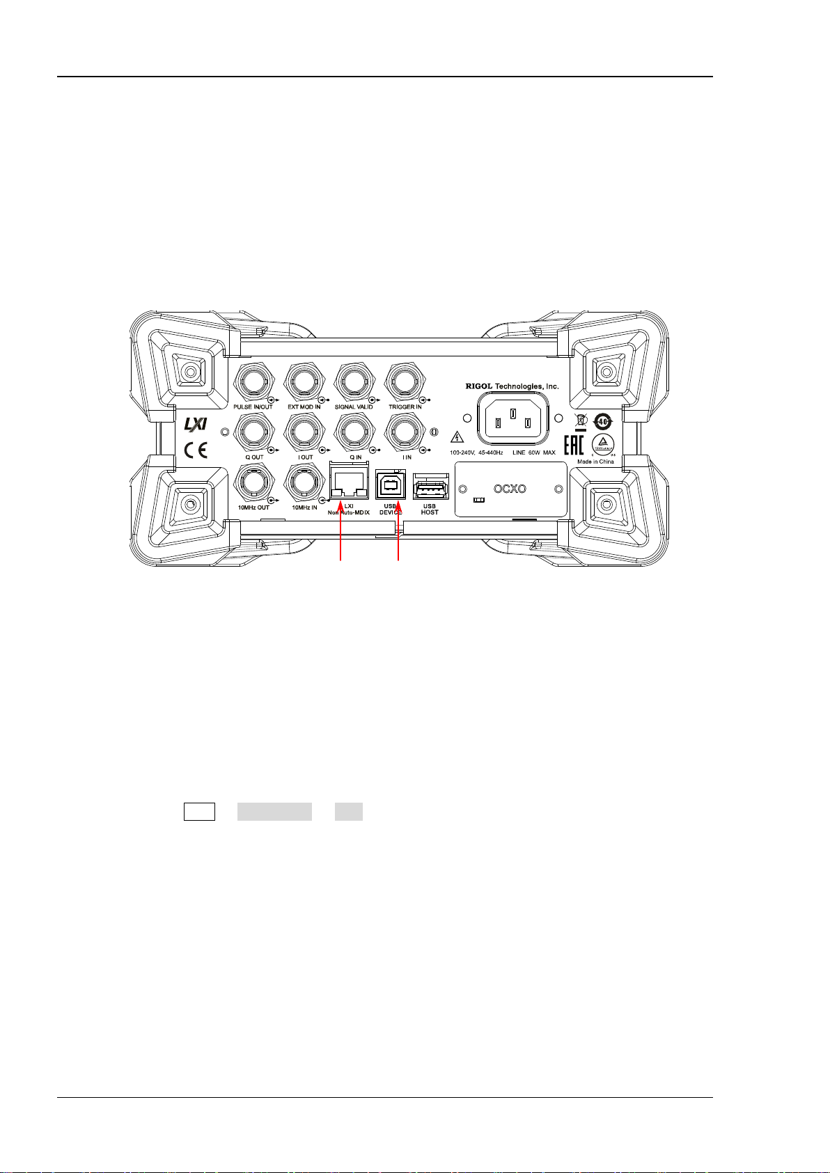
You can build the remote communication between DSG800 and the PC via USB or LAN interface.
Operating Steps:
1. Install the Ultra Sigma common PC software
Acquire the Ultra Sigma common PC software from www.rigol.com; then, install it according to the
instructions.
2. Connect the instrument and PC and configure the interface parameters of the instrument
DSG800 supports USB and LAN communication interfaces, as shown in the figure below.
LAN USB DEVICE
Figure 1-1 DSG800 Communication Interfaces
(1) Use the USB interface:
Connect the USB DEVICE interface at th e rear panel of DSG800 and the USB HOST interface of the
PC using a USB cable .
(2) Use the LAN interface:
Make sure that your PC is connected to the lo cal network.
Check whether your l ocal network supports DHCP or auto IP mode. If not, you need to
acquire the network interface parameters available, including the IP address, subnet mask,
gateway and DNS.
Connect DSG800 to the local network using a network cable.
Press Syst I/O Config LAN to configure the IP address, subnet mask, gateway and
DNS of the instrument.
3. Check whether the connection is successful
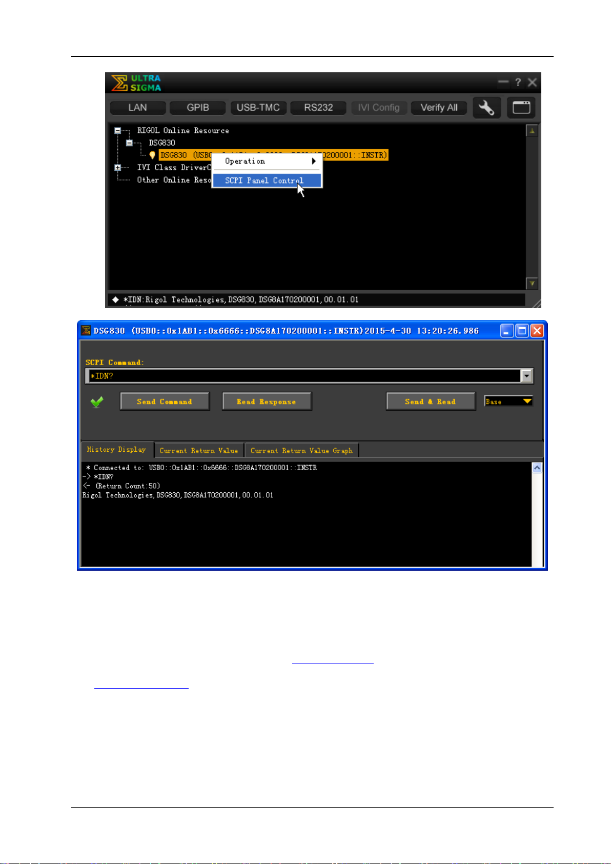
Start-up Ultra Sigma, sea rch for the RF signal generator resource, right-click the resource name and
select "SCPI Panel Contro l" from the pop-up menu. Enter the correct command in the pop-up SCPI
control panel and click Send Command, Read Response or Send&Read to check whether the
connection is successful, as shown in the figure on the next p age (take the USB interface as an
example).
1-2 DSG800 Programming Guide
Page 17
Chapter 1 Programming Overview RIGOL
Remote Control Methods
1. User-defined programming
You can program and control DSG800 usi ng the SCPI (Standard Commands for Programmable
Instruments) commands listed in chapter 2
(such as Visual C++, Visual Basic and LabVIEW). For the details, refer to the introductions in chapter 4
Programming Demos.
2. Send SCPI commands via PC software
You can use the PC software Ultra Sigma (provided by RIGOL) to send SCPI commands to control the
RF signal generator remotely.
DSG800 Programming Guide 1-3
Command System in various development environments
Page 18

RIGOL Chapter 1 Programming Overview
SCPI Command Overview
SCPI (Standard Comm ands for Programmable Instruments) is a standardized instrument programming
language that is based on the standard IEEE488.1 and IEEE488.2 and conforms to various standards (such
as the floating point operation rule in IEEE754 standard, ISO646 7-bit coded character for information
interchange (equivalent to ASCll programming)). This chapter describes the syntax, symbols, parameters
and abbreviation rules of the SCPI commands.
Syntax
SCPI commands present a hierarchical tree structure and have multiple sub-systems, each of which
contains a root keyword and one or more sub-keywords. The command string usually begins with ":"; the
keywords are separted by ":" and are followed by the parameter settings available; "?" is added at the end
of the command string to indicate query; space is used to separate the command and parameter.
For example,
:SYSTem:COMMunication:LAN:IP:ADDress <value>
:SYSTem:COMMunication:LAN:IP:ADDress?
SYSTem is the root keyword of the com mand above. COMMunication, LAN, IP and ADDress are the
second-level, third-level, forth-level and fifth-level keywords respectively. The command string begins with
":" which is also used to separate the multi-level keywords. <value> denotes the parameter available for
setting. "?" denotes query and the RF signal ge nerator returns the response information (the output value
or internal setting value of the instrument ) when receiving a query command. The
command :SYSTem:COMMunication:LAN:IP:ADDress and prarameter <value> are separated by a space.
"," is generally used for separating different parameters contained in the same command; for example,
[:SOURce]:SWEep:LIST:LIST? <Start>,<Count>
Symbol Description
The following four symbols are not the content of SCPI commands and will not be sent with the command;
but, they are usually used to describe the parameters in the commands.
1. Braces { }
Multiple optional parameters are enclosed in the braces and one of the parameters must be selected
when sending the co mmand.
2. Vertical Bar |
The vartical bar is used to separate multiple parameters. When you send a command, one of the
parameters must be selected. For example, the :SYSTem:LANGuage CHINese|E NGLish command.
3. Square Brackets [ ]
The contents (command keywords) enclosed in the square brackets are optional and will be executed
no matter whether they are omitted or not. For example, for the [:SOURce]:AM[:DEPTh]? command,
sending any of the four commands below can generate the same effect.
:AM?
:AM:DEPTh?
:SOURce:AM?
:SOURce:AM:DEPTh?
4. Triangle Brackets < >
The parameter enclosed in the triangle brack ets must be replaced by an effective value. For example,
send the [:SOURce]:FREQuency <value> command in :FREQuency 4MHz form.
1-4 DSG800 Programming Guide
Page 19

Chapter 1 Programming Overview RIGOL
Parameter Type
The parameters of the commands introduced in this manual contains 5 types: bool, integer, real number,
discrete and ASCII string.
1. Bool
The parameter could be OFF, ON, 0 or 1. For example, [:SOURce]:AM:STATe ON| OFF|1|0.
2. Integer
Unless otherwise noted, the parameter can be any integer within the effective value range. Note that
do not set the parameter to a decimal; otherwise, errors will occur. For example, in
the :SYSTem:BRIGhtness <value> command, <value> can be any integer from 1 to 8.
3. Real Number
Unless otherwise noted, the parameter can be any value within the effective value range.
For example, <value> in the [:SOURce]:AM:FREQuency <value> command can be any real number
from 10Hz to 100 kHz.
4. Discrete
The parameter could only be one of the specified values or characters. For example, in the
[:SOURce]:AM:WAVEform SINE|SQUA command, the parameter can only be SINE or SQUA.
5. ASCII String
The parameter should be the combinations of ASCII characters. For example, in the :MMEMory:SAVe
<file_name> command, <file_name> is the filena me of the file to be saved and can include Chinese
characters (a Chinese character occupies two bytes), English characters and numbers. The filename
cannot exceed 28 bytes.
Command Abb r eviation
All the commands are case-insensitive and you can use any of them. If abbreviation is used, all the capital
letters in the command must be written completely. For example, the :MMEMory:DISK:FORMat command
can be abbreviated to :MMEM:DISK:FORM.
DSG800 Programming Guide 1-5
Page 20

Page 21

Chapter 2 Command System RIGOL
Chapter 2 Command System
This chapter introduces the syntax, function, parameter and using instruction of each DSG800 command in
alphabetical (A to Z) order.
Main topics of this chapter:
IEEE488.2 Common Commands
:MMEMory Commands
:OUTPut Command
:SOURce Commands
:STATus Commands
:SYSTem Commands
:TRIGger Commands
:UNIT Command
DSG800 Programming Guide 2-1
Page 22

RIGOL Chapter 2 Command System
Description
Query the ID string of the instrument.
Technologies,DSG830,DSG8A170200001,00.01.01.
IEEE488.2 Common Commands
The IEEE488.2 common commands are used to query the basic information about the instrument or
execute common operations. These commands usually begin with "*", contain a 3-charac ter command
keyword and relate to the status register.
[1]
Command List
*IDN?
*TRG
*IDN?
Syntax *IDN?
Return Format The query returns the ID string of the instrument. For example, Rigol
*TRG
:
Syntax *TRG
Description Trigger a pulse modulation, RF sweep or IQ wavetable output immediately.
Related
Commands
[1]
Note
not included and you can refer to the complete introductions of the commands in the text according to the keywords.
: In the "Command List" in this manual, the parameters in the setting commands and the query commands are
:TRIGger:IQ[:IMMediate]
:TRIGger:PULSe[:IMMediate]
:TRIGger[:SWEep][:IMMediate]
2-2 DSG800 Programming Guide
Page 23

Chapter 2 Command System RIGOL
<path>.
Example
:MMEM:CAT? D:
:MMEMory Commands
The :MMEMory c ommands are used to store files to the internal or external memory of the instrument, read
or delete the specified file as well as query the disk information.
Command List:
:MMEMory:CATalog
:MMEMory:CATalog:LENGth
:MMEMory:COPY
:MMEMory:DATA:IQ
:MMEMory:DATA:IQ:LIST
:MMEMory:DELete
:MMEMory:DISK:FORMat
:MMEMory:DISK:INFormation
:MMEMory:FILEtype
:MMEMory:LDISk:SPACe
:MMEMory:LOAD
:MMEMory:MDIRectory
:MMEMory:MOVE
:MMEMory:PNAMe:EDIT
:MMEMory:PNAMe:STATe
:MMEMory:SAVe
:MMEMory:CATalog
Syntax :MMEMory:CATalog? <path>
Description Query all the files and folders under the specified path.
Parameter
Name Type Range Default
DSG800 Programming Guide 2-3
<path> ASCII string Valid path --
Explanation <path>: the local memory (D disk), external memory (E disk; when a USB
storage device is detected by the USB HOST interface at the rear panel) or the
subdirectory unde r the D or E disk.
The query returns a list of all the files and folders under the path specified by
Return Format NO.1 File Name: Rigol
NO.2 File Name: 4.STA
Page 24
RIGOL Chapter 2 Command System
Name
Type
Range
Default
<path>
ASCII string
Valid path
--
subdirectory unde r the D or E disk.
D disk*/
Syntax
:MMEMory:COPY <file_source>,<file_destination>
by <file_destination>.
be copied
operation fails.
Example
:MMEM:COPY D:\1.STA,D:\
:MMEMory:CATalog:LENGth
Syntax :MMEMory:CATalog:LENGth? <path>
Description Query the number of files and folders under the specified path.
Parameter
Explanation <path> can be the local memory (D disk), external memory (E disk; when a USB
storage device is detected by the USB HOST interface at the rear panel) or the
Return Format The query returns an integer. For example, 2.
Example
:MMEM:CAT:LENG? D: /*Query and r eturn the number of files and folders in the
:MMEMory:COPY
Description Copy the file or folder specified by <file_source> to the destination path specified
Parameter
Explanation <file_source> denotes the file or folder to be copied. The file or folder name
If the file or folder specified by <file_source> does not exist, the operation
If the destination path specified by <file_destination> does not exist, the copy
Name Type Range Default
<file_source> ASCII string
The name of the file or folder to
<file_destination> ASCII string Valid destination path --
must contain the path. <file_destination> denotes the destination path and
does not include the filename.
fails.
--
2-4 DSG800 Programming Guide
Page 25
Chapter 2 Command System RIGOL
Name
Type
Explanation
into the instrument.
When the IQ data file exceeds 64kB, you
and output the IQ waveform.
<num>
Integer
The number of IQ data pairs.
{,<i0>,<q0>
<in>,<qn>}
Decimal
IQ data pairs. Each data (for example, i0)
number of bytes occupied by the commas".
the IQ data to DSG800*/
instrument.
:MMEMory:DATA:IQ
Syntax
:MMEMory:DATA:IQ <file_n ame>,<flag>, <num>{,<i0>,<q0>…<in>,<qn>}
Description Save and download IQ waveform data to the instrument.
Parameter
<file_name> ASCII string
The name of the wavetable file downloaded
should download t he file packets separately.
0 denotes downloading the first data packet;
<flag> Discrete
1 denotes downloading the subsequent data
packets;
2 denotes downloading the last data packet
…
number
cannot exceed tw o bytes.
Explanation When sending the command, you should add the data block (start with #9 flag)
which denotes the total length of the IQ data before <i0>,<q0>…<in>,<qn>. For
example, #9000000011 denotes that the total len gth of the IQ data is 11 bytes. The
value is calculated by the formula "the number of bytes of the IQ data pairs + the
Example :MMEM:DATA:IQ test1,0,2,#9000000011 1,10,1 1,20
/*Save the two pairs of IQ data currently edited with the filename "test1" (the total
length of "1,10,11,20" is 11 bytes and is expressed by #9000000011) and download
:MMEMory:DATA:IQ:LIST
Syntax :MMEMory:DATA:IQ:LIST?
Description
Return Format The query returns the wavetable file list in the format of "wavetable filename
Query the wavetable files currently stored in the root directory (D: disk) of the
(*.arb),file size ". For example, wave2.arb,2180,wave3.arb,2516,.
DSG800 Programming Guide 2-5
Page 26

RIGOL Chapter 2 Command System
Syntax
:MMEMory:DELete <file_name>
Description
Delete the specified file or folder under the specified operation path.
Name
Type
Range
Default
be deleted
example, :MMEM:DEL D:\NEW\8.STA.
path*/
Syntax
:MMEMory:DISK :IN Format i on? <Disk>
Name
Type
Range
Default
<Disk>
ASCII string
D: (or LOCAL)
D: (or LOCAL)
Free:0.99 GB
Example
:MMEM:DISK:INF? D: /*The query returns the information of D disk*/
:MMEMory:DELete
Parameter
<file_name> ASCII string
The name of the file or folder to
Explanation This command is valid only when the specified file or folder exists under the
current operation path or the specified path.
<file_name> can be the name of a file or folder under the current operation
path or a file or folder name conta ining the specified path. For
Example :MMEM:DEL 8.STA /*Delete the file named "8.STA" under the current operation
:MMEMory:DISK:FORMat
Syntax :MMEMory:DISK:FORMat
Description Format the local disk (D disk).
:MMEMory:DISK:INFormation
Description Query the information of the local disk.
--
Parameter
Return Format The query returns the information of the local disk, including the disk na me, file
system, total space, used space and free space. For example,
Disk:D: (or Disk:LOCAL)
File Sys:FAT32
Total:1.0 GB
Used:512 KB
2-6 DSG800 Programming Guide
Page 27

Chapter 2 Command System RIGOL
:MMEMory:FILEtype?
Name
Type
Range
Default
type or save a new file of this file type.
ARB, FLACSV, SWPCSV, TRNCSV, SEGMENT, SEQLIST
or SEQCSV.
STATE*/
space". For example, Used:512 k,Free:1048064 k.
Syntax
:MMEMory:LOAD <file_name>
Description
Read the specified file in the specified operation path.
Name
Type
Range
Default
string
read
name containing the specified path. For example, MMEM:LOAD D:\NEW\2.STA.
path*/
:MMEMory:FILEtype
Syntax :MMEMory:FILEtype
ALL|STATe|ARB|FLACsv|SWPCsv|TRNCsv|SEGMent|SEQList|SEQCsv
Description Set the file type.
Query the current file type.
Parameter
ALL|STATe|ARB|FLACsv|S
WPCsv|TRNCsv|SEGMent|
Discrete
SEQList|SEQCsv
Explanation The file types available are all, state, Arb, flatness csv, sweep csv, train csv,
segment, seg list and seg csv.
After selecting the corresponding file type, you can view all the files of this file
Return Format The query returns ALL, STATE,
ALL|STATe|ARB|FLACsv|S
WPCsv|TRNCsv|SEGMent|
SEQList|SEQCsv
ALL
Example :MMEM:FILE S TATe /* Set the file type to "State"*/
:MMEM:FILE? /*Query the current file type and the query returns
:MMEMory:LDISk:SPACe
Syntax :MMEMory:LDISk:SPACe?
Description Query the space information of the local disk (D disk).
Return Format
The query returns the D disk sp ace information i ncluding the "Used space" an d "Free
:MMEMory:LOAD
Parameter
<file_name>
ASCII
Explanation This command is valid only when the specified file exists under the current
operation path or the specified path.
The name of the file to be
--
<file_name> can be the name of a file under the current operation path or a file
Example :MMEM:LOAD 2.STA /*Read the file named "2.STA" under the current operation
DSG800 Programming Guide 2-7
Page 28

RIGOL Chapter 2 Command System
Syntax
:MMEMory:MDIRect or y <di re ct ory_ na me >
Name
Type
Range
Default
created
specified pa th; for example, :MMEM:MDIR D:\1\NEW).
path*/
Syntax
:MMEMory:MOVE <file_source>,<file_destination>
Name
Type
Range
Default
exists under the current path, the rename ope ration fails.
Example
:MMEM:MOVE D:\1.STA, D:\2.STA
:MMEMory:MDIRectory
Description Create a new folder under the specified operation path.
Parameter
<directory_name> ASCII string
The name of the folder to be
Explanation The folder name can include Chinese characters (a Chinese character occupies
two bytes), English characters or numbers. The folder name cannot exceed 28
bytes.
If the name of the folder to be created already exists, this operation is invalid. At
this point, "The filename already exists" is displayed in the user interface.
<directory_name> can be a new folder name that does not contain the path
(denote creating a folder under the current o peration path) or a folder name
that contains the specified path (denote creating a new folder under the
Example :MMEM:MDIR NEW /*Create a folder named "NEW" under the current operation
:MMEMory:MOVE
Description Rename the file or folder specified by <file_source> as the destination file or folder
name specified by <file_destination>.
Parameter
--
<file_source>
ASCII string Valid file or folder name --
<file_destination>
Explanation The file or folder names specified by <file_source> and <file_destination>
must contain the path.
If the file or folder specified by <file_source> does not exist, the rename
operation fails.
If the destination file or folder name specified by <file_destination> already
2-8 DSG800 Programming Guide
Page 29

Chapter 2 Command System RIGOL
:MMEMory:PNAMe:EDIT?
Name
Type
Range
Default
<pre_name>
ASCII string
The filename prefix to be edited
--
Command
Name
Type
Range
Default
filename input box automatically when saving a file.
:MMEM:PNAM:STAT?
:MMEMory:PNAMe:EDIT
Syntax :MME Mo r y:P NA Me :ED I T <p re _nam e>
Description Edit and save the filename prefix.
Query the filename prefix saved.
Parameter
Explanation You can edit any filename prefix.
Return Format The query returns the filename prefix. For example, N.
Example :MMEM:PNAM:EDIT N /*Edit the filename pref ix as N*/
:MMEM:PNAM:EDIT? /*The query returns N*/
Related
:MMEMory:PNAMe:STATe
:MMEMory:PNAMe:STATe
Syntax :MMEMory:PNAMe:STATe ON|OFF|1|0
:MMEMory:PNAMe:STATe?
Description Turn on or off the filename prefix.
Query the current on/off state of the filename prefix.
Parameter
ON|OFF|1|0 Bool ON|OFF|1|0 OFF|0
Explanation ON|1: turn on the filename prefix edited.
OFF|0: turn off the filename prefix edited.
If the f ilename prefix is turned on, the prefix edited will be added to the
Return Format The query returns 0 or 1.
Example
:MMEM:PNAM:STATe ON
Related
:MMEMory:PNAMe:EDIT
Command
DSG800 Programming Guide 2-9
Page 30

RIGOL Chapter 2 Command System
Syntax
:MMEMory:SAVe <File_name>
Description
Save the file with the specified filename under the current operation path.
Name
Type
Range
Default
<file_name>
ASCII string
The name of the file to be saved
--
command will directly overwrite the original file.
"SET.STA" under the current operation path*/
:MMEMory:SAVe
Parameter
Explanation The filename can include Chinese characters (a Chinese character occupies two
bytes), English characters or numbers. T he filename cannot exceed 28 bytes.
When the curr ent path already contains a file with the same name, this
Example :MMEM:SAV SET.STA /*Save the current instrument state with the filename
2-10 DSG800 Programming Guide
Page 31

Chapter 2 Command System RIGOL
:OUTPut[:STATe]?
Return Format
The query returns 1 or 0.
:OUTPut Command
Command List:
:OUTPut
:OUTPut[:STATe]
Syntax :OUTPut[:STATe] ON|OFF|1|0
Description Turn on or off the RF output.
Query the on/off state of the RF output.
Explanation
Parameter
Name Type Range Default
ON|OFF|1|0 Bool ON|OFF|1|0 OFF|0
ON|1: turn on the RF output. At this point, the backlight of RF/on goes on.
OFF|0: turn off the R F output. At this point, the backlight of RF/on goes off.
Example :OUTP ON /*Turn on the RF output*/
:OUTP? /*The query returns 1*/
DSG800 Programming Guide 2-11
Page 32

RIGOL Chapter 2 Command System
:SOURce Commands
The :SOURce commands are used to set the related parameters of the main functions of the RF signal
generator including the frequency, level, flatness calibration, AM, FM/ØM, Pulse, SWEEP, LF output and so
on.
Command List:
[:SOURce]:AM Command Subsystem
[:SOURce]:CORRection Command Subsystem
[:SOURce]:FM Command Subsystem
[:SOURce]:FMPM:TYPE
[:SOURce]:FREQuency Command Subsystem
[:SOURce]:INPut:TRIGger:SLOPe
[:SOURce]:IQ Command Subsystem
[:SOURce]:LEVel Command Subsystem
[:SOURce]:LFOutput Command Subsystem
[:SOURce]:MODulation:STATe
[:SOURce]:PM Command Subsystem
[:SOURce]:PULM Command Subsystem
[:SOURce]:SWEep Command Subsystem
[:SOURce]:AM Command Subsystem
Command List:
[:SOURce]:AM[:DEPTh]
[:SOURce]:AM[:DEPTh]:STEP[:INCRement]
[:SOURce]:AM:EXT:COUP
[:SOURce]:AM:EXT:IMP
[:SOURce]:AM:FREQuency
[:SOURce]:AM:FREQuency:STEP[:INCRement]
[:SOURce]:AM:SOURce
[:SOURce]:AM:STATe
[:SOURce]:AM:WAVEform
2-12 DSG800 Programming Guide
Page 33

Chapter 2 Command System RIGOL
[:SOURce]:AM[:DEPTh]?
Name
Type
Range
Default
<value>
Real
0 to 100
50
a
m
sb
ΔP
asb
mΔP lg206 −=
using the [:SOURce]:AM[:DEPTh]:STEP[:INCRement] command.
:AM:DEPT?
Command
Name
Type
Range
Default
<value>
Real
0.1 to 50
10
modulation depth using the [:SOURce]:AM[:DEPTh] command.
AM:DEPT:STEP:INCR?
Command
[:SOURce]:AM[:DEPTh]
Syntax [:SOURce]:AM[:DEPTh] <value>
Description Set the AM modulation depth.
Query the AM modulation depth.
Parameter
Explanation
When "Int" modulation source is selected, the AM modulation depth (
amplitude difference (
following relation:
) between the carrier and sidebands satisfy the
.
<value> can also be expressed as percentage. For example, 80%.
After the modulation depth is set, you can rotate the knob to modify the
modulation depth at the current step. You can set and query the current step
Return Format The query returns the modulation depth. For example, 80.00.
Example
Related
:AM:DEPT 80
[:SOURce]:AM[:DEPTh]:STEP[:INCRement]
[:SOURce]:AM[:DEPTh]:STEP[:INCRement]
Syntax [:SOURce]:AM[:DEPTh]:STEP[:INCRement] <value>
[:SOURce]:AM[:DEPTh]:STEP[:INCRement]?
Description Set the AM modulation depth step.
) and
Query the AM modulation depth step.
Parameter
Explanation <value> can also be expressed as percentage. For example, 0.2%.
After the modulation depth step is set, you can rotate the knob to modify the
modulation depth at the current step. At this point, you can query or set the
Return Format The query returns the modulation depth st ep. For example, 0.20.
Example
Related
AM:DEPT:STEP:INCR 0.2
[:SOURce]:AM[:DEPTh]
DSG800 Programming Guide 2-13
Page 34

RIGOL Chapter 2 Command System
[:SOURce]:AM:EXT:COUP?
Name
Type
Range
Default
AC|DC
Discrete
AC|DC
AC
Return Format
The query returns AC or DC.
:AM:EXT:COUP?
Command
Command
[:SOURce]:AM:EXT:COUP
Syntax [:SOURce]:AM:EXT:COUP AC|DC
Description Set the coupling mode of AM external modulation.
Query the coupling mode of AM external modulation.
Parameter
Explanation AC: set the coupling mode of AM external modulation to "AC".
DC: set the coupling mode of AM external modulation to "DC".
When the modulation source of AM is set to "Int", this command is invalid.
Example :AM:EXT:COUP AC
Related
[:SOURce]:AM:SOURce
[:SOURce]:AM:EXT:IMP
Syntax [:SOURce]:AM:EXT:IMP 50|600|100k
[:SOURce]:AM:EXT:IMP?
Description Set the impedance of AM external modulation.
Query the impedance of AM external modulation.
Parameter
Explanation 50: set the impedance of AM external modulation to "50ohm".
600: set the impedance of AM external modulation to "600ohm".
100k: set the impedance of AM external modulation to "100kohm".
When the modulation source of AM is set to "Int", this command is invalid.
Return Format The query returns 50, 600 or 100k.
Example :AM:EXT:IMP 600
Name Type Range Default
50|600|100k Discrete 50|600|100k 100k
Related
2-14 DSG800 Programming Guide
:AM:EXT:IMP?
[:SOURce]:AM:SOURce
Page 35

Chapter 2 Command System RIGOL
[:SOURce]:AM:FREQuency?
Name
Type
Range
Default
(Square)
When the modulation source of AM is set to "Ext", this command is invalid.
:AM:FREQ?
[:SOURce]:AM:SOURce
[:SOURce]:AM:FREQuency:STEP[:INCRement]?
Name
Type
Range
Default
the modulation frequency using the [:SOURce]:AM:FREQuency command.
:AM:FREQ:STEP?
Command
[:SOURce]:AM:FREQuency
Syntax [:SOURce]:AM:FREQuen cy < value>
Description Set the AM modulation frequency.
Query the AM modulation frequency.
Parameter
<value> Real
10Hz to 100kHz (Sine)/10Hz to 20kHz
Explanation When <value> is set in "Number" form, the default unit is Hz; for example,
20000. In addition, <value> can a lso be set in "Number + Unit" form; for
example, 20kHz.
After the modulation frequency is set, you can rotate the knob to modify the
modulation frequency at the current step. You can set and query the current
step using the
[:SOURce]:AM:FREQuency:STEP[:INCRement] command.
Return Format The query returns the AM modulation frequency. For example, 20.00000kHz.
Example
Related
:AM:FREQ 20kHz
[:SOURce]:AM:FREQuency:STEP[:INCRement]
Commands
[:SOURce]:AM:FREQuency:STEP[:INCRement]
Syntax [:SOURce]:AM:FREQuency:STEP[:INCRement] <value>
10kHz
Description Set the AM modulation frequency step.
Query the AM modulation frequency step.
Parameter
<value> Real 1Hz to 50kHz 1kHz
Explanation When <value> is set in "Number" form, the default unit is Hz. In addition,
<value> can also be set in "Number + Unit" form; for example, 3.55kHz.
After the modulation frequency step is set, you can rotate the knob to modify
the modulation frequency at the current step. At this point, you can query or set
Return Format The query returns the AM modulation frequency step. For example, 3.55000kHz.
Example
Related
:AM:FREQ:STEP 3.55kHz
[:SOURce]:AM:FREQuency
DSG800 Programming Guide 2-15
Page 36

RIGOL Chapter 2 Command System
[:SOURce]:AM:SOURce?
Name
Type
Range
Default
modulation waveform of the modulating signal.
[:SOURce]:AM:WAVEform
[:SOURce]:AM:STATe?
[:SOURce]:AM:SOURce
Syntax [:SOURce]:AM:SOURce EXTernal|INTernal
Description Set the AM modulation source.
Query the AM modulation source.
Parameter
EXTernal|INTernal Discrete EXTernal|INTernal INTernal
Explanation EXTernal: set the modulation source to "Ext". At this point, the external
modulating signal is input from the [EXT MOD IN] connector.
INTernal: set the modulation source to "Int". At this point, the instrument
provides the modulati ng signal and you can set the modulation frequency and
Return Format The query returns the AM modulation source. For example, EXT.
Example :AM:SOUR EXT
:AM:SOUR?
Related
[:SOURce]:AM:FREQuency
Commands
[:SOURce]:AM:STATe
Syntax [:SOURce]:AM:STATe ON|OFF|1|0
Description Set the state of the AM switch.
Query the state of the AM switch.
Parameter
Explanation ON|1: turn on the AM switch to enable the AM function.
OFF|0: turn off the AM switch to disable the AM function.
Return Format The query returns 1 or 0.
Example :AM:STAT ON /*Turn on the AM switch*/
:AM:STAT? /*The query returns 1*/
Name Type Range Default
ON|OFF|1|0 Bool ON|OFF|1|0 OFF|0
2-16 DSG800 Programming Guide
Page 37

Chapter 2 Command System RIGOL
[:SOURce]:AM:WAVEform?
Name
Type
Range
Default
:AM:WAVE?
Command
[:SOURce]:AM:WAVEform
Syntax [:SOURce]:AM:WAVEform SINE|SQUA
Description Set the AM modulation waveform.
Query the AM modulation waveform.
Parameter
SINE|SQUA Discrete SINE|SQUA SINE
Explanation SINE: set the AM modulation waveform to "Sine".
SQUA: set the AM modulation waveform to "Square".
When the modulation source of AM is set to "Ext", this command is invalid.
Return Format The query returns SINE or SQUA.
Example
Related
:AM:WAVE SQUA
[:SOURce]:AM:SOURce
DSG800 Programming Guide 2-17
Page 38

RIGOL Chapter 2 Command System
example, 5.
Syntax
[:SOURce]:CORRection:FLATness:LIST? <Start>,<Count>
Name
Type
Range
Default
<Count>
Integer
1 to the total number of rows in the current list
--
from the 2nd row of the flatness calibration list*/
Command
[:SOURce]:CORRection Command Subsystem
Command List:
[:SOURce]:CORRection:FLATness:COUNt
[:SOURce]:CORRection:FLATness:LIST
[:SOURce]:CORRection:FLATness[:STATe]
[:SOURce]:CORRection:FLATness:COUNt
Syntax [:SOURce]:CORRection:FLATness:COUNt?
Description Query the number of points in the current flatness calibration list.
Return Format
The query returns the number of points in the flatness calibration list in integer. For
[:SOURce]:CORRection:FLATness:LIST
Description Query the flatness calibration list data within the specified range.
Parameter
<Start> Integer 1 to the total number of rows in the current list --
Explanation <Start>: the number of the start row of the data to be acquired.
<Count>: the total number of rows of the data to be acquired.
Return Format The query returns the flatness calibration list data acquired. For example,
NO.1:3040000 00. 00 00 00 , 7.4 50 000
NO.2:8000000 00. 00 00 00 , -17.799999
Example
:CORR:FLAT:LIST? 2,2 /*Query and return two rows of calibration data starting
Related
[:SOURce]:CORRection:FLATness:COUNt
2-18 DSG800 Programming Guide
Page 39

Chapter 2 Command System RIGOL
[:SOURce]:CORRection:FLATness[:STATe]?
Name
Type
Range
Default
ON|OFF|1|0
Bool
ON|OFF|1|0
OFF|0
[:SOURce]:CORRection:FLATness[:STATe]
Syntax [:SOURce]:CORRection:FLATness[:STATe] ON|OFF|1|0
Description Turn on or off the flatness calibration switch.
Query the state of the flatness calibration switch.
Parameter
Explanation ON|1: turn on the flatness calibration switch.
OFF|0: turn off the flatness calibration switch.
Return Format The query returns 1 or 0.
Example :CORR:FLAT ON /*Turn on the flatness calibration switch*/
:CORR:FLAT? /*The query returns 1*/
DSG800 Programming Guide 2-19
Page 40
RIGOL Chapter 2 Command System
[:SOURce]:FM[:DEViation]?
Name
Type
Range
Default
1MHz
[:SOURce]:FM[:DEViation]:STEP[:INCRement] command.
Return Format
The query returns the FM frequency deviation. For example, 20.00000kHz.
:FM:DEV?
Command
[:SOURce]:FM Command Subsystem
Command List:
[:SOURce]:FM[:DEViation]
[:SOURce]:FM[:DEViation]:STEP[:INCRement]
[:SOURce]:FM:EXT:COUP
[:SOURce]:FM:EXT:IMP
[:SOURce]:FM:FREQuency
[:SOURce]:FM:FREQuency:STEP[:INCRement]
[:SOURce]:FM:SOURce
[:SOURce]:FM:STATe
[:SOURce]:FM:WAVEform
[:SOURce]:FM[:DEViation]
Syntax [:SOURce]:FM[:DEViation] <value>
Description Set the FM frequency deviation.
Query the FM frequency deviation.
Parameter
<value> Real
100mHz to
10kHz
Explanation When <value> is set in "Number" form, the default unit is Hz; for example,
20000. In addition, <value> can a lso be set in "Number + Unit" form; for
example, 20kHz.
After the frequency deviation is set, you can rotate the knob to modify the
deviation at the current step. You can set and query the current step using the
Example :FM:DEV 20kHz
Related
[:SOURce]:FM[:DEViation]:STEP[:INCRement]
2-20 DSG800 Programming Guide
Page 41

Chapter 2 Command System RIGOL
[:SOURce]:FM[:DEViation]:STEP[:INCRement]?
Name
Type
Range
Default
<value>
Real
10mHz to 500kHz
1kHz
frequency deviation using t he [:SOURce]:FM[:DEViation] command.
:FM:STEP:INCR?
Command
[:SOURce]:FM:EXT:COUP?
Name
Type
Range
Default
Command
[:SOURce]:FM[:DEViation]:STEP[:INCRement]
Syntax [:SOURce]:FM[:DEViation]:STEP[:INCRement] <value>
Description Set the FM frequency deviation step.
Query the FM frequency deviation step.
Parameter
Explanation When <value> is set in "Number" form, the default unit is Hz; for example,
5000. In addition, <value> can also be set in "Number + Unit" form; for
example, 5kHz.
After the frequency deviation step is set, you can rotate th e kn ob to modif y the
deviation at the current step. At this point, You can query or set the current
Return Format The query returns the FM frequency deviation step. For example, 5.00000kHz.
Example
Related
:FM:STEP:INCR 5kHz
[:SOURce]:FM[:DEViation]
[:SOURce]:FM:EXT:COUP
Syntax [:SOURce]:FM:EXT:COUP AC|DC
Description Set the coupling mode of FM external modulation.
Query the coupling mode of FM external modulation.
Parameter
Explanation AC: set the coupling mode of FM external modulation to "AC".
DC: set the coupling mode of FM external modulation to "DC".
When the modulation source of FM is set to "Int", this command is invalid.
Return Format The query returns AC or DC.
AC|DC Discrete AC|DC AC
Example :FM:EXT:COUP AC
:FM:EXT:COUP?
Related
[:SOURce]:FM:SOURce
DSG800 Programming Guide 2-21
Page 42

RIGOL Chapter 2 Command System
[:SOURce]:FM:EXT:IMP?
Name
Type
Range
Default
50|600|100k
Discrete
50|600|100k
100k
Return Format
The query returns 50, 600 or 100k.
:FM:EXT:IMP?
Command
[:SOURce]:FM:FREQuency?
Name
Type
Range
Default
(Square)
When the modulation source of FM is set to "Ext", this command is invalid.
Return Format
The query returns the FM modulation frequency. For example, 20.00000kHz.
:FM:FREQ?
[:SOURce]:FM:SOURce
[:SOURce]:FM:EXT:IMP
Syntax [:SOURce]:FM:EXT:IMP 50|600|100k
Description Set the impedance of FM external modulation.
Query the impedance of FM external modulation.
Parameter
Explanation 50: set the impedance of FM external modulation to "50ohm".
600: set the impedance of FM external modulation to "600ohm".
100k: set the impedance of FM external modulation to "100 kohm".
When the modulation source of FM is set to "Int", this command is invalid.
Example :FM:EXT:IMP 600
Related
[:SOURce]:FM:SOURce
[:SOURce]:FM:FREQuency
Syntax [:SOURce]:FM:FREQuency < value>
Description Set the FM modulation frequency.
Query the FM modulation frequency.
Parameter
<value> Real
Explanation When <value> is set in "Number" form, the default unit is Hz; for example,
20000. In addition, <value> can al so be set in "Number + Unit" form; for
example, 20kHz.
After the modulation frequency is set, you can rotate the knob to modify the
modulation frequency at the current step. At this point, you can set and query
the current step using the
command.
10Hz to 100kHz (Sine)/10Hz to 20kHz
[:SOURce]:FM:FREQuency:STEP[:INCRement]
10kHz
Example :FM:FREQ 20kHz
Related
[:SOURce]:FM:FREQuency:STEP[:INCRement]
Commands
2-22 DSG800 Programming Guide
Page 43

Chapter 2 Command System RIGOL
[:SOURce]:FM:FREQuency:STEP[:INCRement]?
Name
Type
Range
Default
the modulation frequency using the [:SOURce]:FM:FREQuency command.
:FM:FREQ:STEP?
Command
[:SOURce]:FM:SOURce?
Name
Type
Range
Default
EXTernal|INTernal
Discrete
EXTernal|INTernal
INTernal
modulation waveform of the modulating signal.
Return Format
The query returns the FM modulation source. For example, INT.
:FM:SOUR?
[:SOURce]:FM:WAVEform
[:SOURce]:FM:FREQuency:STEP[:INCRement]
Syntax [:SOURce]:FM:FREQuency:STEP[:I NCRement ] < value>
Description Set the FM modulation frequency step.
Query the FM modulation frequency step.
Parameter
<value> Real 1Hz to 50kHz 1kHz
Explanation When <value> is set in "Number" form, the default unit is Hz; for example,
5000. In addition, <value> can also be set in "Number + Unit" form; for
example, 5kHz.
After the modulation frequency step is set, you can rotate the knob to modify
the modulation frequency at the current step. At this point, you can query or set
Return Format The query returns the FM modulation frequency step. For example, 5.00000kHz.
Example
Related
:FM:FREQ:STEP 5kHz
[:SOURce]:FM:FREQuency
[:SOURce]:FM:SOURce
Syntax [:SOURce]:FM:SOURce EXTernal|INTernal
Description Set the FM modulation source.
Query the FM modulation source.
Parameter
Explanation EXTernal: set the modulation source to "Ext". At this point, the external
modulating signal is input from the [EXT MOD IN] connector.
INTernal: set the modulat ion source to "Int". At this point, the instrument
provides the modulati ng signal and you can set the modulation frequency and
Example :FM:SOUR INT
Related
Commands
[:SOURce]:FM:FREQuency
DSG800 Programming Guide 2-23
Page 44

RIGOL Chapter 2 Command System
[:SOURce]:FM:STATe?
Name
Type
Range
Default
ON|OFF|1|0
Bool
ON|OFF|1|0
OFF|0
Name
Type
Range
Default
:FM:WAVE?
Command
[:SOURce]:FM:STATe
Syntax [:SOURce]:FM:STATe ON|OFF|1|0
Description Set the state of the FM switch.
Query the state of the FM switch.
Parameter
Explanation ON|1: turn on the FM switch to enable the FM function.
OFF|0: turn off the FM switch to disa ble the FM function.
Return Format The query returns 1 or 0.
Example :FM:STAT ON /*Turn on the FM switch*/
:FM:STAT? /*The query re turns 1*/
[:SOURce]:FM:WAVEform
Syntax [:SOURce]:FM:WAVEform SINE| SQ UA
[:SOURce]:FM:WAVEform?
Description Set the FM modulation waveform.
Query the FM modulation waveform.
Parameter
SINE|SQUA Discrete SINE|SQUA SINE
Explanation SINE: set t he FM modulation waveform to "Sine".
SQUA: set the FM modulation waveform t o "Square".
When the modulation source of FM is set to "Ext", this command is invalid.
Return Format The query returns SINE or SQUA.
Example
Related
:FM:WAVE SQUA
[:SOURce]:FM:SOURce
2-24 DSG800 Programming Guide
Page 45

Chapter 2 Command System RIGOL
[:SOURce]:FMPM:TYPE?
Name
Type
Range
Default
Return Format
The query returns FM or PM.
:FMPM:TYPE?
[:SOURce]:FMPM:TYPE
Syntax [:SOURce]:FMPM:TYPE FM|PM
Description Set the current modulation type to FM or ØM.
Query the current modulation type.
Parameter
FM|PM Discrete FM|PM PM
Explanation FM: set the current modulation type to "FM".
PM: set the curr ent modulation type to "ØM".
Example :FMPM:TYPE FM
DSG800 Programming Guide 2-25
Page 46

RIGOL Chapter 2 Command System
Name
Type
Range
Default
the [:SOURce]:FREQuency:STEP command.
Command
[:SOURce]:FREQuency Command Subsystem
Command List:
[:SOURce]:FREQuency
[:SOURce]:FREQuency:STEP
[:SOURce]:FREQuency
Syntax [:SOURce]:FREQuency <value>
[:SOURce]:FREQuency?
Description Set the frequency of the RF signal.
Query the frequenc y of the RF signal.
Parameter
<value> Real 9kHz to 3GHz 3GHz
Explanation When <value> is set in "Number" form, the default unit is Hz; for example,
4000000. In addition, <value> can also be se t in "Number + Unit" form; for
example, 4MHz.
After the RF frequency is set, you can rotate the knob to modify the frequency
at the current step. At this point, you can set and query the current step using
Return Format The query returns the frequency of the RF signal. For example, 4.00000000MHz.
Example :FREQ 4MHz
:FREQ?
Related
[:SOURce]:FREQuency:STEP
2-26 DSG800 Programming Guide
Page 47

Chapter 2 Command System RIGOL
[:SOURce]:FREQuency:STEP?
<value>
Real
10mHz to 1GHz
100MHz
using the [:SOURce]:FREQuency command.
Return Format
The query returns the RF frequency step. For example, 3.00000kHz.
Command
rear panel.
[:SOURce]:FREQuency:STEP
Syntax [:SOURce]:FREQuency:STEP <value>
Description Set the RF frequency step.
Query the RF frequency step.
Parameter
Name Type Range Default
Explanation When <value> is set in "Number" form, the default unit is Hz; for example,
3000. In addition, <value> can also be set in "Number + Unit" form; for
example, 3kHz.
After the RF frequency step is set, you can rotate the knob to modify the
frequency at the current step. At this point, you can query or set the frequency
Example :FREQ:STEP 3kHz
:FREQ:STEP?
Related
[:SOURce]:FREQuency
[:SOURce]:INPut:TRIGger:SLOPe
Syntax [:SOURce]:INPut:TRIGger:SLOPe POSitive|NEGative
[:SOURce]:INPut:TRIGger:SLOPe?
Description Set the polarity of the external trigger input signal.
Query the polarity of the external trigger input signal.
Parameter
Explanation
This command is valid only when the trigger mode of SWEEP is set to "Ext".
Name Type Range Default
POSitive|NEGative Discrete POSitive|NEGative POSitive
The external trigger signal is input from the [TRIGGER IN] connector at the
Return Format The query returns POS or NEG.
Example :INP:TRIG:SLOP POS
:INP:TRIG:SLOP?
DSG800 Programming Guide 2-27
Page 48

RIGOL Chapter 2 Command System
[:SOURce]:IQ Command Subsystem
Command List
[:SOURce]:IQ:BASeout:LEVel
[:SOURce]:IQ:BASeout:LEVel:STEP
[:SOURce]:IQ:BASeout:STATe
[:SOURce]:IQ:MODe
[:SOURce]:IQ:MODe:STATe
[:SOURce]:IQ:SAMPle
[:SOURce]:IQ:SAMPle:STEP
[:SOURce]:IQ:TRIGger:ARB
[:SOURce]:IQ:TRIGger:DELay
[:SOURce]:IQ:TRIGger:DELay:STEP
[:SOURce]:IQ:TRIGger:DURation
[:SOURce]:IQ:TRIGger:DURation:STEP
[2]
:
[:SOURce]:IQ:TRIGger:DURation:UNIT
[:SOURce]:IQ:TRIGger:INHibit
[:SOURce]:IQ:TRIGger:INHibit:STEP
[:SOURce]:IQ:TRIGger:MODe
[:SOURce]:IQ:TRIGger:OPTMode
[:SOURce]:IQ:TRIGger:SEGMent:CURRent?
[:SOURce]:IQ:TRIGger:SEGMent:EXECute
[:SOURce]:IQ:TRIGger:SEGMent:MODE
[:SOURce]:IQ:TRIGger:SEGMent:NEXT
[2]
Note
Otherwise, the command settings are invalid.
: If you want to use the IQ-related commands, please order RF signal generators with the DSG800-IQ option.
2-28 DSG800 Programming Guide
Page 49

Chapter 2 Command System RIGOL
[:SOURce]:IQ:BASeout:LEVel?
Name
Type
Range
Default
current step using the [:SOURce]:IQ:BASeout:LEVel:STEP command.
1.100000.
:IQ:BAS:LEV?
Command
[:SOURce]:IQ:BASeout:LEVel:STEP?
<value>
Real
0.01V to 0.5V
0.1V
[:SOURce]:IQ:BASeout:LEVel command.
:IQ:BAS:LEV:STEP?
Command
[:SOURce]:IQ:BASeout:LEVel
Syntax [:SOURce]:IQ:BASeout:LEVel <value>
Description Set the baseband output amplitude.
Query the baseband outp ut amplitude.
Parameter
<value> Real 20mV to 1.5V 1V
Explanation When <value> is set in "Number" form, the default unit is V. Besides, <value>
can also be set in "Number + Unit" form; for example, 1.1V.
The default uni t of the return value is V.
After the baseband output a mplitude is set, you can rotate the knob to modify
the amplitude at the current step. At this point, you can set and que ry the
Return Format The query returns the amplitude of the baseband output signal. For example,
Example :IQ:BAS:LEV 1.1
Related
[:SOURce]:IQ:BASeout:LEVel:STEP
[:SOURce]:IQ:BASeout:LEVel:STEP
Syntax [:SOURce]:IQ:BASeout :LE Vel:STEP < value>
Description Set the baseband output amplitude step.
Query the baseband output amplitude step.
Parameter
Explanation When <value> is set in "Number" form, the default unit is V. Besides, <value>
The default uni t of the return value is V.
After the baseband output amplitude step is set, you can rotate the knob to
Return Format The query returns the baseband output amplitude step. For example, 0.200000.
Name Type Range Default
can also be set in "Number + Unit" form; for example, 0.2V.
modify the baseband output amplitude at the current step. At this point, you can
query or set the ba seband output amplitude using the
Example
Related
:IQ:BAS:LEV:STEP 0.2
[:SOURce]:IQ:BASeout:LEVel
DSG800 Programming Guide 2-29
Page 50

RIGOL Chapter 2 Command System
[:SOURce]:IQ:BASeout:STATe?
Name
Type
Range
Default
[:SOURce]:IQ:MODe?
Name
Type
Range
Default
connectors at the rear panel respectively.
:IQ:MOD?
[:SOURce]:IQ:BASeout:STATe
Syntax [:SOURce]:IQ:BASeout:STATe ON|OFF|1|0
Description Set the state of the baseband output switch.
Query the state of the baseband output switch.
Parameter
ON|OFF|1|0 Bool ON|OFF|1|0 OFF|0
Explanation ON|1: turn on the baseband output switch.
OFF|0: turn off the baseband output switch.
Return Format The query returns 1 or 0.
Example :IQ:BAS:STAT ON /*Turn on the baseband output switch*/
:IQ:BAS:STAT? /*The query returns 1*/
[:SOURce]:IQ:MODe
Syntax [:SOURce]:IQ:MODe INTernal|EXTernal
Description Set the IQ modulation source.
Query the IQ modula tion source.
Parameter
INTernal|EXTernal Discrete INTernal|EXTernal INTernal
Explanation INTernal: select "Int" modulation source. At this point, the modulating signal is
provided by the built-in baseband generator (wavetable) of the instrument. In
addition, if the IQ modulation switch is turned on, the baseband output switch
will be turned on automatically. The RF signal generator can output the I
(In-Phase) components and Q (Quadrature Phase) components of the IQ
modulation baseband signal from the [I OUT] and [Q OUT] connectors at the
rear panel respectively.
EXTernal: select "Ext" modulation source. At this point, the In-Phase and
Quadrature Phase b aseband sign als of IQ modulation are input from the [I IN]
and [Q IN] connectors at the rear panel respectively. In addition, when the
baseband output switch is turned on, the In-Phase and Quadrature Phase
components of the I/Q modulation baseband signal generat ed by the built-in
baseband generator (wavetable) can be output from the [I OUT] and [Q OUT]
Return Format The query returns the IQ m odulation source. For example, INT.
Example
Related
:IQ:MOD INT
[:SOURce]:IQ:BASeout:STATe
Command
2-30 DSG800 Programming Guide
Page 51

Chapter 2 Command System RIGOL
[:SOURce]:IQ:MODe:STATe?
Name
Type
Range
Default
ON|OFF|1|0
Bool
ON|OFF|1|0
OFF|0
Return Format
The query returns 1 or 0.
[:SOURce]:IQ:SAMPle?
Name
Type
Range
Default
<value>
Real
1kHz to 100MHz
1MHz
the [:SOURce]:IQ:SAMPle:STEP command.
:IQ:SAMP?
Command
[:SOURce]:IQ:MODe:STATe
Syntax [:SOURce]:IQ:MODe:STATe ON|OFF|1|0
Description Set the state of the IQ modulation switch.
Query the state of the IQ modulation switch.
Parameter
Explanation ON|1: enable the IQ modulation functio n.
OFF|0: disable the IQ modulation function.
Example :IQ:MOD:STAT ON /*Enable the IQ modulation function*/
:IQ:MOD:STAT? /*The query returns 1*/
[:SOURce]:IQ:SAMPle
Syntax [:SOURce]:IQ:SAMPle <value>
Description Set the sample rate of the IQ wavetable output.
Query the sample rate of the IQ wavetable output.
Parameter
Explanation When <value> is set in "Number" form, the default unit is Hz; for example,
3000. In addition, <value> can also be set in "Number + Unit" form; for
example, 3kHz.
The default uni t of the return value is Hz.
After the sample rate is set, you can rotate the knob to modify the sample rate
at the current step. At this point, you can set and query the current step using
Return Format The query returns the sample rate of the IQ wavetable output. For example, 3000.
Example
Related
:IQ:SAMP 3kHz
[:SOURce]:IQ:SAMPle:STEP
DSG800 Programming Guide 2-31
Page 52

RIGOL Chapter 2 Command System
or set the sample rate using the [:SOURce]:IQ:SAMPle command.
3000.
Command
and wait for the next trigger.
[:SOURce]:IQ:SAMPle:STEP
Syntax [:SOURce]:IQ:SAMPle:STEP <value>
[:SOURce]:IQ:SAMPle:STEP?
Description Set the sample rate step of the IQ wavetable output.
Query the sample rate step of the IQ wavetable output.
Parameter
Name Type Range Default
<value> Real 1Hz to 10MHz 1MHz
Explanation When <value> is set in "Number" form, the default unit is Hz; for example,
3000. In addition, <value> can also be set in "Number + Unit" form; for
example, 3kHz.
The default uni t of the return value is Hz.
After the sample rate step of IQ wavetable output is set, you can rotate the
knob to modify the sample rate at the current step . At this p oint, you can query
Return Format The query returns the sample rate step of the IQ wavetable output. For example,
Example :IQ:SAMP:STEP 3kHz
:IQ:SAMP:STEP?
Related
[:SOURce]:IQ:SAMPle
[:SOURce]:IQ:TRIGger:ARB
Syntax [:SOURce]:IQ:TRIGger:ARB
Description Stop the waveform output manually.
Explanation
When the operation mode after the IQ w avetable is triggered is set to "Arm Auto" or
"Arm Retrig", you need to use thi s command to sto p the wa veform output manually
Related
[:SOURce]:IQ:TRIGger:OPTMode
Command
2-32 DSG800 Programming Guide
Page 53

Chapter 2 Command System RIGOL
[:SOURce]:IQ:TRIGger:DELay?
Name
Type
Range
Default
N
d
T
a
S
a
d
d
S
N
T =
[:SOURce]:IQ:TRIGger:DELay:STEP command.
:IQ:TRIG:DEL?
[:SOURce]:IQ:TRIGger:MODe
[:SOURce]:IQ:TRIGger:DELay:STEP?
Name
Type
Range
Default
<value>
Integer
1 to 10000
1
[:SOURce]:IQ:TRIGger:DELay command.
:IQ:TRIG:DEL:STEP?
Command
[:SOURce]:IQ:TRIGger:DELay
Syntax [:SOURce]:IQ:TRIGger:DELay <value>
Description Set the ext ernal trigger delay of the IQ modulation baseband signal.
Query the external trigger delay of the IQ modulation baseband signal.
Parameter
<value> Integer 0 to 65535 0
Explanation The external delay refers to the delay of the response to a trigger when the
external trigger signal is received.
This command is valid only when "Ext" trigge r mode is selected. Wherein,
<value> describes the number of points (
obtained according to the current sample rate (
). The actual time (
d
):
After the trigger delay is set, you can rotate the knob to modif y the dela y at the
current step. At this poi nt, you can set and query the current step using the
) can be
.
Return Format The query returns the external trigger delay. For example, 300.
Example
Related
:IQ:TRIG:DEL 300
[:SOURce]:IQ:TRIGger:DELay:STEP
Commands
[:SOURce]:IQ:TRIGger:DELay:STEP
Syntax [:SOURce]:IQ:TRIGger :DE L ay:STE P < value>
Description Set the ext ernal trigger delay step of the IQ modulation baseband signal.
Query the external trigger delay step of the IQ modulation baseband signal.
Parameter
Explanation After the trigger delay step is set, you can rotate the knob to modify the trigger delay
at the current step. At this point, you can query or set the trigger delay using the
Return Format The query returns the external trigger delay step. For example, 20.
Example
Related
:IQ:TRIG:DEL:STEP 20
[:SOURce]:IQ:TRIGger:DELay
DSG800 Programming Guide 2-33
Page 54

RIGOL Chapter 2 Command System
[:SOURce]:IQ:TRIGger:DURation?
Name
Type
Range
Default
<value>
Integer
1 to 65535
1
r
N
r
T
a
S
arr
SN T =
[:SOURce]:IQ:TRIGger:DURation:STEP command.
:IQ:TRIG:DUR?
[:SOURce]:IQ:TRIGger:OPTMode
[:SOURce]:IQ:TRIGger:DURation:STEP?
<value>
Integer
1 to 10000
1
[:SOURce]:IQ:TRIGger:DURation command.
:IQ:TRIG:DUR:STEP?
[:SOURce]:IQ:TRIGger:DURation
Syntax [:SOURce]:IQ:TRIGger:DURation <value>
Description Set the duration of the signal in single trigger.
Query the duration of the signal in single trigger.
Parameter
Explanation This command is valid only when "Single" operation mode is selected. Wherein,
<value> describes the number of points (
). The actual time (
) can be
obtained according to the current sample rate (
):
After the duration is set, you can rotate the knob to modify the duration at the
current step. At this poi nt, you can set and query the current step using the
Return Format The query returns the duration of a single signal output. For example, 4000.
Example
Related
:IQ:TRIG:DUR 4000
[:SOURce]:IQ:TRIGger:DURation:STEP
Commands
[:SOURce]:IQ:TRIGger:DURation:STEP
Syntax [:SOURce]:IQ:TRIGger:DURation:STEP <value>
Description Set the duration step.
Query the duration step.
Parameter
Name Type Range Default
.
Explanation After the duration step is set, you can rotate the knob to modify the duration at the
current step. At this point, you can query or set the duration using the
Return Format The query returns the durat ion step. For example, 500.
Example
Related
:IQ:TRIG:DUR:STEP 500
[:SOURce]:IQ:TRIGger:DURation
Command
2-34 DSG800 Programming Guide
Page 55

Chapter 2 Command System RIGOL
[:SOURce]:IQ:TRIGger:DURation:UNIT?
example, SAMPLES.
[:SOURce]:IQ:TRIGger:INHibit?
Name
Type
Range
Default
<value>
Integer
0 to 65535
0
i
N
i
T
a
S
aii
SN T =
[:SOURce]:IQ:TRIGger:INHibit:STEP command.
Return Format
The query returns t he trigger inhibit. For example, 5000.
:IQ:TRIG:INH?
[:SOURce]:IQ:TRIGger:MODe
[:SOURce]:IQ:TRIGger:DURation:UNIT
Syntax [:SOURce]:IQ:TRIGger:DURation:UNIT SEQUENCE|SAMPLES
Description Set the duration unit o f the IQ wavetable in "Single" trigger.
Query the duration unit of the IQ wavetable in "Single" trigger.
Parameter
SEQUENCE|SAMPLES Discrete SEQUENCE|SAMPLES SAMPLES
Name Type Range Default
Explanation SEQUENCE: trigger by the waveform segment.
SAMPLES: trigger by the data point.
Return Format
The query returns the duration unit of the IQ wavetable in "Single" trigger. For
Example :IQ: TR IG :D UR : UNI T SAMP L E S
:IQ:TRIG:DUR:UNIT?
Related
[:SOURce]:IQ:TRIGger:OPTMode
Command
[:SOURce]:IQ:TRIGger:INHibit
Syntax [:SOURce]:IQ:TRIGger:INHibit <value>
Description Set the trigg er inhibit of the IQ modulation baseband signal.
Query the trigger inhibit of the IQ modulation baseband signal.
Parameter
Explanation Trigger inhibit refers to the time from when a trigger signal is received to when
the instrument receives the next trigger signal.
This command is valid only when "Ext" trigge r mode is selected. <value>
describes the number of points (
according to the current sample rate (
). The actual time (
):
) can be obtained
.
After the trigger inhibit is set, you can rotate the knob to modify the inhibit at
the current step. At this point, you can set and query the current step using the
Example :IQ:TRIG:INH 5000
Related
[:SOURce]:IQ:TRIGger:INHibit:STEP
Commands
DSG800 Programming Guide 2-35
Page 56

RIGOL Chapter 2 Command System
[:SOURce]:IQ:TRIGger:INHibit:STEP?
<value>
Integer
1 to 10000
1
the [:SOURce]:IQ:TRIGger:INHibit command.
Command
[:SOURce]:IQ:TRIGger:INHibit:STEP
Syntax [:SOURce]:IQ:TRIGger:INHibit:STEP <value>
Description Set the trigg er inhibit step.
Query the trigger inhibit step.
Parameter
Name Type Range Default
Explanation After the trigger inhibit step is set, you can rotate the knob to modify the trigger
inhibit at the current step. At this point, you can query or set the trigger inhibit using
Return Format The query returns the trigger inhibit step. For example, 555.
Example :IQ:TRIG:INH:STEP 555
:IQ:TRIG:INH:STEP?
Related
[:SOURce]:IQ:TRIGger:INHibit
2-36 DSG800 Programming Guide
Page 57

Chapter 2 Command System RIGOL
[:SOURce]:IQ:TRIGger:MODe?
Name
Type
Range
Default
AUTO|KEY|BUS|EXT
Discrete
AUTO|KEY|BUS|EXT
AUTO
Inhibit".
example, KEY.
:IQ:TRIG:MOD?
:TRIGger:IQ[:IMMediate]
[:SOURce]:IQ:TRIGger:MODe
Syntax [:SOURce]:IQ:TRIGger:MODe AUTO|KEY|BUS|EXT
Description Set the trigger mode of the IQ modulation baseband output.
Query the trigger mode of the IQ modulation baseband output.
Parameter
Explanation AUTO: select "Auto" trigger mode. At this point, the RF signal generator fulfills
the trigger condition at any time and will output the IQ baseband signal
continuously.
KEY: select "Key" trigger mode. At this point, the instrument will output the
baseband signal each time Key Trig is pressed.
BUS: select "Bus" trigger mode. At this point, the instrument will o utput the
baseband signal each time the
sent.
EXT: select "Ext" trigger mode. At this point, the RF signal generator receives
the external trigger signal input from the [TRIGGER IN] connector at the rear
panel. The instrum ent will output the baseband signal each time a TTL pulse
with the specified polarity is received.
*TRG or :TRIGger:IQ[:IMMediate] command is
When "Ext" trigger mode is selected, you can also set the "Ext Delay" and "Ext
Return Format The query returns the trigger mode of the IQ mod ulation baseband output. For
Example :IQ:TRIG:MOD KEY
Related
Commands
[:SOURce]:IQ:TRIGger:DELay
[:SOURce]:IQ:TRIGger:INHibit
*TRG
DSG800 Programming Guide 2-37
Page 58

RIGOL Chapter 2 Command System
[:SOURce]:IQ:TRIGger:OPTMode?
Name
Type
Range
Default
RETRig|AMDAuto|
AMDRetrig|SINGle
RETRig|AMDAuto|
AMDRetrig|SINGle
stops to wait for the next trigger.
triggered. For example, RETRIG.
:IQ:TRIG:OPTM?
[:SOURce]:IQ:TRIGger:DURation
mode is set to "Next Seg" or "Seamless".
[:SOURce]:IQ:TRIGger:OPTMode
Syntax [:SOURce]:IQ:TRIGger:OPTMode RETRig|AMDAuto|AMDRetrig|SINGle
Description Set the operation mode after the IQ modulation baseband signal is triggered.
Query the operation mode after the IQ modulation baseband signal is triggered.
Parameter
Discrete
RETRig
Explanation RETRig: select the "Retrig" mode. At this point, the instrument outputs the
baseband signal continuously and restarts to output the signal each time a
trigger is received.
AMDAuto: select the "Arm Auto" mode. The instrument starts outputting the
waveform continuously each time a trigger is received until "Arm ARB" is
selected and then waits for the next trigger.
AMDRetrig: select the "Arm Retrig" mode. The instrument sta rts outputting the
waveform continuously each time a trigger is received; the instrument restarts
outputting the signa l when another trigger is received until "Arm ARB" is
selected and then waits for the next trigger.
SINGle: select the "Single " mode. The instrument outputs the specified length
(specified in "Duration") of waveform each time a trigger is received and then
Return Format The query returns the operation mode after the IQ modulation baseband signal is
Example :IQ:TRIG:OPTM RETR
Related
[:SOURce]:IQ:TRIGger:ARB
Commands
[:SOURce]:IQ:TRIGger:SEGMent:CURRent?
Syntax [:SOURce]:IQ:TRIGger:SEGMent:CURRent?
Description Query the number of the current wavetable segment.
Return Format The query returns the number of the current wavetable segment. For example, 1.
[:SOURce]:IQ:TRIGger:SEGMent:EXECute
Syntax [:SOURce]:IQ:TRIGger:SEGMent:EXECute
Description Execute the trigger of the next segment.
Explanation
Related
Command
This command is only valid when a "Segment" file is loaded and the segment trigger
[:SOURce]:IQ:TRIGger:SEGMent:MODE
2-38 DSG800 Programming Guide
Page 59

Chapter 2 Command System RIGOL
[:SOURce]:IQ:TRIGger:SEGMent:MODE?
Name
Type
Range
Default
|SEQUENCER
|SEQUENCER
The command is valid only when the "Segment" file is loaded.
Return Format
The query returns the trigger mode of the IQ data segment. For example, SAME.
:IQ:TRIG:SEGM:MODE?
[:SOURce]:IQ:TRIGger:SEGMent:NEXT
[:SOURce]:IQ:TRIGger:SEGMent:MODE
Syntax [:SOURce]:IQ:TRIGger:SEGMent:MODE SAME|NEXT|SEAMLESS|SEQUENCER
Description Set the trigger mode of the IQ data segment.
Query the trigger mode of the IQ data segment.
Parameter
SAME|NEXT|SEAMLESS
Discrete
SAME|NEXT|SEAMLESS
SAME
Explanation SAME: select the "Same Seg" mode. At this point, the RF signa l generator
outputs the same trigger segment.
NEXT: select the "Next Seg" mode. At this point, the instrument will switch to
the output of the next segment when the
[:SOURce]:IQ:TRIGger:SEGMent:EXECute command is sent.
SEAMLESS: select the "Seamless" mode. At this point, the instrument will switch
to the output of the next segment seamlessly when the
[:SOURce]:IQ:TRIGger:SEGMent:EXECute command is sent. This parameter is
valid only when the sample rates of all the waveform segments in the
"Segment" file loaded are the same.
SEQUENCER : select the "Sequencer" mode. At this point, the instrument
outputs each waveform segment according to the "Seg List" (*.SEQ) file or "Seg
csv" (*.CSV) file loaded. At this point, the
[:SOURce]:IQ:TRIGger:SEGMent:NEXT and
[:SOURce]:IQ:TRIGger:SEGMent:EXECute commands are invalid. In addition,
this parameter is valid only when the "Seg List" file or "Seg csv" file is loaded.
Example :IQ:TR IG:SEGM:MODE SA ME
Related
[:SOURce]:IQ:TRIGger:SEGMent:EXECute
Commands
DSG800 Programming Guide 2-39
Page 60

RIGOL Chapter 2 Command System
[:SOURce]:IQ:TRIGger:SEGMent:NEXT?
Name
Type
Range
Default
The number of the next segment of the wavetable increases by 1 automatically
The command is valid only when the "Segment" file is loaded.
:IQ:TRIG:SEGM:NEXT?
[:SOURce]:IQ:TRIGger:SEGMent:MODE
[:SOURce]:IQ:TRIGger:SEGMent:NEXT
Syntax [:SOURce]:IQ:TRIGger :SE G Me nt: NEXT < value>
Description Set the number of the next segment of the wavetable.
Query the number of the next segment of the wavetable.
Parameter
<value> Integer 0 to 63 0
Explanation The upper limit of <value> is determined by the total number of wavetable
segments of the "Segment" file currently loaded.
each time a next segment trigger is executed by sending the
[:SOURce]:IQ:TRIGger:SEGMent:EXECute command.
Return Format The query returns the number of the next segment of the wavetab le. For examp le, 2.
Example
Related
Commands
:IQ:TRIG:SEGM:NEXT 2
[:SOURce]:IQ:TRIGger:SEGMent:EXECute
2-40 DSG800 Programming Guide
Page 61

Chapter 2 Command System RIGOL
Name
Type
Range
Default
step using the [:SOURce]:LEVel:STEP command.
[:SOURce]:LEVel Command Subsystem
Command List:
[:SOURce]:LEVel
[:SOURce]:LEVel:STEP
[:SOURce]:LEVel
Syntax [:SOURce]:LEVel <value>
[:SOURce]:LEVel?
Description Set the RF output amplitude.
Query the RF output amplitude.
Parameter
<value> Real -110dBm to 20dBm -110dBm
Explanation When <value> is set in "Number" form (for example, 2), the default unit is
dBm. In addition, <value> can also be set in "Number + Unit" form (for
example, 2dBm); at this point, the amplitude displayed in the RF signal
generator interface is related to the setting of Level Unit.
— When the level unit is "dBm", 2.00dBm is displayed;
— When the level unit is "dBmV", 48.99dBmV is displayed;
— When the level unit is "dBuV", 108.99dBuV is displayed;
— When the level unit is "Volts", 281.50mV is displayed;
— When the level unit is "Watts", 1.58mW is displayed.
The default uni t of the return value is dBm.
After the RF output amplitude is set, you can rotate the knob to modify the
amplitude at the current step. At this point, you can set and query the current
Return Format The query returns the RF output amplitude. For example, 2.00.
Example :LEV 2dBm /*Set the amplitude of the RF signal to 2dBm*/
:LEV? /*Query the amplitude of the RF sig nal and the query returns 2.00*/
Related
[:SOURce]:LEVel:STEP
Command
DSG800 Programming Guide 2-41
Page 62

RIGOL Chapter 2 Command System
[:SOURce]:LEVel:STEP?
<value>
Real
0.01dB to 100dB
10dB
output amplitude us ing the [:SOURce]:LEVel command.
:LEV:STEP?
Command
[:SOURce]:LEVel:STEP
Syntax [:SOURce]:LEVel:STEP <value>
Description Set the RF output amplit ude step.
Query the RF outp ut amplitude step.
Parameter
Name Type Range Default
Explanation When <value> is set in "Number" form, the default unit is dB. Besides, <value>
can also be set in "Number + Unit" form; for example, 20dB.
The default uni t of the return value is dB.
After the output amplitude step is set, you can rotate the knob to modify the
output amplitude at the current step. At this point, you can query or s et the
Return Format The query returns the RF output amplitude step. For example, 20.00.
Example
Related
:LEV:STEP 20
[:SOURce]:LEVel
2-42 DSG800 Programming Guide
Page 63

Chapter 2 Command System RIGOL
[:SOURce]:LFOutput:FREQuency?
Name
Type
Range
Default
:LFO:FREQ?
[:SOURce]:LFOutput:LEVel?
Name
Type
Range
Default
<value>
Real
0V to 3V
500mV
:LFO:LEV?
[:SOURce]:LFOutput Command Subsystem
Command List:
[:SOURce]:LFOutput:FREQuency
[:SOURce]:LFOutput:LEVel
[:SOURce]:LFOutput:SHAPe
[:SOURce]:LFOutput[:STATe]
[:SOURce]:LFOutput:FREQuency
Syntax [:SOURce]:LFOutput:FREQuency <value>
Description Set the frequency of the LF output signal.
Query the frequenc y of the LF output sig nal.
Parameter
<value> Real 0Hz to 200kHz (Sine) /0Hz to 20kHz (Square) 1kHz
Explanation When <value> is set in "Number" form, the default unit is Hz. Besides, <value> can
also be set in "Number + Unit" form; for example, 2kHz.
Return Format The query returns the frequency of the LF output signal. For example, 2.00000kHz.
Example
:LFO:FREQ 2kHz
[:SOURce]:LFOutput:LEVel
Syntax [:SOURce]:LFOutput:LEVel <value>
Description Set the amplitude of the LF output signal.
Query the amplit ude of the LF output signal.
Parameter
Explanation When <value> is set in "Number" form, the default unit is V. Besides, <value>
can also be set in "Number + Unit" form; for example, 2V.
The default uni t of the return value is V.
Return Format The query returns the amplitude of the LF output signal. For example, 2.00.
Example
:LFO:LEV 2
DSG800 Programming Guide 2-43
Page 64

RIGOL Chapter 2 Command System
[:SOURce]:LFOutput:SHAPe?
Name
Type
Range
Default
SINE|SQUare
Discrete
SINE|SQUare
SINE
:LFO:SHAP?
[:SOURce]:LFOutput[:STATe]?
Name
Type
Range
Default
[:SOURce]:LFOutput:SHAPe
Syntax [:SOURce]:LFOutput:SHAPe SINE|SQUare
Description Set the waveform of the LF output signal.
Query the waveform of the LF output signal.
Parameter
Explanation SINE: set the waveform of the LF output signal to "Sine".
SQUare: set the waveform of the LF output signal to "Square".
Return Format The query returns SINE|SQU.
Example
:LFO:SHAP SINE
[:SOURce]:LFOutput[:STATe]
Syntax [:SOURce]:LFOutput[:STATe] ON|OFF|1|0
Description Turn on or off the LF output switch.
Query the state of the LF output switch.
Parameter
ON|OFF|1|0 Bool ON|OFF|1|0 OFF|0
Explanation ON|1: turn on the LF output switch.
OFF|0: turn off the LF output switch.
Return Format The query returns 1 or 0.
Example :LFO:STAT ON /*Turn on the LF output switch*/
:LFO:STAT? /*The query returns 1*/
2-44 DSG800 Programming Guide
Page 65

Chapter 2 Command System RIGOL
[:SOURce]:MODulation:STATe?
Name
Type
Range
Default
ON|OFF|1|0
Bool
ON|OFF|1|0
OFF|0
OFF|0: turn off all the modulat ion outputs. The backlight of Mod/on goes off.
[:SOURce]:MODulation:STATe
Syntax [:SOURce]:MODulation:STATe ON|OFF|1|0
Description Turn on or off the switch of all the modulation outputs.
Query the on/off state of the switch of all the modulation outputs.
Parameter
Explanation
ON|1: turn on all the modulati on outputs. The backlig ht of Mod/on g oes on.
Return Format The query returns 1 or 0.
Example :MOD:STAT ON /*Turn on the switch of all the modulation outputs*/
:MOD:STAT? /*The query returns 1*/
DSG800 Programming Guide 2-45
Page 66

RIGOL Chapter 2 Command System
Name
Type
Range
Default
<value>
Real
0rad to 5rad
5rad
step using the [:SOURce]:PM[:DEViation]:STEP[:INCRement] command.
:PM:DEV?
Command
[:SOURce]:PM Command Subsystem
Command List:
[:SOURce]:PM[:DEViation]
[:SOURce]:PM[:DEViation]:STEP[:INCRement]
[:SOURce]:PM:EXT:COUP
[:SOURce]:PM:EXT:IMP
[:SOURce]:PM:FREQuency
[:SOURce]:PM:FREQuency:STEP[:INCRement]
[:SOURce]:PM:SOURce
[:SOURce]:PM:STATe
[:SOURce]:PM:WAVEform
[:SOURce]:PM[:DEViation]
Syntax [:SOURce]:PM[:DEViation] <value>
[:SOURce]:PM[:DEViation]?
Description Set the phase deviation of ØM.
Query the phase deviation of ØM.
Parameter
Explanation When <value> is set in "Number" form, the default unit is rad. Besides,
<value> can also be set in "Number + Unit" form; for example, 2rad.
The default unit of the return value is rad.
After the phase deviation is set, you can rotate the knob to modify the phase
deviation at the current step. At this point, you can query and set the current
Return Format The query returns the phas e deviation of ØM. For example , 2.000000.
Example
Related
:PM:DEV 2
[:SOURce]:PM[:DEViation]:STEP[:INCRement]
2-46 DSG800 Programming Guide
Page 67

Chapter 2 Command System RIGOL
[:SOURce]:PM[:DEViation]:STEP[:INCRement]?
Name
Type
Range
Default
<value>
Real
0.01rad to 2.5rad
1rad
phase deviation using the [:SOURce]:PM[:DEViation] command.
[:SOURce]:PM:EXT:COUP?
AC|DC
Discrete
AC|DC
AC
:PM:EXT:COUP?
Command
[:SOURce]:PM[:DEViation]:STEP[:INCRement]
Syntax [:SOURce]:PM[:DEViation]:STEP[:INCRement] <value>
Description Set the phase deviation s tep of ØM.
Query the phase deviation step of ØM.
Parameter
Explanation When <value> is set in "Number" form, the default unit is rad. Besides,
<value> can also be set in "Number + Unit" form; for example, 1rad.
The default uni t of the return value is rad.
After the phase deviation step is set, you can rotate the knob to modify the
phase deviation at the current step. At this point, you can query or set the
Return Format The query returns the phase deviation step. For example, 1.000000.
Example :PM:DEV:STEP 1
:PM:DEV:STEP?
Related
[:SOURce]:PM[:DEViation]
Command
[:SOURce]:PM:EXT:COUP
Syntax [:SOURce]:PM:EXT:COUP AC|DC
Description Set the coupling mode of ØM external modulati on.
Query the coupling mode of ØM external modulation.
Parameter
Explanation AC: set the coup ling mode of ØM external modulation to "AC".
DC: set the coupling mode of ØM external modulation to "DC".
When the modulation source of ØM is set to "Int", this command is invalid.
Return Format The query returns AC or DC.
Example
:PM:EXT:COUP AC
Name Type Range Default
Related
[:SOURce]:PM:SOURce
DSG800 Programming Guide 2-47
Page 68

RIGOL Chapter 2 Command System
[:SOURce]:PM:EXT:IMP?
Return Format
The query returns 50, 600 or 100k.
:PM:EXT:IMP?
Command
Name
Type
Range
Default
(Square)
This command is invalid when the ØM mod ulation source is set to "Ext".
:PM:FREQ?
[:SOURce]:PM:SOURce
[:SOURce]:PM:EXT:IMP
Syntax [:SOURce]:PM:EXT:IMP 50|600|100k
Description Set the impedance of ØM external modulation.
Query the impedance of ØM external modulation.
Parameter
Name Type Range Default
50|600|100k Discrete 50|600|100k 100k
Explanation 50: set the impedance of ØM external modulation to "50ohm".
600: set the impedance of ØM external modulation to "600ohm".
100k: set the impedance of ØM external modulation to "100kohm".
When the modulation source of ØM is set to "Int", this command is invalid.
Example :PM:EXT:IMP 600
Related
[:SOURce]:PM:SOURce
[:SOURce]:PM:FREQuency
Syntax [:SOURce]:PM:FREQue nc y <value>
[:SOURce]:PM:FREQuency?
Description Set the modulation frequency of ØM.
Query the modulation frequency of ØM.
Parameter
<value> Real
10Hz to 100kHz (Sine)/10Hz to 20kHz
Explanation When <value> is set in "Number" form, the default unit is Hz. Besides, <value>
can also be set in "Number + Unit" form; for example, 20kHz.
After the modulation frequency is set, you can rotate the knob to modify the
modulation frequency at the current step. At this point, you can query or set the
current step using the
[:SOURce]:PM:FREQuency:STEP[:INCRement]
command.
Return Format The query returns the ØM mod ulation frequency. For example, 20.00000kHz.
Example
Related
:PM:FREQ 20kHz
[:SOURce]:PM:FREQuency:STEP[:INCRement]
Commands
10kHz
2-48 DSG800 Programming Guide
Page 69

Chapter 2 Command System RIGOL
[:SOURce]:PM:FREQuency:STEP[:INCRement]?
Name
Type
Range
Default
the modulation freq uency using the [:SOURce]:PM:FREQuency command.
:PM:FREQ:STEP?
Command
[:SOURce]:PM:SOURce?
EXTernal|INTernal
Discrete
EXTernal|INTernal
INTernal
modulation waveform of the modulating signal.
:PM:SOUR?
[:SOURce]:PM:WAVEform
[:SOURce]:PM:FREQuency:STEP[:INCRement]
Syntax [:SOURce]:PM:FREQuency:STEP[:INCRement] <value>
Description Set the modulation frequency step of ØM.
Query the modulation frequency step of ØM.
Parameter
<value> Real 1Hz to 50kHz 1kHz
Explanation When <value> is set in "Number" form, the default unit is Hz. Besides, <value>
can also be set in "Number + Unit" form; for example, 5kHz .
After the modulation frequency step is set, you can rot ate the knob to modify
the modulation frequency at the current step. At this point, you can query or set
Return Format The query returns the modulation frequency step of ØM. For example, 5.00000kHz.
Example
Related
:PM:FREQ:STEP 5kHz
[:SOURce]:PM:FREQuency
[:SOURce]:PM:SOURce
Syntax [:SOURce]:PM:SOURce EXTernal|INTernal
Description Set the ØM modulation source.
Query the ØM modulation source.
Parameter
Name Type Range Default
Explanation EXTernal: select "Ext" modulation source. At this point, the external modulating
signal is input from the [EXT MOD IN] connector.
INTernal: select "Int" modulation source. At this point, the instrument provides
the modulating signal and you can set the modulation frequency and
Return Format The query returns the ØM modulation source. For example, INT.
Example
Related
Commands
:PM:SOUR INT
[:SOURce]:PM:FREQuency
DSG800 Programming Guide 2-49
Page 70

RIGOL Chapter 2 Command System
[:SOURce]:PM:STATe?
Name
Type
Range
Default
ON|OFF|1|0
Bool
ON|OFF|1|0
OFF|0
[:SOURce]:PM:WAVEform?
Name
Type
Range
Default
SINE|SQUA
Discrete
SINE|SQUA
SINE
:PM:WAVE?
Command
[:SOURce]:PM:STATe
Syntax [:SOURce]:PM:STATe ON|OFF|1|0
Description Turn on or off the ØM switch.
Query the state of the ØM switch.
Parameter
Explanation ON|1: turn on the ØM switch and enable the ØM function.
OFF|0: turn off the ØM switch and disable the ØM function.
Return Format The query returns 1 or 0.
Example :PM:STAT ON /*Turn on the ØM switch*/
:PM:STAT? /*The query returns 1*/
[:SOURce]:PM:WAVEform
Syntax [:SOURce]:PM:WAVEform SINE|SQUA
Description Set the modulation waveform of ØM.
Query the modulation waveform of ØM.
Parameter
Explanation SINE: set the modulation waveform of ØM to "Sine".
SQUA: set the modulation waveform of ØM to "Square".
This command is invalid when the ØM mod ulation source is set to "Ext".
Return Format The query returns SINE or SQUA.
Example
Related
:PM:WAVE SQUA
[:SOURce]:PM:SOURce
2-50 DSG800 Programming Guide
Page 71

Chapter 2 Command System RIGOL
Name
Type
Range
Default
SINGle|TRAin
Discrete
SINGle|TRAin
SINGle
When "Ext" modulation source is selected, this command is invalid.
:PULM:MODE?
Command
[:SOURce]:PULM Command Subsystem
Command List
[:SOURce]:PULM:MODE
[:SOURce]:PULM:OUT:STATe
[:SOURce]:PULM:PERiod
[:SOURce]:PULM:PERiod:STEP
[:SOURce]:PULM:POLarity
[:SOURce]:PULM:SOURce
[:SOURce]:PULM:STATe
[:SOURce]:PULM:TRAin:LIST:COUNt
[:SOURce]:PULM:TRAin:LIST:GET
[:SOURce]:PULM:TRIGger:DELay
[:SOURce]:PULM:TRIGger:DELay:STEP
[:SOURce]:PULM:TRIGger:EXTernal:GATE:POLarity
[3]
:
[:SOURce]:PULM:TRIGger:EXTernal:SLOPe
[:SOURce]:PULM:TRIGger:MODE
[:SOURce]:PULM:WIDTh
[:SOURce]:PULM:WIDTh:STEP
[:SOURce]:PULM:MODE
Syntax [:SOURce]:PULM:MODE SINGle|TRAin
[:SOURce]:PULM:MODE?
Description Set the pulse modulation mode.
Query the pulse modulation mode.
Parameter
Explanation SINGle: set the pulse type to "single" and enable the single pulse modulation
mode.
TRAIn: set the pulse type to "Train" and enable the train pulse modulation
mode.
Return Format The query returns SINGLE or TRAIN.
Example
Related
[3]
Note
DSG800-PUM option; to use the related commands of "Train", you need to install the DSG800-PUG option; otherwise,
the command settings are invalid. For the installation methods of the option, refer to
DSG800 Programming Guide 2-51
: To use the commands related to "Pulse Modulation" and "Pulse Generator", you need to install the
:PULM:MODE SING
[:SOURce]:PULM:SOURce
DSG800 User's Guide
.
Page 72

RIGOL Chapter 2 Command System
[:SOURce]:PULM:OUT:STATe?
Name
Type
Range
Default
When "Ext" modulation source is selected, this command is invalid.
[:SOURce]:PULM:SOURce
[:SOURce]:PULM:PERiod?
<value>
Real
40ns to 170s
1ms
this command is invalid.
:PULM:PER?
[:SOURce]:PULM:OUT:STATe
Syntax [:SOURce]:PULM:OUT:STATe ON|OFF|0|1
Description Turn on or off the pulse output switch.
Query the state of the pulse output switch.
Parameter
ON|OFF|0|1 Bool ON|OFF|0|1 OFF|0
Explanation ON|1: turn on the pulse output switch. At this point, the RF signal generator can
output the pulse signal generated by the i nternal pulse generator from the
[PULSE IN/OUT] connector at the rear panel. Note that this output signal is
related to the pulse "Mode" setting.
OFF|0: turn off the pulse output switch.
Return Format The query returns 1 or 0.
Example :PULM:OUT:STAT ON /*Turn on the pulse output switch*/
:PULM:O UT: STAT ? / *The query returns 1*/
Related
[:SOURce]:PULM:MODE
Commands
[:SOURce]:PULM:PERiod
Syntax [:SOURce]:PULM:PERiod <value>
Description Set the period of pulse modulation.
Query the period of pulse modulation.
Parameter
Explanation When <value> is set in "Number" form, the default unit is s. Besides, <value>
After the pulse period is set, you can rotate the knob to modify the period at the
When the modulation source is set to "Ext" or the pulse mode is set to "Train",
Name Type Range Default
can also be set in "Number + Unit" form; for example, 1000ms.
current step. At this poi nt, you can query and set the current step using the
[:SOURce]:PULM:PERiod:STEP command.
Return Format The query returns the period of pulse modulation. For example, 1.000000000s.
Example
Related
Commands
:PULM:PER 1000ms
[:SOURce]:PULM:PERiod:STEP
[:SOURce]:PULM:SOURce
[:SOURce]:PULM:MODE
2-52 DSG800 Programming Guide
Page 73

Chapter 2 Command System RIGOL
[:SOURce]:PULM:PERiod:STEP?
Name
Type
Range
Default
<value>
Real
10ns to 10s
100us
[:SOURce]:PULM:PERiod command.
5.000000000s.
:PULM:PER:STEP?
Command
[:SOURce]:PULM:POLarity?
Name
Type
Range
Default
:PULM:POL?
[:SOURce]:PULM:PERiod:STEP
Syntax [:SOURce]:PULM:PERiod:STEP <value>
Description Set the step of the pulse modulation period.
Query the step of the pulse modulation period.
Parameter
Explanation When <value> is set in "Number" form, the default unit is s. Besides, <value>
can also be set in "Number + Unit" form; for example, 5000ms.
After the pulse period step is set, you can rotate th e knob to modify the period at
the current step. At this point, you can query and set the pulse period using the
Return Format The query returns the step of the pulse modulation period. For example,
Example :PULM:PER:STEP 5000ms
Related
[:SOURce]:PULM:PERiod
[:SOURce]:PULM:POLarity
Syntax [:SOURce]:PULM:POLarity NORMal|INVerse
Description Set the polarity of pulse modulation.
Query the polarity of pulse modulation.
Parameter
NORMal|INVerse Discrete NORMal|INVerse NORMal
Explanation NORMal: set the polarity of the current pulse modulating signal to "Normal".
INVerse: set the polarity of the current pulse modulating signal to "Inverse".
Return Format The query returns NORMAL or INVERSE.
Example
:PULM:POL INV
DSG800 Programming Guide 2-53
Page 74

RIGOL Chapter 2 Command System
[:SOURce]:PULM:SOURce?
Name
Type
Range
Default
INTernal|EXTernal
Discrete
INTernal|EXTernal
INTernal
connector at the rear panel.
:PULM:SOUR?
Command
Name
Type
Range
Default
function.
1*/
example, 2.
[:SOURce]:PULM:SOURce
Syntax [:SOURce]:PULM:SOURce INTernal|EXTernal
Description Set t he pulse modulation source.
Query the pulse modulation source.
Parameter
Explanation INTernal: select "Int" modulation source. At this point, the internal pulse
generator of the instrum ent provides the modulating signal. When the "Pulse
Out" is turned on, the RF signal generator can output the pulse signal generated
by the internal pulse generator from the [PULSE IN/OUT] connector at the
rear panel.
EXTernal: select "Ext" modulation source. At this point, the R F signal generator
receives the external pulse modulating signal input from the [PULSE IN/OUT]
Return Format The query returns the pulse modulation source (INT or EXT).
Example
Related
:PULM:SOUR EXT
[:SOURce]:PULM:OUT:STATe
[:SOURce]:PULM:STATe
Syntax [:SOURce]:PULM:STATe ON|OFF|1|0
[:SOURce]:PULM:STATe?
Description Set the state of pulse modulation.
Query the state of pulse modulation.
Parameter
ON|OFF|1|0 Bool ON|OFF|1|0 OFF|0
Explanation ON|1: turn on the pulse modulation switch to enable the pulse modulation
function.
OFF|0: turn off the pulse modulation switch to disable the pulse modulation
Return Format The query returns 1 or 0.
Example
[:SOURce]:PULM:TRAin:LIST:COUNt
Syntax [:SOURce]:PULM:TRAin:LIST:COUNt?
Description Acquire the total number of rows in the current train list.
Return Format
2-54 DSG800 Programming Guide
:PULM:STAT ON /*Turn on the pulse modulation s witch*/
:PULM:STAT? /*Query the state of pulse modulation and the query returns
The query returns the total number of rows in the current train list in integer. For
Page 75

Chapter 2 Command System RIGOL
Syntax
[:SOURce]:PULM:TRAin:LIST:GET? <Start>,<Count>
Name
Type
Range
Default
train list
train list
SN.3:15.55 ms , 100.50 us, 2, 31.30 ms
second row of the train list*/
Command
[:SOURce]:PULM:TRIGger:DELay?
Name
Type
Range
Default
<value>
Real
10ns to 170s
100us
the [:SOURce]:PULM:TRIGger:DELay:STEP command.
[:SOURce]:PULM:TRIGger:MODE
[:SOURce]:PULM:TRAin:LIST:GET
Description Acquire the train list date within the specified range.
Parameter
<Start> Integer
<Count> Integer
1 to the total number of rows in the current
1 to the total number of row s in the current
Explanation <Start>: the number of the start row of the train list data to be acquired.
<Count>: the total number of rows of the train list data to be acquired.
Return Format The query returns the train list date newly acquired. For example,
SN.2:2.00 ms , 4.00 ms, 2, 12.00 ms
Example :PULM:TRA:LIST:GET? 2,2 /*Acquire 2 rows of train data starting from the
Related
[:SOURce]:PULM:TRAin:LIST:COUNt
[:SOURce]:PULM:TRIGger:DELay
Syntax [:SOURce]:PULM:TRIGger:DELay <value >
--
--
Description Set the pulse trigger delay.
Query the pulse trigger delay.
Parameter
Explanation When the modulation source is set to "Int" and the trigger mode is set to "Ext",
you can use this command to set the delay from when the pulse modulating
signal receives the external trigger signal to the start of the #1 pulse of the
pulse modulating signal.
When <value> is set in "Number" form, the default unit is s. Besides, <value>
can also be set in "Number + Unit" form; for example, 30ns.
After the trigger delay is set, you can rotate the knob to modify the trigger delay
at the current step. At this point, you can query and set the current step using
Return Format The query returns the trigg er delay. For example, 3.000000000s.
Example :PULM:TRIG:DEL 3 /*Set the trigger delay to 3s*/
:PULM:TRIG:DEL?
Related
Commands
[:SOURce]:PULM:SOURce
[:SOURce]:PULM:TRIGger:DELay:STEP
DSG800 Programming Guide 2-55
Page 76

RIGOL Chapter 2 Command System
[:SOURce]:PULM:TRIGger:DELay:STEP?
Name
Type
Range
Default
<value>
Real
10ns to 170s
100us
using the [:SOURce]:PULM:TRIGger:DELay command.
Return Format
The query returns the trigger delay step. For example, 5.000000000s.
:PULM:TRIG:DEL:STEP?
Command
[:SOURce]:PULM:TRIGger:EXTernal:GATE:POLarity?
When the modulation source is set to "Ext", this command is invalid.
:PULM:TRIG:EXT:GATE:POL?
[:SOURce]:PULM:SOURce
[:SOURce]:PULM:TRIGger:DELay:STEP
Syntax [:SOURce]:PULM:TRIGger:DELay:STEP <value>
Description Set the step of pulse trigg er delay.
Query the step of pulse trigger delay.
Parameter
Explanation When <value> is set in "Number" form, the default unit is s. Besides, <value>
can also be set in "Number + Unit" form; for example, 50ms.
After the trigger delay step is set, you c an ro tate the kno b to mo dif y the tr igger
delay at the current step. At this point, you can query and set the trigger delay
Example :PULM:TRIG:DEL:STEP 5 /*Set the trigger delay step to 5s*/
Related
[:SOURce]:PULM:TRIGger:DELay
[:SOURce]:PULM:TRIGger:EXTernal:GATE:POLarity
Syntax [:SOURce]:PULM:TRIGger:EXTernal:GATE:POLarity NORMal|INVerse
Description Set the polar ity of the external gated signal.
Query the polarity of the external gated signal.
Parameter
Explanation When the trigger mode of pulse modulation is set to "Ext Gate", the RF signal
NORMal: set the polarity of the external gated signal to "Normal".
INVerse: set the polarity of the external gated signal to "Inverse".
Name Type Range Default
NORMal|INVerse Discrete NORMal|INVerse NORMal
generator receives the external gated signal input from the [TRIGGER IN]
connector at the rear panel. At this point, you can set the polarit y of the external
gated signal using this command.
Return Format The query returns NORMAL or INVERSE.
Example
Related
:PULM:TRIG:EXT:GATE:POL INV
[:SOURce]:PULM:TRIGger:MODE
Commands
2-56 DSG800 Programming Guide
Page 77

Chapter 2 Command System RIGOL
[:SOURce]:PULM:TRIGger:EXTernal:SLOPe?
Name
Type
Range
Default
When the modulation source is set to "Ext", this command is invalid.
[:SOURce]:PULM:SOURce
[:SOURce]:PULM:TRIGger:EXTernal:SLOPe
Syntax [:SOURce]:PULM:TRIGger:EXTernal:SLOPe POSitive|NEGative
Description Set the polarity of the effective edge of the external trigger pulse.
Query the polarity of the effective edge of the external trigger pulse.
Parameter
POSitive|NEGative Discrete POSitive|NEGative POSitive
Explanation When the trigger mode of pulse modulation is set to "Ext Trig", the RF signal
generator receives the external trigger signal input from the [TRIGGER IN]
connector at the rear panel. At this point, you can use this command to set the
trigger edge of the external trigger signal.
POSitive: set the polarity of the effective edge of the external trigger pulse to
"Pos".
NEGative: set the polarity of the effective edge of the external trigger pulse to
"Neg".
Return Format The query returns POSITIVE or NEGATIVE.
Example :PULM:TRIG:EXT:SLOP NEG
:PULM:TRIG:EXT:SLOP?
Related
[:SOURce]:PULM:TRIGger:MODE
Commands
DSG800 Programming Guide 2-57
Page 78

RIGOL Chapter 2 Command System
[:SOURce]:PULM:TRIGger:MODE?
Name
Type
Range
Default
|KEY|BUS
|KEY|BUS
When the modulation source is set to "Ext", this command is invalid.
Return Format
The query returns the trigger mode of pulse modulation. For example, EGAT.
:PULM:TRIG:MODE?
:TRIGger:PULSe[:IMMediate]
[:SOURce]:PULM:TRIGger:MODE
Syntax [:SOURce]:PULM:TRIGger:MODE AUTO|EXTernal|EGATe|KEY|BUS
Description Set the trigger mode of pulse modulation.
Query the trigger mode of pulse modulation.
Parameter
AUTO|EXTernal|EGATe
Discrete
AUTO|EXTernal|EGATe
AUTO
Explanation AUTO: select "Auto" trigger mode. At this point, the RF signal generator meets
the trigger condition at any time and will start the pulse modulation once the
pulse modulation function is turned on.
EXTernal: select "Ext" trigger mode. At this point, the RF signal generator
receives the external trigger signal input from the [TRIGGER IN] connector at
the rear panel. The instrument starts a pulse modulation each time a TTL pulse
with the specified polarity is received. To specify the polarity of the TTL pulse,
use the
[:SOURce]:PULM:TRIGger:EXTernal:SLOPe command to select "Pos" or
"Neg".
EGATe: select "Ext Gate" trigger mode. At this point, the RF signal gene rator
receives the external gated signal input from the [TRIGGER IN] connector at
the rear panel. The instrument starts a pulse modulat ion within the valid level
range each time a gated signal with the specified polarity is received. To specify
the polarity of the external gated signal, use the
[:SOURce]:PULM:TRIGger:EXTernal:GATE:POLarity command to select
"Normal" or "Inverse".
KEY: select "Key" trigger mode. At this point, the instrument starts a pulse
modulation each time Key Trig is pressed.
BUS: select "Bu s" trig g er mode. At this point, the instrument starts a pulse
modulation each time the
*TRG or :TRIGger:PULSe[:IMMediate] command is
sent.
Example :PULM:TRIG:MODE EGAT
Related
Commands
[:SOURce]:PULM:TRIGger:EXTernal:GATE:POLarity
[:SOURce]:PULM:TRIGger:EXTernal:SLOPe
[:SOURce]:PULM:SOURce
*TRG
2-58 DSG800 Programming Guide
Page 79

Chapter 2 Command System RIGOL
[:SOURce]:PULM:WIDTh?
Name
Type
Range
Default
Pulse Width ≤ Pulse Period - 10 ns
2.000000000s.
[:SOURce]:PULM:WIDTh
Syntax [:SOURce]:PULM:WIDTh <value>
Description Set the w idth of the pulse m odulating signal.
Query the width of the pulse modulating signal.
Parameter
<value> Real 10ns to 170s - 10ns 500us
Explanation When <value> is set in "Number" form, the default unit is s. Besides, <value>
can also be set in "Number + Unit" form; for example, 2000ms.
When the modulation source is set to "Int" and the pulse mode is set to
"Single", you can use this command to set the width of the single pulse;
otherwise, this command is invalid.
After the puls e width is set, you can r otate the knob to modify the pulse width
at the current step. At this point, you can query and set the current step using
[:SOURce]:PULM:WIDTh:STEP command.
the
The single pulse width is li m ited by the minimum puls e widt h and pulse period
and they fulfill the following relations.
Pulse Width ≥ Minimum Pulse Width
Return Format The query returns the width of the pulse modulating signal. For exampl e,
Example :PULM:WIDT 2
:PULM:WIDT?
Related
Commands
[:SOURce]:PULM:MODE
[:SOURce]:PULM:PERiod
[:SOURce]:PULM:SOURce
[:SOURce]:PULM:WIDTh:STEP
DSG800 Programming Guide 2-59
Page 80

RIGOL Chapter 2 Command System
[:SOURce]:PULM:WIDTh:STEP?
Name
Type
Range
Default
<value>
Real
10ns to 10s
100us
using the [:SOURce]:PULM:WIDTh command.
3.000000000s.
:PULM:WIDT:STEP?
Command
[:SOURce]:PULM:WIDTh:STEP
Syntax [:SOURce]:PULM:WIDTh:STEP <value>
Description Set the step of the width of the pulse modulating signal.
Query the step of the width of the pulse modulating signal.
Parameter
Explanation When <value> is set in "Number" form, the default unit is s. Besides, <value>
can also be set in "Number + Unit" form; for example, 3000ms.
After the pulse width step is set, you can rotate the knob to modify the pulse
width at the current step. At this point, you can query or set the pulse width
Return Format The query returns the step of the width of the pulse modulating signal. For example,
Example :PULM:WIDT:STEP 3
Related
[:SOURce]:PULM:WIDTh
2-60 DSG800 Programming Guide
Page 81

Chapter 2 Command System RIGOL
[:SOURce]:SWEep Command Subsystem
Command List:
[:SOURce]:SWEep:DIRection
[:SOURce]:SWEep:EXECute
[:SOURce]:SWEep:LIST:CPOint
[:SOURce]:SWEep:LIST:INITialize:FSTep
[:SOURce]:SWEep:LIST:INITialize:PRESet
[:SOURce]:SWEep:LIST:LIST
[:SOURce]:SWEep:MODE
[:SOURce]:SWEep:POINt:TRIGger:TYPE
[:SOURce]:SWEep:RESet[:ALL]
[:SOURce]:SWEep:STATe
[:SOURce]:SWEep:STEP:DWELl
[:SOURce]:SWEep:STEP:DWELl:STEP
[:SOURce]:SWEep:STEP:POINts
[:SOURce]:SWEep:STEP:POINts:STEP
[:SOURce]:SWEep:STEP:SHAPe
[:SOURce]:SWEep:STEP:SPACing
[:SOURce]:SWEep:STEP:STARt:FREQuency
[:SOURce]:SWEep:STEP:STARt:FREQuency:STEP
[:SOURce]:SWEep:STEP:STARt:LEVel
[:SOURce]:SWEep:STEP:STARt:LEVel:STEP
[:SOURce]:SWEep:STEP:STOP:FREQuency
[:SOURce]:SWEep:STEP:STOP:FREQuency:STEP
[:SOURce]:SWEep:STEP:STOP:LEVel
[:SOURce]:SWEep:STEP:STOP:LEVel:STEP
[:SOURce]:SWEep:SWEep:TRIGger:TYPE
[:SOURce]:SWEep:TYPE
DSG800 Programming Guide 2-61
Page 82

RIGOL Chapter 2 Command System
[:SOURce]:SWEep:DIRection?
Query the sweep direction.
Name
Type
Range
Default
FWD|REV
Discrete
FWD|REV
FWD
level.
Return Format
The query returns FWD or REV.
trigger condition is met after sending this command.
Syntax
[:SOURce]:SWEep:LIST:CPOint?
Return Format
The query returns the total nu mber of sweep points in the sweep li st. For example, 5.
[:SOURce]:SWEep:DIRection
Syntax [:SOURce]:SWEep:DIRection FWD|REV
Description Set the sweep direction.
Parameter
Explanation FWD: select "Fwd" sweep direction. At this point, the RF signal generator
sweeps from the start frequency or start level to the stop frequency or stop
level.
REV: select "Down" sweep direction. At this point, the RF signal generator
sweeps from the stop frequency or stop level to the start frequency or stop
Example :SWE:DIR FWD /*Set the sweep direction to " F wd"*/
:SWE:DIR? /*The query returns FWD*/
[:SOURce]:SWEep:EXECute
Syntax [:SOURce]:SWEep:EXECute
Description Execute a sweep.
Explanation If the current sweep mode is "Cont", sending this command will change the
sweep mode to "Single". The instrument starts a sweep if the trigger condition
is currently met.
If the current sweep mode is "Single", the instrument starts a sweep if the
Related
[:SOURce]:SWEep:MODE
Command
[:SOURce]:SWEep:LIST:CPOint
Description Query the tota l number of points in the current sweep list.
2-62 DSG800 Programming Guide
Page 83

Chapter 2 Command System RIGOL
Syntax
[:SOURce]:SWEep:LIST:INITialize:FSTep
list.
[:SOURce]:SWEep:STEP:STOP:LEVel
contains one frequency point (3GHz) and level point (-20dBm).
Syntax
[:SOURce]:SWEe p :LIST:LIST? <Start >, <Co u nt>
Name
Type
Range
Default
current list
current list
row in the sweep list*/
[:SOURce]:SWEep:LIST:INITialize:FSTep
Description Recalculate the data points set in the current step sweep to generate a new sweep
Explanation In the new sweep list, "SN" depends on the "Points" of step sweep.
"Freq" depends on the "Start Freq" and "Stop Freq" of step sweep.
"Level" dep ends on the "start Lev" and "Stop Lev" of step sweep.
"Time" depends on the "Dwell Time" of step sweep.
Related
Commands
[:SOURce]:SWEep:STEP:DWELl
[:SOURce]:SWEep:STEP:POINts
[:SOURce]:SWEep:STEP:STARt:FREQuency
[:SOURce]:SWEep:STEP:STARt:LEVel
[:SOURce]:SWEep:STEP:STOP:FREQuency
[:SOURce]:SWEep:LIST:INITialize:PRESet
Syntax [:SOURce]:SWEep:LIST:INITialize:PRESet
Description Reset the sweep list t o t he factory setting.
Explanation
After resetting the sweep list to the default using this command, the sweep list only
[:SOURce]:SWEep:LIST:LIST
Description Acquire the sweep data within the specified range of the sweep list.
Parameter
<Start> Integer
<Count> Integer
1 to the total number of rows in the
1 to the total number of rows in the
--
--
Explanation <Start>: denote the number of the start row of the sweep data to be acquired.
<Count>: denote the total number of rows of the sweep data to be acquired.
Return Format The query returns the sweep data newly acquired. For example,
SN.2:2994152687 , -50.000000, 0.500000
SN.3:2888000000 , -60.849998, 0.500000
SN.4:2550000000 , -75.750000, 0.500000
Example
:SWE:LIST:LIST? 2,3 /*Acquire 3 rows of sweep data starting from the second
DSG800 Programming Guide 2-63
Page 84

RIGOL Chapter 2 Command System
[:SOURce]:SWEep:MODE?
Query the sweep mode.
Name
Type
Range
Default
CONTinue|SINGle
Discrete
CONTinue|SINGle
CONTinue
met.
Return Format
The query returns the sweep mode (CONT or SING).
:SWE:MODE?
[:SOURce]:SWEep:MODE
Syntax [:SOURce]:SWEep:MODE CONTinue|SINGle
Description Set the sweep mode.
Parameter
Explanation CONTinue: select "Cont" sweep mode. The instrument sweeps continuously
according to the curre nt setting when the trigger condition is met.
SINGle: select "Single" sweep mode. The instrument performs a sweep
according to the curre nt setting and then stops when the trigger condition is
Example :SWE:MODE CONT
2-64 DSG800 Programming Guide
Page 85

Chapter 2 Command System RIGOL
[:SOURce]:SWEep:POINt:TRIGger:TYPE?
Name
Type
Range
Default
single sweep trigger mode point trigger mode.
:SWE:POIN:TRIG:TYPE?
:TRIGger[:SWEep][:IMMediate]
[:SOURce]:SWEep:POINt:TRIGger:TYPE
Syntax [:SOURce]:SWEep:POINt:TRIGger:TYPE AUTO|KEY|BUS|EXT
Description Set the point trigger mode of the sweep.
Query the point trigger mode of the sweep.
Parameter
AUTO|KEY|BUS|EXT Discrete AUTO|KEY|BUS|EXT AUTO
Explanation AUTO: select "Auto" trigger mode. If the sweep mode is set to "Cont", the
instrument will start sweeping each sweep point continuously within a sweep
period once a sweep manner is selected. If the sweep mode is set to "Single",
you need to send the
sweep condition; after that, the instrumen t starts to sweep and then sto ps after
the sweep period expires.
KEY: select "Key" trigger mode. If the sweep mode is set to "Cont", the
instrument starts to sweep a point each time Key Trig is pressed; if the sweep
mode is set to "Single", you need to send the
command to meet the single sweep cond ition and after that, the instrument
starts to sweep a point and then stops after th e sweep period exp ires each tim e
Key Trig is pressed.
[:SOURce]:SWEep:EXECute command to meet the single
[:SOURce]:SWEep:EXECute
BUS: select "Bus" trigger mode. If the sweep mode is set to "Cont", the
instrument starts to sweep a point each time the
:TRIGger[:SWEep][:IMMediate] command is sent; if the sweep mode is set
or
to "Single", you need to send the
[:SOURce]:SWEep:EXECute com mand to
*TRG
meet the single sweep condition and after that, the instrument starts to sweep a
point and then stops after the sweep period expires each time the
:TRIGger[:SWEep][:IMMediate] command is sent.
or
EXT: select "Ext" trigger mode. The RF signal generator receives the trigger
signal input from the [TRIGGER IN] connector at the rear panel. If the sweep
mode is set to "Cont", the instrument starts to sweep a point each time a TTL
pulse signal with the specified polarity is received. If the sweep mode is set to
"Single", you need to send the
[:SOURce]:SWEep:EXECute com mand to meet
the single sweep condition; after that, the instrument starts to sweep a point
and then stops after th e sweep period expires each time a TTL pulse signal with
the specified polarity is received.
Note: The above descriptions are valid when the trigger mode of the
corresponding sweep period is met.
When executing the sweep operation, the priority of the required conditions is:
Return Format The query returns the point trigger mode. For example, AUTO.
Example :SWE:POIN:TRIG:TYPE AUTO
*TRG
Related
Commands
[:SOURce]:SWEep:EXECute
[:SOURce]:SWEep:MODE
[:SOURce]:SWEep:SWEep:TRIGger:TYPE
*TRG
DSG800 Programming Guide 2-65
Page 86

RIGOL Chapter 2 Command System
Syntax
[:SOURce]:SWEep:RESet[:ALL]
command.
Command
[:SOURce]:SWEep:STATe?
Name
Type
Range
Default
LEVel[,FREQuency]
LEVel,FREQuency
time.
:SWE:STAT?
[:SOURce]:SWEep:RESet[:ALL]
Description Reset all the sweeps to the start point.
Explanation If the current sweep direction is "Fwd", the instrument will stop the curre nt
sweep and sweep from the start frequency or start level after sending this
command.
If the current sweep direction is "Down", the instrument will stop the current
sweep and sweep from the stop frequency or stop level after sending this
Related
[:SOURce]:SWEep:DIRection
[:SOURce]:SWEep:STATe
Syntax [:SOURce]:SWEep:STATe OFF|FREQuency|LEVel[,FREQuency]
Description Set the sweep manner.
Query the sweep manner.
Parameter
OFF|FREQuency|
Discrete
Explanation OFF: turn off the sweep function.
FREQuenc y: enable the frequency sweep function.
LEVel: enable the level sweep function.
LEVel,FREQuency: enable the frequency and level sweep functions at the same
Return Format The query returns the sweep manner. For example, FREQ.
OFF|FREQuency|LEVel|
OFF
Example
:SWE:STAT FREQ
2-66 DSG800 Programming Guide
Page 87

Chapter 2 Command System RIGOL
[:SOURce]:SWEep:STEP:DWELl?
Name
Type
Range
Default
<value>
Real
20ms to 100s
100ms
[:SOURce]:SWEep:STEP:DWELl:STEP command.
Return Format
The query returns the dwell time of step sweep. For example, 3.000000000s.
Command
Name
Type
Range
Default
<value>
Real
10ms to 10s
10ms
[:SOURce]:SWEep:STEP:DWELl command.
:SWE:STEP:DWEL:STEP?
Command
[:SOURce]:SWEep:STEP:DWELl
Syntax [:SOURce]:SWEep:STEP:DWELl <value>
Description Set the dwell time of step sweep.
Query the dwell time of step sweep.
Parameter
Explanation When <value> is set in "Number" form, the default unit is s. Besides, <value>
can also be set in "Number + Unit" form; for example, 3000ms.
After the dwell time is set, you can rotate the knob to modify the dwell time at
the current step. At this point, you can query and set the current step using the
Example :SWE:STEP:DWEL 3
:SWE:STEP:DWEL?
Related
[:SOURce]:SWEep:STEP:DWELl:STEP
[:SOURce]:SWEep:STEP:DWELl:STEP
Syntax [:SOURce]:SWEep:STEP:DWELl:STEP < val ue>
[:SOURce]:SWEep:STEP:DWELl:STEP?
Description Set the dwell time step.
Query the dwell time step.
Parameter
Explanation When <value> is set in "Number" form, the default unit is s. Besides, <value>
can also be set in "Number + Unit" form; for example, 3000ms.
After the dwell time step is set, you can rotate the knob to modi fy the dwell ti me
at the current step. At this point, you can query or set the dwell t ime using the
Return Format The query returns the dwell time step. For example, 3.000000000 s.
Example
:SWE:STEP:DWEL:STEP 3
Related
[:SOURce]:SWEep:STEP:DWELl
DSG800 Programming Guide 2-67
Page 88

RIGOL Chapter 2 Command System
[:SOURce]:SWEep:STEP:POINts?
Name
Type
Range
Default
<value>
Integer
2 to 65535
91
the current step using the [:SOURce]:SWEep:STEP:POINts:STEP command.
Return Format
The query returns the number of sweep points. For example, 5.
:SWE:STEP:POIN?
Command
Name
Type
Range
Default
command.
[:SOURce]:SWEep:STEP:POINts
Syntax [:SOURce]:SWEep:STEP:POINts <value>
Description Set the number of points of step sweep.
Query the number of points of step sweep.
Parameter
Explanation The number of sweep points decides the time interval between two neighboring
sweep points.
After the number of sweep points is set, you can rotate the knob to modify the
number of sweep points at the current step. At this point, you can query or set
Example :SWE:STEP:POIN 5
Related
[:SOURce]:SWEep:STEP:POINts:STEP
[:SOURce]:SWEep:STEP:POINts:STEP
Syntax [:SOURce]:SWEep:STEP:POINts:STEP <value>
[:SOURce]:SWEep:STEP:POINts:STEP?
Description Set the step of the number of sweep points.
Query the step of the number of sweep points.
Parameter
<value> Integer 1 to 10000 1
Explanation After the step of the number of sweep points is set, you can rotate the knob to
modify the number of sweep points at the current step. At this point, you can query
or set the number of sweep points using the
Return Format The query returns the step of the number of sweep points. For example, 2.
Example :SWE:STEP:POIN:STEP 2
:SWE:STEP:POIN:STEP?
[:SOURce]:SWEep:STEP:POINts
Related
[:SOURce]:SWEep:STEP:POINts
Command
2-68 DSG800 Programming Guide
Page 89

Chapter 2 Command System RIGOL
[:SOURce]:SWEep:STEP:SHAPe?
Name
Type
Range
Default
TRIangle|RAMP
Discrete
TRIangle|RAMP
RAMP
direction is "Fwd").
:SWE:STEP:SHAP?
Command
[:SOURce]:SWEep:STEP:SPACing?
Name
Type
Range
Default
LINear|LOGarithmic
Discrete
LINear|LOGarithmic
LINear
LOGarithmic: set the sweep spacing to "Log".
Return Format
The query returns LIN or LOG.
:SWE:STEP:SPAC?
[:SOURce]:SWEep:STEP:SHAPe
Syntax [:SOURce]:SWEep:STEP:SHAPe TRIangle|RAMP
Description Set the step sweep shape.
Query the step sweep shape.
Parameter
Explanation The sweep shape decides the cycle mode of multiple sweeps.
TRIangle: select "Triangle" waveform. The sweep period always starts from the
start frequency or start level to the stop frequ ency or stop level and then returns
back to the start frequency or start level (when the sweep direction is "Fwd").
RAMP: select "Ramp" waveform. The sweep period always starts from the start
frequency or start level to the stop frequency or stop level (when the sweep
Return Format The query returns TRI or RAMP.
Example
Related
:SWE:STEP:SHAP TRI
[:SOURce]:SWEep:DIRection
[:SOURce]:SWEep:STEP:SPACing
Syntax [:SOURce]:SWEep:STEP:SPACing LINear|LOGarithmic
Description Set the step sweep spacing.
Query the step sweep spacing.
Parameter
Explanation The sweep spacing refers to the variation mode from one frequency or level to
another frequency or level within a step.
LINear: set the sweep spacing to "Lin". Note that level sweep only supports "Lin"
sweep spacing.
Example :SWE: STE P :SPAC LIN
DSG800 Programming Guide 2-69
Page 90

RIGOL Chapter 2 Command System
[:SOURce]:SWEep:STEP:STARt:FREQuency?
Name
Type
Range
Default
using the [:SOURce]:SWEep:STEP:STARt:FREQuency:STEP command.
:SWE:STEP:STAR:FREQ?
Command
<value>
Real
10mHz to 1GHz
100MHz
frequency using the [:SOURce]:SWEep:STEP:STARt:FREQuency command.
[:SOURce]:SWEep:STEP:STARt:FREQuency
Syntax [:SOURce]:SWEep:STEP:STARt:FREQuency <value>
Description Set the start frequency of the sweep.
Query the start frequency of the sweep.
Parameter
<value> Real 9kHz to 3GHz 100MHz
Explanation When <value> is set in "Number" form, the default unit is Hz. Besides, <value>
can also be set in "Number + Unit" form; for example, 4MHz.
After the start frequency is set, you can rotate the knob to modify the start
frequency at the current step. At this point, you can query or set the current step
Return Format The query returns the start frequency of the sweep. For example, 4.00000000MHz.
Example
Related
:SWE:STEP:STAR:FREQ 4MHz
[:SOURce]:SWEep:STEP:STARt:FREQuency:STEP
[:SOURce]:SWEep:STEP:STARt:FREQuency:STEP
Syntax [:SOURce]:SWEep:STEP:STARt:FREQuency:STEP <value>
[:SOURce]:SWEep:STEP:STARt:FREQuency:STEP?
Description Set the start frequency step of the sweep.
Query the start frequency step of the sweep.
Parameter
Explanation When <value> is set in "Number" form, the default unit is Hz. Besides, <value>
After the start frequency step is set, you can rotate the knob to modify the start
Name Type Range Default
can also be set in "Number + Unit" form; for example, 3kHz.
frequency at the current step. At this point, you can query or set the start
Return Format The query returns the start frequency step of the sweep. For example, 3.00000kHz.
Example :SWE:STEP:STAR:FREQ:STEP 3kHz
:SWE:STEP:STAR:FREQ:STEP?
Related
[:SOURce]:SWEep:STEP:STARt:FREQuency
Command
2-70 DSG800 Programming Guide
Page 91

Chapter 2 Command System RIGOL
[:SOURce]:SWEep:STEP:STARt:LEVel?
<value>
Real
-110dBm to 20dBm
-10dBm
[:SOURce]:SWEep:STEP:STARt:LEVel:STEP command.
:SWE:STEP:STAR:LEV?
[:SOURce]:SWEep:STEP:STARt:LEVel
Syntax [:SOURce]:SWEep:STEP:STARt:LEVel <value>
Description Set the start level of the sweep.
Query the start level of the sweep.
Parameter
Name Type Range Default
Explanation When <value> is set in "Number" form (for example, 2), the default unit is dBm.
When <value> is set in "Number + Unit" form (for example, 2dBm), the start
level displayed in the interface of the RF signal generator is related to the setting
of Level Unit.
— When the level unit is "dBm", 2.00dBm is displayed.
— When the level unit is "dBmV", 48.99dBmV is displayed.
— When the level unit is "dBuV", 108.99dBuV is displayed.
— When the level unit is "Volts", 281.50mV is displayed.
— When the level unit is "Watts", 1.58mW is displayed.
The default uni t of the return value is dBm .
After the start level is set, you can rotate the knob to modify the start level at
the current step. At thi s point, you can query or set the current step using the
Return Format The query returns the start level of the sweep. For example, 2.00.
Example
:SWE:STEP:STAR:LEV 2dBm
Related
[:SOURce]:SWEep:STEP:STARt:LEVel:STEP
Command
DSG800 Programming Guide 2-71
Page 92

RIGOL Chapter 2 Command System
[:SOURce]:SWEep:STEP:STARt:LEVel:STEP?
Name
Type
Range
Default
<value>
Real
0.01dB to 100dB
1dB
[:SOURce]:SWEep:STEP:STARt:LEVel command.
Return Format
The query returns the start level step of the sweep. For example, 20.00.
:SWE:STEP:STAR:LEV:STEP?
Command
<value>
Real
9kHz to 3GHz
1GHz
step using the [:SOURce]:SWEep:STEP:STOP:FREQuency:STEP command.
Return Format
The query returns the stop frequency of the sweep. For example, 4.00000000MHz.
:SWE:STEP:STOP:FREQ?
Command
[:SOURce]:SWEep:STEP:STARt:LEVel:STEP
Syntax [:SOURce]:SWEep :STEP:STARt:LEVel:STEP <value>
Description Set the start level step of the sweep.
Query the start level step of the sweep.
Parameter
Explanation When <value> is set in "Number" form, the default unit is dB. Besides, <value>
can also be set in "Number + Unit" form; for exam ple , 20dB .
The default uni t of the return value is dB.
After the start level step is set, you can rotate th e kn ob to mod ify the start level
at the current step. At this point, you can query or set the start level using the
Example :SWE:STEP:STAR:LEV:STEP 20
Related
[:SOURce]:SWEep:STEP:STARt:LEVel
[:SOURce]:SWEep:STEP:STOP:FREQuency
Syntax [:SOURce]:SWEep:STE P:S TOP:FR E Que n cy < value>
[:SOURce]:SWEep:STEP:STOP:FREQuency?
Description Set the stop frequency of the sweep.
Query the stop frequency of the sweep.
Parameter
Explanation When <value> is set in "Number" form, the default unit is Hz. Besides, <value>
After the stop frequency is set, you can rotate the knob to modify the stop
Example :SWE:STEP:STOP:FREQ 4MHz
Name Type Range Default
can also be set in "Number + Unit" form; for example, 4MHz.
frequency at the current step. At this point, you can query or set the current
Related
[:SOURce]:SWEep:STEP:STOP:FREQuency:STEP
2-72 DSG800 Programming Guide
Page 93

Chapter 2 Command System RIGOL
[:SOURce]:SWEep:STEP:STOP:FREQuency:STEP?
Name
Type
Range
Default
<value>
Real
10mHz to 1GHz
100MHz
frequency using the [:SOURce]:SWEep:STEP:STOP:FREQuency command.
:SWE:STEP:STOP:FREQ:STEP?
Command
[:SOURce]:SWEep:STEP:STOP:FREQuency:STEP
Syntax [:SOURce]:SWEep:STEP:STOP:FREQuency:STEP <value>
Description Set the stop frequency step of the sweep.
Query the stop frequency step of the sweep.
Parameter
Explanation When <value> is set in "Number" form, the default unit is Hz. Besides, <value>
can also be set in "Number + Unit" form, for example, 3kHz.
After the stop frequency step is set, you can rotate the knob to modif y th e stop
frequency at the current step. At this point, you can query or set the stop
Return Format The query returns the stop frequency step of the sweep. For example, 3.00000kHz.
Example
Related
:SWE:STEP:STOP:FREQ:STEP 3kHz
[:SOURce]:SWEep:STEP:STOP:FREQuency
DSG800 Programming Guide 2-73
Page 94

RIGOL Chapter 2 Command System
[:SOURce]:SWEep:STEP:STOP:LEVel?
Name
Type
Range
Default
[:SOURce]:SWEep:STEP:STOP:LEVel:STEP command.
:SWE:STEP:STOP:LEV?
[:SOURce]:SWEep:STEP:STOP:LEVel
Syntax [:SOURce]:SWEep:STEP:STOP:LEVel <value>
Description Set the stop level of the sweep.
Query the stop level of the sweep.
Parameter
<value> Real -110dBm to 20dBm -20dBm
Explanation When <value> i s set in "Number" form (fo r example, 2), the def ault unit is dBm.
When <value> is set in "Number + Unit" form (for example, 2dBm), the stop
level displayed in the interface of the RF sign al generator is related to th e setting
of Level Unit.
— When the level unit is "dBm", 2.00dBm is displayed.
— When the level unit is "dBmV", 48.99dBmV is displayed.
— When the level unit is "dBuV", 108.99dBuV is displayed.
— When the level unit is "Volts", 281.50mV is displayed.
— When the level unit is "Watts", 1.58mW is displayed.
The default uni t of the return value is dBm .
After the stop level is set, you can rotate th e knob to modify th e stop level at the
current step. At this poi nt, you can query or set the current step using the
Return Format The query returns the stop level of the sweep. For example, 2.000000.
Example
Related
:SWE:STEP:STOP:LEV 2dBm
[:SOURce]:SWEep:STEP:STOP:LEVel:STEP
Command
2-74 DSG800 Programming Guide
Page 95

Chapter 2 Command System RIGOL
[:SOURce]:SWEep:STEP:STOP:LEVel:STEP?
[:SOURce]:SWEep:STEP:STOP:LEVel command.
:SWE:STEP:STOP:LEV:STEP?
Command
[:SOURce]:SWEep:STEP:STOP:LEVel:STEP
Syntax [:SOURce]:SWEep:STEP:STOP:LEVel:STEP <value>
Description Set the stop level step of the sweep.
Query the stop level step of the sweep.
Parameter
Name Type Range Default
<value> Real 0.01dB to 100dB 1dB
Explanation When <value> is set in "Number" form, the default unit is dB. Besides, <value>
can also be set in "Number + Unit" form; for example, 20dB.
The default uni t of the return value is dB.
After the stop level step is set, you can rotate the knob to modify the stop level
at the current step. At this point, you can query or set the stop level using the
Return Format The query returns the stop level step of the sweep. For example, 20.000000.
Example
Related
:SWE:STEP:STOP:LEV:STEP 20
[:SOURce]:SWEep:STEP:STOP:LEVel
DSG800 Programming Guide 2-75
Page 96

RIGOL Chapter 2 Command System
[:SOURce]:SWEep:SWEep:TRIGger:TYPE?
single sweep trigger mode point trigger mode.
:SWE:SWE:TRIG:TYPE?
:TRIGger[:SWEep][:IMMediate]
[:SOURce]:SWEep:SWEep:TRIGger:TYPE
Syntax [:SOURce]:SWEep:SWEep:TRIGger:TYPE AUTO|KEY|BUS|EXT
Description Set the trigger mode of the sweep period.
Query the trigger mode of the sweep period.
Parameter
AUTO|KEY|BUS|EXT Discrete AUTO|KEY|BUS|EXT AUTO
Name Type Range Default
Explanation AUTO: select "Auto" trigger mode. If the sweep mode is set to "Cont", the
instrument will start sweeping once a sweep manner is selected. If the sweep
mode is set to "Single", you need to send the
[:SOURce]:SWEep:EXECute
command to meet the single sweep condition; after that, the instrument will
start a sweep and then stops.
KEY: select "Key" trigger mode. If the sweep mode is set to "Cont", the
instrument starts a sweep each time Key Trig is pressed; if the sweep mode is
set to "Single", you need to se nd the
[:SOURce]:SWEep:EXECute command to
meet the single sweep condition and after that, the instrument starts a sweep
and then stops each time Key Trig is pressed.
BUS: select "Bus" trigger mode. If the sweep mode is set to "Cont", the
instrument starts a sweep each time the
:TRIGger[:SWEep][:IMMediate] command is sent; if the sweep mode i s set to
or
"Single", you need to send the
[:SOURce]:SWEep:EXECute command to meet
*TRG
the single sweep condition and after that, the instrument starts a sweep and
then stops each tim e the
*TRG or :TRIGger[:SWEep][:IMMediate] command is
sent.
EXT: select "Ext" trigger mode. The RF signal generator receives the trigger
signal input from the [TRIGGER IN] connector at the rear panel. If th e sweep
mode is set to "Cont", the instrument starts a sweep each time a TTL pulse
signal with the specified polarity is received. If the sweep mode is set to
"Single", you need to send the
[:SOURce]:SWEep:EXECute com mand to meet
the single sweep condition; after that, the instrument starts a sweep and then
stops each time a TTL pulse signal with the specified polarity is received.
Note: The above explanations are only valid when the trigger mode of each
sweep point within the sweep period is met.
When executing the sweep operation, the priority of the required conditions is:
Return Format The query returns the trigger mode of the sweep. For example, AUTO.
Example
Related
Commands
:SWE:SWE:TRIG:TYPE AUTO
[:SOURce]:SWEep:EXECute
[:SOURce]:SWEep:MODE
[:SOURce]:SWEep:POINt:TRIGger:TYPE
*TRG
2-76 DSG800 Programming Guide
Page 97

Chapter 2 Command System RIGOL
[:SOURce]:SWEep:TYPE?
LIST|STEP
Discrete
LIST|STEP
STEP
step sweep according the current setting.
Return Format
The query returns the sweep type (LIST or STEP).
[:SOURce]:SWEep:TYPE
Syntax [:SOURce]:SWEep:TYPE LIST|S TEP
Description Set the sweep type.
Query the sweep type.
Parameter
Name Type Range Default
Explanation LIST: select "List" sweep type. At this point, the RF signal generator sweeps
according to the sweep list currently loaded.
STEP: select "Step" sweep type. At this point, the RF signal generator performs
Example :SWE:TYPE STEP
:SWE:TYPE?
DSG800 Programming Guide 2-77
Page 98

RIGOL Chapter 2 Command System
0
1
2
3
4
5
6
7
8
9
10
11
12
13
14
15
0
1
2
3
4
5
6
7
8
9
10
11
12
13
14
15
0
1
2
3
4
5
6
7
0
1
2
3
4
5
6
7
Operation Status Register
Standard Event Status Register
Questionable Status Register
Status Byte Register
Error
/Event Queue
+
+
+
FREQuency
POWer
MODulation
TEMPerature
CALibration
SELFtest
CONNect
SWEeping
SETTing
Waiting for TRIGger
SWEep Calculation
Operation Complete
Command Error
Query Error
Device Dependent Error
Execution Error
Power On
:STATus Commands
The :ST ATus commands and IEEE488.2 common commands are mainly us ed to oper ate or query t he status
register. The structure of the status register is as shown in the figure below. It includes the questionable
status register, operation status register, standard event status register, status byte register and error queue.
The STATus commands are used to set and query the questionable status register and operation status
register; the IEEE488.2 common commands are used to perform operations on the standard event status
register and status byte register.
2-78 DSG800 Programming Guide
Page 99

Chapter 2 Command System RIGOL
Bit
Value
Definition
0 0 Not Used
1 0 Not Used
2 0 Not Used
3 8 Power
4
16
Temperature
5
32
Frequency
6 0 Not Used
7
128
Modulation
8
256
Calibration
9
512
Selftest
10
1024
Connect
11 0 Not Used
12 0 Not Used
13 0 Not Used
14 0 Not Used
15 0 Not Used
Bit
Value
Definition
0 0 Not Used
1 2 Setting
2 0 Not Used
3 8 Sweeping
4 0 Not Used
5
32
Waiting for Trigger
6 0 Not Used
7 0 Not Used
8
256
Sweep Calculation
9 0 Not Used
10 0 Not Used
11 0 Not Used
12 0 Not Used
13 0 Not Used
14 0 Not Used
15 0 Not Used
The definitions of the questionable status register are as shown in the table below. Wherein, bit 0 to bit 2,
bit 6 and bit 11 to bit 15 are not used and will be always treated as 0.
The definitions of the operation status register are as shown in the table below. Wherein, bit 0, bit 2, bit 4,
bit 6, bit 7 and bit 9 to bit 15 are not used and will always be treated as 0.
DSG800 Programming Guide 2-79
Page 100

RIGOL Chapter 2 Command System
Command List:
:STATus:OPERation:CONDition
:STATus:OPERation:ENABle
:STATus:OPERation[:EVENt]
:STATus:QUEStionable:CALibration:CONDition
:STATus:QUEStionable:CALibration:ENABle
:STATus:QUEStionable:CALibration[:EVENt]
:STATus:QUEStionable:CONDition
:STATus:QUEStionable:CONNect:CONDition
:STATus:QUEStionable:CONNect:ENABle
:STATus:QUEStionable:CONNect[:EVENt]
:STATus:QUEStionable:ENABle
:STATus:QUEStionable[:EVENt]
:STATus:QUEStionable:FREQuency:CONDition
:STATus:QUEStionable:FREQuency:ENABle
:STATus:QUEStionable:FREQuency[:EVENt]
:STATus:QUEStionable:MODulation:CONDition
:STATus:QUEStionable:MODulation:ENABle
:STATus:QUEStionable:MODulation[:EVENt]
:STATus:QUEStionable:POWer:CONDition
:STATus:QUEStionable:POWer:ENABle
:STATus:QUEStionable:POWer[:EVENt]
:STATus:QUEStionable:SELFtest:CONDition
:STATus:QUEStionable:SELFtest:ENABle
:STATus:QUEStionable:SELFtest[:EVENt]
:STATus:QUEStionable:TEMP:CONDition
:STATus:QUEStionable:TEMP:ENABle
:STATus:QUEStionable:TEMP[:EVENt]
2-80 DSG800 Programming Guide
 Loading...