

Page 1

RIGOL
User’s Guide
DSG3000 Series RF Signal Generator
Nov. 2013
RIGOL Technologies, Inc.
Page 2

Page 3

RIGOL
Guaranty and Declaration
Copyright
© 2013 RIGOL Technologies, Inc. All Rights Res erved.
Trademark Information
RIGOL is a registered tradem ark of RIGOL Technologies, Inc.
Publication Number
UGG01106-1110
Notices
RIGOL products are protected by patent law in and outside of P.R.C.
RIGOL reserves the right to modify or change parts of or all the specifications
and pricing policies at company’s sole decision.
Information in this publication replaces all previously corresponding material.
RIGOL shall not be liable for losses caused by either incidental or consequenti al
in connection with the fu r nis hing , use or perfo rman ce of this manual as well as
any information contained.
Any part of this document is forbidden to be copied or pho t ocopied or
rearranged without prior written approval of RIGOL.
Product Certification
RIGOL guar antees this pr oduct confo rms to the national and industrial stan dards in
China as well as the ISO9001:2008 standard and the ISO14001:2004 standard.
Other international standard conformance certification is in progress.
Contact Us
If you have any problem or requirement when using our products or this manual,
please contact RIGOL.
E-mail: service@rigol.com
Websites: www.rigol.com
DSG3000 User’s Guide I
Page 4

RIGOL
Safety Requirement
General Safety Summary
Please review the following safety precautions carefully before putting the
instrument into operation so as to avoid any personal injury or damage t o t he
instrument and any product connecte d to it. To prevent potential haza rds, please use
the instrument only specified by this manual.
Use Proper Power Cord.
Only the power cord designed for the instrument and authorized for use within the
local country should be used.
Ground The Instrument.
The instrument is grounded through the Protective Earth lead of the power cord. To
avoid electric shock, it is e ssential t o connect the ea rth terminal of power cord to the
Protective Earth terminal before connecting any inputs or outputs.
Connect the Probe Correctly.
If a probe is used, do not connect the ground lead to high voltage since it has the
isobaric electric potential as ground.
Observe All Terminal Ratings.
To avoid fire or shock hazard, observe all ratings an d markers on the instrume nt and
check your manual for more information about ratings before connecting.
Use Proper Overvoltage Protection.
Make sure that no overvoltage (such as that caused by a thunderstorm) can reach
the product, or else the operator might expose to danger of electrical shock.
Do Not Operate Without Covers.
Do not operate the instrument with covers or panels removed.
Do Not Insert Anything into the Holes of Fan.
Do not insert anything into the holes of the fan to avoid damaging the instrument.
Use Proper Fuse.
Please use the specified fuses.
Avoid Circuit or Wire Exposure.
Do not touch exposed junctions and components when the unit is powered.
Do Not Operate With Suspected Failures.
If you suspect damage occurs to the instrument, have it inspected by qualified
II DSG3000 User’s Guide
Page 5

RIGOL
service personnel before further oper at ions. Any maintenance, adjustment or
replacement especially to circuits or accessories must be performed by RIGOL
authorized personnel.
Keep Well Ventilation.
Inadequate ventilation may cause increasing of temperature or damages to the
device. So please keep well ventilated and inspect the intake and fan regularly.
Do Not Operate in Wet Conditions.
In order to av oid short circuiting t o the interi or of the device or electric s hock, please
do not operate in a humid environment.
Do Not Operate in an Explosive Atmosphere.
In order to avoid damages to the device or personal injuries, it is important to
operat e the dev ice away from an explosive atmosphere.
Keep Product Surfaces Clean and Dry.
To avoid the influence of dust and/or moisture in air, please keep the surface of the
device clean and dry.
Electrostatic Prevention.
Operate in an electrostatic discharge protective area environment to avoid damages
induced by static discharges. Always ground both the internal and external
conductors of the cable to release static before connecting.
Proper Use of Battery.
If a battery is supplied, it must not be exposed to high temperature or in contact with
fire. Keep it out of the reach of children. Improper change of battery (note: lithium
battery) may cause explosion. Use RIGOL specified battery only.
Do Not Overload the Output.
In order to avoid damage to the inst rument, the reverse DC voltage on the RF o utput
connector cannot excee d 50 V; the reverse power must be less than +40 dBm (10 W)
in the frequency range from 1 MHz to 6 GHz.
Handling Safety.
Please handle with care during transportation to avoid damage to buttons, knob
interfaces and other parts on the panels.
DSG3000 User’s Guide III
Page 6
RIGOL
WARNING
Warning state ments indicate the conditions or practices that could result in
injury or loss of life.
CAUTION
damage to this product or other property.
DANGER
indicates an injury or hazard may immediately happen.
WARNING
indicates an injury or hazard may be possible.
CAUTION
indicates potential damage to the instrument or other.
Hazardous
Safety
Protective
Chassis
Test
Safety Terms and Symbols
Terms Used in this Manual. These terms may appear in this manual:
Caution statements indicate the c onditions or p ractic es that coul d result in
Terms Used on the Product. These terms may appear on the Product:
Symbols Used on the Product. These symbols may appear on the product:
Voltage
Warning
Earth
Terminal
Ground
Ground
IV DSG3000 User’s Guide
Page 7

RIGOL
Allgemeine Sicherheits Informationen
Überprüfen Sie diefolgenden Sicherheitshinweise
sorgfältigumPersonenschädenoderSchäden am Gerätundan damit verbundenen
weiteren Gerätenzu vermeiden.Zur Vermeidung vonGefahren, nutzen Sie bitte das
Gerät nur so, wiein diesem Handbuchangegeben.
Um Feuer oder Verletzungen zu vermeiden, verwenden Sie ein
ordnungsgemäßes Netzkabel.
Verwenden Sie für dieses Gerät nur das für ihr Land zugelass ene u nd genehm igte
Netzkabel.
Erden des Gerätes.
Das Gerät ist durch den Schutzleiter im Netzkabel geerdet. Um Gefahren durch
elektrischen Schlag zu vermeiden , ist es unerlässlich, die Er dung durchzufüh ren. Erst
dann dürfen weitere Ein- oder Aus gä nge verbunden werden.
Anschluss einesTastkopfes.
Die Erdungsklemmen der Sonden sindauf dem gleichen Spannungspegel des
Instruments geerdet. SchließenSie die Erdungsklemmen an keine hohe Spannung
an.
Beachten Sie alle Anschlüsse.
Zur Vermeidung von Feuer oder Stromschlag, beachten Sie alle Bemerkungen und
Markierungen auf dem Instrument. Bef olgen Sie die Bedienungsanleitung für weitere
Informationen, bevor Sie weitere Anschlüsse an das Instrument legen.
Verwenden Sie einen geeigneten Überspannungsschutz.
Stellen Sie sicher, daß keinerlei Überspannung (wie z.B. durch Gewitter verursacht)
das Gerät erreichen kann. Andernfallsbestehtfür den Anwender die
GefahreinesStromschlages.
Nicht ohne Abdeckung einschalten.
Betreiben Sie das Gerät nicht mit entfernten Gehäuse-Abdeckungen.
Betreiben Sie das Gerät nicht geöffnet.
Der Betrieb mit offenen oder entfernten Gehäuseteilen ist nicht zulässig. Nichts in
entsprechende Öffnungen stecken (Lüfter z.B.)
Passende Sicherung verwenden.
Setzen Sie nur die spezifikationsgemäßen Sicherungen ein.
Vermeiden Sie ungeschützte Verbindungen.
Berühren Sie keine unisolierten Verbindungen oder Baugruppen, wäh rend das Gerät
in Betrieb ist.
DSG3000 User’s Guide V
Page 8

RIGOL
Betreiben Sie das Gerät nicht im Fehlerfall.
Wenn Sie am Gerät einen Defekt vermuten, sorgen Sie dafür, bevor Sie das Gerät
wieder betreiben, dass eine Untersuchung durch qualifiziertes Kundendienstpersonal
durchgeführt wird.Jedwede Wartung, Einstellarbeiten oder Austausch von Teilen am
Gerät, sowie am Zubehör dürfen nur von RIGOL autorisiertem Personal
durchgeführt werden.
Belüftung sicherstellen.
Unzureichende Belüftung kann zu Temperaturanstiegen und somit zu thermischen
Schäden am Gerät führen. Stellen Sie deswegen die Belüftung sicher und
kontrollieren regelmäßig Lüfter und Belüftungsöffnungen.
Nicht in feuc h te r Um g ebung betreibe n.
Zur Ve rmeidung von Kurzschluß im Geräteinneren un d Stromschlag bet reiben Sie das
Gerät bitte niemals in feuchter Umgebung.
Nicht in explosiver Atmosphäre betreiben.
Zur Ve rm e idung von Perso n e n - u nd Sachs chä den ist es unumgä ngli ch, das Ger ät
ausschließlich fernab jedweder explosiven Atmosphäre zu betreiben.
Geräteoberflächen sauber und trocken halten.
Um den Einfluß von Staub und Feuchtigkeit aus der Luft auszuschließen, halten Sie
bitte die Geräteoberflächen sauber und trocken.
Schutz gegen elektrostatische Entladung (ESD).
Sorgen Sie für eine elektrostatisch geschützte Umgebung, um somit Schäden und
Funktionsstörungen durch ESD zu vermeiden. Erden Sie vor dem Anschluß immer
Innen- und Außenleiter der V erbindungsleitung, um st atische Aufladung zu entladen.
Die richtige Verwendung desAkku.
Wenneine Batterieverwendet wird, vermeiden Sie hohe Temperaturen bzw. Feuer
ausgesetzt werden.Bewahren Sie es außerhalbder Reichweitevon Kindern
auf . UnsachgemäßeÄnderung derBatterie(Anmerkung:Lithium-Batt erie)ka nn zu einer
Explosion führen. VerwendenSie nur von RIGOLangegebenenAkkus.
Sicherer Transport.
Transportieren Sie das Gerät sorgfältig (Verpackung!), um Schäden an
Bedienelementen, Anschlüssen und anderen Teilen zu vermeiden.
VI DSG3000 User’s Guide
Page 9
RIGOL
WARNING
Schäden oder den Tod von Personen zur Folge haben können.
CAUTION
Schäden am Gerät hervorrufen können.
DANGER
weist auf eine Verletzung ode r Gefäh r dun g hin, die sof ort
geschehen kann.
WARNING
weist auf eine V erletzung oder Gefährd ung hin, die möglicherweise
CAUTION
bedeutet, dass eine mögliche Beschädigung des Instruments oder
anderer Gegenstände auftreten kann.
Sicherheits Begriffe und Symbole
Begriffe in diesem Guide. Diese Begriffe können in diesem Handbuch
auftauchen:
Die Kennzeichnung WARNING beschreibt Gefahrenquellen die leibliche
Die Kennzeichnung Caution (Vorsicht) beschreibt Gefahrenquellen die
Begriffe auf dem Produkt. Diese Bedingungen können auf dem Produkt
erscheinen:
nicht sofort geschehen.
Symbole auf dem Produkt. Diese Symbole können auf dem Produkt
erscheinen:
GefährlicheS
pannung
SicherheitsHinweis
Schutz-erde Gehäusemasse Erde
DSG3000 User’s Guide VII
Page 10
RIGOL
CAUTION
WARNING
completely dry before reconnecting to a power source.
General Care and Cleaning
General Care:
Do not store or leave the instrument where it may be exposed to direct sunlight for
long periods of time.
Cleaning:
Clean the instrument regularly according to its operating conditions. To clean the
exterior surface, perform the following steps:
1. Disconnect the instrument from all power sources.
2. Clean the loose dust on the outside of the i nstrument with a lint -f ree cloth (with
a mild detergen t or water). When cleaning the LCD, ta k e care to avoid
scratching it.
To avoid damage to the instrument, do not expose to caustic liquids.
To avoid injury resulting from a short circuit, make sure the instrument is
Environmental Consideratio ns
The following symbol indicates that this product complies with the applicable
European Union requirements according to Directives 2002/96/E C on waste electrical
and electronic equipment (WEEE) and batteries.
Product End-of-Life Handling
The equipment may contain substances that could b e ha rmful to t he e nvironm ent o r
human health. In order to avoid release of such substances into the environment and
harm to human health, we encourage you to recycle this product in an appropriate
system that will ensure that most of the materials are reused or recycled
appropriately. Please contact your local authorities for disposal or recycling
information.
VIII DSG3000 User’s Guide
Page 11

RIGOL
DSG3000 Series Overview
The DSG3000 series is a high-performance RF signal generator. It provides
comprehensive modulation solutions such as: pulse modulation with customizable
Φ
pulse train and I/Q modul at ion (optional), and standard AM/FM/
modulation. All modulation schemes support internal and external modulation
sources. In addition, to meet the demands of p roduction environments, the DSG3000
is designed to be both highly stable and reliable. The DSG3000 series also features a
clear user interface, small size and light weight. It is easy to operate and can output
stable, precise and pure signals. It is an ideal tool for various fie lds such as
communication, computers, instrumentation, R&D, education, production and
maintenance.
Main Features:
The highest frequency: 3 GHz/6 GHz
Amplit ude accuracy: <0.5dB (typical)
Output amplitude range: -130 dBm to +13 dBm
High signal purity, phase noise: <-110dBc/Hz@20kHz (typical)
Standard 0.5ppm internal clock; 5ppb high stable clock for option
Φ
Standard AM/FM/
Standard pulse modulation; on/off ratio up to 80dB; pulse train generator
(optional)
I/Q modulation and I/Q baseband output
All modulation schemes support internal and external modulation modes
Standard 2U height design to save rack space. Rack mount kit is available
Standard USB/LAN/GPIB remote control interfaces. SCPI command set for
remote contr ol
Wear-free electronic attenuator design
Well-designed automatic flatness calibration function (Cables, attenuators,
amplifiers and so on) for test systems with pow er meter control
M analog modulation
M analog
DSG3000 User’s Guide IX
Page 12

RIGOL
Document Overview
Main contents in this manual
Chapter 1 Quick Start
This chapter introduces the front panel, rear panel and user int erface of the RF signal
generator as well as the precautions when using the instrument for the first time.
Chapter 2 Front Panel Oper a tio n s
This chapter describes the front panel function keys of the RF signal generator and
introduces the menu functions under each key in details.
Chapter 3 Remote Control
This chapter introduces the remote control method of RF signal generator.
Chapter 4 Application Examples
This chapter describes intuitively RF signal generator with operation examples.
Chapter 5 Troubleshooting
This chapter lists commonly encountered failures that may appear during the use of
the RF signal generator and their solutions.
Chapter 6 Specifications
This chapter lists the performances and general specifications of the instrument.
Chapter 7 Appendix
This chapter provides the information about the options and accessories, as well as
other points for attention.
X DSG3000 User’s Guide
Page 13
RIGOL
Model
Frequency Range
DSG3030
9kHz ~ 3GHz
DSG3060
9kHz ~ 6GHz
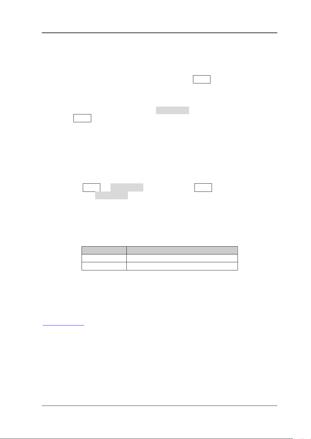
Format Conventions in this Manual
1. Button:
The key at the front panel is denoted by the following format: “Text Box +
Button Name (Bol d)” in the manual, for example, FREQ denotes the FREQ key.
2. Menu:
The menu is denoted by the following format: “Cha racter Sha ding + Menu Word
(Bold)” in the manual, f or e xample, Frequency denotes the frequency item
under FREQ.
3. Connector:
The connector at the front or rear panel is denoted by the following format:
“Square Brackets + Co nnector Name (Bold)” i n the manual, for example, [RF
OUTPUT 50Ω].
4. Operation Steps:
The next step of the operation is denoted by an arrow “” in the manual. For
example, FREQ Frequency denotes pressing FREQ on the front panel and
then pressing Frequency.
Content Conventions in this Manual
The DSG3000 series RF signal generat or includes the modes DSG3030 and DSG3060.
The illustrations in this manual are based on DSG3060.
Manuals of this Product
The manuals of this product include the quick guide, user’s guide, programming
guide and data sheet. The latest versions of the manuals can be downloaded from
www.rigol.com.
DSG3000 User’s Guide XI
Page 14

RIGOL
Contents
Guaranty and Declaration ......................................................................... I
Safety Requirement ................................................................................. II
General Safety Summary........................................................................... II
Safety Terms and Symbols ....................................................................... IV
Allgemeine Sicherheits Informationen ........................................................ V
Sicherheits Begriffe und Symbole ............................................................. VII
General Care and Cleaning ..................................................................... VIII
Environmental Considerations ................................................................. VIII
DSG3000 Series Overview ...................................................................... IX
Document Overview ................................................................................ X
Chapter 1 Quick Start ........................................................................ 1-1
General Inspection ................................................................................. 1-2
Appearance and Dim ensions ................................................................... 1-3
Front Panel Overview ............................................................................. 1-5
Rear Panel Overview ............................................................................ 1-12
To Use DSG3000 for the First Time ........................................................ 1-17
To Connect the Power Supply.......................................................... 1-17
Power-on Inspection ...................................................................... 1-18
To Set the System Language ........................................................... 1-18
To Replace the Fuse ............................................................................. 1-19
User Interface ...................................................................................... 1-20
Normal Disp l ay Mo de ..................................................................... 1-20
Parameter Zoom-in Mode ............................................................... 1-23
To Use the Built-in Help System ............................................................. 1-24
Chapter 2 Front Panel Operations ...................................................... 2-1
To Set the Frequency Parameters............................................................. 2-2
Frequency ....................................................................................... 2-2
Frequency Offset ............................................................................. 2-2
Phase Offset ................................................................................... 2-3
To Set the Amplitude Parameters ............................................................. 2-4
Amplitude ....................................................................................... 2-4
Amplitude Limit ............................................................................... 2-4
Amplitude Offset.............................................................................. 2-5
Attenuation Mode ............................................................................ 2-6
Attenuation ..................................................................................... 2-6
ALC ................................................................................................ 2-7
Hold Mode ...................................................................................... 2-7
Flatness Calibration .......................................................................... 2-7
Amplitude Unit ................................................................................ 2-9
Sweep................................................................................................. 2-10
XII DSG3000 User’s Guide
Page 15

RIGOL
Sweep Manner ............................................................................... 2-10
Sweep Direction ............................................................................. 2-10
Sweep Type ................................................................................... 2-11
Sweep Mode.................................................................................. 2-15
Single Sweep ................................................................................. 2-16
Reset Sweep ................................................................................. 2-16
Trigger Mod e ................................................................................. 2-16
Modulation .......................................................................................... 2-19
Amplitude Modulation (AM) ............................................................. 2-19
Frequency Modulation (FM)............................................................. 2-22
Φ
Phase Modulation (
M) .................................................................. 2-24
Pulse Modulation ........................................................................... 2-26
I/Q Modulation (Option IQ-DSG3000) .............................................. 2-34
LF Output ............................................................................................ 2-39
To Enable the LF Output ................................................................. 2-39
To Set the LF Parameters ................................................................ 2-39
Power Mete r (Option PMC-DSG3000) ...................................................... 2-44
To Enable the Power Meter ............................................................. 2-44
Zero Type ...................................................................................... 2-45
Zero ............................................................................................. 2-45
Frequency Mod e ............................................................................ 2-45
Frequency ..................................................................................... 2-45
Average Measurement .................................................................... 2-46
Preset ........................................................................................... 2-46
Limit Measurement ........................................................................ 2-46
Recorder ....................................................................................... 2-48
Relative Measurement .................................................................... 2-49
Statistics ....................................................................................... 2-49
Unit .............................................................................................. 2-50
System Informat i on ........................................................................ 2-50
RX1000 (Option) .................................................................................. 2-51
Store and Recall ................................................................................... 2-52
File Type ....................................................................................... 2-52
Save ............................................................................................. 2-54
Recall ........................................................................................... 2-57
Rename ........................................................................................ 2-57
Delete........................................................................................... 2-58
Copy ............................................................................................. 2-58
To Create a Directory ..................................................................... 2-58
Filename Prefix .............................................................................. 2-59
Disk Management .......................................................................... 2-59
System Update .............................................................................. 2-59
To Set the System Parameters ............................................................... 2-60
Language ...................................................................................... 2-60
Reset ............................................................................................ 2-60
I/O Configuration ........................................................................... 2-61
DSG3000 User’s Guide XIII
Page 16

RIGOL
Display Setting .............................................................................. 2-63
Power Status ................................................................................. 2-63
Information ................................................................................... 2-63
License ......................................................................................... 2-64
Self-test ........................................................................................ 2-65
Sanitation ..................................................................................... 2-65
Chapter 3 Remote Control ................................................................. 3-1
Remote Control Overview ....................................................................... 3-2
Control Via US B ..................................................................................... 3-3
Control Via LAN ...................................................................................... 3-5
Control Via GPIB .................................................................................... 3-8
Chapter 4 Application Examples ........................................................ 4-1
To Output RF Signal ............................................................................... 4-2
To Output RF Sweep Signal ..................................................................... 4-3
To Output RF Modulated Signal ............................................................... 4-5
Pulse Train Application ............................................................................ 4-6
Chapter 5 Troubleshooting ................................................................ 5-1
Chapter 6 Specifications .................................................................... 6-1
Specifications ........................................................................................ 6-2
Frequency ....................................................................................... 6-2
Level .............................................................................................. 6-4
Internal Modulation Generator (LF) ................................................... 6-5
Modulation
[1]
.................................................................................. 6-6
Inputs and Outputs ........................................................................ 6-10
General Specifications .......................................................................... 6-11
Chapter 7 Appendix ........................................................................... 7-1
Appendix A: DSG3000 Accessories and options ......................................... 7-1
Appendix B: Warranty ............................................................................. 7-2
Index ........................................................................................................ 1
XIV DSG3000 User’s Guide
Page 17

Chapter 1 Quick Start RIGOL
Chapter 1 Quick Start
This chapter guides users to quickly get familiar with the appearance, dimensions,
front panel, rear panel, and the use r interface of DS G3000 series RF signal generator.
The contents of this chapter are as follows:
General Inspection
Appearance and Dim ensions
Front Panel Overview
Rear Panel Overview
To Use DSG3000 for the First Time
To Replace the Fuse
User Interface
To Use the Built-in Help System
DSG3000 User’s Guide 1-1
Page 18

RIGOL Chapter 1 Quick Start
General Inspection
1. Inspect the shipping container for damage
Keep the damaged shipping container or cushioning material until the conten ts
of the shipment have been checked for completeness and the instrument has
passed both ele ctrica l and mechanical tests.
The consigner or carrier shall be liable for the damage to instrument resulting
from shipment. RIGOL is not responsible for free maintenance/rework or
replacement of the unit in such cases.
2. Inspect the instrument
In case of any damage, or defect, or failure, notify your RIGOL sales
representative immediately.
3. Check the accessories
Please check the accessories according to the packi ng li s ts . If the accessories
are incomplete or damaged, please co ntact your RIGOL sales representative
immediately.
1-2 DSG3000 User’s Guide
Page 19
Chapter 1 Quick Start RIGOL
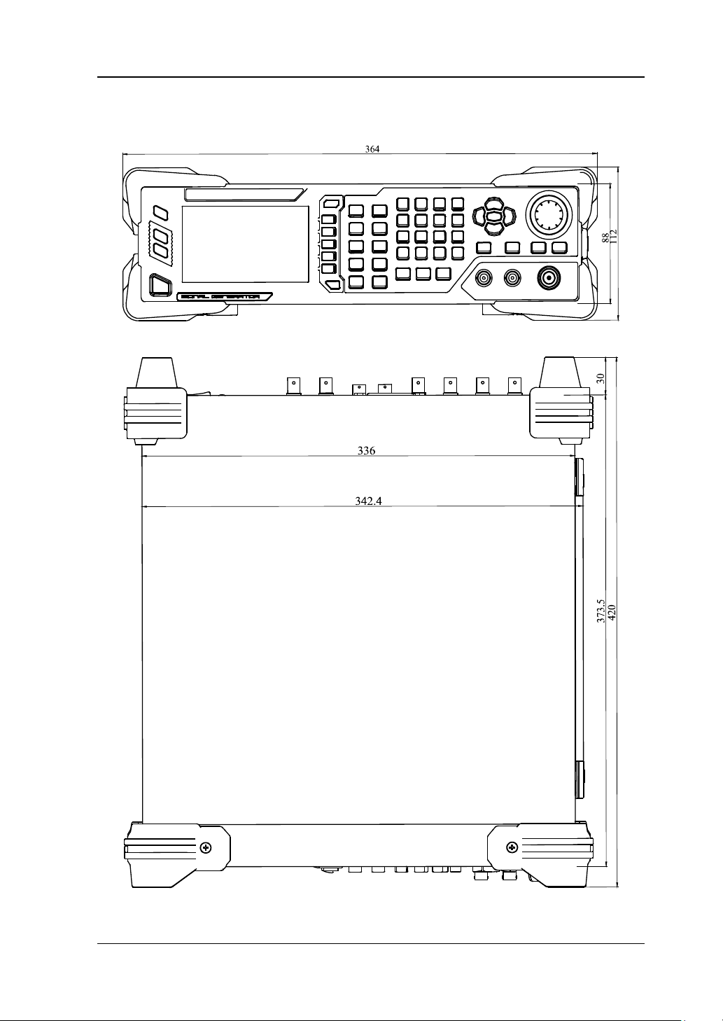
Appearance and Dimensions
Figure 1-1 Front View (unit: mm)
Figure 1-2 Top View (unit: mm)
DSG3000 User’s Guide 1-3
Page 20
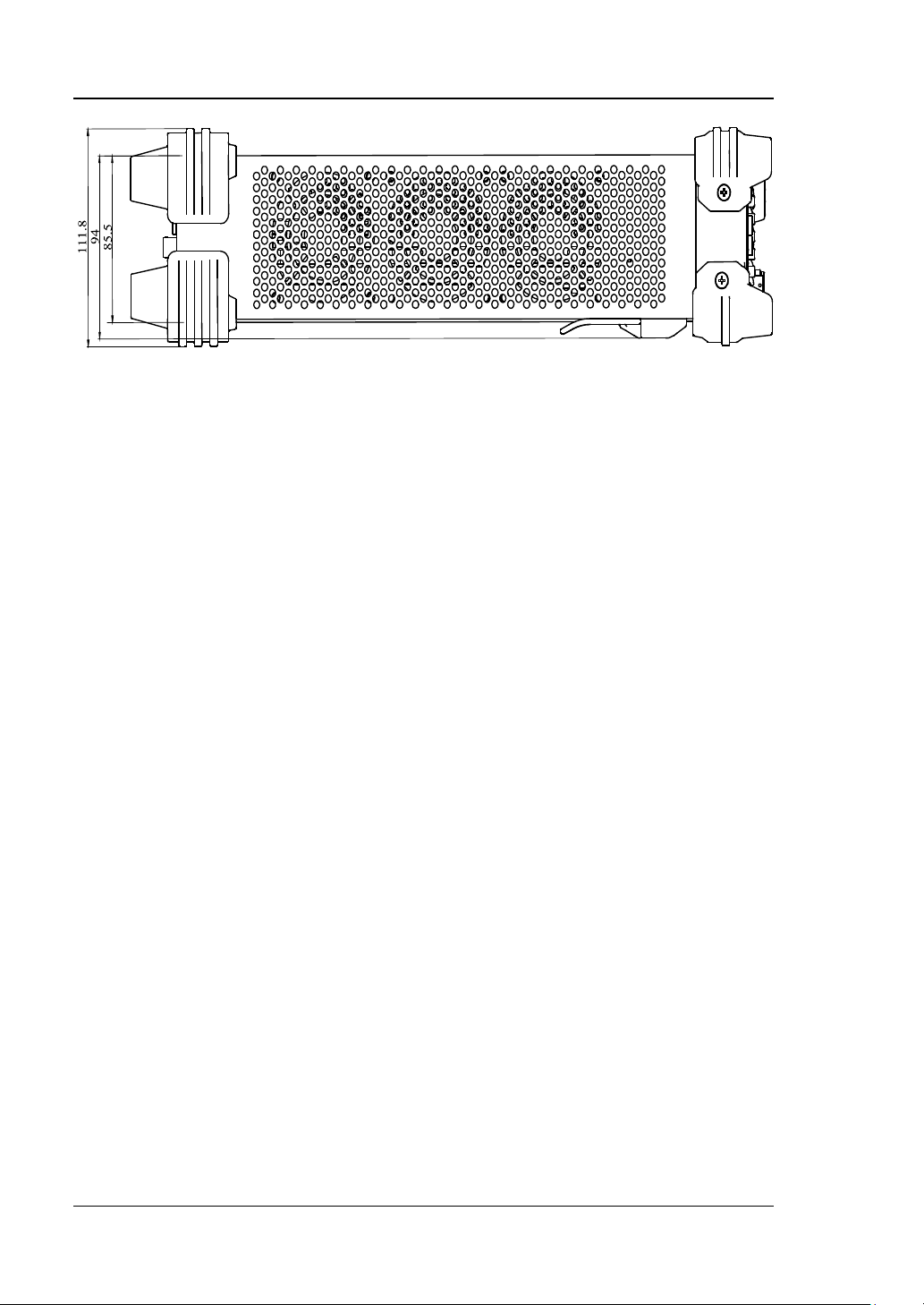
RIGOL Chapter 1 Quick Start
Figure 1-3 Lateral View (unit: mm)
1-4 DSG3000 User’s Guide
Page 21
Chapter 1 Quick Start RIGOL
Restore the instrument to the preset state (factory state or
4.3 inch TFT high-resolution (480×272) color LCD display.
Interface”.
Quit the current menu and return to the previous menu.
Menu softkey. Corresponds to the menu label at the left of
Menu page up/down key.
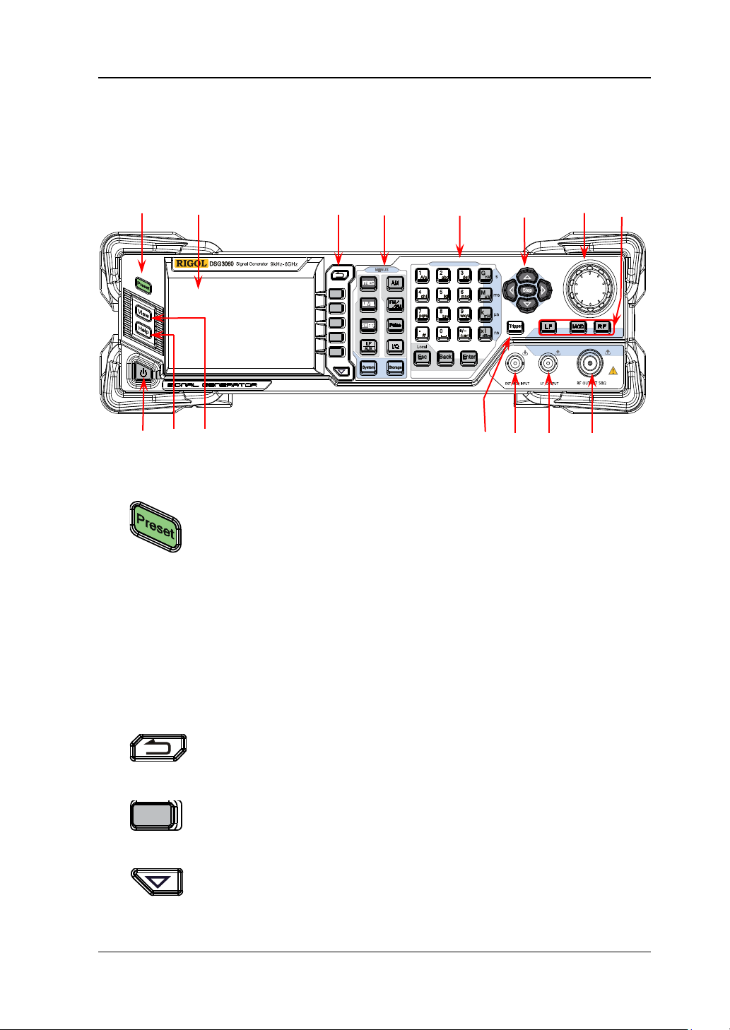
Front Panel Overview
The front panel of DSG3000 series RF signal generator is as shown in the figure
below. Click the number in the figure to view the corresponding introduction.
1 2 3 4 5 6 7 8
9 10 11 12 13 14 15
Figure 1-4 Front Panel
1. Restore to Preset Key
user-stored state).
2. LCD Display
The current settings and state of the instrument can be
clearly displayed. For detailed inf or mat ion , ref er to “
3. Menu Control Keys
the softkey on the display. Press the softkey to activate the
corresponding menu.
User
DSG3000 User’s Guide 1-5
Page 22
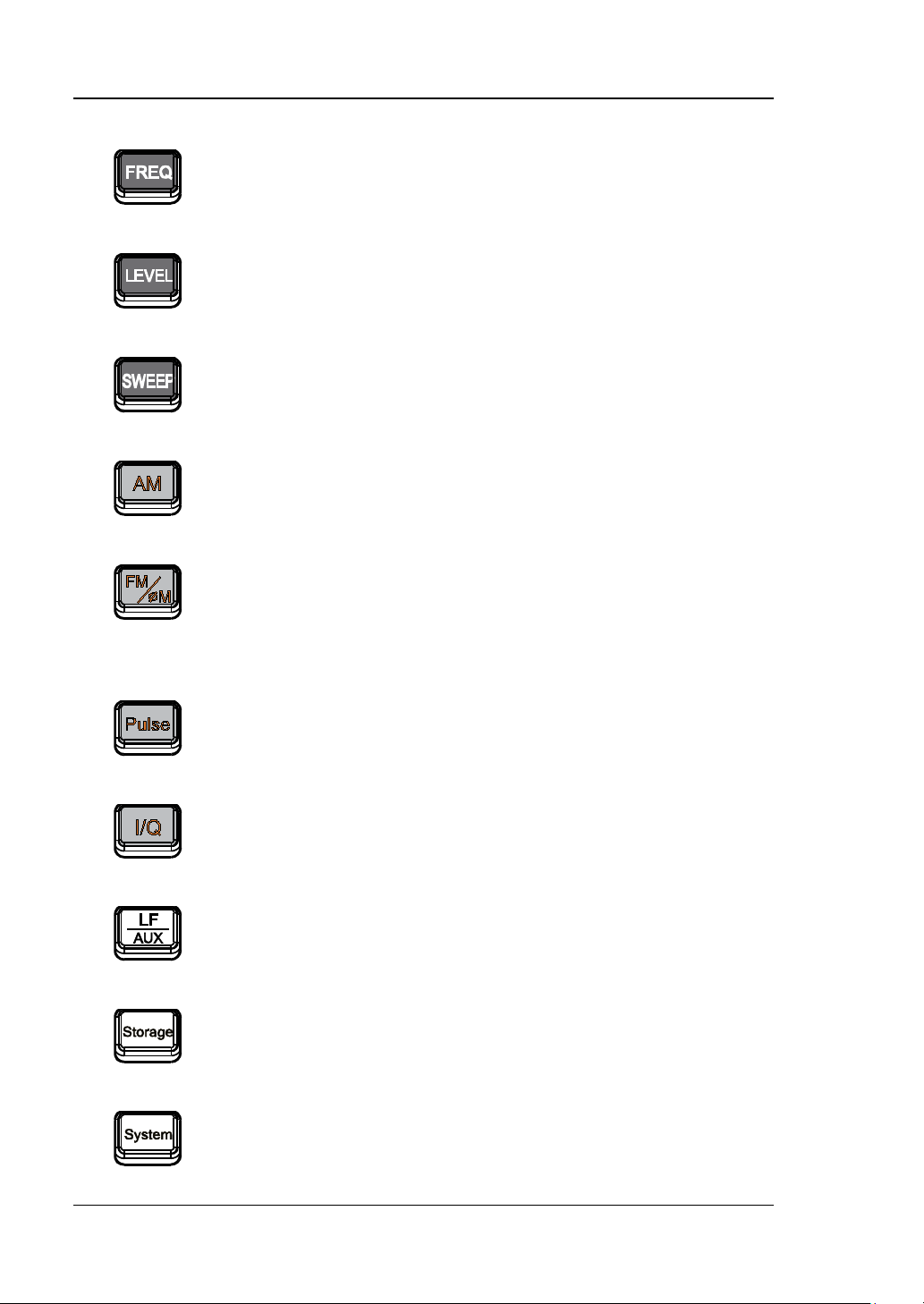
RIGOL Chapter 1 Quick Start
Set the frequency, frequency offset and phase offset of the
Set the amplitude and attenuation of the RF output signal
Set the sweep type, sweep manner and sweep mode. For
Set the parameters relating to amplitude modulation (AM).
Set the parameters relating to frequency modulation (FM)
Set the parameters relating to pulse modulation and pulse
Set the parameters relating to I/Q modulation and I/Q
Set the parameters relating to LF output and other extended
Store and recall the instrument state, flatness calibration
Set the system-related parameters. For details, refer to “To
4. Function Keys
Frequency Parameters”.
and provide the flatness calibration function. Fo r det ai ls,
RF output sign a l. For details, refer to “To Set the
refer to “
To Set the Am plitude Parameters”.
details, refe r to “Sweep”.
For details, refer to “Amplitude Mo d u l ation (AM)”.
and phase modulation (ΦM). For details, refer to
Frequency Modulation (FM)” and “Phase Modulation
“
(ΦM)
”.
generator. For detail s , refer to “Pulse Mod ulation”.
modulation source.
functions.
data, sweep list and so on. For details, refe r t o “Store and
Recall”.
Set the System Parameters”.
1-6 DSG3000 User’s Guide
Page 23
Chapter 1 Quick Start RIGOL
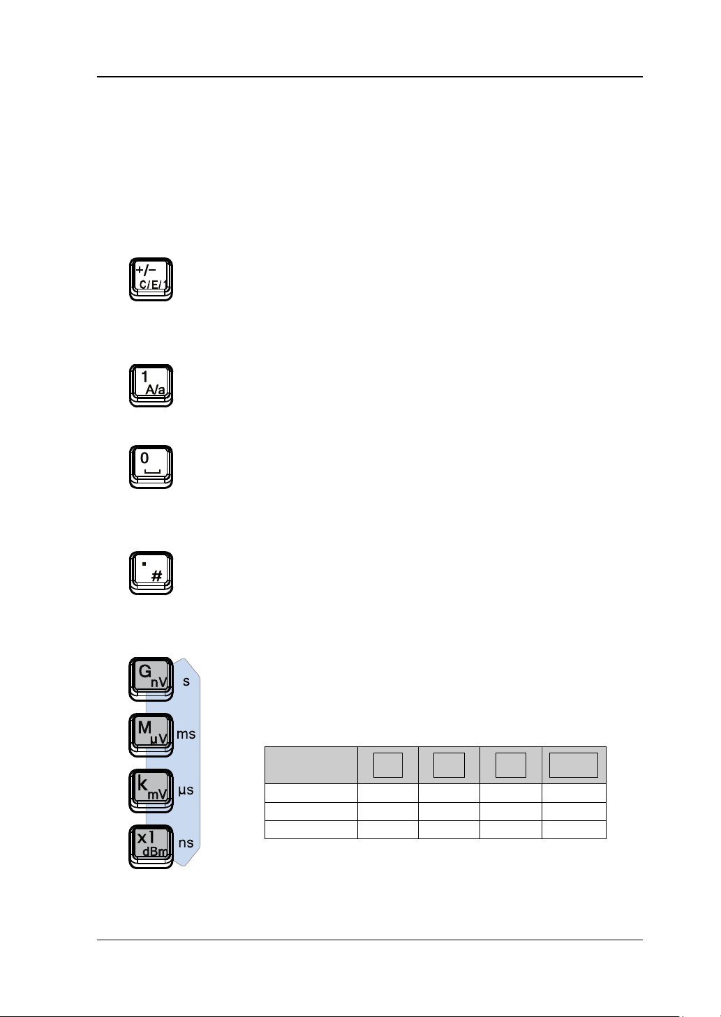
The numeric keyboard supports Chinese characters, English uppercase
The multiplexing key of number and letter is used to directly input the desired
Used to switch among Chi nese, En glish an d num ber i nput
In number input mode, press this key to input 1.
The multiplexing key of 0 and s pace:
In number input mode, press this key to insert a decimal
Used to set the unit of the parameter.
keyboard to input the numbers, press one of these keys to
Frequency
GHz
MHz
kHz
Hz
Amplitude
nV
μV
mV
dBm
Period
s
ms
μs
ns
5. Numeric Keyboard
/lowercas e ch aracters, numbers and commonly used symbols (include the
decimal point, #, space and p ositive/negativ e sig n+/-). It is mainly used to e dit
the fi le or folder name or set parameters.
number or letter.
When setting parameters, the input mode is fixed at
number and this key is used to input the sign (“+” or “-”)
of the value.
In English input mode, press this key to switch between
modes.
uppercase and l owercase letter input.
In number input mode, press this key to input 0.
In Chinese or English input mode, press this k ey to input a
space.
point at the current cursor.
In English input mode, press this key to input “#”.
In Chinese input mode, this key is invalid.
When setting a parameter, after using the numeric
select the corresponding unit. The unit sele cted is re lat ed
to the type of the parameter to be set.
Parameter
GnV MμV kmV X1
DSG3000 User’s Guide 1-7
dBm
Page 24
RIGOL Chapter 1 Quick Start
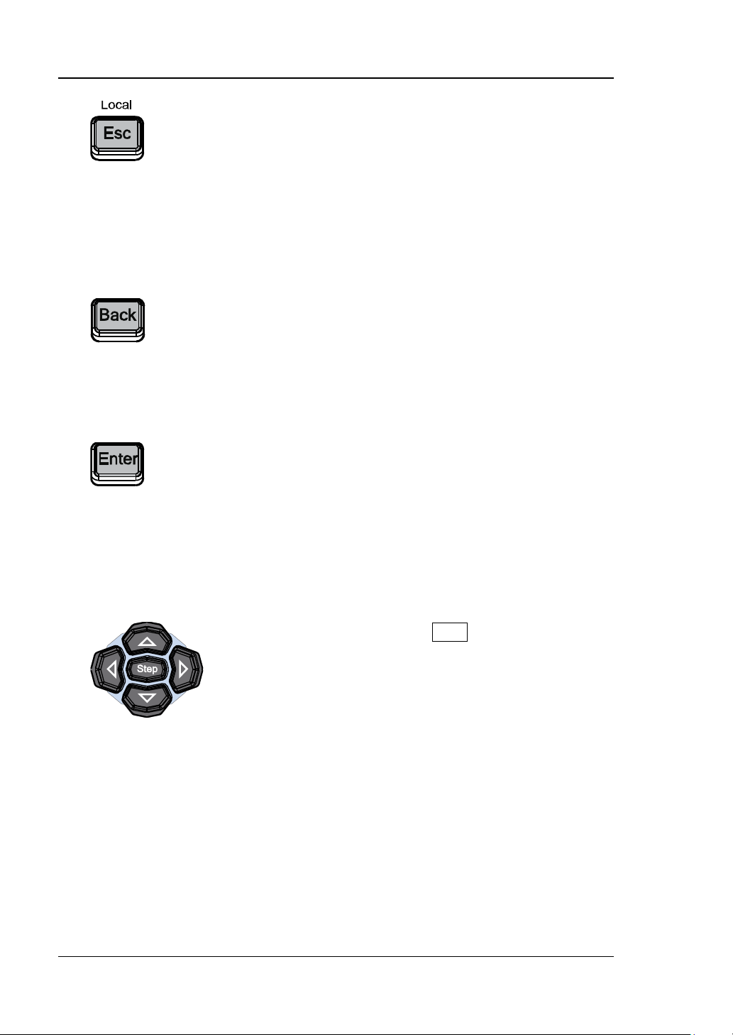
When setting parameters, use this key to clear the
When setting parameters, use this key to delete the
When setting parameters, use this key to finish the
currently selected.
When setting the parameters, Step is used to set the
number in the editing window and exit the parameter
input state.
When editing filenames, use this key to clear the
characters in the input bar.
During the keyboard test, use this key to exit the current
test state.
When the instrument is in remote mode, use this key to
return to local mode.
When editing filenames, use this key to delete the
character at the left of the cursor.
For the storage function, it is used to collapse the
directory currently selected.
parameter input and add the default unit for the
number at the left of the cursor.
parameter.
When editing filenames, use this key to input the
character currently selected by the cursor.
For the storage function, it is used to expand the directory
6. Direction Keys/Step Key
step of the parameter currently selected.
The left/right direction keys are used to enter the
parameter editing state and move the cursor to the
specified digit.
The up/down direction keys are used to modify the v alue
at the cursor or modify the pa rameter v alue at the current
step.
For the storage function, the left/right direction keys are
used to collapse or expand the director y currently
selected.
The up/down direction ke ys are use d to select the current
directory or f ile.
When editing filenames, they are used to select the
desired character.
1-8 DSG3000 User’s Guide
Page 25
Chapter 1 Quick Start RIGOL
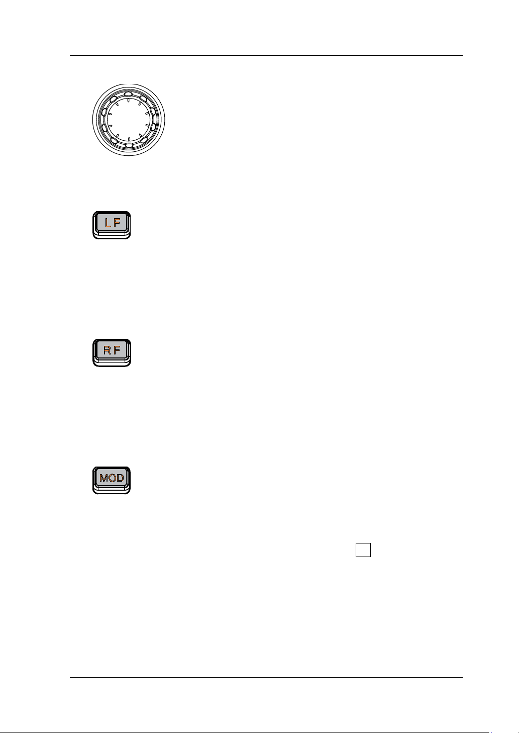
When setting parameters, the knob is used to modify
the value at the cursor or mo dify the par amet er v alu e at
directory or f ile.
Used to turn on or off the LF output.
Press this key, the backlight goes on and the LF label
Used to turn on or off the RF output.
Press this key, the backlight goes on and the RF l abel
Used to turn on or off the RF modulation output.
7. Knob
the current step.
When editing filenames, it is used to select the desired
character.
For the storage function, it is used to select the current
8. Output Contr ol Keys
—
is displayed in the status bar in the user interface.
The LF output is turned on. At this point, the [LF
OUTPUT] connector outputs the LF signal according
to the current configuration.
— Press this key again, the backlight goes out and the
LF output is turned off.
—
is displayed in the status bar in the user interface.
The RF output is turned on. At this point, the [RF
OUTPUT 50Ω] connector outputs RF signal or RF
sweep signal according to the current configuration.
— Press this key again, the backlight goes out and the
RF output is turned off.
— Press this key, the backlight goes on and the MOD
label is displayed in the status bar in the user
interface. The RF modulation output is turned on. At
this point, the [RF OUTPUT 50Ω] connector
outputs modulated RF sig nal acco rding to the current
configuration (the backlight of RF must go on).
— Press this key again, the backlight goes out and the
RF modulation output is turned off.
DSG3000 User’s Guide 1-9
Page 26
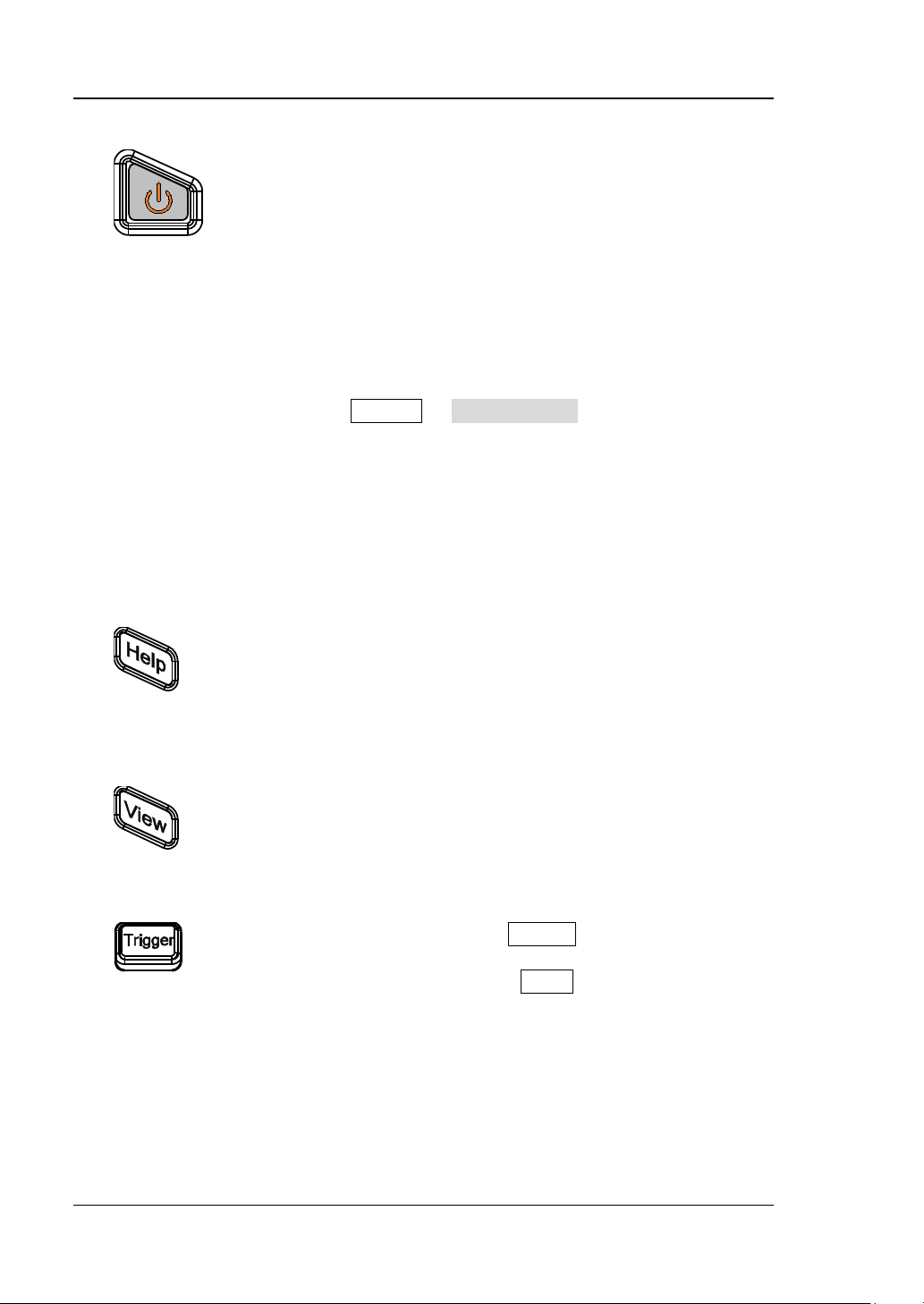
RIGOL Chapter 1 Quick Start
Turn on or off the signal generator. When this key is
To get the help information of any front panel key or
It is used to switc h t he int erf ace dis play mode to normal
refer to “User Interface”.
When the trigger type of SWEEP is “Key”, press this key
once to enable a pulse modulation.
9. Power Key
turned off, the signal generator is in standby state,
indicated by a pulsing LED. To fully remove power from
the instrument, flip the rear panel power switch off and
remove the power cor d. In addition, this key has a
delayed switching function. The instrument can be
turned on or off o nly when pressing this key and holding
it down for a certain time. With this feature, you can
avoid turning off the instrument because of accidentally
touching the key.
Press System Power Status to select “Open” or
“Default”. When ”Default” is selected, after the
instrument is powered on and the power switch at the
rear panel is turned on, you need to press this key to
start the instrument. When ”Open” is selected, the
instrument will start automatically aft er it is powered on
and the power switch at the rear panel is turned on.
10. Built-in Help Sys te m
menu softkey, press this key and then press the desired
key.
11. View Switch Key
mode or parameter zoom-in mode. For details, please
12. Trigger Control Key
once to trigger a sweep.
When the trigger mode of Pulse is “Key”, press this key
1-10 DSG3000 User’s Guide
Page 27
Chapter 1 Quick Start RIGOL
When the modulation source of AM, FM and ΦM is
When the backlight of LF goes on, this connector is
When the backlight of RF goes on, this connector is
CAUTION
MHz to 6 GHz.
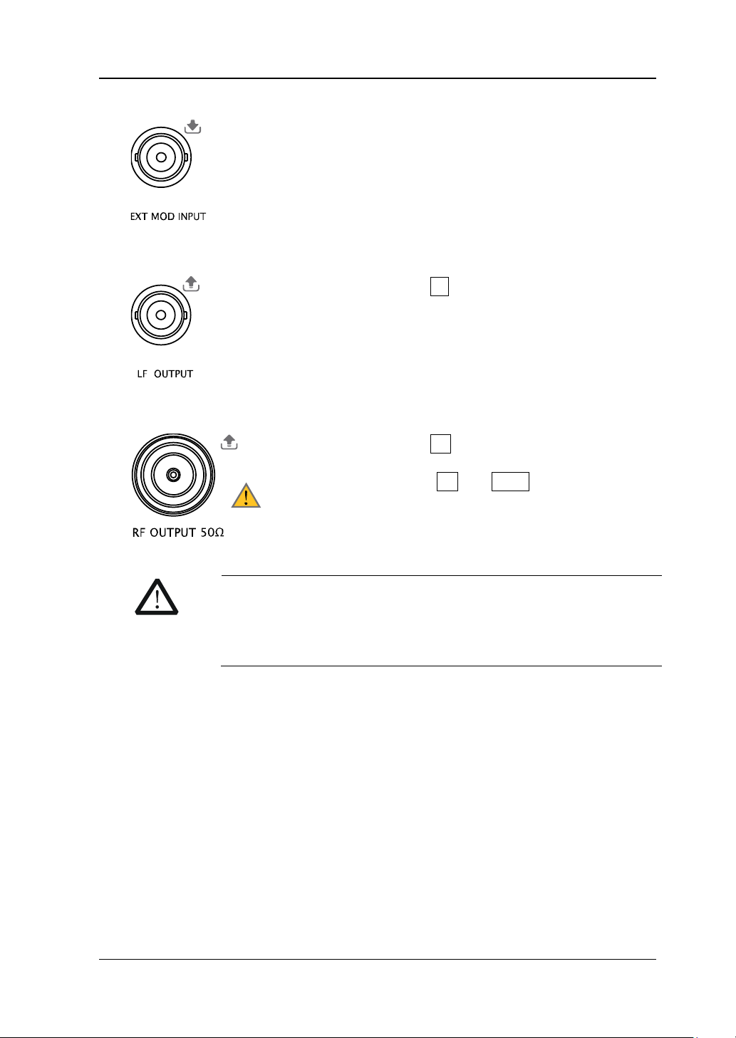
13. External Modulation Input Connector
external, this connector is used to input the external
modulating signal.
14. LF Output Connector
used to output LF signal.
15. RF Output Connector
used to output RF signal and RF sweep signal.
When the backlights of RF and MOD go on, this
connector is used to output RF modulated signal.
To avoid damage to the instrument, the reverse DC voltage on
the RF output connector cannot exceed 50 V, the rev erse power
must be less than +40 dBm (10W) in frequency r ange from 1
DSG3000 User’s Guide 1-11
Page 28
RIGOL Chapter 1 Quick Start
The instrument complies with USBTMC class
This input is used to connect the USB storage device
calibration of a measurement system.
The instrument complies with LXI core device 2011
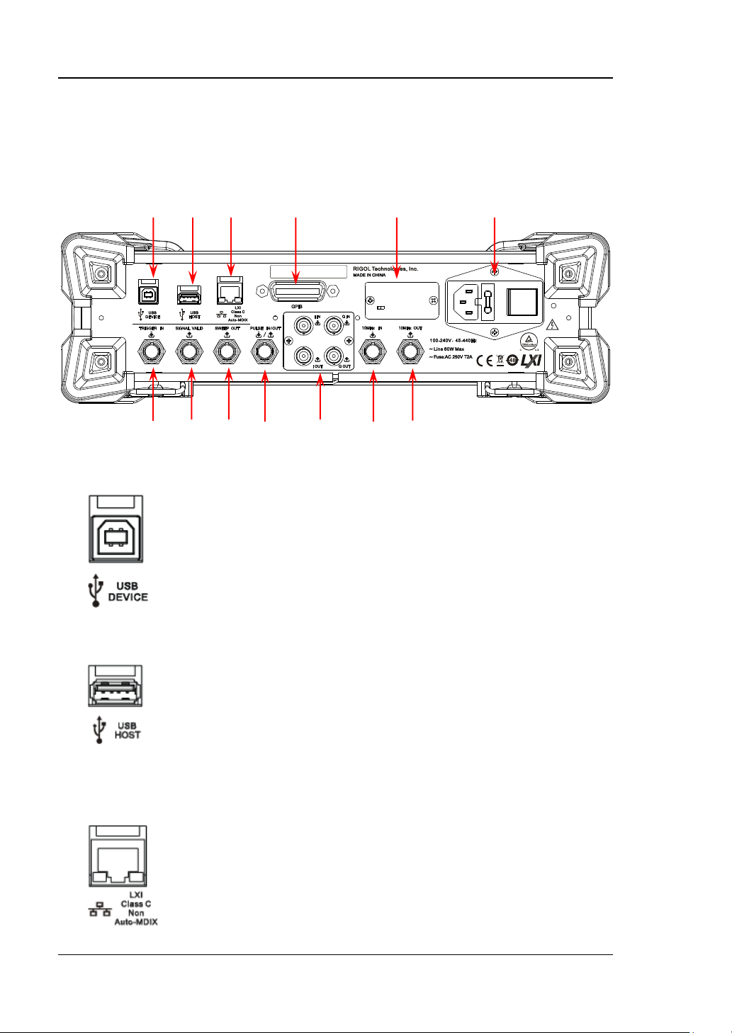
Rear Panel Overview
The rear panel of DSG3000 series RF signal generator is as sh own in the figure below.
Click the number in the figure to view the corresponding introduction.
1 2 3 4 5 6
7 8 9 10 11 12 13
Figure 1-5 Rear Panel
1. USB Device
protocol.
This interface is used to connect to a PC for remote
instrument control.
2. USB Host
to update the system, store system states and
sweep lists. You can also connect the USB power
sensor or power meter with USB interface to achiev e
power measurement control and amplitude
3. LAN
class standard, and supports WebServer, Socket and
other remote control modes.
This interface is used to connect the PC or netwo rk
for remote instrument control.
1-12 DSG3000 User’s Guide
Page 29
Chapter 1 Quick Start RIGOL
The instrument complies with the IEEE488.2
enable remote instrument control.
OCXO is an oven controlle d crystal os cillator. It
refer to the
data sheet
.
Power input connector.
Fuse.
Power Switch
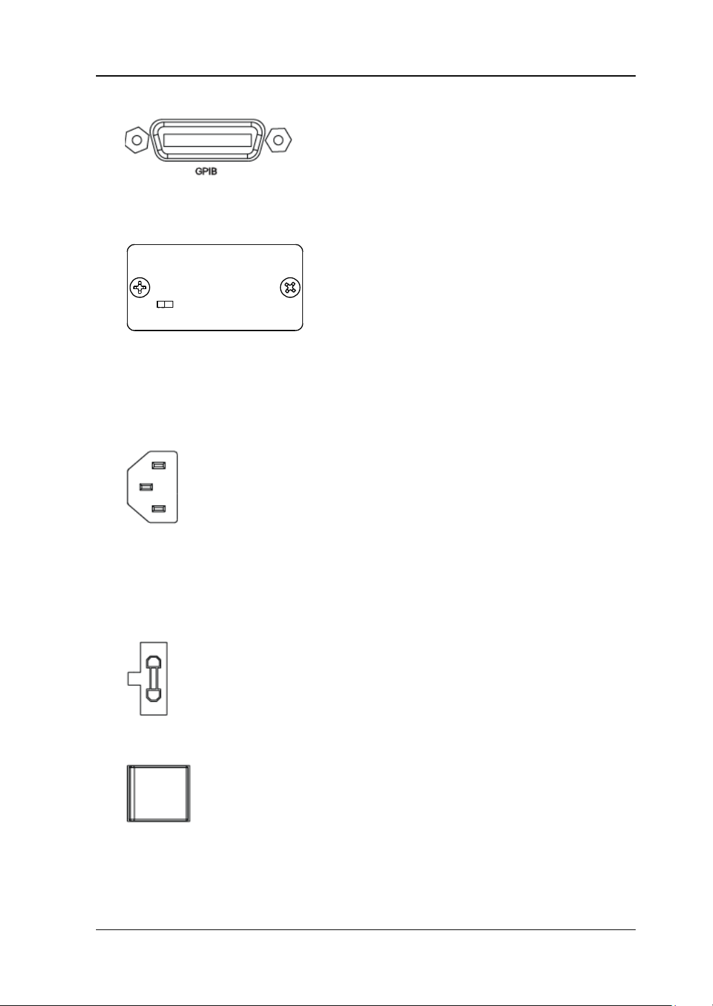
4. GPIB
standard.
This interface is used to connect the PC to
5. OCXO (option OCXO-A08)
is a frequency reference source with higher
temperature stability.
NOTE: Forty minutes of warm-up is required
for the OCXO to reach its rated frequency.
For ordering information of this opt i on, please
6. Power Input Connector, Fuse and Switch
The AC power supply specific ation of this
signal generator is 100-24 0 V, 45-440 Hz. The
power consumption of the instrument cannot
exceed 60 W. When the signal generator is
connected to AC power supply via this
connector, the instrument selects the correct
voltage range automatically and users do not
need to select the voltage range manually.
The fuse specification of this signal generator
is AC 250 V, T2A.
If the fuse needs to be replaced, please refer
to “To Replace the Fuse
”.
It is used to turn on or off the signal generator.
DSG3000 User’s Guide 1-13
Page 30
RIGOL Chapter 1 Quick Start
When the trigger type of SWEEP o r “ Sw p-Sine”
When the RF output frequency or amplitude is
is stable (namely, the signal is valid).
3.3V
0V
Power-on Time
RF Valid
Configuration
Time
Configuration
Time
RF Valid
… …
V
T
When the RF sweep function is enabled, the
this output signal is ramp.
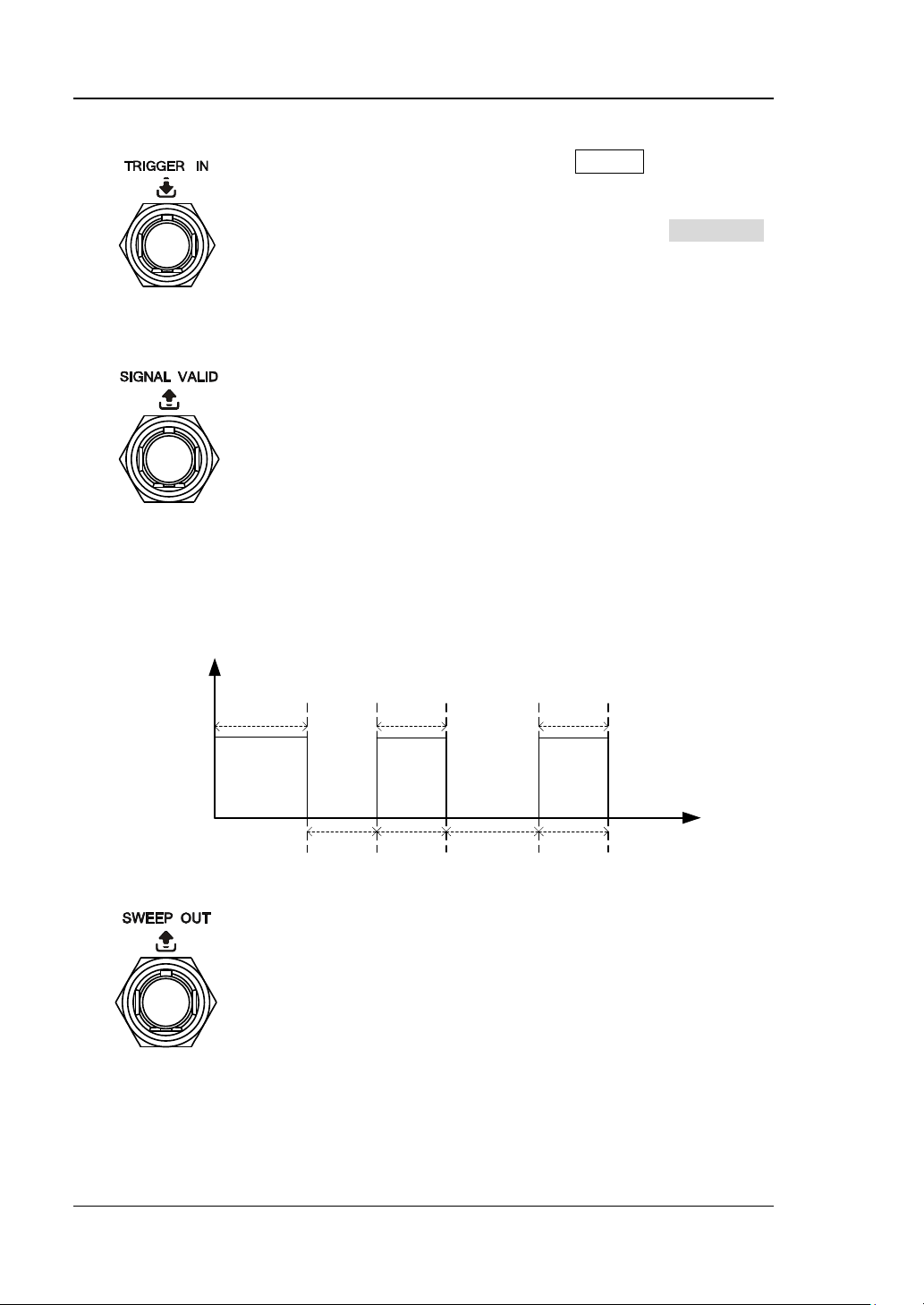
7. External Trigger Input Connector
of LF output is “Ext”, this connector is used to
input the external trigger signal. You can set the
polarity of trigger signal by pressing Trig Slope
to select “Pos” or “Neg”
8. Signal Valid Output Connector
modified, after a certain response and processing
time, the internal circuit of the instrument
outputs RF signal with specified frequency and
amplitude via the RF output connector at the
front panel. During this process, the [SIGNAL
VALID] connector outputs a pulse sync signal,
indicating that the RF output signal is valid.
— High Level (+3.3 V): indicates that the RF
signal is in configuration;
— Low Level (0 V): indicates that the RF signal
9. Sweep Output Connector
[SWEEP OUT] connector outputs a signal (0 V
to +10 V) while the RF output connector at the
front panel outputs the swe ep signal a ccordin g to
the current setting. Each sweep corresponds to
1-14 DSG3000 User’s Guide
an output cycle.
— When the sweep type is step, this output
— When the sweep type is list, the default of
signal is related to t he choice of sweep shape
which can be set to “Triangle” or “Ramp”.
Page 31

Chapter 1 Quick Start RIGOL
The function of this connector is determined by the
internal and the trigger mode is “Ext Gate”, this
or “Train”.
When I/Q modulation typ e is “ external”, it is used to
When I/Q modulation typ e is “ external”, it is used to
It is used to output the I (In-Phase) components of
It is used to output the Q (Quadrature Phase)
10. Pulse Signal Input/Output Connector
current working mode of the pulse modulation.
PULSE IN:
— When the modulation source of Pulse is
external, this connector is used to input the
external pulse signal.
— When the modulation source of Pulse is
internal and the trigger mode is “Ext Trig”, this
connector is used to input the external trig ger
signal.
— When the modulation source of Pulse is
connector is used to input the external gated
signal.
PULSE OUT:
When the modulation source of Pulse is internal
and the s witch of pulse ou tput is “on”, this c onnector
is used to output the pulse signal of the internal
generator. This output signal is related t o the choice
of pulse mode which can be set to “Single” , “Double”
11. I/Q Modulating Signal In/Out Connectors (option IQ-DSG3000)
input the I (In-Phase) baseband signal of I/Q
modulation.
input the Q (Quadrature Phase ) modulat ing signal of
I/Q modulation.
the I/Q modulation of the built-in baseband
generator.
components of the I/Q modulation of the built-in
baseband generator.
DSG3000 User’s Guide 1-15
Page 32

RIGOL Chapter 1 Quick Start
It is used to input the external 10 MHz reference
It is used to output the internal 10 MHz reference
12. Reference Signal Input Connector
clock signal which is used to synchronize the
generator with other instruments. For more
information about the external clock signal
specif ication of this connector, please refer to the
data sheet
.
13. Reference Signal Output Connector
clock signal used to synchronize the generator with
other instruments. For more inform a t i on about the
output clock signal specification of this connector,
please refer to the
data sheet
.
1-16 DSG3000 User’s Guide
Page 33

Chapter 1 Quick Start RIGOL
CAUTION
grounded.
To Use DSG3000 for the First Time
To Connect the Power Supply
Please connect the signal generator to AC power supply using the power cord
supplied in the accessories as shown in the figure below. The AC power supplies
specif ication of this signal generator is 100-240 V, 45-440 Hz. The power
consumption of the instrument cannot exceed 60 W. When the signal generator is
connected to AC power supply via this connector, the instrument select the correct
voltage range automatically and users do not need to select the voltage range
manually.
Figure 1-6 To Connect the Power Supply
To avoid electric shock, make sure that the instrument is correctly
DSG3000 User’s Guide 1-17
Page 34

RIGOL Chapter 1 Quick Start
Power-on Inspection
After the power supply is correctly connected, press the power switch at the rear
panel and the power key
During the start-up, the instrument performs initialization and self-test. After that,
the instrument enters the default interface.
at the front panel to turn on the signal generator.
To Set the System Language
DSG3000 series RF signal generator supports multiple system languages. You can
press System Language to switch the system language.
1-18 DSG3000 User’s Guide
Page 35

Chapter 1 Quick Start RIGOL
WARNING
before replacing the fuse.
The location of the
Fuse
Fuse Seat
To Replace the Fuse
To replace the fuse, please use the specified fuse and follow the steps below.
1. Turn off the instru ment, switch off the power su pply and remove the power cord
2. Use a small straight screwdriver to pry out the fuse seat
3. Take out the fuse seat
4. Replace the old fuse with a specified fuse
5. Re-install the fuse seat
fuse seat
Figure 1-7 To Replace the Fuse
To avoid electric shock, make sure that the instrume nt is turned of f , the
power supply is disconnected and the fuse used is up to sta ndard
DSG3000 User’s Guide 1-19
Page 36

RIGOL Chapter 1 Quick Start
User Interface
The user interface of DSG3000 series RF signal generator provides two display
modes: normal display mode and parameter zoom-in mode. At pow er -on, the
instrument enters the normal display mode by default. In this manual, the normal
display mode of DSG3060 is taken as an example to illustrate the user interface of
the instrument.
Normal Display Mode
1 2 3 4
5 6 7
Figure 1-8 User Interface (Normal Display Mode)
1. Frequency Area
Display the current frequency setting of the RF signal generator.
—
—
: Displayed when the frequency offset is not 0 Hz.
: Continuous sweep label. Displayed w hen the sweep type is “Freq” or
“Freq&Lev” and the sweep mode is “Cont”.
—
: Single sweep label. Displayed when the sweep type is “Freq” or
“Freq&Lev” and the sweep mode is “Single”.
—
: Fo rward sweep labe l. Displayed when the sweep type is “Freq” or
“Freq&Lev” and the sweep direction is “Fwd”.
—
: Down sweep label. Displayed when the sweep type is “Freq” or
“Freq&Lev” and the sweep direction is “Down”.
—
: Frequency sweep progress bar. Displayed when the
sweep type is “Freq” or “Freq&Lev”.
1-20 DSG3000 User’s Guide
Page 37

Chapter 1 Quick Start RIGOL
2. Status Bar
Indicate the states of some of the RF signal generator functions.
—
: Displayed when the LF output is enabled. This is grayed out when
the LF output is disabled.
—
: Displayed when the RF modulation output is enabled. This is
grayed out when the RF modulation output is disabled.
—
: Displayed when the RF output is enabled. This is grayed out when
the RF output is disabled.
—
—
: The RF signal generator is operating in remote control mode.
: The RF signal generator is operating in local mode.
3. Amplitude Area
Display the current level setting of the RF signal generator.
—
—
—
—
—
—
: Displayed when the attenuation mode is “Fixed”.
: Displayed when the ALC state is “On”.
: Displayed when the ALC state is “Auto”.
: Displayed when the flatness calibration switch is “On”.
: Displayed when the amplitude offset is not 0 dB.
: Continuous sweep la bel. Displaye d when the s weep type is “Level” or
“Freq&Lev” and the sweep mode is “Cont”.
—
: Single sweep label. Displayed when the sweep type is “Level” or
“Freq&Lev” and the sweep mode is “Single”.
—
: Fo rward sweep labe l. Disp layed when the sweep type is “Level” or
“Freq&Lev” and the sweep direction is “Fwd”.
—
: Down sweep label. Displayed when the sweep type is “Level” or
“Freq&Lev” and the sweep direction is “Down”.
—
: Amplitude sweep progress bar. Displayed when the
sweep type is “Level” or “Freq&Lev”.
4. Menu Display Area
The menus in this area correspond to the softkeys at the right of the screen.
Pressing any sof t ke y can enable the corresponding menu function.
5. Message Display Area
Display the operation error messages and prompt messages. You can press
System Information System Msg to view the messages. When
multiple messages are generated, you can use the up/down direction keys or
knob to select the message row to be vi ewed. When the messages cannot be
displayed completely in the list, press Verbose to view the complete
information of the current row selected in the message list.
6. Function Status Area
Display the current active states of each function. Each function corresponds to
at most four kinds of states as shown in the table below.
DSG3000 User’s Guide 1-21
Page 38

RIGOL Chapter 1 Quick Start
Type
Explanation
Example
Gray text on a
black background
The function is not selected and enabled.
Black text on a
gray background
The function is selected and you can set
the correspon di ng parameters.
White text on a
gray background
The function is selected and enabled.
White text on a
black background
The function is not selected but it is
enabled.
The frequency parameters
can be set .
The level parameters
can be set .
The sweep parameters can be set .
Enable any type of “Freq”, ”Level”
or “Freq &Level” to sweep.
The LF output, power meter
(option), RX1000 (option)
parameters can be set.
Select LF as the currently active
function, and turn on the LF switch.
Select other operations (except LF)
as the currently active function,
and turn on the LF switch.
The AM parameters can
be set.
Select and turn on the
AM switch.
Select other operations
(except AM) as the
currently active function,
and turn on the AM switch.
The FM parameters can be set.
Select and turn on the FM switch.
Select other operations (except
PM) as the currently active
function, and turn on the PM
switch.
The PM parameters can be set.
Select and turn on the PM switch.
Select other operations (except
SWEEP) as the currently active
function, and enable the sweep.
The pulse modulation parameters
can be set.
Select and turn on the
pulse modulation switch.
Select other operations (except
Pulse) as the currently active
function, and turn on the pulse
modulation switch.
The I/Q modulation parameters
can be set.
Select and turn on the I/Q
modulation switch.
The system parameters
can be set .
Select other operations (except I/Q)
as the currently active function, and
turn on the I/Q modulation switch.
The AM function is not
selected and enabled.
The sweep function is not
selected and enabled.
The LF output is not
selected and enabled.
The PM function is not
selected and enabled.
The pulse modulation function
is not selected and enabled.
The I/Q modulation function is
not selected and enabled.
The system parameters
setting is not selected.
The frequency parameters
setting is not selected.
The status labels in the function status area as shown in the figure below.
Figure 1-9 Labels in Function Status Area
7. Text Display Area
Display the corresponding parameter information of the current function of the
RF signal generator.
1-22 DSG3000 User’s Guide
Page 39

Chapter 1 Quick Start RIGOL
Parameter Zoom-in Mode
In normal display mode, pressing the display switch key View at the left of the
screen can switch to the parameter zoom-in mode as shown in the f ig ure below.
Figure 1-10 User Interface (Parameter Zoom-in Mode)
DSG3000 User’s Guide 1-23
Page 40

RIGOL Chapter 1 Quick Start
To Use the Built-in Help System
The DSG3000 built-in help system p rovides hel p inf o rmation f or all the fu nction keys
and menu softkeys located on the front panel. Users can view the help of any key
when operating the instrument.
1. Acquire the built-in h elp
Press Help and the prompt message about ho w t o a cquire the help inf or mation
is displayed in the test displa y area of the user interf ace, as shown in Figure 1-11.
Then, press the desired key and the help information of that key is displayed in
the text display area.
Figure 1-11 Help Interface
2. Page up/down
When the help information is displayed on multiple pages, users can a cquire th e
help information on the previous or next page using the direction keys or knob.
3. Turn off the current help information
When the help information is display ed in the te xt display area, pressin g any k ey
(except the direction keys and knob) at the front panel will turn off the help
information currently display ed.
4. Acquire the help information of a menu softkey
Press Help and help information is displayed in the text display area. Then,
press the desired menu softkey, the help information of the menu item
corresponding to this menu softkey is displayed in the text display area.
5. Acquire the help information of any function key
Press Help and help information is displayed in the text display area. Then,
press any function k ey a nd the f u nction hel p inf orm ation of t his ke y is displayed
in the text display area.
1-24 DSG3000 User’s Guide
Page 41

Chapter 2 Front Panel Operations RIGOL
Chapter 2 Front Panel Operations
This chapter introduces each function key at the front panel as well as the menu
functions under it in details.
The contents of this chapter are as follows:
To Set the Frequency Parameters
To Set the Amplitude Parameters
Sweep
Modulation
LF Output
Store and Recall
To Set the System Parameters
DSG3000 User’s Guide 2-1
Page 42

RIGOL Chapter 2 Front Panel Operations
To Set the Frequency Parameters
Frequency
Set the RF output frequency.
Press FREQ Frequency, use the numeric keyboard to input the value of the
frequency and select the desired unit from the pop-up unit menu or unit keys.
The frequency units available are GHz, MHz, kHz and Hz.
Press Enter to select the default unit (Hz).
You can also press the left/right direction keys to enter the parameter editing
state and move the cursor to the specified digit; and then use the up/down
direction key s or kn ob to modify the value.
After the frequency is set, you can use the up/down direction keys or knob to
modify the frequency at the current step.
Press FREQ Frequency and then press Step to set the step.
Frequency Offse t
Set the frequency offset relative to the RF output fr equen cy.
When using an external mixer and other devices, you can set and read the frequency
value through the ex t ernal mixer on the RF source by setting the frequency offset.
Press FREQ Offset, use the nu meric keyboard to input the value of the frequency
offset and select the desired unit from the pop-up unit menu or unit keys.
The frequency offset units available are GHz, MHz, kHz and Hz.
Press Enter to select the default unit (Hz).
You can also press the left/right direction keys to enter the parameter editing
state and move the cursor to the specified digit; and then use the up/down
direction key s or kn ob to modify the value.
You can also use the up/down direction keys or knob to modify the frequency
offset at the current step.
Press FREQ Offset and then press Step to set the step.
2-2 DSG3000 User’s Guide
Page 43

Explanation
instrument.
Chapter 2 Front Panel Operations RIGOL
1. When the freq uency offset is 0 H z, the frequency displayed in the interface
(namely setting frequency) is equal to the actual output frequency.
2. When frequency offset is not 0 Hz, the output frequency is determined by
setting frequency and frequency offset. The three parameters satisfy the
equation: setting frequency (display frequency) = output frequency +
frequency offset
3. The deviation (namely the actual output frequen cy) between i nterfa ce display
frequency and frequency offset cannot exceed the frequency range of
Phase Offset
Set the phase offset of t he RF signal.
When multiple RF signal gene r ators ar e used to output signals, you can adjust the
phase offset of the instrumen t to synchronize the phase or set a fixed phase offset
for the signals.
Press FREQ Phase Offset, after that use the numeric keyboard to input the
value of the phase offset and press deg or the unit key.
Press Enter to select the default unit (deg).
Press the left/right direction keys to enter the parameter editing state.
You can als o use the u p/down direction k e ys or knob to m odif y the phase offset
at the current step.
Press FREQ Phase Offset and then press Step to set the step.
Press Rst Phase to reset the current phase offset to 0 deg.
DSG3000 User’s Guide 2-3
Page 44

RIGOL Chapter 2 Front Panel Operations
To Set the Amplitude Parameters
Amplitude
Set the RF output amplitude.
Press LEVEL Level, use the numeric keyboard to input the amplitude value and
select the desired unit from the pop-up unit menu or unit keys.
The amplitude units available are dBm, -dBm, mV, μV and nV.
Press Enter to select the default unit (dBm).
You can also press the left/right direction keys to enter the parameter editing
state and move the cursor to th e sp e cified digit and then use the up/down
direction key s or kn ob to modify the value.
You ca n also use the up/down direction ke ys or kno b to modify the amplitude at
the current step.
Press LEVEL Level and then press Step to set the step.
Amplitude Li mit
Set the limit of the RF output am plitude. This value is the upper limit of the RF output
amplitude.
To limit the output amplitude, you can use the amplitude limit function to avoid
damage caused by delivering a high powere d signal to the external circuit.
Press LEVEL Limit, us e the numeri c keyboard to input t he value of the amplitude
limit and select the desired unit from the pop-up unit menu or unit keys.
The amplitude limit units available are dBm, -dBm, mV, μV and nV.
Press Enter to select the default unit (dBm).
You can also press the left/right direction keys to enter the parameter editing
state and move the cursor to the specified digit; and then use the up/down
direction key s or kn ob to modify the value.
You can also use the up/down direction keys or knob to modify the amplitude
limit at the current step.
Press LEVEL Limit and then press Step to set the step.
2-4 DSG3000 User’s Guide
Page 45

Chapter 2 Front Panel Operations RIGOL
Explanation
) between interface display
attenuation mode, attenuation value and RF output frequency.
Amplitude Offset
Set the amplitude offset relative to the RF output amplitude.
If the external device or cir cuit has a fixed attenuation or gai n, y ou can s et an d re ad
the amplitude value after through the external device or circuit on the RF source by
setting the amplitude offset.
Press LEVEL Offset, use the numeric keyboard to input the amplitude offset
value and press dB or the unit key.
The amplitude offset unit av aila ble is dB.
Press Enter to select the default unit (dB).
You can also press the left/right direction keys to enter the parameter editing
state and move the cursor to the specified digit and then use the up/down
direction key s or kn ob to modify the value.
You can also use the up/down direction keys or knob to modify the amplitude
offset at the current step.
Press LEVEL Offset and then press Step to set the step.
1. When amplitude offset is 0 Hz, the amplitude displayed in the interface
(namely setting amplitude) is equal to the actual output amplitude.
2. When amplitude offset is not 0 Hz, output amplitude is determined by setting
amplitude and amplitude offset. The three parameters satisfy the equation:
setting amplitude (display amplitude) = output amplitude + amplitude offset
3. The deviation (namely the actual output amplitude
amplitude and amplitude offset cannot exceed the amplitude range of
instrument.
4. The current amplitude range of instrument is determined by amplitude limit,
DSG3000 User’s Guide 2-5
Page 46

RIGOL Chapter 2 Front Panel Operations
Explanation
output range.
Attenuation M ode
Set the attenuation mode of RF output.
If you want to get a larger amplitude setting range, you can set the attenuation
mode to auto. If you wa nt to get higher amplitude accuracy in a smaller amplitude
range, you can set the attenuation mode to fix ed.
Press LEVEL Atten Mode to set the attenuation mode of the RF output
amplitude to “Auto” or “Fixed”.
Auto: the default mode. In this mode, the attenuator adjusts the attenuation
automatically to match the c urrent amplitude setting. The refore, y ou can set t he
amplitude within the whole range.
Fixed: in this mode, the attenuation is the value set in Atten. Therefore, you
can only set the amplitude within a certain range. At this point, if the ALC is
enabled, you can set the amplitude within a certain range continuously. Please
refer to “
user interface.
Specifications”. The AH label is displayed in the amplitude area in th e
When the attenuation mode of the RF output amplitude is auto, the internal
attenuator p ro vi des at ten uation f or the output ampl itude to get a la rger dyna mic
Attenuation
Set the attenuation of the RF output amplitude in fixed attenuation mode.
Press LEVEL Atten Mode to select “Fixed”; press Atten, use the numeric
keyboard to input the amplitude attenuation value and press dB or the unit key.
The amplitude attenuation unit available is dB.
Press Enter to select the default unit (dB).
You can also press the left/r igh t direction keys to enter the parameter editing
state and move the cursor to the specified digit and then use the up/down
direction key s or kn ob to modify the value.
You can also use the up/down direction keys or knob to modify the amplitude
offset at the current step.
Press Step to set the step.
2-6 DSG3000 User’s Guide
Page 47

Chapter 2 Front Panel Operations RIGOL
ALC
Set the working state of the ALC function.
ALC is the automatic level control function. This f unc tion compa res the a ctual o utput
amplitude with the set amplitude and adjusts the output amplitude according to the
comparison result to ensure the accuracy of the output amplitude.
Press LEVEL and use the menu page u p/down key
Press ALC to select “Off”, “On” or “Auto”.
Off: turn off the ALC function.
On: turn on the ALC function and the ALC label is displayed in the amplitude
area in the user interface.
Auto: turn on or off the function automatically according to the current state of
the instrument and the ALC label is displayed in the amplitude area in the user
interface.
to open the 2/2 menu page .
Hold Mode
Set the hold mode of RF output amplitude.
When ALC is disabled, the instrument switches to “Sample & Ho l d” state. At this
point, the RF signal generator samples and holds the amplitude setting values with
ALC turned on. This allows the generator to maintain a constant output level.
Press LEVEL S&H Mode to select “Manul” or “Auto”.
Manul: in this mo de, the inst rument perfor ms a sam ple and hold operat ion each
time S&H is pressed.
Auto: the default mode. In this mode, the instrument performs a sample and
hold operation each time t he RF amplitude is set . In addition, you can also pres s
S&H to perform an operation.
NOTE: The above-mentioned menus are valid only when ALC function is “off”.
Flatness Calibration
The flatness calibration function can adjust RF output amplitudes corresponding to
the frequency p oints within the frequency r ange of the instrument to compensate for
the external loss caused by cabling, switches or other dev ices. You can create the
flatness calibration list and store the calibration list in internal or external memory.
You can also recall the stored calibration list when required.
DSG3000 User’s Guide 2-7
Page 48

RIGOL Chapter 2 Front Panel Operations
SN
Row number. You can use Insert and Delete to add and delete
rows.
Freq
Frequency. The flatness calibration list can contain t he amplitude
frequency ranges and recall different calibrat ion list when required.
Level
Amplitude calibration value. When calibrating the amplitude of the
affected and the amplitude display value will not change.
1. Set the flatness calibration state
Press LEVEL and u se the page up / d own key
to open the 2/2 menu page;
then, press Flatness Switch to set the flatness calibration to “On” or “Off”.
When the flatness calibration is enabled, the UF label will be displayed in the
amplitude area in the user interface.
2. Create the flatness calibration list
Press LEVEL Flatness Cal L ist to enter the editing interface of flatness
calibration list.
calibration values of up to 6000 frequency points. The 6000
frequency points can locate in any frequency segment within the
maximum frequency range available.
You can save calibration lists applicable to different test settings or
current frequency point, only the actual output amplitude will be
Insert
Press Insert to insert a row with the same calibration value below the
current row. At this point, the nu mber of rows of t he fla tness calib ratio n list
increases by one.
Delete
Press Delete to delete the calibration value of the row currently selected.
At this point, the number of rows of the flatness calibration list reduces by
one.
Goto Row
Press Goto Row to select the desired row for editing in the pop-up menu.
It is usually used to modify the calibration value of the specif ied row.
N: press n and use the numeric keyboard to input the d esired row number
to select that row. The row number input should not be greater than the
total number of rows of the current list.
Top: press Top to select the first row of the current list.
Mid: press Mid to select the row at the middle of the current list.
Bottom: press Bottom to select the last row of the current list.
When the desired row is selected, press
to return to the previous
menu to modify the calibration value of the row currently selected.
2-8 DSG3000 User’s Guide
Page 49

Tips
the numeric keyboa rd t o input the v alue and sel ect the desire d unit
select the default unit Hz or dB.
Chapter 2 Front Panel Operations RIGOL
Load
Press Load to open the store and recall interface. At this point, you can
select and read the flatness calibration list f ile stored. For detailed
operations, refer to the introduction in “
You can edit or modify the calibration list recalled.
Store
Press Store to open the store and recall interface. At this point, you can
save the flatness calibration list f ile currently edited. For the detailed
operations, please refer to the introduction in “
Edit flatness calibration list:
1) Use the direction keys or knob to select the frequency and amplitude of
the point to be set in the calibration list;
2) Press
from the pop-up unit menu or unit keys. You can also press Enter to
3. Calibrate the flatness calibration list
When a USB power meter is connected to DSG3000 and the power meter
controller (opt i on) is activated, the menu is lit under LEVEL Flatness
Calibration. You can use the power meter to measure the data in the flatness
calibration list.
Set the state of measuring flatness list
Press Switch to select “On” or “Off”.
— On: enable the measuring flatness list function with power meter.
— Off: disable the measuring flatness list function with power meter.
Dwell time
Press Dwell time to set the duration of each point when sweeping the
flatness list.
Store and Recall”.
Store and Recall”.
Amplitude Uni t
Set the unit of the RF output amplitude.
Press LEVEL and use the page up/down key
press Level Unit a nd sele ct the desi red unit from the p op-up unit menu. The output
amplitude units available are dBm, dBmV, dBuV, Volts and Watts. Wherein, dBm,
dBmV and dBuV are logarithmic units. Volts and Watts are linear units. The default is
dBm.
to open the 2/2 menu page; then,
DSG3000 User’s Guide 2-9
Page 50

RIGOL Chapter 2 Front Panel Operations
Sweep
When the sweep function is enabled, the RF signal generator outputs RF sweep
signal from the [RF OUTPUT 50Ω] connector (as shown in the figure below) at the
front panel (at this point, RF output switch is turned on).
Sweep Manner
DSG3000 provides three sweep manners (“Freq”, “Level” and “Freq & Lev”). The
sweep function is enabled when any of the sweep manners is selected and the Swp
label will be displayed in the f unction status area in the user interface. By default, the
sweep function is turned off.
Press SWEEP Sweep to select the desired manner.
Off: the default state. Turn off the sweep function.
Freq: e nable the frequ ency swe ep function. At this point, the frequency sweep
progress bar is displayed in the frequency area in the user interface.
Level: enable the amplitude sweep function. At this point, the amplitude sweep
progress bar is displayed in the amplitude area in the user interface.
Freq & Lev: enable the frequency and amplitude sweep functions at the same
time. At this point, the frequency and amplitude sweep progress bars are
displayed in the frequency and amplitude areas in the user interface
respectively.
Sweep Direction
Press SWEEP and use the page up/down key to open the 3/3 menu page;
then, press Direct to select “Fwd” or “Down” and the default is “Fwd”.
Fwd: the RF signal generator swe eps from the start frequency or start level to
the stop frequency or stop level. The progress bar in the frequency area and
amplitude area in the user interface sweeps from left to right.
Down: the RF signal generator sweeps from the stop frequency or stop level to
the start frequency or start level. The progress bar in the frequency area and
amplitude area in the user interface sweeps from right to left.
2-10 DSG3000 User’s Guide
Page 51

Chapter 2 Front Panel Operations RIGOL
SN
Line number. You can add and delete rows using Insert and Delete.
Freq
Frequency.
Level
Amplitude. It is the corresponding amplitude value of the frequency
point. The sweep list can contain up to 6001 level points.
Time
Dwell time. The duration of a sweep step.
Sweep Type
DSG3000 provides two sweep types (“List” and “Step”) and the default is “Step”.
List Sweep
1. Select the list sweep mode
Press SWEEP Type to select “List”. At this point, the RF signal generator
sweeps according to the current sweep list.
2. Create the sweep list
Press SWEEP and use the page up/down key
then, press List Swp to enter the editing interface of sweep list.
The sweep list can cont a in up to 6001 frequency points. These
frequency points can locate in any frequency segment within the
maximum frequency range available. You can save sweep lists
applicable to different test settings or frequency ranges and recall
different sweep list when required.
to open the 2/3 menu page;
Amplitude Calibration
Press Amp Cal, you can turn on or turn off the measuring sweep list
function with power meter. At this point, you can also record the error
value.
NOTE: The menu is activated when a USB power sensor is connected and
power meter controller (option) is installed, otherwise the menu is grayed
out and disabled.
Insert
Press Insert to insert a row with the same sweep values below the cur rent
row. At this point, the number of rows of the sweep list increases by one.
Delete
Press Delete to delete the sweep values of the row currently selected. At
this point, the number of rows of the sweep list reduces by one.
Goto Row
Press Goto Row to select the desired row for edit in the pop-up menu. It is
DSG3000 User’s Guide 2-11
Page 52

RIGOL Chapter 2 Front Panel Operations
Tips
time of the point to be set, use the n ume ric ke yboar d to inp ut the v a lue
up unit menu or uni t keys. Y ou can
also press Enter to select the default unit Hz, dBm or s.
usually used to modify t he sweep values of the specified row. Y ou ca n al so
perform delete or insert operation on the row selected.
N: press n and use the numeric keyboard to input the desired row number
to select that row. The row number input should not be greater than the
total number of rows of the current list.
Top: press Top to select the first row of the current list.
Mid: press Mid to select the row at the middle of the current list.
Bottom: press Bottom to select the last row of the current list.
When the desired row is selected, press
to return to the previous
menu to modify the sweep values of the row currently selected.
Preset List
Press Preset List to select “Default” or “StepSwp”.
Default: restore to the default setting list. At this point, the sweep list only
contains one frequency point (6 GHz) and level point (-130 dBm). You can
re-edit the current sweep list.
StepSwp: generate the sweep list according to the current reference values
set in “Step Sweep”.
Load
Press Load to open the store and recall interface. At this point, you can
select and read the sweep list file stored. For detailed operations, refer to
the introduction in “
Store and Recall”.
You can edit or modify the sweep list recalled.
Store
Press Store to open the store and recall interface. At this point, you ca n
save the sweep list file currently edited. For the detailed operati ons, please
refer to the introduction in “
Store and Recall”.
Edit sweep list:
You can use the direction keys or knob to select the frequency, amplitude
and
and select the desired u nit from the pop-
2-12 DSG3000 User’s Guide
Page 53

Chapter 2 Front Panel Operations RIGOL
Explanation
Freq” or “Stop Freq”.
Step Sweep
1. Select the step sweep mode
Press SWEEP Type to select “Step”. A t this point, the RF signal generator
performs a step sweep according to the current settings.
2. Set the sweep parameters
Press SWEEP and use th e page up/ down key to open the 2/3 menu page;
then, press Step Swp to set the start frequency, stop frequency, start level,
stop level, sweep points and so on.
Start Frequency
Press Start Freq, use the numeric keyboard to input the start frequency
value and select the desired unit from the pop-up unit menu or unit keys.
You can also press Enter to select the default unit (Hz).
Stop Frequency
Press Stop Freq, use the numeric keyboard to input the stop frequency
value and select the desired unit from the pop-up unit menu or unit keys.
You can also press Enter to select the default unit (Hz).
The start frequency and stop frequency are the frequency upper and
lower limits of the frequency sweep.
When the sweep direction is forward, the RF signal gene r a tor
sweeps from the start frequency to the stop frequency.
When the sweep direction is down, the RF s i gnal generato r sweeps
from the stop frequency to the start frequency.
When the “Start Freq” or “Stop Freq” is modified, the RF signal
generator will restart the sweep and output from the specified “Start
Start Level
Press Start Lev, use the numeric keyboard to input the start level value
and select the desired unit from the pop-up unit menu or unit ke ys. You can
also press Enter to select the default unit (dBm).
Stop Level
Press Stop Lev, use the numeric keyboard to input the stop level value and
select the desired unit from the pop-up unit menu or unit keys. Y ou can also
press Enter to select the default unit (dBm).
DSG3000 User’s Guide 2-13
Page 54

RIGOL Chapter 2 Front Panel Operations
Explanation
restart the sweep and output from the specified “Start Lev” or “S t op Lev”.
The start level and stop level are the amplitude upper and lower limits of
the amplitude sweep.
When the sweep direction is forward, the RF signal generator sweeps
from the start level to the stop level.
When the sweep direction is down, the RF signal generator sweeps
from the stop level to the start level.
When the “Start Lev” or “Stop Lev” is mo dified, the RF signal generator will
Sweep Points
Press Points, use the numeric keyboard to input the number of sweep
points and then press OK or Enter.
Dwell Time
The dwell time indicates the duration of a sweep step.
Press Dwell Time, use the numeric keyboard to input the time value and
select the desired unit from the pop-up unit menu or unit keys. Y ou can also
press Enter to select the default unit (s).
Sweep Space
The sweep space indicates the mode in which the instrument changes from
one frequency or amplitude to another within one step.
Press Swp Space to select “Log” or “Lin” sweep space.
Sweep Shape
The sweep shape indicates the cycle mode of multiple sweeps.
Press Shape to select “Ramp” or “Triangle” sweep shape. When the swee p
direction is “Fwd”, the “Ramp” and “Triangle” sweep shapes are as sh own in
the fi g ure below.
2-14 DSG3000 User’s Guide
Page 55

F
T
Start
Frequency
Stop
Frequency
Start
Frequency
Stop
Frequency
Ramp
Triangle
Chapter 2 Front Panel Operations RIGOL
Ramp: the sweep period al ways starts f rom the start frequency or start level
to the stop frequency or stop level and the sweep seq uence is similar to a
ramp waveform.
Triangle: the sweep period always starts from the start frequency or start
level to the stop frequency or stop level and then returns back to the start
frequency or start level. The sweep sequence is similar to a triangle
waveform.
Sweep Mode
Press SWEEP Mode to select “Cont” or “Single” sweep and the default is “Cont”.
Cont: after selecting cont inuous sweep, the continuous sweep label is displayed
in the frequency or amplitude area in the user interface. When the trigger
condition is met, the instrument starts to sweep continuously according to the
current setting.
Single: after selecting single sweep, the single sweep label is displayed in the
frequency or amplitude are a in t he use r int erf ace. When the trigger condition is
met, the instrument performs one sweep according to the current setting and
then stops.
DSG3000 User’s Guide 2-15
Page 56

RIGOL Chapter 2 Front Panel Operations
Single Sweep
If the current sweep mode is “Cont”, press Single to switch the sweep mode to
“Single” and the instrument will perform one sweep if the trigger condition is met.
If the current sweep mode is “Single”, press Single and the instrument will perform
one sweep if the trigger condition is met.
Reset Sweep
If the current sweep direction is “Fwd”, press Reset Swp, the instrument stops the
current sweep and restarts the sweep from the start frequency or start level.
If the current sweep direction is “Down”, press Reset Swp, the instrument stops the
current sweep and restarts the sweep from the stop frequency or stop level.
Trigger Mode
1. Trigger Mode
Select the trigger mode of the whole sweep period.
Press SWEEP and use the page up/down key
then, press Trig Mode to select “Auto”, “Key”, “Bus” or “Ext” trigger.
NOTE: The following descriptions a re valid w hen the trigger mode of each point
in the sweep period is met.
Auto Trigger
The default mode is auto. If the sweep mode is set to “Cont”, the
instrument will start sweeping once a sweep type is selected. If the sweep
mode is set to “Single”, press Single to meet the single sweep condition.
The instrument will start a sweep and then stops.
Key Trigger
After selecting “Key” trigger, if the sweep mode is set to “Cont”, the
instrument starts a sweep each time Trigger at the front panel is pressed.
If the swe ep mode i s “Single”, press Single to meet the single sweep
condition. After that the instrument starts a sweep and then stops each
time Trigger at the front panel is pressed.
Bus Trigger
After selecting “Bus” trigger, if the sweep mode is set to “Cont”, the
instrument starts a sweep each time the “*TRG” command is sent. If the
sweep mode is “Single”, press Single to meet the single sweep condition.
After that the instrument starts a sweep and then stops each time the
to open the 2/3 menu page;
2-16 DSG3000 User’s Guide
Page 57

Chapter 2 Front Panel Operations RIGOL
“*TRG” command is sent.
External Trig ger
In external trigger, the RF signal generator accepts the trigger signal input
from the [TRRIGER IN] connector (as shown in the figure below) at the
rear panel. If the sweep mode is set to “Cont”, the instrument starts a
sweep each time a TTL p ulse signal with spe cified polarity is received. If the
sweep mode is “Single”, press Single to meet the single sweep condition.
After that the instrument starts a sweep and then stops each time a T TL
pulse signal with the specified polarity is received.
To specify the polarity of the TTL pulse signal, press Trig Slope to select
“Pos” or “Neg” and the default is “Pos”.
2. Point Trigge r Mo d e
Select the trigger mode of each sweep point in a sweep period.
Press SWEEP and use th e page up/ down key
to open the 2/3 menu page;
then, press Point Trig to select “Auto”, “Key”, “Bus” or “Ext” trigger.
NOTE: The following descriptions are valid when the corresponding trigger
mode of sweep period is met.
Auto Trigger
The default mode is auto. If the sweep mode is set to “Cont”, the
instrument will start sweeping each sweep point continuously within a
sweep period once a sweep type is selected. If the sweep mode is set to
“Single”, press Single to meet the single sweep condition. After that the
instrument starts to sweep and then stops after the sweep period is
finished.
Key Trigger
After selecting “Key” trigger, if the sweep mode is set to “Cont”, the
instrument starts to sweep a point each time Trigger at the front panel is
pressed. If the sweep mode is “Single”, press Single to meet the single
sweep condition. At this point, the instrument starts to sweep a point and
stops after the sweep period is finished each time Trigger at the front
panel is pressed.
DSG3000 User’s Guide 2-17
Page 58

RIGOL Chapter 2 Front Panel Operations
Explanation
When executing the s weep o perat ion, the priorit y order of the conditions is
instrument starts to sweep.
Bus Trigger
After selecting “Bus” trigger, if the sweep mode is set to “Cont”, the
instrument starts to sweep a point each time the “*TRG” command is sent.
If the sweep mod e is “Single”, press Single to meet the single sweep
condition. At this point, the instrument starts to sweep a point and stops
after the sweep period is finished each ti me the “*TRG” command is sent.
External Trig ger
In external trigger mode, the RF s ignal genera t o r accepts the trigger signal
input from the [TRRIGER IN] connector (as shown in the figure below) at
the rear panel. If the sweep mode is set to “Cont”, the instrument starts to
sweep a point each time a TTL pulse signal with specified polarity is
received. If the sweep mode is “Single”, press Single to meet the single
sweep condition. At this point, the instrument starts to sweep a point and
stops after the sweep period is finished each time a TTL pulse signal with
specified polarity is received.
To specify the polarity of the TTL pulse signal, press Trig Slope to select
“Pos” or “Neg” and the default is “Pos”.
Single Sweep Trigger Mode Point Trigger Mode. For example, when
both the trigger mode and point trigger mode are set to “Key” trigger:
In “Cont” sweep mode, press Trigger to meet the trigger mode of the
whole period and then press Trigger again to meet the trigger mode
of points within the sweep period; then, the instrument starts to
sweep.
In “single” sweep mode, press Single to meet the single sweep
condition and then press Trigger twice to meet the sweep period
trigger mode and point trigger mode respectively. Then, the
2-18 DSG3000 User’s Guide
Page 59

Chapter 2 Front Panel Operations RIGOL
Modulation
Amplitude Modulation (AM)
During amplitude modulation (AM), the modulatin g signal changes the amplitude of
the RF carrier waveform linearly.
To Enable AM
Press AM Switch to select “On” or “Off”.
On: enable the AM function. The backlight of AM goes on and the AM label is
displayed in the function status area in the user interface.
Off: disable the AM function and this is the default state.
To Select the Modulation Source
Press AM Source to select “Int”, “Ext” or “Int & Ext” modulation source.
1. Internal So u r c e
After selecting “Int”, the internal modulation source is turned on. At this point,
the instrument provides the modulating signal and you can set the modulation
frequency and modulation waveform of the modulating signal.
2. External Source
After selecting “Ext”, Freq and Waveform are grayed out and disabled. The RF
signal generator receives the external modulating signal input from the [EXT
MOD INPUT] connector (as shown in the figure bel ow) at the fr ont panel. This
modulating signal can be any waveform.
NOTE: The input amplitude of external modulating signal reaches +/-3V.
3. Internal & External
After selecting “Int & Ext”, both internal and external modulating sources are
selected at the same time and you can perform dual-tone AM signal modulation.
DSG3000 User’s Guide 2-19
Page 60

RIGOL Chapter 2 Front Panel Operations
a
m
sb
ΔP
asb
mΔP lg206 −=
To Set the Modulation Depth
The modulation depth indicates the extent of output amplitude variation and is
expressed as a perce ntage . The ran ge of AM modulation depth is from 0% to 100%.
Press AM Depth to set the AM modulation dept h.
1. Select “Int” modulation source
AM modulation depth (
) and the amplitude difference (
) between the
carrier and sidebands satisfy the following relation:
When modulation depth is 0%, the instrument outputs a single frequency
carrier sig nal .
The greater the modulation depth is, the smaller the difference between the
output amplitude and carrie r amplitude and the bet t er the s ymmetry of the
output amplitudes of the upper and lower sidebands.
2. Select “Ext” modulation source
To achieve a modulation depth of 100%, the external modulation source
must input a signal (-1V to +1V).
If the external modulation sour ce inp uts a signa l (-500m V t o +5 00m V), th e
measured modulation depth is 50%.
3. Select “Int & Ext” modulation source
If modulation depth is set to 50%, the modulation depth of the internal
modulation source and that of the external modulation source each is 25%
respectively. These parameters meet the relationship: the modulation depth
setting = the internal modulat ion de pth + the external modulation depth, and
the modulation depth of the internal modulation source equals that of the
external modulation source.
To Select the Modulation Waveform
Press AM Source to select “Int” or “Int & Ext” modulation source; press
Waveform to select “Sine” or “Square” and the default is “Sine”.
NOTE: When “Ext” modulation source is selected, this menu is grayed out and
disabled.
2-20 DSG3000 User’s Guide
Page 61

Chapter 2 Front Panel Operations RIGOL
To Set the Modulation Frequency
Press AM Source to select “Int” or “Int & Ext” modulation sour ce; p res s Freq to
set the frequency of the modulating waveform.
Use the numeric keyboard or knob to input the desired frequency value.
For sine waveforms, the range of the modulati on frequency is from 100 mHz to 1
MHz.
For square waveforms, the range of the modulation frequency is from 100 mHz
to 20 kHz.
NOTE: When “Ext” modulation source is selected, this menu is grayed out and
disabled.
DSG3000 User’s Guide 2-21
Page 62

RIGOL Chapter 2 Front Panel Operations
Frequency Modulation (FM)
During frequency modulation (FM), the modulating signal changes the frequency of
the RF carrier wa v ef or m.
To Enable FM
Press FM/øM FM/ΦM to select “FM” and press Switch to select “On” or “Off”.
On: enable the FM function. The backlight of FM/øM goes on and the FM label
is displayed in the function status area in the user interface.
Off: disable the FM function and this is the default state.
NOTE: The frequency modulation and phase modulation cannot be enabled at the
same time.
To Select the Modulation Source
Press FM/øM Source to select “Int”, “Ext” or “I nt & Ext” modulation source.
1. Internal So u r c e
After selecting “Int”, the internal modulation source is turned on. At this point,
the instrument provides the modulating signal and you can set the modulation
frequency and modulation waveform of the modulating signal.
2. External Source
After selecting “Ext”, Rate and Waveform are grayed out a nd dis abled. The R F
signal generator receives the external modulating signal input from the [EXT
MOD INPUT] connector (as shown in the figure bel ow) at the fr ont panel. This
modulating signal can be any waveform.
NOTE: The input amplitude of external modulating signal reaches +/-3V.
3. Internal & External
After selecting “Int & Ext”, both internal and external modulating sources are
selected at the same time and you can perform dual-t one FM signal modulation .
2-22 DSG3000 User’s Guide
Page 63

Chapter 2 Front Panel Operations RIGOL
To Set the Frequency Deviation
The frequency deviation is the deviation of the frequency of the modulating
waveform relative to that of the carrier waveform and the unit is Hz.
Press FM/øM Deviation to set the FM frequency deviation.
Use the numeric keyboard or knob to input the desired frequency value.
The different RF frequency set ting cor res ponds to different maximum frequency
deviation.
To Select the Modulation Waveform
Press FM/øM Source to select “Int” or “Int & Ext” modulation source; use the
page up/d ow n key to open the 2/2 menu page and press Waveform to select
“Sine” or “Square” and the default is “Sine”.
NOTE: When “Ext” modulation source is selected, this menu is grayed out and
disabled.
To Set the Modulation Frequency
Press FM/øM Source to select “Int” or “Int & Ext” modulation source; press
Rate to set the frequency of the modulating waveform.
Use the numeric keyboard or knob to input the desired frequency value.
For sine waveforms, the range of the modulati on frequency is from 100 mHz to 1
MHz.
For square waveforms, the range of the modulation frequency is from 100 mHz
to 20 kHz.
NOTE: When “Ext” modulation source is selected, this menu is grayed out and
disabled.
DSG3000 User’s Guide 2-23
Page 64

RIGOL Chapter 2 Front Panel Operations
Phase Modulation (ΦM)
During phase modulation (
RF carrier waveform.
To Enable ΦM
Press FM/øM FM/ΦM to select “ΦM” and press Switch to select “On” or “Off”.
On: enable the ΦM function. The backlight of FM/øM goes on and the ΦM label
is displayed in the function status area in the user interface.
Off: disable the ΦM function and this is the default state.
NOTE: The frequency modulation and phase modulation cannot be enabled at the
same time.
To Select the Modulation Source
Press FM/øM Source to select “Int”, “Ext” or “Int & Ext” modulation source.
1. Internal So u r c e
After selecting “Int”, the internal modulation source is turned on. At this point,
the instrument provides the modulating signal and you can set the modulation
frequency and modulation waveform of the modulating signal.
2. External Source
After selecting “Ext”, Rate and Waveform are gray ed out and di sabled. The RF
signal generator receives the external modulating signal input from the [EXT
MOD INPUT] connector (as shown in the figure bel ow) at the fr ont panel. Thi s
modulating signal can be any waveform.
Φ
M), the modulating waveform chan ges the phase of the
NOTE: The input amplitude of external modulating signal reaches +/-3V.
3. Internal & External
After selecting “Int & Ext”, both internal and external modulating sources are
Φ
selected at the same time and you can perform dual-tone
2-24 DSG3000 User’s Guide
M signal modulation.
Page 65

Chapter 2 Front Panel Operations RIGOL
To Set the Phase Deviation
The phase deviation is the deviation of the phase of the modulating waveform
relative to that of the carrier waveform and the unit is rad.
Press FM/øM Deviation to set the ΦM phase deviation.
Use the numeric keyboard or knob to input the desired phase value.
The different RF frequency setting corresponds to different maximum phase
deviation.
To Select the Modulation Waveform
Press FM/øM Source to select “Int” or “Int & Ext” modulation source; use the
page up/d ow n key to open the 2/2 menu page and press Waveform to select
“Sine” or “Square” and the default is “Sine”.
NOTE: When “Ext” modulation source is selected, this menu is grayed out and
disabled.
To Set the Modulation Frequency
Press FM/øM Source to select “Int” or “Int & Ex t” modulation source; press
Rate to set the frequency of the modulating waveform.
Use the numeric keyboard or knob to input the desired frequency value.
For sine waveforms, the range of the modulation freq uency is from 100 mHz to 1
MHz.
For square waveforms, the range of the modulation frequency is from 100 mHz
to 20 kHz.
NOTE: When “Ext” modulation source is selected, this menu is grayed out and
disabled.
DSG3000 User’s Guide 2-25
Page 66

RIGOL Chapter 2 Front Panel Operations
Pulse Modulation
During pulse modulation, the RF carrier waveform is modulated by the pulse signal.
To Enable Pulse Modulation
Press Pulse Switch to selec t “On” or “Off”.
On: enable the pulse modulation function. The backlight of Pulse goes on and
the Pulse label is displayed in the function status area in the user interface.
Off: disable the pulse modulation function and this is the default state.
To Select the Modulation Source
Press Pulse Source to select “Ext” or “Int” modulation source.
1. Internal So u r c e
After selecting “Int”, the internal modulation source is turned on. At this point,
the instrument provides the modulating signal and you can set the pulse mode,
pulse period and pulse width of the modulating signal.
2. External Source
After selecting “Ext”, Mode, Period, Width Trig Mode and Pulse Out are
grayed out and disabled. The RF signal generator receives the external pulse
signal input from the [PULSE IN/OUT] connector (as shown in the figure
below) at the rear panel as the modulating signal.
2-26 DSG3000 User’s Guide
Page 67

Chapter 2 Front Panel Operations RIGOL
To Select the Pulse Mode
Press Pulse Source to select “Int” modulation source; press Mode to select
“Single”, “Double” or “Train” (option PUG-DSG3000).
Single: only one pulse signal is generated for a pulse period. This is the default
pulse mode.
Double: two pulse signals are generated for a pulse period. A t this point, Delay
and #2 Width are available and you can set the delay and pulse width.
Train: a plurality of pulse signals are generated for a puls e period. At this point,
Period, Width, Delay and #2 Width are grayed out and disabled. You can
press Train List to edit the desired pulse train.
NOTE: When “Ext” modulation source is selected, this menu is grayed out and
disabled. When selecting “Train” or editing “Train List”, you need to install the option
PUG-DSG3000. For the specific installation steps, please refer to
and Options Installation Instruction
.
DSG3000 Firmware
To Set the Pulse Period
The pulse period is the time interval between two neighboring pulses in
periodically-repeating pulse sequ ence.
Press Pulse Source to select “Int” modulation source; press Period to set the
period of the pulse modulating signal.
Use the numeric keyboard to input the desired v alue and select the desired unit
from the pop-up unit menu or unit keys. You can also press Enter to select the
default unit (s).
You can also use the knob to modify this parameter.
The range of pulse period is from 40 ns to 170 s.
The pulse period determines the repeating frequency of the internal pulse
modulating signal.
NOTE: When “Ext” modulation sour ce or “Train” pulse mode is selected, this menu is
grayed out and disabled.
To Set the Pul se Width
The pulse width is the time that the pulse can hold at the maximum value.
Press Pulse Source to select “Int” modulation source; press Mode to select
“Single” or “Double”. At this point, you can set the corresponding pulse width and
delay.
DSG3000 User’s Guide 2-27
Page 68

RIGOL Chapter 2 Front Panel Operations
Pulse Width
Period
#1 Pulse Width
Period
Delay
#2 Pulse Width
NOTE: For “Train” pulse width and the related parameter settings, please refer to
“Pulse Train List”.
1. Single Pulse
Press Width to set the width of the single-pulse modulating signal.
Use the numeric keyboard or knob to input the desired pulse width value.
The range of the pulse width is from 10 ns to 170 s – 10 ns.
The pulse width is limited by the minimum pulse width and pulse period.
Pulse Width ≥ Minimum Pulse Width
Pulse Width ≤ Pulse Period – 10 ns
2. Double Pulse
Press Width to set the #1 pulse width of the double-pulse modulating signal.
Use the numeric keyboard or knob to input the desired pulse width value.
The range of the #1 pulse width is from 10 ns to 170 s – 10 ns.
The #1 pulse width is limited by the minimum pulse width and delay.
Pulse Width ≥ Minimum Pulse Width
Pulse Width ≤ Delay – 10 ns
Press #2 Width to set the #2 pulse width of the double-pulse modulating
signal.
Use the numeric keyboard or knob to input the desired pulse width value.
The range of the #2 pulse width is from 10 ns to 170 s – 10 ns.
The #2 pulse width is limited by the mi nimum pulse width, pulse period and
delay.
#2 Pulse Width ≥ #2 Minimum Pulse Width
#2 Pulse Width ≤ Pulse Period – Delay – 10 ns
2-28 DSG3000 User’s Guide
Page 69

Chapter 2 Front Panel Operations RIGOL
Press Delay to set the delay from the start of the #1 pulse to the start of the #2
pulse of the double-pulse modulating signal.
Use the numeric keyboard or knob to input the desired delay value.
The range of the delay is from 20 ns to 170 s – 20ns.
NOTE: When “Ext” modulation source or “Train” pulse mode are selected, t he
above-mentioned menus are grayed out and disabled.
To Select the Trigger Mode
Press Pulse Source to select “Int” modulation so urce; press Trig Mode to select
“Auto”, “Ext Trig”, “Ext Gate”, “Key” and “Bus” trigger mo de .
Auto
The default mode is auto. The RF si gnal gener ator meets the trigger condition at
any time and will start the pulse modulation once the Pulse function is enabled.
External Trigger
In external trigger, the RF signal generator accepts the external trigger signal
input from the [PULSE IN/OUT] connector (as shown in the figure below) at
the rear panel. The instrument starts a pulse modulation each time a TTL pulse
signal with specified polarity is received. To specify t he polarity of the TTL pulse,
press Trig Slope to select “Pos” or “Neg” and the default is “Pos”.
External Gate
In e xternal gate mode, the RF signal gene rator accepts the external gated signal
input from the [PULSE IN/OUT] connector at the rear panel. The instrument
starts a pulse modulation within the valid level range each time a g ated sign al
with specified polarity is received (a s sh own in t he figure below). To specify the
polarity of the gated signal, press Gate Polar to select “Normal” or “Inverse”
and the default is “Normal”.
DSG3000 User’s Guide 2-29
Page 70

RIGOL Chapter 2 Front Panel Operations
External Gated Signal
Pulse Modulating Signal
The Valid Pulse Modulating Signal
Key Trigger
In key trigger mode, the instrument starts a pulse modulation each time
Trigger at the front panel is pressed.
Bus Trigger
In bus trigger mode, the instrument starts a pulse modulation each time the
“*TRG” command is sent.
NOTE: When “Ext” modulation source is selected, the above-mentioned menus are
grayed out and disabled. If “Int” modulation source is selected and “Pulse Out”
switch is turned on, Ext Trig and Ext Gate menus are grayed out a nd disabled.
Pulse Output
Press Pulse Source to select “Int” modulation source; press Pulse Out to select
“On” or “Off”.
On: enable the pulse output function. At this point, the RF signal generator can
output the pulse signal generated by internal pulse gene rator from the [PULSE
IN/OUT] connector at the rear panel. Note, this output signal relates to Mode
settings.
Off: disable the pulse output function and this is the default state.
NOTE: When “Ext” modulation source is selected, this menu is grayed out and
disabled.
2-30 DSG3000 User’s Guide
Page 71

Chapter 2 Front Panel Operations RIGOL
External Trigger Signal
Pulse Modulating Signal
… …
Trig Delay
#1Width
#
2Width
…
…
Line number, indicates the series number of the pulse to be
set. You can add and delete rows using Insert and Delete.
It indicates the correspon ding high level duration of the pulse
to be set.
It indicates the corresp on ding low lev el du rat ion of the pulse
to be set.
Trigger Delay
Press Pulse Source to select “Int” modulation source; after selecting Ext Trig
mode, press Trig Delay set the delay from the start of receiving the external trigger
signal to the start of the #1 pulse of the pulse modulating signal. As shown in the
following below.
Use the numeric keyboard or knob to input the desired trigger delay value.
The range of the trigger delay is from 10 ns to 170 s.
NOTE: When “Ext” modulation source is selected, this menu is grayed out and
disabled.
To Set the Polarity
Press Pulse Polarity to select “Normal” or “Inverse” to set the polarity of the
current pulse modulating signal and the default is “Normal”.
Pulse Train List
Press Pulse to use the page up/down key to op en the 3/3 menu page, and
then press Train List to enter the editing interface of pulse train list. At this point,
you can create pulse train list and store the train list finished in internal or external
memory. You can also recall the stored train list when required.
SN
On Time
Off Time
Repeat It indicates the repetition times of the pulse to be set.
Dwell Time It indicates the duration of the pulse to be set currently.
DSG3000 User’s Guide 2-31
Page 72

RIGOL Chapter 2 Front Panel Operations
On Time
Off Time
… …
Dwell Time
Repeat 1
Repeat 2
The pulse train edited as shown in the figure below, wherein the repeat number of
the first line is two.
NOTE: When editing pulse train list, you need to install the option PUG-DSG3000.
For the specific installation steps, please refer to
Installation Instruction
.
DSG3000 Firmware and Options
Run
Press Run, you can set the current pulse value to th e internal modulating signal.
At this point, if “Int” modulation source and “Train” pulse mode are selected and
“Pulse Out” switch is turned on, the instru ment outp uts the corresponding pulse
sequence from the [PULSE IN/OUT] connector at the rear panel.
Insert
Press Insert to insert a ro w with the same pulse value below the current row. At
this point, the number of rows of the pulse train list increases by one.
Delete
Press Delete to delete the pulse value of the row currently selected. At this
point, the number of rows of the pulse train list reduces by one.
Goto Row
Press Goto R ow to select the desired row for edit in the pop-up menu. It is
usually used to modify the pulse value of the specified row.
N: press n and use the numeric keyboard to input the desired row number to
select that row. The row number input should not be greater than the total
number of rows of the current list.
Top: press Top to select the first row of the current list.
Mid: press Mid to select the row at the middle of the current list.
Bottom: press Bottom to select the last row of the current list.
When the desired row is selected, press
to return to the previous menu to
modify the calibration value of the row currently selected.
2-32 DSG3000 User’s Guide
Page 73

Chapter 2 Front Panel Operations RIGOL
Tips
Load
Press Load to open the store and recall interface. At this point, you can select
and read the pulse train list file stored. For detailed operations, refer to the
introduction in “
Store and Recall”. You can edit or modify the train list recalled.
Store
Press Store to open the store and recall interface. At this point, you can save
the pulse train list file currently edited. For the detailed operations, please refer
to the introduction in “
Store and Recall”.
Edit pulse train list:
Use the direction keys or knob to select the “On Time”, “Off Time” and
“Repeat” of the pulse to be set in the train list. Press the numeric keyboa rd t o
input the value and select the desired unit from the pop-up unit menu or unit
keys. You can also press Enter to select the default unit s or confirm input.
DSG3000 User’s Guide 2-33
Page 74

RIGOL Chapter 2 Front Panel Operations
I/Q Modulatio n (Option IQ-DSG3000)
I/Q modulation can improve the spectrum utilization. In IQ modulation, two
orthogonal carrier signals (with the same frequency and 90°phase difference,
generally expressed with Sin and Cos) are modulated with the I (In-Phase
component) and Q (Quadrature Phase component) signals respectively and then
they are transmitted together.
To Enable I/Q Modulation
Press I/Q Switch to select “On” or “Off”.
On: enable the I/Q modulation function. The backlight of I/Q goes on and the
I/Q label is displayed in the function status area in the user interface.
Off: disable the I/Q modulation function and this is the default state.
To Select the Modulation Source
Press I/Q Source to select “Int” or “Ext” modulation source.
1. Internal So u r c e
When “Int” is selected, the built-in baseband gene rat or provides the modulating
signal. At this point, if the baseband output switch is turned on, the RF signal
generator will output the I (In-Phase) components and Q (Quadrature Phase)
components of the I/Q modulation from the [I OUT] and [Q OUT] connectors
(as show n i n t he figure b el ow) on the rear panel.
2. External Source
When “Ext” is selected, the RF signal generator receives t he in-phase baseban d
signal and quadrature phase modulating signal of the I/Q mo dulation input fro m
the [I IN] and [Q IN] connectors (as shown in the figure below) on the rear
panel. When the baseband output switch is turned on, the instrument can
output the I (In-Phase) components and Q (Quadrature Phase) components of
the I/Q modulation from the [I OUT] and [Q OUT] connectors on the rear
panel.
2-34 DSG3000 User’s Guide
Page 75

Chapter 2 Front Panel Operations RIGOL
Tips
file, please refer to
Ultra IQ Station_Help Document
.
Baseband Signal
1. Baseband Output
Press I/Q BaseBand Switch to selec t “On” or “Off”.
On: enable the baseband output function. The RF signal generator outputs
the I (In-Phase) and Q (Quadrature Phase) components of the I/Q
modulation from the [I OUT] and [Q OUT] connectors on the rear panel.
Off: disable the baseband output function.
2. Baseband Level
Press I/Q BaseBand Level to set the amplitude of the baseband outp ut
signal.
Use the numeric keyboard to input the amplitude value and select the
desired unit from the pop-up unit menu or unit keys. You can also press
Enter to select the default unit (dBm).
The amplitude units available are V, mV, μV, nV and dBm.
You can press the left/right direction keys to enter the parameter editing
state. Then, move the cursor to the specified digit and use the up/down
direction key s or kn ob to modify the parameter value.
You can also use the up/down direction key s or kn ob to modify the
amplitude at the current step.
Press Step to set the step.
3. ARB
Press I/Q BaseBand ARB to enter the store and recall interface. At this
time, the message “Y ou can load the ARB files” is displayed in the user interface.
Press Enter or th e righ t direc tion key to unfold the current directory and select
the ARB file (namely wavetable file; the format is *.arb) to be loaded. Then
press Recall to load this file. The message “File loading succeeded” is displayed
after the f ile is loaded. For more information about how to load a file, please
refer to “
Store and Recall”.
DSG3000 User’s Guide 2-35
The loadable ARB files include the default wavetables of the instrument and
the wavetables which are d ownloaded to the DSG3000 using the Ultra IQ
Station PC sof t ware. For more information about how to download the ARB
Page 76

RIGOL Chapter 2 Front Panel Operations
4. Clock Frequency
Press I/Q BaseBand Clock Freq to set the clock rate of the ARB output.
You can modify this parameter using the numeric keyboard or knob.
The units available are GHz, MHz, kHz and Hz.
Press Enter to select the default unit (MHz).
You can press the left/right direction keys to enter the parameter editing
state and move the cursor to the specified digit and use the up/d own
direction key s or kn ob to modify the parameter value.
You can also use the up/down direc t io n keys or knob to modify the c lo ck
frequency at the current step.
Press Step to set the step.
NOTE: When loading the ARB file, this value will be automatically set to the
clock frequency of the current ARB file.
5. Trigger
(1) Trigger Mode
Select the trigger mode of IQ modulation baseband output.
Press Trig Mode to select “Auto”, “Key”, “Bus” or “Ext”.
Auto Trigger
This is the default mode. The RF signal generator fulfills the trigger
condition at any time and it will output the IQ baseband signal
continuously.
Key Trigger
After selecting the “Key” trigger mode, the instrument will output the
baseband signal each time Trigger on the front panel is pressed.
Bus Trigger
After selecting the “Bus” trigger mode, the instrument will output the
baseband signal each time the *TRG command is sent.
Exte rnal Trigger
When selecting the “Ext” trigger mode, the RF signal generator
receives the trigger signal input from the [TRIGGER IN] connector
(as show n i n t he figure below) on the rear panel. The instrument will
output the baseband signal each time a TTL pulse signal with the
specified polarity is received.
2-36 DSG3000 User’s Guide
Page 77

Chapter 2 Front Panel Operations RIGOL
r
N
r
T
a
S
arr
SN T =
(2) Operation Mode
Select the operation mode after the I/Q modulation baseband signal is
triggered.
Press Opt Mode to select “Retrig”, “Arm Auto”, “Arm Retrig” or “Single”.
NOTE: When the “Auto” trigger mode is selected, this menu is grayed out
and disabled.
Retrigger
Select the “Retrig” mode. At this point, the instrument outputs the
baseband signal continuously and restarts to output the signal each
time a trigger is received.
Arm Auto
After selecting the “Arm Auto” mode, the instrument starts outputting
the signal continuously each time a trigger is received until "Arm ARB"
is selected and then waits for the next trig ger.
Arm Retrigger
After selecting the “Arm R etrig” mode, the instrument starts outputting
the signal continuously each time a trigger is received. The instrument
restarts outputting the signal when a trigger is received until "Arm
ARB" is selected and then waits for the next trigger.
Single
After selecting the “Single” mode, the instrument outputs the specified
length (specified in "Duration") of waveform each time a trigger is
received, and then stops and waits for the next trigger.
(3) Arm ARB
Press Arm ARB to manually stop the waveform output and wait for th e
next trigger.
NOTE: This menu is valid only when the “Arm Auto” or “Arm Retrig”
operation mode is selected.
(4) Duration
Press Duration to set the duration of the single trigger signal.
NOTE: This menu is only available when selecting the “Single” operation
mode. This value defines the number of points (
) and the instrument
acquires the actual time (
) according to the current sample rate (
They satisfy the following relation:
.
).
DSG3000 User’s Guide 2-37
Page 78

RIGOL Chapter 2 Front Panel Operations
d
N
d
T
a
S
add
SN T =
i
N
i
T
a
S
ai
i
S
N T =
(5) E xternal Delay
Press Ext Delay to set the trigger delay when the external trigger signal is
received.
NOTE: This menu is only available when selecting the “Ext” trigger mode.
This value defines the number of points (
) and the instrument acquires
the actual time (
the following relation:
(6) External Inhibit
Press Ext Inhibi t to set the time from when an external trigger signal is
received to when the instrument receives the next trigger signal.
NOTE: This menu is only available when selecting the “Ext” trigger mode.
This value defines the number of points (
the actual time (
the following relation:
) according to the current sample rat e (
.
) and the instrument acquires
) according to the current sample rate (
.
).They satisfy
). They satisfy
2-38 DSG3000 User’s Guide
Page 79

Chapter 2 Front Panel Operations RIGOL
Explanation
LF output frequency is half the frequency of internal modulating signal.
LF Output
LF output refers to the output of the low-frequency signal generated by the internal
generator of the RF signal source. When analog modulation is enabled, LF outputs
the internal modulating signal. If the analog modulation is disabled, LF outputs
several common waveforms. You can set the frequency and amplitude of the
low-frequency signal.
To Enable the LF Output
Press LF to enable the LF output. The backlight of the key goes on and the LF label
is displayed in the status bar and the function status area in the user i nterface. At this
point, the [LF OUTPUT] connector (as shown in the figure below) outputs the LF
signal according to the current configuration.
To Set the LF Parameters
Press LF to set the “Waveform”, “Level” and “Freq” of the LF output signal.
1. When the AM or FM/ΦM function and MOD switch are enabled, and the
internal modulation source is selected, Waveform and Freq are grayed out
and disabled. At this point, the waveform and frequency of the LF output
signal should be set via Waveform and Freq (or Rate) under the AM or
Φ
M function and the amplitude of the LF output signal (namely the
FM/
modulating signal) should be set via Level.
2. When all analog modulations which use the internal modulation source are
turned on simultaneously and all modulation frequencies and waveforms are
consistent, the parameter settings of LF output signal are determined by the
last configuration.
3. Turn on the MOD switch; any one of the AM or FM/ΦM function is enabled
and “Ext” modulation source is selected; all menus under the LF are grayed
out and disabled; you cannot set the frequency and amplitude of the LF
output signal. At this point, the actual LF output is consistent with the
external modulating signal. When “Int & Ext” modulation source is selected,
DSG3000 User’s Guide 2-39
Page 80

RIGOL Chapter 2 Front Panel Operations
To Select the LF Waveform
Press LF Waveform to set the waveform of the LF output signal to
“Sine”, “Square”, “Triangle”, “Ramp” or “Swp-Sine” and the default is “Sine”.
To Set the LF Amplitude
Press LF Level to set the amplitude of t he LF signal.
Use th e numeric keyboard to input the amplitude value and select the desired
unit from the pop-up unit menu or unit keys . Y ou can also press Enter to select
the default unit (V).
The amplitude units available are V, mV, μV, nV and dBm.
You can press the left/right direction keys to enter the parameter editing state
and move the cursor to the specified digit and use the up/down direction keys or
knob to modify the parameter value.
You ca n also use the up/down direction keys or knob to modify the amplitude at
the current step.
Press Step to set the step.
The ranges of Sine, Square, Triangle and Ramp waveform ampli t ude are from
1mV to 3V.
To Set the LF Frequency
Press LF Freq to set the frequency of the LF signal.
Use the numeric keyboard to input the frequency value and select the desired
unit from the pop-up unit menu or unit keys . You can also p ress Enter to select
the default unit (Hz).
The frequency units available are GHz, MHz, kHz and Hz.
You can press the left/right direction keys to enter the parameter editing state
and move the cursor to the specified digit and use the up/down direction keys or
knob to modify the parameter value.
After setting the frequency, you can use the up/down directio n k eys or knob to
modify the frequency at the current step .
Press Step to set the step.
2-40 DSG3000 User’s Guide
Page 81

Chapter 2 Front Panel Operations RIGOL
Explanation
100 kHz.
The ranges of sine and sweep-sine frequency are from 10 0 mHz to 1 MHz.
The range of square waveform frequency is fr om 100 mHz to 20 kHz.
The ranges of triangle and ramp waveform frequency are from 100 mHz to
Sweep-Sine Waveform
The sweep-sine waveform refers to sine waveform changes gradually from the start
frequency to st op frequency within the specified time, namely f requency sweep.
1. Select the sweep-sine
Press LF Waveform to select “Swp-Sine”. At this point, the RF
signal generator output sweep-sine signal from [LF OUTPUT] connector at the
front panel according to the current setting.
2. Set the sweep-sine parameters
Start Frequency
Press Start Freq, use the numeric keyboard to input the value of the start
frequency and select the desired unit from the pop-up unit menu or unit
keys. You can also press Enter to select the default unit (Hz).
Stop Frequency
Press Stop Freq, use the numeric keyboard to input the value of the stop
frequency and select the desired unit from the pop-up unit menu or unit
keys. You can also press Enter to select the default unit (Hz).
NOTE: After the “Start Freq” or “Stop Fre q” is modified, the instrument will
restart the sweep and output from the “Start Freq” to “Stop Freq”.
Amplitude
Press Level, use the numeric keyboard to input the value of the amplitude
and select the desired unit from the pop-up unit menu o r unit keys. You can
also press Enter to select the default unit (V).
Sweep Time
The sweep time refers to the duration of a sweep.
Press Sweep Time, use the numeric keyboard to input the time value and
select the desired unit from the pop-up unit menu or unit keys. Y ou can also
press Enter to select the default unit (s).
DSG3000 User’s Guide 2-41
Page 82

RIGOL Chapter 2 Front Panel Operations
3. Select the sweep mode
Press Mode to se lect “Cont” or “Single” sweep and the default is “Cont”.
Cont: the instrument sweeps continuously according to the current setting
when the trigger condition is met.
Single: the instrument performs a sweep according to the current setting
and then stops when the trigger condition is met.
4. Single Sweep
If the current sweep mode is “Cont”, press Single to switch the sweep mode to
“single”. The instrument starts a sweep if the trigger condition is currently met.
If the current sweep mode is “Single”, press Single and the instrument starts a
sweep if the trigger condition is currently met.
5. Select the sweep shape
The sweep shape refers to the cycle mode of multiple sweeps.
Press Shape to select “Ramp” or “Triangle” and the default is “Triangle”.
Ramp: the sweep period always starts from the start frequency to the stop
frequency and the sw eep sequence is similar to a ramp waveform.
Triangle: the sweep period always starts from the start frequency to the
stop frequency and then returns back to the start frequency. The sweep
sequence is similar to a triangle waveform.
6. Select the trigger mode
Select the trigger mode of the whole sweep period.
Press Trig Mode to select “Auto”, “Key”, “Bus” or “Ext” trigger.
Auto Trigger
The default mode is auto. The RF signal generator meets the trigger
condition at any time and will start sweeping according to the current
setting once “Swp-Sine” is selected.
Key Trigger
After selecting “Key” trigger, if the sweep mode is set to “Cont”, the
instrument starts a sweep each time Trigger at the front panel is pressed.
If the sweep mod e is “Single”, press Single to meet the single sweep
condition. After that the instrumen t starts a sweep and then stops eac h
time Trigger at the front panel is pressed.
2-42 DSG3000 User’s Guide
Page 83

Chapter 2 Front Panel Operations RIGOL
Bus Trigger
After selecting “Bus” trigger, if the sweep mode is set to “Cont”, the
instrument starts a sweep each time the “*TRG” command is sent. If the
sweep mode is “Single”, press Single to meet the single sweep condition.
After that the instrument starts a sweep and then stops each time the
“*TRG” command is sent.
External Trig ger
In external trigger, the RF signal generator accepts the trigger signal input
from th e [TRRIGER IN] c onnector (as shown i n t he figure bel ow) at th e
rear panel. If the sweep mode is set to “Cont”, the instrument starts a
sweep each time a TTL pulse signal with specified pol arity is received. If the
sweep mode is “Single”, press Single to meet the single sweep condition.
After that the instrument starts a sweep and then stops each time a TTL
pulse signal with specified polarity is received.
To specify the polarity of the TTL pulse signal, press Trig Slope to select
“Pos” or “Neg” and the default is “Pos”.
DSG3000 User’s Guide 2-43
Page 84

RIGOL Chapter 2 Front Panel Operations
Power Meter (Option PMC-DSG3000)
The DSG3000 can be connected to the USB power sensor or power meter with USB
interface via the USB Host interface. In this manual, the Agilent U2004A USB power
sensor is taken as an example for description.
After connecting the RF signal source to th e A C power supply and turning on it,
please refer to
the power meter controller (option PMC-DSG3000). Then, connect the U2004A USB
power sensor to the USB Host interface of the DSG3000. If the message “Power
meter connected successfully” is displayed in the user interface, you can use the
power meter function.
Press Power Meter to enter the power meter measurement interface as
shown in the figure below.
DSG3000 Firmware and Options Installation Instruction
to activate
Figure 2-1 Power Meter Measurement Interface
To Enable the Power Meter
Press Switch to select “On” or “Off”.
On: enable the power meter measurement function. The PWM la bel is displayed
in the function status area in the user interface.
Off: disa ble the power meter measu rement function and thi s is the default s tate.
2-44 DSG3000 User’s Guide
Page 85

Chapter 2 Front Panel Operations RIGOL
Tips
Zero Type
You can execute the power meter zeroing to reduce the zero measurement deviation
and the effect of noise to improve the RF power measurement accuracy.
Press Zero Type to select “Int” or “Ext” zero mode.
Internal zero
When selecting this mode, the power sensor can still be connected with the RF
signal during the zeroing process. The instrument uses the internal zero by
default after powered-on.
External zero
When selecting this mode, you must remove the RF signal to be measured
before zeroing the power sensor.
Zero
Press Zero and the instrument will perform the pow e r me t e r z eroing operation
according to the “zero type” selected.
Frequency Mode
Select the configuration mode of the measurement frequency.
Press Freq Mod to select “Manul” or “Auto” frequency mode.
Manul: in this mode, you can manually set the measurement frequen cy usin g
Frequency softkey.
Auto: the instrument configures this frequency according to the current output
frequency of RF signal generator automatically.
Frequency
Press Frequency to set the measurement frequency manually.
When the “Auto” frequency mode is selected, the frequency mode will switch
to the “Manul” mode automatically after you set the frequency value via
Frequency.
DSG3000 User’s Guide 2-45
Page 86

RIGOL Chapter 2 Front Panel Operations
Tips
automatically after y ou set the a ve rage number via
but will increase the measurement time.
Average Measurement
Average Mode
Press AVG MOD to select “Manul” or “Auto” average measurement mode.
Manul: in this mode, you can set the “AVG NUM” of the measurement value
manually.
Auto: the instrument configures the “AVG NUM” according to the measur ement
value of the current signal automatically.
Average Number
Press AVG NUM to set the average number of the signal average measurement
manually. The range is from 1 to 1024.
1. When the “Auto” average mode is selected, the average mode will switch
to the “Manual” mode
AVG NUM.
2. Increasing the number of averages can reduce the measurement noise,
Preset
Press Preset and the power meter parameters will be restored to the factory default
settings.
Limit Measurement
In limit measurement, the measurement is performed within the specified limit range .
If the measurement value exceeds this range, the measurement fails.
Measurement Type
Press Type to select the limit measure ment t ype, i ncluding “Upper”, “Lower”, “Both”
or “Off”.
Upper: select the maximum limit measurement. When the alert function is
turned on and the measurement value exceeds the maximum limit, the
instrument triggers the alarm.
2-46 DSG3000 User’s Guide
Page 87

Chapter 2 Front Panel Operations RIGOL
Tips
detailed alert message is displayed in the message display area of the
user interface when the instrument triggers the alarm.
Lower: select the minimum limit measurement. When the alert function is
turned on and the measurement value exceeds the minimum limit, the
instrument triggers the alarm.
Both: both the maximum limit and the minimum limit measurement are selected
at the same time. When the alert function is turned on and the measurement
value exceeds any one of the maximum or minimum limit, the instrument
triggers the alarm.
Off: disable the limit measurement function. At this time, the instrument is in
unlimited measurement. Even if the alert function is turned on, the instrument
will not trigger the alarm.
Maximum Limit
Press Max Lmt to set the upper limit of the limit measurement.
Minimum Limit
Press Min Lmt to set the lower limit of the limit measurement.
Alert
Press Alert to select “On” or “Off”.
On: enable the power meter alert function. At this point, if the measurement
value exceeds the limit value (the maximum or minimum limit) and the
corresponding limit measurement type is selected, the instrument triggers the
alarm.
Off: disable the power meter alert function.
1. When the beeper is turned on, the beeper sounds and “Alert” (in red) is
displayed in the user interface when the power measurement exceeds the
specified range.
2. When the beeper is turned off, only “Alert” (in red) is displayed in the user
interface to indicate that the power measurement exceeds the specified
range.
3. The
DSG3000 User’s Guide 2-47
Page 88

RIGOL Chapter 2 Front Panel Operations
Beeper
Press Beeper to select “On” or “Off”.
Recorder
In recording file, the measurement data is sav ed as a record csv file according to the
current parameter settings.
Start
Press Start to start recording the power meter measurement data. The message
“Power mete r st arts recording” is displayed in the user interface.
Stop
Press Stop to stop recording the measurement data. At this point, the message
“Power meter stops recording, please save the data” is displa yed in the user interface
and the instrument enters the store and recall interface. Then, press Enter or the
right direction key to unfold the current directory and press Save to store this file.
For more information ab out storing the file, please refer to “
Count
Press Count to set the maximum length of the data that can be currently recorded.
The range is from 0 to 65535.
Sample Rate
Press Sample to set the clock rate of the data points recording.
Data Content
Set the data content to be recorded.
Press content to select “All” or “Limit”.
All: record all of the measurement data.
Limit: only record the limit values of the measurement data.
Save”.
2-48 DSG3000 User’s Guide
Page 89

Chapter 2 Front Panel Operations RIGOL
Tips
to “Manul” automatically after you set the reference value via Ref Value.
Relative Measurement
In relative measurement, the instrument computes the measurement result (as a
ratio) relative to a reference value.
Switch
Press Switch to select “On” or “Off”.
On: enable the relative measurement mode. At this point, the measurement
result and the reference value is displayed in dB (the default unit) in the user
interface.
Off: disable the relative measurement mode.
Mode
Select the setting mode of the relative measurement reference value.
Press Mode to select “Manul” or “Auto”.
Manul: in this mode, you can set the relative measurement reference value
using the Ref Value menu manually.
Auto: the instrument configures the reference value according to the current
output level of the RF signal source automatically.
When the “Auto” mode is selected, the reference value setting mo de will switch
Reference Value
Press Ref Value to set the relative measurement reference value.
Statistics
Press Statistics to select “On” or “Off”.
On: enable the statistics function of the measur ement da t a . At this point, the
“Min”, “Avg” and “Max” labels are displayed in the user interface.
Off: disable the statistics function of the measurement data. At this point, the
“Min”, “Avg” and “Max” labels in the user interface are grayed out.
DSG3000 User’s Guide 2-49
Page 90

RIGOL Chapter 2 Front Panel Operations
Unit
Press Unit to set the unit of the measurement value. The available units include dBm
and Watts.
NOTE: When the “relative measurement” is turned on, the available units are dB
and % and the default unit is dB.
System Information
Press Information and the system information of the USB power sensor currently
connected is displayed in the text display area of the user interface, including the
“Manufacturer”, “Model”, “SN” and “Version”.
2-50 DSG3000 User’s Guide
Page 91

Chapter 2 Front Panel Operations RIGOL
RX1000 (Option)
The DSG3000 supports t he RX1000 RF Demo Kit provided by RIGOL. Press
RX1000 to turn on the RX1000 control interface as shown in the figure below.
Figure 2-2 RX1000 Contr ol Interface
NOTE: This function is v alid only when the R F signal gene rator is c onnected with the
RX1000 option. For the detailed application of RX1000, please refer to
RX1000_ApplicationNote.
DSG3000 User’s Guide 2-51
Page 92

RIGOL Chapter 2 Front Panel Operations
Store and Recall
DSG3000 allows users to store various types of files to internal or external memory
and recall them when required.
DSG3000 provides a l o cal memor y (D disk) and an external memory (E disk).
D disk: provide storage locations for train list, flatness, sweep list and state files.
E disk: available when USB storage device is detected at the USB Host interface
at the rear panel. You can store the files which the sa me types as the files saved
by D disk to USB storage device.
Press Storage at the front panel to enter the store and recall interface as shown in
Figure 2-3.
Figure 2-3 store and recall interface
NOTE: DSG3000 can only recognize files with filenames consisting of Chinese
characters, English characters and numbers. If other characters are used in the file
or folder name, it might not be displayed in the store and recall interface normally.
File Type
In the store and recall inte rface, use the u p/down direction keys or knob to sele ct the
current saving directory (when USB storage device detected is available, you can
switch between D disk and E disk). Press File Type to selec t the desired file type.
The file types available are all, train list, flatness, sweep list, state, flatness csv,
sweep csv, record csv, am plitude calibration, train csv and A RB and the def ault is “All”.
The description of each f ile type is as shown in the table below.
2-52 DSG3000 User’s Guide
Page 93

Chapter 2 Front Panel Operations RIGOL
File Type
Format
Suffix
Explanation
Train List
BIN
.TRN
The current train list can be saved by the format
of BIN, and you can recall it when required.
Train csv
CSV
.CSV
The current train list can be saved by the format
program on the computer.
Flatness
BIN
.FLA
The current flatness list can be saved by the
format of BI N and you can recall it when required.
Flat c sv
CSV
.CSV
The current flatness list can be saved by the
spreadsheet program on the computer.
Swp List
BIN
.SWP
The current sweep list can be saved by the format
of BIN and you can recall it when required.
Swp csv
CSV
.CSV
The current sweep list can be saved by the format
program on the computer.
State
BIN
.STA
The current system state can be saved by the
format of BIN.
Record csv
CSV
.CSV
The current data recorded by the power meter
computer.
AmpCal
BIN
.ALC
The amplitude difference of sweep list measured
BIN.
Arb
BIN
.ARB
The arbitrary waveform file saved by the format of
NOTE: If you want t o select “Record csv” or “AmpCal” file type, please pre-install the
power meter opti on (PMC-DSG3000), otherwise the menus are grayed out and
disabled.
of CSV. You can copy (when saving to D disk) or
save it to USB storage device. After that the file
can be opened and viewed by a spreadsheet
format of CSV. You can copy (when saving to D
disk) or save it to USB storage device. After that
the file can be opened and viewed by a
of CSV. You can copy (wh e n saving to D disk) or
save it to USB storage device. After that the file
can be opened and viewed by a spreadsheet
can be saved b y t he format of C SV. You can copy
(when saving to D di s k) or save it to USB storage
device. After that the file can be opened and
viewed by a spreadsheet program on the
by power meter can be saved by the format of
BIN. You can load the file when required.
Tips: You can generate the file of csv format using a spreadsheet pr ogr a m on the
computer. Then you can open the file to edit directly the required parameters in the
excel table, and sav e it to USB storage device. In addition, you can also loa d t he file
to RF signal gen erator when required.
DSG3000 User’s Guide 2-53
Page 94

RIGOL Chapter 2 Front Panel Operations
Letter Selection Area Letters Entered Uppercase/Lowercase English Input Mode
Save
1. Select the file type
Please select the desired fil e type according to the introduction in “File Type
NOTE: If File Type is set to “All”, the save operation is not available.
2. Open the filename input interface
Press Enter or the left/right direction keys to unf old the current directory; press
Save to enter the f ilename input interface. Press to sw i tch among
Chinese, English and number input modes.
”.
(a) English Input Mode
2-54 DSG3000 User’s Guide
Page 95

Chapter 2 Front Panel Operations RIGOL
Numbers Entered Number Input Mode
Chinese Characters Entered Pinyin Selection Area Chinese Input Mode
(b) Number In pu t Mode
(c1) Chinese Input Mode 1
DSG3000 User’s Guide 2-55
Page 96

RIGOL Chapter 2 Front Panel Operations
Chinese Characters Entered Chinese Character Selection Area Operation Tips
(c2) Chinese Input Mode 2
Figure 2-4 Filename Input Interface
3. Input the filename
Input the new filename in the filename input interface. The length of the
filename cannot exceed 28 English characters or numbers (or 14 Chinese
characters).
Input English filename
a) Press to switch to English input mode. You can use to
switch between uppercase and lowercase. At this point, the
corresponding label is displayed at the lower-right corner of the
filename input interface.
b) Press the key of the desired letter. At this point, the letters available are
displayed in the letter selection area. Press this key continuously or
the left/right direction keys or rotate the knob until the background of
the desired letter turns red. Then, press Enter to input the letter.
c) Use the ab o v e m ethod to input the other letters in the filename.
Input Chinese filename
a) Press to switch to Chinese input mode. At this point, the
corresponding label is displayed at the lower-right corner of the
filename input interface.
b) Press the key of the fi r st letter of the pinyin of the desired Chinese
character and the pinyins available are displayed in the pinyin
2-56 DSG3000 User’s Guide
Page 97

Chapter 2 Front Panel Operations RIGOL
selection area. If the desired pinyin is displayed, refer to step c). If
the desired pinyin is not displayed, input the whole pinyin and then
refer to c).
c) Press the left/right direction keys or rotate the knob until the
background of the desired pinyin turns red. Press Enter to select that
pinyin. At this point, t he Chinese characters in the Chinese character
selection area are numbered. Use the numeri c keys to sel ect the
desired Chinese character. You can use the up/down direction keys or
rotate the knob to open the previous page and next page of the
Chinese character selection area.
d) Use the same method to input the other Chinese characters.
Input number filename
If you want to use numbers as the filename (or a part of the filename),
press
to input the desired numbers.
4. Save the file
After inputting the filename in the filename input interface, press OK and the RF
signal generator will sav e the file with the specified filename in the specified file
type under the directory currently selected. Press Cancel to cance l t he save
operation.
Replace File: when the current path has contained a file or folder with the
same name, you can press this key to replace the original file or folder.
Reenter: when the cu rrent path has c ontained a file or folder with the same
name, you can press this key to back the filename input interface and
reenter the filename.
to switch to number input mode an d use t he nu meric ke yboar d
Recall
After selecting a file stored, press Recall to read the file selected and load it into the
system.
Rename
Modify the filename of the stored file.
After selecting a file stored, press Rename to enter the filename input interface,
edit a new filename by referring to the introduction in “
press OK to store the file with the new filename.
Input the fi le name” and
DSG3000 User’s Guide 2-57
Page 98

RIGOL Chapter 2 Front Panel Operations
Delete
After selecting a file stored, press Delete to delete the file selected.
Copy
After selecting a file stored, press Copy to select “Copy” or “Paste”.
1. Copy
Copy the file or folde r selected under the current directory.
2. Paste
Paste the file or folder.
When the copy path is the same as the paste path and the current path has
contained a file or folder with the same name, the corresponding copy file
with the “dup” prefix name is generated after performing paste operation.
When the copy path is different from the paste path and the current path
has contained a file or folder with the same name,
— Replace File: press this key to replace the original file or folder.
— Cancel: press this key to cancel the paste operation.
To Create a Directory
Create a new folder. The length of the folder name cannot exceed 28 English
characters or numbers (or 14 Chinese characters).
In the store and recall inte rface, use the u p/down direction keys or knob to select the
current saving directory (when USB storage device detected is available, you can
switch between D disk and E disk); press Enter or the left/righ t directio n keys to
unfold the current di rectory; press Create Dir to enter the filename input interface,
edit the folder name according to the introduction in “
press OK to create an empty folder under the current directory.
Input the fi le name” and
2-58 DSG3000 User’s Guide
Page 99

Chapter 2 Front Panel Operations RIGOL
Filename Prefix
Press Storage Name Prefix to sel ect “Prefix State” or “Edit Prefix”.
1. Prefix State
Press Prefix State to select “On” or “Off” to enable or disable the prefix edited.
When “On” is selected, the edited prefix will be added into the f ilename input
box automatically when saving f ile.
2. Edit Prefix
Press Edit Prefix to enter the filename input interface and you can use the
numeric keyboard to edit the pr e fix.
Disk Management
Press Storage Disk Mgr to select “Format D” or “Disk Info”.
1. Format D
After selecting “D Disk”, press Format D OK to format the local disk.
2. Disk Inform a tion
Press Disk Info to view the disk information including t he disk name, type, file
system, used space and total space.
System Update
After selecting the update file in the USB sto rage device, press Storage Update
to update the software of the RF signal generator.
DSG3000 User’s Guide 2-59
Page 100

RIGOL Chapter 2 Front Panel Operations
To Set the System Parameters
Set the system-related parameters.
Language
DSG3000 support s Chinese/English menus, help, interface display and
Chinese/English input methods.
Press System Language to select the desired language (“English” or “中文”).
Reset
Press System Reset to perform “Power On”, “Preset Type” and “Save Preset”
operations.
1. Power On
Press Power On to se lect “Last” or “Preset”.
When “Last” is selected, the system setting before the last power-off will be
loaded automatically at power-on.
When “Preset” is selected, the setting defined in Preset Type will be
loaded automatically at power-on.
2. Preset Type
Press Preset Type to select “Factory” or “User”.
When Power On is set to “Preset”, the specified preset type will be loaded
at power-on.
After power-on, press Preset at the front panel under any operation
interface to recall the specified preset type.
3. Save Preset
Press Save Preset to store the current system state as user-defined setting in
the internal non-volat ile memory . When Preset Type is set to “User”, the
current configuration is loaded by recalling “preset”.
NOTE: When Preset Type is set to “Factory”, this menu is grayed out and
disabled.
2-60 DSG3000 User’s Guide
 Loading...