


RIGOL
Programming Guide
DSA700 Series Spectrum Analyzer
Aug. 2016
RIGOL TECHNOLOGIES, INC.


RIGOL
Guaranty and Declaration
Copyright
© 2016 RIGOL TECHNOLOGIES, INC. All Rights Reserved.
Trademark Information
RIGOL is a registered trademark of RIGOL TECHNOLOGIES, INC.
Publication Number
PGD18101-1110
Software Version
DSA705/DSA710:00.01.17
Software upgrade might change or add product features. Please acquire the latest version of the manual
from RIGOL website or contact RIGOL to upgrade the software.
Notices
RIGOL products are covered by P.R.C. and foreign patents, issued and pending.
RIGOL reserves the right to modify or change parts of or all the specifications and pricing policies at
the company’s sole decision.
Information in this publication replaces all previously released materials.
Information in this publication is subject to change without notice.
RIGOL shall not be liable for either incidental or consequential losses in connection with the furnishing,
use or performance of this manual as well as any information contained .
Any part of thi s document is forbidden to be copied, photocopied or rearranged without prior written
approval of RIGOL.
Product Certification
RIGOL guarantees that this product conforms to the national and industrial sta ndards in China as well as
the ISO9001:2008 standard and the ISO14001:2004 standard. Other international standard conformance
certifications are in progress.
Contact Us
If you have any problem or requirement when using our products or this manual, please contact RIGOL.
E-mail: service@rigol.com
Website: www.rigol.com
DSA700 Programming Guide I

RIGOL
Safety Requirement
General Safety Summary
Please review the following safety precautions carefully before putting the instrument into operation so as
to avoid any personal injury or damage to the i nstrument and any product connected to it. To prevent
potential hazards, please follow the instructions specified in this manual to use the instrument properly.
Use Proper Power Cord.
Only the exclusive power cord designed for the instrument and authorized for use within the local country
could be used.
Ground the Instrument.
The instrument is grounded through the Protective Earth lead of the power cord. To avoid electric shock,
connect the earth terminal of the power cord to the Protective Earth terminal before connecting any input
or output terminals.
Connect the Probe Correctly.
If a probe is used, the probe ground lead must be connected to earth ground. Do not connect the ground
lead to high voltage. Improper way of connection could result in dangerous voltages being present on the
connectors, controls or other surfaces of the oscilloscope and probes, which will cause potential hazards for
operators.
Observe All Terminal Ratings.
To avoid fire or shock hazard, observe all ratings and markers on the instrument and check your manual for
more information about ratings before connecting the instrument.
Use Proper Overvoltage Protection.
Ensure that no overvolta ge (such as that caused by a bolt of lightning) can reach the product. Otherwi se,
the operator might be exposed to the danger of an electric shock.
Do Not Operate Without Covers.
Do not operate the instrument with covers or panels removed.
Do Not Insert Objects Into the Air Ou tlet.
Do not insert objects into the air outlet, as doing so may cause damage to the instrument.
Use Proper Fuse.
Please use the specif ied fuses.
Avoid Circuit or Wire Exposure.
Do not touch exposed junctions and components when the unit is powered on.
Do Not Operate With Suspected Failures.
If you suspect damage occurs to the instrument, have it inspected by RIGOL authorized personnel before
further operations. Any maintenance, adjustment or replacement especially to circuits or accessories must
be performed by RIGOL authorized personnel.
Provide Adequate Ventilation.
Inadequate ventilation may cause an increase of temperature in the instrument, which would cause
damage to the instrument. So please keep the instrument well ventilated and inspect the air outlet and the
fan regularly.
Do Not Operate in Wet Conditions.
To avoid short circuit inside the instrument or electric shock, never operate the instrument in a humid
II DSA700 Programming Guide

RIGOL
environment.
Do Not Operate in an Explosive Atmosphere.
To avoid personal injuries or damage to the instrument, never operate the instrument in an explosive
atmosphere.
Keep Instrument Surfaces Clean and Dry.
To avoid dust or moisture from affecting the performance of the instrument, keep the surfaces of the
instrument clean and dry.
Prevent Electrostatic Impact.
Operate the instrument in an electrostatic disc ha r g e protective environment to avoid damage induced by
static discharges. Always ground both the internal and external conductors of cables to release static before
making connections.
Use the Battery Properly.
Do not expose the battery (if available) to high temperature or fire.
Keep it out of the reach of children. Improper change of a battery (lithium battery) may cause an explosion.
Use the RIGOL specified battery only.
Handle with Caution.
Please handle with care during transportation to avoid damage to keys, knobs, interfaces and other parts
on the panels.
DSA700 Programming Guide III
RIGOL
WARNING
CAUTION
DANGER
It calls attention to an operation, if not correctly performed, could result in injury or
WARNING
CAUTION
Hazardous
Safety
Protective
Chassis
Test
Safety Notices and Symbols
Safety Notices in this Manual:
Indicates a potentially hazardous situation or practice which, if not avoided, will result in
serious injury or death.
Indicates a potentially hazardous situation or practice which, if not avoided, could result
in damage to the product or loss of important data.
Safety Terms on the Product:
hazard immediately.
It calls attention to an operation, if not correctly performed, could result in potential
injury or hazard.
It calls attention to an operation, if not correctly performed, could result in damage
to the product or other devices connected to the product.
Safety Symbols on the Product:
Voltage
Warning
Earth
Terminal
Ground
Ground
IV DSA700 Programming Guide

RIGOL
Allgemeine Sicherheits Informationen
Überprüfen Sie diefolgenden Sicherheitshinweise sorgfältigumPersonenschädenoderSchäden am
Gerätundan damit verbundenen weiteren Gerätenzu vermeiden. Zur Vermeidung vonGefahren, nutzen Sie
bitte das Gerät nur so, wi ein diesem Handb uchangegeben.
Um Feuer oder Verletzungen zu vermeiden, verwenden Sie ein ordnungsgemäßes Netzkabel.
Verwenden Sie für dieses Gerät nur das für ihr Land zugelassene und genehmigte Netzkabel.
Erden des Gerätes.
Das Gerät ist durch den Schutzleiter im Netzkabel geerde t. Um Gefahren durch elektrischen Schlag zu
vermeiden, ist es u nerlässlich, die Erdung durchzuführen. Erst dann dürfen weitere Ein- oder Ausgänge
verbunden werden.
Anschluss einesTastkopfes.
Die Erdungsklemmen der Sonden sindauf dem gleichen Spannungspegel des Instruments geerdet.
SchließenSie die Erdungsklemmen an keine hohe Spannung an.
Beachten Sie alle Anschlüsse.
Zur Vermeidung von Feuer oder Stromschlag, beachten Sie alle Bemerkungen und Markierungen auf dem
Instrument. Befolgen Sie die Bedienungsanleitung für weitere Informationen, bevor Sie weitere Anschlüsse
an das Instrument legen.
Verwenden Sie einen geeigneten Überspannungsschutz.
Stellen Sie sicher, daß keinerlei Überspannung (wie z.B. durch Gewitter verursacht) das Gerät erreichen
kann. Andernfallsbestehtfür den Anwender die GefahreinesStromschlages.
Nicht ohne Abdeckung einschalten.
Betreiben Sie das Gerät nicht mit entfernten Gehäuse-Abdeckungen.
Betreiben Sie das Gerät nicht geöffnet.
Der Betrieb mit offenen oder entfernten Gehäuseteilen ist nicht zulässig. Nichts in entsprechende
Öffnungen stecken (Lüfter z.B.)
Passende Sicherung verwenden.
Setzen Sie nur die spezifikationsgemäß en Sicherungen ein.
Vermeiden Sie ungesc h ü tzt e V er bindungen.
Berühren Sie keine unisolierten Verbindungen oder Baugruppen, während das Gerät in Betrieb ist.
Betreiben Sie das Gerät nicht im Fehlerfall.
Wenn Sie am Gerät einen Defekt vermuten, sorgen Sie dafür, bevor Sie das Gerät wieder betreiben, dass
eine Untersuchung durch RIGOL autorisiertem Personal durchgeführt wird. Jedwede Wartung,
Einstellarbeiten oder Austausch von Teilen am Gerät, sowie am Zubehör dürfen nur von RIGOL
autorisiertem Personal durchgeführt werden.
Belüftung sicherstellen.
Unzureichende Belüftung kann zu Temperaturanstiegen und somit zu thermischen Schäden am Gerät
führen. Stellen Sie deswegen die Belüftung sicher und kontrollieren regelmäßig Lüfter und
Belüftungsöffnungen.
Nicht in feuchter Umgebung betreiben.
Zur V ermeidung v on Ku rzschluß im Gerätei nneren un d Stromsch lag betreiben Sie das Gerät bi tte niemals in
feuchter Umgebung.
Nicht in explosiver Atmosphäre betreiben.
Zur Vermeidung von Personen- und Sachschäden ist es unumgänglich, das Gerät ausschließlich fernab
DSA700 Programming Guide V

RIGOL
jedweder explosiven Atmosphäre zu betreiben.
Geräteoberflächen sauber und trocken halten.
Um den Einfluß von Sta ub und Feuchtigkeit aus der Luft auszuschließen, halten Sie bitte die
Geräteoberflächen sauber und trocken.
Schutz gegen elektrostatische Entladung (ESD).
Sorgen Sie für eine elektrostatisch geschützte Umgebung , um somit Schäden und Funktionsstörungen
durch ESD zu vermeiden. Erden Sie vor dem Anschluß immer Innen- und Außenleiter der
Verbindungsleitung, um statische Aufladung zu entladen.
Die richtige Verwendung desAkku.
Wenneine Batterieverwendet wird, vermeiden Sie hohe Temperaturen bzw. Feuer ausgesetzt werden.
Bewahren Sie es außerhalbder Reichweitevon Kindern auf. UnsachgemäßeÄnderung derBatterie
(Anmerkung: Lithium-Batterie) kann zu einer Explosion führen. VerwendenSie nur von RIGOL
angegebenenAkkus.
Sicherer Transport.
Transportieren Sie das Gerät sorgfältig (Verpackung!), um Schäden an Bedienelementen, Anschlüssen und
anderen Teilen zu vermeiden.
VI DSA700 Programming Guide
RIGOL
CAUTION
DANGER
weist auf eine Verletzung oder Gefährdung hin, die sofort geschehen kann.
WARNING
weist auf eine Verletzung oder Gefährdung hin, die möglicherweise nicht sofort
CAUTION
weist auf eine Verletzung oder Gefährdung hin und bedeutet, dass eine mögliche
Sicherheits Begriffe und Symbole
Begriffe in diesem Guide:
WARNING
Die Kennzeichnung WARNING beschreibt Gefahrenquellen die leibliche Schäden oder den
Tod von Personen zur Folge haben können.
Die Kennzeichnung Cautio n (Vorsicht) beschreibt Gefahrenquel len die Schäden am Gerät
hervorrufen können.
Begriffe auf dem Produkt:
geschehen.
Beschädigung des Instruments oder anderer Gegenstände auftreten kann.
Symbole auf dem Produkt:
Gefährliche
Spannung
SicherheitsHinweis
Schutz-erde Gehäusemasse Erde
DSA700 Programming Guide VII
RIGOL
Model
Frequency Range
Tracking Generator
Document Overview
This manual introduces how to program and control RIGOL DSA700 series spectrum analyzer using SCPI
commands through USB, LAN or GPIB (via USB-GPIB interface converter) interface.
Main Topics in this Manual:
Chapter 1 SCPI Overview
This chapter provides a brief introduction of the SCPI commands.
Chapter 2 Command System
This chapter introduces the syntax, function, parameter and using instruction of each DSA700 command in
alphabetical order (from A to Z).
Chapter 3 Programming Demos
This chapter introduces how to program and control DSA700 using development tools, such as Visual C++,
Visual Basic and LabVIEW.
Tip
The latest version of this manual can be downloaded from www.rigol.com.
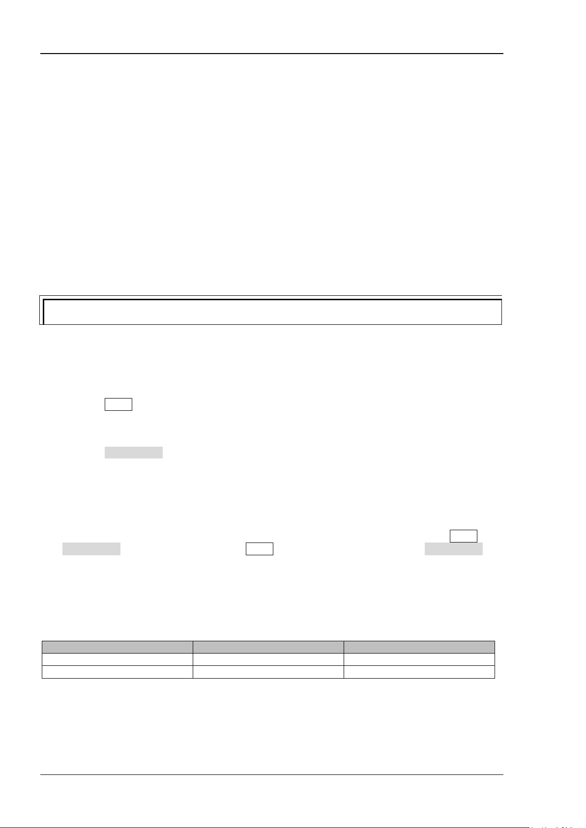
Format Conventions in this Manual:
1. Key:
The key at the front panel is deno ted by the format o f "Key Name (Bold) +Text Box" in the manual. For
example, FREQ denotes the FREQ key.
2. Menu:
The menu is denoted by the format of "Menu Word (Bold) + Character Shading" in the manual. For
example, Center Freq denotes the center frequency menu item under the FREQ function key.
3. Connector:
The connector at the front or rear panel is denoted by the format of "Connector Name (Bold) + Square
Brackets (Bold)" in the manual. For example, [GEN OUTPUT 50Ω].
4. Operation step:
The operation for the next ste p is denoted by an arrow "" in t he manual. For example, FREQ
Center Freq denotes that you first press FREQ on the front panel and then press Ce nt er Fr e q.
Content Conventions in this Manual:
DSA700 series spectrum analyzer includes the following two models. The introductions of the DSA700
series commands in this manual are based on DSA710, unless otherwise noted.
DSA705 100 kHz to 500 MHz None
DSA710 100 kHz to 1 GHz None
VIII DSA700 Programming Guide

Contents RIGOL
Contents
Guaranty and Declaration ......................................................................................................... I
Safety Requirement .................................................................................................................. II
General Safety Summary ............................................................................................................. II
Safety Notices and Symbols ......................................................................................................... IV
Allgemeine Sicherheits Informationen ........................................................................................... V
Sicherheits Begri ffe und Symbole ............................................................................................... VII
Document Overview ............................................................................................................. VIII
Chapter 1 SCPI Overview .................................................................................................... 1-1
Syntax ..................................................................................................................................... 1-2
Symbol Description ................................................................................................................... 1-2
Parameter Type ........................................................................................................................ 1-3
Command Abbreviation ............................................................................................................. 1-3
Chapter 2 Command System ............................................................................................... 2-1
:ABORt..................................................................................................................................... 2-2
:CALCulate Subsystem .............................................................................................................. 2-2
:CALCulate:BANDwidth:NDB ............................................................................................... 2-4
:CALCulate:BANDwidth:RESult?........................................................................................... 2-4
:CALCulate:LLINe:ALL:DELete ............................................................................................. 2-4
:CALCulate:LLINe:CONTrol:DOMain ..................................................................................... 2-5
:CALCulate:LLINe:FAIL? ...................................................................................................... 2-5
:CALCulate:LLINe:FAIL:RATIo?............................................................................................ 2-6
:CALCulate:LLINe:FAIL:STOP:STATe .................................................................................... 2-6
:CALCulate:LLINe<n>:CONTrol:INTerpolate:TYPE ................................................................ 2-7
:CALCulate:LLINe<n>:DATA ............................................................................................... 2-7
:CALCulate:LLINe<n>:DATA:MERGe ................................................................................... 2-8
:CALCulate:LLINe<n>:DELete ............................................................................................ 2-9
:CALCulate:LLINe<n>:RELAmpt[:STATe] ............................................................................. 2-9
:CALCulate:LLINe<n>:RELFreq[:STATe] ............................................................................ 2-10
:CALCulate:LLINe<n>:STATe ............................................................................................ 2-10
:CALCulate:MARKer:AOFF ................................................................................................. 2-11
:CALCulate:MARKer:FCOunt:RESolution ............................................................................. 2-11
:CALCulate:MARKer:FCOunt:RESolution:AUTO ................................................................... 2-12
:CALCulate:MARKer:FCOunt:X? ......................................................................................... 2-12
:CALCulate:MARKer:FCOunt[:STATe] ................................................................................. 2-13
:CALCulate:MARKer<n>:CPEak[:STATe] ............................................................................ 2-13
:CALCulate:MARKer<n>:DELTa[:SET]:CENTer .................................................................... 2-14
:CALCulate:MARKer<n>:DELTa[:SET]:SPAN ....................................................................... 2-14
:CALCulate:MARKer<n>:FUNCtion .................................................................................... 2-15
:CALCulate:MARKer<n>:MAXimum:LEFT ........................................................................... 2-15
:CALCulate:MARKer<n>:MAXimum:MAX ............................................................................ 2-16
:CALCulate:MARKer<n>:MAXimum:NEXT .......................................................................... 2-16
:CALCulate:MARKer<n>:MAXimum:RIGHt ......................................................................... 2-16
:CALCulate:MARKer<n>:MINimum .................................................................................... 2-17
:CALCulate:MARKer<n>:MODE ......................................................................................... 2-17
:CALCulate:MARKer<n>:PEAK:EXCursion .......................................................................... 2-18
:CALCulate:MARKer<n>:PEAK:SEARch:MODE .................................................................... 2-18
:CALCulate:MARKer<n>:PEAK[:SET]:CF ............................................................................ 2-19
:CALCulate:MARKer<n>:PEAK:THReshold ......................................................................... 2-19
:CALCulate:MARKer<n>:PTPeak ....................................................................................... 2-20
:CALCulate:MARKer<n>[:SET]:CENTer .............................................................................. 2-20
:CALCulate:MARKer<n>[:SET]:RLEVel ............................................................................... 2-21
:CALCulate:MARKer<n>[:SET]:STARt ................................................................................ 2-21
:CALCulate:MARKer<n>[:SET]:STEP ................................................................................. 2-22
DSA700 编程手册 IX

RIGOL Contents
:CALCulate:MARKer<n>[:SET]:STOP ................................................................................. 2-22
:CALCulate:MARKer<n>:STATe .......................................................................................... 2-23
:CALCulate:MARKer<n>:TRACe ......................................................................................... 2-23
:CALCulate:MARKer<n>:TRACe:AUTO ............................................................................... 2-24
:CALCulate:MARKer<n>:X ................................................................................................ 2-25
:CALCulate:MARKer<n>:X:CENTer ..................................................................................... 2-26
:CALCulate:MARKer<n>:X:POSition ................................................................................... 2-27
:CALCulate:MARKer<n>:X:POSition:CENTer ....................................................................... 2-27
:CALCulate:MARKer<n>:X:POSition:SPAN .......................................................................... 2-28
:CALCulate:MARKer<n>:X:POSition:STARt ......................................................................... 2-28
:CALCulate:MARKer<n>:X:POSition:STOP .......................................................................... 2-29
:CALCulate:MARKer<n>:X:READout .................................................................................. 2-29
:CALCulate:MARKer<n>:X:SPAN ....................................................................................... 2-30
:CALCulate:MARKer<n>:X:STARt....................................................................................... 2-30
:CALCulate:MARKer<n>:X:STOP ....................................................................................... 2-31
:CALCulate:MARKer<n>:Y? ............................................................................................... 2-32
:CALCulate:MARKer:TABLe:STATe ...................................................................................... 2-32
:CALCulate:MARKer:TRACking:STATe ................................................................................. 2-33
:CALibration Subsystem ........................................................................................................... 2-34
:CALibration:[ALL] ............................................................................................................ 2-34
:CALibration:AUTO ............................................................................................................ 2-34
:CONFigure Subsystem ............................................................................................................ 2-35
:CONFigure? ..................................................................................................................... 2-35
:CONFigure:ACPower ........................................................................................................ 2-35
:CONFigure:CHPower ........................................................................................................ 2-36
:CONFigure:CNRatio ......................................................................................................... 2-36
:CONFigure:EBWidth......................................................................................................... 2-36
:CONFigure:HDISt ............................................................................................................ 2-37
:CONFigure:OBWidth ........................................................................................................ 2-37
:CONFigure:PF ................................................................................................................. 2-37
:CONFigure:SANalyzer ...................................................................................................... 2-37
:CONFigure:TOI ............................................................................................................... 2-38
:CONFigure:TPOWer ......................................................................................................... 2-38
:COUPle Subsystem ................................................................................................................. 2-39
:COUPle ........................................................................................................................... 2-39
:DISPlay Subsystem ................................................................................................................ 2-40
:DISPlay:AFUnction:POSition ............................................................................................. 2-41
:DISPlay:ANNotation:CLOCk[:STATe] ................................................................................. 2-41
:DISPlay:BRIGhtness ........................................................................................................ 2-42
:DISPlay:ENABle ............................................................................................................... 2-42
:DISPlay:MSGswitch:STATe ............................................................................................... 2-43
:DISPlay:UKEY:STATe ........................................................................................................ 2-43
:DISPlay:WINdow:TRACe:GRATicule:GRID ......................................................................... 2-44
:DISPlay:WINdow:TRACe:X[:SCALe]:SPACing .................................................................... 2-44
:DISPlay:WINdow:TRACe:Y:DLINe ..................................................................................... 2-45
:DISPlay:WINdow:TRACe:Y:DLINe:STATe ........................................................................... 2-45
:DISPlay:WINdow:TRACe:Y[:SCALe]:PDIVision .................................................................. 2-46
:DISPlay:WINdow:TRACe:Y[:SCALe]:RLEVel....................................................................... 2-46
:DISPlay:WINdow:TRACe:Y[:SCALe]:RLEVel:OFFSet ........................................................... 2-47
:DISPlay:WINdow:TRACe:Y[:SCALe]:SPACing .................................................................... 2-47
:FETCh Subsystem .................................................................................................................. 2-48
:FETCh:ACPower? ............................................................................................................. 2-49
:FETCh:ACPower:LOWer? .................................................................................................. 2-49
:FETCh:ACPower:MAIN? ................................................................................................... 2-50
:FETCh:ACPower:UPPer? ................................................................................................... 2-50
:FETCh:CHPower? ............................................................................................................ 2-51
:FETCh:CHPower:CHPower? .............................................................................................. 2-51
:FETCh:CHPower:DENSity? ................................................................................................ 2-52
X DSA700 Programming Guide

Contents RIGOL
:FETCh:CNRatio? .............................................................................................................. 2-52
:FETCh:CNRatio:CARRier?................................................................................................. 2-53
:FETCh:CNRatio:CNRatio? ................................................................................................. 2-53
:FETCh:CNRatio:NOISe? ................................................................................................... 2-54
:FETCh:EBWidth? ............................................................................................................. 2-54
:FETCh:HARMonics:AMPLitude:ALL? .................................................................................. 2-55
:FETCh:HARMonics :AMP L it ude ? <n > ................................................................................. 2-55
:FETCh:HARMonics[:DISTortion]? ...................................................................................... 2-56
:FETCh:HARMonics:FREQuency:ALL? ................................................................................. 2-56
:FETCh:HARMonics :FRE Q ue ncy ? <n > ............................................................................... 2-57
:FETCh:HARMonics:FUNDamental? .................................................................................... 2-57
:FETCh:OBWidth? ............................................................................................................ 2-58
:FETCh:OBWidth:OBWidth? .............................................................................................. 2-58
:FETCh:OBWidth:OBWidth:FERRor? .................................................................................. 2-59
:FETCh:TOIntercept? ........................................................................................................ 2-59
:FETCh:TOIntercept:IP3? .................................................................................................. 2-60
:FETCh:TPOWer? ............................................................................................................. 2-60
:FORMat Subsystem................................................................................................................ 2-61
:FORMat:BORDer ............................................................................................................. 2-61
:FORMat[:TRACe][:DATA] ................................................................................................. 2-62
:HCOPy Subsystem ................................................................................................................. 2-63
:HCOPy:ABORt ................................................................................................................. 2-63
:HCOPy:IMAGe:COLor[:STATe] .......................................................................................... 2-63
:HCOPy:IMAGe:FTYPe ...................................................................................................... 2-64
:HCOPy:IMAGe:INVert ...................................................................................................... 2-64
:HCOPy:IMAGe:PTIMe ...................................................................................................... 2-65
:HCOPy:IMAGe:QUALity ................................................................................................... 2-65
:HCOPy[:IMMediate] ........................................................................................................ 2-66
:HCOPy:PAGE:ORIentation ............................................................................................... 2-66
:HCOPy:PAGE:PRINts ....................................................................................................... 2-67
:HCOPy:PAGE:SIZE .......................................................................................................... 2-67
:HCOPy:RESume .............................................................................................................. 2-68
IEEE 488.2 Common Commands.............................................................................................. 2-69
*CLS ............................................................................................................................... 2-69
*ESE ............................................................................................................................... 2-69
*ESR? ............................................................................................................................. 2-70
*IDN? ............................................................................................................................. 2-70
*OPC ............................................................................................................................... 2-71
*RST ............................................................................................................................... 2-71
*SRE ............................................................................................................................... 2-71
*STB? ............................................................................................................................. 2-72
*TRG .............................................................................................................................. 2-72
*TST? ............................................................................................................................. 2-72
*WAI ............................................................................................................................... 2-72
:INITiate Subsystem ............................................................................................................... 2-73
:INITiate:CONTinuous ...................................................................................................... 2-73
:INITiate[:IMMediate] ...................................................................................................... 2-74
:INITiate:PAUSe ............................................................................................................... 2-74
:INITiate:RESTart ............................................................................................................. 2-74
:INITiate:RESume ............................................................................................................ 2-74
:INPut Subsystem ................................................................................................................... 2-75
:INPut:IMPedance ............................................................................................................ 2-75
:MMEMory Subsystem ............................................................................................................. 2-76
:MMEMory:DELete ............................................................................................................ 2-76
:MMEMory:DISK:INFormation? .......................................................................................... 2-77
:MMEMory:LOAD:CORRection ........................................................................................... 2-77
:MMEMory:LOAD:LIMit ..................................................................................................... 2-78
:MMEMory:LOAD:MTABle .................................................................................................. 2-78
DSA700 Programming Guide XI

RIGOL Contents
:MMEMory:LOAD:SETUp ................................................................................................... 2-79
:MMEMory:LOAD:STATe .................................................................................................... 2-79
:MMEMory:LOAD:TRACe ................................................................................................... 2-80
:MMEMory:MOVE .............................................................................................................. 2-80
:MMEMory:STORe:CORRection .......................................................................................... 2-81
:MMEMory:STORe:LIMit .................................................................................................... 2-81
:MMEMory:STORe:MTABle................................................................................................. 2-82
:MMEMory:STORe:PTABle ................................................................................................. 2-82
:MMEMory:STORe:RESults ................................................................................................ 2-83
:MMEMory:STORe:SCReen ................................................................................................ 2-83
:MMEMory:STORe:SETUp .................................................................................................. 2-84
:MMEMory:STORe:STATe ................................................................................................... 2-84
:MMEMory:STORe:TRACe .................................................................................................. 2-85
:READ Subsystem ................................................................................................................... 2-86
:READ:ACPower? .............................................................................................................. 2-87
:READ:ACPower:LOWer? ................................................................................................... 2-87
:READ:ACPower:MAIN? ..................................................................................................... 2-87
:READ:ACPower:UPPer? .................................................................................................... 2-88
:READ:CHPower? .............................................................................................................. 2-88
:READ:CHPower:CHPower? ............................................................................................... 2-88
:READ:CHPower:DENSity? ................................................................................................. 2-89
:READ:CNRatio? ............................................................................................................... 2-89
:READ:CNRatio:CARRier? .................................................................................................. 2-89
:READ:CNRatio:CNRatio? .................................................................................................. 2-90
:READ:CNRatio:NOISe?..................................................................................................... 2-90
:READ:EBWidth? .............................................................................................................. 2-90
:READ:HARMonics:AMPLitude:ALL? ................................................................................... 2-91
:READ:HARMonics:AMPLitude? <n> .................................................................................. 2-91
:READ:HARMonics[:DISTortion]? ....................................................................................... 2-92
:READ:HARMonics:FREQuency:ALL? .................................................................................. 2-92
:READ:HARMonics:FREQuency? <n > ................................................................................. 2-93
:READ:HARMonics:FUNDamental? ..................................................................................... 2-93
:READ:OBWidth? .............................................................................................................. 2-93
:READ:OBWidth:OBWidth? ................................................................................................ 2-94
:READ:OBWidth:OBWidth:FERRor? .................................................................................... 2-94
:READ:TOIntercept? ......................................................................................................... 2-94
:READ:TOIntercept:IP3? ................................................................................................... 2-95
:READ:TPOWer? ............................................................................................................... 2-95
[:SENSe] Subsystem ............................................................................................................... 2-96
[:SENSe]:ACPower:AVERage:COUNt .................................................................................. 2-99
[:SENSe]:ACPower:AVERage[:STATe] ................................................................................. 2-99
[:SENSe]:ACPower:AVERage:TCONtrol ............................................................................. 2-100
[:SENSe]:ACPower:BANDwidth:ACHannel ........................................................................ 2-100
[:SENSe]:ACPower:BANDwidth:INTegration...................................................................... 2-101
[:SENSe]:ACPower:CSPacing ........................................................................................... 2-102
[:SENSe]:BANDwidth:EMIFilter:STATe .............................................................................. 2-102
[:SENSe]:BANDwidth[:RESolution]................................................................................... 2-103
[:SENSe]:BANDwidth[:RESolution]:AUTO ......................................................................... 2-103
[:SENSe]:BANDwidth:VIDeo ............................................................................................ 2-104
[:SENSe]:BANDwidth:VIDeo:AUTO .................................................................................. 2-104
[:SENSe]:BANDwidth:VIDeo:RATio .................................................................................. 2-105
[:SENSe]:CHPower:AVERage:COUNt ................................................................................ 2-105
[:SENSe]:CHPower:AVERage[:STATe] .............................................................................. 2-106
[:SENSe]:CHPower:AVERage:TCONtrol ............................................................................ 2-106
[:SENSe]:CHPower:BANDwidth:INTegration ..................................................................... 2-107
[:SENSe]:CHPower:FREQuency:SPAN .............................................................................. 2-107
[:SENSe]:CNRatio:AVERage:COUNt ................................................................................. 2-108
[:SENSe]:CNRatio:AVERage[:STATe] ................................................................................ 2-109
XII DSA700 Programming Guide

Contents RIGOL
[:SENSe]:CNRatio:AVERage:TCONtrol .............................................................................. 2-109
[:SENSe]:CNRatio:BANDwidth:INTegration ...................................................................... 2-110
[:SENSe]:CNRatio:BANDwidth:NOISe .............................................................................. 2-111
[:SENSe]:CNRatio:OFFSet ............................................................................................... 2-111
[:SENSe]:CORRection:CSET:ALL:DELete .......................................................................... 2-112
[:SENSe]:CORRection:CSET:ALL[:STATe] ......................................................................... 2-112
[:SENSe]:CORRection:CSET<n>:DATA ............................................................................ 2-113
[:SENSe]:CORRection:CSET<n>:DATA:MERGe ................................................................. 2-113
[:SENSe]:CORRection:CSET<n>:DELete .......................................................................... 2-114
[:SENSe]:CORRection:CSET<n>[:STATe] ......................................................................... 2-114
[:SENSe]:CORRection:CSET<n>:X:SPACing ..................................................................... 2-115
[:SENSe]:CORRection:CSET:TABLe:STATe ........................................................................ 2-115
[:SENSe]:DEMod ............................................................................................................ 2-116
[:SENSe]:DEMod:GAIN:AUTO ......................................................................................... 2-116
[:SENSe]:DEMod:GAIN:INCRement ................................................................................. 2-117
[:SENSe]:DEMod:STATe .................................................................................................. 2-117
[:SENSe]:DEMod:TIME ................................................................................................... 2-118
[:SENSe]:DETector[:FUNCtion] ....................................................................................... 2-118
[:SENSe]:EBWidth:AVERage:COUNt ................................................................................ 2-119
[:SENSe]:EBWidth:AVERage[:STATe] ............................................................................... 2-120
[:SENSe]:EBWidth:AVERage:TCONtrol ............................................................................. 2-120
[:SENSe]:EBWidth:FREQuency:SPAN ............................................................................... 2-121
[:SENSe]:EBWidth:MAXHold:STATe ................................................................................. 2-122
[:SENSe]:EBWidth:XDB .................................................................................................. 2-122
[:SENSe]:EXTRef[:STATe]? ............................................................................................. 2-123
[:SENSe]:FREQuency:CENTer.......................................................................................... 2-123
[:SENSe]:FREQuency:CENTer:DOWN .............................................................................. 2-124
[:SENSe]:FREQuency:CENTer:SET:STEP .......................................................................... 2-124
[:SENSe]:FREQuency:CENTer:STEP:AUTO ....................................................................... 2-124
[:SENSe]:FREQuency:CENTer:STEP[:INCRement] ............................................................ 2-125
[:SENSe]:FREQuency:CENTer:UP .................................................................................... 2-125
[:SENSe]:FREQuency:OFFSet .......................................................................................... 2-125
[:SENSe]:FREQuency:SPAN ............................................................................................ 2-126
[:SENSe]:FREQuency:SPAN:FULL .................................................................................... 2-126
[:SENSe]:FREQuency:SPAN:PREVious ............................................................................. 2-127
[:SENSe]:FREQuency:SPAN:ZIN ...................................................................................... 2-127
[:SENSe]:FREQuency:SPAN:ZOUT ................................................................................... 2-127
[:SENSe]:FREQuency:STARt ........................................................................................... 2-127
[:SENSe]:FREQuency:STOP ............................................................................................ 2-128
[:SENSe]:HDISt:AVERage:COUNt .................................................................................... 2-128
[:SENSe]:HDISt:AVERage[:STATe] .................................................................................. 2-129
[:SENSe]:HDISt:AVERage:TCONtrol ................................................................................. 2-129
[:SENSe]:HDISt:NUMBers ............................................................................................... 2-130
[:SENSe]:HDISt:TIME ..................................................................................................... 2-131
[:SENSe]:HDISt:TIME:AUTO[:STATe] .............................................................................. 2-131
[:SENSe]:OBWidth:AVERage:COUNt ................................................................................ 2-132
[:SENSe]:OBWidth:AVERage[:STATe] .............................................................................. 2-132
[:SENSe]:OBWidth:AVERage:TCONtrol ............................................................................ 2-133
[:SENSe]:OBWidth:FREQuency:SPAN .............................................................................. 2-133
[:SENSe]:OBWidth:MAXHold:STATe ................................................................................. 2-134
[:SENSe]:OBWidth:PERCent ........................................................................................... 2-135
[:SENSe]:POWer:ARANge ............................................................................................... 2-135
[:SENSe]:POWer:ASCale ................................................................................................. 2-135
[:SENSe]:POWer:ATUNe ................................................................................................. 2-136
[:SENSe]:POWer[:RF]:ATTenuation ................................................................................. 2-136
[:SENSe]:POWer[:RF]:ATTenuation:AUTO ........................................................................ 2-137
[:SENSe]:POWer[:RF]:GAIN[:STATe] ............................................................................... 2-137
[:SENSe]:POWer[:RF]:MIXer:RANGe[:UPPer] ................................................................... 2-138
DSA700 Programming Guide XIII

RIGOL Contents
[:SENSe]:SIGCapture[:STATe] ......................................................................................... 2-138
[:SENSe]:SIGCapture:SIGC[:STATe] ................................................................................. 2-139
[:SENSe]:SIGCapture:MAXHold[:STATe] ........................................................................... 2-139
[:SENSe]:SIGCapture:RESet ............................................................................................ 2-140
[:SENSe]:SIGCapture:2FSK[:STATe] ................................................................................. 2-140
[:SENSe]:SIGCapture:2FSK:RESet ................................................................................... 2-140
[:SENSe]:SIGCapture:2FSK:MAXHold[:STATe] .................................................................. 2-141
[:SENSe]:SIGCapture:2FSK:PFSWitch .............................................................................. 2-141
[:SENSe]:SIGCapture:2FSK:SIGNal .................................................................................. 2-142
[:SENSe]:SIGCapture:2FSK:AMPUp.................................................................................. 2-142
[:SENSe]:SIGCapture:2FSK:AMPDown ............................................................................. 2-143
[:SENSe]:SIGCapture:2FSK:MARK1[:FREQ] ...................................................................... 2-143
[:SENSe]:SIGCapture:2FSK:MARK1:Switch[:STATe] .......................................................... 2-144
[:SENSe]:SIGCapture:2FSK:MARK2[:FREQ] ...................................................................... 2-144
[:SENSe]:SIGCapture:2FSK:MARK2:Switch[:STATe] .......................................................... 2-145
[:SENSe]:SWEep:COUNt ................................................................................................. 2-145
[:SENSe]:SWEep:COUNt:CURRent? ................................................................................. 2-146
[:SENSe]:SWEep:TIME ................................................................................................... 2-146
[:SENSe]:SWEep:TIME:AUTO .......................................................................................... 2-147
[:SENSe]:SWEep:TIME:AUTO:RULes ............................................................................... 2-147
[:SENSe]:TOI:AVERage:COUNt ........................................................................................ 2-148
[:SENSe]:TOI:AVERage[:STATe] ...................................................................................... 2-148
[:SENSe]:TOI:AVERage:TCONtrol .................................................................................... 2-149
[:SENSe]:TOI:FREQuency:SPAN ...................................................................................... 2-149
[:SENSe]:TPOWer:AVERage:COUNt ................................................................................. 2-150
[:SENSe]:TPOWer:AVERage[:STATe] ................................................................................ 2-150
[:SENSe]:TPOWer:AVERage:TCONtrol .............................................................................. 2-151
[:SENSe]:TPOWer:LLIMit ................................................................................................ 2-151
[:SENSe]:TPOWer:MODE ................................................................................................ 2-152
[:SENSe]:TPOWer:RLIMit ................................................................................................ 2-153
:STATus Subsystem ............................................................................................................... 2-154
:STATus:OPERation:CONDition? ....................................................................................... 2-155
:STATus:OPERation:ENABle ............................................................................................. 2-155
:STATus:OPERation[:EVENt]? .......................................................................................... 2-156
:STATus:PRESet .............................................................................................................. 2-156
:STATus:QUEStionable:CONDition? .................................................................................. 2-156
:STATus:QUEStionable:ENABle......................................................................................... 2-157
:STATus:QUEStionable[:EVENt]? ...................................................................................... 2-157
:SYSTem Subsystem .............................................................................................................. 2-158
:SYSTem:BEEPer:STATe .................................................................................................. 2-159
:SYSTem:CLEar .............................................................................................................. 2-159
:SYSTem:COMMunicate:APORt ........................................................................................ 2-160
:SYSTem:COMMunicate:BRMT ......................................................................................... 2-160
:SYSTem:COMMunicate:GPIB[:SELF]:ADDRess ................................................................. 2-161
:SYSTem:COMMunicate:LAN[:SELF]:AUToip:STATe ............................................................ 2-161
:SYSTem:COMMunicate:LAN[:SELF]:DHCP:STATe ............................................................. 2-162
:SYSTem:COMMunicate:LAN[:SELF]:IP:ADDress ............................................................... 2-162
:SYSTem:COMMunicate:LAN[:SELF]:IP:DNSServer ............................................................ 2-163
:SYSTem:COMMunicate:LAN[:SELF]:IP:GATeway .............................................................. 2-163
:SYSTem:COMMunicate:LAN[:SELF]:IP:SUBMask .............................................................. 2-164
:SYSTem:COMMunicate:LAN[:SELF]:MANuip:STATe........................................................... 2-164
:SYSTem:COMMunicate:LAN[:SELF]:RESet ....................................................................... 2-165
:SYSTem:COMMunicate:USB[:SELF]:ADDRess? ................................................................. 2-165
:SYSTem:COMMunicate:USB[:SELF]:CLASs ....................................................................... 2-165
:SYSTem:CONFigure:INFormation? .................................................................................. 2-166
:SYSTem:CONFigure:MESSage? ....................................................................................... 2-166
:SYSTem:DATE ............................................................................................................... 2-167
:SYSTem:ERRor[:NEXT]? ................................................................................................. 2-167
XIV DSA700 Programming Guide

Contents RIGOL
:SYSTem:FSWItch[:STATe].............................................................................................. 2-168
:SYSTem:KLOCk ............................................................................................................. 2-168
:SYSTem:LANGuage ....................................................................................................... 2-169
:SYSTem:LINemod:STATe?.............................................................................................. 2-169
:SYSTem:LINemod:TYPe ................................................................................................. 2-170
:SYSTem:LKEY ............................................................................................................... 2-170
:SYSTem:OPTions? ......................................................................................................... 2-171
:SYSTem:PON:TYPE ....................................................................................................... 2-171
:SYSTem:PRESet ............................................................................................................ 2-172
:SYSTem:PRESet:SAVE ................................................................................................... 2-172
:SYSTem:PRESet:TYPE ................................................................................................... 2-172
:SYSTem:SPEaker[:STATe] .............................................................................................. 2-173
:SYSTem:SPEaker:VOLume ............................................................................................. 2-173
:SYSTem:TIME ............................................................................................................... 2-174
:SYSTem:TX:STATe? ....................................................................................................... 2-174
:SYSTem:TX:SWset ........................................................................................................ 2-175
:SYSTem:TX:SWSTa? ...................................................................................................... 2-175
:SYSTem:USERkey:CONFirm ........................................................................................... 2-176
:SYSTem:USERkey:KEYCmd ............................................................................................ 2-176
:SYSTem:USERkey:STATe ............................................................................................... 2-177
:SYSTem:VERSion? ......................................................................................................... 2-177
:TRACe Subsystem ............................................................................................................... 2-178
:TRACe:AVERage:CLEar .................................................................................................. 2-178
:TRACe:AVERage:COUNt ................................................................................................ 2-178
:TRACe:AVERage:COUNt:CURRent?................................................................................. 2-179
:TRACe:AVERage:RESet ................................................................................................. 2-179
:TRACe:CLEar:ALL ......................................................................................................... 2-179
:TRACe[:DATA] .............................................................................................................. 2-180
:TRACe:MATH:A ............................................................................................................. 2-181
:TRACe:MATH:B ............................................................................................................. 2-181
:TRACe:MATH:CONSt ..................................................................................................... 2-182
:TRACe:MATH:PEAK[:DATA]? .......................................................................................... 2-182
:TRACe:MATH:PEAK:POINts? .......................................................................................... 2-183
:TRACe:MATH:PEAK:SORT .............................................................................................. 2-183
:TRACe:MATH:PEAK:TABLe:STATe ................................................................................... 2-183
:TRACe:MATH:PEAK:THReshold ...................................................................................... 2-184
:TRACe:MATH:STATe ...................................................................................................... 2-184
:TRACe:MATH:TYPE ....................................................................................................... 2-185
:TRACe<n>:AVERage:TYPE ............................................................................................ 2-185
:TRACe<n>:MODE ......................................................................................................... 2-186
:TRIGger Subsystem ............................................................................................................. 2-187
:TRIGger:SEQuence:EXTernal:READy? ............................................................................. 2-187
:TRIGger:SEQuence:EXTernal:SLOPe ............................................................................... 2-187
:TRIGger:SEQuence:SOURce .......................................................................................... 2-188
:TRIGger:SEQuence:VIDeo:LEVel .................................................................................... 2-189
:UNIT Subsystem.................................................................................................................. 2-190
:UNIT:POWer ................................................................................................................. 2-190
Chapter 3 Programming Demos .......................................................................................... 3-1
Programming Instructions ......................................................................................................... 3-2
Programming Preparations ........................................................................................................ 3-2
Visual C++ 6.0 Programming Demo ........................................................................................... 3-5
Visual Basic 6.0 Programming Demo ........................................................................................ 3-13
LabVIEW 8.6 Programming Demo ............................................................................................ 3-17
Linux Programming Demo ....................................................................................................... 3-21
Linux Programming Preparations ....................................................................................... 3-21
Linux Programming Procedures ......................................................................................... 3-24
DSA700 Programming Guide XV


Chapter 1 SCPI Overview RIGOL
Chapter 1 SCPI Overview
SCPI (Standard Commands for Programmable Instruments) is standardized instrument programming
language that is bas ed on the stan dard IEEE48 8.1 and IEEE 4 88.2 and conform s to v arious stard ards (such
as the floating point operation rule in IEEE754 stardard, ISO646 7-bit coded character for information
interchange (equivalent to ASCll programming).
Main topics of this chapter:
Syntax
Symbol Description
Parameter Type
Command Abbreviation
DSA700 Programming Guide 1-1

RIGOL Chapter 1 SCPI Overview
Syntax
SCPI commands present a hierarchical tree structure and contain multiple sub-systems, each of which is
made up of a root keyword and one or more sub-keywords. The command string usually starts with ":", the
keywords are separated by ":" and are followed by the parameter settings availab le, "?" is added at the end
of the command string to indicate query and the command and parameter are separated by a space.
For example,
:CALCulate:BANDwidth:NDB <rel_ampl>
:CALCulate:BANDwidth:NDB?
CALCulate is the r oot keyword of the command. BANDwidth and NDB are the second-level and
third-level keywords respectively. The command string starts with ":" which separate s the multiple-level
keywords. <rel_ampl> represents the parameter available for setting, "?" represents query and the
command :CALCulate:BANDwidth:NDB and parameter <rel_ampl> are separated by a space.
"," is generally used for separating different parameters contained in the same command, for example,
:SYSTem:DATE <yea r>,<month>, <d a y >
Symbol Description
The following four symbols are not the content of SCPI commands and will not be sent with the commands,
but are usually used to describe the parameters in the commands.
Braces { }
The parameters enclosed in the braces are optional and can be ignored or set for one or more times. For
example,
In the [:SENSe]:CORRection:CSET<n>:DATA <freq>,<rel_ampl>{,<freq>,<rel_ampl>} command, the
frequency and amplitude in {,<freq>,<rel_ampl>} can be omitted or be set to one or more values.
Vertical Bar |
The vertical bar is u sed to separ ate multip le par ameter s and o ne of the par ameters mu st be selec ted when
sending the command. For example,
In the :DISPlay:ANNotation:CLOCk[:STATe] OFF|ON|0|1 command, the command parameters a vailabl e are
"OFF", "ON", "0" or "1".
Square Brackets [ ]
The content (command keyword) enclosed in the square brackets can be omitted. For example,
for the [:SENSe]:POWer[:RF]:ATTenuation? command, sending any of the four commands below can
generate the same effect:
:POWer:ATTenuation?
:POWer:RF:ATTenuation?
:SENSe:POWer:ATTenuation?
:SENSe:POWer:RF:ATTenuation?
Triangle Brackets < >
The parameter enclosed in the triangle brackets must be replaced by an effective value. For example,
send the :DISPlay:BRIGhtness <integer> command in :DISPlay:BRIGhtness 5 format.
1-2 DSA700 Programming Guide

Chapter 1 SCPI Overview RIGOL
Parameter Type
The command parameters introduced in this manual include 6 types: Bool, Keyword, Integer, Consecutive
Real Number, Discrete and ASCII String.
Bool
The parameter could be "OFF", "ON", "0" or "1". For example,
:DISPlay:ANNotation:CLOCk[:STATe] OFF|ON|0|1
Keyword
The parameter could be any of the values listed. For example,
:DISPlay:AFUnction:POSition BOTTom|CENTer|TOP
The parameter could be "BOTTom", "CENTer" or "TOP".
Integer
Unless otherwise noted, the parameter c an be any integer within the effective value range. Note that do not
set the parameter to a decimal; otherwise errors will occur. For example,
:DISPlay:BRIGhtnes s <integer>
<integer> can be set to any integer between 0 and 10.
Consecutive Real Number
The parameter could be any value within the effective value range according to the accuracy requirement
(by default, there are 6 digits after the decimal points). For example,
:CALCulate:BANDwidth:NDB <rel_ampl>
<rel_ampl> can be set to any real number between -100 and 100.
Discrete
The parameter could on ly be one of th e specified values and these v alues are di scon tinu ous. F o r ex ample,
:CALCulate:MARKer<n>:MAXimum:MAX
<n> could only be set to 1, 2, 3 or 4.
ASCII String
The parameter should be the combinations of ASCII characters. For example,
:SYSTem:DATE <year>,<month>,<day>
The parameter is a string in the specified date format.
Command Abbreviation
Since all the commands are case-insensitive, you can use any of them. But if abbreviation is used, all the
capital letters in the command must be written completely. For example,
:CALCulate:BANDwidth:NDB? can be abbreviated to :CALC:BAND:NDB?
DSA700 Programming Guide 1-3


Chapter 2 Command System RIGOL
Chapter 2 Command System
In this chapter, the DSA700 series spectrum analyzer comm and subsystems are introduced in alphabetical
order (from A to Z).
Main topics of this chapter:
:ABORt
:CALCulate Subsystem
:CALibration Subsystem
:CONFigure Subsystem
:COUPle Subsystem
:DISPlay Subsystem
:FETCh Subsystem
:FORMat Subsystem
:HCOPy Subsystem
IEEE 488.2 Common Commands
:INITiate Subsystem
:INPut Subsystem
:MMEMory Subsystem
:READ Subsystem
[:SENSe] Subsystem
:STATus Subsystem
:SYSTem Subsystem
:TRACe Subsystem
:TRIGger Subsystem
:UNIT Subsystem
Explanation:
1. In this command set, commands relating to Quasi-peak detector, EMI filter, advanced measurement,
Sig Capture and TX1000 are only applicable to DSA700 installed with the corresponding options. For
the details, refer to the explanation in each command subsystem.
2. In this command set, unless otherwise noted, the query returns "N/A" (quotation marks excluded) if
the corresponding option is not installed and returns "ERR" (quotation marks excluded) if th e
corresponding fu nction is not enabled or the type does not match.
3. In this manual, the parameter ranges of the commands are based on DSA710.
DSA700 Programming Guide 2-1

RIGOL Chapter 2 Command System
:ABORt
Syntax
:ABORt
Description
Give up the current operation and restart the sweep.
:CALCulate Subsystem
Command List:
:CALCulate:BANDwidth:NDB
:CALCulate:BANDwidth:RESult?
:CALCulate:LLINe:ALL:DELete
:CALCulate:LLINe:CONTrol:DOMain
:CALCulate:LLINe:FAIL?
:CALCulate:LLINe:FAIL:RATIo?
:CALCulate:LLINe:FAIL:STOP:STATe
:CALCulate:LLINe<n>:CONTrol:INTerpolate:TYPE
:CALCulate:LLINe<n>:DATA
:CALCulate:LLINe<n>:DATA:MERGe
:CALCulate:LLINe<n>:DELete
:CALCulate:LLINe<n>:RELAmpt[:STATe]
:CALCulate:LLINe<n>:RELFreq[:STATe]
:CALCulate:LLINe<n>:STATe
:CALCulate:MARKer:AOFF
:CALCulate:MARKer:FCOunt:RESolution
:CALCulate:MARKer:FCOunt:RESolution:AUTO
:CALCulate:MARKer:FCOunt:X?
:CALCulate:MARKer:FCOunt[:STATe]
:CALCulate:MARKer<n>:CPEak[:STATe]
:CALCulate:MARKer<n>:DELTa[:SET]:CENTer
:CALCulate:MARKer<n>:DELTa[:SET]:SPAN
:CALCulate:MARKer<n>:FUNCtion
:CALCulate:MARKer<n>:MAXimum:LEFT
:CALCulate:MARKer<n>:MAXimum:MAX
:CALCulate:MARKer<n>:MAXimum:NEXT
:CALCulate:MARKer<n>:MAXimum:RIGHt
:CALCulate:MARKer<n>:MINimum
:CALCulate:MARKer<n>:MODE
2-2 DSA700 Programming Guide

Chapter 2 Command System RIGOL
:CALCulate:MARKer<n>:PEAK:EXCursion
:CALCulate:MARKer<n>:PEAK:SEARch:MODE
:CALCulate:MARKer<n>:PEAK[:SET]:CF
:CALCulate:MARKer<n>:PEAK:THReshold
:CALCulate:MARKer<n>:PTPeak
:CALCulate:MARKer<n>[:SET]:CENTer
:CALCulate:MARKer<n>[:SET]:RLEVel
:CALCulate:MARKer<n>[:SET]:STARt
:CALCulate:MARKer<n>[:SET]:STEP
:CALCulate:MARKer<n>[:SET]:STOP
:CALCulate:MARKer<n>:STATe
:CALCulate:MARKer<n>:TRACe
:CALCulate:MARKer<n>:TRACe:AUTO
:CALCulate:MARKer<n>:X
:CALCulate:MARKer<n>:X:CENTer
:CALCulate:MARKer<n>:X:POSition
:CALCulate:MARKer<n>:X:POSition:CENTer
:CALCulate:MARKer<n>:X:POSition:SPAN
:CALCulate:MARKer<n>:X:POSition:STARt
:CALCulate:MARKer<n>:X:POSition:STOP
:CALCulate:MARKer<n>:X:READout
:CALCulate:MARKer<n>:X:SPAN
:CALCulate:MARKer<n>:X:STARt
:CALCulate:MARKer<n>:X:STOP
:CALCulate:MARKer<n>:Y?
:CALCulate:MARKer:TABLe:STATe
:CALCulate:MARKer:TRACking:STATe
DSA700 Programming Guide 2-3

RIGOL Chapter 2 Command System
Name
Type
Range
Default
:CALCulate:BANDwidth:NDB
Syntax
:CALCulate:BANDwidth:NDB <rel_ampl>
:CALCulate:BANDwidth:NDB?
Description
Set the value of N in N dB bandwidth measurement.
Query the value of N in N dB bandwidth measurement.
Parameter
<rel_ampl> Consecutive Real Number -100 dB to 100 dB -3 dB
Return Format
The query returns the value of N in scientific notation.
Example
The command below sets N to -4.
:CALCulate:BANDwidth:NDB -4
The query below returns -4.000000E+00.
:CALCulate:BANDwidth:NDB?
:CALCulate:BANDwidth:RESult?
Syntax
:CALCulate:BANDwidth:RESult?
Description
Query the measurement result of N dB bandwidth and the unit is Hz.
Return Format
The query returns the bandwidth in integer (in Hz).
If points that are located on both sides of the current marker and with N dB fall or rise in amplitude are not
found, the query returns ----.
:CALCulate:LLINe:ALL:DELete
Syntax
:CALCulate:LLINe:ALL:DELete
Description
Delete the limit line currently edited.
2-4 DSA700 Programming Guide

Chapter 2 Command System RIGOL
Name
Type
Range
Default
:CALCulate:LLINe:CONTrol:DOMain
Syntax
:CALCulate:LLINe:CONTrol:DOMain FREQuency|TIME
:CALCulate:LLINe:CONTrol:DOMain?
Description
Set the X axis to denote frequency or time in the Pass/Fail test.
Query the type of the X axis in the Pass/Fail test.
Parameter
Explanation
This setting is applicable to both the upper and lower limit lines.
All the points of the current limit line will be deleted when the X axis type is changed.
Return Format
The query returns FREQ or TIME.
Example
The command below sets the X axis to time.
:CALCulate:LLI Ne: C ON Tro l : DOM ai n TIME
The query below returns TIME.
:CALCulate:LLINe:CONTrol:DOMain?
-- Keyword FREQuency|TIME FREQuency
:CALCulate:LLINe:FAIL?
Syntax
:CALCulate:LLINe:FAIL?
Description
Query the result of the Pass/Fail test.
Return Format
The query returns PASS or FAIL. The quer y returns UNMEAS if the test is not finis hed.
DSA700 Programming Guide 2-5

RIGOL Chapter 2 Command System
Name
Type
Range
Default
--
Bool
OFF|ON|0|1
ON|1
:CALCulate:LLINe:FAIL:RATIo?
Syntax
:CALCulate:LLINe:FAIL:RATIo?
Description
Query the fail ratio of the Pass/Fail test.
Return Format
The query returns the fail ratio in scientific notation.
Example
The query below returns 5.490000E+00.
:CALCulate:LLINe:FAIL:RATIo?
:CALCulate:LLINe:FAIL:STOP:STATe
Syntax
:CALCulate:LLINe:FAIL:STOP:STATe OFF|ON|0|1
:CALCulate:LLINe:FAIL:STOP:STATe?
Description
Set whether to stop the test if the test fails.
Query whether to stop the test if the test fails.
Parameter
Explanation
If the parameter is set to ON or 1, the test sto ps when the test fail s and the test continu es if the parameter
is set to OFF or 0.
Return Format
The query returns 0 or 1.
Example
The command below sets the instrument to stop the test when the test fails.
:CALCulate:LLINe:FAIL:STOP:STATe ON or :CALCu la t e:LLI Ne : FAI L :S TOP: STATe 1
The query below returns 1.
:CALCulate:LLINe:FAIL:STOP:STATe?
2-6 DSA700 Programming Guide

Chapter 2 Command System RIGOL
Name
Type
Range
Default
--
Keyword
LOGarithmic|LINear
LINear
Name
Type
Range
Default
<n>
Discrete
1|2
2
Consecutive
0 Hz to 1 GHz (the X axis denotes frequency)
:CALCulate:LLINe<n>:CONTrol:INTerpolate:TYPE
Syntax
:CALCulate:LLINe<n>:CONTrol :INTerpolate:TYPE LOGarithmic|LINear
:CALCulate:LLINe<n>:CONTrol:INTerpolate:TYPE?
Description
Set the frequency interpolation mode in the Pass/Fail test to log or linear.
Query the frequency interpolation mode.
Parameter
Explanation
<n> denotes the lower limit line (1) or upper limit line (2).
In log mode, both the frequency and amplitude use log unit to make interpolation operation.
In linear mode, the frequency uses a linear unit and the amplitude uses a log unit for interpolation
operation.
Return Format
The query returns LOG or LIN.
Example
The command below sets the frequency interpolation mode of the lower limit line to log.
:CALCulate:LLINe1:CONTrol:INTerpolate:TYPE LOGarithmic
The query below returns LOG.
:CALCulate:LLINe1:CONTrol:INTerpolate:TYPE?
<n> Discrete 1|2 --
:CALCulate:LLINe<n>:DATA
Syntax
:CALCulate:LLINe<n>:DATA <x-axis>,<ampl>,<connected>{,<x-axis>,<ampl>,<connected>}
:CALCulate:LLINe<n>:DATA?
Description
Create a limit line of the Pass/Fail test.
Query the limit line information.
Parameter
<x-axis>
<ampl>
<connected>
Explanation
<n>: denote the lower limit line (1) or upper limit line (2).
<x-axis>: the frequency or time (depend on the X axis type) of the point being edited.
<ampl>: the amplitude of the point being edited.
DSA700 Programming Guide 2-7
Real Number
Consecutive
Real Number
Discrete 0|1 0
0 us to 1 ks (the X axis denotes time)
-400 dBm to 320 dBm --
--
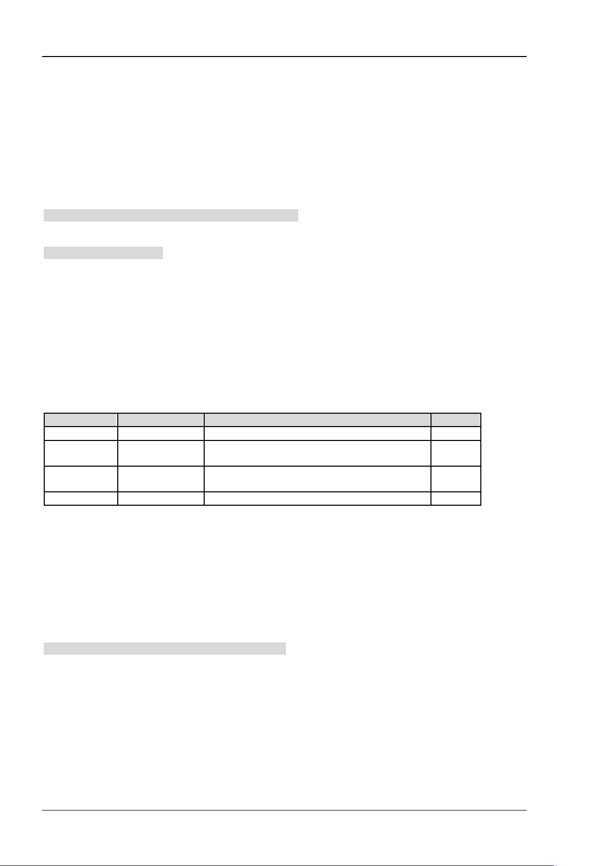
RIGOL Chapter 2 Command System
Name Type
Range
Default
<connected>
Discrete
0|1
0
<connected>: whether to connect the current point with the previous one. 1 denotes yes and 0 denotes no.
Note that for the first point, only 0 is available.
Up to 200 points can be edited for each limit line.
Return Format
The query returns the specified limit line information in
<x-axis>,<ampl>,<connected>{,<x-axis>,<ampl>,<connected>} format.
If no point is edited of the specified limit line, the query returns NULL.
Example
The command below creates an upper limit line wit h 3 points.
:CALCulate:LLI Ne2 :DATA 50,100,0,10 0,1 50 ,1, 20 0, 20 0, 1
The query below returns 50,100.000000,0,100,150.000000,1,200,200.000000,1.
:CALCulate:LLINe2:DATA?
:CALCulate:LLINe<n>:DATA:MERGe
Syntax
:CALCulate:LLINe<n>:DATA:MERGe <x-axis>,<ampl>,<connected>{,<x-axis>,<ampl>,<connected>}
Description
In the Pass/Fail test, add points onto the limit line being edited.
Parameter
<n> Discrete 1|2 2
<x-axis>
<ampl>
Consecutive
Real Number
Consecutive
Real Number
0 Hz to 1 GHz (X axis denotes frequency)
0 us to 1 ks (X axis denotes time)
-400 dBm to 320 dBm --
--
Explanation
<n>: denote the lower limit line (1) or upper limit line (2).
<x-axis>: the frequency or time (depend on the X axis type) of the point being edited.
<ampl>: the amplitude of the point being edited.
<connected>: whether to connect the current point with the previous one. 1 denotes yes and 0 denotes no.
Note that for the first point, only 0 is available.
Up to 200 points can be edited for each limit line.
Example
The command below adds two points onto the upper limit line.
:CALCulate:LLINe2:DATA:MERG 250,200,1,30 0,250,1
2-8 DSA700 Programming Guide

Chapter 2 Command System RIGOL
Name
Type
Range
Default
Name
Type
Range
Default
<n>
Discrete
1|2
--
--
Bool
OFF|ON|0|1
OFF|0
:CALCulate:LLINe<n>:DELete
Syntax
:CALCulate:LLINe<n>:DELete
Description
Delete the specified limit line of the Pass/Fail test.
Parameter
Explanation
<n> denotes the lower limit line (1) or the upper limit line (2).
Example
The command below deletes the lower limit line.
:CALCulate:LLINe1:DELete
<n> Discrete 1|2 --
:CALCulate:LLINe<n>:RELAmpt[:STATe]
Syntax
:CALCulate:LLINe<n>:RELAmpt[:STATe] OFF|ON|0|1
:CALCulate:LLINe<n>:RELAmpt?
Description
Enable or disable the REL Amplitude.
Query the status of the REL Amplitude.
Parameter
Explanation
<n> denotes the lower limit line (1) or upper limit line (2).
When the REL Amplitude is enabled, the amplitude set is the difference between the amplitude of the
current point and the current reference level.
Return Format
The query returns 0 or 1.
Example
The command below enables the REL Amplitude.
:CALCulate:LLINe1:RELAmpt:STATe ON or :CALCulate:LLINe1:RELAmpt:STATe 1
The query below returns 1.
:CALCulate:LLINe1:RELAmpt?
DSA700 Programming Guide 2-9

RIGOL Chapter 2 Command System
Name Type
Range
Default
:CALCulate:LLINe<n>:RELFreq[:STATe]
Syntax
:CALCulate:LLINe<n>:RELFreq[:STATe] OFF|ON|0|1
:CALCulate:LLINe<n>:RELFreq?
Description
Enable or disable the REL Frequency.
Query the status of the REL Frequency.
Parameter
<n> Discrete 1|2 --
-- Bool OFF|ON|0|1 OFF|0
Explanation
<n> denotes the lower limit line (1) or upper limit line (2).
When the REL Frequency is enabled, the frequency set is the difference between the frequency of the
current point and the current center fr equency.
Return Format
The query returns 0 or 1.
Example
The command below enables the REL Frequency.
:CALCulate:LLINe1:RELFreq:STATe ON or :CALCulate:LLINe1:RELFreq:STATe 1
The query below returns 1.
:CALCulate:LLINe1:RELFreq?
:CALCulate:LLINe<n>:STATe
Syntax
:CALCulate:LLINe<n>:STATe OFF|ON|0|1
:CALCulate:LLINe<n>:STATe?
Description
Enable or disable the upper/lower limit line.
Query the status of the limit lines.
Parameter
Explanation
<n> denotes the lower limit line (1) or upper limit line (2).
Return Format
The query returns 0 or 1.
Name Type Range Default
<n> Discrete 1|2 --
-- Bool OFF|ON|0|1 OFF|0
2-10 DSA700 Programming Guide

Chapter 2 Command System RIGOL
Name
Type
Range
Default
Example
The command below enables the upper limit line.
:CALCulate:LLI Ne2 :S TA Te ON or :CALCulate:LLINe2:STATe 1
The query below returns 1.
:CALCulate:LLINe2:STATe?
:CALCulate:MARKer:AOFF
Syntax
:CALCulate:MARKer:AOFF
Description
Disable all the markers currently enabled as well as all the functions based on the markers.
:CALCulate:MARKer:FCOunt:RESolution
Syntax
:CALCulate:MARKer:FCOunt:RESolution <freq>
:CALCulate:MARKer:FCOunt:RESolution?
Description
Set the resolution of the frequency counter.
Query the resolution of the frequency counter.
Parameter
Explanation
When <freq> is set in "Number" format, the default unit is Hz. It can also be set in "Number+Unit" format;
for example, 1 kHz.
Use the
mode.
Return Format
The query returns the resolution in integer and the unit is Hz.
Example
The command below sets the resolution of the frequency counter to 1 kHz.
:CALCulate:MARKer:FCOunt:RESolution 1000 or :CALCulate:MARKer:FCOunt:RE So luti on 1kHz
The query below r eturns 1000.
:CALCulate:MARKer:FCOunt:RESolution?
<freq> Discrete 1 Hz|10 Hz|100 Hz|1 kHz |10 kHz|100 kHz 1 kHz
:CALCulate:MARKer:FCOunt:RESolution:AUTO command to set the resolution setting to auto
DSA700 Programming Guide 2-11

RIGOL Chapter 2 Command System
:CALCulate:MARKer:FCOunt:RESolution:AUTO
Syntax
:CALCulate:MARKer:FCOunt:RESolution:AUTO OFF|ON|0|1
:CALCulate:MARKer:FCOunt:RESolution:AUTO?
Description
Set the resolution of the frequency counter automatically.
Query the status of the auto setting of the resolution of the frequency counter.
Parameter
Name Type Range Default
-- Bool OFF|ON|0|1 ON|1
Return Format
The query returns 0 or 1.
Example
The command below disables the auto setting of the resolution of the frequency counter.
:CALCulate:MARKer:FCOunt:RESolution:AUTO OFF or :CALCulate:MARKer:FCOunt:RESolution:AUTO 0
The query below returns 0.
:CALCulate:MARKer:FCOunt:RESolution:AUTO?
:CALCulate:MARKer:FCOunt:X?
Syntax
:CALCulate:MARKer:FCOunt:X?
Description
Query the reading o f the frequency counter.
Return Format
The query returns the reading in integer and the unit is Hz.
The query returns 9000000000000000 when the frequency counter is disabled.
2-12 DSA700 Programming Guide

Chapter 2 Command System RIGOL
Name
Type
Range
Default
Name Type
Range
Default
:CALCulate:MARKer:FCOunt[:STATe]
Syntax
:CALCulate:MARKer:FCOunt[:STATe] OFF|ON|0|1
:CALCulate:MARKer:FCOunt[:STATe]?
Description
Enable or disable the frequency counter.
Query the status of the frequency counter.
Parameter
Explanation
Use the
Return Format
The query returns 0 or 1.
Example
The command below enables the freque ncy counter.
:CALCulate:MARKer:FCOunt:STATe ON or :CALCulate:MARKer:FCOunt:STATe 1
The query below returns 1.
:CALCulate:MARKer:FCOunt:STATe?
-- Bool OFF|ON|0|1 OFF|0
:CALCulate:MARKer:FCOunt:X? command to query the reading of the frequency counter.
:CALCulate:MARKer<n>:CPEak[:STATe]
Syntax
:CALCulate:MARKer<n>:CPEak[:STATe] OFF|ON|0|1
:CALCulate:MARKer<n>:CPEak[:STATe]?
Description
Enable continuous p eak search and mark the peak using the s pecified marker or disable continuous peak
search.
Query the status of continuous peak search.
Parameter
Return Format
The query returns 0 or 1.
Example
The command below enables continuous peak search and marks the peak using marker 2.
:CALCulate:MARKer2:CPEak:STATe ON or :CALCulate:MARKer2:CPEak:STATe 1
The query below returns 1.
:CALCulate:MARKer2:CPEak:STATe?
<n> Discrete 1|2|3|4 1
-- Bool OFF|ON|0|1 OFF|0
DSA700 Programming Guide 2-13

RIGOL Chapter 2 Command System
Name
Type
Range
Default
:CALCulate:MARKer<n>:DELTa[:SET]:CENTer
Syntax
:CALCulate:MARKer<n>:DELTa[:SET]:CENTer
Description
Set the center frequency of the s pec tru m anal yz er to the fr equ ency diff erence of the spec if i ed D elta, Del ta
Pair or Span Pair marker.
Parameter
Explanation
Use the :CALCulate:MARKer<n>:MODE command to select Delta, Delta Pair or Span Pair marker.
This function is invalid in zero span mode.
Example
The command below sets the cen ter frequency to the f requency difference of marker 1 (Delta Pair mark er).
:CALCulate:MARKer1:DELTa:SET:CENTer
<n> Discrete 1|2|3|4 --
:CALCulate:MARKer<n>:DELTa[:SET]:SPAN
Syntax
:CALCulate:MARKer<n>:DELTa[:SET]:SPAN
Description
Set the span of the spectrum analyzer to the frequency diff erence of the specified Delta, Delta Pair or Span
Pair marker.
Parameter
Explanation
Use the
This function is not available in zero span mode.
Example
The command below sets the span of the spectrum analy zer to the fr equency difference of marker 1 (Delta
Pair marker).
:CALCulate:MARKer1:DELTa:SET:SPAN
Name
<n> Discrete 1|2|3|4 --
:CALCulate:MARKer<n>:MODE command to select Delta, Delta Pair or Span Pair marker.
Type Range Default
2-14 DSA700 Programming Guide

Chapter 2 Command System RIGOL
Name
Type
Range
Default
<n>
Discrete
1|2|3|4
--
:CALCulate:MARKer<n>:FUNCtion
Syntax
:CALCulate:MARKer<n>:FUNCtion NDB|NOISe|OFF
:CALCulate:MARKer<n>:FUNCtion?
Description
Select special measurement type for the specified marker.
Query the special measurement type of the specified marker.
Parameter
<n> Discrete 1|2|3|4 --
-- Keyword NDB|NOISe|OFF OFF
Explanation
NDB: N dB bandwidth.
NOISe: noise marker.
OFF: disable all the measurements.
Return Format
The query returns NDB, NOIS or OFF.
Example
The command below sets the measurement type of marker 1 to N dB bandwidth.
:CALCulate:MARKer1:FUNCtion NDB
The query below returns NDB.
:CALCulate:MARKer1:FUNCtion?
:CALCulate:MARKer<n>:MAXimum:LEFT
Syntax
:CALCulate:MARKer<n>:MAXimum:LEFT
Description
Search and mark the nearest peak which is located at the left side of the current peak on the trace and
meets the peak search condition.
Parameter
Name
Type Range Default
Explanation
When no peak is fo und, "No peak found" is di splayed on the screen.
DSA700 Programming Guide 2-15

RIGOL Chapter 2 Command System
Name Type
Range
Default
Name
Type
Range
Default
Name
Type
Range
Default
:CALCulate:MARKer<n>:MAXimum:MAX
Syntax
:CALCulate:MARKer<n>:MAXimum:MAX
Description
Execute a peak search according to the search mode set by
:CALCulate:MARKer<n>:PEAK:SEARch:MODE command and mark the peak using the specified marker.
the
Parameter
<n> Discrete 1|2|3|4 --
Example
The command below executes a peak search and marks the peak using marker 2.
:CALCulate:MARKer2:MAXimum:MAX
:CALCulate:MARKer<n>:MAXimum:NEXT
Syntax
:CALCulate:MARKer<n>:MAXimum:NEXT
Description
Search and mark the peak whose amplitu de is closest to that of the current peak and which meet s the peak
search condition.
Parameter
<n> Discrete 1|2|3|4 --
Explanation
When no peak is found, "No peak found" is displayed on the screen.
:CALCulate:MARKer<n>:MAXimum:RIGHt
Syntax
:CALCulate:MARKer<n>:MAXimum:RIGHt
Description
Search and mark the nearest peak which is located at the right side of the current peak and meets t he peak
search condition.
Parameter
<n> Discrete 1|2|3|4 --
Explanation
When no peak is fo und, "No peak found" is di splayed on the screen.
2-16 DSA700 Programming Guide

Chapter 2 Command System RIGOL
Name
Type
Range
Default
--
Keyword
POSition|DELTa|BAND|SPAN
POSition
:CALCulate:MARKer<n>:MINimum
Syntax
:CALCulate:MARKer<n>:MINimum
Description
Search and mark the peak on the trace with the minimum amplitude.
Parameter
<n> Discrete 1|2|3|4 --
Explanation
When no peak is fo und, "No peak found" is displayed on the screen.
:CALCulate:MARKer<n>:MODE
Syntax
:CALCulate:MARKer<n>:MODE POSition|DELTa|BAND|SPAN
:CALCulate:MARKer<n>:MODE?
Description
Set the type of the specified marker.
Query the type of the specified marker.
Parameter
Name
<n> Discrete 1|2|3|4 --
Type Range Default
Explanation
POSition: Normal
DELTa: Delta
BAND: Delta Pair
SPAN: Span Pair
Return Format
The query returns POS, DELT, BAND or SPAN.
Example
The command below sets the type of marker 1 to Normal.
:CALCulate:MARKer1:MODE POSition
The query below returns POS.
:CALCulate:MARKer1:MODE?
DSA700 Programming Guide 2-17

RIGOL Chapter 2 Command System
Name
Type
Range
Default
Name
Type
Range
Default
<n>
Discrete
1|2|3|4
--
--
Keyword
PARameter|MAXimum
MAXimum
:CALCulate:MARKer<n>:PEAK:EXCursion
Syntax
:CALCulate:MARKer<n>:PEAK:EXCursion <rel_ampl>
:CALCulate:MARKer<n>:PEAK:EXCursion?
Description
Set the peak excurs ion and the unit is dB .
Query the peak excursion.
Parameter
<n> Discrete 1|2|3|4 --
<rel_ampl> Consecutive Real Number 0 dB to 200 dB 10 dB
Return Format
The query returns the peak excursion in scientific notation.
Example
The command below sets the peak excursion to 12 dB.
:CALCulate:MARKer1:PEAK:EXCursion 12
The query below returns 1.200000E+01.
:CALCulate:MARKer1:PEAK:EXCursion?
:CALCulate:MARKer<n>:PEAK:SEARch:MODE
Syntax
:CALCulate:MARKer<n>:PEAK:SEARch:MODE PARameter|MAXimum
:CALCulate:MARKer<n>:PEAK:SEARch:MODE?
Description
Set the peak search mode.
Query the peak search mode.
Parameter
Explanation
PARameter: parameter. Search and mark the peak which meets the search parameter conditions (peak
excursion and peak threshold).
MAXimum: maximum. Search and mark the maximum on the trace.
This command applies only to the peak search executed by sending
:CALCulate:MARKer<n>:MAXimum:MAX command, while other searches (Next Peak, Peak Right, Peak
the
Left and Min Search) are not limited by it.
Return Format
The query returns PAR or MAX.
2-18 DSA700 Programming Guide

Chapter 2 Command System RIGOL
Name
Type
Range
Default
<n>
Discrete
1|2|3|4
--
Name
Type
Range
Default
Example
The command below sets the peak search mode of trace 1 to parameter an d marks the peak usi ng marker
1.
:CALCulate:MARKer1:PEAK:SEARch:MODE PARameter
The query below returns PAR.
:CALCulate:MARKer1:PEAK:SEARch:MODE?
:CALCulate:MARKer<n>:PEAK[:SET]:CF
Syntax
:CALCulate:MARKer<n>:PEAK[:SET]:CF
Description
Execute a peak search (mark the peak using the specified marker) and set the center frequency of the
spectrum analyzer to the frequency of the current peak.
Parameter
Example
The command below executes a peak search (marks the peak using marker 1) and sets the center
frequency of the spectrum analyzer to the frequency of the current peak.
:CALCulate:MARKer1:PEAK:SET:CF
:CALCulate:MARKer<n>:PEAK:THReshold
Syntax
:CALCulate:MARKer<n>:PEAK:THReshold <ampl>
:CALCulate:MARKer<n>:PEAK:THReshold?
Description
Set the peak threshold and the unit is dBm.
Query the peak threshold.
Parameter
<n> Discrete 1|2|3|4 --
<ampl> Consecutive Real Number -200 dBm to 0 dBm -90 dBm
Return Format
The query returns the peak threshold in scientific notation.
Example
The command below sets the peak threshold of marker 1 to -100 dBm.
:CALCulate:MARKer1:PEAK:THReshold -100
The query below returns -1.000000E+02.
:CALCulate:MARKer1:PEAK:THReshold?
DSA700 Programming Guide 2-19

RIGOL Chapter 2 Command System
Name
Type Range
Default
Name
Type
Range
Default
<n>
Discrete
1|2|3|4
--
:CALCulate:MARKer<n>:PTPeak
Syntax
:CALCulate:MARKer<n>:PTPeak
Description
Execute peak-peak search and mark the peak using the specified marker.
Parameter
<n> Discrete 1|2|3|4 --
Explanation
The marker type of the specified marker will a utom atically change to Delta Pair after executing this
command. The reference marker and delta marker are used to mark the peak-peak positions respectively.
Example
The command below executes peak-peak search. The reference marker 1R and delta marker 1 mark the
peak-peak positions respectively.
:CALCulate:MARKer1:PTPeak
:CALCulate:MARKer<n>[:SET]:CENTer
Syntax
:CALCulate:MARKer<n>[:SET]:CENTer
Description
Set the center frequency of the spectrum analyzer to the frequency of the specified marker.
Parameter
Explanation
If the specified marker is Normal marker, the center frequency will be set to the frequency of the marker.
If the specified marker is Delta, Delta Pair or Span Pair marker, the center frequency will be set to the
frequency of the delta marker.
This command is only available when the specified marker is enabled.
This function is invalid in zero span mode.
Example
The command below sets the center frequency of the spectrum analyze to the frequency of marker 1
(Normal marker).
:CALCulate:MARKer1:SET:CENTer
2-20 DSA700 Programming Guide

Chapter 2 Command System RIGOL
Name
Type
Range
Default
:CALCulate:MARKer<n>[:SET]:RLEVel
Syntax
:CALCulate:MARKer<n>[:SET]:RLEVel
Description
Set the reference level of the spectrum analyzer to the amplitude of the specified marker.
Parameter
Name
<n> Discrete 1|2|3|4 --
Explanation
If the specified marker is Normal marker, the reference level will be set to the amplitude of the marker.
If the specified marker is Delta, Delta Pair or Span Pair marker, the reference level will be set to the
amplitude of the delta marker.
This command is only available when the specified marker is enabled.
Example
The command below sets the reference level of the spectrum analyzer to the amplitude of marker 2
(Normal marker).
:CALCulate:MARKer2:SET:RLEVel
Type Range Default
:CALCulate:MARKer<n>[:SET]:STARt
Syntax
:CALCulate:MARKer<n>[:SET]:STARt
Description
Set the start frequency of the spectrum analyzer to the frequency of the specified marker.
Parameter
<n> Discrete 1|2|3|4 --
Explanation
If the specified marker is Normal marker, the start frequency will be set to the frequency of the marker.
If the specified marker is Delta, Delta Pair or Span Pair marker, the start frequency will be set to the
frequency of the delta marker.
This command is only available when the specified marker is enabled.
This function is invalid in zero span mode.
Example
The command below sets the start frequency of the spectrum analyzer to the frequency of marker 3
(Normal marker).
:CALCulate:MARKer3:SET:STARt
DSA700 Programming Guide 2-21

RIGOL Chapter 2 Command System
Name
Type
Range
Default
Name
Type
Range
Default
:CALCulate:MARKer<n>[:SET]:STEP
Syntax
:CALCulate:MARKer<n>[:SET]:STEP
Description
Set the center frequency step of the spectrum analyzer to the frequency of the specified marker.
Parameter
<n> Discrete 1|2|3|4 --
Explanation
If the specified marker is Normal marker, the center frequency step will be set to the frequency of the
marker.
If the specified marker is Delta, Delta Pair or Span Pair marker, the center frequency step wil l be set to the
frequency of the delta marker.
This command is only available when the specified marker is enabled.
This function is invalid in zero span mode.
Example
The command below sets the c enter f requency step of the spec trum an alyzer to the fr equency of marker 4
(Normal marker).
:CALCulate:MARKer4:SET:STEP
:CALCulate:MARKer<n>[:SET]:STOP
Syntax
:CALCulate:MARKer<n>[:SET]:STOP
Description
Set the stop frequency of the spectrum analyzer to the frequency of the specified marker.
Parameter
<n> Discrete 1|2|3|4 --
Explanation
If the specified marker is Normal marker, the stop frequency will be set to the frequency of the marker.
If the specified marker is Delta, Delta Pa ir or Spa n Pair marker, the stop frequency will be set to the
frequency of the delta marker.
This command is only available when the specified marker is enabled.
This function is invalid in zero span mode.
Example
The command below sets the stop frequency of the spectrum analyzer to the frequency of marker 2
(Normal marker).
:CALCulate:MARKer2:SET:STOP
2-22 DSA700 Programming Guide

Chapter 2 Command System RIGOL
Name
Type
Range
Default
<n>
Discrete
1|2|3|4
--
<integer>
Discrete
1|2|3|4
1
:CALCulate:MARKer<n>:STATe
Syntax
:CALCulate:MARKer<n>:STATe OFF|ON|0|1
:CALCulate:MARKer<n>:STATe?
Description
Enable or disable the specified marker.
Query the status of the specified marker.
Parameter
<n> Discrete 1|2|3|4 --
-- Bool OFF|ON|0|1 OFF|0
Explanation
If the specified marker is not enabled currently, it will be set to Normal marker (POSition) when this
command is sent to enable it.
Return Format
The query returns 0 or 1.
Example
The command below enables marker 1.
:CALCulate:MARKer1:STATe ON or :CALCulate:MARKer1:STATe 1
The query below returns 1.
:CALCulate:MARKer1:STATe?
:CALCulate:MARKer<n>:TRACe
Syntax
:CALCulate:MARKer<n>:TRACe <integer>
:CALCulate:MARKer<n>:TRACe?
Description
Set the trace to be marked by the specified marker.
Query the marker trace of the specified marker.
Parameter
Name
Type Range Default
Explanation
<integer> denotes the trace selected and can be tr ace 1 , trace 2 , trac e 3 or tr ace 4 (math trace). The tr ace
selected must have been enabled.
You can also use the
specified marker to Auto.
Return Format
The query returns 1, 2, 3 or 4.
If the marker trace is set to Auto, the query returns the number of the trace marked by the marker.
DSA700 Programming Guide 2-23
:CALCulate:MARKer<n>:TRACe:AUTO command to set the marker trace of the

RIGOL Chapter 2 Command System
Name
Type
Range
Default
Example
The command below sets the marker trace of marker 1 to trace 2.
:CALCulate:MARKer1:TRACe 2
The query below returns 2.
:CALCulate:MARKer1:TRACe?
:CALCulate:MARKer<n>:TRACe:AUTO
Syntax
:CALCulate:MARKer<n>:TRACe:AUTO OFF|ON|0|1
:CALCulate:MARKer<n>:TRACe:AUTO?
Description
Set the marker trace of the specified marker to Auto.
Query whether the marker trace is set to Auto.
Parameter
<n> Discrete 1|2|3|4 --
-- Bool OFF|ON|0|1 ON|1
Explanation
When AUTO is disabled, the current marker will hold on the corresponding trace.
Return Format
The query returns 0 or 1.
Example
The command below sets the marker trace of marker 1 to Auto.
:CALCulate:MARKer1:TRACe:AUTO ON or :CALCulate:MARKer1:TRACe:AUTO 1
The query below returns 1.
:CALCulate:MARKer1:TRACe:AUTO?
2-24 DSA700 Programming Guide

Chapter 2 Command System RIGOL
Name
Type
Range
Default
<param>
Consecutive Real Number
Refer to Explanation
--
:CALCulate:MARKer<n>:X
Syntax
:CALCulate:MAR Ker<n >: X <pa ra m>
:CALCulate:MARKer<n>:X?
Description
Set the X-axis value of the specified ma r ker and the default unit is Hz.
Query the X-axis value of the specified marker.
Parameter
<n> Discrete 1|2|3|4 --
Explanation
<param> can be any value within the range currently available of the X axis.
If the readout mode is frequency, it cannot exceed the frequency range of the sweep and the units
available are Hz (default), kHz, MHz and GHz.
If the readout mode is time, it cannot exceed the time range of the sweep and the units available are s
(default), us, ms and ks.
If the specified marker type is Normal, this command sets the X value of the marker.
If the specified marker type is Delta, this command sets the X value of the delta marker relative to the
reference marker.
If the specified marker type is Delta Pair, this command sets the X value of the reference or delta marker
according to the current menu state.
If the specified marker type is Span Pair, this command sets the X value of the span or center of the
reference marker and delta marker according to the current menu state.
Return Format
When the readout mode is frequency or the reciprocal of time, the query returns the X-axis value of the
marker in integer.
When the readout mode is time or period, the query returns the X-axis value of the marker in scientific
notation.
Example
The command below sets the X-axis value of marker 1 to 150 MHz (the readout mode is frequency).
:CALCulate:MARKer1:X 15000000
The query returns 15000000.
:CALCulate:MARKer1:X?
DSA700 Programming Guide 2-25

RIGOL Chapter 2 Command System
Name Type Range
Default
<param>
Consecutive Real Number
Refer to Explanation
--
:CALCulate:MARKer<n>:X:CENTer
Syntax
:CALCulate:MARKer<n>:X:CENTer <param>
:CALCulate:MARKer<n>:X:CENTer?
Description
Set the X-axis center value of the specified Span Pair marker.
Query the X-axis center value of the specified Span Pair marker.
Parameter
<n> Discrete 1|2|3|4 --
Explanation
<param> can be any value within the range currently available of the X axis.
If the readout mode is frequency, it cannot exceed the frequency range of the sweep and the units
available are Hz (default), kHz, MHz and GHz.
If the readout mode is time, it cannot exceed the time range of the sweep and the units available are s
(default), us, ms and ks.
Return Format
When the readout mode is frequency, the query returns the X-axi s center value of the mark er in integer and
the unit is Hz.
When the readout mode is time or period, the query returns the X-axis center value of the marker in
scientific notation and the unit is s.
Example
The command below sets the X-axis center value of marker 1 (Span Pair marker) to 1500000000 Hz (the
readout mode is frequency).
:CALCulate:MARKe1:X:CENTer 1500000000 or :CALCulate:MARKe1:X:CENTer 1.5GHZ
The query below returns 1500000000.
:CALCulate:MARKe1:X:CENTer?
2-26 DSA700 Programming Guide

Chapter 2 Command System RIGOL
:CALCulate:MARKer<n>:X:POSition
Syntax
:CALCulate:MARKer<n>:X:POSition <integer>
:CALCulate:MARKer<n>:X:POSition?
Description
Set the position of the specified Normal marker.
Query the position of the specified Normal marker.
Parameter
Name
<n> Discrete 1|2|3|4 --
<integer> Integer 0 to 600 300
Return Format
The query returns t he position of the marker in integer.
Type Range Default
Example
The command below sets the position of marker 1 (Normal marker) to 100.
:CALCulate:MARKer1:X:POSition 100
The query below returns 100.
:CALCulate:MARKer1:X:POSition?
:CALCulate:MARKer<n>:X:POSition:CENTer
Syntax
:CALCulate:MARKer<n>:X:POSition:CENTer <param>
:CALCulate:MARKer<n>:X:POSition:CENTer?
Description
Set the center position of the specified Span Pair marker.
Query the center position of the specified Span Pair marker.
Parameter
Name
<n> Discrete 1|2|3|4 --
<param> Integer 0 to 600 300
Return Format
The query returns the center position of the specified marker in integer.
Example
The command below sets the center position of marker 1 (Span Pair marker) to 200.
:CALCulate:MARKer1:X:POSition:CENTer 200
The query below returns 200.
:CALCulate:MARKer1:X:POSition:CENTer?
Type Range Default
DSA700 Programming Guide 2-27

RIGOL Chapter 2 Command System
Name
Type
Range
Default
Name
Type
Range
Default
:CALCulate:MARKer<n>:X:POSition:SPAN
Syntax
:CALCulate:MARKer<n>:X:POSition:SPAN <param>
:CALCulate:MARKer<n>:X:POSition:SPAN?
Description
Set the number of points corresponding to the span of the specified Span Pair marker.
Query the number of points corresponding to the span of the specified Span Pair marker.
Parameter
<n> Discrete 1|2|3|4 --
<param> Integer 0 to 600 0
Return Format
The query returns the number of points corresponding to t he span of the specified Span Pair marker in
integer.
Example
The command below sets the number of points corresponding to the span of marker 1 (Span Pair marker)
to 150.
:CALCulate:MARKer1:X:POSition:SPAN 150
The query below returns 150.
:CALCulate:MARKer1:X:POSition:SPAN?
:CALCulate:MARKer<n>:X:POSition:STARt
Syntax
:CALCulate:MARKer<n>:X:POSition:STARt <param>
:CALCulate:MARKer<n>:X:POSition:STARt?
Description
Set the position of the reference marker of the specified Delta Pair marker.
Query the position of the reference marker of the specified Delta Pair marker.
Parameter
<n> Discrete 1|2|3|4 --
<param> Integer 0 to 600 300
Return Format
The query returns the position of the reference marker in integer.
Example
The command below sets the position of the reference marker of marker 1 (Delta Pair marker) to 100.
:CALCulate:MARKer1:X:POSition:STARt 100
The query below returns 100.
:CALCulate:MARKer1:X:POSition:STARt?
2-28 DSA700 Programming Guide

Chapter 2 Command System RIGOL
Name
Type Range
Default
:CALCulate:MARKer<n>:X:POSition:STOP
Syntax
:CALCulate:MARKer<n>:X:POSition:STOP <param>
:CALCulate:MARKer<n>:X:POSition:STOP?
Description
Set the position of the delta marker of the specified Delta Pair marker.
Query the position of the delta marker of the specified Delta Pair marker.
Parameter
<n> Discrete 1|2|3|4 --
<param> Integer 0 to 600 300
Return Format
The query returns the position of the delta marker in integer.
Example
The command below sets the position of the delta marker of marker 1 (Delta Pair marker) to 300.
:CALCulate:MARKer1:X:POSition:STOP 300
The query below returns 300.
:CALCulate:MARKer1:X:POSition:STOP?
:CALCulate:MARKer<n>:X:READout
Syntax
:CALCulate:MARKer<n>:X:READout FREQuency|TIME|ITIMe|PERiod
:CALCulate:MARKer<n>:X:READout?
Description
Set the readout mode of the X axis of the specified marker.
Query the readout mode of the X axis of the specified marker.
Parameter
Name
<n> Discrete 1|2|3|4 --
Explanation
FREQuency: frequency. The default readout mode in non-zero span mode.
TIME: time. The default readout mode in zero span mode.
ITIMe: the reciprocal of time. Only available in zero span mode when Delta Pair marker is used.
PERiod: period. Not available in zero span mode.
Return Format
The query returns FREQ, TIME, ITIM or PER.
Example
The command below sets the readout mode of the X axis of marker 1 to time.
:CALCulate:MARKer1:X:READout TIME
The query below returns TIME.
:CALCulate:MARKer1:X:READout?
Type Range Default
-- Keyword FREQuency|TIME|ITIMe|PERiod Refer to Explanation
DSA700 Programming Guide 2-29

RIGOL Chapter 2 Command System
Name
Type
Range
Default
Name
Type
Range
Default
<n>
Discrete
1|2|3|4
--
:CALCulate:MARKer<n>:X:SPAN
Syntax
:CALCulate:M AR Ker<n >: X: SPAN <pa ram >
:CALCulate:MARKer<n>:X:SPAN?
Description
Set the X value corresponding to the span of the specified Span Pair marker.
Query the X value corresponding to the span of the specified Span Pair marker.
Parameter
<n> Discrete 1|2|3|4 --
<param> Consecutive Real Number Refer to Explanation 0
Explanation
<param> can be any value within the range currently available of the X axis.
If the current readout mo de is f requen cy, it c annot exceed th e frequ ency ran ge of the sweep and the u nits
available are Hz (default), kHz, MHz and GHz.
If the current readout mode is time, it cannot exceed the time range of the sweep and the units available
are s (default), us, ms and ks.
Return Format
When the readout mode is frequency, the query returns the X value of the span of the marker in integer
and the unit is Hz.
When the readout mode is time or period, the query returns the X value of the span of the marker in
scientific notation and the unit is s.
Example
The command below sets the X value of the span of marker 1 (Span Pair marker) to 500 MHz (the readou t
mode is frequency).
:CALCulate:MARKer1:X:SPAN 500000000
The query below returns 500000000.
:CALCulate:MARKer1:X:SPAN?
:CALCulate:MARKer<n>:X:STARt
Syntax
:CALCulate:MARKer<n>:X:STARt <param>
:CALCulate:MARKer<n>:X:STARt?
Description
Set the X value of the reference marker of the specified Delta Pair marker.
Query the X value of the reference marker of the specified Delta Pair marker.
Parameter
<param> Consecutive Real Number Refer to Explanation --
Explanation
<param> can be any value within the range currently available of the X axis.
2-30 DSA700 Programming Guide

Chapter 2 Command System RIGOL
If the current readout mo de is f requen cy, it c annot exceed th e frequ ency ran ge of the sweep and the u nits
available are Hz (default), kHz, MHz and GHz.
If the current readout mode is time. it cannot exceed the time range of the sweep and the units available
are s (default), us, ms and ks.
Return Format
When the readout mode is frequ ency, th e query retu rns the X v alue of th e reference marker in in teger and
the unit is Hz.
When the readout mode is time or period, th e query returns the X value of the reference mark er in scientific
notation and the unit is s.
Example
The command below sets the X value of the reference marker of mark er 1 (Delta Pair mark er) to 750 MHz
(the readout mode is frequency).
:CALCulate:MARKer1:X:STARt 750000000
The query below returns 750000000.
:CALCulate:MARKer1:X:STARt?
:CALCulate:MARKer<n>:X:STOP
Syntax
:CALCulate:MARKer<n>:X:STOP <param>
:CALCulate:MARKer<n>:X:STOP?
Description
Set the X value of the delta marker of the specified Delta Pair marker.
Query the X value of the delta marker of the specified Delta Pair marker.
Parameter
Name
<n> Discrete 1|2|3|4 --
<param> Consecutive Real Number Refer to Explanation --
Explanation
<param> can be any value within the range currently available of the X axis.
If the current readout mo de is f requen cy, it c annot exceed th e frequ ency ran ge of the sweep and the u nits
available are Hz (default), kHz, MHz and GHz.
If the current readout mode is time, it cannot exceed the time range of the sweep and the units available
are s (default), us, ms and ks.
Return Format
When the readout mode is frequency, th e query retu rns the X valu e of th e delta marker in integer and th e
unit is Hz.
When the readout mode is time or period, the query returns the X value of the delta marker in s cientific
notation and the unit is s.
Example
The command below sets the X v alu e of th e del ta marker o f mark er 1 (Del ta Pair mark er) to 350 MHz (the
readout mode is frequency).
:CALCulate:MARKer1:X:STOP 350000000
The query below returns 350000000.
:CALCulate:MARKer1:X:STOP?
Type Range Default
DSA700 Programming Guide 2-31

RIGOL Chapter 2 Command System
Name
Type
Range
Default
Name
Type
Range
Default
--
Bool
OFF|ON|0|1
OFF|0
:CALCulate:MARKer<n>:Y?
Syntax
:CALCulate:MARKer<n>:Y?
Description
Query the Y-axis value of the specified marker and the default unit is dBm.
Parameter
<n> Discrete 1|2|3|4 --
Explanation
If the specified marker is normal marker, query the Y value of the marker.
If the specified marker is Delta, Delta Pair or Span Pair marker, query the Y-axis difference between the
reference marker and the delta marker.
Return Format
The query returns the Y-axis value in scientific notation.
Example
The query below r eturns 5.960000E+00.
:CALCulate:MARKer1:Y?
:CALCulate:MARKer:TABLe:STATe
Syntax
:CALCulate:MARKer:TABLe:STATe OFF|ON|0|1
:CALCulate:MARKer:TABLe:STATe?
Description
Enable or disable the marker table.
Query the status of the marker table.
Parameter
Return Format
The query returns 0 or 1.
Example
The command below disables the marker table.
:CALCulate:MARKer:TABLe:STATe OFF or :C ALCulate:MARKer:TABLe:STATe 0
The query below returns 0.
:CALCulate:MARKer:TABLe:STATe?
2-32 DSA700 Programming Guide

Chapter 2 Command System RIGOL
Name Type
Range
Default
:CALCulate:MARKer:TRACking:STATe
Syntax
:CALCulate:MARKer:TRACking:STATe OFF|ON|0|1
:CALCulate:MARKer:TRACking:STATe?
Description
Enable or disable the signal track.
Query the status of the signal track.
Parameter
-- Bool OFF|ON|0|1 OFF|0
Explanation
When signal track is enabled, the instrument wil l execute a peak search after each sweep and set the cen ter
frequency to the frequency of the current peak to hold the signal at the center of the screen.
Return Format
The query returns 0 or 1.
Example
The command below enables the signal track.
:CALCulate:MARKer:TRACKing:STATe ON or :CALCulate:MARKer:TRACKing:STATe 1
The query below returns 1.
:CALCulate:MARKer:TRACKing:STATe?
DSA700 Programming Guide 2-33

RIGOL Chapter 2 Command System
Name Type
Range
Default
:CALibration Subsystem
Command List:
:CALibration:[ALL]
:CALibration:AUTO
:CALibration:[ALL]
Syntax
:CALibration:[ALL]
Description
Execute self-calibration immediately.
Example
The command below makes the instrument execute self-calibration immediately.
:CALibration:ALL
:CALibration:AUTO
Syntax
:CALibration:AUTO OFF|ON|0|1
:CALibration:AUTO?
Description
Enable or disable auto calibration.
Query the status of auto calibration.
Parameter
Explanation
By default, auto calibration is enabled. But the instrument w ill use the last setting at the next power-on if
users change this setting.
Return Format
The query returns 0 or 1.
Example
The command below enables auto calibration.
:CALibration:AUTO ON or :CALibration:AUTO 1
The query below returns 1.
:CALibration:AUTO?
-- Bool OFF|ON|0|1 ON|1
2-34 DSA700 Programming Guide

Chapter 2 Command System RIGOL
:CONFigure Subsystem
Command List:
:CONFigure?
:CONFigure:ACPower
:CONFigure:CHPower*
:CONFigure:CNRatio*
:CONFigure:EBWidth*
:CONFigure:HDISt*
:CONFigure:OBWidth*
:CONFigure:PF
:CONFigure:SANalyzer
:CONFigure:TOI*
:CONFigure:TPOWer*
Explanation:
Commands marked with "*" are only available for DSA700 installed with the advanced measurement kit
(option).
*
*
:CONFigure?
Syntax
:CONFigure?
Description
Query the current measurement function.
Return Format
The query returns OFF, TPOW, ACP, CHP, OBW, EBW, CNR, HD, TOI or PF.
:CONFigure:ACPower
Syntax
:CONFigure:ACPower
Description
Set the spectrum analyzer to the adjacent channel power measurement state.
Explanation
This command stops the current measurem ent and sets the instr ument to the def ault state of the specified
measurement.
When any of the measuremen t settin gs is changed, use the
without restoring it to the default value.
:READ command to in itiali ze the measu rement
DSA700 Programming Guide 2-35

RIGOL Chapter 2 Command System
:CONFigure:CHPower
Syntax
:CONFigure:CHPower
Description
Set the spectrum analyzer to the channel power measurement state.
Explanation
This command stops the current measurem ent and sets the instr ument to the def ault state of the specified
measurement.
When any of the measurement settings is changed, use the
without restoring it to the default value.
:READ command to in itialize t he measur ement
:CONFigure:CNRatio
Syntax
:CONFigure:CNRatio
Description
Set the spectrum analyzer to the C/N ratio measurement state.
Explanation
This command stops the current measuremen t and sets the instru ment to the default s tate of the specified
measurement.
When any of the measurement settings is changed, use the
without restoring it to the default value.
:READ command to in itiali ze the measu rement
:CONFigure:EBWidth
Syntax
:CONFigure:EBWidth
Description
Set the spectrum analyzer to the emission bandwidth measurement state.
Explanation
This command stops the current measurem ent and sets the instr ument to the def ault state of the specified
measurement.
When any of the measurement settings is changed, use the
without restoring it to the default value.
:READ command to in itiali ze the measu rement
2-36 DSA700 Programming Guide

Chapter 2 Command System RIGOL
:CONFigure:HDISt
Syntax
:CONFigure:HDISt
Description
Set the spectrum analyzer to the harmonic distortion measurement state.
Explanation
This command stops the current measurem ent and sets the instr ument to the def ault state of the specified
measurement.
When any of the measurement settings is changed, use the
without restoring it to the default value.
:READ command to in itiali ze the measu rement
:CONFigure:OBWidth
Syntax
:CONFigure:OBWidth
Description
Set the spectrum analyzer to the occupied bandwidth measurement state.
Explanation
This command stops the current measurement and sets the instrument to the default st ate of the specified
measurement.
When any of the measurement settings is changed, use the
without restoring it to the default value.
:READ command to in itialize th e measuremen t
:CONFigure:PF
Syntax
:CONFigure:PF
Description
Enable the Pass/Fail test function.
:CONFigure:SANalyzer
Syntax
:CONFigure:SANalyzer
Description
This command will disable the current measurement function and set the spectrum analyzer to sweep
mode.
DSA700 Programming Guide 2-37

RIGOL Chapter 2 Command System
:CONFigure:TOI
Syntax
:CONFigure:TOI
Description
Set the spectrum analyzer to the TOI measurement state.
Explanation
This command stops the current measurem ent and sets the instr ument to the def ault state of the specified
measurement.
When any of the measurement settings is changed, use the
without restoring it to the default value.
:READ command to in itiali ze the measu rement
:CONFigure:TPOWer
Syntax
:CONFigure:TPOWer
Description
Set the spectrum analyzer to the T-power measurement state.
Explanation
This command stops the current measurem ent and sets the instr ument to the def ault state of the specified
measurement.
When any of the measurement settings is changed, use the
without restoring it to the default value.
:READ command to in itiali ze the measu rement
2-38 DSA700 Programming Guide

Chapter 2 Command System RIGOL
Name
Type
Range
Default
--
Keyword
ALL|NONE
ALL
:COUPle Subsystem
Command List:
:COUPle
:COUPle
Syntax
:COUPle ALL|NONE
:COUPle?
Description
Set all the related parameters automatically according to the coupling relationship.
Query the status of the coupling linked setting.
Parameter
Explanation
The following parameters have coupling relationships.
CF step
Reference level
Input attenuation
Resolution bandwidth (RBW)
Video bandwidth (VBW)
Sweep time
Return Format
The query returns AL L or NONE.
Example
The command below disables the linked setting of parameters that have coupling relationships.
:COUPle NONE
The query below returns NONE.
:COUPle?
DSA700 Programming Guide 2-39

RIGOL Chapter 2 Command System
:DISPlay Subsystem
Command List:
:DISPlay:AFUnction:POSition
:DISPlay:ANNotation:CLOCk[:STATe]
:DISPlay:BRIGhtness
:DISPlay:ENABle
:DISPlay:MSGswitch:STATe
:DISPlay:UKEY:STATe
:DISPlay:WINdow:TRACe:GRATicule:GRID
:DISPlay:WINdow:TRACe:X[:SCALe]:SPACing
:DISPlay:WINdow:TRACe:Y:DLINe
:DISPlay:WINdow:TRACe:Y:DLINe:STATe
:DISPlay:WINdow:TRACe:Y[:SCALe]:PDIVision
:DISPlay:WINdow:TRACe:Y[:SCALe]:RLEVel
:DISPlay:WINdow:TRACe:Y[:SCALe]:RLEVel:OFFSet
:DISPlay:WINdow:TRACe:Y[:SCALe]:SPACing
2-40 DSA700 Programming Guide

Chapter 2 Command System RIGOL
Name
Type Range
Default
Name
Type Range
Default
:DISPlay:AFUnction:POSition
Syntax
:DISPlay:AFUnction:POSition BOTTom|CENTer|TOP
:DISPlay:AFUnction:POSition?
Description
Set the position of the active function area on the screen.
Query the position of the active function area on the screen.
Parameter
-- Keyword BOTTom|CENTer|TOP TOP
Explanation
BOTTom: bottom
CENTer: center
TOP: top
Return Format
The query returns BOTT, CENT or TOP.
Example
The command below sets the position of the active function area to the screen center.
:DISPlay:AFUnction:POSition CEN Ter
The query below returns CENT.
:DISPlay:AFUnction:POSition?
:DISPlay:ANNotation:CLOCk[:STATe]
Syntax
:DISPlay:ANNotation:CLOCk[:STATe] OFF|ON|0|1
:DISPlay:ANNotation:CLOCk[:STATe]?
Description
Enable or disable the display of the time and date.
Query the status of the display of the time and date.
Parameter
-- Bool OFF|ON|0|1 ON|1
Return Format
The query returns 0 or 1.
Example
The command below enables the display of the time and date.
:DISPlay:ANNotation:CLOCk:STATe ON or :DISPlay:ANNotation:CLOCk:STATe 1
The query below returns 1.
:DISPlay:ANNotation:CLOCk:STATe?
DSA700 Programming Guide 2-41

RIGOL Chapter 2 Command System
Name
Type
Range
Default
Name
Type
Range
Default
--
Bool
OFF|ON|0|1
ON|1
:DISPlay:BRIGhtness
Syntax
:DISPlay:BRIGhtnes s <integer>
:DISPlay:BRIGhtness?
Description
Set the screen brightness.
Query the screen bri ghtness.
Parameter
<integer> Integer 0 to 7 2
Return Format
The query returns the brightness in integer.
Example
The command below sets the brightness to 6.
:DISPlay:BRIGhtness 6
The query below returns 6.
:DISPlay:BRIGhtness?
:DISPlay:ENABle
Syntax
:DISPlay:ENABle OFF|ON|0|1
:DISPlay:ENABle?
Description
Set the on/off state of the screen.
Query the on/off state of the screen.
Parameter
Explanation
When OFF|0 is selected, the screen is locked. At this point, the screen stops refreshing and the
measurement speed is improved. You can press Esc to unlock the screen.
Return Format
The query returns 0 or 1.
Example
The command below locks the screen.
:DISPlay:ENABle OFF or :DISPlay:ENABle 0
The query below returns 0.
:DISPlay:ENABle?
2-42 DSA700 Programming Guide

Chapter 2 Command System RIGOL
Name
Type
Range
Default
Name
Type
Range
Default
--
Bool
OFF|ON|0|1
ON|1
:DISPlay:MSGswitch:STATe
Syntax
:DISPlay:MSGswitch:STATe OFF|ON|0|1
:DISPlay:MSGswitch:STATe?
Description
Enable or disable the message display.
Query the status of message display.
Parameter
-- Bool OFF|ON|0|1 ON|1
Return Format
The query returns 0 or 1.
Example
The command below disables the message display.
:DISPlay:MSGswitch:STATe OFF or :DISPlay:MSGswitch:STATe 0
The query below returns 0.
:DISPlay:MSGswitch:STATe?
:DISPlay:UKEY:STATe
Syntax
:DISPlay:UKEY:STATe OFF|ON|0|1
:DISPlay:UKEY:STATe?
Description
Enable or disable the display of the UserKey definition in the user interface.
Query whether the UserKey definition is displayed in the user interface.
Parameter
Return Format
The query returns 0 or 1.
Example
The command below enables the display of the UserKey definition in the user interface.
:DISPlay:UKEY:STATe ON or :DISPlay:UKEY:STATe 1
The query below returns 1.
:DISPlay:UKEY:STATe?
DSA700 Programming Guide 2-43

RIGOL Chapter 2 Command System
Name
Type
Range
Default
Name
Type
Range
Default
--
Keyword
LINear|LOGarithmic
LINear
:DISPlay:WINdow:TRACe:GRATicule:GRID
Syntax
:DISPlay:WINdow: TRA Ce :G R ATicule:GRID <integer>
:DISPlay:WINdow:TRACe:GRATicule:GRID?
Description
Set the brightness of the screen grid .
Query the brightness of the screen grid.
Parameter
<integer> Integer 0 to 10 3
Return Format
The query returns the brightness of the screen grid in integer.
Example
The command below sets the screen grid brightness to 2.
:DISPlay:WINdow:TRACe:GRATicule:GRID 2
The query below returns 2.
:DISPlay:WINdow:TRACe:GRATicule:GRID?
:DISPlay:WINdow:TRACe:X[:SCALe]:SPACing
Syntax
:DISPlay:WINdow:TRACe:X[:SCALe]:SPACing LINear|LOGarithmic
:DISPlay:WINdow:TRACe:X[:SCALe]:SPACing?
Description
Set the scale type of X-axis.
Query the scale type of X-axis.
Parameter
Explanation
LINear: linear
LOGarithmic: log
Return Format
The query returns LIN or LOG.
Example
The command below sets the scale type of X-axis to LOG.
:DISPlay:WINdow:TRACe:X:SCALe:SPACing LOGarithmic
The query below returns LOG.
:DISPlay:WINdow:TRACe:X:SCALe:SPACing?
2-44 DSA700 Programming Guide

Chapter 2 Command System RIGOL
Name
Type
Range
Default
Name
Type
Range
Default
:DISPlay:WINdow:TRACe:Y:DLINe
Syntax
:DISPlay:WINdow : TR ACe :Y:DLINe <ampl>
:DISPlay:WINdow:TRACe:Y:DLINe?
Description
Set the position of the display line on the screen and the de fault unit is dBm.
Query the position of the display line.
Parameter
<ampl> Consecutive Real Number The current ampli tude range 0 dBm
Explanation
By default, the display line is disabled. When the display line is enabled for the first time, its position is 0
dBm. This parameter is not affected by the preset setting and always uses the last setting.
Return Format
The query returns the position of the display line in scientific notation.
Example
The command below sets the position of the display line to -10 dBm.
:DISPlay:WINdow:TRACe:Y:DLINe -10
The query below returns -1.000000E+01.
:DISPlay:WINdow:TRACe:Y:DLINe?
:DISPlay:WINdow:TRACe:Y:DLINe:STATe
Syntax
:DISPlay:WINdow:TRACe:Y:DLINe:STATe O F F |ON|0|1
:DISPlay:WINdow:TRACe:Y:DLINe:STATe?
Description
Enable or disable the display line.
Query the status of the display line.
Parameter
-- Bool OFF|ON|0|1 OFF|0
Return Format
The query returns 0 or 1.
Example
The command below enables the display line.
:DISPlay:WINdow:TRACe:Y:DLI Ne:STATe ON or :DISPlay:WINdow:TRACe:Y:DLINe:STATe 1
The query below returns 1.
:DISPlay:WINdow:TRACe:Y:DLINe:STATe?
DSA700 Programming Guide 2-45

RIGOL Chapter 2 Command System
Name
Type
Range
Default
Name
Type
Range
Default
<rel_ampl>
Consecutive Real Number
-100 dBm to 20 dBm
0 dBm
:DISPlay:WINdow:TRACe:Y[:SCALe]:PDIVision
Syntax
:DISPlay:WINdow:TRACe:Y[:SCALe]:PDIVision <rel_ampl>
:DISPlay:WINdow:TRACe:Y[:SCALe]:PDIVision?
Description
Set the Y-axis scale.
Query the Y-axis scale.
Parameter
<rel_ampl> Consecutive Real Number 0.1 dB to 20 dB 10 dB
Return Format
The query returns the Y-axis scale in scientific notation.
Example
The command below sets the Y-axis scale to 15 dB.
:DISPlay:WINdow:TRACe:Y:SCALe:PDIVision 15
The query below returns 1.500000E+01.
:DISPlay:WINdow:TRACe:Y:SCALe:PDIVision?
:DISPlay:WINdow:TRACe:Y[:SCALe]:RLEVel
Syntax
:DISPlay:WINdow:TRACe:Y[:SCALe]:RLEVel <ampl>
:DISPlay:WINdow:TRACe:Y[:SCALe]:RLEVel?
Description
Set the reference level.
Query the reference level.
Parameter
Return Format
The query returns the reference l evel in scientific notation.
Example
The command below sets the reference level to -10 dBm.
:DISPlay:WINdow:TRACe:Y:SCALe:RLEVel -10
The query below returns -1.000000E+01.
:DISPlay:WINdow:TRACe:Y:SCALe:RLEVel?
2-46 DSA700 Programming Guide

Chapter 2 Command System RIGOL
Name
Type
Range
Default
Name
Type
Range
Default
:DISPlay:WINdow:TRACe:Y[:SCALe]:RLEVel:OFFSet
Syntax
:DISPlay:WINdow : TR ACe :Y [ :SCA Le]:RLEVel:OFFSet <rel_ampl >
:DISPlay:WINdow:TRACe:Y[:SCALe]:RLEVel:OFFSet?
Description
Set the offset of the reference level.
Query the offset of the reference level.
Parameter
<rel_ampl> Consecutive Real Number -300 dB to 300 dB 0 dB
Explanation
The offset of the referenc e level modifies the referenc e level and amplitude readou t of the marker; but does
not change the position of the curve.
Return Format
The query returns the offset of the reference level in scientific notation.
Example
The command below sets the offset of the reference level to 10 dB.
:DISPlay:WINdow:TRACe:Y:SCALe:RLEVel:OFFSet 10
The query below returns 1.000000E+01.
:DISPlay:WINdow:TRACe:Y:SCALe:RLEVel:OFFSet?
:DISPlay:WINdow:TRACe:Y[:SCALe]:SPACing
Syntax
:DISPlay:WINdow:TRACe:Y[:SCALe]:SPACing LINear|LOGarithmic
:DISPlay:WINdow:TRACe:Y[:SCALe]:SPACing?
Description
Set the scale type of Y-axis.
Query the scale type of Y-axis.
Parameter
-- Keyword LINear|LOGarithmic LOGarithmic
Explanation
LINear: linear
LOGarithmic: log
Return Format
The query returns LIN or LOG.
Example
The command below sets the scale type of Y-axis to log.
:DISPlay:WINdow:TRACe:Y:SCALe:SPACing LOGarithmic
The query below returns LOG.
:DISPlay:WINdow:TRACe:Y:SCALe:SPACing?
DSA700 Programming Guide 2-47

RIGOL Chapter 2 Command System
:FETCh Subsystem
Command List:
:FETCh:ACPower?
:FETCh:ACPower:LOWer?
:FETCh:ACPower:MAIN?
:FETCh:ACPower:UPPer?
:FETCh:CHPower?
:FETCh:CHPower:CHPower?
:FETCh:CHPower:DENSity?
:FETCh:CNRatio?
:FETCh:CNRatio:CARRier?
:FETCh:CNRatio:CNRatio?
:FETCh:CNRatio:NOISe?
:FETCh:EBWidth?
:FETCh:HARMonics:AMPLitude:ALL?
:FETCh:HARMonics:AMPLi tud e? <n >
:FETCh:HARMonics[:DISTortion]?
:FETCh:HARMonics:FREQuency:ALL?
:FETCh:HARMonics:FREQuency? <n>
:FETCh:HARMonics:FUNDamental?
:FETCh:OBWidth?
:FETCh:OBWidth:OBWidth?
:FETCh:OBWidth:OBWidth:FERRor?
:FETCh:TOIntercept?
:FETCh:TOIntercept:IP3?
:FETCh:TPOWer?
Explanation:
The :FETCh commands are only available for DSA700 installed with the advanced measurement kit
(option).
2-48 DSA700 Programming Guide

Chapter 2 Command System RIGOL
:FETCh:ACPower?
Syntax
:FETCh:ACPower?
Description
Query the results of adjacent channel po wer measurement.
Explanation
This command is only available when the adjacent channel power measurement is enabled.
The power unit of the return values is the same with the current Y-axis unit.
This command will select data from the latest measurement results and transmit the data to the output
buffer.
Return Format
The query returns 5 values (main channel power, upper channel power as well as the power difference
between the upper channel and main channel (in dBc), the lower channel power as well as the power
difference between the lower channel and the main channel (in dBc)) in scientific notation (separated by
commas).
Example
The query below returns -5.150423E+01,-5.173441E+01, -2.301865E-01,-5.142665E+01,7.757568E-02.
:FETCh:ACPower?
:FETCh:ACPower:LOWer?
Syntax
:FETCh:ACPower:LOWer?
Description
Query the lower channel power of adjacent channel power measurement.
Explanation
This command is only available when the adjacent channel power measurement is enabled.
The power unit of the return value is the same with the current Y-axis unit.
This command will select data from the latest measurement results and transmit the data to the output
buffer.
Return Format
The query returns the lower channel pow er in scientific notation.
Example
The query below returns -5.142665E+01.
:FETCh:ACPower:LOWer?
DSA700 Programming Guide 2-49

RIGOL Chapter 2 Command System
:FETCh:ACPower:MAIN?
Syntax
:FETCh:ACPower:MAIN?
Description
Query the main channel power of adjacent channel power measurement.
Explanation
This command is only available when the adjacent channel power measurement is enabled.
The power unit of the return value is the same with the current Y-axis unit.
This command will select data from the latest measurement results and transmit the data to the output
buffer.
Return Format
The query returns the main channel power in scientific notation.
Example
The query below returns -5.150423E+01.
:FETCh:ACPower:MAIN?
:FETCh:ACPower:UPPer?
Syntax
:FETCh:ACPower:UPPer?
Description
Query the upper channel power of adjacent channel power measurement.
Explanation
This command is only available when the adjacent channel power measurement is enabled.
The power unit of the return value is the s ame with the current Y-axis unit.
This command will select data from the latest measurement results and transmit the data to the output
buffer.
Return Format
The query returns the upper channel power in scientific notation.
Example
The query below returns -5.173441E+01.
:FETCh:ACPower:UPPer?
2-50 DSA700 Programming Guide

Chapter 2 Command System RIGOL
:FETCh:CHPower?
Syntax
:FETCh:CHPower?
Description
Query the results of channel power measurement.
Explanation
This command is only available when the channel power measurement is enabled.
The power unit of the return values is the s ame with the current Y-axis unit.
This command will select data from the latest measurement results and transmit the data to the output
buffer.
Return Format
The query returns the channel power and the power spectral density in scientific notation (separated by
comma).
Example
The query below returns -1.599480E+01,-7.900511E+01.
:FETCh:CHPower?
:FETCh:CHPower:CHPower?
Syntax
:FETCh:CHPower:CHPower?
Description
Query the channel p ower.
Explanation
This command is only available when the channel power measurement is enabled.
The power unit of the return value is the same with the current Y-axis unit.
This command will select data from the latest measurement results and transmit the data to the output
buffer.
Return Format
The query returns the channel power in scientific notation.
Example
The query below returns -1.599480E+01.
:FETCh:CHPower:CHPower?
DSA700 Programming Guide 2-51

RIGOL Chapter 2 Command System
:FETCh:CHPower:DENSity?
Syntax
:FETCh:CHPower:DENSity?
Description
Query the channel power spectral density.
Explanation
This command is only available when the channel power measurement is enabled.
The power unit of the return value is the same with the current Y-axis unit.
This command will select data from the latest measurement results and transmit the data to the output
buffer.
Return Format
The query returns the channel power spectral density in scientific notation.
Example
The query below returns -7.900511E+01.
:FETCh:CHPower:DENSity?
:FETCh:CNRatio?
Syntax
:FETCh:CNRatio?
Description
Query the results of C/N ratio measurement.
Explanation
This command is only available when the C/N ratio measurement is enabled.
The power unit of the return values is the s ame with the current Y-axis unit.
This command will select data from the latest measurement results and transmit the data to the output
buffer.
Return Format
The query returns the carrier power, noise power and C/N ratio (in dB) in scientific notation (separated by
commas).
Example
The query below returns -6.048788E+01,-6.186192E+01,1.374039E+00.
:FETCh:CNRatio?
2-52 DSA700 Programming Guide

Chapter 2 Command System RIGOL
:FETCh:CNRatio:CARRier?
Syntax
:FETCh:CNRatio:CARRier?
Description
Query the carrier power.
Explanation
This command is only available when the C/N ratio measurement is enabled.
The power unit of the return value is the same with the current Y-axis unit.
This command will select data from the latest measurement results and transmit the data to the output
buffer.
Return Format
The query returns the carrier power in scientific notation.
Example
The query below returns -1.484203E+01.
:FETCh:CNRatio:CARRier?
:FETCh:CNRatio:CNRatio?
Syntax
:FETCh:CNRatio:CNRatio?
Description
Query the C/N ratio.
Explanation
This command is only available when the C/N ratio measurement is enabled.
This command will select data from the latest measurement results and transmit the data to the output
buffer.
Return Format
The query returns the C/N ratio in scientific notation.
Example
The query below returns 8.956909E-02.
:FETCh:CNRatio:CNRatio?
DSA700 Programming Guide 2-53

RIGOL Chapter 2 Command System
:FETCh:CNRatio:NOISe?
Syntax
:FETCh:CNRatio:NOISe?
Description
Query the noise power.
Explanation
This command is only available when the C/N ratio measurement is enabled.
The power unit of the return value is the same with the current Y-axis unit.
This command will select data from the latest measurement results and transmit the data to the output
buffer.
Return Format
The query returns the noise power in scientific notation.
Example
The query below returns -1.442294E+01.
:FETCh:CNRatio:NOISe?
:FETCh:EBWidth?
Syntax
:FETCh:EBWidth?
Description
Query the result of emission bandwidth measurement.
Explanation
This command is only available when the emission bandwidth measurement is enabled.
This command will select data from the latest measurement results and transmit the data to the output
buffer.
Return Format
The query returns the emission bandwidth in integer and the unit is Hz.
Example
The query below returns 50000.
:FETCh:EBWidth?
2-54 DSA700 Programming Guide

Chapter 2 Command System RIGOL
Name
Type
Range
Default
:FETCh:HARMonics:AMPLitude:ALL?
Syntax
:FETCh:HARMonics:AMPLitude:ALL?
Description
Query the amplitudes of the first 10 harmonics and the first harmonic is the fundamental waveform.
Explanation
This command is only available when the harmonic distortion measurement is enabled.
The amplitude unit of the return values is the same with the current Y-axis unit.
This command will select data from the latest measurement results and transmit the data to the output
buffer.
Return Format
The query returns the amplitudes of the first 10 harmonics in scientific notation (separated by commas).
If the number of harmonics under measurement is less than 10, the harmonics that are not measured do
not have return va lues.
Example
The query below returns
-1.692102E+01,-6.458423E+01,-7.509421E+01,-7.924328E+01,-7.847027E+01,-7.885457E+01,-7.8823
58E+01,-7.921457E+01,-7.923057E+01,-7.915358E+01.
:FETCh:HARMonics:AMPLitude:ALL?
:FETCh:HARMonics:AMPLitude? <n>
Syntax
:FETCh:HARMoni cs :A MP Litude? <n>
Description
Query the amplitude of the specified harmonic.
Parameter
<n> Integer 1 to 10 --
Explanation
This command is only available when the harmonic distortion measurement is enabled.
The amplitude unit of the return value is the same with the current Y-axis unit.
The query returns --- when the harmonic read does not have data.
This command will select data from the latest measurement results and transmit the data to the output
buffer.
Return Format
The query returns the amplitude of the specified harmonic in scientific notation.
Example
The query below returns -1.692102E+01.
:FETCh:HARMonics:AMPLitude? 1
DSA700 Programming Guide 2-55

RIGOL Chapter 2 Command System
:FETCh:HARMonics[:DISTortion]?
Syntax
:FETCh:HARMonics[:DISTortion]?
Description
Query the percentage of the total harmonic distortion.
Explanation
This command is only available when the harmonic distortion measurement is enabled.
This command will select data from the latest measurement results and transmit the data to the output
buffer.
Return Format
The query returns the percentage of the total harmonic distortion in scientific notation.
Example
The query below returns 2.490393E+02.
:FETCh:HARMonics:DISTortion?
:FETCh:HARMonics:FREQuency:ALL?
Syntax
:FETCh:HARMonics:FREQuency:ALL?
Description
Query the frequencies of the first 10 harmonics and the first harmonic is the fundamental waveform.
Explanation
This command is only available when the harmonic distortion measurement is enabled.
This command will select data from the latest measurement results and transmit the data to the output
buffer.
Return Format
The query returns the frequencies of the first 10 h armonics in integ er (separated by commas ) and the unit
is Hz.
If the number of harmonics under measurement is less than 10, the harmonics that are not measured do
not have return va lues.
Example
The query below returns
45500000,91000000,136500000,182000000,227500000,273000000,318500000,364000000,409500000,4
55000000.
:FETCh:HARMonics:FREQuency:ALL?
2-56 DSA700 Programming Guide

Chapter 2 Command System RIGOL
:FETCh:HARMonics:FREQuency? <n>
Syntax
:FETCh:HARMonics:FREQuency? <n>
Description
Query the frequency of the specified harmonic.
Parameter
Name
<n> Integer 1 to 10 --
Explanation
This command is only available when the harmonic distortion measurement is enabled.
The query returns --- when the harmonic read does not have data.
This command will select data from the latest measurement results and transmit the data to the output
buffer.
Return Format
The query returns the frequency of the specified harmonic in integer and the unit is Hz.
Example
The query below returns 45500000.
:FETCh:HARMonics:FREQuency? 1
Type Range Default
:FETCh:HARMonics:FUNDamental?
Syntax
:FETCh:HARMonics:FUNDamental?
Description
Query the frequency of the fundamental waveform.
Explanation
This command is only available when the harmonic distortion measurement is enabled.
This command is equivalent to the :FETCh:HARM oni cs: FR EQ uenc y? 1 command.
This command will select data from the latest measurement results and transmit the data to the output
buffer.
Return Format
The query returns the frequency of the fundamental waveform in integer and the unit is Hz.
Example
The query below r eturns 45500000.
:FETCh:HARMonics:FUNDamental?
DSA700 Programming Guide 2-57

RIGOL Chapter 2 Command System
:FETCh:OBWidth?
Syntax
:FETCh:OBWidth?
Description
Query the results of occupied bandwidth measurement.
Explanation
This command is only available when the occupied bandwidth measurement is enabled.
This command will select data from the latest measurement results and transmit the data to the output
buffer.
Return Format
The query returns the occupied bandwidth (Hz) and the transmit frequency error (Hz) in integer (separated
by comma).
Example
The query below r eturns 1860000,20000.
:FETCh:OBWidth?
:FETCh:OBWidth:OBWidth?
Syntax
:FETCh:OBWidth:OBWidth?
Description
Query the occupied bandwidth.
Explanation
This command is only available when the occupied bandwidth measurement is enabled.
This command will select data from the latest measurement results and transmit the data to the output
buffer.
Return Format
The query returns the occupied bandwidth in integer and the unit is Hz.
Example
The query below r eturns 1860000.
:FETCh:OBWidth:OBWidth?
2-58 DSA700 Programming Guide

Chapter 2 Command System RIGOL
:FETCh:OBWidth:OBWidth:FERRor?
Syntax
:FETCh:OBWidth:OBWidth:FERRor?
Description
Query the transmit frequency error.
Explanation
This command is only available when the occupied bandwidth measurement is enabled.
This command will select data from the latest measurement results and transmit the data to the output
buffer.
Return Format
The query returns the transmit frequency error in integer and the unit is Hz.
Example
The query below r eturns 20000.
:FETCh:OBWidth:OBWidth:FERRor?
:FETCh:TOIntercept?
Syntax
:FETCh:TOIntercept?
Description
Query the results of TOI measurement.
Explanation
This command is only available when the TOI measurement is enabled.
The amplitude unit of the return values is the same with the current Y-axis unit.
This command will select data from the latest measurement results and transmit the data to the output
buffer.
Return Format
The query returns the measurement results of TOI in the following format:
the Base Lower frequency (Hz), amplitu de, the Base Upper frequency (Hz), amplitude, the 3rd Order Lower
frequency (Hz), amplitude, intercept, the 3rd Order Upper frequency (Hz), amplitude, intercept.
Example
The query below returns
1500450000,-8.131735E+01,1500450000,-8.131735E+01,1500450000,-8.131735E+01,-8.131735E+01,1
500450000,-8.131735E+01,-8.131735E+01.
:FETCh:TOIntercept?
DSA700 Programming Guide 2-59

RIGOL Chapter 2 Command System
:FETCh:TOIntercept:IP3?
Syntax
:FETCh:TOIntercept:IP3?
Description
Query the minor one of the intercepts of the Third Order Lower and the Third Order Upper.
Explanation
This command is only available when the TOI measurement is enabled.
This command will select data from the latest measurement results and transmit the data to the output
buffer.
Return Format
The query returns the minor one in scient ific notation.
Example
The query below returns -8.131735E+01.
:FETCh:TOIntercept:IP3?
:FETCh:TPOWer?
Syntax
:FETCh:TPOWer?
Description
Query the result of T-power measurement.
Explanation
This command is only available when the T-power measurement is enabled.
The power unit of the return value is the same with the current Y-axis unit.
This command will select data from the latest measurement results and transmit the data to the output
buffer.
Return Format
The query returns the T-power measurement result in scientific notation.
Example
The query below returns -1.658941E+01.
:FETCh:TPOWer?
2-60 DSA700 Programming Guide

Chapter 2 Command System RIGOL
Name
Type
Range
Default
:FORMat Subsystem
Command List:
:FORMat:BORDer
:FORMat[:TRACe][:DATA]
:FORMat:BORDer
Syntax
:FORMat:BORDer NORMal|SWAPped
:FORMat:BORDer?
Description
Set the byte order of binary data transmission.
Query the byte order of binary data transmission.
Parameter
-- Keyword NORMal|SWAPped NORMal
Explanation
NORMal: the transmission starts with the MSB (Most Significant Byte) and ends with the LSB (Least
Significant Byte).
SWAPped: the transmission starts with the LSB (Least Significant Byte) and ends with the MSB (Most
Significant Byte).
Return Format
The query returns NORM or SWAP.
Example
The command below sets the byte order of binary data transmission to NORMal.
:FORMat:BORDer NORMal
The query below returns NORM.
:FORMat:BORDer?
DSA700 Programming Guide 2-61

RIGOL Chapter 2 Command System
Name
Type Range
Default
:FORMat[:TRACe][:DATA]
Syntax
:FORMat[:TRACe][:DATA] ASCii|REAL[,32]
:FORMat[:TRACe][:DATA]?
Description
Set the input/output format of the trace data.
Query the input/output format of the trace data.
Parameter
Explanation
ASCii: the data points are ASCII characters separated by commas.
REAL[,32]: the data points are a 32 bit binary number.
Return Format
The query returns ASCII or REAL,32.
Example
The command below sets the input/output format of the trace data to REAL,32.
:FORMat:TRACe:DATA REAL,32
The query below returns REAL,32.
:FORMat:TRACe:DATA?
-- Keyword ASCii|REAL[,32] ASCii
2-62 DSA700 Programming Guide

Chapter 2 Command System RIGOL
Name
Type
Range
Default
:HCOPy Subsystem
Command List:
:HCOPy:ABORt
:HCOPy:IMAGe:COLor[:STATe]
:HCOPy:IMAGe:FTYPe
:HCOPy:IMAGe:INVert
:HCOPy:IMAGe:PTIMe
:HCOPy:IMAGe:QUALity
:HCOPy[:IMMediate]
:HCOPy:PAGE:ORIentation
:HCOPy:PAGE:PRINts
:HCOPy:PAGE:SIZE
:HCOPy:RESume
:HCOPy:ABORt
Syntax
:HCOPy:ABORt
Description
Cancel the current print operation.
:HCOPy:IMAGe:COLor[:STATe]
Syntax
:HCOPy:IMAGe:COLor[:STATe] OFF|ON|0|1
:HCOPy:IMAGe:COLor[:STATe]?
Description
Set the print color to gray or color.
Query the print color.
Parameter
Explanation
OFF|0: gray
ON|1: color
Return Format
The query returns 0 or 1.
Example
The command below sets the print color to gray.
:HCOPy:IMAGe:COLor:STATe OFF or :HCOPy:IMAGe:COLor:STATe 0
-- Bool OFF|ON|0|1 OFF|0
The query below returns 0.
:HCOPy:IMAGe:COLor:STATe?
DSA700 Programming Guide 2-63

RIGOL Chapter 2 Command System
Name
Type Range
Default
Name
Type
Range
Default
--
Bool
OFF|ON|0|1
OFF|0
:HCOPy:IMAGe:FTYPe
Syntax
:HCOPy:IMAGe:FTYPe DEFault|EXIFjpeg
:HCOPy:IMAGe:FTYPe?
Description
Set the image type of the print to default or Exif/JPEG.
Parameter
-- Keyword DEFault|EXIFjpeg DEFault
Return Format
The query returns DEF or EXIF.
Example
The command below sets the image type of the print to Exif/JPEG.
:HCOPy:IMAGe :FTYPe EXIFjpeg
The query below returns EXIF.
:HCOPy:IMAGe:FTYPe?
:HCOPy:IMAGe:INVert
Syntax
:HCOPy:IMAGe:INVert OFF|ON|0|1
:HCOPy:IMAGe:INVert?
Description
Enable or disable inverted print.
Query the status of inverted print.
Parameter
Explanation
OFF|0: disable inverted print.
ON|1: enable inverted print.
Return Format
The query returns 0 or 1.
Example
The command below enables inverted print.
:HCOPy:IMAGe:INVert ON or :HCOPy:IMAGe:INVert 1
The query below returns 1.
:HCOPy:IMAGe:INVert?
2-64 DSA700 Programming Guide

Chapter 2 Command System RIGOL
Name
Type
Range
Default
Name
Type
Range
Default
:HCOPy:IMAGe:PTIMe
Syntax
:HCOPy:IMAGe:PTIMe OFF|ON|0|1
:HCOPy:IMAGe:PTIMe?
Description
Enable or disable date print.
Query the status of date print.
Parameter
-- Bool OFF|ON|0|1 OFF|0
Explanation
OFF|0: disable date print.
ON|1: enable date print.
Return Format
The query returns 0 or 1.
Example
The command below enables date print.
:HCOPy:IMAGe :PTIMe ON or :HCOPy:IMAGe:PTIM e 1
The query below returns 1.
:HCOPy:IMAGe:PTIMe?
:HCOPy:IMAGe:QUALity
Syntax
:HCOPy:IMAGe:QUALity DEFault|NORMal|DRAFt|FINE
:HCOPy:IMAGe:QUALity?
Description
Set the print quali ty.
Query the print quality.
Parameter
-- Keyword DEFault|NORMal|DRAFt|FINE DEFault
Explanation
DEFault: default
NORMal: normal
DRAFt: draft
FINE: fine
Return Format
The query returns DEF, NORM, DRAF or FINE.
DSA700 Programming Guide 2-65

RIGOL Chapter 2 Command System
Name
Type
Range
Default
Example
The command below sets the print quality to draft.
:HCOPy:IMAGe :Q UALi ty DRAFt
The query below returns DRAF.
:HCOPy:IMAGe:QUALity?
:HCOPy[:IMMediate]
Syntax
:HCOPy[:IMMediate]
Description
Execute the print operation.
:HCOPy:PAGE:ORIentation
Syntax
:HCOPy:PAGE:ORIentation LANDscape|PORTrait
:HCOPy:PAGE:ORIentation?
Description
Set the print orientation to landscape or portrait.
Query the print orientation.
Parameter
-- Keyword LANDscape|PORTrait LANDscape
Explanation
LANDscape: landscape
PORTrait: portrait
Return Format
The query returns LAND or PORT.
Example
The command below sets the print orientation to portrait.
:HCOPy:PAGE:ORIentation PORTrait
The query below returns PORT.
:HCOPy:PAGE:ORIentation?
2-66 DSA700 Programming Guide

Chapter 2 Command System RIGOL
Name
Type Range
Default
Name
Type
Range
Default
--
Keyword
DEFault|A4|A5|A6|B5
DEFault
:HCOPy:PAGE:PRINts
Syntax
:HCOPy:PAGE:PRINts <integer>
:HCOPy:PAGE:PRINts?
Description
Set the print copies.
Query the print copies.
Parameter
<integer> Integer 1 to 999 1
Return Format
The query returns the print copies in integer.
Example
The command below sets the print copies to 10.
:HCOPy:PAGE:PRINts 10
The query below returns 10.
:HCOPy:PAGE:PRINts?
:HCOPy:PAGE:SIZE
Syntax
:HCOPy:PAGE:SIZE DEFault|A4|A5|A6|B5
:HCOPy:PAGE:SIZE?
Description
Set the page size of the print.
Query the page size of the print.
Parameter
Return Format
The query returns DEF, A4, A5, A6 or B5.
Example
The command below sets the page size of the print to A5.
:HCOPy:PAGE:SIZE A5
The query below returns A5.
:HCOPy:PAGE:SIZE?
DSA700 Programming Guide 2-67

RIGOL Chapter 2 Command System
:HCOPy:RESume
Syntax
:HCOPy:RESume
Description
Resume the paused print task.
2-68 DSA700 Programming Guide

Chapter 2 Command System RIGOL
Name
Type
Range
Default
<value>
Integer
Refer to Explanation
0
IEEE 488.2 Common Commands
IEEE 488.2 common commands are used to operate or query the status registers. About the structure of
the status registers, please refer to
Command List:
*CLS
*ESE
*ESR?
*IDN?
*OPC
*RST
*SRE
*STB?
*TRG
*TST?
:STATus Subsystem.
*WAI
*CLS
Syntax
*CLS
Description
Clear all the event registers and clear the error queue.
*ESE
Syntax
*ESE <value>
*ESE?
Description
Set the enable register for the standard event status register.
Query the enable register for the standard event status register.
Parameter
Explanation
The bit 2, bit 3, bit 4 and bit 7 are reserved; you can set their values but they will not affect the instrument.
The bit 1 and bit 6 are not used and are always treated as 0; therefore, the range of <value> are the
decimal numbers corresponding to the binary numbers ranging from 00000000 (0 in decimal) to 11111111
(255 in decimal) and of which the b it 1 and bit 6 are 0.
DSA700 Programming Guide 2-69

RIGOL Chapter 2 Command System
Return Format
The query returns an integer which equals the sum of the weights of all the bits that have already been set
in the register. For example, the query returns 144 if bit 4 (16 in decimal) and bit 7 (128 in decimal) are
enabled.
Example
The command below sets the enable register of the standard event status register to 16.
*ESE 16
The query below returns 16.
*ESE?
*ESR?
Syntax
*ESR?
Description
Query and clear the event register for the standard event status register.
Explanation
The bit 1 and bi t 6 of the standard eve nt status register are not used and are al ways treated as 0; theref ore,
the range of <value> are the decimal numbers corresponding to the binary numbers ranging from
00000000 (0 in decimal) to 11111111 (255 in decimal) and of which the bit 1 and bit 6 are 0.
Return Format
The query returns an integer which equals the sum of the weights of all the bits that have already been set
in the register. For example, the query returns 144 if bit 4 (16 in decimal) and bit 7 (128 in decimal) are
enabled.
Example
The query below returns 24 (bit 3 and bit 4 have already been set).
*ESR?
*IDN?
Syntax
*IDN?
Description
Query the ID string of the instrument.
Return Format
The query returns the ID string in the format below.
Rigol Technologies,<mo del>,<serial number>,XX.XX.XX.XX.XX
<model>: instrument model
<serial number>: serial number of the instrument
XX.XX.XX.XX.XX: software vers i on of the instrument
Example
The query below returns Rigol Technologies,DSA710,DSA8A134400008,00.01.16.00.03.
*IDN?
2-70 DSA700 Programming Guide

Chapter 2 Command System RIGOL
Name
Type
Range
Default
*OPC
Syntax
*OPC
*OPC?
Description
The *OPC command sets bit 0 of the standard event status register to 1 after the current operation is
finished.
The *OPC? command queries whether the current operation is finished.
Return Format
The query returns 1 if the current operation is finished, otherwise returns 0.
*RST
Syntax
*RST
Description
Restore the instrument to its default state.
*SRE
Syntax
*SRE <value>
*SRE?
Description
Set the enable register for the status byte register.
Query the enable register for the status byte register.
Parameter
<value> Integer Refer to Explanation 0
Explanation
The bit 0 and bit 1 of the status byte register are not used and are always treated as 0; therefore, the range
of <value> are the d ecimal numbers corresponding to the binary numbers ranging from 00000000 (0 in
decimal) to 11111111 (255 in de c imal) and of which the bit 0 and bi t 1 are 0.
Return Format
The query returns an integer which equals the sum of the weights of all the bits that have already been set
in the register. For example, the query returns 144 if bit 4 (16 in decimal) and bit 7 (128 in decimal) are
enabled.
Example
The command below sets the enable register of the status byte register to 16.
*SRE 16
The query below returns 16.
*SRE?
DSA700 Programming Guide 2-71

RIGOL Chapter 2 Command System
*STB?
Syntax
*STB?
Description
Query the event register for the status byte register.
Explanation
The bit 0 and bit 1 of the status byte register are not used and are always treated as 0; therefore, the query
returns the decimal numbers corresponding to the binary numbers ranging from 00000000 (0 in decimal) to
11111111 (255 in decimal) and of which the bit 0 and bit 1 are 0.
Return Format
The query returns a n integer which equals the sum of the weights of all the bits set in the register. For
example, the query returns 144 if bit 4 (16 in decimal) and bit 7 (128 in decimal) are enabled.
Example
The query below returns 24 (bit 3 and bit 4 have already been set).
*STB?
*TRG
Syntax
*TRG
Description
Trigger a sweep or measurement immediately.
*TST?
Syntax
*TST?
Description
Query whether the self-check operation is finished.
*WAI
Syntax
*WAI
Description
Wait for the operation to finish.
2-72 DSA700 Programming Guide

Chapter 2 Command System RIGOL
:INITiate Subsystem
Command List:
:INITiate:CONTinuous
:INITiate[:IMMediate]
:INITiate:PAUSe
:INITiate:RESTart*
:INITiate:RESume*
Explanation:
Commands marked with "*" are only available for DSA700 installed with the advanced measurement kit
(option).
*
:INITiate:CONTinuous
Syntax
:INITiate:CONTinuo us OFF|ON|0|1
:INITiate:CONTinuous?
Description
In non-measurement state, select continuous (ON|1) or single (OFF|0) sweep. In measurement state,
select continuous (ON|1) or single (OFF|0) measurement.
Query the sweep or measurement mode.
Parameter
Name
-- Bool OFF|ON|0|1 ON|1
Return Format
The query returns 0 or 1.
Example
The command below sets the instrument to sweep continuously (the instrument is in non-measurement
state).
:INITiate:CONTi nuous ON or :INITiate:CONTinuous 1
The query below returns 1.
:INITiate:CONTinuous?
Type Range Default
DSA700 Programming Guide 2-73

RIGOL Chapter 2 Command System
:INITiate[:IMMediate]
Syntax
:INITiate[:IMMediate]
Description
In non-measurement state, initialize a sweep.
In measurement state, trigger a measurement.
Explanation
The instrument must be in single measurement mode. This command will be ignored if
the
Use the
buffer.
:INITiate:CONTinuous command is set to ON or 1.
:FETCh? command to transmit a measurement result from the internal memory to the output
:INITiate:PAUSe
Syntax
:INITiate:PAUSe
Description
Switch the measurement state of the instrument from "Wait for Trigger" to "Pause".
Explanation
This command is only available when the measurement function is enabled and continuous measurement
mode is selected.
:INITiate:RESTart
Syntax
:INITiate:RESTart
Description
Restart the current measurement when the instrument is in idle state.
Explanation
This command is only available when the measurement function is enabled.
:INITiate:RESume
Syntax
:INITiate:RESume
Description
Restore the measurement state of the instrument from "Pause" to "Wait for Trigger".
Explanation
This command is only available when the measurement function is enabled and continuous measurement
mode is selected.
2-74 DSA700 Programming Guide

Chapter 2 Command System RIGOL
Name
Type
Range
Default
--
Discrete
50|75
50
:INPut Subsystem
Command List:
:INPut:IMPedance
:INPut:IMPedance
Syntax
:INPut:IMPedance 50|75
:INPut:IMPedance?
Description
Set the input impedance for the voltage-to-power conversion and the unit is Ω.
Query the input impe dance for the voltage-to-power conversion.
Parameter
Explanation
If the output impedance of the system under measurement is 75 Ω, you should use a 75 Ω to 50 Ω adapter
(option) supplied by RIGOL to connect the spectrum analyzer with the system under test and then set the
input impedance of the spectrum analyzer to 75 Ω.
Return Format
The query returns 50 or 75.
Example
The command below sets the input impedance to 75 Ω.
:INPut:IMPedance 75
The query below returns 75.
:INPut:IMPedance?
DSA700 Programming Guide 2-75

RIGOL Chapter 2 Command System
:MMEMory Subsystem
Command List:
:MMEMory:DELete
:MMEMory:DISK:INFormation?
:MMEMory:LOAD:CORRection
:MMEMory:LOAD:LIMit
:MMEMory:LOAD:MTABle
:MMEMory:LOAD:SETUp
:MMEMory:LOAD:STATe
:MMEMory:LOAD:TRACe
:MMEMory:MOVE
:MMEMory:STORe:CORRection
:MMEMory:STORe:LIMit
:MMEMory:STORe:MTABle
:MMEMory:STORe:PTABle
:MMEMory:STORe:RESults
:MMEMory:STORe:SCReen
:MMEMory:STORe:SETUp
:MMEMory:STORe:STATe
:MMEMory:STORe:TRACe
:MMEMory:DELete
Syntax
:MMEMory:DELete <file_name>
Description
Delete the file with the specified filename.
Parameter
Name Type Range Default
<file_name> ASCII String -- --
Explanation
<file_name> shoul d contain the path and the filename; for example, E:\Rigol\Trace1.trc.
This operation fails if the file with the specified filena me does not exist.
Example
The command below deletes the Trace1.trc file under the Rigol folder in the USB storage device.
:MMEMory:DELete E:\Rigol\Trace1.trc
2-76 DSA700 Programming Guide

Chapter 2 Command System RIGOL
Name Type Range
Default
:MMEMory:DISK:INFormation?
Syntax
:MMEMory:DISK:INFormation?
Description
Query the disk information of the current USB storage device.
Return Format
The query returns the disk information (include the disk name, type, file system, space used and total
capacity) in string.
Example
The return values of the query below are as follows.
Disk Name: E
Type: Mobile Disk
File System: FAT32
Space Used: 2.15 MB
Total Capacity: 3.73 GB
:MMEMory:DISK:INFormation?
:MMEMory:LOAD:CORRection
Syntax
:MMEMory:LOAD:CORRection ANTenna|CABLe|OTHer|USER,<file_name>
Description
Load the data of the specified file (.cbl) and execute amplitude correction.
Parameter
<file_name>
Explanation
<file_name> shoul d contain the path and the filename.
This operation fails when the specified file does not exist.
Example
The command below loads the 123.cbl file in the D disk and executes amplitude correction.
:MMEMory:LOAD:CORRection ANT,D:\Corr0:123.cbl
-- Keyword ANTenna|CABLe|OTHer|USER -ASCII String -- --
DSA700 Programming Guide 2-77

RIGOL Chapter 2 Command System
Name
Type Range
Default
Name
Type
Range
Default
<file_name>
ASCII String
--
--
:MMEMory:LOAD:LIMit
Syntax
:MMEMory:LOAD: LI Mit <fil e _nam e>
Description
Load the edited limit line file (.lim) into the instrument.
Parameter
<file_name> ASCII String -- --
Explanation
<file_name> shoul d contain the path and the filename.
This operation fails when the specified file does not exist.
Example
The command below loads t he limit line file upp1.lim in the D disk into the instrument.
:MMEM:LOAD:LIM D:\Limit1:upp1.lim
:MMEMory:LOAD:MTABle
Syntax
:MMEMory:LOAD:MTABle <file_name>
Description
Load the stored marker table file (.mkr) into the instrument.
Parameter
Explanation
<file_name> shoul d contain the path and the filename.
The marker table file can only be stored in external memory and can only be loaded into the instrument
from external memory.
This operation fails if the specified file does not exist.
Example
The command below loads the marker table file Mark.mkr in the USB storage device into the instrument.
:MMEMory:LOAD:MTABle E:\Mak.mkr
2-78 DSA700 Programming Guide
 Loading...