

Page 1

RIGOL
User’s Guide
DP800 Series Programmable
Linear DC Power Supply
May 2015
RIGOL Technologies, Inc.
Page 2

Page 3

RIGOL
Guaranty and Declaration
Copyright
© 2012 RIGOL Technologies, Inc. All Rights Reserved.
Trademark Information
RIGOL is a registered trademark of RIGOL Technologies, Inc.
Publication Number
UGH04107-1110
Software Version
00.01.14
Software upgrade might change or add product features. Please acquire the latest
version of the manual from RIGOL website or contact RIGOL to upgrade the
software.
Notices
RIGOL products are cove red by P.R.C. and f oreign pa tents, issue d and pendin g.
RIGOL reserves the right to modify or change parts of or all the specifications
and pricing policies at company’s sole decision.
Information in this publica tion re places all previ ously corresponding material.
Information in this publication is subject to change without notice.
RIGOL shall not be liable for either incidental or consequential losses in
connection with the furnishing, use or performance of this manual as well as an y
information contained.
Any part of this document is forbidden to be copi e d, ph otoc o pie d or rearranged
without prior written approval of RIGOL.
Product Certification
RIGOL guar antees this pr oduct confo rms to the national and industrial standards in
China as well as the ISO9001:2008 standard and the ISO14001:2004 standard.
Other international standard conformance certif ication is in progress.
Contact Us
If you have any problem or requirement when using our products or this manual,
please contact RIGOL.
E-mail: service@rigol.com
Website: www.rigol.com
DP800 User’s Guide I
Page 4

RIGOL
Safety Requirement
General Safety Summary
Please review the following safety precautions carefully before putting the
instrument into operation so as to avoid any personal injury or damage to the
instrument and any product connecte d to it. To prevent potential haza rds, please us e
the instrument only specified by this manual.
Use Proper Power Cord.
Only the power cord designed for the instrument and authorized for use within the
local country could be used.
Ground the Instrument.
The instrument is grounded through the Protective Earth lead of the power cord. To
avoid electric shock, it is e ssential t o connect the ea rth terminal of the power cord to
the Protective Earth terminal before connecting any inputs or outputs.
Connect the Probe Correctly.
If a probe is used, do not connect the ground lead to high vol tage since it has
isobaric electric potential as the ground.
Observe All Terminal Ratings.
To avoid fire or shock hazard, observe all ratings an d markers on the instrume nt and
check your manual for more information about ratings before connecting the
instrument.
Use Proper Overvoltage Protection.
Make sure that no overvoltage (such as that caused by a thunderstorm) can reach
the product, or else the operator might be exposed to the danger of electrical shock .
Do Not Operate Without Covers.
Do not operate the instrument with covers or panels removed.
Do Not Insert Anything Into the Holes of Fan.
Do not insert anything into the holes of the fan to avoid damaging the instrument.
Use Proper Fuse.
Please use the specified fuses.
Avoid Circuit or Wire Exposure.
Do not touch exposed junctions and components when the unit is powered.
II DP800 User’s Guide
Page 5

RIGOL
Do Not Operate With Suspected Failures.
If you suspect damage occurs to the instrument, have it inspected by RIGOL
authorized personnel before further oper at io ns. Any maintenance, adjustment or
replacement especially to circuits or accessories must be performed by RIGOL
authorized personnel.
Keep Well Ventilation.
Inadequate ventilation may cause an increase of instrument temperature which
would cause damage to the instrument. So please keep the instrument well
ventilated and inspect the intake and fan regularly.
Do Not Operate in Wet Conditions.
In order to av oid short circuiting t o the interi or of the device or electric shock, please
do not operate the instrument in a humid environment.
Do Not Operate in an Explosive Atmosphere.
In order to avoid damage to the device or personal injuries, it is important to o perate
the device away fr om an expl osive atmosphere.
Keep Product Surfaces Clean and Dry.
To avoid the influence of dust and/or moisture in the air, please keep the surface of
the device clean and dry.
Electrostatic Prevention.
Operate the instrument i n an ele ctrostatic discha rge protectiv e envi ronment to avoid
damage induced by static discharges. Always ground both the internal and external
conductors of cables to release static before making connections.
Proper Use of Battery.
If a battery is supplied, it must not be exposed to high temperature or in contact with
fire. Keep it out of the reach of children. Improper change of battery (note: lithium
battery) may cause explosion. Use RIGOL specified battery on l y.
Handling Safety.
Please handle with care during transportation to avoid damage to keys, knob
interfaces and other parts on the panels.
Do Not Provide Power for the Active Load.
In order to avoid the anti-irrigation current which leads to the power control loop out
of control and damages the powered device, this power supply can only provide
power for the pure load without the current output function.
DP800 User’s Guide III
Page 6
RIGOL
WARNING
injury or loss of life.
CAUTION
damage to this product or other property.
DANGER
It calls attention to an operation, if not correctly pe rformed, could
result in injury or hazard immediately.
WARNING
It calls attention to an operation, if not correctly pe rformed, could
result in potential injury or hazard.
CAUTION
It calls attention to an operation, if not correctly pe rformed, could
product.
Hazardous
Safety
Protective
Terminal
Chassis
Test
Safety Terms and Symbols
Terms Used in this Manual. These terms may appear in this manual:
Warning statements indicate conditions or practices that could result in
Caution statements indicate conditions or practices that could result in
Terms Used on the Product. These terms may appear on the product:
result in damage to the product or other devices connected to the
Symbols Used on the Product. These symbols may appear on the product:
Voltage
Warning
Earth
Ground
Ground
IV DP800 User’s Guide
Page 7

RIGOL
Allgemeine Sicherheits Informationen
Überprüfen Sie diefolgenden Sicherheitshinweise
sorgfältigumPersonenschädenoderSchäden am Gerätundan damit verbundenen
weiteren Gerätenzu vermeiden. Zur Vermeidung vonGefa hren, nutze n S ie bitte das
Gerät nur so, wiein diesem Handbuchangegeben.
Um Feuer oder Verletzungen zu vermeiden, verwenden Sie ein
ordnungsgemäßes Netzkabel.
Verwenden Sie für dieses Gerät nur das für ihr Land zugelassene und genehmigte
Netzkabel.
Erden des Gerätes.
Das Gerät ist durch den Schutzleiter im Netzkabel geerdet. Um Gefahren durch
elektrischen Schlag zu vermeiden , ist es unerlässlich, die Er dung durchzufüh ren. Erst
dann dürfen weitere Ein- oder Aus gä nge verbunden werden.
Anschluss einesTastkopfes.
Die Erdungsklemmen der Sonden sindauf dem gleichen Spannungspegel des
Instruments geerdet. SchließenSie die Erdungsklemmen an keine hohe Spannung
an.
Beachten Sie alle Anschlüsse.
Zur Ve rm e idung von Feuer oder Stromschlag, beachten Sie alle Bemerkungen und
Markierungen auf dem Instrument. Bef olgen Sie die Bedienun gsanleitung für weitere
Informationen, bevor Sie weitere Anschlüsse an das Instrument legen.
Verwenden Sie einen geeigneten Überspannungsschutz.
Stellen Sie sicher, daß keinerlei Überspannung (wie z.B. durch Gewitter verursa cht)
das Gerät erreichen kann. Andernfallsbestehtfür den Anwender die
GefahreinesStromschlages.
Nicht ohne Abdeckung einschalten.
Betreiben Sie das Gerät nicht mit entfernten Gehäuse-Abdeckungen.
Betreiben Sie das Gerät nicht geöffnet.
Der Betrieb mit offenen oder entfernten Gehäuseteilen ist nicht zulässig. Nichts in
entsprechende Öffnungen stecken (Lüfter z.B.)
Passende Sicherung verwenden.
Setzen Sie nur die spezifikationsgemäßen Sicherungen ein.
Vermeiden Sie ungeschützte Verbindungen.
Berühren Sie keine unisolierten Verbindungen oder Baugruppen, während das Gerät
in Betrieb ist.
DP800 User’s Guide V
Page 8

RIGOL
Betreiben Sie das Gerät nic h t i m Fehlerfall.
Wenn Sie am Gerät einen Defekt vermuten, sorgen Sie dafür, bevor Sie das Gerät
wieder betreiben, dass eine Untersuchung durch RIGOL autorisiertem Personal
durchgeführt wird. Jedwede W artun g, Einstellarbeit en oder Austausch v on Teilen am
Gerät, sowie am Zubehör dürfen nur von RIGOL autorisiertem Personal
durchgeführt werden.
Belüftung sicherstellen.
Unzureichende Belüftung kann zu Temperaturanstiegen und somit zu thermischen
Schäden am Gerät führen. Stellen Sie deswegen die Belüftung sicher und
kontrollieren regelmäßig Lüfter und Belüftungsöffnungen.
Nicht in feuc h te r Um g ebung betrei be n .
Zur Vermeidun g von Kurzschluß im Geräteinne ren und Stromschlag betreiben Sie das
Gerät bitte niemals in feuchter Umgebung.
Nicht in explosiver Atmosphäre betreiben.
Zur Ve rm e idung von Pers onen- und Sachschäden ist es unumgängli ch, das Ger ät
ausschließlich fernab jedweder explosiven At mosphäre zu betreiben.
Geräteoberflächen sauber und trocken halten.
Um den Einfluß von Staub und Feuchtigkeit aus der Luft auszuschließen, halten Sie
bitte die Geräteoberflächen sauber und trocken.
Schutz gegen elektrostatische Entladung (ESD).
Sorgen Sie für eine elektrostatisch geschützte Umgebung, um somit Schäden und
Funktionsstörungen durch ESD zu vermeiden. Erden Sie vor dem Anschluß immer
Innen- und Außenleiter der V erbindungsleitung, um st atische Aufladung zu entladen.
Die richtige Verwendung desAkku.
Wenneine Batterieverwendet wird, vermeiden Sie hohe Temperaturen bzw. Feuer
ausgesetzt werden. Bewahren Sie es außerhalbder Reichweitevon Kindern auf.
UnsachgemäßeÄnderung derBatterie (Anmerkung: Lithium-Batterie) kann zu einer
Explosion führen. VerwendenSie nur von RIGOL angegebenenAkkus.
Sicherer Transport.
Transportieren Sie das Gerät sorgfältig (Verpackung!), um Schäden an
Bedienelementen, Anschlüssen und anderen Teilen zu vermeiden.
Vermeiden Sie das einprägen von Strom und Spannung an den
Testklemmen.
Das DP800 Power Supply kann hierdurch zerstört werden , k eine akive Last. Das
DP800 kann nur Strom und Spannungen leifern.
VI DP800 User’s Guide
Page 9
RIGOL
WARNING
Schäden oder den Tod von Personen zur Folge haben können.
CAUTION
Schäden am Gerät hervorrufen können.
DANGER
weist auf eine Verletzung ode r Gefäh r dun g hin, die sof ort
geschehen kann.
WARNING
weist auf eine V erletzung oder Gefäh rdung hin, die möglicherweise
nicht sofort geschehen.
CAUTION
weist auf eine Verletzun g ode r Gefährdung hin und bedeutet, dass
Gegenstände auftreten kann.
Sicherheits Begriffe und Symbole
Begriffe in diesem Guide. Diese Begriff e können in diese m Handbuch aufta uchen:
Die Kennzeichnung WARNING beschreibt Gefahrenquellen die leibliche
Die Kennzeichnung Caution (Vorsicht) beschreibt Gefahrenquellen die
Begriffe auf dem Produkt. Diese Bedingungen können auf dem Produkt
erscheinen:
eine mögliche Beschädigung des Instruments oder anderer
Symbole auf dem Produkt. Diese Symbole können auf dem Produkt erscheinen:
Gefährliche
Spannung
SicherheitsHinweis
Schutz-erde Gehäusemasse Erde
DP800 User’s Guide VII
Page 10
RIGOL
CAUTION
WARNING
supply.
General Care and Cleaning
General Care
Do not store or leave the instrument where it may be exposed to direct sunlight for
long periods of time.
Cleaning
Clean the instrument regularly according to its operating conditions. To clean the
exterior surface, perform the following steps:
1. Disconnect the instrument from all power sources.
2. Clean the loose dust on th e outside of the i nstrumen t with a lint -f ree clot h (with
a mild detergent or water). When cleaning the LCD, take care to av oid sca rifying
it.
To avoid damage to the instrument, do not expose it to caustic liquids.
To avoid short-circuit and personal injury resulting from moisture, make
sure the instrument is completely dry before reconnecting it to power
VIII DP800 User’s Guide
Page 11

RIGOL
Environmental Consideratio ns
The following symbol indicates that this product complies with the requirements in
WEEE Directive 2002/96/EC.
Product End-of-Life Handling
The equipment may contain substances that could b e harmf ul t o the envi ronm ent or
human health. In order to avoid release of such substances into the environment and
harm to human health, we encourage you to recycle this product in an appropriate
system that will ensure that most of the materials are reused or recycled
appropriately. Please contact your local authorities for disposal or recycling
information.
DP800 User’s Guide IX
Page 12

RIGOL
DP800 Series Overview
DP800 series is high-performance programmable line a r DC power supply. DP800
series which provides clear user interface, superb performance specifications,
various analysis functions as well as various communication interfaces can fulfill
versatile test requirements.
Main Features:
User-friendly Design:
3.5 inch TFT display, can display multiple parameters and states at the same
time
Support Chinese/English interface and input method
Novel and exquisite industrial design and easy operation
Provide waveform display function to provide real-time and dynamic d isplay of
the output voltage/current waveform, clearly showing the output state and
tendency of the instrument in together with the digital display of the voltage,
current and power values
Provide dial display function, indicating the current output state using the dial
pointer by simulating the traditional power display mode
Provide on-line help system for easy acquisition of help information
Multiple Safety Protection:
Provide overvoltage/overcurrent protection function; users can set the
overvoltage and overcurrent parameters to realize effective protection of the
load
Provide seco nd ary over-temperature protection function to realize double
over-temperatu re protection of the s of t ware and hardware
Provide intelligent fan speed control function; judge and control the fan speed
automatically according to the working condition to effectively reduce the fan
noise
Provide fan failure check and alar m fu nction
Provide keyboard lo ck function to avoid misop erat i on
Various Functions and Superb Performance:
Multi-channel output; up to 200W total output power; the output of each
channel can be controlled independently
Superb load regulation rate and linear regulatio n r ate
Provide ultra-low output ripples an d noise
Provide timing output function and support infinite and specified number of
cycles of output
Provide track function to track the channel voltage setting value and output
on/off status
Provide Sense fun ction to automaticall y compensate for the voltage drop caused
by the load lead in high current output.
Provide delay on/off out put f unction and sup port infinite or specified number of
X DP800 User’s Guide
Page 13

RIGOL
cycles of channel on/off toggle
Support digital trigger (option) to realize digital trigger input and trigger output
functions
Support on-line analyzer (option) to perform on-line analysis of various statistic
parameters
Support monitor (option) to monitor the output according to the user-defined
monitor condition
Provide built-in recorder to perfor m background recording of the output state
after power-on according to certain record period
Provide de di cat ed p res et key to perf o rm one -key reset and one-key recall of the
commonly used output voltage and current configurations
Support serial and parallel output functions
Support on-line self-test and manual calibration functions
Provide store and recall function
Support voltage and current linear programmable functions
Complete In te rface Configu rations and Fle xible Control Method:
Standard configuration interfaces: USB HOST, USB DEVICE, LAN (option),
RS232 (option), Digital I/O (option), rear panel output interface (D P81 1)
Support to extend a GPIB interface via the USB-GPIB int e rface conve rter
(option)
Support USB st orage device storage
Support SCPI remote command control
Conform to LXI Core 2 011 Devi ce instrument standard
Provide standard 9 pin RS232 interface with flow control function
Provide 4-wire digital I/O interface which supports the trigger input/output
function
DP800 User’s Guide XI
Page 14

RIGOL
Tip
Document Overview
Chapter 1 Quick Start
Introduce the appearance and dimensi ons, front panel, rear panel as well as user
interface of DP800. In addition, it provides the detail ed p roced ures of power
connection, power-on inspection and fuse replacement as well as the method of rack
mount installation of DP800.
Chapter 2 Front Panel Oper a tio n s
Introduce the functi on and operation method of each key at the front panel of DP800
in detail.
Chapter 3 Remote Control
Introduce how to realize the remote control of the instrument.
Chapter 4 Troubleshooting
Introduce the possible failures and their solutions when using DP800.
Chapter 5 Specifications
List the specifications of DP800.
Chapter 6 Appendix
Provide the accessory and option list as well as the warranty information of DP800.
Index
Provide keyword se a rch to quickly loca t e the desired informa tion.
For the newest version of this manual, download it from RIGOL officia l website
www.rigol.com).
(
XII DP800 User’s Guide
Page 15
RIGOL
Model
Number of Channels
Channel Output Voltage/Current
DP832
3
30V/3A, 30V/3A, 5V/3A
DP831
3
8V/5A, 30V/2A, -30V/2A
DP821
2
60V/1A, 8V/10A
DP811
1
Range1: 20V/10A; Range2: 40V/5A
Format Conventions in this Manual
1. Key
The function key at the front panel is denoted by the format of "Key Name (Bold)
+ Text Box" in the manual. For example, Utility denotes the "Utility" key.
2. Menu
The menu item is denoted in the following two modes in this manual.
(1) The menu item can be denoted by the format of "Menu Word (Bold) +
Character Shading". F or example, System denotes the "System" item under
Utility.
(2) The menu item can be denoted by the screenshot of the menu key. For
example,
.
3. Operation Step
The next step of the operation is denoted by an arrow "" in the manual. For
example, Utility System denotes pressing Utility at the front panel and
then pressing System.
Content Conventions in this Manual
DP800 series programmable linear DC power supply includes the following models.
Unless otherwise noted, this man ual ill ustrates the functions and ope r a tion methods
of DP800 series by taking DP832 as an example.
DP800 User’s Guide XIII
Page 16

RIGOL Contents
Contents
Guaranty and Declaration ......................................................................... I
Safety Requirement ................................................................................. II
General Safety Summary........................................................................... II
Safety Terms and Symbols ....................................................................... IV
Allgemeine Sicherheits Informationen ........................................................ V
Sicherheits Begriffe und Symbole ............................................................. VII
General Care and Cleaning ..................................................................... VIII
Environmental Considerations ................................................................... IX
DP800 Series Overview ........................................................................... X
Document Overview ............................................................................. XII
Chapter 1 Quick Start ........................................................................ 1-1
General Inspection ................................................................................. 1-2
Appearance and Dim e nsions ................................................................... 1-3
Front Panel ............................................................................................ 1-4
Rear Panel ........................................................................................... 1-11
To Connect to Power ............................................................................ 1-13
Power-on Inspection ............................................................................. 1-14
To Replace the Fuse ............................................................................. 1-14
User Interface ...................................................................................... 1-16
To Use the Built-in Help System ............................................................. 1-18
To Rack Mount the Instrument .............................................................. 1-19
To Install a Single Instrument ......................................................... 1-19
To Install Two Instruments ............................................................. 1-26
Chapter 2 Front Panel Operations ...................................................... 2-1
Constant Voltage Output ......................................................................... 2-2
Constant Current Output ......................................................................... 2-6
Power Supply Series and Parallel Connections ........................................... 2-8
Power Supply Series Connect i on ........................................................ 2-8
Power Supply Parallel Connection ...................................................... 2-9
Track Function ..................................................................................... 2-10
To Enable the Track Function .......................................................... 2-10
To Track the On/Off Status of the Channel Output............................. 2-12
Sense Working Mode ............................................................................ 2-13
Timer and Delayer ................................................................................ 2-15
To Set the Timer Parameters........................................................... 2-16
To Enable the Timer ....................................................................... 2-25
To Set the Delay Parameters ........................................................... 2-26
To Enable the Delayer .................................................................... 2-30
Advanced Functions ............................................................................. 2-31
Recorder ....................................................................................... 2-32
XIV DP800 User’s Guide
Page 17

Contents RIGOL
Analyzer (option) ........................................................................... 2-33
Monitor (option) ............................................................................ 2-36
Trigger (option) ............................................................................. 2-37
Display Setting ..................................................................................... 2-41
Brightness ..................................................................................... 2-41
Contrast ........................................................................................ 2-41
RGB Luminance ............................................................................. 2-41
Display Mo de ................................................................................. 2-42
Display Theme ............................................................................... 2-42
User-defined Start-up Interface ....................................................... 2-43
Store and Recall ................................................................................... 2-45
Browser ........................................................................................ 2-46
File Type ....................................................................................... 2-46
Save ............................................................................................. 2-47
Read............................................................................................. 2-49
Delete........................................................................................... 2-49
Copy and Paste .............................................................................. 2-50
Utility .................................................................................................. 2-51
I/O Configuration ........................................................................... 2-52
System Setting .............................................................................. 2-58
System Informat i on ........................................................................ 2-60
System La nguage .......................................................................... 2-60
Test/Calibration.............................................................................. 2-60
Print ............................................................................................. 2-61
Preset Setting ................................................................................ 2-62
Options ......................................................................................... 2-69
Key Locking ......................................................................................... 2-71
Chapter 3 Remote Control .................................................................. 3-1
Remote Control via USB ......................................................................... 3-2
Remote Control via LAN (option) ............................................................. 3-5
Remote Control via GPIB (option) ........................................................... 3-8
Remote Control via RS232 (option) ........................................................ 3-10
Chapter 4 Troubleshooting ................................................................. 4-1
Chapter 5 Specifications ..................................................................... 5-1
Chapter 6 Appendix ............................................................................ 6-1
Appendix A: Access ories and Options ...................................................... 6-1
Append i x B: Warranty ............................................................................ 6-2
Index ....................................................................................................... 1
DP800 User’s Guide XV
Page 18

Page 19

Chapter 1 Quick Start RIGOL
Chapter 1 Quick Start
The contents of this chapter are as follows:
General Inspection
Appearance and Dim e nsions
Front Panel
Rear Panel
To Connect to Power
Power-on Inspection
To Replace the Fuse
User Interface
To Use the Built-in Help System
To Rack Mount the Instrument
DP800 User’s Guide 1-1
Page 20

RIGOL Chapter 1 Quick Start
General Inspection
1. Inspect the shipping container for damage
Keep the damaged shipping container or cushioning material until the contents
of the shipment have been checked for completeness and the instrument has
passed both ele ctrica l a nd mechanical tests.
The consigner or carrier shall be liable for the damage to instrument resulting
from shipment. RIGOL woul d n ot be responsible for free maintenance/rework
or replacement of the unit.
2. Inspect the instrument
In case of any damage, or defect, or failure, notify your RIGOL sales
representative.
3. Check the accessories
Please check the accessories according to th e pack i ng li s ts . If the acce ssories
are incomplete or damaged, please contact your RIGOL sales representative.
1-2 DP800 User’s Guide
Page 21
Chapter 1 Quick Start RIGOL
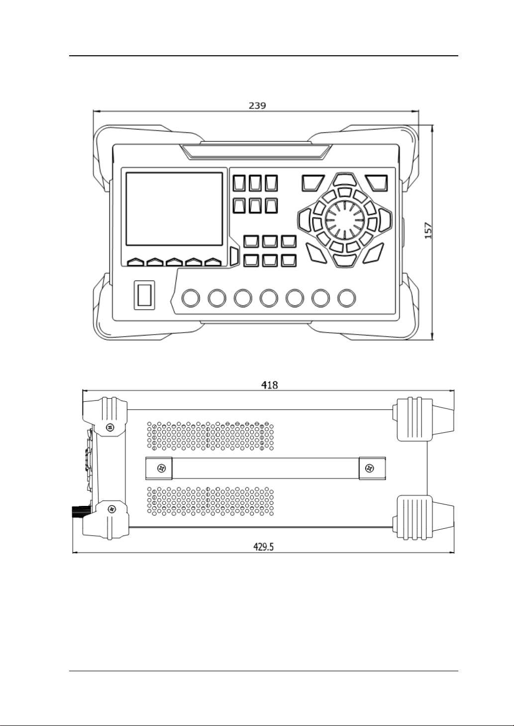
Appearance and Dimensions
Figure 1-1 Front View Unit: mm
Figure 1-2 Side View Unit: mm
DP800 User’s Guide 1-3
Page 22

RIGOL Chapter 1 Quick Start
1 2 3 4
11 10 9 8 7 6 5
Front Panel
This section introduces the front panel of DP800 serie s by takin g DP832 (as sh own in
the figure below) as an example. The differences of different models are introduced
separately.
Figure 1-3 DP832 Front Panel
1-4 DP800 User’s Guide
Page 23
Chapter 1 Quick Start RIGOL
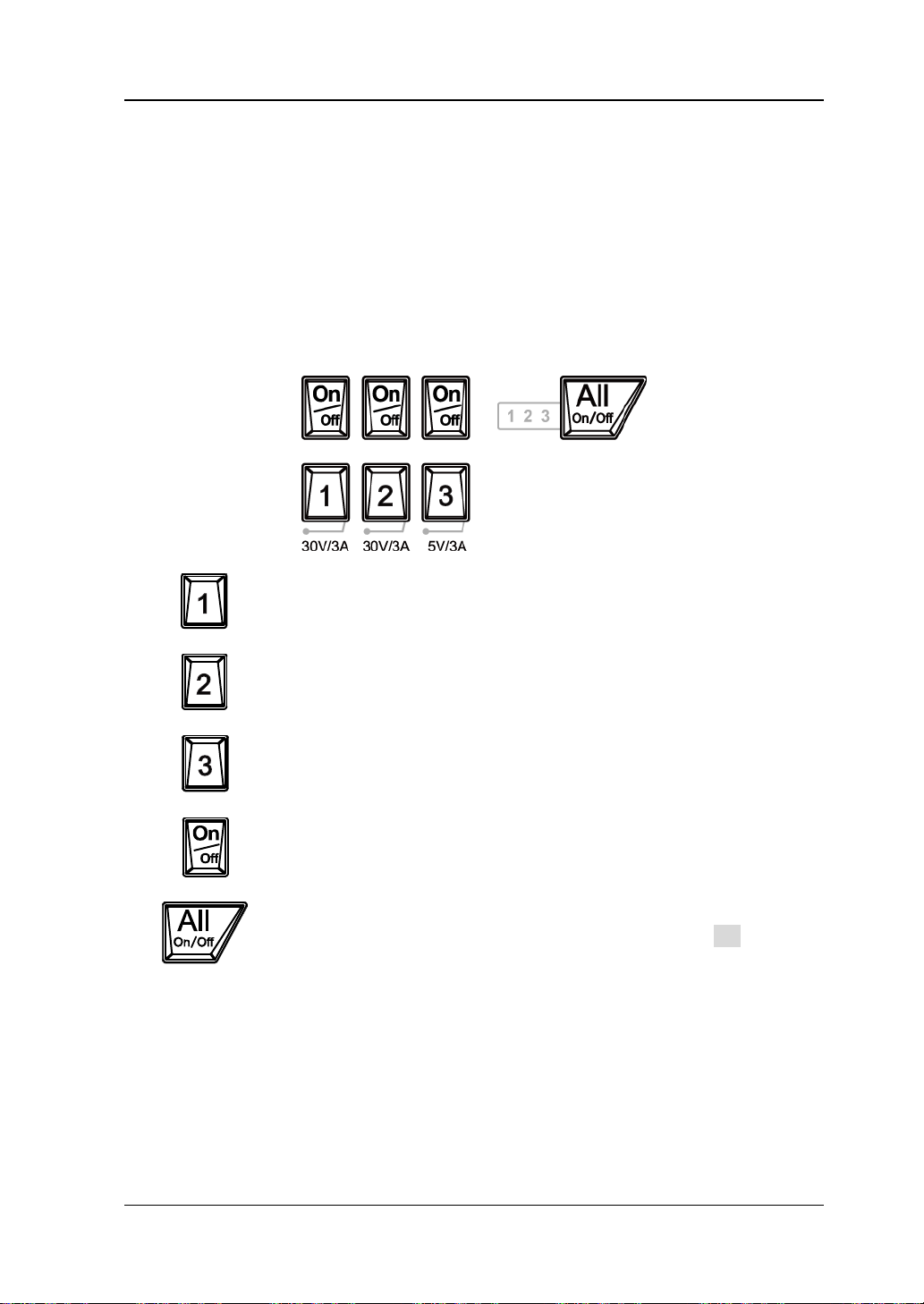
Press this key to select CH1 as the current channel and you can set
Press this key to select CH2 as the current channel and you can set
Press this key to select CH3 as the current channel and you can set
Press this key to enable or disable the output of the corresponding
Press this key and t h e prompt message asking whether to enable
the outputs of all the channels.
1. LCD
3.5 inches TFT display. It is used to display the system parameter setting,
system output state, menu items, prompt messages, etc.
2. Channel (Range) Selection and Output Switch
For the multi-channel model, the function of this part is channel selection and
output switch. For the single-channel model, the function of this part is range
selection and output switch.
Multi-channel models (take DP832 as an example):
the parameters of this channel, such as voltage, current and
overvoltage/overcurren t protection.
the parameters of this channel, such as voltage, current and
overvoltage/overcurren t protection.
the parameters of this channel, such as voltage, current and
overvoltage/overcurren t protection.
channel.
the outputs of all the channels will be dis played. Pres s OK to enable
the outputs of all the channels. Pressing this key again will disable
DP800 User’s Guide 1-5
Page 24
RIGOL Chapter 1 Quick Start
20V
10A
40V
5A
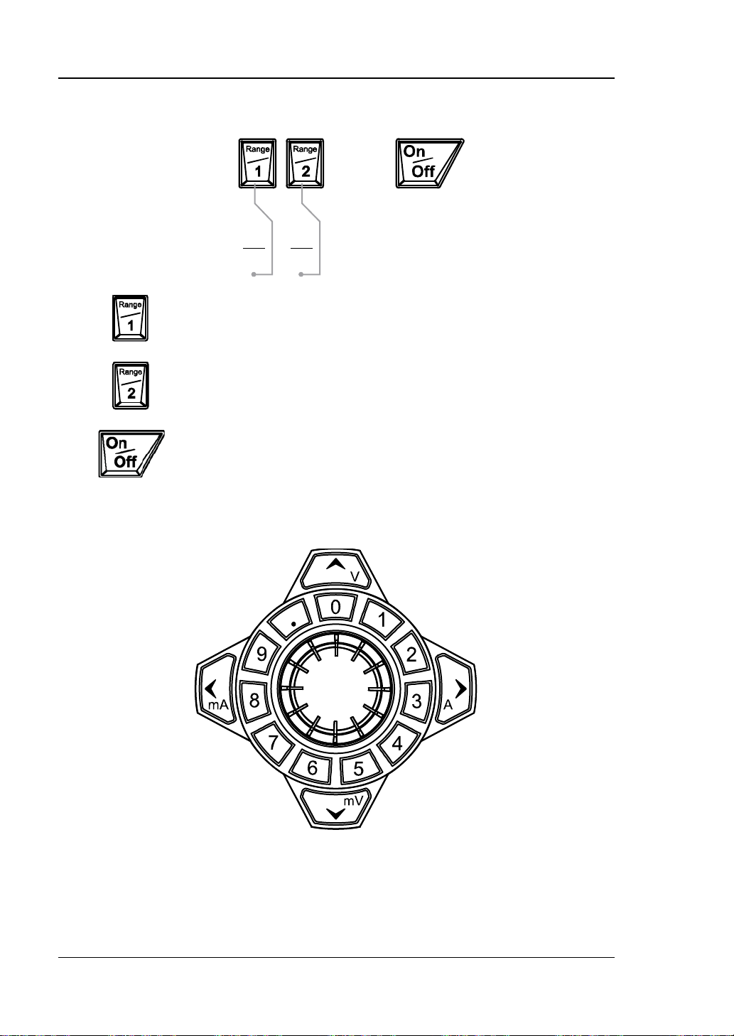
Press this key to select 20V/10A range as the current r an ge and
Press this key to select 40V/5A range as the current range and you
Press this key to enable or disable the output of the channel.
Single-channel model (DP811):
you can set the parameters of the channel, such as voltage,
current and overvoltage/overcurrent protection.
can set the parameters of the channel, such as voltage, current
and overvoltage/overcurrent protection.
3. Parameter In p ut Area
The parameter input area is as shown in the figure below. This area includes the
direction keys (unit selection keys), numeric keyboard and knob.
(1) Direction keys and unit selection keys
Direction keys: move the cursor. When setting parameters, use the
up/down direction key to increase or reduce the value at the cursor.
Unit selection keys: whe n usi ng the nume ric ke yboa rd t o i nput par ameter s,
1-6 DP800 User’s Guide
Page 25
Chapter 1 Quick Start RIGOL
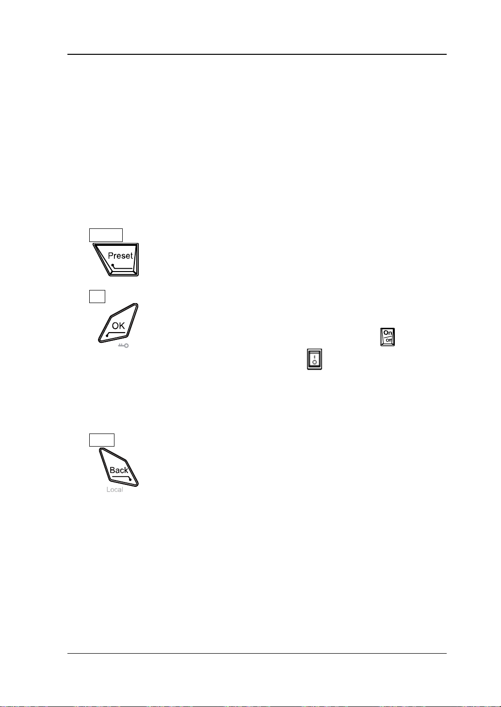
Restore all the settings of the instrument to default values or
Confirm the parameter setting.
Press and hold this key to lock the front pane l keys; at this point,
(2012) to unlock the front panel keys.
the keys are use d to enter the v oltage units (V and mV) or the current units
(A and mA).
(2) Numeric Keyboard
Ring-type numeric keyboard: include numbers 0-9 and the decimal point.
Press the corresponding key to directly input the number or decimal point.
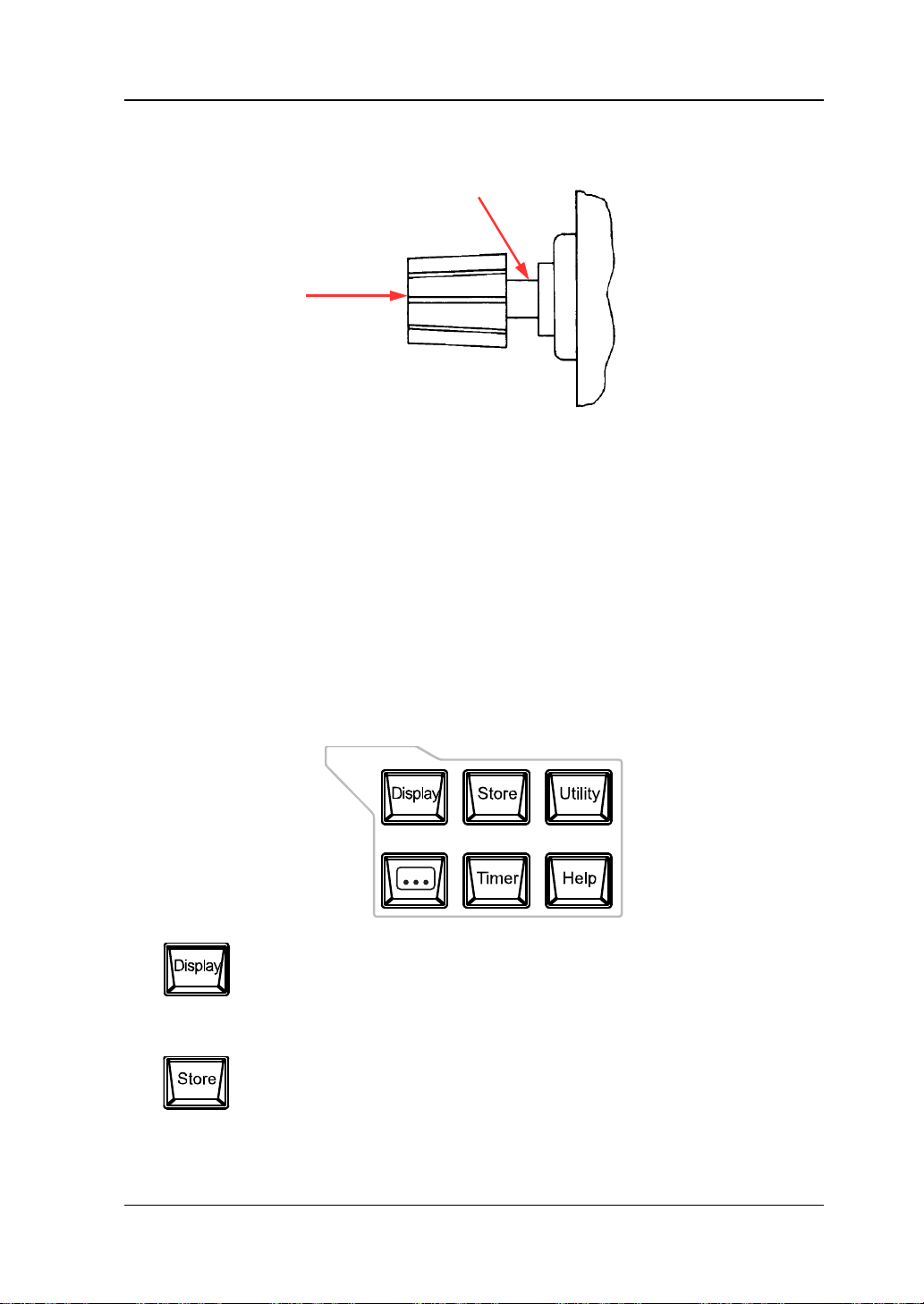
(3) Knob
When setting parameters, rotate the knob to increase or reduce the value
at the cursor.
When browsing the setting objects (timer parameters, delay parameters,
filename input, etc.), rotate the knob to quickly move the cursor.
4. Preset
recall the user-defined channel voltage/current configuration.
5. OK
the front panel keys (except the output on/off key o f each
channel and the power switch key ) are not available. When
the keyboard lock password is disabled, press and hold this key
again to unlock the front panel keys. When the keyboard lock
password is enabled, you need to input the correct password
6. Back
Delete the character currently before the cursor.
When the instrument is in rem ote mode, press t his key to return
to local mode.
DP800 User’s Guide 1-7
Page 26
RIGOL Chapter 1 Quick Start
8V/10A60V/1A
S S
Output
(1)
(3)
(1) (2)
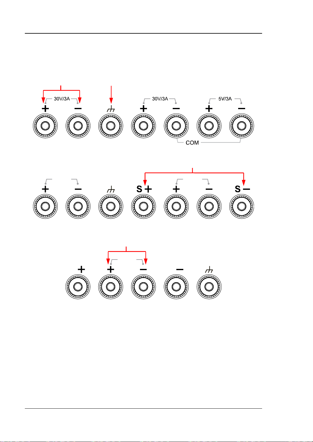
7. Output Terminals
The output terminals of different models of DP800 series are different.
DP832:
DP821:
DP811:
(1) Channel output terminals: used to output the voltage and current of the
channel.
(2) Ground terminal: this terminal is connected to the instrument chassis and
ground wire (the ground terminal of the power cord) and is in grounded
state.
(3) Sense terminals: used to detect the actual voltage at the load terminal so as
to compensate for the voltage drop c a u s ed by the load l e ad.
1-8 DP800 User’s Guide
Page 27
Chapter 1 Quick Start RIGOL
Press this key to enter the display parameter setting interface.
interface.
Press this key to enter the file store and recall interface. You can
and recall.
A
B
Connection methods of the output terminal:
Method 1:
Connect the test lead to A of the output terminal.
Method 2:
Rotate the outer nut of the output terminal counterclockwise and connect the
test lead to B of the output terminal; then, rotate the outer nut of the output
terminal clockwise. This connection method can eliminate the error caused by
the resistance of the output terminal.
Note: Connect the posit ive terminal of the test lea d w ith the (+) terminal of the
channel output and connect the negative terminal of the test lead with the (-)
terminal of the channel output.
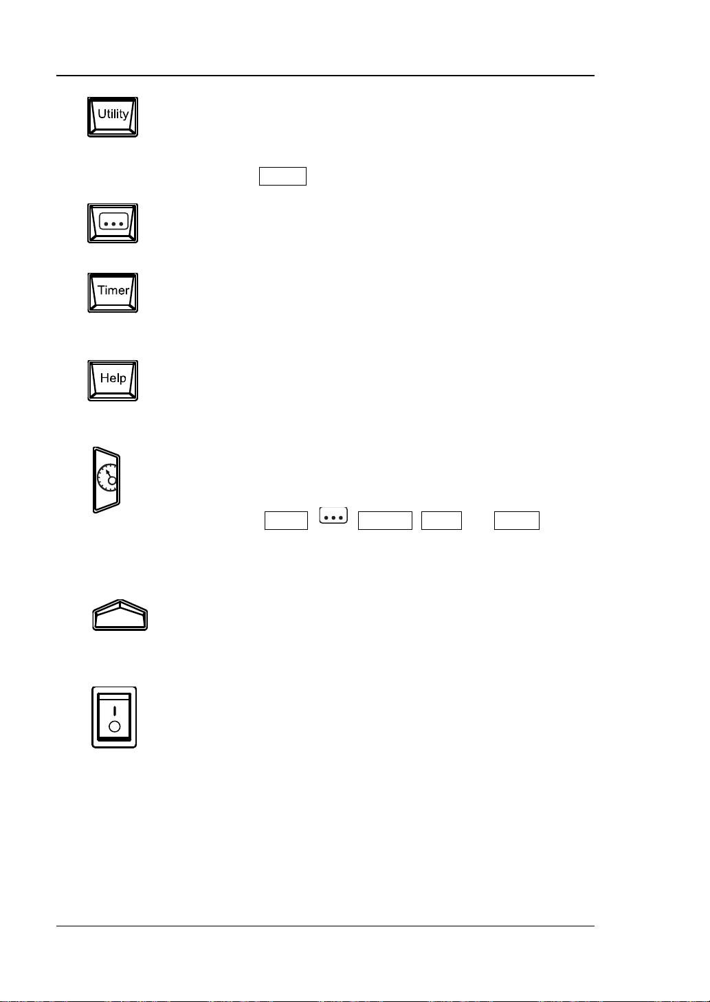
8. Function Menu Area
Users can set the brightness, contrast, RGB luminan ce, display
mode and display theme. Besides, you can a lso define the start-up
save, read, delete, copy and paste files. The file types available for
storage include state file, record file, timer f ile, delay file and
bitmap file. The instrument supports internal and external storage
DP800 User’s Guide 1-9
Page 28
RIGOL Chapter 1 Quick Start
Press this key to enter the system utility function setting interface.
configuration of Preset and install options.
Press this key to enter the advanced function setting interface.
trigger (option) parameters.
Press this key to enter the timer and delayer setting interface.
Press this key to open the built-in help system and press the
introductions, refer to "To Use the Built-in Help System".
interface.
The menu keys correspond to the menus above them
menu.
Users can set the remote interface parameters, system parameters
and print parameters. Besides, users can also calibrate the
instrument, view system information, define the recall
Users can set the recorder, analyzer (option), monitor (option) and
Users can set the timer and delayer parameters as well as enable
and disable the timer and delayer functions.
desired key to get the corresponding help information. F or detailed
9. Display Mode Switch/Return to the Main Interface
Switch between the current display mode and dial display mode.
Besides, when the instrument is in a function interface (any
interface under Timer,
press this key to exit the f unction interf ace and return to the main
10. Me nu Keys
respectively. Press any menu key to select the corresponding
11. Power Switch Key
Turn on or off the instrument.
, Display, Store and Utility),
1-10 DP800 User’s Guide
Page 29
Chapter 1 Quick Start RIGOL
T6
.3A
T
3.
1
5A
AC 1
00V
A
C 1
1
5V
AC
23
0V
500V
A
O
pt
. O
p
t.
Op
t
.
T6.
3A
T3.15A
AC 100V
AC 115V
AC 230V
500VA
Opt. Opt.
Opt.
S
S+
1 2 3 4 5 6
10 9 8 7
11
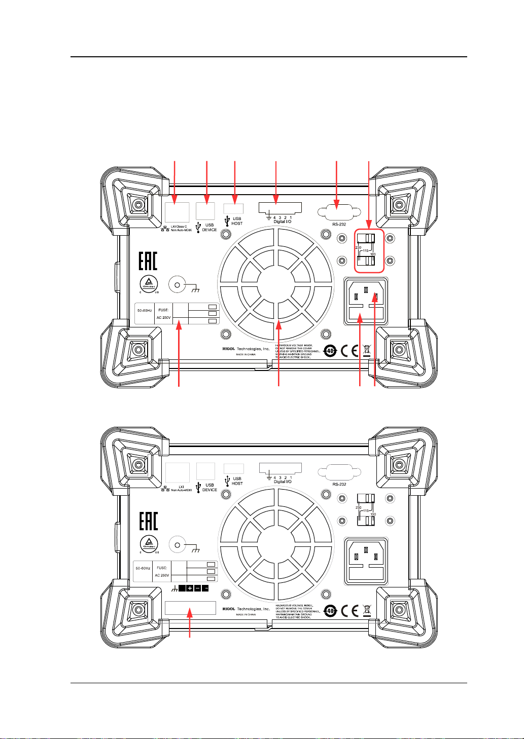
Rear Panel
This section introduces the rear panel of DP800 series by taking DP832 and DP811
(as shown in the figures below) as examples. The introduction of each part is as
shown in Table 1-1.
Figure 1-4 DP832 Rear Panel
Figure 1-5 DP811 Rear Panel
DP800 User’s Guide 1-11
Page 30
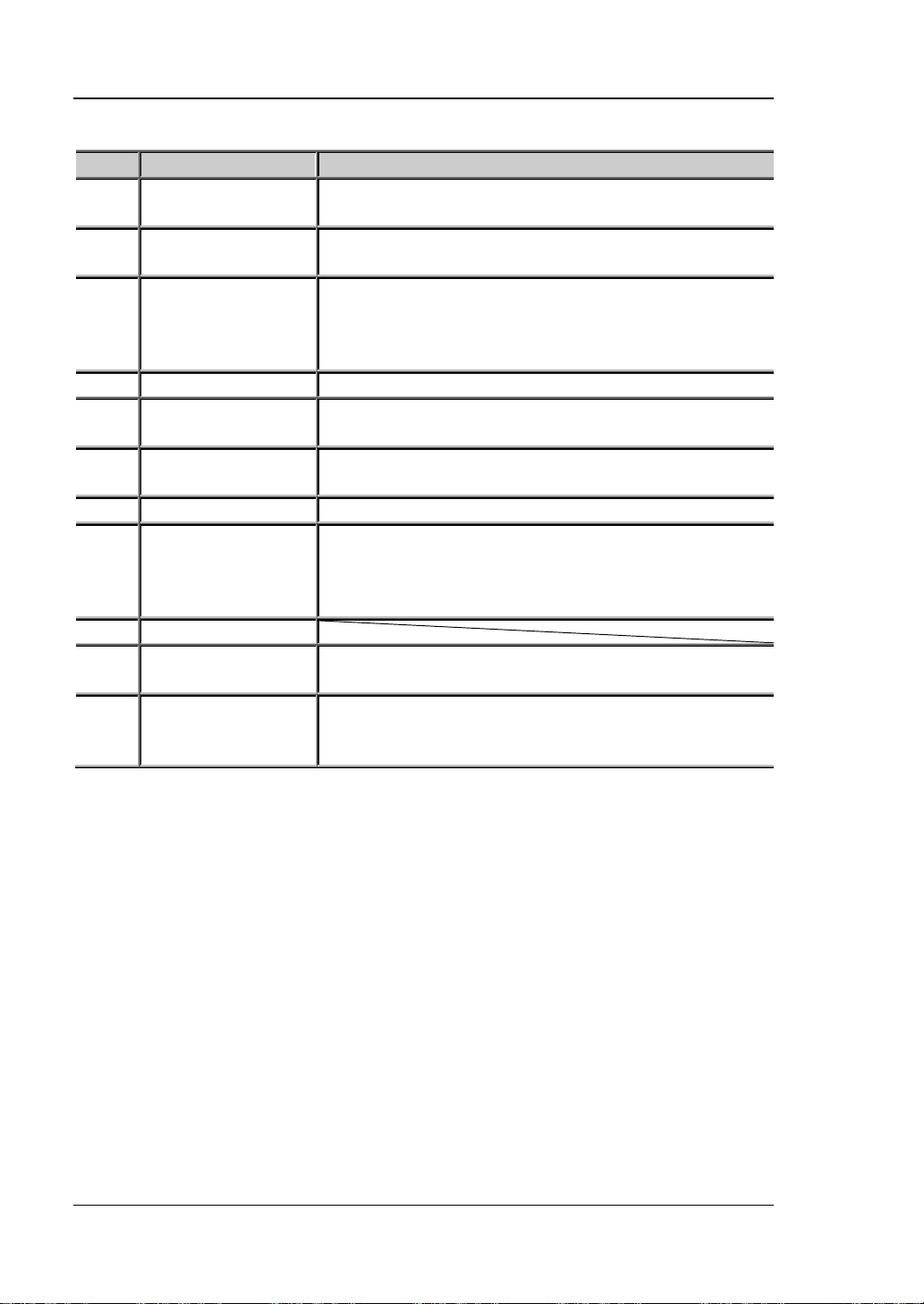
RIGOL Chapter 1 Quick Start
No.
Name
Explanation
LAN Interface
(option)
The instrument is connected to the local network via
RJ45 interface
Connect the instrument (as "slave" device) to
Connect the instrument (as "host" device) to external
USB-GPIB interface converter (option)
4
Digital I/O (option)
Digital I/O interface
RS232 Interface
(option)
Select the specification of the input voltage (100, 115
or 230; please refer to Table 1-2)
7
Power Socket
AC power input interface.
The specification of the fuse is related to the
panel of the instrument or refer to Table 1-3).
9
Fan
Input Power
Requirement
Corresponding relations of the AC input power
frequency, voltage and the specification of the fuse.
DP811 provides this interface. The function of this
Terminals" at the front panel.
Table 1-1 DP800 rear panel explanation
1
2 USB DEVICE
3 USB HOST
5
6 Voltage Selector
8 Fuse
10
11 Output Interface
external USB device (such as PC)
USB device (such as USB storage device);
extend a GPIB interface for the power supply using
Serial communication interface
instrument model and actual input voltage (please
refer to the "Input Power Requirements" at the rear
interface is the same as that of the "Output
Note: The "Output Terminals" at the front panel and "Output Interface" at the rear
panel cannot be used for output at the same time. You can only select one of them
for output at each time (wherein, the output terminals at the front panel provide
higher output accuracy).
1-12 DP800 User’s Guide
Page 31
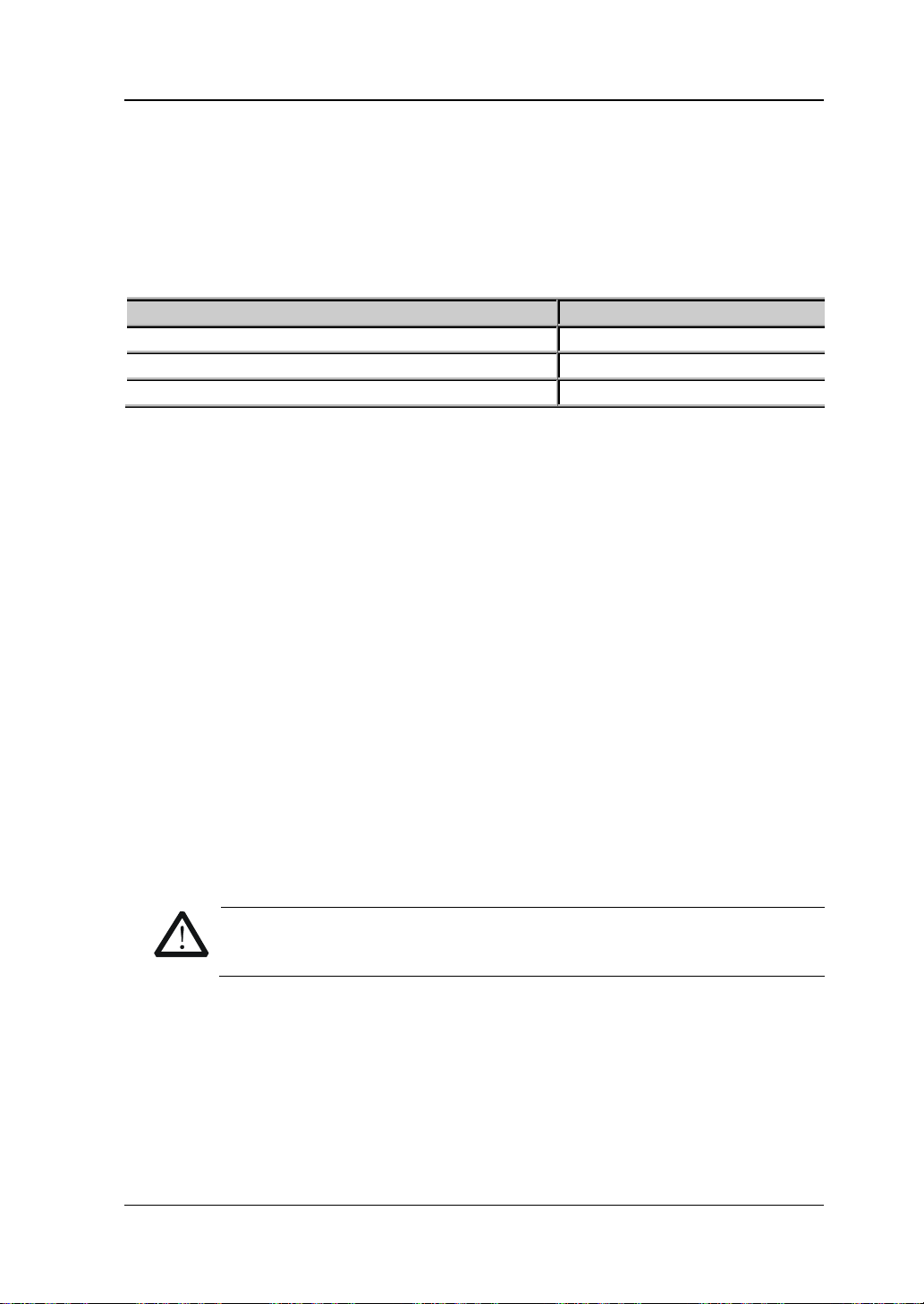
Chapter 1 Quick Start RIGOL
AC Input Power
Voltage Sele ctor Settin g
100Vac±10%, 50Hz to 60Hz
100
115Vac±10%, 50Hz to 60Hz
115
230Vac±10% (250Vac maximum ), 50Hz to 60Hz
230
WARNING
grounded.
To Connect to Power
DP800 series power supply supports various AC power supply inputs. The voltage
selector setting at the rear panel differs when the input power connected is different,
as shown in the table below.
Table 1-2 AC input power specifications (including voltage selector settings)
Please connect the power following the steps below.
1. Check the input power
Make sure that the AC power to be connected to the instrument fulfills the
requirements in Table 1-2.
2. Check the voltage selector at the rear panel
Make sure that the v oltage selector set ting (110, 115 or 230) at the rear panel of
the instrument matches the actual input voltage (for the matching relations refe r
to Table 1-2).
3. Check the fuse
When the instrument leav es f actory, the specified fuse is installed. Please che ck
whether the fuse matches the actual input voltage according to the "Input
Power R e quirements" at the rear panel of the instrument or Table 1-3.
4. Connect the AC power
Connect the instrument to AC power supply using the power cord provided in
the accessories.
To avoid electric shock, make sure that the instrument is correctly
DP800 User’s Guide 1-13
Page 32
RIGOL Chapter 1 Quick Start
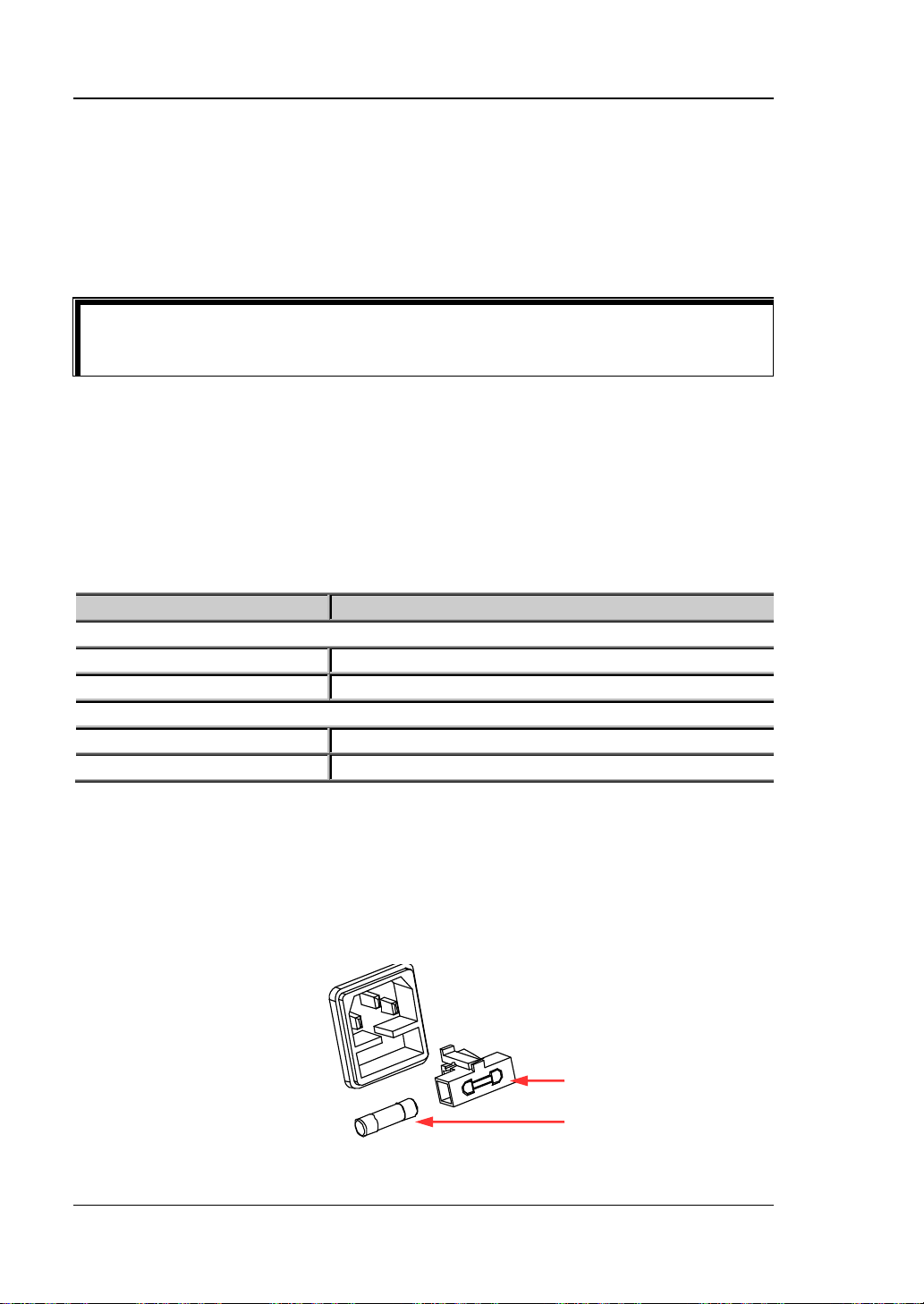
Tip
Input Voltage
Fuse Specification
DP832/DP811
100Vac/115Vac
T6.3A
230Vac
T3.15A
DP831/DP821
100Vac/115Vac
T5A
230Vac
T2.5A
Fuse Seat
Fuse
Power-on Inspection
Press the power switch at the front panel, the instrument starts and executes
self-test. If the instrument passes the self-test, the welcome interface will be
displayed; otherwise, the corresponding self-test failure information (including the
top board, bottom boa rd, fan and tem pe rature) will be di s pl ayed.
When powering on the instrument after powering off it, make sure that the time
interval between the two operations is greater than 5s.
To Replace the Fuse
The fuse specification is related t o the inst rument model and actual input voltage, a s
shown in the table below. You can also refer to the "Input Power Requirements" at
the rear panel of the instrument.
Table 1-3 Fuse specifications
To replace the fuse, follow the steps below.
1. Turn off the instrument and remove the power cord.
2. Insert a small straight sc rewdrive r into th e slot at the pow er socke t and pri ze out
the fuse seat gently.
1-14 DP800 User’s Guide
Page 33

Chapter 1 Quick Start RIGOL
WARNING
to this specification before connecting to power.
3. If needed, adjust the power volta ge selector manually to select the voltage s cale
(please refer to Table 1-4) that matches the actual input voltage.
4. Take out the fuse and replace it with a specified one (please refer to the "Input
Power R e quirements" at the rear panel of the instrument or Table 1-3).
5. Re-insert the fuse seat into the power socket (pay attention to the direction).
To avoid personal injuries, cut off the power supply before replacing the
fuse; to avoid elect ric shock or fire, select the power supply specification
that matches the actual input voltage and replace a fuse corresponding
DP800 User’s Guide 1-15
Page 34

RIGOL Chapter 1 Quick Start
1 2 3 4 5
6
User Interface
DP800 series po wer su pply provide s th ree kin ds of displa y mo des (no rmal, wav ef orm
and dial). The default is normal. You can press Display Disp Mode to select
different display mode. This section introduces the user interface layout under the
normal display mode (as shown in the figure below and
7
8
9
10
Table 1-4 on the next page).
11
Figure 1-6 User Interface (Normal Di splay Mode)
1-16 DP800 User’s Guide
Page 35

Chapter 1 Quick Start RIGOL
No.
Explanation
1
Channel number
2
Channel output voltage/current
3
Channel output status
4
Channel output mode
5
Status bar. Display the system status labels.
: the instrument is in remote mode.
6
Actual output voltage
7
Actual output current
8
Actual output power
9
Voltage and current setting values
10
Overvoltag e and over current protecti on setting values
11
Menu bar
Tip
panel to quickly switch between the current display mode and dial displa y mo de.
Table 1-4 User Interface Explanation
: over-temperature protection is enabled
: the front panel is locked.
: the network is connected.
: USB device is recognized.
: the beeper is enabled.
: the beeper is disabled.
When the current display mode is "Normal" or "Waveform", press at the front
DP800 User’s Guide 1-17
Page 36

RIGOL Chapter 1 Quick Start
To Use the Built-in Help System
The built-in help s ystem provides help inf ormation f or any f ront panel k ey (except the
parameter input area) and menu keys for users to quickly obtain the function
prompts of the function keys or menus.
Obtain the help information of any key or menu key
Press Help to illuminate it and press the desired key or menu key to get the
corresponding help information; at the same time, the backlight of Help goes off.
Press to ex it the help system.
Built-in help interface
Press Help to illuminate it and press Help again to open the built-in help interface.
Use the up/d own direction key or knob to select the desired help topic and press
View to view the corresponding help information.
The help topics include:
1. View the last displayed message.
2. View error queue of the remote comm ands .
3. Get the help information of a key.
4. Storage manageme nt.
5. Abbreviations list.
6. Series-parallel Help.
7. Get technical support from RIGOL.
1-18 DP800 User’s Guide
Page 37
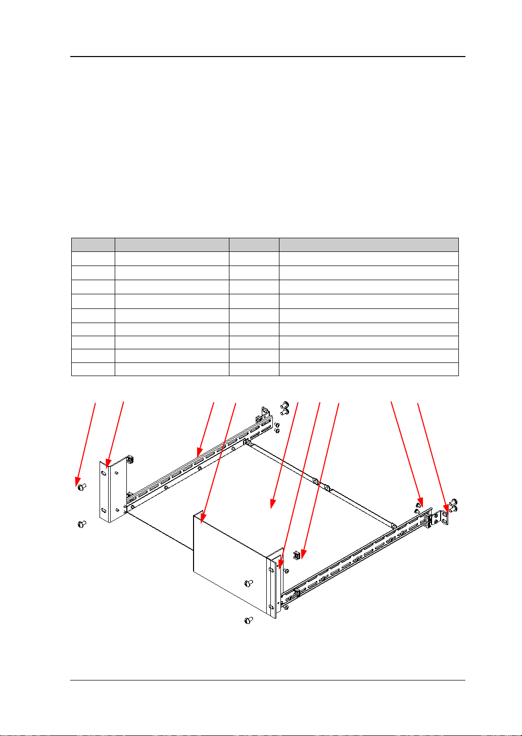
Chapter 1 Quick Start RIGOL
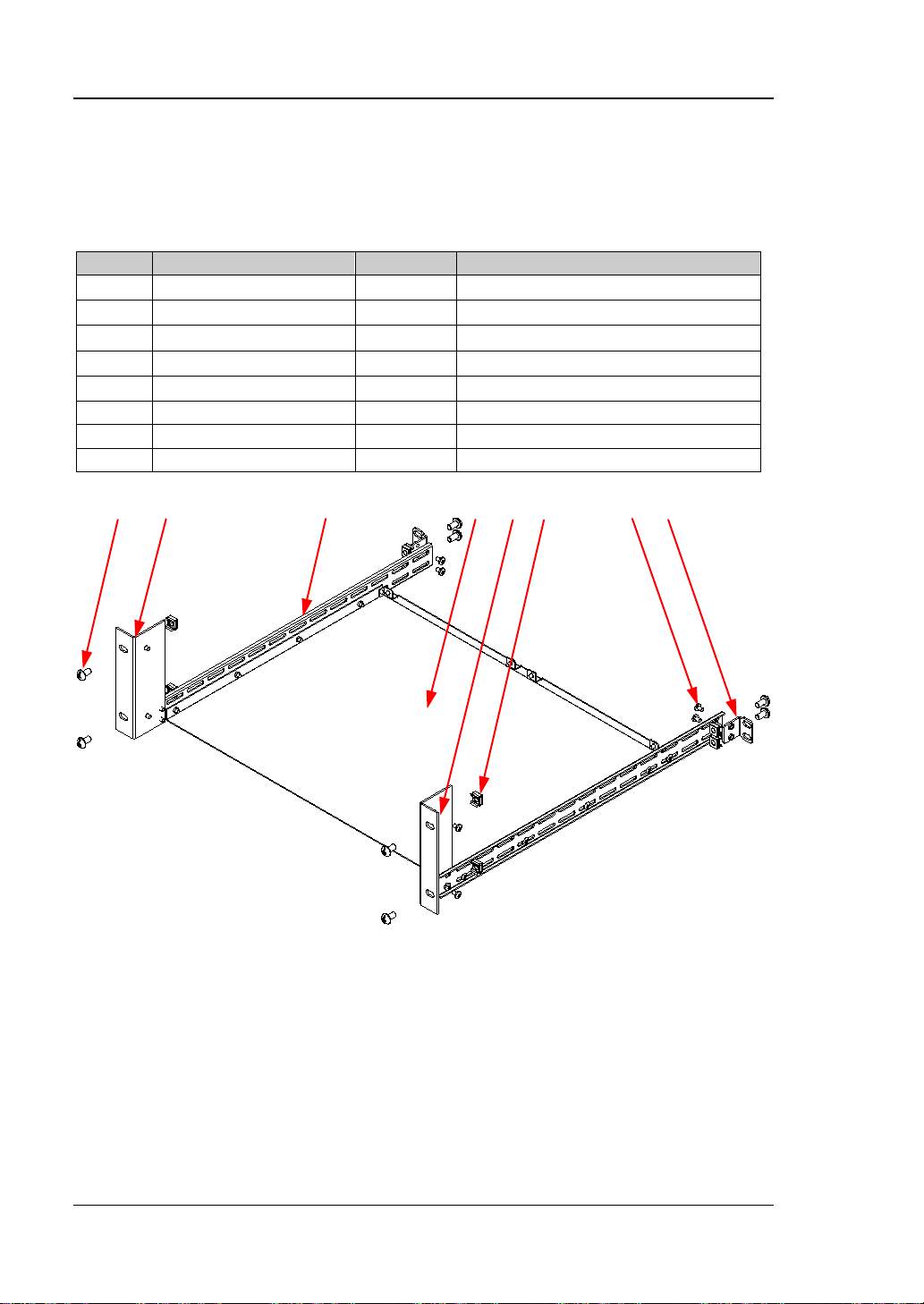
No.
Name
Qty.
Description
Rack Support Shelf
1
②
Front Filler Panel
1
Rack Left Fixing Part
1
Rack Right Fixing Part
1
⑤
Rack Rail
2
⑥
Side B e am Fixing Part
2
M4 Screw
26
M4×6 Phil-Slot Pan Head Screw
M6 Screw
8
M6×16 Phil-Slot Pan Head Screw
M6 Screw
8
M6×5 Lock Blade Square Nut
⑧ ③ ⑤ ② ① ④ ⑨ ⑦ ⑥
To Rack Mount the Instrument
If you want to i nstall the inst rument int o a standar d 19 in ch ma chine cabinet, please
order the rack mount kit (RM-1-DP800 or RM-2-DP8 00; the forme r is used to i nstall a
single instrument and the latter is used to install two instruments) and install the
instrument according to the instructions below.
To Install a Single Instrume nt
Part List
Table 1-5 Rack mount kit (RM-1-DP800) part list
①
③
④
⑦
⑧
⑨
(a)
DP800 User’s Guide 1-19
Page 38

RIGOL Chapter 1 Quick Start
⑦ ⑧ ⑨
(b)
Figure 1-7 Rack Mount Kit (RM-1-DP800) Parts
Installation Tool
PH2 Phillips screwdriver is recommended.
Installation Space
The machine cabinet should fulf ill the following requirements.
It should be a standard 19 inch machine cabinet;
At least 4U (177.8 mm) space should be provided by the machine cabinet ;
The depth inside the machine cabinet should not be less than 463.75mm.
The rack-mounted instrument is as shown in the figure below.
1-20 DP800 User’s Guide
Page 39
Chapter 1 Quick Start RIGOL
CAUTION
of the instrument onto the rack.
Installation Procedures
Only authorized personnel can perform the installation. Improper
operation might cause damage to the instrument or incorrect installation
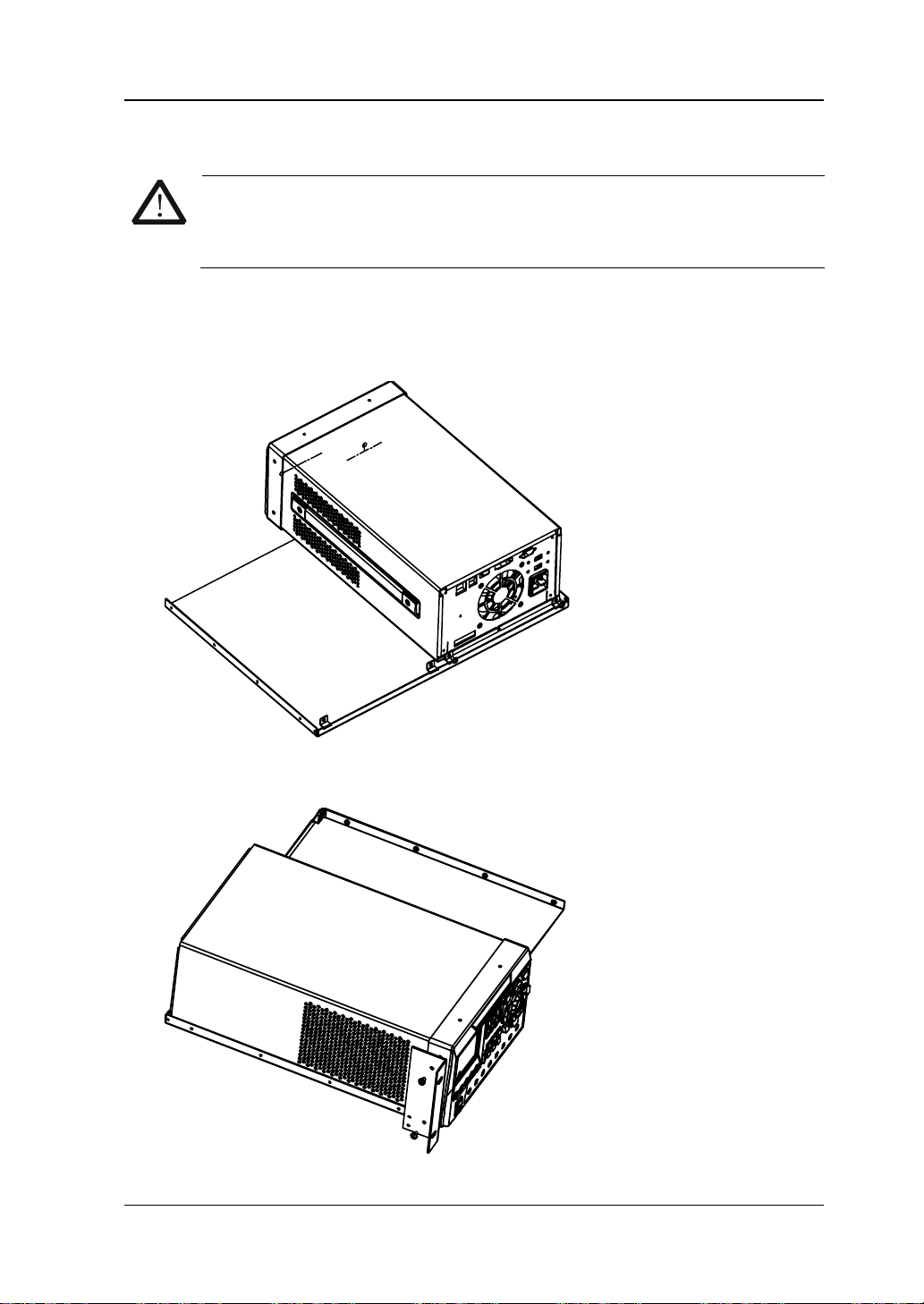
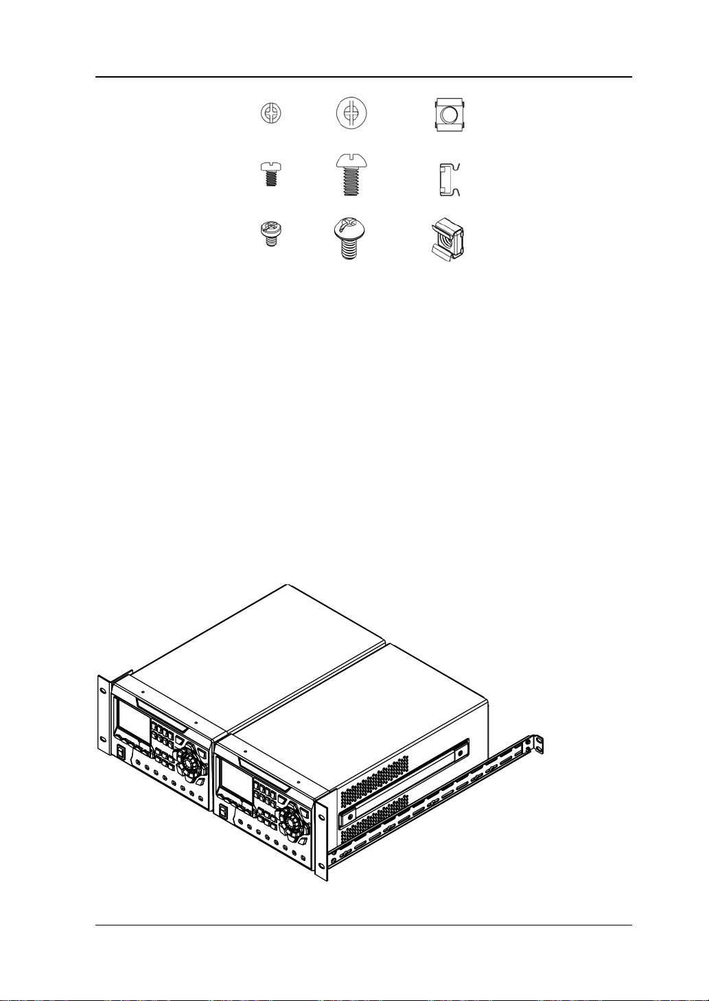
1. Remo ve t he f our rubbe r bumpers on the front and rear panels of the inst rument
respectively.
2. Fix the instrument onto the rack support shelf using two M4 screws.
3. Fix the left fixing part to the left side of the front panel of the instrument using
two M4 screws.
DP800 User’s Guide 1-21
Page 40

RIGOL Chapter 1 Quick Start
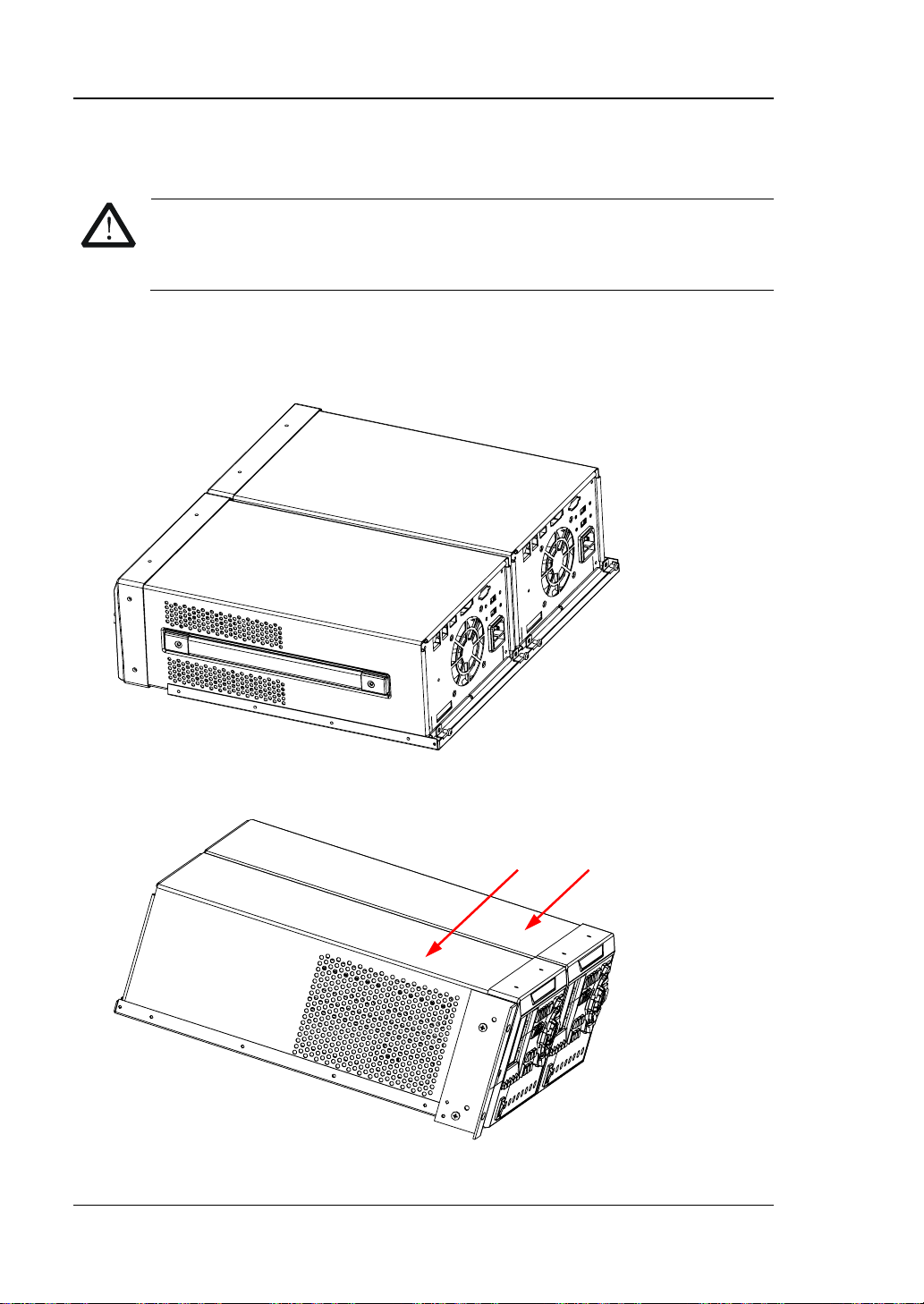
4. Fix the front f iller panel to the right side of the front panel of the instrument
using two M4 screws.
5. Fix the right fixing part to the right side of the front filler panel using two M4
screws.
1-22 DP800 User’s Guide
Page 41
Chapter 1 Quick Start RIGOL
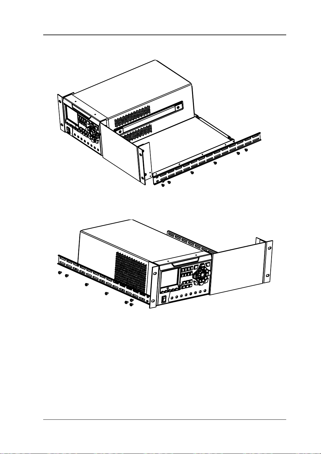
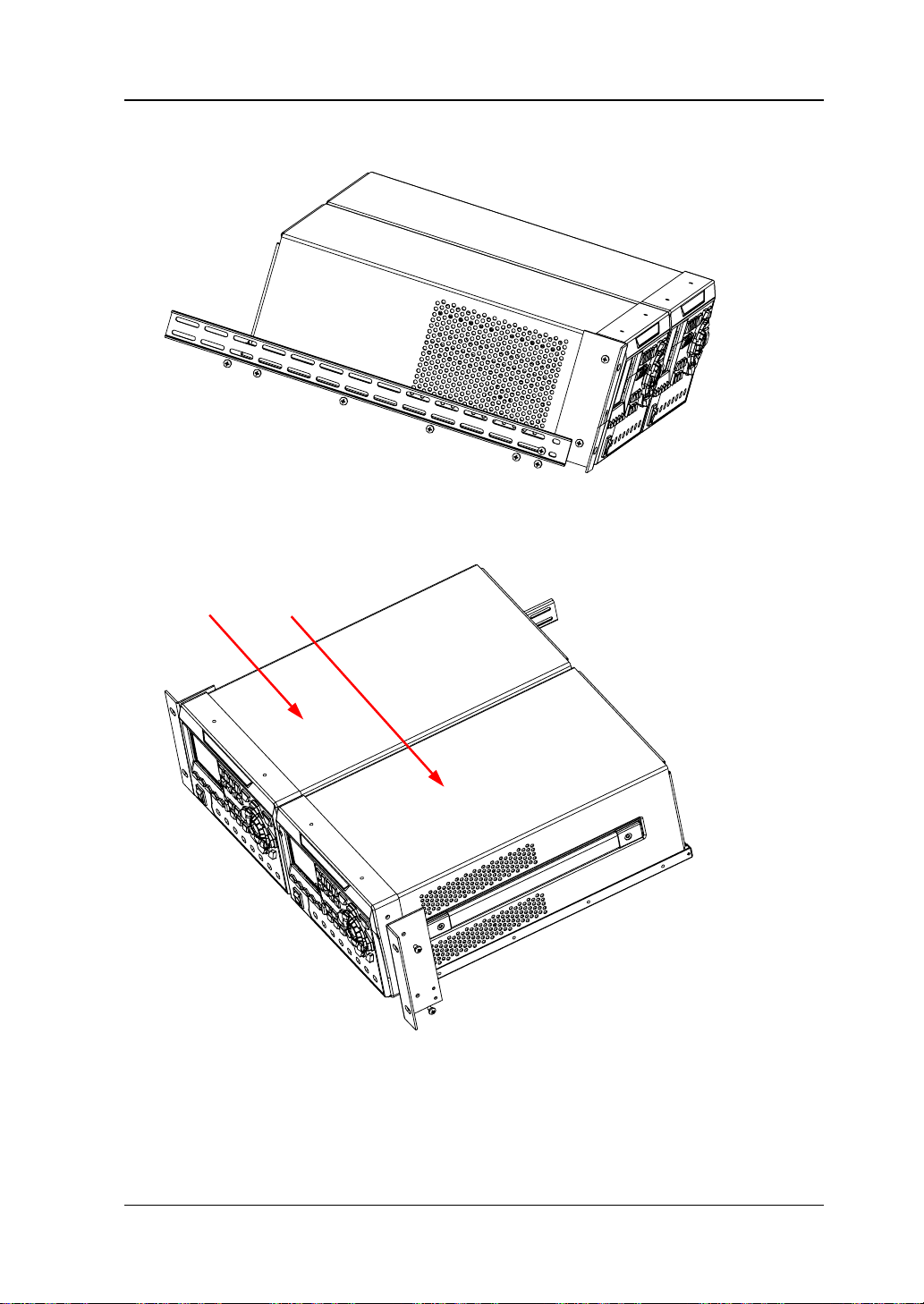
6. Fix a rack rail to the right side of the rack support shelf using seven M4 screws.
7. Fix the other rack rail to th e left side of the rack support shelf using seven M4
screws.
DP800 User’s Guide 1-23
Page 42
RIGOL Chapter 1 Quick Start
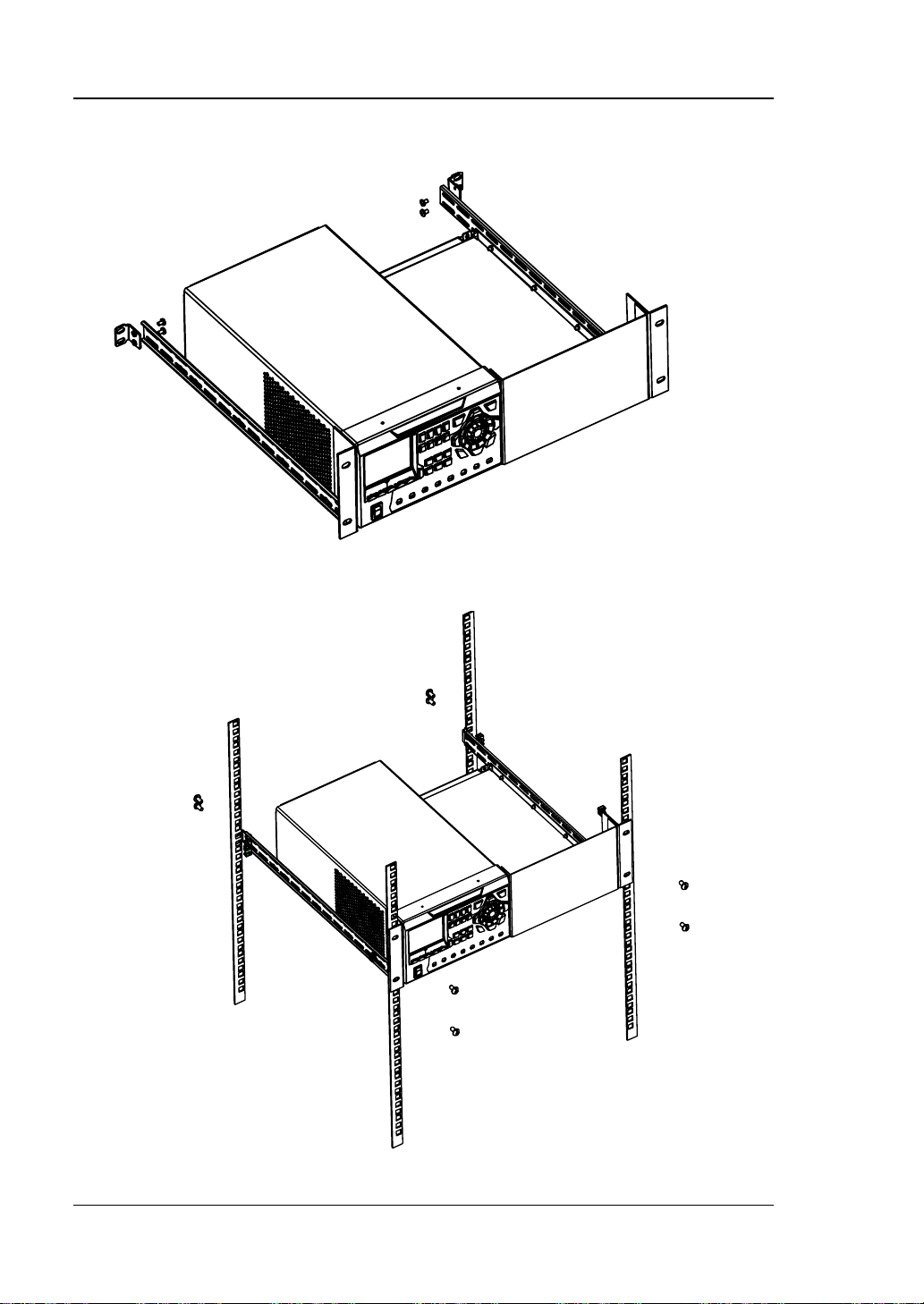
8. Fix the t wo side bea m fixing pa rts t o the en d pa rts of t he le ft a nd right r ack r ails
using four M4 screws respectively.
9. Install the rack mounted with the instrument into a standard 19 inch machine
cabinet using eight M6 screws and eight M6 nuts.
1-24 DP800 User’s Guide
Page 43
Chapter 1 Quick Start RIGOL
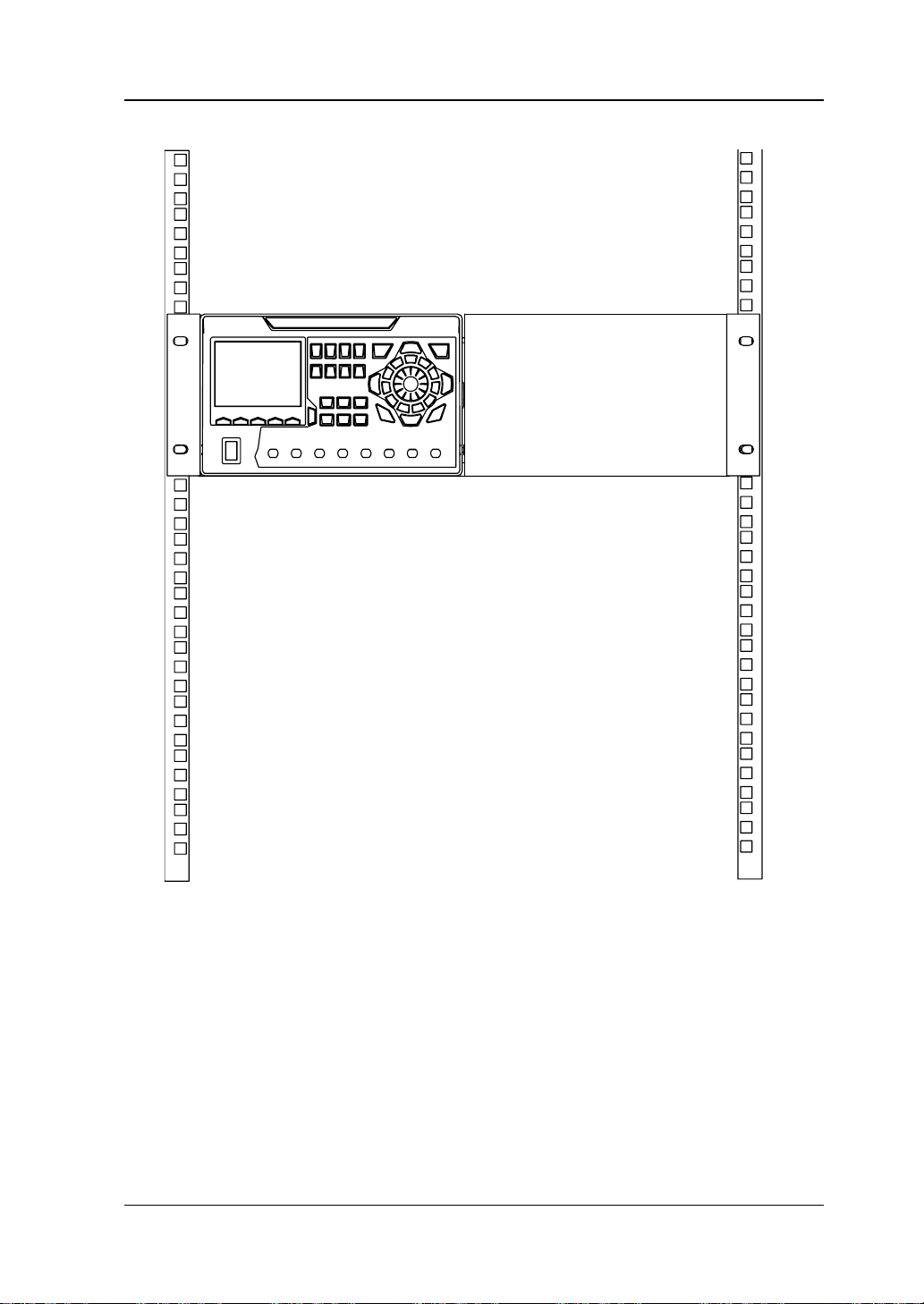
10. At this point, the diagram of the instrument is as shown in the figure below.
DP800 User’s Guide 1-25
Page 44
RIGOL Chapter 1 Quick Start
No.
Name
Qty.
Description
Rack Support Shelf
1
Left Fixing Part
1
③
Right Fixing Part
1
Rack Rail
2
Side B e am Fixing Part
2
M4 Screw
26
M4×6 Phil-Slot Pan Head Screw
⑦
M6 Screw
8
M6×16 Phil-Slot Pan Head Screw
⑧
M6 Nut
8
M6×5 Lock Blade Square Nut
⑦ ② ④ ① ③ ⑧ ⑥ ⑤
To Install Two Instruments
Part List
Table 1-6 Rack mount kit (RM-2-DP800) part list
①
②
④
⑤
⑥
(a)
1-26 DP800 User’s Guide
Page 45
Chapter 1 Quick Start RIGOL
⑥ ⑦ ⑧
(b)
Figure 1-8 Rack Mount Kit (RM-2-DP800) Parts
Installation Tool
PH2 Phillips screwdriver is recommended.
Installation Space
The machine cabinet should fulf ill the following requirements.
It should be a standard 19 inch machine cabinet;
At least 4U (177.8 mm) space should be provided by the machine cabinet ;
The depth inside the machine cabinet should not be less than 463.75mm.
The rack-mounted instruments are as shown in the f ig ure below.
DP800 User’s Guide 1-27
Page 46
RIGOL Chapter 1 Quick Start
CAUTION
of the instrument onto the rack.
Instrument A Instrument B
Installation Procedures
Only authorized personnel can perform the installation. Incorrect
operation might cause damage to the instrument or incorrect installation
1. Remove the four rubber bumpers on the front and rear panels respectively.
2. Fix the two instruments onto the rack support shelf using two M4 screws
respectively.
3. Fix the left fixing part to the left side of the front panel of instrument A using tw o
M4 screws.
1-28 DP800 User’s Guide
Page 47
Chapter 1 Quick Start RIGOL
Instrument A Instrument B
4. Fix a rack rail to the left side of the rack support shelf using seven M4 screws.
5. Fix the right fixing part to the right side of the front panel of inst rument B using
two M4 scre ws.
DP800 User’s Guide 1-29
Page 48

RIGOL Chapter 1 Quick Start
6. Fix the other rack rail to th e right side of th e rack support shelf using seven M4
screws.
7. Fix the two side beam fixing parts to the end parts o f the left and right rack rails
using four M4 screws respectively.
1-30 DP800 User’s Guide
Page 49

Chapter 1 Quick Start RIGOL
8. Install the rack mounted with the instruments into a standard 19 inch machine
cabinet using eight M6 screws and eight M6 nuts.
DP800 User’s Guide 1-31
Page 50

RIGOL Chapter 1 Quick Start
9. The rack -mounted instruments are as shown in the figure below.
1-32 DP800 User’s Guide
Page 51

Chapter 2 Front Panel Operations RIGOL
Chapter 2 Front Panel Operations
The contents of this chapter are as follows:
Constant Voltage Output
Constant Current Output
Power Supply Series and Parallel Connections
Track Function
Sense Working Mo de
Timer and Delayer
Advanced Functions
Display Setting
Store and Recall
Utility
Key Locking
DP800 User’s Guide 2-1
Page 52

RIGOL Chapter 2 Front Panel Operations
CAUTION
the instrument and the devices connected to the instrument.
Constant Voltage Output
DP800 series power supply provides three ou tput modes : consta nt voltag e output
(CV), constant current output (CC) and critical mode (UR). In CV mode, the output
voltage equals the volta ge set ting v alue a nd the output current is deter mined by th e
load; in CC mode, the output current equals the current se tting v alue an d the outpu t
voltage is determined by the load; UR is the critical mode between CV and CC. This
section introduces the operation method in constant v olt age output mo de.
Operation Method:
1. Connect the channel output terminals
As shown in the figure below, connect the load with the channel output
terminals of the corresponding channel at the front panel.
Pay attention to the polarity when connecting them to avoid damaging
2. Tu r n on the power switc h to start th e instrum en t.
3. Select the channel
Select the proper output channel according to the d e sired output voltage. Press
the correspon di ng channel selection key; at this point, this channel, its channel
number, output state and output mode are high-lighted on the screen.
4. Set the voltage
Method 1
Press Voltage and use the left/right direction key to move the cursor; then,
rotate the knob to quickly set the volta ge and the default unit is V. After selecting
the digit to be set, you can also use the up/down direction key to modify the
value of the corresponding digit. The default unit is V.
Method 2
Press Voltage, use the numeric keyboard to directly input the desired voltage
value and press V or mV or press the unit selection key ( or ) to
2-2 DP800 User’s Guide
Page 53

Chapter 2 Front Panel Operations RIGOL
select the desired unit. Besides, y ou can also press OK to select the default u nit
(V). During the input, you can press Back to delete the character currently
before the cursor or press Cancel to cancel the input.
Method 3
If Current is currently selected, you can also use the numeric keyboard to
directly input the desired voltage value; and then press the unit selection key
(
or ) to select the desired voltage unit. During the input, you can
press Back to delete the character currently before the cursor or press Cancel
to cancel the input.
5. Set the current
Method 1
Press Current and use the left/right direction key to move the cursor; then,
rotate the knob to quickly set the current and the default unit is A. After
selecting the digit to be set, you can also use the up/down direction key to
modify the value of the corresponding digit. The default unit is A.
Method 2
Press Current, use the numeric keyboard to directly input the desired current
value and press A or mA or press the unit selection k ey ( or ) to select the
desired unit. Besides, you can also press OK to select the default unit (A).
During the input, you can press Back to delete the character currently before
the cursor or press Cancel to cancel the input.
Method 3
If Voltage is currently selected, you can also use the numeric keyboard to
directly input the desired current value; and then press the unit selection key
or ) to select the desired current unit. During the input, you can
(
press Back to delete the character currently before the cursor or press Cancel
to cancel the input.
6. Set the overcurrent protection
Press OCP to set a proper overcurrent protection value (for the sett ing metho d,
refer to "
Set the current"). Then, enable the overcurrent protection function
(you can enable or disable the OCP function by pres s ing OCP) and the output
will be turned off automatically when the actual output current is greater than
the overcurrent protection value.
7. Turn on the output
Turn on the output of t he corresponding channel and the actual output voltag e,
output current, output power as well as the output mode (CV) are high-lighted
in the user interface.
DP800 User’s Guide 2-3
Page 54

RIGOL Chapter 2 Front Panel Operations
Warning
output terminals are correctly connected.
CAUTION
otherwise, "The fan stops, stop the output!" will be displayed.
Ouput Interface at
Connecting
To avoid electric shock, please turn on the output switch after the
When the fan stops, the channel switch can not be turned on;
8. Check the output mode
In constant voltage output mode, the output mode displayed should be "CV"; if
"CC" is displayed, you can increase the current setting value properly and the
power supply will switch to CV mode automatically.
In addition, DP811 provides an output interface at the rear panel for constant voltage
output. As shown i n t he figure below, connect the load and the output interface at
the rear panel via the connecting terminal.
the Rear Panel
Terminal
Connecting Procedures:
1. Connect the load to the corresponding positions on the connecting terminal
correctly. Pay attention to the polarity when making connections.
2. Insert the connecting terminal into the output interface at the rear panel of the
instrument. Pay attent ion to the corresp on ding relations of the connecting
terminal and the output interface.
Note: The output terminals at the front panel and the output interface at the rear
panel cannot be used for output at the same time. You can only select one of them
for output at each time (wherein, the output terminals at the front panel provide
2-4 DP800 User’s Guide
Page 55

Chapter 2 Front Panel Operations RIGOL
Tip
value, the power supply will swit ch to CC output mode aut omatically. At this point,
the output current equals the current sett ing value a nd the output v oltage reduces
proportionally.
higher output accuracy).
In CV output mode, when the load current is greater than the current setting
DP800 User’s Guide 2-5
Page 56

RIGOL Chapter 2 Front Panel Operations
Warning
terminals are correctly connected.
Constant Current Output
In constant current output mode, the output current equals the c urrent set ting v alue
and the output voltage is determined by the load. This section introduces the
operation method in constant current output mo de.
Operation Method:
1. Connect the channel output terminals
Connect the load with the channel output terminals of the corresponding
channel at the front panel by referring to "Connect the channel output
terminals" in "Constant Volta ge Out put".
2. Tu r n on the power switc h to start th e instrum en t.
3. Select the channel
Select the proper output channel a cco rding to the desired output current. Pres s
the corresponding channel selection key; at this point, this channel, its channel
number, output state and output mode are high-lighted on the screen.
4. Set the voltage
Press Voltage to set the desired voltage according to "Set the voltage" in
"Constant Voltage Out put".
5. Set the current
Press Current to set the desired current according to "Set the current" in
"Constant Voltage Out put".
6. Set the overvoltage protection
Press OVP to set a proper overvoltage prot ecti on v alu e (for the setting method,
refer to "
overvoltage protection fun ction (you can enable or disable the OVP function by
pressing OVP) and the output will be turned off automatically when the actual
output voltage is greater than the overvoltage protection value.
7. Turn on the output
Turn on the output of t he corresponding channel and the a ctual output volta ge,
output current, output power as well as the output mode (CC) are high-lighted
in the user interface.
Set the voltage" in "Constant Voltage Output"). Then, enable the
To avoid electric shock, please turn on the output switch after the output
2-6 DP800 User’s Guide
Page 57

Chapter 2 Front Panel Operations RIGOL
CAUTION
"The fan stops, stop the output!" will be displayed.
Tip
value, the power supply will swit ch to CV output mode automati cally. At this point,
e setting value and the output current reduces
proportionally.
When the fan stops, the c hannel switch cannot be t urned on; otherwise ,
8. Check the output mode
In constant current output mode, the output mode displayed should be "CC"; if
"CV" is displayed, you can increase the voltage setting value properly and the
power supply will switch to CC mode automatically.
In addition, DP811 p rovides an output int erface at th e rear panel f or constant current
output. For the connecting method, please refer to the related introduction in
"Constant Voltage Output".
Note: The output terminals at the front panel and the output interface at the rear
panel cannot be used for output at the same time. You can only select one of them
for output at each time (wherein, the output terminals at the front panel provide
higher output accuracy).
In CC output mode, when the load voltage is greater than the voltage setting
the output voltage equals the volta g
DP800 User’s Guide 2-7
Page 58
RIGOL Chapter 2 Front Panel Operations
Power Supply
Channel #1
-
+
Power Supply
Channel #2
-
+
V
1
V
2
V
L
R
Load
-
+
VL=V1+V
2
Power Supply Series and Parallel Connections
Higher voltages can be pro vided when t wo or more i nsulated channels (the ch annels
can be from a single power supply or multiple power supplies) are connected in
series. Higher currents can be provided when two or more insulated channels (the
channels can be from a single power supply or multiple power supplies) are
connected in parallel.
Note:
1. Only insulated channels can be connected in series or in parallel.
For a single power supply, CH1 and CH2/CH3 of DP832 can be connected in
series or in parallel, but CH2 and CH3 cannot be connected in series or
parallel; any two of the three channels of DP831 can be connected in series,
CH1 and CH2/CH3 can be connected in parallel, but CH2 and CH3 cannot be
connected in parallel; the two channels of DP821 can be conne cted in series
or in parallel.
Channels (insulate d channels) of different power supplies can be connecte d
in series or parallel.
2. In power series and parallel connections, the settings of the corresponding
parameters must comply with the safety requirements.
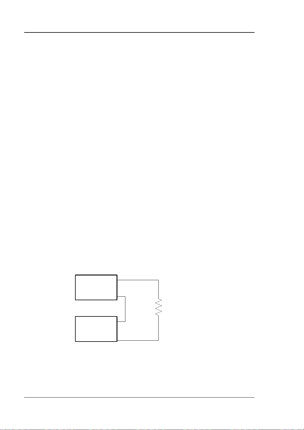
Power Supply Series Connection
Higher voltages can be provided by connecting power supplies in se ries. In this case,
the output voltage is the sum of the output voltages of all the channels. In power
supply series connection, you need to set the same current setting value and
overcurrent protection value for all the channels. Take the series connection of two
channels as an example; the connection method is as shown in the figure below.
Operation Procedures:
1. Connect the power supply and load as shown in t he figure above. Pay attention
2-8 DP800 User’s Guide
to the polarity when making connections.
Page 59
Chapter 2 Front Panel Operations RIGOL
Power Supply
Channel #
1
-
+
Power Supply
Channel #2
-
+
I
1
I
L
R
Load
I
2
IL=
I1+I
2
2. Set proper voltage, current and overcurrent protection value for each channel
(all the channels in series connection should be working in constant voltage
mode; you should set the same current setting v alue s and the same overcurrent
protection values for all the channels) by ref e rring to "Constant Voltage
Output". Turn on the output of each channel.
Note: Make sure that all the channels in series connection are working in constant
voltage mode. If one of the channels is workin g in constant current mode, the other
channels will enter critical state in which their outputs are unpredictable.
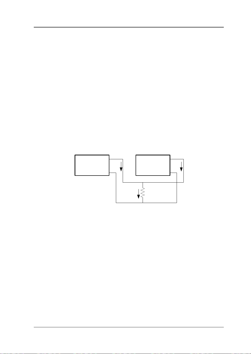
Power Supply Parallel Connection
High currents can be p rovided by connecting p ower supplies in parallel. I n this case,
the output current is the sum of the output currents of all the channels. In power
supply parallel connection, you can set the parameters of each power supply. Take
the parallel connection of two channels as an example; the connection method is as
shown in the figure below.
Operation Procedures:
1. Connect the power supply and load as shown in t he figure above. Pay attention
to the polarity when making connections.
2. Set proper parameters for each channel (all the channels can work in constan t
voltage or constant current mode) by ref errin g to "Constant Voltage Output"
and "Constant Current Output". Turn on the output of each channel .
Note: All the channels can work in constant voltage or constant current mode
according to the actual need of the load.
DP800 User’s Guide 2-9
Page 60

RIGOL Chapter 2 Front Panel Operations
Tip
is selected, users ca n quickly enable or disa ble the tra ck
functions of the two channels at the same time.
Track Function
The track function is usually used to provide symmetric voltage for the operation
amplifier or other circuit. For DP800 series power supply, the specified channels of
the following models support the track function.
DP832: CH1, CH2
DP831: CH2, CH3
For channels that support the track function, you can set the tracking states of the
voltage setting value and output on/off state respectively accord ing to you r ne e d.
To Enable the Track Functi on
Press Utility System Track Set Track to switch between "Synchronous"
and "Independent".
Independent: for two channels (the channels should be of the same
instrument) that support the track function, the status of the track function of
the other channel will not be affected when the track function of a channel is
enabled or disabled.
Synchronous: for two channels (the channels should be of the same
instrument) that support the track function, the track function of the other
channel will be enabled or disabled at the same t ime when the track f unction of
a channel is enabled or disabled.
When "Independent" is selected, users can enable or disable the track
function of a single channel freely.
When "Synchronous"
For channels (the channels should be of the same in strument) th at support th e tra ck
function, the tracking status of the channel voltage setting values is related to the
number of channels of which the track functions are enabled.
If only the track functi on of a single channel is en abled, the voltage set ting value
of the other channel will change accordingly when the voltage setting value of
this channel is modified. At this point, the voltage setting va lue of the channel of
which the track function is not enabled cannot be set and can only c h ange with
that of the channel of which the track function is enabled.
If the track functions of the two channels are both enabled, the voltage setting
value of the other channel will change accordingly when the voltage setting
value of a channe l is modified. At this point, the volta ge setting v alues of both of
the two channels can be set.
2-10 DP800 User’s Guide
Page 61

Chapter 2 Front Panel Operations RIGOL
Tip
voltage will not be affected.
The track function only tracks the voltage setting value and the actual output
You can perform the following operations according to your need.
1. Only enable the track function of a single channel and track the
voltage setting value
The operation pro cedures are as follows (in this exa mple, only the t rack fun ction
of CH1 of DP832 is enabled).
Select the "Independent" tracking mode
Press Utility System Track Set Track to select "Independent".
Enable the track function of CH1
Select CH1 and press Track to select "On". At this point, the track function
of CH1 is enabled and the tracking status icon
is displayed between
the CH1 and CH2 areas in the user interface.
Disable the track function of CH2 (ignore this step if the track function of
CH2 is currently disabled)
Select CH2 and press Track to select "Off". At this point, the track f unction
of CH2 is disabled.
Track the voltage setting value
Select CH1, press Voltage and set the desired voltage. At this point, the
voltage of CH2 changes acco rdingly. For example, se t the volt age of CH1 t o
+5V; the voltage of CH2 will change to +5V automatically.
Note: At this point, the v oltage se tt ing v alue of CH2 cannot be set and can
only change with that of CH1.
2. Enable the track functions of both of the two channels and track the
voltage setting value
First, you can enable the track functions of the two channels using any of the
following methods (take DP832 as an example).
Method 1
Select the "Synchronous" tracking mode
Press Utility System Track Set Track to select "Synchronous".
Enable the track functions of CH1 and CH2 at the same time
Select CH1 or CH2, press Track and select "On". At this point, the track
functions of CH1 and CH2 are both ena bled. The tr acking status icon
is
DP800 User’s Guide 2-11
Page 62

RIGOL Chapter 2 Front Panel Operations
displayed between the CH1 and CH2 areas in the user interface.
Method 2
Select the "Independent" tracking mode
Press Utility System Track Set Track to select "Independent".
Enable the track functions of CH1 and CH2
Select CH1 and press Track to select "On". At this point, the track function
of CH1 is enabled and the tracking status icon
the CH1 and CH2 areas in the user interface. Use the same method to
enable the track function of CH2.
Then, select CH1 or CH2 and press Voltage an d set the desired voltage. At this
point, the voltage setting value of the other channel changes accordingly. For
example, set the voltage of CH1 to +5V; the voltage of CH2 will change to +5V
automatically.
Note: At this point, both of the voltage setting values of CH1 and CH2 can be
set.
is displayed between
To Track the On/Off Status of the Channel Output
Press Utility System Track Set On/Off to selec t "Enable" or "Disable".
Disable: the output status of the other channel will not be affected when the
output of a channel is turned on or off.
Enable: for channels (the channels should be of the same instrument) that
support the track fun ction, the tracking st atus of the on/of f status of the channel
output is related to the number of channels of which the track functions are
enabled.
If only the track function o f a sin gle cha nnel is enable d (please re fer to "To
Enable the Track Function"), the output of the other channel will be
turned on or off a t t he same time when the o utput of this channel is turne d
on or off. At this point, the output status of the channel of which the track
function is not enabled cannot be set and can only change with that of the
channel of which the track function is enabled.
If the track functions of the two channels are both enabled (please refer to
"To Enable the Track Function"), the output of the other channel will be
turned on or off at the same time when the output of a channel is turned on
or off. At this point, the output status of both of the two channels can be
set.
2-12 DP800 User’s Guide
Page 63
Chapter 2 Front Panel Operations RIGOL
Tip:
Sense leads and load leads together.
Lead Equivalent
Load Lead
Sense Lead
Load Lead
Lead Equivalent
Resistance
Sense Working Mode
When the output current of the power supply is high, the voltage drop on the load
lead cannot be ignored. To ensure that the load can a cquire the cor rect voltage d rop,
CH2 of DP821 and DP811 (both provide 10A output current) provide the Sense
(remote sense) working mode. In this mode, the instrument detects the voltage at
the load terminal instead of the voltage at the output terminal of the power supply;
in this way, the instrument can automatically compensate for the voltage drop
caused by the load lead to ensu re that the power supply output v a lue set by users is
consistent with the voltage acquired by the load.
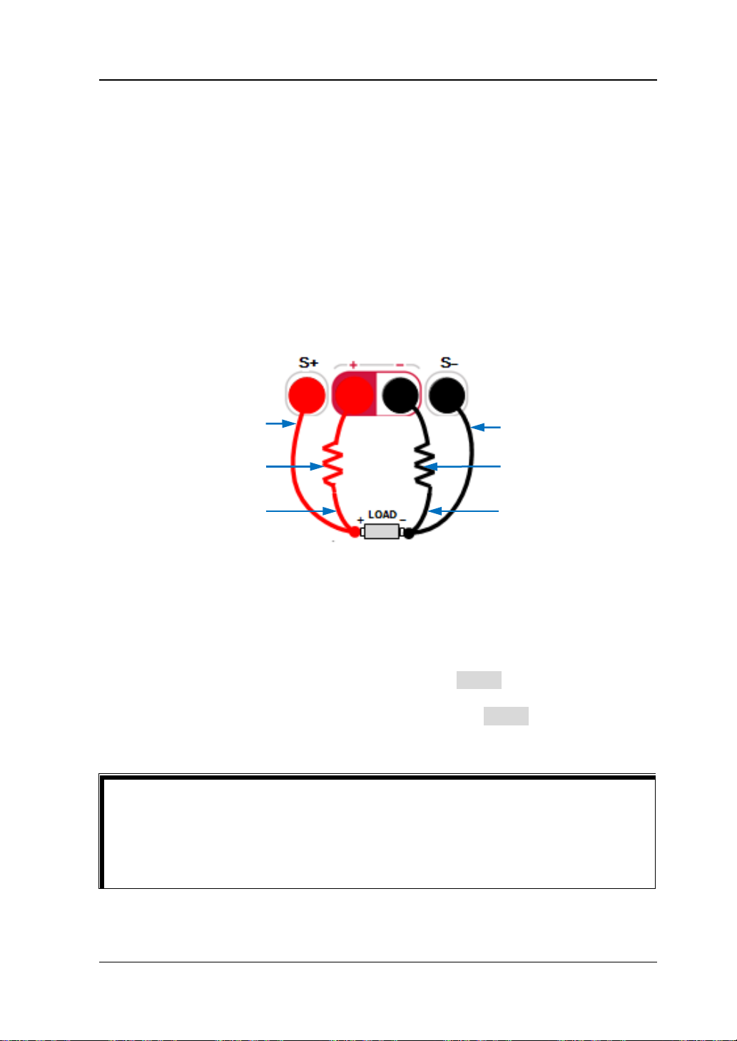
The Sense connecting method at the front panel is as shown in the figure below.
Sense Lead
Resistance
Operation Procedures:
1. Connect the channel output terminals and Sense terminals at the front panel of
the instrument to the two ends of the load respectively, as shown in the figure
above. Pay attention to the polarity when making connections.
2. For DP821: after you select C H2 (8V/10A), press Sense to turn on the Sense
function.
For DP811: after you select the desired range, press Sense turn on the Sense
function.
When the output current is high, to acquire the best output characteristics,
the load leads should be a s sho rt as p ossible an d it is recommended that you
twist the load leads together.
Twisted pairs are recommended for the Sense leads and do not twist the
In addition, the output interface a t the rear panel of DP811 can also be used for the
DP800 User’s Guide 2-13
Page 64

RIGOL Chapter 2 Front Panel Operations
Output Interface at
the Rear Panel
Connecting
Terminal
Sense working mode. The Sense connecting method at the rear panel is as shown in
the fi g ure below.
Operation Procedures:
1. Connect the load to the corresponding position on the connecting terminal
correctly as shown in the f ig ure above. Pay attention to the polarity when
making connections.
2. Insert the connecting terminal into the output interface at the rear panel of the
instrument correctly. Pay attention to the corresponding relations of the
connecting terminal and the output interface.
3. After selecting the desired range, press Sense to turn on the Sense function.
Note: The output terminals at the front panel and the output interface at the rear
panel cannot be used for the Sense mode at the same time. You can only sel ect one
of them for the Sense function at each time (wherein, the output terminals at the
front panel provide higher output accuracy).
2-14 DP800 User’s Guide
Page 65
Chapter 2 Front Panel Operations RIGOL
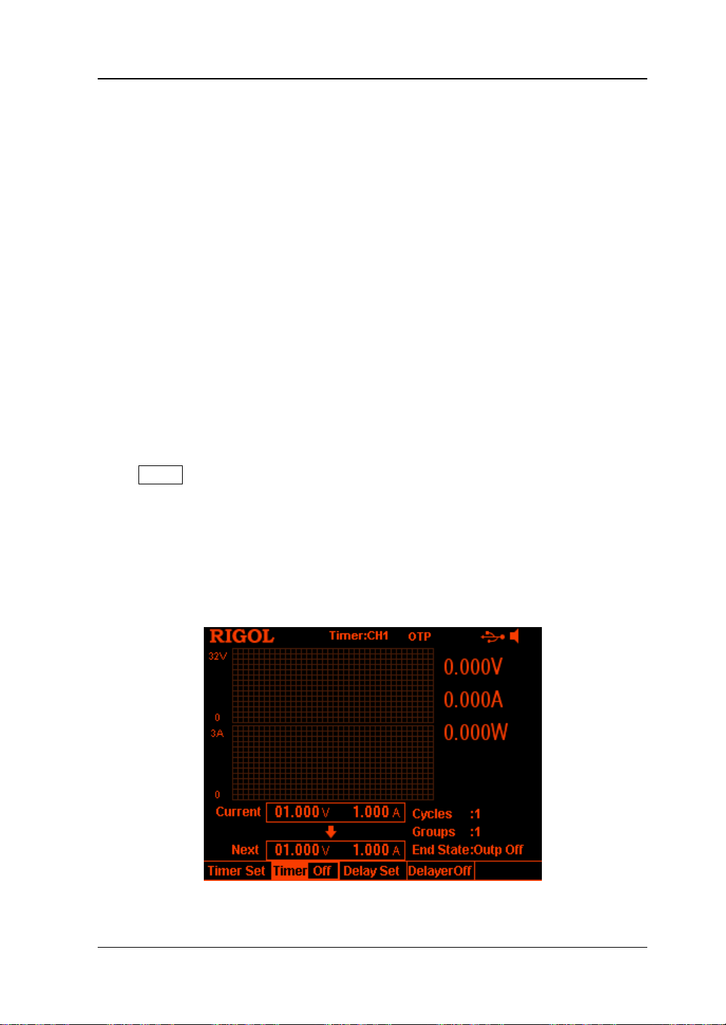
Timer and Delayer
DP800 provides the timer and delayer functions.
When the timer is enabled, the instrument outputs the preset voltage and current
values (at most 2048 groups). Users can set the number of output groups of the
timer as well as the voltage, current and timing time of each group. Besides, the
instrument provides various built-in output templets and users can select and edit
the templet as well as create timer parameters based on the templet. The instrument
will output according to the parameters currently created.
When the delayer is enabled, the instrument enables or disables the output
according to the preset state and delay time (at most 2048 groups). Users can set
the number of output groups of the delayer as well as the state and delay time of
each group.
Users can store the edited timer parameters (timer file, with the suffix "*.RTF") and
delayer parameters (delay file, with the suff ix "*.RDF") in internal or external
memory and recall them when required.
Press Timer (the backlight turns on) to open the timer and delayer interface (as
shown in Figure 2-1). The function of each menu key is as follows.
1. Timer Set: open the timer parameter setting interface and set the timer
parameters;
2. Timer: turn on or off the timer;
3. Delay Set: open the delayer parameter setting interface and set the delayer
parameters;
4. Delayer: turn on or off the delayer.
Figure 2-1 Timer and Delayer Interface
DP800 User’s Guide 2-15
Page 66

RIGOL Chapter 2 Front Panel Operations
Tip
is grayed out and disabled.
Timer Parameter Preview Channel Currently Selected Timer Parameter List
The timer function and delayer function are mutually exclusive. When the timer is
enabled, Delayer is gra yed out and disabled; when the delayer is en abled, Timer
To Set the Timer Parameters
Press Timer Timer Set to enter the timer parameter setting interface as shown
in the figure below. The channel currently sele cted is displayed in the stat us bar. You
can press the channel selection keys at the front panel to switch the channel
currently selected. This interface provides timer parameter preview; users can view
the values on the current page of the timer parameter list (the horizontal axis
denotes time and the vertical axis denotes voltage and current).
Figure 2-2 Timer Parameter Setting Interface
You can set the timer parameters in the timer parameter setting interface following
the steps below.
1. To Set the Number of Output Groups
2. To Set the Number of Cycles
3. To Set th e End State
4. To Edit the Timer Parameters
5. To Save and Read the Timer File
2-16 DP800 User’s Guide
Page 67

Chapter 2 Front Panel Operations RIGOL
Tip
The power supply will terminate the timer function when the total number of
depends on the setting in "To Set the End State".
To Set the Number o f Output Groups
The number of output groups is defined as the number of groups of preset voltage
and current values that the power supply outputs in each cycle. Press Groups and
use the numeric keyboard or the left/right direction k ey and knob to input the desired
value. The range is from 1 to 2048.
To Set the Number of Cycles
The number of cycles is defined as the number of times that the i nstrument performs
timing output according to the preset voltage and current. Press Cycles to set the
number of cycles to "Infinite" or use the numeric keyboard or the left/right direction
key and kno b to inpu t th e desired value. The range is from 1 to 99999.
The total number of groups in timin g out put = t he n umber of output groups*
the number of cycles
groups of outputs is finished. At this point, the state of the power supply
To Set the End State
The end state refers to the state of the instrument after it finishes outputting the
total number of gr oups of voltage an d cur rent v alues when t he num be r of cy cles is a
specif ied value. Press End State to select "Outp Off" or "Last".
Outp Off: the instrument turns off the output automatically after finishing the
output.
Last: the instrument stops at the output state of the last group after finishing
the output.
Note: When the number of cycles is set to "Infinite", the end state is invalid.
To Edit the Timer Parameters
You can edit the timer parameters manually or using the built-in templet.
DP800 User’s Guide 2-17
Page 68

RIGOL Chapter 2 Front Panel Operations
To Edit the Timer Parameters Manually
You need to set P groups (No.0 to No.(P-1)) of tim er parameters; wherein, P is the
number of output groups currently set. On ly 6 groups of parameters can be
displayed on each page o f the ti mer para meter list an d you can press
or to
view and set the parameters of the other groups. This interface provides timer
parameter preview; users can view the values on the current page of the timer
parameter list (the horizontal axis represents time and the vertical axis represents
voltage and current).
1. Press Parameter and use the numeric keyboard, the left/right direction ke y or
the knob to select the specified number (No.) in the timer parameter list.
2. Use the up/down di rection key t o select the v oltage (V), current (C) and time (s )
of the curre nt g r ou p re spe cti ve ly an d use th e n ume ri c k e yb oa rd o r th e le ft /ri gh t
direction key and knob to input the desired value.
3. Use the same method to set the parameters of the other groups.
To Edit the Timer Parameters using Templet
The instrument provides various built-in output templets. Users can select the
desired templet, edit the timer parameters using the templet and create waveform.
The instrument will output according to the waveform currently created.
Press Templet to open the templet editing menu. Y ou can edit the timer parameters
according to the steps below.
1. Select the editing object
2. Select the templet
3. Edit the timer parameters
4. Construct the output waveform
1. Select the editing object
Press Edit Obj to select "Voltage" or "Current".
Voltage: when it is selected, the interface displays the voltage preview and
you can set all the gr oups t o output a fixed current. Press Current and use
the numeric keyboard or the left/right direction key and knob to set the
current value.
Current: when it is selected, the interface displays the current preview and
you can set all t he gr oups to output a fixed voltage. Press Voltage and use
the numeric keyboard or the left/right direction key and knob to set the
voltage value.
2. Select the te mplet
Press Type to select the desired templet, including Sine, Pulse, Ramp, Stair Up,
Stair Dn, StairUpDn, Exp Rise and Exp Fall.
2-18 DP800 User’s Guide
Page 69

Chapter 2 Front Panel Operations RIGOL
T
t
Tip
templet repeatedly by increasing the number of cycles.
Sine
The Sine waveform is as shown in the figure below. The instrument
determines the Sine amplitude according to the maximum and minimum
currently set and determines t he Sine period according to the total number
of points (denoted by P) and the time interval currently set, thus
determining the Sine waveform. When creating par ameters, the instrument
draws P values from the preset Sine waveform according to the current
time interval.
T
Pulse
The Pulse waveform is as shown in the figure below. The timer parameters
created from Pulse waveform only contain two groups of data.
The f ir st group: the amplitude (voltage or current) is determined by the
high level set; the time equals the pulse width (t) currently set.
The second group: the amplitude (voltage or current) is determined by the
low level set; the t ime equals the period currently set minus the pulse w idth
currently set (T-t).
When Pulse is selected, if you want to output more t han 2 groups of timer
parameters, you can output the timer parameters created from the Pulse
DP800 User’s Guide 2-19
Page 70

RIGOL Chapter 2 Front Panel Operations
T
t
Symmetry=t/T*100%
Ramp
The Ramp waveform is as shown in the figure below. The instrument
determines the amplitude of the Ramp according to the maximum and
minimum currently set, determines the period according to the total
number of points (denoted by P) and the time interval currently set and
determines the Ramp waveform according to the symmetry (denoted by
Sym) currently set. When creating parameters, the instrument draws
[1]
int(P*Sym)
values from the rising edge of the preset Ramp wavefo rm at
the same time interval and draws P-int(P*Sym) values from the falling
edge of the preset Ramp waveform at the same time interval. The timing
time is determined by the time interval currently set.
[1]
Note
: int(P*Sym) refers to rounding P*Sym (discard the decimal part).
Stair Up
The Stair Up waveform is as shown in the figure below. The instrument
determines the Stair Up wavefo rm accord ing to the maximum (de noted by
MAX), minimum (denoted by MIN), total numbe r of p oin ts ( den ot ed by P,
P≥10) and time interval currently set and creates P parameters from MIN
to MAX at the step of (MAX-MIN)/(P-1). The timing time is determined
by the time interval currently set.
Stair Up
Stair Dn
The Stair Dn waveform is as shown in the figure below. The instrument
determines the Stair Dn waveform accor ding to the maximum (d enoted by
MAX), minimum (denoted by MIN), total number of poi nts (den oted by P)
and time interval currently set and creates P parameters from MIN to MAX
at the step of (MAX-MIN)/(P-1). The timing time is determined by the
time interval currently set.
Stair Dn
2-20 DP800 User’s Guide
Page 71

Chapter 2 Front Panel Operations RIGOL
StairUpDn
The StairUpDn waveform is as shown in the figure below. The instrument
determines the StairUpDn waveform according to the maximum (denoted
by MAX), minimum (denoted b y MIN), total number of points (denoted by
P) and time interval currently set and creates P parameters. When P is an
odd number, the value increase from MIN to MAX at the step of
(MAX-MIN)/int(P/2)
[1]
and then reduces to MIN at the same step.
When P is an even number, the value increases from MIN to MAX at the
step of (MAX-MIN)/{int(P/2)-1} and then reduces to MIN at the step
of (MAX-MIN)/int(P/2). The timing time is determined by the time
interval currently set.
StairUpDn
[1]
Note
: int(P/2) indicates rounding P/2 (discard the decimal part).
Exp Rise
The Exp Rise waveform is as shown in the figure below. The instrument
determines the Exp Rise waveform according to the maximum (denoted by
MAX), minimum (denoted by MIN), total number of points (denoted by P),
time interval and rise index (denoted by RiseIndex) currently set. The
waveform function is (MAX-MIN)*(1-e
-i*RiseIndex/P
); wherein, i is
independent variable and c reate s P groups of parameters from 0 to (P-1).
The timing time is determined by the time interval currently set.
Exp Rise
DP800 User’s Guide 2-21
Page 72

RIGOL Chapter 2 Front Panel Operations
Note
rise index or fall index currently set. The larger the rise index or fall index is, the
Exp Fall
The Exp Fall waveform is as shown in the figure below. The instrument
determines the Exp Fall waveform according to the maxim um (denoted by
MAX), minimum (denoted by MIN), total number of points (denoted by P),
time interval and fall inde x (denote d by FallIndex) currently set. The
waveform functi on is (MAX-MIN)*e
-i*FallIndex/P
; wherein, i is independent
variable and creates P groups of parameters from 0 to (P-1). The timing
time is determined by the time interval currently set.
Exp Fall
When the templet cur rently sele cted is Exp Rise or Exp Fall, the timer parameters
created cannot reach the maximum or minimum due to the characteristic of the
exponential function. The range of the timer parameters created is related to the
larger the range of the tim e r p arameters will be, as shown in the figures below
(maximum=8, minimum=0, total num ber of points=100, rise indexes/fall inde xes
are 1, 4, 7 and 10 respectively).
2-22 DP800 User’s Guide
Page 73

Chapter 2 Front Panel Operations RIGOL
Templet
Parameter
Sine
Max Value, Min Value, Points, Interval, Inverted
Pulse
Hi Level, Lo Level, Width, Period, Inverted
Ramp
Max Value, Min Value, Points, Interval, Symmet ry, Inverted
Stair Up
Max Value, Min Value, Points, Interval
Stair Dn
Max Value, Min Value, Points, Interval
StairUpDn
Max Value, Min Value, Points, Interval
Exp Rise
Max Value, Min Value, Points, Interval, Rise Index
Exp Fall
Max Value, Min Value, Points, Interval, F a ll Index
3. Edit the timer parameters
For different templets, the timer parameters to be set are different as shown in
Table 2-1.
Table 2-1 Timer parameters (templet)
Max Value
Set the maximum voltage or current of the templet currently selected. The
range is related to the channel currently se lected. It should be greater than
or equal to the minimum value currently set.
Min Value
Set the minimum voltage or current of the templet currently selected. The
range is related to the channel currently selected. It should be lower than or
equal to the maxim um value currently set.
Points
Set the total number of poi nts (na mely the number of output groups i n the
timer parameters) of the templet currently selected. The range is from 10 to
2048.
When the total number of points ( denoted by P) and the current numbe r of
output groups (denoted by G) are different, the number of output groups
will change to P automatically after output waveform is created using the
templet.
Interval
Set the time interval between the points (the time required for the
instrument to output each group of timer parameters) of the templet
currently selected. The range is from 1s to 99999s.
Inverted
When the templet currently selected is Sine, Pulse or Ramp, if invert is
enabled, the instrument will first turn the preset waveform upside down
and then create the output waveform.
DP800 User’s Guide 2-23
Page 74

RIGOL Chapter 2 Front Panel Operations
Tip
currently set. The actual range is from 1s to (Period-1s).
Tip
99999s.
Hi Level
When the templet currently selected is Pulse, set the high level of the Pulse
and the range is related to the channel currently selected. It should be
greater than or equal to the low level currently set.
Lo Level
When the templet currently selected is Pulse, set the low level of the Pulse
and the range is related to the channel currently selected. The low level
should be lower than or equal to the high level currently set.
Width
When the templet currently selected is Pulse, set the positive pulse width of
the Pulse (namely the duration of high level within a period). The range is
from 1s to 99998s.
The actual range of the positive pulse width is related to the period
Period
When the templet currently selected is Pulse, set the period of the Pulse
and the range is from 2s to 99999s.
The actual range of the period is related to the positive pulse width
currently set. The actual range is from (Positive Pulse Width+1s) to
Symmetry
When the templet currently selected is Ramp, set the symmetry of the
Ramp (namely the ratio of the dur ation o f the rising edge within a period to
the whole pe riod) and th e range is from 0% to 100%.
Rise Index
When the templet currently selected is Exp Rise, set the rise index of the
Exp Rise and the range is from 0 to 10.
Fall Index
When the templet currentl y selected is Exp Fall, set the fall index of the Ex p
Fall and the range is from 0 to 10.
4. Construct the output waveform
After editing the timer parameters (templet), press Construct to construct the
output waveform. The timer parameters corresponding to the output waveform
constructed are displayed in the timer parameter list as shown in
2-24 DP800 User’s Guide
Figure 2-2.
Page 75
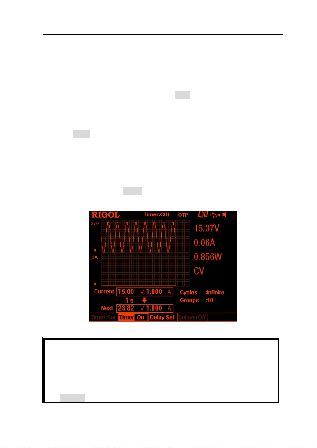
Chapter 2 Front Panel Operations RIGOL
Tip
Delayer is grayed out and disabled.
To Save and Read the Timer File
You can store the timer parameters edited manually or using the templet in internal
or external memory and recall them when required.
1. Save
After editing the timer parameters, press Save to enter the store and recall
interface. The file type is fixed at "*.rtf" and please sav e the timer file according
to the introduction in "
2. Read
Press Read to enter the store and recall interface. Th e file type is fixed at "*.rtf"
and please read the desired f ile according to the introduction in "
can edit the timer file read.
Save".
Read". Users
To Enable the Timer
After setting the timer parameters, re tur n to the timer and delayer interface (as
shown in Figure 2-1). Press Timer to enable the timing output. The timing output
interface is as shown in the figure below.
Enabling the timer will change the output value of the channel; make sure
that the change in the output value will not affect the device connected to
the power supply before enabling the timer.
The timing output is valid only when both the timer and the channel output
are turned on.
When the timer is enabled, the timer parameters cannot be modified and
DP800 User’s Guide 2-25
Figure 2-3 Timing Output Interface
Page 76
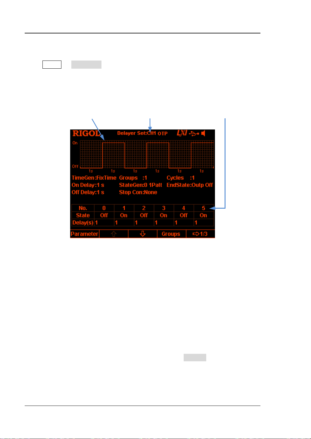
RIGOL Chapter 2 Front Panel Operations
Delay Parameter Preview Channel Currently Selected Delay Parameter List
To Set the Delay Parameters
Press Timer Delay Set to enter the delay parameter setting interface as shown
in the figure below. The channel currently selected is displayed in the status bar.
Press the channel selection keys at the front panel to switch the channel currently
selected. This interface provides delay parameter preview. Users can view the values
on the current page of the delay parameter list (high level indicates turning on the
output and low level indicates turning off the output).
Figure 2-4 Delay Parameter Setting Interface
You can set the delay parameters in the delay parameter setting interface following
the steps below.
1. To Set the Number of Output Groups
2. To Set the Number of Cycles
3. To Set th e End State
4. To Edit the Delay Parameters
5. To Set th e Stop Conditi on
6. To Save and Read th e Delay Fil e
To Set the Number o f Output Groups
The number of output groups refers to the number of times that the instr ument turns
on or off the output according to the preset state. Press Groups; use the numeric
keyboard or the left/right direction key and knob to input the desired value. The
range is from 1 t o 2048.
2-26 DP800 User’s Guide
Page 77

Tip
the End State".
Chapter 2 Front Panel Operations RIGOL
To Set the Number of Cycles
The number of cycles refers to the number of times that the instrument performs
delay output according to the preset state. Press Cycles to set the number of cycles
to "Infinite" or use the numeric keyboard or the left/right direction key and knob to
input the desired value. The range is from 1 to 99999.
The total number of groups in delay output = the number of output
groups*the number of cyc le s
The power supply will terminate the delay function when the instrument
detects the state that meets the condition set in "To Set the Stop
Condition" or when the total number of groups of delay outputs is finished.
At this point, the state of the power supply depends on the set ting in "
To Set
To Set the End State
The end state refers to the state of the instrument when the delay function is
terminated. Press End State to select "Outp On", "Outp Off" or "Last".
Outp On: the instrument turns on the output automatically.
Outp Off: the instrument turns off the output automatically.
Last: the instrument stops at the output state of the last group.
To Edit the Delay Parameters
You can edit the dela y parameters manually or generate the delay parameters
automatically using the built-in pattern and built-in method.
To Edit the Delay Parameters Manually
You need to set P groups (No.0 to No.(P-1)) of delay parameters; wherein, P is the
number of output groups currently set. Only 6 groups of parameters can be
displayed on each page of the delayer parameter list and you can press
to view and set the parameters of the other groups. This interfac e provides delay
parameter preview and users can view the values on the current page of the delay
parameter list (high level indicates turning on the output and low level indicates
turning off the output).
1. Press Parameter and use the numeric keyboard or the left/right direction key
or the knob to select the specified number (No.) in the delay parameter list.
or
DP800 User’s Guide 2-27
Page 78

RIGOL Chapter 2 Front Panel Operations
2. Use the up/down direction key to select the state (State) and time (Delay) of the
current group respectively .
When state (State) is selected, press OK to switch to the desired state; when
time (Delay) is selected, use the numeric keyboard or the left/right direction k e y
and knob to input the desired value.
3. Use the same method to set the parameters of the other groups.
To Generate the Delay Parameters Automatically
The instrument provides v arious kinds of built -in patterns and built-in time sequence
generation algorithms used to automatically generate delay on/off state and time
sequence respectively. Users can select the state generation mode and time
sequence generation mode and the instrument will generate the delay parameters
automatically according to the current settings.
1. Select the state generation mode
Press State Gen 0 1 Patt (1 0Patt) to select "0 1 Patt" ("1 0 Patt").
0 1 Patt: the s tate i s set to "Off" and "On" alternately.
1 0 Patt: the sta te i s set to "On" and "Off" alternately.
The instrument will generate the on/off state automatically according to the
current setting and the length is the number of output groups currently set.
2. Select the time generation mode
1) Select the generation method
Press Time Gen Method to select "FixTime", "Increase" or "Decline".
FixTime
Users set the output on delay time (on delay, namely the duration
when the output status is "On") an d the output off dela y time (off delay,
namely the duration when the output status is "Off").
Increase
Generate the on/off delay time by increasing from the time base value
at the specified step. Users can set the time base value and step.
Decline
Generate the on/off delay time by declinin g from the time base value at
the specified step. Users can set the time base value and step.
2) Set the on delay/off delay
When the time generation method i s "FixTime", users need to set the
output on delay time and output off delay time.
Press Time Gen On Delay (Off Delay); use the numeric keyboard or
the left/right direction key and knob to input the desired value. The ranges
of on delay and off delay are both from 1s to 99999s.
2-28 DP800 User’s Guide
Page 79

Chapter 2 Front Panel Operations RIGOL
3) Set the time base value and step
When the time generat ion metho d is "Increase" or "Decline", users need to
set the time base value and step.
Press Time Gen Base Val (Step); use the numeric keyboard or the
left/right direction key and knob to input the desired value. The minimum
time base value and step are both 1s and the two fulfills the relation: time
base value + number of output groups*step ≤99999s.
To Set the Stop Condition
The instrument monitors the out put volta ge, current and power d uring dela y output.
You can set a stop condition and the instrument terminates the delay function (no
matter whether the total n umber of groups of delay outputs are finished) when state
that fulfills this condition is detected. At this point, the state of the instrument is
determined by the setting in "To Set the End State
".
Press Stop Con to set the stop condition to "None", "< Voltage", "> Voltage", "<
Current", "> Current", "< Power" or "> Power". After selecting the desired condition,
use the nu meric ke yboard or the left/ right direction k ey and kno b to input the desired
value (you do not need to set this parameter when the stop condition is set to
"None").
To Save and Read the Delay File
You can save the delay parameters edited manually or generated automatically in
internal or external memory and recall them when required.
1. Save
After finishing editing the delay parameters, press Save to enter the store and
recall interface. The file type is fixed at "*.rdf" and please save the file according
to the introduction in "
2. Read
Press Read to enter the store and recall interface. The f ile type is fixed at
"*.rdf" and please read t he desire d file according to the intro duction i n "
Users can edit the delay f ile read.
Save".
Read".
DP800 User’s Guide 2-29
Page 80

RIGOL Chapter 2 Front Panel Operations
Tip
and Timer is grayed out and disabled .
To Enable the Delayer
After setting the delay parameters, return to the timer and delayer interface (as
shown in Figure 2-1). Press Delayer to enable the delay output. The delay output
interface is as shown in the figure below.
Figure 2-5 Delay Output Interface
Enabling the delayer will change the output state of the channel. Please
make sure that the change of the output state will not affect the devices
connected to the power supply before enabling the delayer.
When the delayer is enabled, the delayer parameters cannot be modified
2-30 DP800 User’s Guide
Page 81

Chapter 2 Front Panel Operations RIGOL
Advanced Functions
DP800 provides various advanced functions, including the recorder, analyzer
(option
function setting interface.
1. Recorder: record the output state of each channel and store the record file.
2. Analyzer: analyze the record file saved.
3. Monitor: monitor the output of each channel and turn off the output, display
4. Trigger: the rear panel provides a digital I/O interface which supports trigger
Note
to the order nu mber pro vided in "Appendix A: Acce ssories and Options" in this manual and
install the option correctly (refer to "Options") before using the function.
.
[1]
), monitor (option) and trigger (option). Press to open the advanced
the corresponding prompt message or sound the beeper when the monitor
condition is met.
input and trigger output.
Trigger Input: the data lines of the digital I/O interface receive external
trigger signal. The source under control (namely the output channel) turns
on the output, turns off the output or inverts the output state when the
preset trigger condition is met.
Trigger Output: the data lines of the digital I/O inte rf ace output the level or
square signal when the output of the control source (namely the output
channel) meets the preset trigger condition.
[1]
: For f unction marked with "option", you need to order the corresponding option according
DP800 User’s Guide 2-31
Page 82

RIGOL Chapter 2 Front Panel Operations
Recorder
When the recorder is enabled, users can record the current state of the instrument
and if an analyzer is installed, users can also analyze the file recorded.
Press Recorder to open the recorder setting interface. You can turn on or
off the recorder function, set the record period and select the store destination.
Note: When the recorder is turned on, the record period and storage destination
cannot be set. Therefore, please set the record period and storage destination before
turning on the recorder.
You can record and save the record file following the steps below.
1. Set the record period
The record period is the time interval at which the instrument samples and
records the output of each channel when the recorder is turned on. Press
Period and use t he numeric ke yboard or the left /right direction key and knob to
set the desired value. The range is from 1s to 99999s and the default is 1s.
2. Set the storage destination
Press Dest to enter the store and recall interface and the f ile type is fixed at
"*.rof". After s electing the desire d destination, press Save and inp ut the desired
filename (for the detailed operatio ns, refer t o the int rodu ction in "
press OK.
Note:
You can store the record file in the internal or external memory. In one
record operation, the recorder can recor d up to 2048 po ints when the
internal memory is selected or 614400 points when the external memory is
selected.
When the recorder is turned off, the instrument will store the record file
with the specified filename to the specified destination according to the
settings in this step.
3. Turn on or off the recorder
Press Switch to turn on the recorder. The instrument samples an d re co r ds
the output of each channel by using the current record period as the time
interval.
Press Switch to turn off the recorder. When the recorder is turned off, the
current record is finished; press OK and the instrument will store the
recorded file to the specified destination a ccording to t he set tings in step 2.
Note:
During the record, make sure that the output of each channel is enabled;
otherwise, the record data will be 0.
You can only store the record file when at least a single point is recorded.
Save"); then,
2-32 DP800 User’s Guide
Page 83

Chapter 2 Front Panel Operations RIGOL
Analyzer (option)
The analyzer can analyze the file recorded and provides the analysis results of the
channel voltage, cu rr e n t and powe r, such as the average, VAR and range.
Press Analyzer to open the analyzer setting interface. You can ope n t he
record file stored, set the analyzer parameters, execute analysis and view the
analysis results.
You can analyze the stored record file and view the analysis results following the
steps below.
1. Open the record file
Press Open File to enter the store and rec all int er face and the file type is fixed
at "*.rof". Select the desired record file and press Read.
At this point, the current time and start time are both the record period of the
fil e open ed. When the number of groups of the file opened is less than or
equal to 2048, the end time is the maximum record time (the number of
groups*the record period of the record file opened) of the record file opened;
when the number of groups of the file opened is greater than 2048, the end
time is the record period of the file opened*2048.
Note: The following operations are valid only when valid record file is opened.
2. Set the analysis parameters
Start Time
Press Start Time and use the numeric keyboard or the left/right direction
key and kno b to set th e start time of the reco rd file analysis. The range is
from the record period of the file opened to the current end time.
End Time
Press End Time and use the numeric keyboard or the left/right direction
key and kno b to set th e end time of the record file analysis. When the
number of groups of the file opened is less than or equal to 2048, the
range is from the start time to the maximum record time (the number of
groups*the record period) of the file opened; when the number of
groups of the file opened is greater than 2048, the range is from the start
time to the record period of the file opened*2048.
3. Execute the analysis
Press Analyze and the instrument will start to analyze the record file opened
according to the current setting. The analysis results include various statistic
parameters of the channel voltage, current and power, su ch as the average, VAR
and range.
DP800 User’s Guide 2-33
Page 84

RIGOL Chapter 2 Front Panel Operations
Tip
Time".
4. View the analysis results
After the analysis is finished, you can view the a nalysis results ac cording to y our
need.
Analysis object
Press Object to select "Voltage", "Current", "Power" or "ALL" and the
corresponding analysis results will be displayed at the bottom of t he scree n.
Note: When "ALL" is selected, you can press the up/down d i rectio n key to
switch the current analysis object and view the corresponding analysis
results.
Display type
The data between the start time and end time in the record file currently
opened will be displayed in figure or table form at the upper side of the
screen.
Press Disp Type continuously to select figure or table display form.
Figure
Display the voltage, current or power (depend on the analysis object
currently selected) corresponding to the current channel of the rec o rd file
opened in figure form. Each group of measurement values of each object
are connected in linear interpolation mode, clearly showing the variation
tendency. At the same time, the data corresponding to the "Current Time" is
displayed above the f igure.
You can view the analysis results of the specified channel by
switching the current channel.
You can set the analysis object to display the specified type of data
(voltage, current or power) at the upper side of the screen.
You can view the specified group of data by setting the "
Current
2-34 DP800 User’s Guide
Page 85

Chapter 2 Front Panel Operations RIGOL
Tip
Time".
Table
Display each group of voltage, current and power of the current channel in
the record file opened in table form.
You can view the analysis results of the specified channel by
switching the current channel.
You can view the specified group of data by setting the "
Current
Current Time
You can quickly locate each group of data of the record file opened
between the start time and end time by setting the current time. If the
current display mode is figure, the interface will lo cate the current data (the
voltage, current or power corre sponding to the "Current Time" is displayed
above the figure) using a cursor line in the color corresponding to the
current channel.
Press Cur Time and use the numeric keyboard or the left/right direction
key and knob to set the desired value. The ra nge is from the s tart time to
the end time.
DP800 User’s Guide 2-35
Page 86

RIGOL Chapter 2 Front Panel Operations
Monitor (option)
The monitor can monitor the current output state of the instrument. When the
user-defined monitor condition is met, the instrument executes the corresponding
operation according to the setting in "Stop Mode
Press Monitor to open the monitor setting interface. The status bar s how s
the channel currently sele cted. Press the channel s ele ction k eys at t he f ront pa nel to
switch the channel.
Note: The instrument can monitor the output states of multiple channels
simultaneously.
You can set the monitor condition and turn on or off the monitor function following
the steps below.
1. Monitor Condition
The monitor condition can be any logic combination of voltage, curre n t and
power and users can also set the voltage, current and power values.
Press Condition and use the directi on keys and OK to set the desired monitor
condition.
2. Voltage
Press Voltage and use the numeric keyboard or the left/right direction key and
knob to set the voltage in the monitor condition.
3. Current
Press Current and use the numeric keyboard or the left/right direction key and
knob to set the current in the monitor condition.
4. Power
Press Power and use the numeric keyboard or the left/right direction key and
knob to set the power in the monitor condition.
5. Stop Mode
When the channel output state meets the monitor condition se t, the instrument
will turn off the output, display the correspo nding p rompt mess age or sound the
beeper acco rdin g to the stop mode selecte d. The stop mode can be one or more
of "Output Off", "Warning" and "Beeper".
Press Stop Mode and use the direction keys to select the specified stop mode
("Output Off", "Warning" and "Beeper"); then, press OK to enable or disable th e
stop mode selected.
6. Switch
Press Switch to turn on or off the monitor function.
".
2-36 DP800 User’s Guide
Page 87

Chapter 2 Front Panel Operations RIGOL
Digital I/O Interface at the Rear Panel Connecting Terminal
Trigger (option)
The rear panel of DP800 provi des a digital I/O int erf ace whi ch s upports t rigger input
and trigger output.
Trigger Input:
The data lines of the digital I/O interface receive external trigger signal. The
source under c ont rol (nam ely the out put channel ) turns on the output, turns off
the output or inverts the output state when the preset trigger condition is met.
Trigger Output:
The data lines of the digital I/ O inter face output level or square si gnal w hen t he
output of the control source (namely the output channel) meets the preset
trigger condition.
The 4 data lines of the digital I/O interface are mutually independent and can be
used as trigger input or trigger output separately.
The trigger connections are as shown in the figure below.
Operation Procedures:
1. Connect the cables to the connecting terminals according to the figure above
(pay attention to the corresponding relations).
2. Insert the connecting terminals into the digital I/O interface at the rear panel
(pay attention to the corresponding relations).
Press Trigger to open the trigger setting interface as shown in the figure
below. Press Trig to select trigger input or trigger output and the corresponding
setting interface is opened. The default is trigger input.
DP800 User’s Guide 2-37
Page 88

RIGOL Chapter 2 Front Panel Operations
Tip
and noise to l er a nce is 0.4V.
Figure 2-6 Trigger Setting Interface
Trigger Input
When signal th at meets the current trigger type is input on the specified data line,
the specified source under control will turn on the output, turn off the output or
toggle the output state according to the setting in output response.
Press Trigger Trig to select "In" and the trigger input set ting interface is
opened, as shown in Figure 2-6.
1. Data Line
Press Data Line to select D0, D1, D2 or D3 and the data line cur rently selected
will be highlighted on the screen. Users can set the t rigger conditions of the f our
data lines respectively.
2. Source under Control
Press Ctrled Src to select one or more of CH1, CH 2 and CH3 as the source
under control.
3. Trigger Type
Press Trig Type to sele ct to trigger on the rising edge, fallin g edge, high le vel or
low level of the input signal.
For the input signal, high level is from 2.5V to 3.3V , low level is from 0V to 0.8V
4. Output Response
Press Outp Resp to set the output response type to "Output On", "Output Off"
2-38 DP800 User’s Guide
Page 89

Chapter 2 Front Panel Operations RIGOL
or "Output Toggle".
Output On: when the trigger condition is met, turn on the output of the
channel currently selected as the source under control.
Output Off: when the trigger condition is met, turn off the output of the
channel currently selected as the source under control.
Output Toggle: when the trigger condition is met, turn the wav efo rm of the
channel currently selected as the source under control upside down an d
then output the waveform.
5. Sensitivity
Press Sensitivity to set the sensitivity to high, middle or low. Selecting
relatively lower trigger sensitivity can avoid mis-trigger at the noise.
6. Enable
Press Enable to enable or disable the trigger input function of the
corresponding data line.
Trigger Output
When the output of the specif ied control source meets the trigger condition, the
specif ied data line outputs level or square waveform according to the setting of the
output signal.
Press Trigger Trig to sel ect "Out" and the trigger output setting
interface is opened, as shown in the figure below.
Figure 2-7 Trigger Output Setting Interface
1. Data Line
Press Data Line to select D0, D1, D2 or D3 and the data line cur rently selected
will be highlighted on the scree n. Users can set the t rigger conditions of the four
data lines respectively.
2. Control Source
Press Ctrl Src to select any of CH1, CH2 and CH3 as the control source.
DP800 User’s Guide 2-39
Page 90

RIGOL Chapter 2 Front Panel Operations
3. Trigger Condition
Press Condition to open the trigger condition setting interface and users can
set the trigger condition of trigger output.
Outp Trig: the instrument triggers when the output of the control source is
turned on or off.
Press Outp Trig and use the up/down direction key to select "Output Off"
or "Output On".
Volt Trig: the instrument triggers when the output voltage of the control
source meets the voltage condition set.
Press Volt Trig and use the up/down direction key to select ">", "<" or "=";
use the numeric keyboard or the left/rig ht direction key an d knob to set the
voltage value.
Curr Trig: the instrument triggers when the output current of the control
source meets the current condition set.
Press Curr Trig and use the up/down direction key to select ">", "<" or "=";
use the numeric keyboard or the left/rig ht direction key an d knob to set the
current value.
PowerTrig: the instrument triggers when the output power of the control
source meets the power condition set.
Press PowerTrig and use the up/down direction key to select ">", "<" or
"="; use the numeric keyboard or the left/right direction key and knob to
set the power value.
Auto Trig: when the trigger output is enabled, the instrument triggers
automatically.
4. Output Signal
Press Signal to set the signal type of the trigger output to "Level" or "Square".
Level: the output high level is from 2.6 V to 3.5V and the output l ow level is
from 0V to 0.4V.
Square: press Period to set the square period and the range is from 100μs
to 2.5s; press Duty to set the duty cycle of the square waveform and the
range is from 10% to 90%.
5. Polarity
Press Polarity to set the polarity of the trigger output signal to "Positive" or
"Negative".
Positive: output the signal selected in Signal when the trigger condition is
met.
Negative: turn the signal selected in Signal upside down and then output
the signal when the trigger condition is met.
6. Enable
Press Enable to enable or disable the trigger output function of the
corresponding data line.
2-40 DP800 User’s Guide
Page 91

Chapter 2 Front Panel Operations RIGOL
Display Setting
Press Display at the front panel to e nter the int erfac e as shown in the figure below.
You can set the screen brightness, contrast, RGB luminance, display mode and
display theme. Besides, you can also define the start-up interface.
Figure 2-8 Display Setting Interfa ce
Brightness
Press Display Brightness and use the knob, left/right direction key or numeric
keyboard to set the brightness of the screen. The ra nge is from 1 % to 100% and the
default is 50%. This setting is stored in the non-volatile memory and will not be
affected by factory reset.
Contrast
Press Display Contrast and use the knob, left/right direction key or numeric
keyboard to set the contrast of the screen. The range is from 1% to 100% and the
default is 25%. This setting is stored in the non-volatile memory and will not be
affected by factory reset.
RGB Luminance
Press Display RGB Lum and use the knob, left/right direction key or numeric
keyboard to set the RGB luminance of the screen. The range is from 1% to 100%
and the default is 50% . This set ting is store d in the n on-v olatile memory and will not
be affected by factory reset.
DP800 User’s Guide 2-41
Page 92
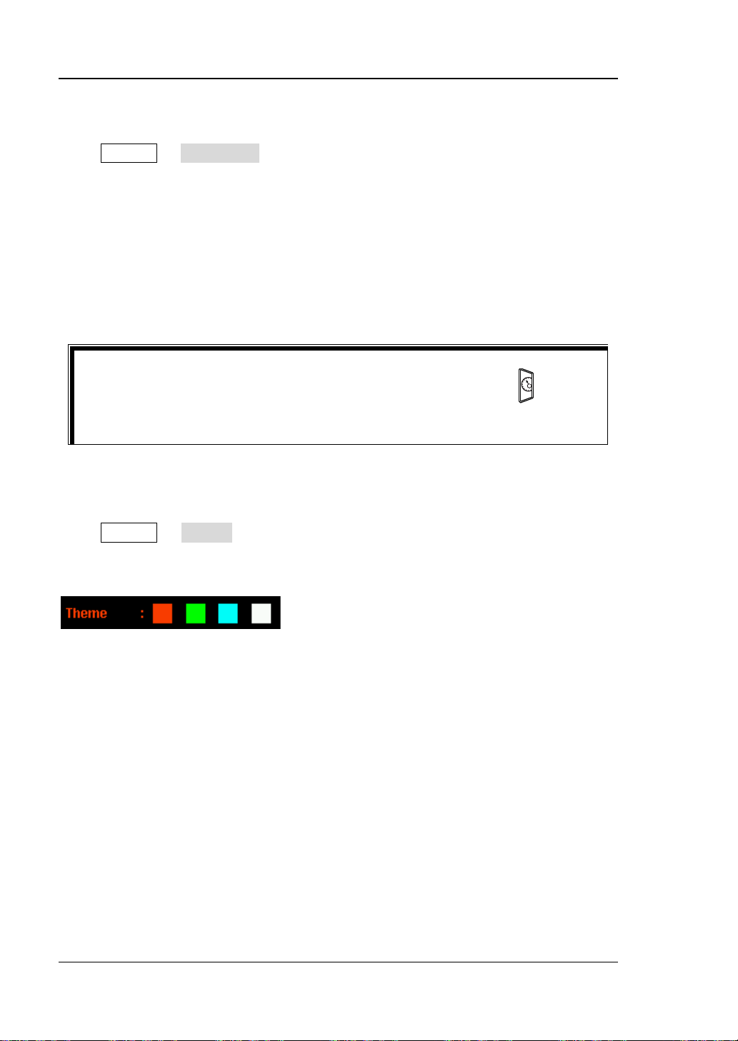
RIGOL Chapter 2 Front Panel Operations
Tip
mode.
Display Mode
Press Display Disp Mode to set the display mode to "Normal", "Waveform" or
"Dial". The default is normal display mode. This setting is stored in the non-volatile
memory and will not be affected by factory reset.
Normal: display the voltage, current and power values of all the channels in
number form.
Waveform: display the voltage, current and power values of the channel
currently selected in waveform and number forms.
Dial: display the voltage, current and power value of the channel currently
selected in dial and number forms.
When the current display mode is "Normal" or "Waveform", press at the
front panel to quickly swit ch between the current displa y mode and dial display
Display Theme
Press Display Theme and use the left/right direction key to set the display
theme to orange, green, blue or white. The default is green. T his setting is stored in
the non-volatile memor y and will not be aff ected by factory reset.
2-42 DP800 User’s Guide
Page 93

Chapter 2 Front Panel Operations RIGOL
Area 1
Area 2
User-defined Start-up In te rfa ce
DP800 allows users to define the start-up interface. First, store the content to be
displayed in a USB storage device in BMP format (the picture cannot exceeds 320×56
pixels). Then, read the picture file via the instrument and make the corresponding
settings.
Press Display CustomGUI to enter the interface as shown in the figure below.
Figure 2-9 User-defined Start-up Interface
You can def ine the start-up interface by performing the following operations in the
user-defined start-up interface.
1. Open the picture file
Press Open File, the instrument enters the store an d recall interfa ce and please
select the desired picture file (onl y BMP format is support ed ) .
2. Set the coordinate
You c an set the display position of the picture select ed by setting the coor dinate
of the upper-left corner of the picture in the interface. The picture can be
displayed in Area 1 or Area 2 in Figure 2-9
. Wherein, the coordinate range of
Area 1 is from (0,0) to (320,55) and the coordinate range of Area 2 is from
(0,145) to (320,220).
Press Coordinate and use the numeric keyb oard and the left/right direction key
or the knob and left/right direction key to set the coordinate. The range is
related to the pixels of the picture.
3. Preview the user-defined start-up interface
Press Preview to preview the user-defined start-up interface. Press any key to
exit the preview interface.
DP800 User’s Guide 2-43
Page 94

RIGOL Chapter 2 Front Panel Operations
4. Save the settings
Press Save OK to save the start-up interface settings.
5. Select the s tart-up interface
Press Boot U I to select the default start-up interface or the user-defined
start-up inter f ace.
2-44 DP800 User’s Guide
Page 95
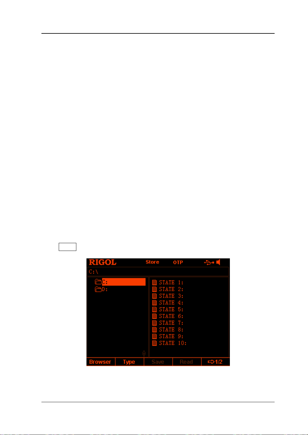
Chapter 2 Front Panel Operations RIGOL
Store and Recall
DP800 allows users to store v arious kinds of files in internal or external me mor y and
recall the files stored when required.
DP800 provides an interna l non-volatile memory (C disk) and an external memory (D
disk, only available when a USB storage device is detected at the USB HOST interface
at the rear panel).
1. C Disk
Provide 10 state fi le storage lo cations ( STATE 1 to STATE 10), 10 record fil e
storage locations (REC 1 to REC 10), 10 timer file storage locations (TIMER 1 to
TIMER 10) and 10 delay file storage locations (DELAY 1 and DELAY 10). Users
can store the state file, record file, timer file and delay file in C disk.
2. D Disk
Only available when a USB stor age device is detected at the USB HOST interface
at the rear panel. Users can store state file, record file, timer file and delay file in
the USB storage device and copy the files in C disk to the USB storage device.
The number of files can be stored depends on the storage space of the USB
storage device.
Besides, you can store the specified BMP file in a USB storage device and define
the start-up interface according t o the intro duction i n "User-defined Start-up
Interface
Press Store at the front panel to enter the interface as shown in the figure below.
".
Figure 2-10 Store and Recall Interface
DP800 User’s Guide 2-45
Page 96

RIGOL Chapter 2 Front Panel Operations
Browser
Press Store Browser to move the cursor to the directory or file area and then
use the knob or the up/down direction key to select the desired directory or file.
File Type
Press Store Type to select the desired file type (including state file, record file,
timer file, delay file, bitmap file and all files).
1. State File
Store the current instrument state (such as the parameter setting and system
state) in "*.RSF" format in internal or external memory. At most 10 instrument
states can be stored in the internal memory.
2. Record File
When the recorder is turned on, the instrument records the current output state
of each channel (such as the output voltage, current and power as well as
sample interval) and store them in "*.ROF" format in internal or external
memory w hen the recorder is t urned off. At most 10 reco rd files can be s tore d in
the internal memory.
3. Timer File
Store the edited timer parameters (the voltage, current and time values) in
"*.RTF" format in internal or external memory. At most 10 timer files can be
stored in the internal memory.
4. Delay File
Store the edited delay parameters (the states an d time values) in "*.RDF"
format in internal o r external memory. At most 10 delay files can be stored in the
internal memory.
5. Bitmap File
You ca n b r ows e the "*.BMP" format bitmap files under the current directo ry. As
"*.BMP" format bitmap files cannot be stored in C disk, the right side of the
store and recall interface is blank when the file type is set to "*.bmp" and the
current directory is C disk.
6. All File
Display all the files and folders un der the directory currently selected. Whe n th is
menu is selected, the save operation is not available.
2-46 DP800 User’s Guide
Page 97
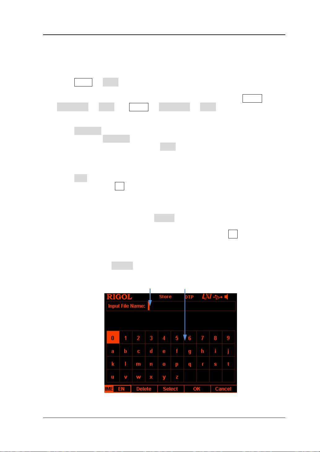
Chapter 2 Front Panel Operations RIGOL
Filename Input Area Virtual Keyboard
Save
You can save a file following the steps below.
1. Press Store Type to select the desired file type.
Note: The save operation is available only when the file type is "*.rsf". The
timer file and the delay file can be saved separately by pressing Timer
Timer Set Save and Timer Delay Set Save and the record file is
saved automatically in the specified path when you turn off the recorder.
2. Press Browser to switch the cursor to the directory area to select the desired
directory. Press Browser again to switch the cursor to the file area and select
the desired storage directory. Press Save to open the f ilename input interface
Figure 2-11 or Figure 2-12).
(
3. Input the filename.
Press IME to select "CH" or "EN" in the filename input interface (Figure 2-11 or
Figure 2-12
uppercase and lowercase.
English Input (include number input)
In English input method, use the knob to select the desired character in the
"Virtual Keyboard" and press Select to select this character; the character
selected is displayed in the "Filename Input Area". Use the same method to
input all the characters in the filename (you can press . to switch
between uppercase and lowercase if needed).
The length of the filename ca nnot exceed 9 characters. During the input,
you can press Delete to delete the character currently at the left of the
cursor in the "Filename Input Area".
). Press . on the numeric keyboard to switch between English
Figure 2-11 Filename Input Interface (English)
DP800 User’s Guide 2-47
Page 98
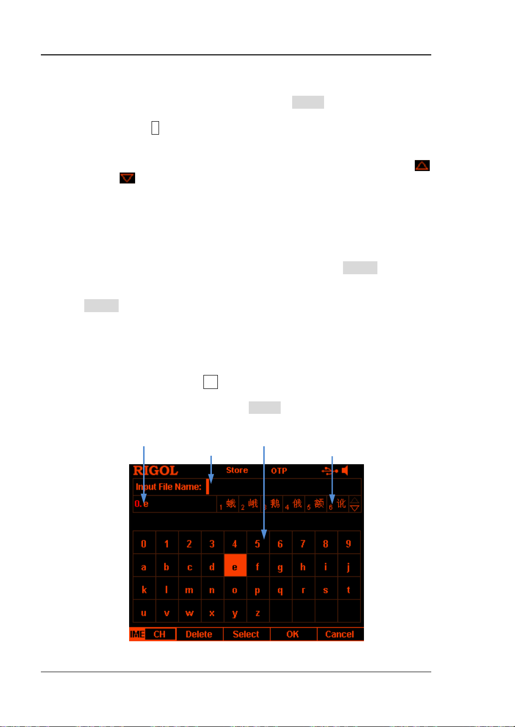
RIGOL Chapter 2 Front Panel Operations
Pinyin Input Area Virtual Keyboard
Chinese Input
In Chinese input method, use the knob to select the desired Pinyin
character in the "Virtual Ke yboard" and press Select to select this character;
the character selected is displayed in the "Pinyin Input Area" (at this point,
you can press 0 on the numeric keyboard to directly input the English
characters in the "Pinyin Input Area"). After inputting the pinyin of a
Chinese character, select the number of the desire d Chinese chara cter using
the numeric keyboard in the "Chinese Character Selection Area" (if the
or/and
icon at the right side of the "Chinese Character Selection Area"
is illuminated, you can use the up/down directio n key to turn to the
previous or next page) and the Chinese character selected is displayed in
the "Filename Input Area". Use the same method to input all the Chinese
characters in the filename.
The length of the filename cannot exceed 9 characters (a Chinese character
occupies 2 characters). During the input, you can press Delete
continuously to delete the characters in the "Pinyin I nput A rea" from right
to left if there are characters in the "Pinyin Input Area" or you can press
Delete to delete the Chinese chara cter currently at the left o f the cursor in
the "Filename Input Area" if there is not character in the "Pinyin Input
Area".
Note:
Chinese input is not supported in uppercase state. To use the Chinese
input method, press . to select lowercase state.
In Chinese input method, after a number in the "Virtual Keyboard" is
selected using the knob, press Select to select this number and the
number will be directly displayed in the "Filename Input A rea".
Filename Input Area Chinese Character Select ion Area
Figure 2-12 Filename Input Interface (Chinese)
2-48 DP800 User’s Guide
Page 99

Chapter 2 Front Panel Operations RIGOL
4. After inputting the f ilename in the filename input interface, press OK and the
instrument stores the file with the specified filename in the specified f ile type
under the storage directory currently selected. If the storage location selected
already contains a valid file, the instrument will p rompt whethe r to ove rwrite t he
original file and press OK to finish the save operation.
Read
You can read the specified type of file following the steps below.
1. Press Store Type to select the desired file type.
Note: The read operation is available only when the file type is "*.rsf" or "All
File". The timer file and delay file can be read separately by pressing Timer
Timer Set Read and Timer Delay Set Read and the record file can
be read by pressing Analyzer Open File.
2. Press Browser to switch the cursor to the directory area and select the
directory of the fi le to be read; press Browser again to switch to the file ar e a
and select the file to be read.
3. Press Read and the instrument read the file currently selected. If the current
location does not contain a v ali d file, the correspondi ng pr ompt messa ge will b e
displaye d. Fo r a state file, the instrument enters the main interface after the file
is successfully read; for other types of files, the instrument enters the
corresponding function interface after the file is successfully read.
Delete
You can delete the files under C disk and D disk as well as the empty f olders un der D
disk.
1. Press Store Browser to move the cursor to the directory area and select the
directory of the file to be deleted; press Browser a gain to switch t o the file area
and select the f ile or empty folder to be deleted.
2. Press Delete and the prompt message asking whether to delete the file or
empty folder currently selected is displayed. Press OK to finish the delete
operation.
DP800 User’s Guide 2-49
Page 100

RIGOL Chapter 2 Front Panel Operations
Copy and Paste
You can only copy the files in C disk and paste the files to D di sk.
1. Press Store Browser to move the cursor to the directory area and select C
disk; press Browser again to switch to the file area and select the file to be
copied.
2. Press Copy and the instrument copies the file currently selected.
3. Press Browser to switch to the directory area and select D disk.
4. Press Paste, the instrument pastes the file copied to the D disk and the
correspondin g prom pt message is displayed when th e file is successfully pasted.
2-50 DP800 User’s Guide
 Loading...