

Page 1

RIGOL
Quick Guide
DP800 Series Programmable
Linear DC Power Supply
Mar. 2015
RIGOL Technologies, Inc.
Page 2

Page 3

RIGOL
Guaranty and Declaration
Copyright
© 2012 RIGOL Technologies, Inc. All Rights Reserved.
Trademark Information
RIGOL is a registered trademark of RIGOL Technologies, Inc.
Publication Number
QGH04104-1110
Notices
RIGOL products are covered by P. R.C. and fo reign pat ents, issued and pendin g.
RIGOL reserves the right to modify or change parts of or all the specifications
and pricing policies at company’s sole decision.
Information in this publication replaces all previously corresponding mate ri a l.
Information in this publication is subject to change without notice.
RIGOL shall not be liable for either incidental or consequential losses in
connection with the furnishing, use or performance of this manual as well as any
information contained.
Any part of this document is forbidden to be copi e d, ph otoc o pie d or rearranged
without prior written approval of RIGOL.
Product Certification
RIGOL guar antees this pr oduct confo rms to the national and industrial stan dar ds in
China as well as the ISO9001:2008 standard and the ISO14001:2004 standard.
Other international standard conformance certif ication is in progress.
Contact Us
If you have any problem or requirement when using our products or this manual,
please contact RIGOL.
E-mail: [email protected]
Website: www.rigol.com
DP800 Quick Guide I
Page 4

RIGOL
Safety Requirement
General Safety Summary
Please review the following safety precautions carefully before putting the
instrument into operation so as to avoid any personal injury or damage to the
instrument and any product connecte d to it. To prevent potential hazards, please use
the instrument only specified by this manual.
Use Proper Power Cord.
Only the power cord designed for the instrument and authorized for use within the
local country could be used.
Ground the Instrument.
The instrument is grounded through the Protective Earth lead of the power cord. To
avoid electric shock, it is e ssential t o connect the ea rth terminal of the power cord to
the Protective Earth terminal before connecting any inputs or outputs.
Connect the Probe Correctly.
If a probe is used, do not connect the ground lead to high vol tage since it has
isobaric electric potential as the ground.
Observe All Terminal Ratings.
To avoid fire or shock hazard, obse rve all ratings and ma rkers on the ins trument and
check your manual for more information about ratings before connecting the
instrument.
Use Proper Overvoltage Protection.
Make sure that no overvoltage (such as that caused by a thunderstorm) can reach
the product, or else the operator might be exposed to the danger of electrical shock .
Do Not Operate Without Covers.
Do not operate the instrument with covers or panels removed.
Do Not Insert Anything Into the Holes of Fan.
Do not insert anything into the holes of the fan to avoid damaging the instrument.
Use Proper Fuse.
Please use the specified fuses.
Avoid Circuit or Wire Exposure.
Do not touch exposed junctions and components when the unit is powered.
II DP800 Quick Guide
Page 5

RIGOL
Do Not Operate With Suspected Failures.
If yo u suspect damage occurs to the instrument, have it inspected by RIGOL
authorized personnel before further oper at io ns. Any maintenance, adjustment or
replacement especially to circuits or accessories must be performed by RIGOL
authorized personnel.
Keep Well Ventilation.
Inadequate ventilation may cause an increase of instrument temperature which
would cause damage to the instrument. So please keep the instrument well
ventilated and inspect the intake and fan regularly.
Do Not Operate in Wet Conditions.
In order to avoid short circuiting t o the interi or of the device or electric s hock, please
do not operate the instrument in a humid environment.
Do Not Operate in an Explosive Atmosphere.
In order to avoid damage to the device or persona l injuries, it is im portant to operate
the device away fr om an expl osive atmosphere.
Keep Product Surfaces Clean and Dry.
To avoid the influence of dust and/or moisture in the air, please keep the surface of
the device clean and dry.
Electrostatic Prevention.
Operate the instrument in an electrostatic discharge p rotective en vironment to av oid
damage induced by static discharges. Always ground both the internal and external
conductors of cables to release static before making connections.
Proper Use of Battery.
If a battery is supplied, it must not be exposed to high temperature or in contact with
fire. Keep it out of the reach of children. Improper change of battery (note: lithium
battery) may cause explosion. Use RIGOL specified battery only.
Handling Safety.
Please handle with care during transportation to avoid damage to buttons, knob
interfaces and other parts on the panels.
Do Not Provide Power for the Active Load.
In order to avoid the anti-irrigation current which leads to the power control loop out
of control and damages the powered device, this power supply can only provide
power for the pure load without the current output function.
DP800 Quick Guide III
Page 6
RIGOL
WARNING
injury or loss of life.
CAUTION
damage to this product or other property.
DANGER
It calls attention to an operation, if not correctly pe rformed, could
result in injury or hazard immediately.
WARNING
It calls attention to an operation, if not correctly pe rformed, could
result in potential injury or hazard.
CAUTION
It calls attention to an operation, if not correctl y pe rformed, could
product.
Hazardous
Safety
Protective
Terminal
Chassis
Test
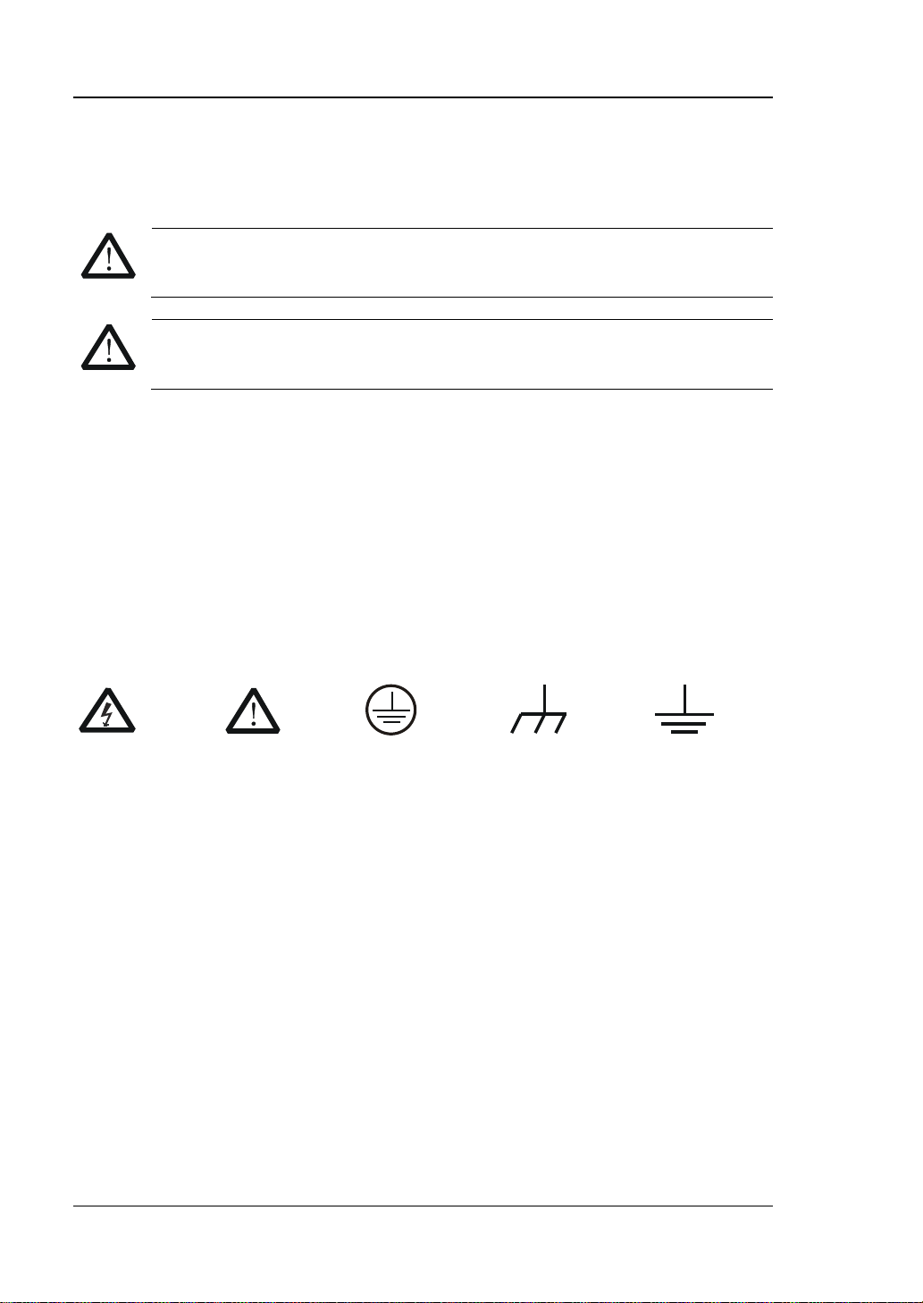
Safety Terms and Symbols
Terms Used in this Manual. These terms may appear in this manual:
Warning statements indicate conditions or practices that could result in
Caution statements indicate conditions or practices that could result in
Terms Used on the Product. These terms may appear on the product:
result in damage to the product or other devices connected to the
Symbols Used on the Product. These symbols may appear on the product:
Voltage
Warning
Earth
Ground
Ground
IV DP800 Quick Guide
Page 7

RIGOL
Allgemeine Sicherheits Informationen
Überprüfen Sie diefolgenden Sicherheitshinweise
sorgfältigumPersonenschädenoderSchäden am Gerätundan damit verbundenen
weiteren Gerätenzu vermeiden. Zur Vermeidung vonGe fahren, nutz en Sie bitte das
Gerät nur so, wiein diesem Handbuchangegeben.
Um Feuer oder Verletzungen zu vermeiden, verwenden Sie ein
ordnungsgemäßes Netzkabel.
Verwenden Sie für dieses Gerät nur das für ihr Land zugelass ene u nd genehm igte
Netzkabel.
Erden des Gerätes.
Das Gerät ist durch den Schutzleiter im Netzkabel geerdet. Um Gefahren durch
elektrischen Schlag zu vermeiden , ist es unerlässlich, die Er dung durchzufüh ren. Erst
dann dürfen weitere Ein- oder Aus gä nge verbunden werden.
Anschluss einesTastkopfes.
Die Erdungsklemmen der Sonden sindauf dem gleichen Spannungspegel des
Instruments geerdet. SchließenSie die Erdungsklemmen an keine hohe Spannung
an.
Beachten Sie alle Anschlüsse.
Zur Ve rm e idung von Feuer oder Stromschlag, beachten Sie alle Bemerkungen und
Markierungen auf dem Instrument. Bef olgen Sie die Bedienun gsanleitung für weitere
Informationen, bevor Sie weitere Anschlüsse an das Instrument legen.
Verwenden Sie einen geeigneten Überspannungsschutz.
Stellen Sie sicher, daß keinerlei Überspannung (wie z.B. du rc h Gewitter verursacht)
das Gerät erreichen kann. Andernfallsbestehtfür den Anwender die
GefahreinesStromschlages.
Nicht ohne Abdeckung einschalten.
Betreiben Sie das Gerät nicht mit entfernten Gehäuse-Abdeckungen.
Betreiben Sie das Gerät nicht geöffnet.
Der Betrieb mit offenen oder entfernten Gehäuseteilen ist nicht zulässig. Nichts in
entsprechende Öffnungen stecken (Lüfter z.B.)
Passende Sicherung verwenden.
Setzen Sie nur die spezifikationsgemäßen Sicherungen ein.
Vermeiden Sie ungeschützte Verbindungen.
Berühren Sie keine unisolierten Verbindungen oder Baugruppen, während das Gerät
in Betrieb ist.
DP800 Quick Guide V
Page 8

RIGOL
Betreiben Sie das Gerät nic h t i m Fehlerfall.
Wenn Sie am Gerät einen Defekt vermuten, sorgen Sie dafür, bevor Sie das Gerät
wieder betreiben, dass eine Untersuchung durch RIGOL autorisiertem Personal
durchgeführt wird. Jedwede W artun g, Einstellarbeit en oder Austausch v on Teilen am
Gerät, sowie am Zubehör dürfen nur von RIGOL autorisiertem Personal
durchgeführt werden.
Belüftung sicherstellen.
Unzureichende Belüftung kann zu Temperaturanstiegen und somit zu thermischen
Schäden am Gerät führen. Stellen Sie deswegen die Belüftung sicher und
kontrollieren regelmäßig Lüfter und Belüftungsöffnungen.
Nicht in feuchter Umgebung betreiben.
Zur Vermeidun g von Kurzschluß im Geräteinne ren und Stromschlag betreiben Sie das
Gerät bitte niemals in feuchter Umgebung.
Nicht in explosiver Atmosphäre betreiben.
Zur Ve rm e idung von Pers onen- und Sachschäden ist es unumgänglich, das Gerät
ausschließlich fernab jedweder explosiven At mos phäre zu betreiben.
Geräteoberflächen sauber und trocken halten.
Um den Einfluß von Staub und Feuchtigkeit aus der Luft auszuschließen, halten Sie
bitte die Geräteoberflächen sauber und trocken.
Schutz gegen elektrostatische Entladung (ESD).
Sorgen Sie für eine elektrostatisch geschützte Umgebung, um somit Schäden und
Funktionsstörungen durch ESD zu vermeiden. Erden Sie vor dem Anschluß immer
Innen- und Außenleiter der V erbindungsleitung, um st atische Aufladung zu entladen.
Die richtige Verwendung desAkku.
Wenneine Batterieverwendet wird, vermeiden Sie hohe Temperaturen bzw. Feuer
ausgesetzt werden. Bewahren Sie es außerhalbder Reichweitevon Kindern auf.
Unsachgemäße Änderung derBatte ri e (Anmerkung: Lithium-Batterie) kann zu einer
Explosion führen. VerwendenSie nur von RIGOL angegebenenAkkus.
Sicherer Transport.
Transportieren Sie das Gerät sorgfältig (Verpackung!), um Schäden an
Bedienelementen, Anschlüssen und anderen Teilen zu vermeiden.
Vermeiden Sie das einprägen von Strom und Spannung an den
Testklemmen.
Das DP800 Power Supply kann hierdurch zerstört werden , k eine akive Last. Das
DP800 kann nur Strom und Spannungen leifern.
VI DP800 Quick Guide
Page 9
RIGOL
WARNING
Schäden oder den Tod von Personen zur Folge haben können.
CAUTION
Schäden am Gerät hervorrufen können.
DANGER
weist auf eine Verletzung ode r Gefäh r dun g hin, die sof ort
geschehen kann.
WARNING
weist auf eine Verletzung oder Gefäh rdung hin, die möglicherweise
nicht sofort geschehen.
CAUTION
weist auf eine Verletzun g ode r Gefährdung hin und bedeutet, dass
Gegenstände auftreten kann.
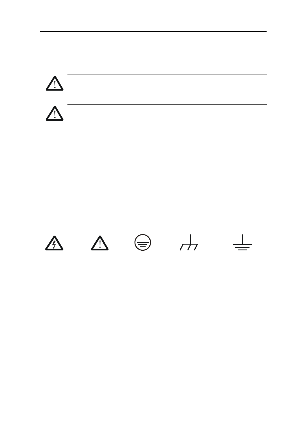
Sicherheits Begriffe und Symbole
Begriffe in diesem Guide. Diese Begriffe können in diesem Handbuch auftauchen:
Die Kennzeichnung WARNING beschreibt Gefahrenquellen die leibliche
Die Kennzeichnung Caution (Vorsicht) beschreibt Gefahrenquellen die
Begriffe auf dem Produkt. Diese Bedingungen können auf dem Produkt
erscheinen:
eine mögliche Beschädigung des Instruments oder anderer
Symbole auf dem Produkt. Diese Symbole können auf dem Produkt erscheinen:
Gefährliche
Spannung
SicherheitsHinweis
Schutz-erde Gehäusemasse Erde
DP800 Quick Guide VII
Page 10
RIGOL
CAUTION
WARNING
supply.
General Care and Cleaning
General Care
Do not store or leave the instrument where it may be exposed to direct sunlight for
long periods of time.
Cleaning
Clean the instrument regularly according to its operating conditions. To clean the
exterior surface, perform the following steps:
1. Disconnect the instrument from all power sources.
2. Clean the loose dust on the outside of the i nstrument with a lint -free cloth (with
a mild detergent or water). When cleaning the LCD, take care to av oid sca rifying
it.
To avoid damage to the instrument, do not expose it to caustic liquids.
To avoid short-circuit and personal injury resulting from moisture, make
sure the instrument is completely dry before reconnecting it to power
Environmental Consideratio ns
The following symbol indicates that this product complies with the requirements in
WEEE Directive 2002/96/EC.
Product End-of-Life Handling
The equipment may contain substances that could b e harmf ul t o the envi ronm ent or
human health. In order to avoid release of such substances into the environment and
harm to human health, we encourage you to recycle this product in an appropriate
system that will ensure that most of the materials are reused or recycled
appropriately. Please contact your local authorities for disposal or recycling
information.
VIII DP800 Quick Guide
Page 11
RIGOL
Model
Number of Channels
Channel Output Voltage/Current
DP832
3
30V/3A, 30V/3A, 5V/3A
DP831
3
8V/5A, 30V/2A, -30V/2A
DP821
2
60V/1A, 8V/10A
DP811
1
Range1: 20V/10A; Range2: 40V/5A
Document Overview
This manual is used to gui de use rs to qui ckly unders tand the f ront panel, rear panel,
user interface and basic o perating methods of DP800 series progr ammable lin ear DC
power supply. You can download the newest version of this manual from RIGOL
official website (
Format Conventions in this Manual
1. Button
The function key at the front panel is denoted by the format of “Button Name
(Bold) + Text Box” in the manual , for e xample, Utility denotes the “Utility” key.
2. Menu
(1) The menu item can be denoted by the format of “Menu Word (Bold) +
Character Shading”, for example, SysInfo denotes the “SysInfo” menu item
under Utility.
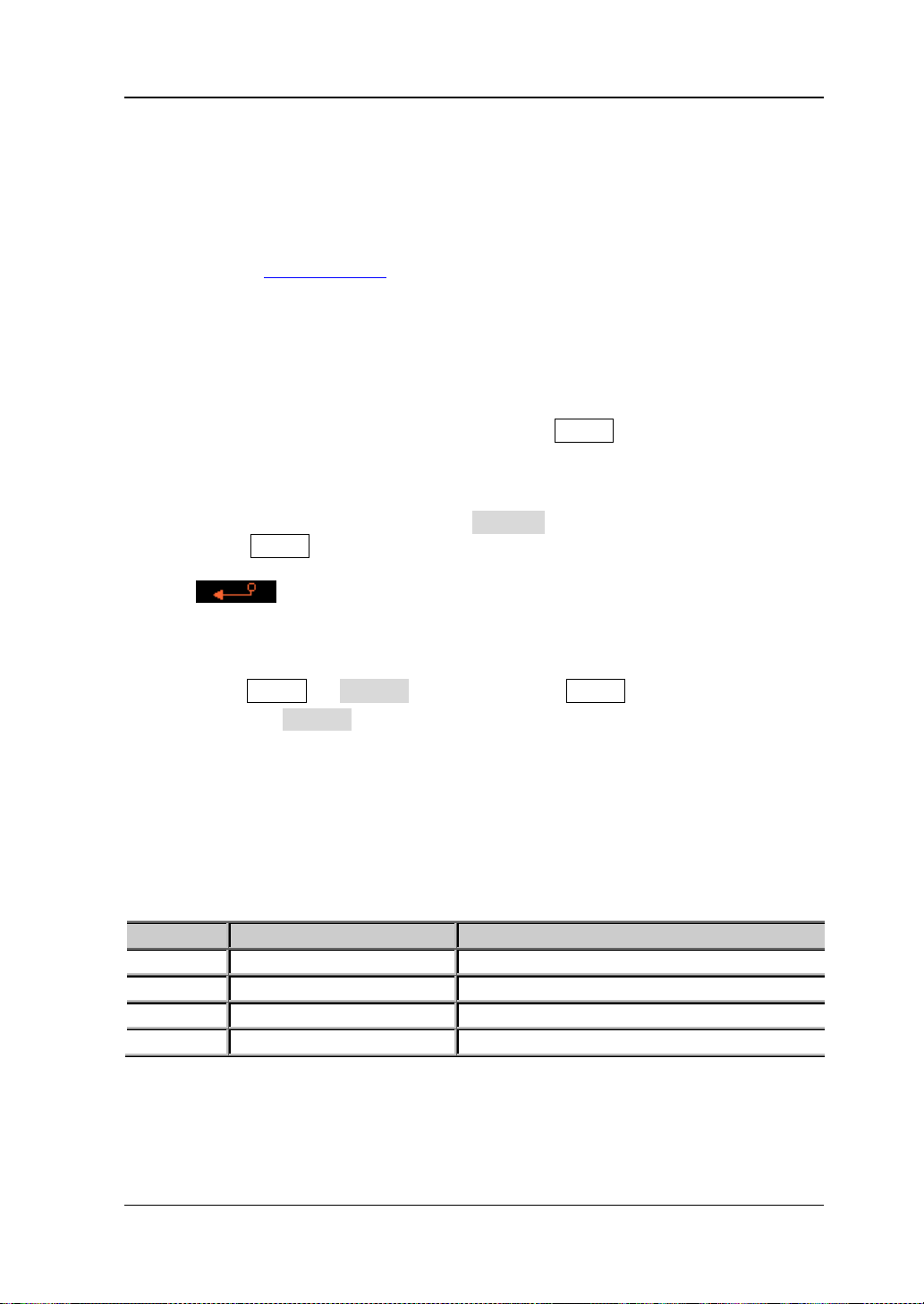
(2) The menu item can be denote by the screenshot of the menu, for example,
3. Operation Step
The next step of the operation is denoted by an arrow “” in the manual. For
example, Utility System de notes pressing Utility at the front panel and
then pressing System.
Content Conventions in this Manual
DP800 series programmable linear DC power supply includes the following models.
Unless otherwise noted, this manual illustra tes DP800 se ries an d its basic operations
by taking DP832 as an example.
www.rigol.com).
.
DP800 Quick Guide IX
Page 12

RIGOL
Contents
Guaranty and Declaration ......................................................................... I
Safety Requirement ................................................................................. II
General Safety Summary........................................................................... II
Safety Terms and Symbols ....................................................................... IV
Allgemeine Sicherheits Informationen ........................................................ V
Sicherheits Begriffe und Symbole ............................................................. VII
General Care and Cleaning ..................................................................... VIII
Environmental Considerations ................................................................. VIII
Document Overview ............................................................................... IX
Quick Start ............................................................................................... 1
General Inspection .................................................................................... 1
Appearance and Dim e nsions ...................................................................... 2
Front Panel ............................................................................................... 3
Rear Panel .............................................................................................. 10
To Connect to Power ............................................................................... 12
Power-on Inspection ................................................................................ 13
To Replace the Fuse ................................................................................ 13
User Interface ......................................................................................... 14
To Use the Built-in Help System ................................................................ 16
Troubleshooting ..................................................................................... 17
X DP800 Quick Guide
Page 13

RIGOL
Quick Start
General Inspection
1. Inspect the shipping container for damage
Keep the damaged shipping container or cushioning material until the contents
of the shipment have been checked for completeness and the instrument has
passed both ele ctrica l a nd mechanical tests.
The consigner or carrier shall be liable for the damage to instrument resulting
from shipment. RIGOL woul d n ot be responsible for free maintenance/rework
or replacement of the unit.
2. Inspect the instrument
In case of any damage, or defect, or failure, notify your RIGOL sales
representative.
3. Check the accessories
Please check the accessories according to the packi ng l is t s. If t he accessories
are incomplete or damaged, please contact your RIGOL sales representative.
DP800 Quick Guide 1
Page 14
RIGOL
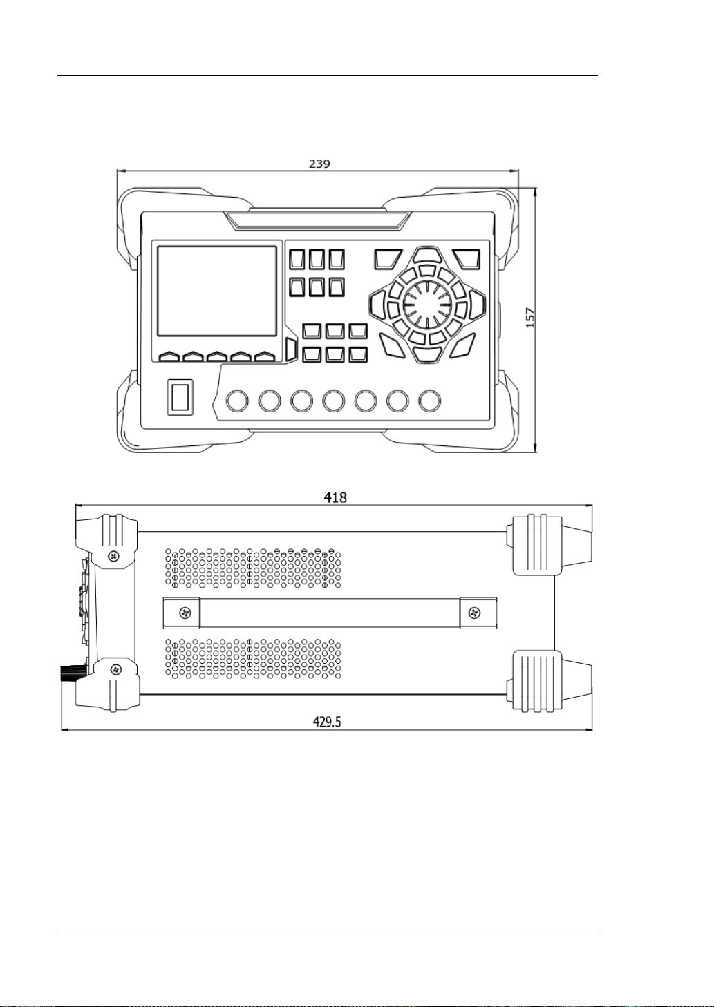
Appearance and Dimensions
Figure 1 Front View Unit: mm
Figure 2 Side View Unit: mm
2 DP800 Quick Guide
Page 15
RIGOL
1 2 3 4
11 10 9 8 7 6 5
Front Panel
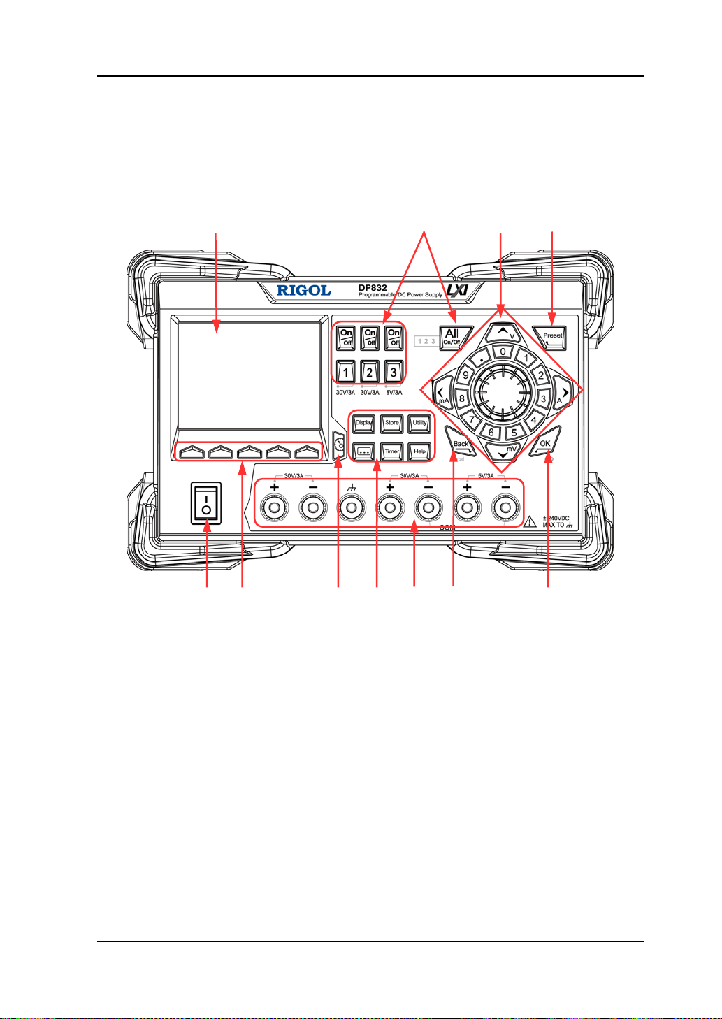
This section introduces the front panel of DP800 serie s by takin g DP832 (as sh own in
the figure below) as an example. The differences of different models are introduced
separately.
Figure 3 DP832 Front Panel
DP800 Quick Guide 3
Page 16
RIGOL
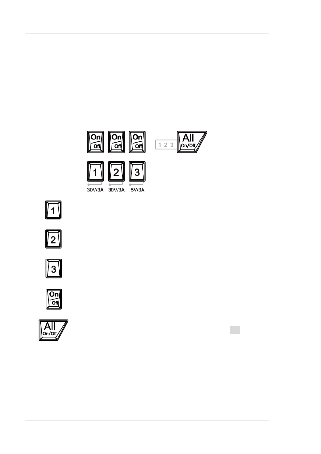
Press this key to select CH 1 as the c urrent channel a nd y ou can set
Press this key to select CH 2 as the c urrent channel a nd y ou can set
Press this key to sele ct CH 3 as t he cu rrent channel and you can set
Press this key to enable or disable the output of the corresponding
Press this key and the prompt message asking whether to enable
the outputs of all the channels.
1. LCD
3.5 inches TFT display. It is used to display system parameter settings, system
output state, menu options, prompt messages, etc.
2. Channel (Range) Selection and Output Switch
For the multi-channel model, the function of this part is channel selection and
output switch. For the single-channel model, the function of this part is range
selection and output switch.
Multi-channel models (take DP832 as an example):
the parameters of this channel, such as voltage, current and
overvoltage/overcurren t protection.
the parameters of this channel, such as voltage, current and
overvoltage/overcurren t protection.
the parameters of this channel, such as voltage, current and
overvoltage/overcurren t protection.
channel.
the outputs of all the channels will be dis played. Pres s OK to enable
the outputs of all the channels. Pressing this key again will disable
4 DP800 Quick Guide
Page 17
RIGOL
20V
10A
40V
5A
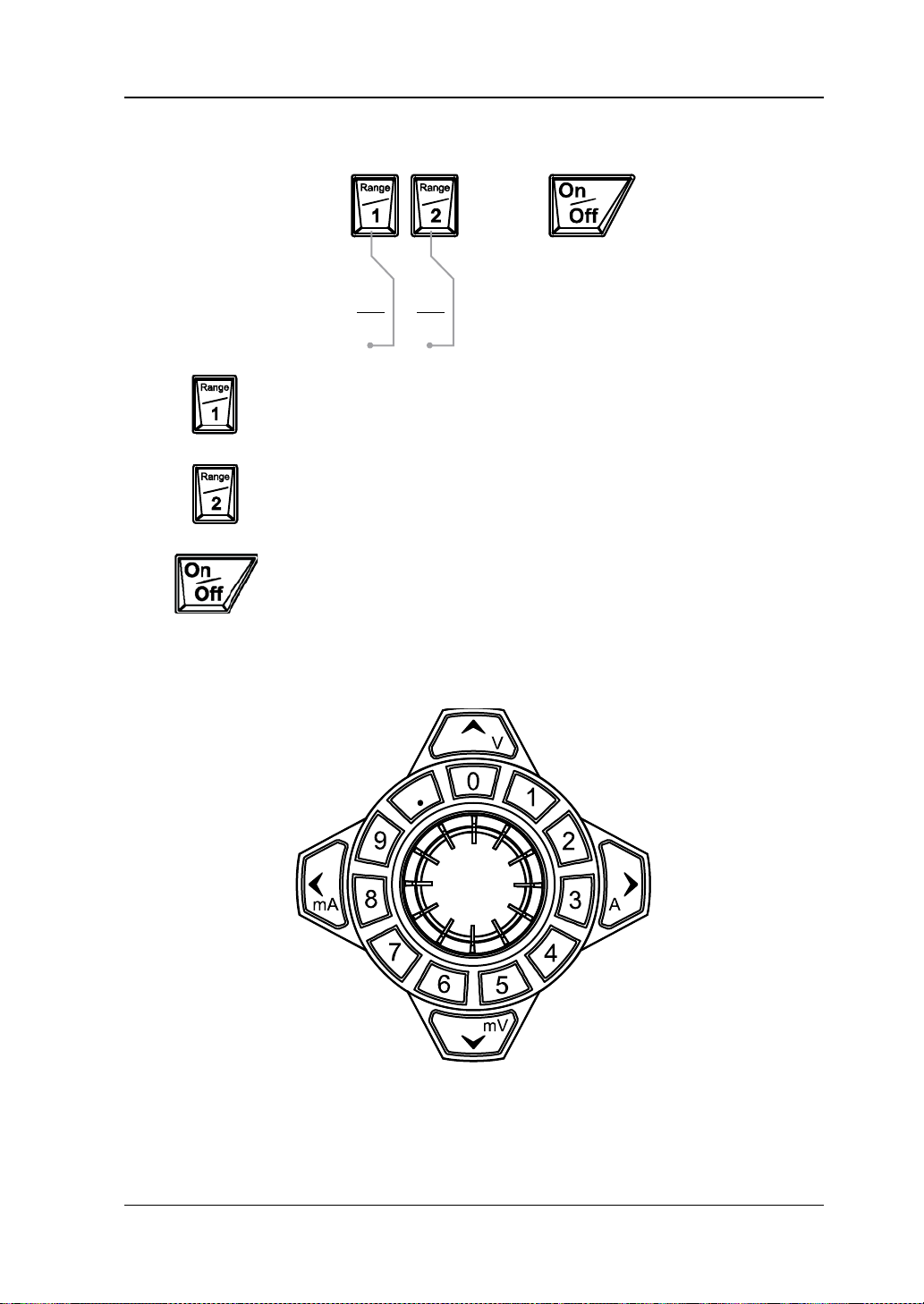
Press this key to select 20V/10A range as the current range and
Press this key to select 40V/5A range as the current range and you
Press this key to enable or disable the output of the channel.
Single-channel model (DP811):
you can set the parameters of the channel, such as voltage,
current and overvoltage/overcurrent protection.
can set the parameters of the channel, such as voltage, current
and overvoltage/overcurrent protection.
3. Parameter In p ut Area
The parameter input area is as shown in the figure below. This area in cludes the
direction keys (unit selection keys), numeric keyboard and knob.
(1) Direction keys and unit selection keys
Direction keys: used to move the cursor. When setting parameters, use the
up/down direction key to increase or reduce the value at the cursor.
DP800 Quick Guide 5
Page 18
RIGOL
Restore all the settings of the instrume nt to default values or recall
Confirm the parameter setting.
keyboard lock password is disabled, press and hold this key
(2012) to unlock the front panel keys.
Delete the character currently before the cursor.
Unit selection keys: whe n usi ng the nume ric ke yboa rd t o i nput par ameters ,
the keys are use d to e nter the v oltage units (V and mV) or the current units
(A and mA).
(2) Numeric Keyboard
Ring-type numeric keyboard: include numbers 0-9 and the decimal point.
Press the corresponding key to input the number or decimal point .
(3) Knob
When setting parameters, rotate the knob to increase or reduce the value at
the cursor.
When browsing the setting objects (timing parameters, delay parameters,
filename input, etc), rotate the knob to quickly move the cursor.
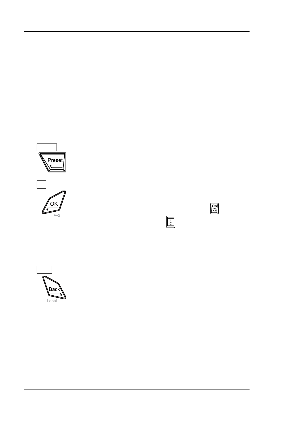
4. Preset
the user-defined channel voltage/current configurations.
5. OK
Press and hold this k ey to lock the front panel keys; at this point,
the front panel keys (except the output on/off key
channel and the power switch k ey
the
again to unlock the front panel keys. When the keyboard lock
password is enabled, you need to input the correct password
6. Back
When the instrument is in remote mode, p ress this k ey to return
to local mode.
of each
) are not availa ble. When
6 DP800 Quick Guide
Page 19
RIGOL
8V/10A60V/1A
S S
Output
(1)
(3)
(1) (2)
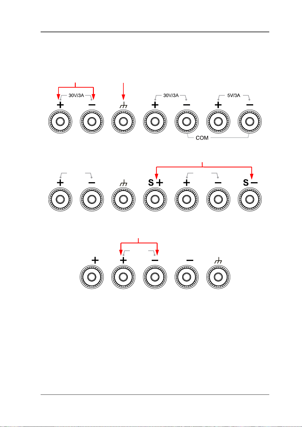
7. Output Terminals
The output terminals of different models of DP800 series are different.
DP832:
DP821:
DP811:
(1) Channel output terminals: used to output the voltage and current of the
channel.
(2) Ground terminal: this terminal is connected to the instrument chassis and
ground wire (the ground terminal of the power cord) and is in grounded
state.
(3) Sense terminals: used to detect the actual v oltage at the load ter minal so as
to compensate for the voltage dr op caused by the load lead.
DP800 Quick Guide 7
Page 20
RIGOL
Press this key to enter the display parameter setting interface.
interface.
and recall.
A
B
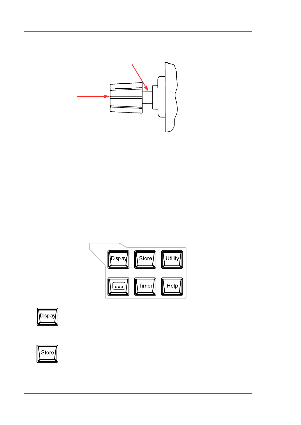
Connection methods of the output terminal:
Method 1:
Connect the test lead to A of the output terminal.
Method 2:
Rotate the outer nut of the output terminal counterclockwise and connect the
test lead to B of the output terminal; then, rotate the outer nut of the output
terminal clockwise. This connection method can eliminate the error caused by
the resistance of the output terminal.
Note: Connect the posit ive terminal of the test lea d wi th the (+) terminal of the
channel output and connect the negative terminal of the test lead with the (-)
terminal of the channel output.
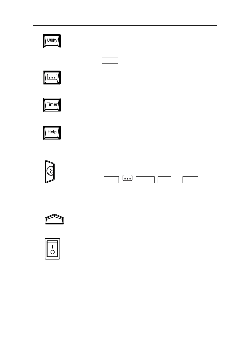
8. Function Menu Area
Users can set the brightness, contrast, RGB luminance, display
mode and display theme. Besides, you can also define the start-up
Press this key to enter the file store and recall interface. Yo u can
save, read, delete, copy and paste files. The file types available for
storage include state file, record file, timer file, delay file and
bitmap file. The instrument supports internal and external storage
8 DP800 Quick Guide
Page 21
RIGOL
Press this key to enter the system utility function setting interface.
configuration of Preset and install options.
Users can set t h e recorder, analyzer (option), monit or (option) and
Switch between the current display mode and dial display mode.
Users can set the remote interface parameters, system parameters
and print parameters. Besides, users can also calibrate the
instrument, view system information, define the recall
Press this key to enter the advanced function setting interface.
trigger (opti on ) parameters.
Press this key to enter the timer and delayer interface. Users can
set the timer and delayer parameters as well as enable and disable
the timer and delayer functions.
Press this key to open the built-in help system and press the
desired key to get the corresponding help information. F or detailed
introductions, refer to “To Use the Built-in Help System”.
9. Display Mode Switch Key
Besides, when the instrument is in a function interface (any
interface under Timer,
, Display, Store and Utility),
press this key to exit the f unction interf ace and return to the main
interface.
10. Me nu Keys
The menu keys correspond to the menus above them. Pres s a n y
menu key to selec t the correspondi ng menu.
11. Power Switch Key
Turn on or off the instrument.
DP800 Quick Guide 9
Page 22
RIGOL
T6
.3A
T
3.1
5A
AC
100
V
AC 115V
AC
230V
500
VA
O
p
t
.
Opt. Opt.
T6
.3A
T3.15
A
AC 100V
AC 115V
AC 230V
500VA
Opt. O
p
t.
O
pt.
S
S+
1 2 3 4 5 6
10 9 8 7
11
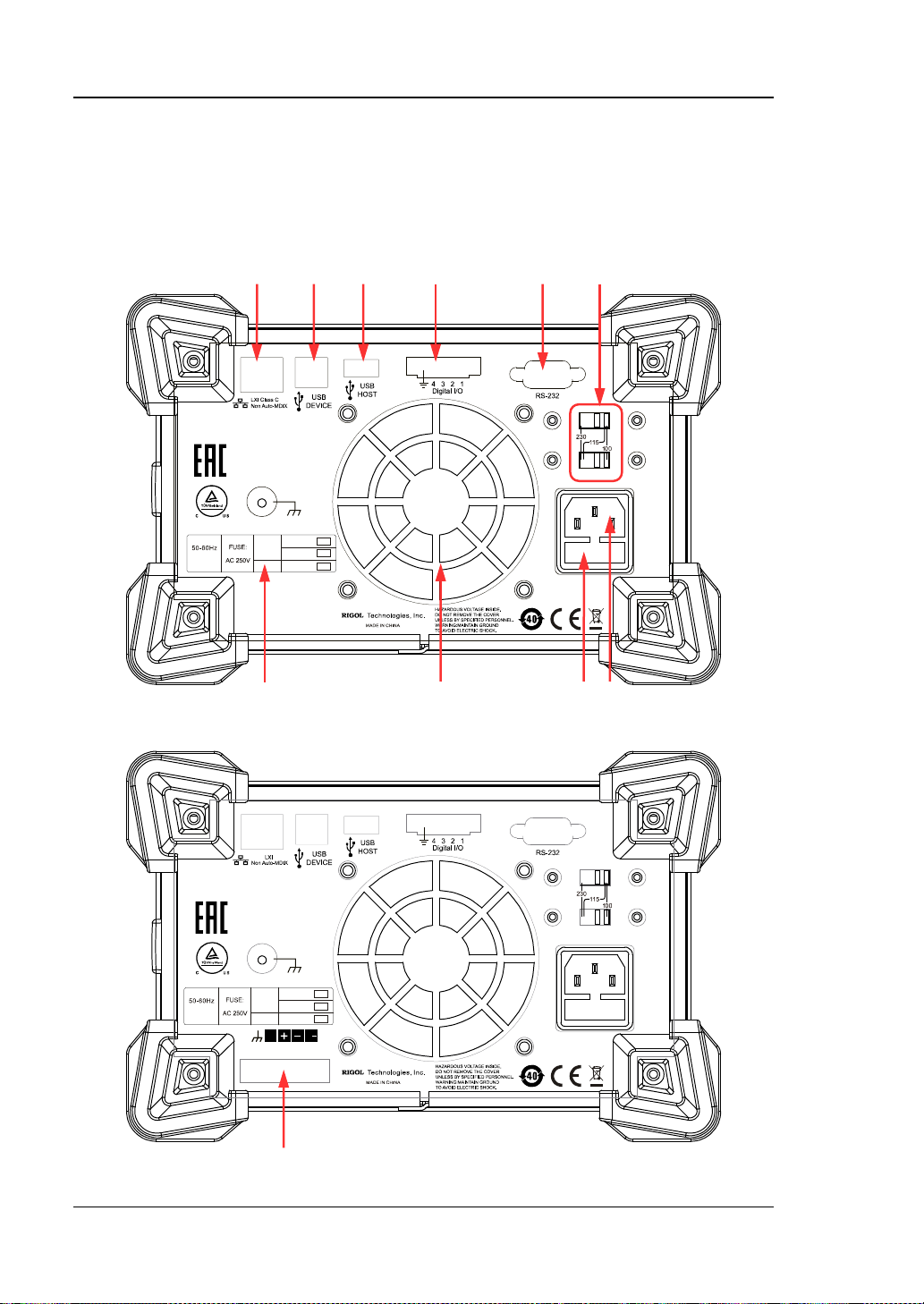
Rear Panel
This section introduces the rear panel of DP800 series by taking DP832 and DP811
(as shown in the figures below) as examples. The introduction of each part is as
shown in Table 1.
Figure 4 DP832 Rear Panel
10 DP800 Quick Guide
Figure 5 DP811 Rear Panel
Page 23
RIGOL
No.
Name
Explanation
4
Digital I/O (option)
Digital I/O interface
7
Power Socket
AC power input interface
9
Fan
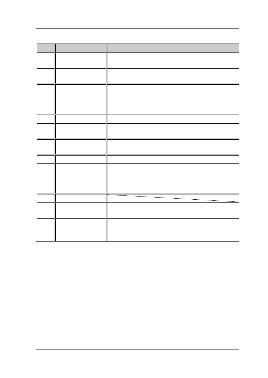
Table 1 DP800 Rear Panel Explanation
1
LAN Interf ace
(option)
2 USB DEVICE
3 USB HOST
5
RS232 Interface
(option)
6 Voltage Selector
8 Fuse
10
Input Power
Requirement
Connect to the local network via the RJ45 interface
Connect the instrument (as “slave device”) to
external USB device (such as, PC)
Connect the instrument (as “host device”) to external
USB device (such as, USB storage device);
extend a GPIB interface for the power supply using
USB-GPIB interface converter (option)
Serial communication interface
Select the specification of the input voltage (100, 115
or 230; please refer to Table 2)
The specification of the fuse is related to the
instrument model and actual input voltage (please
refer to the “Input Power Requirements” at the rear
panel of the instrument or refer to Table 3).
Corresponding relations of the AC input power
frequency, voltage and the specification of the fuse.
Only DP811 provides this interface. The function of
11 Output Interface
this interface is the same as that of the “Output
Terminals” at the front panel.
Note: The “Output Terminals” at the front panel and “Output Interface” at the rear
panel cannot be used for output at the same time. You can only select one of them
for output at each time (wherein, the output terminals at the front panel provide
higher output accuracy).
DP800 Quick Guide 11
Page 24
RIGOL
AC Input Power
Voltage Sele ctor Settin g
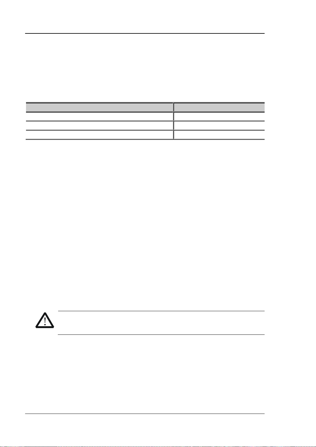
100Vac±10%, 50Hz to 60Hz
100
115Vac±10%, 50Hz to 60Hz
115
230Vac±10% (250Vac maximum ), 50Hz to 60Hz
230
WARNING
grounded.
To Connect to Power
DP800 series power supply supports various AC power supply inputs. The voltage
selector setting at the rear panel differs when the input power connected is different,
as shown in the table below.
Table 2 AC Input Power Specifications (including voltage selector settings)
Please connect the power following the steps below.
1. Check the input power
Make sure that the AC power to be connected to the instrument fulfills the
requirements in Table 2.
2. Check the voltage selector at the rear panel
Make sure that the v oltage selector setting (110, 115 or 230 ) at the rear panel of
the instrument matches the actual input voltage (for the matching relations,
refer to Table 2).
3. Check the fuse
When the instrument leav es f actory, the specified fuse is installed. Please chec k
whether the fuse matches the actual input voltage according to the “Input
Power R e quirements” at the rear panel of the instrument or Table 3.
4. Connect the AC power
Connect the instrument to AC power supply using the power cord provided in
the accessories.
To avoid electric shock, make sure that the instrument is correctly
12 DP800 Quick Guide
Page 25
RIGOL
Tip
Input Voltage
Fuse Specification
DP832/DP811
100Vac/115Vac
T6.3A
230Vac
T3.15A
DP831/DP821
100Vac/115Vac
T5A
230Vac
T2.5A
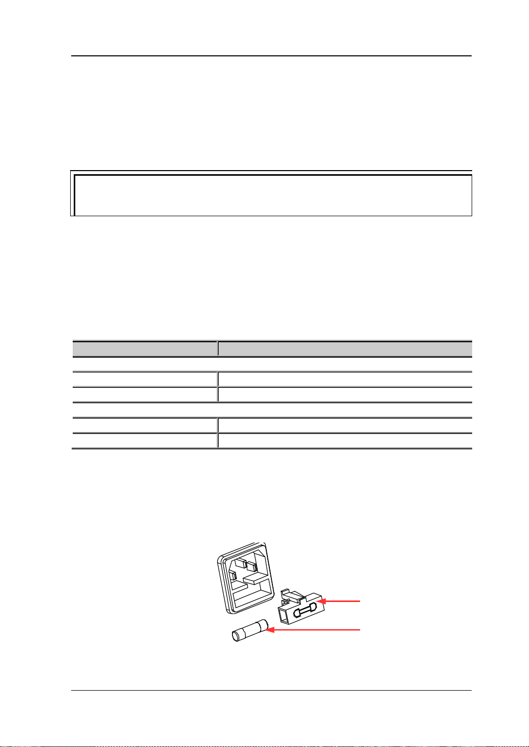
Fuse Seat
Power-on Inspection
Press the power switch at the front panel and the instrument executes self-test. If
the instrument passes the self-test, the welcome interface will be displayed;
otherwise, the corresponding self-test failure information (including TopBoard,
BottomBoard, Fan and Temperature) will be displayed.
When turn the instrument on again after turn it off, please make sure the time
between the two operations are larger than 5s.
To Replace the Fuse
The fuse specification is related to the instrument model and actual in put volt age, as
shown in the table below. You can also refer to the “Input Power Requirements” at
the rear panel of the instrument.
Table 3 Fuse Specifications
To replace the fuse, follow the steps below.
1. Turn off the instrument and remove the power cord.
2. Insert a small straight s crewdriver into the slot at the power s ocket and prize out
3. If needed, adjust the power v oltage selector manually to select the voltage scale
DP800 Quick Guide 13
the fuse seat gently.
Fuse
Page 26
RIGOL
WARNING
to this specification before connecting to power.
1 2 3 4 5
6
(please refer to Table 2) that matches the actual input voltage.
4. Take out the fuse and replace it with a specified one (please refer to the “Input
Power R e quirement” at the rear panel of the instrument or Table 3).
5. Re-insert the fuse seat into the power socket (pay attention to the direction).
To avoid personal injuries, cut off the power supply before re placing the
fuse; to avoid elect ric shock or fire, select the power supply specification
that matches the actual input voltage and replace a fuse corresponding
User Interface
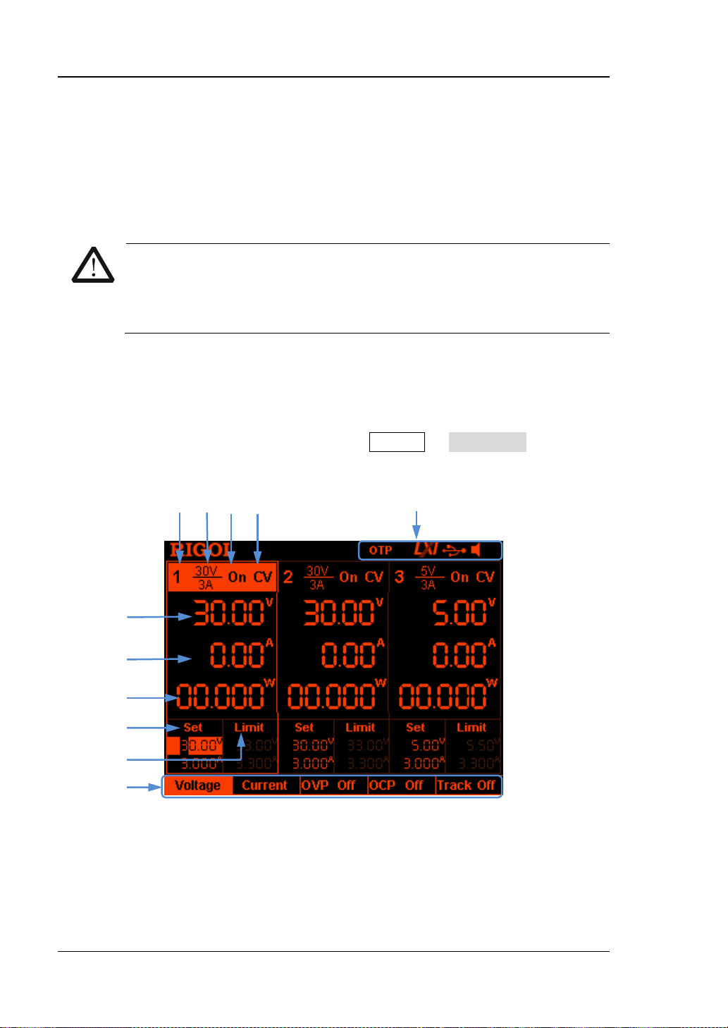
DP800 series po wer su pply provides three kinds of dis play m odes (normal , wa vef orm
and dial). The default is normal. You can press Display Disp Mode to select
different display mode. This section introduces the user interface layout under the
normal display mode (as shown in the figure below and
Table 4 on the next page).
7
8
9
10
11
Figure 6 User Interf a ce
14 DP800 Quick Guide
Page 27
RIGOL
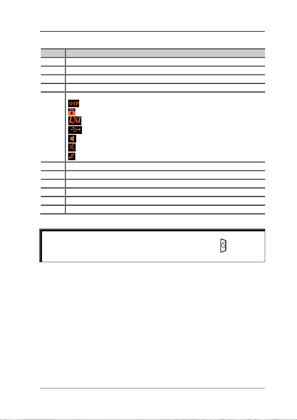
No.
Explanation
1
Channel Number
2
Channel Output Voltage/Current
3
Channel Output State
4
Channel Output Mode
5
Status Bar, display the system status labels.
: the instrument is working in remote mode.
6
Actual Output Voltage
7
Actual Output Current
8
Actual Output Power
9
Voltage and Current Setting Values
10
Overvoltage Protection and Overcurrent Protection Se tting Values
11
Menu Bar
Tip
panel to quickly switch between the current display mode and dial displa y mo de.
Table 4 User Interface Explanation
: over-temperature protection is enabled.
: the front panel is locked.
: the network is connected.
: the USB device is recognized.
: the beeper is enabled.
: the beeper is disabled.
When the current display mode is “Normal” or “Waveform”, press at the front
DP800 Quick Guide 15
Page 28

RIGOL
To Use the Built-in Help System
The built-in help s ystem provides help inf ormation for an y front panel key (except the
parameter input area) and menu keys for users to quickly obtain the function
prompts of the function keys or menus.
Obtain the help information of any key
Press Help to illuminate it and press the desired key or menu key to g et the
corresponding help information; at the same time, the backlight of Help goes off.
You can press to exit the help system.
Built-in help interface
Press Help to illuminate it and press Help again to ope n the built-in help interface.
Use the up/down direction key or knob to select the desired help topic and press
View to view the corresponding help information.
The help topics include:
1. View the last displayed message.
2. View error queue of the remote commands.
3. Get the help information of a key.
4. Storage management.
5. Abbreviations list.
6. Series-parallel Help.
7. Get technical support from RIGOL.
16 DP800 Quick Guide
Page 29

RIGOL
Troubleshooting
The commonly encountered failures and their solutions are listed below. When you
encounter those problems, please solve them following the corresponding steps. If
the problem remains still, please contact RIGOL and provide your device
information (Utility SysInfo).
1. The instrument does not start.
(5) Check the power cord connection.
(6) Check whether the power switch at the front panel is turned on.
(7) Remove the power cord and check whether the voltage selector is at the
proper scale and whether the fuse specification is correct and the fuse is in
good condition. To replace the fuse, refer to “To Replace the Fuse”.
(8) I f the problem remains, please contact RIGOL.
2. The constant voltage output is abnormal.
(1) Check whether the maximum output p ower of the scale selected fulfills the
load requirement. If yes, turn to the next step.
(2) Check whether the cable connecting the load and power supply is
short-circuited and whether it is in good contact.
(3) Check whether the load works normally.
(4) Check whether the current setting value of this scale is proper; if it is too
low, increase the current setting value properly.
(5) If the problem remains, please contact RIGOL.
3. The constant current output is abnormal.
(1) Check whether the maximum output power of the scale selected meets the
requirement of the load. If yes, turn to the next step.
(2) Check whether the cable connecting the load and power supply is
short-circuited and whether it is in good contact.
(3) Check whether the load works normally.
(4) Check whether the voltage setting value of this scale is proper; if it is too low ,
increase the voltage setting value properly.
(5) If the problem remains, please contact RIGOL.
4. The USB storage device cannot be recognized.
(1) Check whether the USB storage device can work normally.
(2) Make sure the USB storage device used is Flash storage type, as this
instrument does not support hardware storage type USB storage device.
(3) Resta r t th e instr umen t and insert the USB stor age devic e to check it.
(4) If the USB storage device still cannot work normally, please contact
RIGOL.
DP800 Quick Guide 17
 Loading...