

Page 1
1
SRL – SR D Instruction Manual
SELF-RETRACTING LIFELINES - INSTRUCTION MANUAL
MaltaDynamics
8
405 Watertown Road, Waterford, OH 45786
THESE INSTUCTIONS APPLY TO THE FOLLOWING MODEL(S):
C7000 C7001 C7002 C7003 C7004
C7005 C7020 C7021 C7100 C7201
C7202 C8000 C8001
00-494-1840
.com
0120
EN 360:2002
Th
is manual must be read and understood in its entirety and used as part of your fall protection training program
as required by OSHA 1926 and State and local regulatory agencies. This instruction manual is intended to meet
industry standards required by and ANSI Z359.2007 and should be used as part of an Employee Fall Safety
training program as required by OSHA. User must read and fully understand the limitations and proper use of the
equipment, and be properly trained by employer prior to use per OSHA 29 CFR 1910.66, 29 CFR 1926.503, and
applicable local standards. NOTE: This User Instruction Manual is not to be removed except by the user of this
equipment. Current User Instruction Manuals must always be available to the user. Read and understand these
instructions before using equipment. Do not discard these instructions.
Mis
ail w w ing , in ion imit ion h
his ip m in io p i h.
i i b p , p rvi
Malta Dynamics.
Page 2

SRL – SR D Instruction Manual
Materials and Construction
SRL – SR D Instruction Manual
Webbing Materials
• Constructed with high tenacity polyester; breaking strength >5000 lbs tensile strength
C
able Materials
• 7X19 Galvanized Steel (3/16” diameter)
C
onnector Materials
• Galvanized Steel
H
ousing Materials
• Aluminum
• High-Impact Resistant Polymer
Purpose
Malta Dynamics Self-Retracting Lifelines are devices used to safely expand the working area
where a harness with a six-foot lanyard is not adequate. A Self-Retracting Device (SRD) such as a
self-retracting lifeline, is designed to reduce the shock load to the body of a worker by limiting the
distance of a fall. The SRD allows complete freedom of movement. An SRD is one component of a
Personal Fall Arrest System (PFAS). PFAS normally include a full body harness, anchorage
connector (such as a carabiner and an SRD.)
The Self-Retracting Lifeline (SRL) may be used in a stationary or mobile manner. As a stationary
device, the SRL should be mounted to an approved, fixed anchorage connector overhead. The
SRL extends as the user moves away from the anchor point, and retracts as the user moves back
toward the anchorage point. An SRL used in a mobile manner should travel on a steel cable, rope
or fixed rail, travelling from one anchorage connector to another.
Self-Retracting Lifelines may include a swivel eye anchorage, self-locking swivel snap hook with
impact indicator, and 3/16” wire cable or webbing, carabiner and tag line.
Instructions for Use
• WARNING: Do not alter or intentionally misuse this equipment.
• Personal Fall Arrest System (PFAS) MUST limit the average arrest force to 900 lbs. (4kN) or
less.
• Employees shall be trained in accordance with the requirements of OSHA 29 CFR 1910.66 in
the safe use of the system and its components before using a PFAS.
• Inspect all Personal Fall Arrest System equipment for wear, damage, and other deterioration
prior to each use. Remove defective equipment from service immediately.
• Thoroughly evaluate and plan all elements of Fall Protection System(s) before using this
equipment. Make sure that your Personal Fall Arrest System is appropriate for your needs
and facility. Calculate fall clearance and swing fall clearance. The amount of clearance
required is dependent on the type of connecting subsystem, the anchorage location, and
other factors. When calculating distance, be sure to consider:
• Deceleration Distance
• Movement of harness attachment (D-ring)
• Free Fall Distance
• Height of the worker (how tall is the worker?)
• Elevation of Anchorage Connector
2 15
Page 3
SRL – SR D Instruction Manual
• Connecting Subsystems length
Illustration
1: Examples
of
Swing
Fall
Hazards
• D-ring connector length
• Length of Full Body Harness stretch
• Swing falls occur when the anchorage point is not directly above the point where a fall occurs.
The force of striking an object in a swing fall may cause serious injury or death. Minimize
potential for swing falls by working as close to the anchorage point as possible. Do not permit a
swing fall if injury could occur. Swing falls significantly increase the amount of clearance
required.
• Users must have a rescue plan and the means to implement it. This plan must provide prompt
employee rescue or assure that employees have the ability to rescue themselves in the event
of a fall.
• Store this equipment in a cool, dry, and clean environment that is out of direct light when not in
use to prevent UV degradation.
• This equipment must be removed from service immediately if a fall is incurred.
S
ee Illustration 1.
Limitations for Use
• WARNING: Do not use this equipment if you are unable to tolerate the impact of a fall
arrest. Age and fitness can seriously affect your ability to withstand a fall. Consult with a
physician if in doubt. Minors, pregnant women, and anyone with a history of back and/or neck
problems must not use this equipment.
• WARNING: Use caution when employing this equipment around machines, electrical
hazards, chemical hazards and sharp edges or abrasive surfaces, as contact may cause
equipment failure, personal injury, or death.
• Use only with compatible components of subsystems. Substitutions or replacements made with
non-approved components or subsystems may jeopardize compatibility of equipment and may
affect the safety and reliability of the complete system.
• Self-Retracting Lifelines are designed for a single user with combined weight - including
clothing, tools, etc. - within weight capacity range 130 lbs. to 310 lbs.
• Use only with structures capable of supporting static loads required for Personal Fall Arrest
Systems (PFAS). Anchorages used for PFAS must be capable of sustaining static loads in the
direction permitted by the PFAS of at least: 3,600 lbs. with certification of a qualified person; or
5,000 lbs. without certification. When more than one PFAS is attached to an anchorage, the
strengths stated above must be met independently at and for each anchorage location.
• Do not expose this equipment to chemicals or harsh solutions that may have a harmful effect.
• User must not use or install equipment before receiving proper training from a Competent
Person, as defined by OSHA 29 CFR 1926.32(f).
• Only Malta Dynamics shall make repairs or alterations to the equipment.
3
Page 4
SRL – SR D Instruction Manual
• All synthetic material must be protected from slag, hot sparks, open flames, or other heat
SRL – SR D Instruction Manual
Materials:- Impact-Resistant-Polymer-Housing,
Steel-Cable,-Steel-Hardware
40omax
Materials:- Impact-Resistant-Polymer-Housing,
Steel-Cable,-Steel-Hardware
40omax
40omax
sources. The use of heat resistant materials is recommended in these applications.
Connector Compatibility Limitations
Malta Dynamics equipment must be coupled only to compatible connectors that are suitable to
your application. Ensure all connections are compatible in size, shape and strength. Ensure all
connectors are fully closed and locked. OSHA 29 CFR 1926.502 prohibits the use of snap
hooks to engage to objects unless the following requirements are met:
• Snap hook must be a locking type snap h
• Snap hook must be explicitly designed for such a connection. “Designed for” means that the
manufacturer of the snap hook specifically created the snap hook to be used to connect to
the equipment in question.
Use of a non-lo
cking snap hook can result in rollout (a process by which a snap hook or
carabiner unintentionally disengages from another connector or object to which it is coupled.
ANSI Z359.0- 2007). Malta Dynamics connectors (snap hooks and carabiners) are designed to
be used only as specified in each product’s user’s instructions.
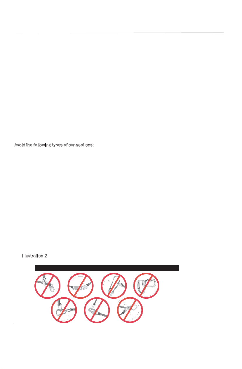
void the following types of connections:
A
• Connection of two (or more) snap hooks or carabiners to one D-ring.
• Connection of a snap hook back to its integral lanyard.
• Direct connection of a snap hook to horizontal lifeline.
• Connection in a manner that results in a load on the gate. NOTE: Large throat opening snap
hooks should not be connected to standard size D-rings or similar objects, as such use will
result in a load on the gate if the hook or D-ring twists or rotates. Large throat snap hooks
are designed for use on structural elements such as rebar or cross members that are not
shaped in such a way that they may capture the gate of the hook.
• False engagement connections, where protruding features of the snap hook or carabiner
may catch on the anchor and seem to be fully engaged to the anchor point. Always confirm
engagement.
• Connection to snap hooks or carabiners.
• Direct connection to webbing lanyard, webbing loop, rope lanyard or tie-back (unless the
manufacturer’s instructions for both the lanyard and connector specifically allow such a
connection).
• Connection of a snap hook to a D-ring, rebar, or other connection point of improper
dimensions in relation to the snap hook dimensions or configurations that could cause the
snap hook keeper to be depressed by a turning motion of the snap hook, or such that snap
hook or carabiner will not fully close and lock, or that roll-out could occur.
• I
llustration 2 depicts examples of inappropriate connections:
ook.
4 13
Illustration 2: Inappropriate Connections
Page 5
SRL – SR D Instruction Manual
Connecting Component Limitations
• A Competent Person must ensure the compatibility of all connections and that of the
system.
• Do not use the system if any connector does not lock or if any other component in the
system does not operate properly.
• Allow sufficient safe clearance in the event of a Free Fall.
• System must be rigged to limit the total Free Fall Distance according to the type of system,
and in compliance with ANSI and OSHA directives.
• Do not use if any part of the system appears to be damaged.
• Do not use a body belt for fall arrest applications.
Performance
Each Self-Retracting Lifelines have an average arresting force of 900 lbs (4kN) when statically
tested in accordance with the requirements of the ANSI Z359.14:2014 standard.
Max
Model/
Part # Description (Materials & Size)
C7000
C7001 Impac t Resist ant Pol ymer H ousing , Steel Cabl e, Steel Ca rabin er 30 ft. 54 in. B
C7002
C7003 Im pact Resi stant Polym er Housi ng, Steel Cabl e, Steel C arabin er, Sn out & Tagline 100 ft. 54 in. B
C7004
C7005 Im pact Resista nt Polym er Hous ing, Pol yester W ebbing, Steel S nap Hoo k & Swiv el 11 ft. 54 in. B
C7020
C7021
C7100
C7201
C7202
C8000 Impac t Resist ant Pol ymer H ousing , Steel Ca ble, Steel Car abiner , Steel Snap Ho ok & Tagl ine 20 ft. 54 in. B
C8001 Impact Res istant Polym er Housi ng, Steel Cabl e, Steel Carabi ner, St eel Sna p Hook & T agline 30 ft. 54 in. B
A
pplicable Standards:
Impac t Resist ant Pol ymer Housing, Steel Cable, Steel Carabiner, Snout & Tagline
Impac t Resist ant Pol ymer H ousing , Steel Ca ble, Steel Car abiner
Impac t Resist ant Pol ymer H ousing , Steel Ca ble, Steel Car abiner , Snout & Tagline
Alumi num Hou sing, Polyester Webbing, Steel Snap Hook Twin SRL
Aluminum Housing, Polyester Webbing, Steel Universal Rebar Hook Twin SRL
Impac t Resist ant Pol ymer H ousing , Polyes ter W ebbing, Steel Sn ap Hook, & Steel Carabiner
Impact Resistant Polymer Housing, Polyester Webbing, Swivel Top with
Impact Resistant Polymer Housing, Polyester Webbing, Swivel Top with
Steel Carabiner; Steel Snap Hook on Bottom
Steel Carabiner; Steel Universal Rebar Hook on Bottom
Lifeline
Length
Arrest
Distance
20 ft. 54 in. B
50 ft. 54 in. B
10 ft. 54 in. B
6 ft. 54 in. B
6 ft. 54 in. B
6 ft. 54 in. B
11 ft. 54 in. B
11 ft. 54 in. B
Z359.14
Refer to national standards, including ANSI Z359.1, and local, state and federal (OSHA 1910.66,
appendix C, 1926.500) requirements for more information on personal fall arrest systems and
associated components.
C
apacity:
Malta Dynamics Self-Retracting Lifelines are designed for use by an individual person with a
combined weight (worker, clothing, tools, etc.) of 130 lbs. minimum to no more than 310 lbs.
maximum. No more than one person may be connected at one time.
ANSI
Class
512
Page 6
SRL – SR D Instruction Manual
Anchorage Strength:
30°
Always attach to an
SRL – SR D Instruction Manual
40omax
40omax
Min. 5000lbs
Min. 5000lbs
In accordance with ANSI Z359.1, any anchorage selected for P
m
eet all anchorage strength requirements. Anchorages used for PFAS must be capable of
ersonal Fall Arrest Systems must
sustaining static loads in the direction permitted by the PFAS of at least: 3,600 lbs. with
certification of a qualified person; or 5,000 lbs. without certification. When more than one PFAS
is attached to an anchorage, the strengths stated above must be met independently at and for
each anchorage location. Avoid potential swing fall hazards and obstructions.
ree Fall:
F
Maximum free fall distance allowed for use in a Personal Fall Arrest System is 6 ft. Do not work
above the anchorage level to avoid increased Free Fall Distance. Avoid slack in the line and do not
lengthen the Self-Retracting Lifeline by connecting a lanyard or other snap hook directly to the
retractable. Do not use this device at or below the level of your feet. Using it thus will increase your
free fall distance beyond the allowable limits set by OSHA and exceed the capabilities of this
device to safely arrest a fall.
F
all Arrest Forces:
The Personal Fall Arrest System must limit fall arrest forces to 900 lbs. (4kN). Deceleration
distance shall not be allowed to exceed 42 in.
S
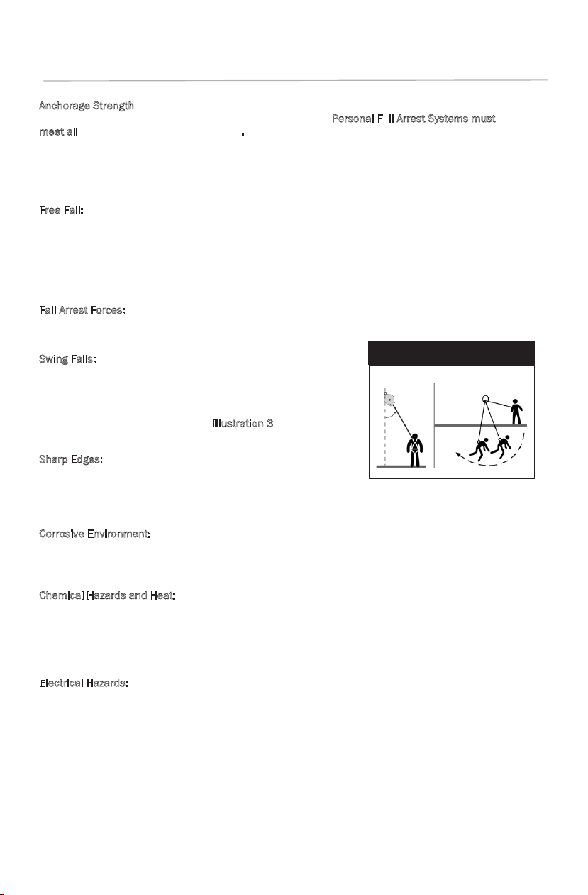
wing Falls:
Self-Retracting Lifelines should be used in a vertical position only.
Minimize swing fall by working as directly below the anchorage
point as possible. Worker movement should remain within 30
degrees maximum deflection of the lifeline from the vertical line
directly below the anchorage point. (
I
llustration 3). Do not permit a
Illustration 3: Minimize Swing Fall
overhead anchor. Swing
falls significantly increase
fall arrest
distance.
swing fall if injury could occur.
S
harp Edges:
working where sharp edges may contact lifeline. Provide
Avoid
sufficient protective
possible. Malta Dynamics
padding where avoiding sharp edges is not
energy absorbing device may be required to reduce impact force on the
entire system.
C
orrosive Environment:
Extensive exposure to environments where corrosion may occur will damage metal parts in the
Self-Retracting Lifeline. Use caution when working around corrosive compounds such as
ammonia, sewage, fertilizers, sea water or other corrosives.
C
hemical Hazards and Heat:
Use extreme caution
temperatures, as chemical damage that can impair the
in environments containing acid or caustic chemicals, particularly at elevated
functionality of the Self-Retracting Lifeline
(SRL) is difficult to detect. Periodic replacement of the SRL is recommended to ensure safety. Do not
use SRL in high temperature environments. Protect SRL if used near welding, metal cutting, or similar
activities. Hot sparks and slag can damage
E
lectrical Hazards:
Use extreme
caution to avoid contact with high voltage power lines. Both web and wire cable model
SRL and impair functionality.
Self-Retracting Lifelines may conduct electricity. Moisture absorbed by the lifeline can provide a
path for electrical current
to flow, resulting in potential electrical shock.
General Adverse Environment Conditions:
User must be aware of working conditions and environment during all aspects of use. Adverse
working conditions and environment require additional attention and extreme caution. Adverse
working conditions and environments include but are not limited to areas involving mortar/cement/
concrete, dust/demolition, caustic/corrosive materials, falling objects, gypsum, slurry, petroleum
based liquids, extreme wet conditions, mud, or metal/plastic shavings. User is to use extreme
caution of materials that may adhere to or strike the SRL line constituent. Material that adheres to
line constituent may damage parts within the Self-Retracting Lifeline and may lead to
6
serious injury or death. Falling objects that strike the SRL line constituent may cause a fall
to occur in addition to weakening or breaking the SRL and anchorage which will may result
in serious injury or death.
Page 7

SRL – SR D Instruction Manual
Locking Speed:
A. Connecting Su bsystems (Energy
Illustration 4:
Considerations
6 ft. Free Fall
ANCHORAGE
Total Min.
Anchorage
6 ft. Energy
12 ft. Free Fall
6 ft. Energy
Total Min.
Anchorage
Illustration 5: Calculating Total Fall Distance
ANCHORAGE
Use extreme caution when working on low-pitched roofs where a worker may slide, rather than fall. A
clear path is require to ensure positive locking of the Self-Retracting Lifeline.
F
all Clearance:
Consider the following when calculating fall clearance. Clearance required is dependent on the following
factors:
• Elevation of Anchorage
• Connecting Subsystem Length
• Deceleration Distance
Fall Clearance
• Free Fall Distance
• Worker Height
• D-ring / connector length
• Movement of Harness Attachment Element
• Length of Full Body Harness (FBH) Stretch
• Working Level
See I
llustration 4.
If there is a risk of a fall or if the only anchorage
point is below the attachment points on the
harness, it is essential to use a lanyard
provided with an energy absorber. Before using
a shock absorbing lanyard, ensure that there is
sufficient fall clearance below the user to
Absorbing Lanya rd shown) Length
+ Movement of H arness Attachment
+ Length of FBH Stretch
B. Working Level (thickness)
C. Worker Height + Connector Length
D. Free Fall – 6 ft. Max. (per ANSI Z359.1)
E. Decelerati on Distance
F. Total Fall Distance: Sum of A through E
G. Lower Level or Obstruction
prevent any collision with the structure or the
ground.
C
alculating Total Fall Distances:
Total Fall Clearance below worker is calculated from Anchorage Connection. Free Fall Distance +
Working Level + Energy Absorber + Deceleration Distance + Worker Height + Connector Length +
Safety Factor. Ensure that the total fall distance is clear of obstructions and equipment. Avoid
potential contact with a lower level. See
I
llustration 5.
19 ft. from
Absorbing
Lanyard
Length
4 ft.
Decel
eration
Distance
6 ft. Worker
Height
3 ft. Safety
Factor
20 ft. from
ENERG Y
ABSORBING
LANYARD MUST BE
CERTIFIED FOR 12
FT. FREE FALL
Absorbing
Lanyard
Length
5 ft.
Decel
eration
Distance
6 ft. Worker
Height
3 ft. Safety
Factor
7
Page 8

SRL – SR D Instruction Manual
Horizontal Systems and Tripods:
Illustration 6: Inspection
SRL – SR D Instruction Manual
MIN. 5000 lbs
22kN
40omax
310lbs
Max
follow
for
instructions
proper
SRL
attachment
GREEN
RED
directlyto
horizontal
54oC
-40
o
C
130oF
-40
o
F
SUITABLE FOR
HORIZONTAL
LIFELINE
800-494-1840
405 Watertown Road
Waterford, OH 45786
40omax
Ensure the support structure and/or horizontal system components are compatible if using SelfRetracting Lifeline in conjunction with a horizontal system, tripod or davit arm. Horizontal systems
must be designed and installed under the supervision of a qualified engineer.
Training
Employers are responsible for providing training to any employee who may be exposed to fall hazards
in order to enable the employee to recognize and reduce fall hazards. Training must be conducted by
a Competent or Qualified Person. Trainer and trainees must not be exposed to fall hazards during
the training course.
Inspection
Record all observations and results of each inspection in your Hog Tracker account or inspection
log. I
f inspection reveals any defect, inadequate maintenance, or unsafe condition, remove Full
B
ody Harness from service immediately.
A
fter a Fall:
Remove Self-Retracting Lifeline (SRL) from service immediately after a fall has occurred. Inspect the
impact indicator on the snap hook of the SRL; look for an exposed red color band. Do not reset the
impact indicator. SRL with a webbed lifeline requires additional inspection of the shock pack, looking
for deformation, elongation or other signs of the shock pack being torn or deployed.
lf-Retracting Lifeline (SRL) must be inspected by a Competent Person a minimum of twice per year
Se
(every six months). If the SRL is exposed to extreme or severe conditions, more frequent formal
inspections may be required. Record the results of each formal inspection in your Hog Tracker
account or inspection log.
U
ser Inspection
Self-Retracting Lifeline (SRL) should be inspected by the user before each use, using the inspection
procedures below (I
and inspected to ensure:
• Markings are legible
• Components are free from corrosion, bending, cracks, dents or deformity
• SRL is clean and free of dirt, oil, mold, mildew and contaminants
llustration 6). In addition, unit should be fully examined
nspection Procedure
I
S
tep 1: Inspect for loose screws and bent or damaged parts.
S
tep 2: Inspect housing for distortion, cracks or other damage. Ensure
swivel eye is not damaged or distorted. Swivel eye must turn
freely.
S
tep 3: Ensure lifeline extends and retracts fully without hesitation or
creation of slack in the line.
tep 4: Ensure device engages (locks up) when lifeline is jerked
S
(tugged) sharply.
tep 5: Inspect wire cable lifelines for cuts, kinks, broken wires, bird-
S
caging corrosion, welding splatter, chemical damage or severe
abrasion. Check all thimbles and other areas for excessive wear,
including cracks or separation of metal components.
S
tep 6: Inspect webbed lifelines for frayed strands, broken webbing,
burns, cuts and abrasions. Look for heat damage, paint build-up,
corrosion and chemical damage indicated by discoloration.
8 9
Page 9
SRL – SR D Instruction Manual
Step 7: Inspect all snap hooks and connectors for damage; ensure secure, locking engagement
MIN. 5000 lbs
22kN
40omax
310lbs
Max
follow
for
instructions
proper
SRL
attachment
GREEN
RED
directlyto
horizontal
54oC
-40
o
C
130oF
-40
o
F
SUITABLE FOR
HORIZONTAL
LIFELINE
800-494-1840
405 Watertown Road
Waterford, OH 45786
40omax
able Inspection Considerations:
C
User must be aware of the potential for damage or deterioration that may occur while in use.
C
rushing: Cable may get crushed or bent while in general use, resulting in unsafe condition for use.
C
utting: Movement over sharp edges or other objects while cable in under tension can damage or
break strands, resulting in an unsafe condition for use.
brasion: Normal wear can result in abrasion. Pay particular attention to outer strands, which are most
A
susceptible to abrasion. Extreme abrasion results in an unsafe condition for use.
inking: Deformation in the cable causes the lifeline to appear bent or kinked, and results in an unsafe
K
condition for use.
orrosion Damage: Use extreme caution to avoid potential damage when using a Self-Retracting
C
Lifeline in an environment where corrosive compounds, welding or high heat may exist. Corrosion
damage can cause cable to crack. Working in a corrosive environment requires increased inspection
frequency to ensure corrosive damage does not impact the performance of the SRL.
A
rc or Heat Damage: Welding or high heat may fuse cable wires and change the strength
characteristics of the wire and cable as a whole. Periodically examine the SRL if it must be used in
these types of environments.
Cleaning and Maintenance
C
leaning
Wipe off all surface dirt. Store in clean, dry area, away from heat and areas where chemical vapors may
exist. Avoid storing in direct light to prevent UV degradation.
M
aintenance
Do not attempt to disassemble or repair. O
D
ynamics shall make repairs, authorized maintenance or alterations to the equipment.
uct Labels
Prod
nly Malta Dynamics or entities authorized in writing by Malta
The following labelling is affixed to product and must not be removed:
CLASS B SRD
SRL -Weight: -8.5 -lbs.
Max -Arresting-Distance:-54-in..
Material:
steel,
aluminum housing
2
with Carabiner, Steel Snap Hook,
Snout and Tag Line
Average -Arresting -Force: 900 -lbs.
Capacity: -1 -Person
Working -Load: -130-310 -lbs.
®
MIN. 5000 lbs
22kN
follow
54oC
130oF
instructions
GREEN
RED
800-494-1840
405 Watertown Road
Waterford, OH 45786
-40
310lbs
Max
SUITABLE FOR
proper
for
HORIZONTAL
o
o
-40
F
C
LIFELINE
SRL
attachment
directlyto
horizontal
C7000
Page 10

40omax
SRL – SR D Instruction Manual
A. Connecting Su bsystems (Energy
Illustration 4:
Considerations
6 ft. Free Fall
ANCHORAGE
Total Min.
Anchorage
6 ft. Energy
12 ft. Free Fall
6 ft. Energy
Total Min.
Anchorage
Illustration 5: Calculating Total Fall Distance
ANCHORAGE
SRL – SR D Instruction Manual
40omax
310lbs
50oC
-30
o
C
122oF
-22
o
F
40omax
Max
MIN. 5000 lbs
22kN
GREEN
with Carabiner, Steel Snap Hook,
54oC
RED
follow
130oF
SUITABLE FOR
instructions
HORIZONTAL
proper
for
o
o
F
-40
-40
C
attachment
LIFELINE
SRL
Materials:- Impact -Resistant-Polymer-Housing,
Steel-Cable,-Steel-Hardware
Average -Arresting-Force: 900-lbs.
Snout and Tag Line
SRL -Weight:-8.7-lbs.
Capacity:-1-person
Working -Load:-130-310-lbs.
Max -Arresting-Distance:-54-in.
C7001
310lbs
Max
CLASS B SRD
Materials:- Impact -Resistant-Polymer-Housing,
---------- ----- Polyester-Webbing,-Steel-Hardware
800-494-1840
405 Watertown Road, Waterford, OH 45786
MIN. 5000 lbs
22kN
GREEN
RED
800-494-1840
405 Watertown Road, Waterford, OH 45786
1
Materials:- Impact -Resistant-Polymer -Housing,
Average-Arresting-Force:-900-lbs.
Max-Arresting-Distance:-54-in.
----------- ---- ---- --- -- --- Steel - Cable,-Steel-Hardware
130oF
o
o
-40
F
C
Working-Load: -130-310-lbs.
follow
SUITABLE FOR
instructions
HORIZONTAL
proper
for
LIFELINE
SRL
attachment
Snout and Tag Line
Capacity:-1-Person
54oC
-40
with Carabiner, Steel Snap Hook,
C7002
™
C7003
Average -Arresting-Force: 900-lbs.
MIN. 5000 lbs
22kN
GREEN
310lbs
Max
Class -B -SRD
with Carabiner, Steel Snap Hook,
Materials:- Impact -Resistant-Polymer-Housing,
Steel-Cable,-Steel-Hardware
Class -B -SRD
54oC
RED
130oF
o
o
F
-40
-40
C
Snout and Tag Line
SRL -Weight:-8.7-lbs.
Capacity:-1-person
Working -Load:-130-310-lbs.
Max -Arresting-Distance:-54-in.
follow
instructions
SUITABLE FOR
proper
for
HORIZONTAL
SRL
LIFELINE
attachment
3
10
Page 11

SRL – SR D Instruction Manual
40omax
CLASS B SRD
40omax
Min. 5000lbs
Min. 5000lbs
SRL -Weight: -8 -lbs.
Max -Arresting-Distance: 54-in.
CLASS B SRD
SRL -Weight: -5.2 -lbs.
Max -Arresting-Distance: 54-in.
1
with Carabiner, Steel Snap Hook,
Materials:- Impact - Resistant-Polymer-Housing,
---------- ----- Polyester -Webbing,-Steel-Hardware
Average -Arresting-Force: 900-lbs.
®
1
1
11
’ Webbing with Swivel & Snap Hook
Materials:- Impact -Resistant-Polymer-Housing,
---------- ----- Polyester-Webbing,-Steel-Hardware
Average -Arresting-Force: 900-lbs.
Working-Load: -90-130-lbs.
®
CLASSBSRD
C7020
PART#
Weight: -5.2 - lbs.
SERIAL#
BATCH#
MFG
DATE:
54oC 130oF
310lbs
-40oC -40oF
Max
™
Snout and Tag Line
Capacity:-1-Person
Working-Load: -130-310-lbs.
™
Capacity:-1-Person
6'
follow
instructions
for
_
proper
SRL
attachment
22kN
SUITABLE FOR
HORIZONTAL
LIFELINE
310lbs
Max
Twin
Self-Retracting
GREEN
RED
MIN. 5000 lbs
22kN
GREEN
with
MIN. 5000 lbs
22kN
GREEN
RED
310lbs
Max
54oC
130oF
RED
o
C
-40
800-494-1840
405 Watertown Road
Waterford, OH 45786
Steel- Snap
Average -Arresting -Force: 900lbs.
Working- Load: 130-310lbs.
Max Distance:
800-494-1840
405 Watertown Road
Waterford, OH 45786
800-494-1840
405 Watertown Road
Waterford, OH 45788
follow
instructions
proper
for
o
-40
F
SRL
attachment
™
Lifeline
Capacity: 1 person
Arrest
54oC
o
C
-40
SUITABLE FOR
HORIZONTAL
LIFELINE
Hook
4
C7004
follow
130oF
instructions
SUITABLE FOR
proper
HORIZONTAL
for
o
-40
F
LIFELINE
SRL
attachment
SUITABLE FOR
HORIZONTAL
LIFELINE
C7005
54"
C7020
CLASSBSRD
C7021
PART#
310lbs
Max
SERIAL#
BATCH#
MFG
Weight: -5.2 - lbs.
DATE:
54oC 130oF
-40oC -40oF
instructions
for
attachment
6'
follow
_
proper
SRL
22kN
SUITABLE FOR
HORIZONTAL
LIFELINE
Twin
Self-Retracting
GREEN
RED
™
with- Universal- Rebar- Hook
Lifeline
Average -Arresting -Force: 900lbs.
Capacity: 1 person
Working- Load: 130-310lbs.
Max Distance:
Arrest
800-494-1840
405 Watertown Road
Waterford, OH 45786
54"
C7021
Page 12

SRL – SR D Instruction Manual
SRL – SR D Instruction Manual
PART# C7201
™
SRL -Weight:-5-lbs.
11’ Polyester Webbing, Swivel Top with
Carabiner ; Snap Hook on Bottom
Capacity:-1-person
Working -Load:-130-310-lbs.
Max -Arresting-Distance:-54-in.
Average -Arresting-Force:
Materials:- Impact -Resistant -Polymer-Housing,-
------------ Polyester-Webbing,-Steel-Hardware
Class -B -SRD
Materials:- Impact -Resistant-Polymer-
-Housing, -Polyester-Web,-
--Steel-Hardware
Capacity:-1-person
SRL -Weight:-5-lbs.
Class -B -SRD
CLASSBSRD
C7021
PART#
900-lbs.
with Universal Rebar Hook
Average -Arresting-Force:
900-lbs.
Working -Load:-130-310-lbs.
Max -Arresting-Distance:-54-in.
Weight: -5.2 - lbs.
SERIAL#
BATCH#
MFG
DATE:
310lbs
™
6'
Max
Twin
MIN. 5000 lbs
22kN
GREEN
RED
800-494-1840
Watertown Road, Waterford, OH 45786
MIN. 5000 lbs
22kN
310lbs
Max
Self-Retracting
with- Universal- Rebar- Hook
™
40omax
54oC
130oF
instructions
for
o
o
-40
F
-40
C
attachment
800-494-1840
405 Watertown Road, Waterford, OH 45786
™
40omax
54oC
130oF
GREEN
RED
o
o
-40
C
-40
SUITABLE FOR
HORIZONTAL
LIFELINE
™
Lifeline
Average -Arresting -Force: 900lbs.
Capacity: 1 person
Working- Load: 130-310lbs.
Max Arrest Distance:
follow
SUITABLE FOR
proper
HORIZONTAL
LIFELINE
SRL
follow
instructions
proper
for
F
SRL
attachment
C7201
C7103
54"
C7021
310lbs
54oC 130oF
follow
instructions
for
_
proper
-40oC -40oF
SRL
Max
attachment
SUIT
HORIZONT
LIFELINE
GREEN
RED
Min. 5000lbs
22kN
ABLE FOR
AL
800-494-1840
405 Watertown Road
Waterford, OH 45786
Page 13

SRL – SR D Instruction Manual
Materials:- Impact-Resistant-Polymer-Housing,
Steel-Cable,-Steel-Hardware
40omax
Materials:- Impact-Resistant-Polymer-Housing,
Steel-Cable,-Steel-Hardware
40omax
40omax
PART# C7202
SRL -Weight:-5-lbs.
CLASS B SRD
Max-Arresting-Distance:-54-in.
Working-Load: -130-310-lbs.
Capacity:-1-Person
Average-Arresting-Force:-900-lbs.
Materials: -Impact -Resistant-Polymer
Housing,-Steel-Cable,-Steel-Hardware
11’ Polyester Webbing, Swivel Top with
Carabiner; Universal Rebar Hook on Bottom
Max -Arresting-Distance:-54-in.
Average -Arresting-Force:
Materials:- Impact -Resistant -Polymer-Housing,-
------------ Polyester-Webbing,-Steel-Hardware
Class -B -SRD
Materials: -Impact -Resistant-Polymer
Housing,-Steel-Cable,-Steel-Hardware
™
Capacity:-1-person
Working -Load:-130-310-lbs.
900-lbs.
310lbs
Max
MIN. 5000 lbs
22kN
310lbs
Max
MIN. 5000 lbs
22kN
GREEN
RED
405 Watertown Road, Waterford, OH 45786
GREEN
RED
800-494-1840
405 Watertown Road, Waterford, OH 45786
54oC
o
-40
C
800-494-1840
54oC
130oF
instructions
for
o
o
F
-40
-40
C
attachment
C7202
™
follow
130oF
instructions
SUITABLE FOR
proper
HORIZONTAL
for
o
-40
F
LIFELINE
SRL
attachment
C8000
SUITABLE FOR
HORIZONTAL
LIFELINE
follow
proper
SRL
CLASS B SRD
Max-Arresting-Distance:-54-in.
Working-Load: -130-310-lbs.
Capacity:-1-Person
Average-Arresting-Force:-900-lbs.
3/16” diameter
Galvanized Steel Cable
with Carabiner, Swivel Top
Steel Snap Hook & Tag Line
MIN. 5000 lbs
22kN
310lbs
Max
GREEN
RED
800-494-1840
405 Watertown Road, Waterford, OH 45786
C8001
SUITABLE FOR
HORIZONTAL
LIFELINE
follow
54oC
130oF
instructions
proper
for
o
o
F
-40
C
-40
SRL
attachment
Page 14

SRL – SR D Instruction Manual
Illustration
1: Examples
of
Swing
Fall Hazards
SRL – SR D Instruction Manual
Inspection Log
Date of Manufacture: Model Name/#:
Serial #: Date of First Use:
INSPECTION DATE ITEMS NOTED CORRECTIVE ACTION APPROVED BY
14
8
00-494-1840
405 Watertown Road, Waterford, OH 45786
Page 15

SRL – SR D Instruction Manual
Warranty
THE FOLLOWING IS MADE IN LIEU OF ALL WARRANTIES OR CONDITIONS, EXPRESS OR IMPLIED,
INCLUDING THE IMPLIED WARRANTIES OR CONDITIONS OF MERCHANTABILITY OR FITNESS FOR A
PARTICULAR PURPOSE. Equipment offered by Malta Dynamics is warranted against factory defects
in workmanship and materials for a period of one year from date of installation or first use by the
original owner. LIMITED REMEDY: Upon notice in writing, Malta Dynamics will repair or replace all
defective items at Malta Dynamics’s sole discretion. Malta Dynamics reserves the right to require
that the defective item be returned to its plant for inspection before determining the appropriate
course of action. Warranty does not cover equipment damage resulting from wear, abuse, damage
in transit, failure to maintain the product or other damage beyond the control of Malta Dynamics.
Malta Dynamics shall be the sole judge of product condition and warranty options. This warranty
applies only to original purchaser and is the only warranty applicable to this product. Please contact
Malta Dynamics customer service department at 800-494-1840 for assistance. LIMITATION OF
LIABILITY: IN NO EVENT WILL MALTA DYNAMICS BE LIABLE FOR ANY INDIRECT, INCIDENTAL,
SPECIAL OR CONSEQUENTIAL DAMAGES INCLUDING, BUT NOT LIMITED TO LOSS OF PROFITS, IN
ANY WAY RELATED TO THE PRODUCTS REGARDLESS OF THE LEGAL THEORY ASSERTED.
Page 16

SRL – SRD Instruction Manual
te of First Use:
INSPECTION DATE ITEMS NOTED CORRECTIVE ACTION APPROVED BY
1
SRL – SR D Instruction Manual
MaltaDynamics
8
405 Watertown Road, Waterford, OH 45786
8
00-494-1840
405 Watertown Road, Waterford, OH 45786
 Loading...