

Page 1
Visit MaltaDynamics.com for the latest user instruction
manual revision available for this product offering.
Page 2

Full Body Harness
Z359.1-2007
Z359.3-2007
Z359.1-2007 &
INSTRUCTION MANUAL
These instructions apply to the following model(s):
D
N
H
A
E
A
Y
L
T
T
E
F
A
S
L
A
N
O
I
T
A
P
U
C
C
O
OSHAOSHA
H
A
D
M
I
N
I
S
T
R
A
T
I
O
N
COMPLIANT
M
A
L
T
A
D
M
O
C
.
S
C
Y
I
N
M
A
S
T
A
L
N
A
D
N
A
O
I
T
A
N
N
A
C
I
R
E
M
A
ANSIANSI
ANSI
R
D
S
I
N
S
T
I
T
U
T
E
Z359.1-2007
M
A
L
T
A
D
B2000 Full Body Harness
B2001 Full Body Harness
M
O
C
.
S
C
Y
I
N
M
A
E
M
A
Z359.1-2007 &
Z359.3-2007
B2102 Full Body Harness
(Malta Dynamics Branded)
B2103 Full Body Harness
(Malta Dynamics Branded)
S
L
A
N
O
I
T
A
N
N
A
C
I
R
ANSIANSI
ANSI
M
A
L
T
A
D
Y
N
A
T
A
N
D
A
R
D
S
I
N
S
T
I
T
U
T
E
M
O
C
.
S
C
I
M
B2002 Full Body Harness B2106 Full Body Harness
B2003 Full Body Harness
B2100 Full Body Harness
B2101 Full Body Harness
B2102 Full Body Harness
(EZLifLine Branded)
B2103 Full Body Harness
(EZLifLine Branded)
B2105 Full Body Harness
Full Body Harness User Instruction Manual
MaltaDynamics.com | 800-494-1840
Manual Revision Code:
MD-FBHUIM161216
Please visit www.MaltaDynamics.com for the latest
user instruction manual revision available for this product offering.
2
Manual Revision Code:
M
D-FBHUIM161216
Page 3

TABLE OF CONTENTS
Under Penalty of Law ------------------------------------------------ 4
Materials & Construction -------------------------------------------- 4
Purpose ----------------------------------------------------------------- 5
Instructions for Use -------------------------------------------------- 6
Limitations for Use --------------------------------------------------- 7
Connector Compatibility Limitations ------------------------------ 8
Connecting Component Limitations ------------------------------- 10
Performance ----------------------------------------------------------- 10
Anchorage Requirements -------------------------------------------- 11
Fall Clearance Requirements ---------------------------------------- 12
Donning the Full Body Harness -------------------------------------- 14
Parts of the Full Body Harness -------------------------------------- 16
Training ----------------------------------------------------------------- 16
Inspection -------------------------------------------------------------- 17
Cleaning and Maintenance ------------------------------------------ 19
Product Specifc Applications --------------------------------------- 19
Applicable Uses for the Full Body Harness ---------------------- 20
Product Labels -------------------------------------------------------- 21
Inspection Log -------------------------------------------------------- 26
Warranty --------------------------------------------------------------- 27
Visit MaltaDynamics.com for the latest user instruction
manual revision available for this product offering.
3
Full Body Harness User Instruction Manual
MaltaDynamics.com | 800-494-1840
Page 4
UNDER PENALTY OF LAW
WARNING
WARNING
This manual must be read and understood in its entirety, and used as part of a
fall protection training program, as required by OSHA or any state/local regulatory
agencies.
This manual is intended to meet industry standards required by ANSI Z359.0-2007
Fall Protection Code. The user must read and fully understand the limitations and
proper use of the equipment, and be properly trained by the employer prior to use.
NOTE: This User Instruction Manual is not to be removed except by the equipment
user. Current User Instruction Manuals must always be available to the user. Read
and understand these instructions before using equipment. Do not discard these
instructions.
Misuse or failure to follow warnings, instructions, and limitations
on the use of this equipment may result in serious personal
injury or death. For further instructions about proper use, refer
to supervisor or contact Malta Dynamics at 1-800-494-1840.
MATERIALS AND CONSTRUCTION
Webbing Materials
• High tenacity polyester; breaking strength >5000 lbs. tensile strength
Connector Materials
• Galvanized Steel
Full Body Harness User Instruction Manual
MaltaDynamics.com | 800-494-1840
4
Manual Revision Code:
M
D-FBHUIM161216
Page 5
PURPOSE
Malta Dynamics Full Body Harnesses are Class 3 full body harnesses designed
for an array of full-body applications. Such full body harnesses are the only form
of body wear acceptable for fall arrest. Full body harnesses may also be used for
positioning, travel restraint, and rescue.
Malta Dynamics Harnesses are designed and tested to comply with applicable
OSHA and ANSI standards for fall protection equipment. When used as a
component in a personal fall arrest system or personal restraint system, Malta
Dynamics Full Body Harnesses comply with OSHA directives for fall protection
wear. Full body harnesses serve to better distribute the forces of a fall to suitable
areas of a body and keep the body upright should a fall occur.
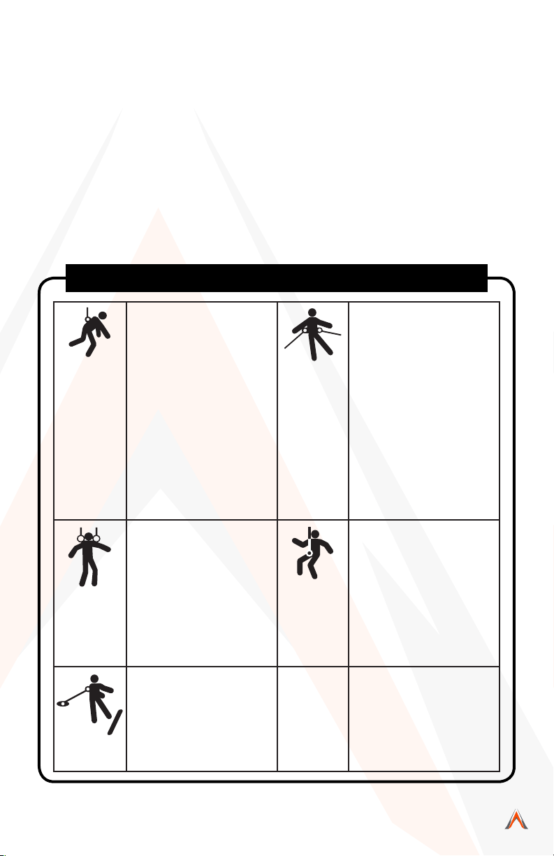
Illustration 1: Applications
Personal Fall Arrest:
The full body harness is used
as a component of a personal
fall arrest system. Personal fall
arrest systems typically include
a full body harness and a
connecting subsystem (energy
absorbing lanyard). Maximum
arresting force must not exceed
900 lbs (4 kN), for fall arrest applications connect the fall arrest
subsystem (example: lanyard,
SRL, energy absorber, etc.)
to the D-ring or attachment
element on your back, between
your shoulder blades.
Rescue:
The full body harness is used
as a component of a rescue
system. Rescue systems are
congured depending on the
type of rescue. For limited access (conned space) applications, harnesses equipped with
D-rings on the shoulders may
be used for entry and egress
into conned spaces where
worker prole is an issue.
Restraint:
The full body harness is used
as a component of a restraint
system to prevent the user from
reaching a fall hazard. Restraint
systems typically include a full
body harness and a lanyard or
restraint line.
Work Positioning:
The full body harness is used
as a component of a work positioning system to support the
user at a work position. Work
positioning systems typically include a full body harness, positioning lanyard, and a back-up
personal fall arrest system. For
work positioning applications,
connect the work positioning
subsystem (example: lanyard,
Y-lanyard, etc.) to the lower (hip
level) side or belt mounted work
positioning attachment anchorage elements (D-rings). Never
use these connection points for
fall arrest.
Controlled Descent:
For controlled descent applications, full body harnesses
equipped with a single sternal
level D-ring, one or two frontal
mounted D-rings, or a pair of
connectors originating below
the waist (such as a seat sling)
may be used for connection
to a descender or evacuation
system.
Visit MaltaDynamics.com for the latest user instruction
manual revision available for this product offering.
Full Body Harness User Instruction Manual
5
MaltaDynamics.com | 800-494-1840
Page 6
INSTRUCTIONS FOR USE
WARNING
WARNING
Do not alter or intentionally misuse this equipment.
• Full Body Harnesses which meet Z359.1-2007 and Z359.3 are
intended to be used with other components of a Personal Fall Arrest
system that limit maximum arrest forces to 1800 pounds (8 kN) or less.
• Employees shall be trained in accordance with the requirements
of OSHA 29 CFR 1910.66 in the safe use of the system and its
components before using a PFAS.
• Inspect all PFAS equipment for wear, damage, and other deterioration
prior to each use. Remove defective equipment from service
immediately.
• Thoroughly evaluate and plan all elements of Fall Protection System(s)
before using this equipment. Make sure that your Personal Fall
Arrest System is appropriate for your needs and facility. Calculate
fall clearance and swing fall clearance. The clearance required is
dependent on the type of connecting subsystem, the anchorage
location, and other factors. When calculating distance, be sure to
consider:
• Deceleration Distance & Free-Fall Distance
• Movement of Harness Attachment (D-Ring)
• Worker Height (how tall is the worker?)
• Elevation of Anchorage Connector
• Connecting Subsystems Length & D-Ring Connector Length
• Length of Full Body Harness Stretch
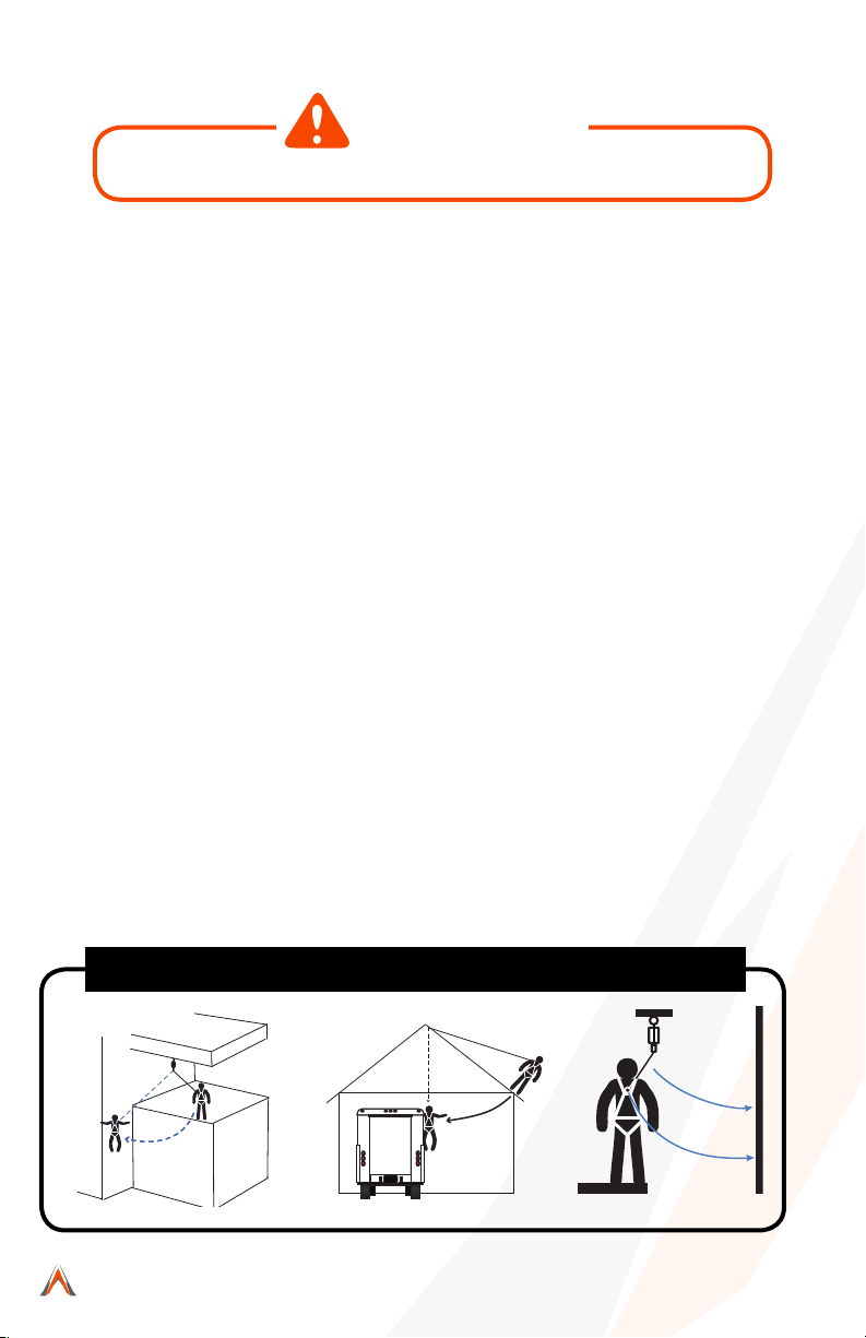
• Swings fall occur when the anchorage point is not directly above the
point where a fall occurs. The force of striking an object in a swing fall
may cause injury or death. Minimize potential swing falls by working
as closely to the anchorage point as possible. Swing falls signcantly
increase the amount of clearance required. See Illustration 2, below:
Illustration 2: Examples of Swing Fall Hazards
Full Body Harness User Instruction Manual
MaltaDynamics.com | 800-494-1840
6
Manual Revision Code:
M
D-FBHUIM161216
Page 7
• Users must have a written rescue plan and the means to implement it.
WARNING
WARNING
WARNING
WARNING
This plan must provide prompt employee rescue or ensure employees
have the ability to rescue themselves in the event of a fall.
• Store this equipment in a cool, dry, and clean environment that is out
of direct light when not in use to prevent UV degradation.
• This equipment must be removed from service IMMEDIATELY if a fall
is incurred or if any part of the load indicator warning is showing.
LIMITATIONS FOR USE
Do not use this equipment if you are unable to tolerate the
impact of a fall arrest. Age and tness can seriously affect your
ability to withstand a fall. Consult with a physician if in doubt.
Minors, pregnant women, and anyone with a history of back
and/or neck problems must not use this equipment.
Use caution when employing this equipment around machines,
electrical hazards, chemical hazards and sharp edges or
abrasive surfaces, as contact may cause equipment failure,
personal injury, or death.
• Use only with compatible components. Substitutions or replacements
made with non-approved components or subsystems may jeopardize
compatibility of equipment and may affect the safety and reliability of
the complete system.
• Part numbers B2000, B2001, B2002, B2003, B2100, B2101, B2102,
B2103, B2105, and B2106 are designed for a single user with combined
weight—including clothing, tools, etc.—within a weight capacity range
of 130 to 310 pounds.
• Use only with structures capable of supporting static loads required for
Personal Fall Arrest Systems (PFAS). Anchorages used for PFAS must
be capable of sustaining static loads in the direction permitted by the
PFAS of at least: 3,600 pounds with certication of a qualied person,
or 5,000 pounds without it. When more than one PFAS is attached to
an anchorage, the strengths stated above must be met independently
at and for each anchorage location.
Visit MaltaDynamics.com for the latest user instruction
manual revision available for this product offering.
7
Full Body Harness User Instruction Manual
MaltaDynamics.com | 800-494-1840
Page 8

• Do not expose this equipment to chemicals or harsh solutions that may
have a harmful effect.
• User must not use or install equipment before receiving proper training
from a competent person, as dened by OSHA 29 CFR 1926.32(f).
• Only Malta Dynamics shall make repairs or alterations to the equipment.
• All synthetic material must be protected from slag, hot sparks, open
ames, or other heat sources. The use of heat-resistant materials is
recommended in these applications.
CONNECTOR COMPATIBILITY LIMITATIONS
Malta Dynamics’ equipment must be coupled only to compatible connectors that
are suitable to your application. Ensure all connections are compatible in size,
shape, and strength. Ensure all connectors are fully closed and locked. OSHA
29 CFR 1926.502 prohibits the use of snap hooks to engage objects unless the
following requirements are met:
• Snap hook must be a locking model.
• Snap hook must be explicitly designed for such a connection.
Use of a non-locking snap hook can result in rollout (a process by which a snap
hook or carabiner unintentionally disengages from another connector or the
object to which it is coupled (ANSI Z359.0- 2007). Malta Dynamics connectors
(snap hooks and carabiners) are designed to be used only as specied in each
product’s user’s instructions.
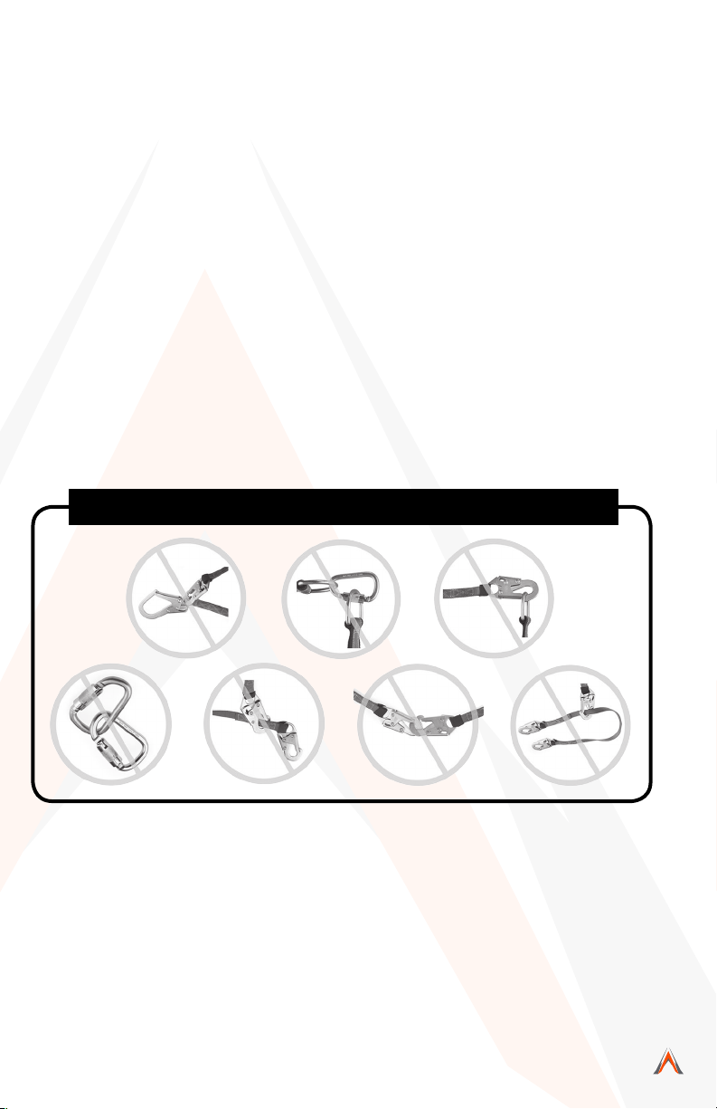
Avoid the following types of connections:
• Two or more snap hooks or carabiners attached to one D-Ring.
• A snap hook connected to its integral lanyard.
• A snap hook connected to a horizontal lifeline.
• Connection in a manner that results in a load on the gate. NOTE: Large
throat opening snap hooks should not be connected to standard size
D-Rings or similar objects, as such use will result in a load on the gate
if the hook or D-Ring twists or rotates. Large throat snap hooks are
designed for use on structural elements such as rebar or cross members
that are not shaped in such a way that they may capture the gate of the
hook.
• False engagement connections, where protruding features of the snap
hook or carabiner may catch on the anchor and seem fully engaged to
the anchor point. Always conrm engagement.
• Connection to snap hooks or carabiners.
• Direct connection to webbing lanyard, webbing loop, rope lanyard or
tie-back (unless the manufacturer’s instructions for both the lanyard
and connector specically allow such a connection).
Full Body Harness User Instruction Manual
MaltaDynamics.com | 800-494-1840
8
Manual Revision Code:
M
D-FBHUIM161216
Page 9
• Malta Dynamics’ Full Body Harnesses shall be used as part of a
personal fall arrest system that limits the maximum free-fall distance to
six feet (1.8 m). If used with appropriate connecting systems, the Full
Body Harnesses may be used with free falls exceeding six feet (1.8m)
• Full Body Harnesses shall only be used as part of a work positioning
system that limits the maximum free-fall distance to two feet (0.6 m).
• Personal Energy Absorbers and Energy Absorbing Lanyards marked
with, “ANSI Z359.13,” and “Six-Foot Free Fall” are designed for up to
six feet. Free-fall applications have a maximum capacity of 310 pounds.
(141 kg) including clothing, tools, etc.
• Not all fall protection components are rated for the same user weight
capacity. ONLY use components rated for the same weight capacity.
• This equipment is designed to be used in temperatures ranging from
-40ºF to +130ºF (-40°C to +54°C).
• Connection of a snap hook to a D-Ring, rebar, or other connection point
of improper dimensions in relation to the snap hook dimensions or
congurations that could cause the snap hook keeper to be depressed
by a turning motion of the snap hook, or such thatsnap hook or carabiner
will not fully close and lock, or that roll-out could occur.
• Illustration 3 depicts examples of inappropriate connections:
Illustration 3: Inappropriate Connections
Visit MaltaDynamics.com for the latest user instruction
manual revision available for this product offering.
Full Body Harness User Instruction Manual
9
MaltaDynamics.com | 800-494-1840
Page 10

CONNECTING COMPONENT LIMITATIONS
• A Competent Person must ensure the compatibility of all connections
and of the system.
• Do not use the system if any connector does not lock or if any other
component in the system does not operate properly.
• Allow sufcient safe clearance in the event of a free fall.
• System must be rigged to limit the total free-fall distance according to
the type of system, and in compliance with ANSI and OSHA directives.
• Do not use if any part of the system appears to be damaged.
• Do not use a body belt for fall arrest applications.
PERFORMANCE
Each Malta Dynamics’ Full Body Harness has a minumum tensile breaking
strength of 5,000 pounds (22.2 kN) when statically tested in accordance with
the requirements of the ANSI Z359.1-2007 standard. Malta Dynamics’ Full Body
Harnesses stretch is less than eight inches.
Model/
Part #
B2000
B2001
B2002
B2003
B2100
B2101
B2102
B2103
B2105
B2106
Description (Materials & Size)
Full Body Harness with Pass-Thru Leg
Buckles
Full Body Harness with Pass-Thru Leg
Buckles
Full Body Harness with Tongue Buckle Legs
Full Body Harness with Tongue Buckle Legs
Construction Full Body Harness with Tongue
Buckle Legs and Belt
Construction Full Body Harness with Tongue
Buckle Legs and Belt
Construction Full Body Harness with Tongue
Buckle Legs, Side D-Rings, and Belt
Construction Full Body Harness with Tongue
Buckle Legs, Side D-Rings, and Belt
Construction Full Body Harness with Tongue
Buckle Legs and Belt
Construction Full Body Harness with Tongue
Buckle Legs, Side D-Rings, and Belt
Capacity
(Lbs.)
130-310 S, M, L
130-310 XL, XXL
130-310 S, M, L
130-310 XL, XXL
130-310 S, M, L
130-310 XL, XXL
130-310 S, M, L
130-310 XL, XXL
130-310 3XL
130-310 3XL
Size Standard
ANSI Z359.1-
2007
ANSI Z359.1-
2007
ANSI Z359.1-
2007
ANSI Z359.1-
2007
ANSI Z359.1-
2007
ANSI Z359.1-
2007
ANSI Z359.1- &
Z359.3-2007
ANSI Z359.1- &
Z359.3-2007
ANSI Z359.1-
2007
ANSI Z359.1- &
Z359.3-2007
Full Body Harness User Instruction Manual
MaltaDynamics.com | 800-494-1840
10
Manual Revision Code:
M
D-FBHUIM161216
Page 11

Applicable Standards:
Refer to national standards, including ANSI Z359.1, and local, state, and federal
requirements (OSHA 1910.66, appendix C, 1926.500) for more information on
Personal Fall Arrest Systems and associated components.
Extended Suspension:
A Full Body Harness is intended as a Personal Fall Arrest System, meaning the
user should be rescued immediately following a fall. A Full Body Harness is not
intended for use in extended suspension applications. If the intended application
requires the user to be suspended for an extended length of time, some form
of seated support is recommended (for example: seat board, suspended work
seat, seat sling or boatswain’s chain).
ANCHORAGE REQUIREMENTS
In accordance with ANSI Z359.1, anchorage selected for Personal Fall Arrest
Systems must meet all anchorage strength requirements. Anchorage and
anchorage strength requirements are dependent on the full body harness
application Note: see table on page 12.
All anchorages for Personal Energy Absorbers and Absorbing Lanyards shall
meet OSHA 29 CFR 1910.66 and ANSI Z359.1-2007 requirements. OSHA states:
Anchorages to which personal fall arrest equipment is attached shall be capable of
supporting at least 5,000 pounds (22.2 kN) per employee attached, or shall be
designed, installed, and used as part of a complete personal fall arrest system
which maintains a safety factor of at least two, under the supervision of a qualified
person.
ANSI Z359.1-2007 states: Anchorages in a personal fall arrest system must have
strength capable of sustaining static loads applied in all directions permitted by
the system of at least a.) two times the maximum arrest force permitted on the
system with certification or, b.) 5,000 pounds (22.2 kN) without it. When more than
one personal fall arrest system is attached to an anchorage, the strength in (a)
and (b) must be multiplied by the number of personal fall arrest systems attached.
Per ANSI Z359.4-2007: Anchorages used in rescue systems and controlled descent
must be capable of supporting loads of 3,100 ft-lb. (13.8 kN) for non-certified
anchorages, or a 5:1 safety factor for certified anchorages. Per ANSI Z359.2-2007:
Anchorages used in restraint systems must be capable of supporting loads of
1,000 ft-lb. (4.5 kN) for non-certified anchorages or two times the foreseeable
force for certified anchorages. Per ANSI Z359.2-2007: Anchorages used in work
positioning systems must be capable of supporting loads of 3,000 ft-lb. (13.3
kN) for non-certified anchorages or two times the foreseeable force for certified
anchorages.
Visit MaltaDynamics.com for the latest user instruction
manual revision available for this product offering.
11
Full Body Harness User Instruction Manual
MaltaDynamics.com | 800-494-1840
Page 12

Anchorages shall be located above the user’s head in a vertical position, or they
should be positioned as to not exceed the maximum allowable free-fall for the
system.
Fall Arrest
Fall
Restraint
Work
Positioning
Rescue
Non-Certied Anchorage 5,000 lbs. (22.2kN)
Certied Anchorage
Non-Certied Anchorage 1,000 ft-lb. (4.5 kN)
Certied Anchorage
Non-Certied Anchorage 3,000 ft-lb. (13.3 kN) Certied Anchorage: An
Certied Anchorage
Non-Certied Anchorage 3,100 ft-lb. (13.8 kN)
Certied Anchorage 5:1 safety factor
2X maximum arrest
force
2X the forseeable
force
2X the forseeable
force
Multiple Systems: When
more than one of the dened
systems is attached to an
anchorage, the strength
dened shall be multiplied
by the number of systems
attached to the anchorage.
anchorage for Personal Fall
Arrest, Work Positioning,
Restraint or Rescue systems
that a qualied person
certied to be capable of
supporting the potential fall
or that meets the criteria for a
certied anchorage point, as
prescribed by relevant ANSI
and OSHA standards.
FALL CLEARANCE REQUIREMENTS
Free Fall:
Maximum free fall distance allowed for use in a PFAS is six feet. For use in a
Restraint or Rescue System, no free fall is permitted. For use in a Work Positioning
System, maximum free-fall distance allowed is two feet. Do not work above the
anchorage level to avoid increased Free Fall Distance.
Fall Arrest Forces:
Full Body Harnesses which meet Z359.1-2007 and Z359.3 are intended to be
used with other components of a Personal Fall Arrest System that limit maximum
arrest forces to 1800 pounds (8 kN) or less. Deceleration distance should not be
allowed to exceed 48 inches.
Swing Falls:
Minimize swing fall by working as directly below the anchorage point as possible.
Do not permit a swing fall if injury could occur.
Full Body Harness User Instruction Manual
MaltaDynamics.com | 800-494-1840
12
Manual Revision Code:
M
D-FBHUIM161216
Page 13

Fall Clearance:
Consider the following
Illustration 4: Minimize Swing Fall
when calculating fall
clearance. Required
clearnace is dependent
on the following factors:
30°
• Elevation of
Anchorage
• Connecting
Subsystem
Length
• Deceleration
Distance
• Free-Fall
Distance
• Worker Height
• D-Ring / Connector
Length
• Movement of Harness Attachment Element
• Length of Full Body Harness (FBH) Stretch
• Working Level
Illustration 5: Fall Clearance Considerations
A. Connecting Subsystems (Energy Absorbing
Lanyard shown) Length + Movement of Harness
Attachment + Length of FBH Stretch
Always aach to an
overhead anchor. Swing
falls significantly increase
fall arrest
distance.
B. Working Level (Thickness)
C. Worker Height + Connector Length
D. Free-Fall —Six Foot Max. (per ANSI Z359.1)
E. Deceleration Distance
F. Total Fall Distance: Sum of A through E
G. Lower Level or Obstruction
If there is a risk of a fall or if the only anchorage point is below the attachment
points on the harness, it is essential to use a lanyard provided with an energy
absorber. Before using a shock absorbing lanyard, ensure that there is sufcient
fall clearance below the user to prevent any collision with the structure or ground.
Visit MaltaDynamics.com for the latest user instruction
manual revision available for this product offering.
13
Full Body Harness User Instruction Manual
MaltaDynamics.com | 800-494-1840
Page 14

Calculating Total Fall Distances:
Total Fall Clearance below worker
is calculated from Anchorage
Connection. Free-Fall Distance +
Working Level + Energy Absorber
+ Deceleration Distance + Worker
Height + Connector Length +
Safety Factor. Ensure that the total
fall distance is clear of obstructions
and equipment. Avoid potential
contact with a lower level. See
Illustration 6.
DONNING THE FULL
6 ft. Free Fall
Total Min.
19 ft. from
Anchorage
Illustration 6:
Calculating Total
Fall Distance
ANCHORAGE
6 ft. Energy
Absorbing
Lanyard
Length
4 ft.
Deceleration
Distance
6 ft.Worker
Height
3 ft. Safety
Factor
BODY HARNESS
Full Body Harnesses are the only approved form of body wear used for Fall
Protection/Fall Arrest. Periodically adjust your harness to ensure proper t at all
times while in use. Do not allow harness to become loose or slack. The following
steps describe how to properly put on a harness. To remove harness, reverse this
procedure. See Illustration 7.
Illustration 7: How to Put on Full Body Harness
Full Body Harness User Instruction Manual
MaltaDynamics.com | 800-494-1840
14
Manual Revision Code:
M
D-FBHUIM161216
Page 15

Step 1: Hold harness by grasping back D-ring. Shake harness to allow all straps
to fall into place.
Step 2: If chest, waist and/or leg straps are fastened, release straps and unfasten
at this time.
Step 3: Slip straps over shoulders so D-ring is located in the middle of your back,
between shoulder blades.
Step 4: Pull leg strap between legs and fasten
strap to connector. Repeat with second leg
Illustration 8:
Proper Fit
strap. Connect waist strap, if present. Waist
strap should be snug, but not binding.
Step 5: Connect chest strap and position in
mid-chest area (approximately 6” to 8” below
the trachea, but not below the sternum). Pull
shoulder straps snugly against your body.
Step 6: After all straps have been fastened,
tighten or adjust all webbing so that harness
ts snugly but allows full range of movement.
Pass excess strap through strap keepers.
Checking for Proper Harness Fit:
Proper connection of both types of straps is
essential to fall safety. Failure to properly t
and adjust your harness may result in serious
injury or death. See Illustration 8.
• Chest Strap: Should be positioned in the middle of your chest [6” (152mm)
to 8” (203mm) below the trachea but not below the sternum]. If the chest
strap is positioned too high, the strap may move upwards during a fall
arrest causing you to run the risk of strangulation. If the chest strap is too
low or not connected at all, you could fall out of your harness during a fall.
• Leg Straps: Proper adjustment of the leg straps is critical for safety. Leg
straps should be snug, but not snug to the point that they obstruct normal
blood circulation in the legs. Failure to wear leg straps will not secure your
body within the harness during a fall and could lead to serious injury or
death.
• Sub-pelvic Strap: Provides support in the event of a fall, and also
provides support when used for positioning. In a seated position, the sub
pelvic strap should comfortably provide a “seat” for the buttocks. In the
event of a fall, simply lift up your legs to transfer weight to the sub-pelvic
strap.
Visit MaltaDynamics.com for the latest user instruction
manual revision available for this product offering.
15
Full Body Harness User Instruction Manual
MaltaDynamics.com | 800-494-1840
Page 16

PARTS OF THE FULL BODY HARNESS
All Malta Dynamics’ Harness Models (Illustration 9a):
1.) Shoulder Straps
2.) Chest Strap
3.) Torso Adjustment
4.) Tongue Buckle/
Quick-Connect Fastener
5.) Thigh Strap
6.) Dorsal D-Ring
7.) Back Plate
8.) Sub-Pelvic Strap
9.) Inspection/ ID Label
10.) Warning/ Instruction Label
11.) Standards Label
12.) Lanyard Parking
Attachment
13.) Lanyard Parking Label
14.) Strap Retainer
15.) Load Indicator
NOTE: Some harness models feature
belts and/or the following parts
(Illustration 9b):
1.) Shoulder Padding
2.) Waist Belt
3.) Hip D-Ring/Positioning D-Ring
(used in pairs only)
Illustration 9a: Parts of Harness
15
Illustration 9b:
Additional Features
A
B
C
TRAINING
Employers are responsible for providing training to any employee who may be
exposed to fallhazards in order to enable the employee to recognize and reduce
fall hazards. Training must be conducted by a Competent or Qualied Person.
Trainer and trainees must not be exposed to fall hazards during the training course.
Full Body Harness User Instruction Manual
MaltaDynamics.com | 800-494-1840
16
Manual Revision Code:
M
D-FBHUIM161216
Page 17

INSPECTION
Competent Person Inspection:
Harness must be inspected by a competent person at a minimum of twice per
year (every six months). If the harness is exposed to extreme or severe conditions,
more frequent formal inspections may be required. Record the results of each
formal inspection in your Hog Tracker account or inspection log. Remove harness
from service immediately after a fall has occurred.
User Inspection:
Full body harness should be inspected by the user before each use with the
following inspection (Illustration 9, on page 17). In addition, the unit should be
fully examined to ensure:
• Markings are legible.
• All connectors and buckles engage securely.
• Metal parts are free from corrosion, bending, cracks, dents, or deformity.
• Webbing shows no evidence of rips, tears, frayed edges, broken bers,
pulled stitches, cuts, burns, and chemical damage.
• Harness is clean and free of dirt, old, mold, mildew, and other
contaminants.
• Load indicator waring must be checked . If any part of the fall indicator
warning ( located on the webbing below the dorsal D-Ring pass) is
showing, the Malt Dynamics’ Full Body Harness must be removed from
service.
Illustration 10:
Inspection Procedures:
Inspection Procedure
Step 1: Webbing/ Stitches
Grasp webbing in your hands
approximately six inches (152mm)
to eight inches (203mm) apart. Bend
webbing in an inverted “U” as shown.
The resulting surface tension will allow
easier detection of damaged bers or
cuts. Follow this procedure along the
entire length of the webbing, inspecting
both sides of each strap. Watch for
frayed edges, broken bers, pulled
stitches, cuts, burns, and chemical
damage.
Visit MaltaDynamics.com for the latest user instruction
manual revision available for this product offering.
17
Full Body Harness User Instruction Manual
MaltaDynamics.com | 800-494-1840
Page 18

Step 2: D-Rings/Pads
Check D-rings for distortion, cracks, breaks, and rough or sharp edges. D-ring
should pivot freely. Inspect for any unusual wear, frayed or cut bers, or broken
stitching of the D-ring attachments. Pads should also be inspected for cracks,
excessive wear, or other signs of damage.
Step 3: Buckles
Inspect for any unusual wear, frayed or cut bers, or broken stitching of the buckle
attachments.
Step 4: Tongue Buckles/ Grommets
Buckle tongues should be free of distortion in shape and motion. They must
overlap the buckle frame and move freely back and forth in the socket. Roller
should turn freely on frame. Check for distortion or sharp edges. Inspect for loose,
distorted, or broken grommets. Webbing should not have additional punched
holes.
Step 5: Friction and Slotted Mating Buckles
Inspect buckle for distortion. Outer bars and center bars must be straight. Also
look for any evidence of distortion or defective condition in corners and attachment
points at the center bar.
Step 6: Quick Connect Buckles
Inspect buckle for distortion. Outer bars and center bars must be straight. Dualtab release mechanism must be free of debris and must engage properly.
NOTE: If inspection reveals any defect, inadequate maintenance, or unsafe
condition, remove Full Body Harness from service immediately.
Inspection Frequency:
NOTE: Any harness with noticeable damage or wear shall be removed from
service immediately.
After a fall occurs or if any part of the load indicator warning is showing
(Illustration 11), the Full Body Harness must be removed from service
immediately. If inspection reveals any defect, poor maintenance, or wear and
tear, remove it from service.
Any equipment that has been subjected to the forces of arresting a fall must be
removed from service immediately.
NOTE: Only manufacturer, or entities authorized in writing by the manufacturer,
may make repairs to the product. Otherwise, equipment must not be altered in
any way.
Full Body Harness User Instruction Manual
MaltaDynamics.com | 800-494-1840
18
Manual Revision Code:
M
D-FBHUIM161216
Page 19

Illustration 11: Load Indicator
WARNING
WARNING
CLEANING AND MAINTENANCE
Cleaning
Wipe off all surface dirt. Store in clean, dry space, away from heat and areas where
chemical vapors may exist. Avoid storing in direct light to prevent UV degradation.
Maintenance
Do not attempt to disassemble or repair. Only Malta Dynamics or entities authorized
in writing by Malta Dynamics shall make repairs, authorize maintenance, or make
alterations to the equipment.
PRODUCT SPECIFIC APPLICATIONS
The following section outlines product specic applications and proper equipment
use for Malta Dynamics’ Full Body Harnesses. Note: For all applications, worker
weight capacity range is 130 to 310 pounds.
Use of equipment in unintended applications may result in
serious injury or death. NOTE: Maximum one attachment per
connection point, .
Visit MaltaDynamics.com for the latest user instruction
manual revision available for this product offering.
19
Full Body Harness User Instruction Manual
MaltaDynamics.com | 800-494-1840
Page 20

Applicable Uses for the Full Body Harness:
The Malta Dynamics’ Full Body Harness is designed to support one of three
applicable uses:
Personal Fall Arrest: (Applicable D-Ring type: Dorsal)
The full body harness can be used to support a maximum of one Personal Fall
Arrest System (PFAS for fall arrest applications. The structure must be able to
withstand loads applied in the directions permitted by the system of at least
5,000 pounds. Free-falling is not permitted.
Fall Restraint: (Applicable D-Ring types: Dorsal, Chest, Side, Shoulder)
The full body harness can be used in restraint applications. Restraint systems
prevent workers from reaching the leading edge of a fall hazard. The structure
must be able to withstand loads applied in the directions permitted by the
system of at least 1,000 pounds. Restraint systems may only be used on
surfaces with slopes up to 4/12 (vertical/horizontal). Free-falling is not permitted.
Rescue/Retrieval: (Applicable D-Ring types: Dorsal, Chest, Shoulder)
The full body harness can be used in rescue/conned space applications to
safely recover a worker from a conned space or after having been exposed to
a fall. The structure must be able to withstand loads applied in the directions
permitted by the system of at least 3,000 pounds. Free-falling is not permitted.
Full Body Harness User Instruction Manual
MaltaDynamics.com | 800-494-1840
20
Manual Revision Code:
M
D-FBHUIM161216
Page 21

PRODUCT LABELS
The following labels are afxed to the product and must not be removed:
Visit MaltaDynamics.com for the latest user instruction
manual revision available for this product offering.
21
Full Body Harness User Instruction Manual
MaltaDynamics.com | 800-494-1840
Page 22

B2000, B2001
1
3
2
4
NOTE: These labels represent
an older graphic version
which may be present on your
product. The standards met
listed on the labels are correct
though.
1
2
6
5
6
B2002, B2003
3
4
5
6
6
5
Full Body Harness User Instruction Manual
MaltaDynamics.com | 800-494-1840
22
6
Manual Revision Code:
M
D-FBHUIM161216
Page 23

B2000, B2001
1
3
2
4
NOTE: These labels represent
the newer graphic version
which may be present on
your product. The standards
met listed on the labels are
correct.
1
2
6
5
6
B2002, B2003
3
4
5
6
6
5
Visit MaltaDynamics.com for the latest user instruction
manual revision available for this product offering.
23
6
Full Body Harness User Instruction Manual
MaltaDynamics.com | 800-494-1840
Page 24

B2100, B2101
1
3
2
1
2
6
4
5
6
B2102, B2103
3
4
6
5
6
NOTE: These labels
represent an older
graphic version which
may be present on your
product. The standards
met listed on the labels
are correct though.
Full Body Harness User Instruction Manual
MaltaDynamics.com | 800-494-1840
24
5
6
Manual Revision Code:
M
D-FBHUIM161216
Page 25

B2100, B2101, B2105
1
3
2
1
7
2
6
4
5
6
B2102, B2103, B2106
3
8
4
6
7
8
5
6
NOTE: These labels
represent the newer
graphic version which
may be present on your
product. The standards
met listed on the labels
are correct.
Visit MaltaDynamics.com for the latest user instruction
manual revision available for this product offering.
25
5
Full Body Harness User Instruction Manual
MaltaDynamics.com | 800-494-1840
6
Page 26

INSPECTION LOG
Date of Manufacture: __________________________________________________
Model Name/Number: _________________________________________________
Serial: ________________________________________________________________
Date of First Use: _____________________________________________________
Inspection Date Items Noted Corrective Action Approved By
Full Body Harness User Instruction Manual
MaltaDynamics.com | 800-494-1840
26
Manual Revision Code:
M
D-FBHUIM161216
Page 27

WARRANTY
The following warranty is made in lieu of all warranties or conditions, whether
expressed or implied. This includes the implied warranties or contions of
merchantability or tness for a particular purpose.
Equipment offered by Malta Dynamics is warranted against factory defects in
workmanship and materials for a period of one year from date of installation or
rst use by the original owner.
LIMITED REMEDY: Upon notice in writing, Malta Dynamics will repair or
replace all defective items at Malta Dynamics’s sole discretion. Malta Dynamics
reserves the right to require that the defective item to be returned to its plant for
inspection before determining the appropriate course of action.
This warranty does not cover equipment damage resulting from wear, abuse,
damage in transit, failure to maintain the product or other damage beyond the
control of Malta Dynamics. Malta Dynamics shall be the sole judge of product
condition and warranty options. This warranty applies only to the original
purchaser and is the only warranty applicable to this product. Please contact
Malta Dynamics customer service department at 800-494-1840 for assistance.
LIMITATION OF LIABILITY: IN NO EVENT WILL MALTA DYNAMICS BE
LIABLE FOR ANY INDIRECT, INCIDENTAL, SPECIAL OR CONSEQUENTIAL
DAMAGES— INCLUDING , BUT NOT LIMITED TO—LOSS OF PROFITS IN ANY
WAY RELATED TO THE PRODUCTS, REGARDLESS OF ANY LEGAL THEORY
ASSERTED.
Visit MaltaDynamics.com for the latest user instruction
manual revision available for this product offering.
27
Full Body Harness User Instruction Manual
MaltaDynamics.com | 800-494-1840
Page 28

800-494-1840
MaltaDynamics.com
210 13th Street
Malta, OH 43758 USA
Full Body Harness User Instruction Manual
MaltaDynamics.com | 800-494-1840
28
Manual Revision Code:
M
D-FBHUIM161216
 Loading...