

Page 1

Innovating Together
RIGEL 288 PLUS
electrical safety analyser
Copyright © 2016 SEAWARD GROUP
Last Update: 20th April 2016
Instruction Manual
406A556 Revision 1.1
Page 2

Limited Warranty & Limitation of Liability
Rigel Medical, part of the SEAWARD GROUP guarantees this product for a period of 1
year. The period of warranty will be effective at the day of delivery.
Calibration Statement
The Rigel 288 plus Plus hand-held electrical safety analyser is fully calibrated and found to
be within the specified performance and accuracy at the time of production. The Seaward
Group provides its products through a variety of channels, therefore it may be possible that
the calibration date on the provided certificate may not represent the actual date of first use.
Experience has indicated that the calibration of this instrument in not effected by storage
prior to receipt by the user. We therefore recommend that the recalibration period be based
on a 12 month interval from the first date the unit is placed in to service.
Date received into service; / / .
© Copyright 2016
All rights reserved. Nothing from this edition may be multiplied, or made public in any form
or manner, either electronically, mechanically, by photocopying, recording, or in any
manner, without prior written consent from the SEAWARD GROUP. This also applies to
accompanying drawings and diagrams.
Due to a policy of continuous development the SEAWARD GROUP reserves the right to
alter the equipment specification and description outlined in this publication without prior
notice and no part of this publication shall be deemed to be part of any contract for the
equipment unless specifically referred to as an inclusion within such contract.
Page 3
Rigel 288 plus Instruction Manual – Revision 1.1 2
Disposal of old product
The Rigel 288 plus has been designed and manufactured with high quality
materials and components, which can be recycled and reused.
Please familiarise yourself with the appropriate local separate collection system
for electrical and electronic products or contact your local supplier for further
information.
Please dispose of this product according to local regulations. Do not dispose of
this product along with normal waste material. By offering your old products for
recycling, you will help prevent potential negative consequences for the
environment and human health.
Page 4

Rigel 288 plus Instruction Manual – Revision 1.1 3
Statement of Conformity
This product is manufactured by:
Seaward Electronic Ltd, Bracken Hill, South West Industrial Estate, Peterlee,
County Durham, SR8 2SW, UK
As the manufacturer of the apparatus listed, we declare under our sole
responsibility that the product:
Rigel 288 plus - Electrical Medical Safety Analyser
Conforms with the relevant Directives and conformity is indicated by the symbol
, i.e. “Conformité Européenne”
Seaward Electronic Ltd. is registered under BS EN ISO9001 Certificate No.:
Q05356.
A copy of the Declaration of Conformity and a copy of our ISO certificate are
available in the Support & Resources area of the Seaward website
www.seaward.co.uk".
Page 5

Rigel 288 plus Instruction Manual – Revision 1.1 4
Index
1. Introduction _______________________________________________________ 8
1.1. Key Features ________________________________________________________ 8
1.2. Rigel 288 plus includes: ________________________________________________ 9
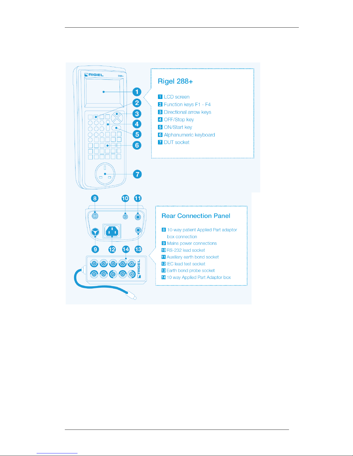
1.3. Interfaces __________________________________________________________ 10
1.4. Optional Accessories _________________________________________________ 11
1.5. Test ’n Tag Compatible _______________________________________________ 11
1.6. Unique use of ICONS _________________________________________________ 12
2. Logging on _____________________________________________________ - 13 -
3. Getting Started _________________________________________________ - 14 -
4. Automatic Mode ________________________________________________ - 15 -
4.1. Asset ID _________________________________________________________ - 15 -
4.2. Test Codes _______________________________________________________ - 15 -
4.3. Test Period _______________________________________________________ - 16 -
4.4. Trace Variables ___________________________________________________ - 16 -
4.5. Performing an Automatic Test: ______________________________________ - 16 -
4.5.1. Semi Automatic Test Mode __________________________________________ - 16 -
4.6. Failure Menu _____________________________________________________ - 27 -
4.7. Test ‘n Tag _______________________________________________________ - 27 -
4.8. Options Menu ____________________________________________________ - 27 -
4.9. View Results _____________________________________________________ - 28 -
5. Manual Mode __________________________________________________ - 29 -
5.1. Earth Continuity __________________________________________________ - 31 -
5.2. Insulation Resistance EUT ___________________________________________ - 33 -
5.3. Insulation Resistance Applied Parts ___________________________________ - 34 -
5.4. Insulation Resistance Applied Parts to Mains ___________________________ - 35 -
5.5. Equipment Leakage (Direct) _________________________________________ - 36 -
5.6. Equipment Leakage (Differential) ____________________________________ - 37 -
5.7. Equipment Leakage (Alternative) _____________________________________ - 39 -
5.8. Applied Part Leakage (Direct) ________________________________________ - 40 -
5.9. Applied Part Leakage (Alternative) ___________________________________ - 41 -
5.10. Earth Leakage Test ________________________________________________ - 43 -
5.11. Enclosure Leakage Test (mains powered) ______________________________ - 44 -
5.12. Point to Point Enclosure Leakage Test (battery powered) _________________ - 45 -
5.13. Patient Leakage ___________________________________________________ - 46 -
Page 6

Rigel 288 plus Instruction Manual – Revision 1.1 5
5.14. Patient Leakage – F-Type ___________________________________________ - 48 -
5.15. Patient Auxiliary Current ___________________________________________ - 49 -
5.16. Load Test ________________________________________________________ - 50 -
5.17. IEC Lead _________________________________________________________ - 51 -
6. Customising your tester __________________________________________ - 53 -
6.1. Test Sequences ___________________________________________________ - 53 -
6.1.1. User definable tests _________________________________________________ - 54 -
6.1.2. View, Delete or Copy an existing Test Routine. _________________________ - 54 -
6.1.3. Modifying (Edit) Existing Test Sequences ______________________________ - 55 -
6.1.4. Edit individual Test __________________________________________________ - 57 -
6.1.5. Insert an individual safety test ________________________________________ - 58 -
6.1.6. Insert a non-electrical safety test ______________________________________ - 59 -
6.1.7. Create a new Test Sequence _________________________________________ - 62 -
6.2. Test Codes _______________________________________________________ - 64 -
6.2.1. Create New Test Codes _____________________________________________ - 64 -
6.2.2. Configuring the Applied Part Module __________________________________ - 66 -
6.3. Asset Trace Variables ______________________________________________ - 69 -
6.4. System Config ____________________________________________________ - 70 -
6.4.1. Asset ID ___________________________________________________________ - 71 -
6.4.2. After Test __________________________________________________________ - 71 -
6.4.3. Comments _________________________________________________________ - 72 -
6.4.4. Applied Part Results ________________________________________________ - 72 -
6.4.5. Language __________________________________________________________ - 72 -
6.4.6. Check IEC lead Polarity _____________________________________________ - 72 -
6.4.7. Date / Time ________________________________________________________ - 73 -
6.5. Blue Tooth Favourites ______________________________________________ - 73 -
6.6. User Admin ______________________________________________________ - 77 -
6.6.1. Preferences ________________________________________________________ - 78 -
6.6.2. Change User _______________________________________________________ - 79 -
6.6.3. Change Password __________________________________________________ - 79 -
6.6.4. User Profile ________________________________________________________ - 80 -
6.7. Memory options __________________________________________________ - 80 -
6.8. Restore Factory Settings ____________________________________________ - 81 -
7. View Data _____________________________________________________ - 83 -
7.1. View Results _____________________________________________________ - 84 -
7.2. Search the database _______________________________________________ - 85 -
7.3. View Data Options ________________________________________________ - 86 -
8. Data Transfer __________________________________________________ - 87 -
8.1. Download to PC ___________________________________________________ - 87 -
8.2. Upload from PC ___________________________________________________ - 89 -
8.3. Configuration Data ________________________________________________ - 89 -
8.3.1. Send Config Data ___________________________________________________ - 89 -
8.3.2. Receive Config Data ________________________________________________ - 91 -
8.4. Clone Data _______________________________________________________ - 92 -
Page 7

Rigel 288 plus Instruction Manual – Revision 1.1 6
8.5. Load TnT Logo ____________________________________________________ - 92 -
9. About _________________________________________________________ - 94 -
10. Maintaining the Rigel 288 plus ___________________________________ - 95 -
10.1. Cleaning the Analyser ______________________________________________ - 95 -
10.2. User Maintenance _________________________________________________ - 95 -
10.3. Return Instructions. _______________________________________________ - 95 -
10 Technical Specifications __________________________________________ - 97 -
Appendix A Definition of IEC 60601 tests ______________________________ - 100 -
Appendix B Pass / Fail Limits of IEC 60601-1 ___________________________ - 107 -
Appendix D Pass / Fail limits of IEC 62353 _____________________________ - 113 -
Appendix E IEC 60601-1 Measuring Device ____________________________ - 114 -
Appendix F Firmware Route Map ___________________________________ - 115 -
Appendix G Available Application Notes ______________________________ - 116 -
Appendix H Connection diagram AP box ______________________________ - 117 -
Page 8
Rigel 288 plus Instruction Manual – Revision 1.1 7
User Notes
These operating instructions are intended for the use of adequately trained
personnel.
The following symbols are used in these operating instructions and on the Rigel 288
plus.
Warning of electrical danger!
Indicates instructions must be followed to avoid danger to persons.
Important, follow the documentation! This symbol indicates that the
operating instructions must be adhered to in order to avoid danger.
Warning, during many of the leakage tests the PROTECTIVE EARTH
CONDUCTOR to the appliance under test is interrupted. For this reason
additional means of protection are required in order to comply with the
relevant safety standards. For EN60601-1 leakage tests, it is recommended
that this additional protection is in the form of an isolation transformer,
with an isolated reference ground, used to power the entire system.
Do not connect any probe combination to the maximum permitted
voltage of 30 V AC/DC with respect to earth potential when
performing non-power tests. Danger of electric shock.
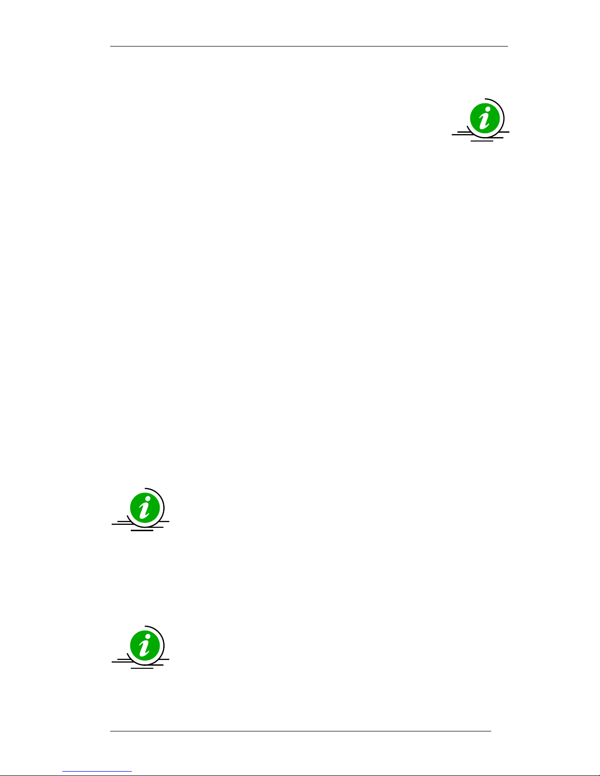
Symbol used for tips and guidance notes in this manual.
Application note(s) available see Appendix G.
Page 9
Rigel 288 plus Instruction Manual – Revision 1.1 8
1. Introduction
The Rigel 288 plus+ electrical safety analyzer offers an accurate and fast solution for
meeting international and local safety standards. Offering a complete range of tests
without the need for mains power, the 288 plus+ is capable of conducting batterypowered insulation and earth/ground bond testing as well as touch and point-to-point
leakage testing. This offers complete freedom to move around in often crowded rooms
during the installation process, eliminating the inconvenience of trailing mains cables.
The 288 plus+ has added two new insulation resistance tests (50VDC and 100VDC) to
complement the 250VDC and 500VDC insulation tests that were present in its
predecessor, the Rigel 288 plus. These new tests conform to growing manufacturer’s
test requirements for increasingly popular equipment running on 24VDC and 48VDC,
such as operating tables, lights and mobile X-rays.
Combining automatic and manual test sequences, data storage and direct printing
facilities, the Rigel 288 plus+ remains the most compact electrical safety analyzer of its
kind. Automatic warning of secondary earth/ground paths ensures users are made
aware when invalid readings are made, thus ensuring correct and accurate test results
first time, every time.
To further improve the portability and flexibility of the 288 plus+, a range of accessories,
including Bluetooth printers and barcode scanners are available.
The Rigel 288 plus+ is available in a wide range of power configurations to suit local
requirements, and conforms to several international standards including IEC 62353,
60601-1, NFPA-99 and many other local variants
The comprehensive database software, Med-eBase, ensures fast and easy download of
test results, straightforward management of asset databases, creation of test
sequences and the ability to produce professional test certificates.
1.1. Key Features
Versatile - Test in Accordance with the leakage requirements of
All-in-one compliance with international standards
including IEC / EN 62353, AAMI / IEC / EN
60601-1, IEC 61010, NFPA-99, AS / NZ 3551
Built-in electronic data storage and automated
testing reduce paperwork and saves time
Flexible user-definable test routines to meet the needs of your organisation
Small and compact with direct printing via Bluetooth connectivity
Battery-powered leakage, insulation and earth/ground bond tests enable faster
and more convenient testing
50 / 100 / 250 / 500 VDC insulation testing allows testing on equipment running
on 24VDC and 48VDC up to 253VAC
Automatic secondary verification ensures the correct result first time
Accurate high current, low energy bond testing
Page 10
Rigel 288 plus Instruction Manual – Revision 1.1 9
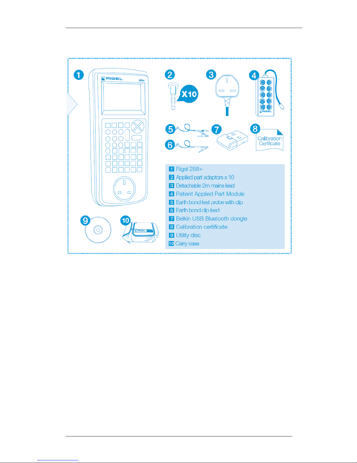
1.2. Rigel 288 plus includes:
Page 11
Rigel 288 plus Instruction Manual – Revision 1.1 10
1.3. Interfaces
Page 12
Rigel 288 plus Instruction Manual – Revision 1.1 11
1.4. Optional Accessories
Med-eBase PC Download software (p/n 301A920)
RS232 download cable (p/n 331A952)
Single Applied Part leakage lead (p/n 331A953)
Bluetooth Barcode scanner (p/n 339A923)
Bluetooth Test ‘N’ Tag Pro (p/n 339A980)
Bluetooth Test ‘N’ Tag Elite System (p/n 339A970)
10-way Applied part adaptor box (p/n 331A680)
1.5. Test ’n Tag Compatible
The Rigel 288 plus is compatible with the Seaward Test ‘n Tag and Elite system. Our
Test ‘n Tag systems allows you to print customised Thermal PASS / FAIL labels.
The benefits of using the Test ‘n Tag printers are:
Robust and durable labels
Resistant to most solvents used in the medical sector
Free opportunity to advertise your logo and company details or emergency
telephone number with every item you Test ‘n’ Tag.
Automatic barcode generation to provide easy use of the barcode scanner thus
speeding up your test time.
The unique Test ‘n’ Tag label provides test status and retest due date,
barcode and asset ID number, and person conducting the test. For more
information on using the Test ‘n Tag printer, see section 4.7.
Page 13
Rigel 288 plus Instruction Manual – Revision 1.1 12
1.6. Unique use of ICONS
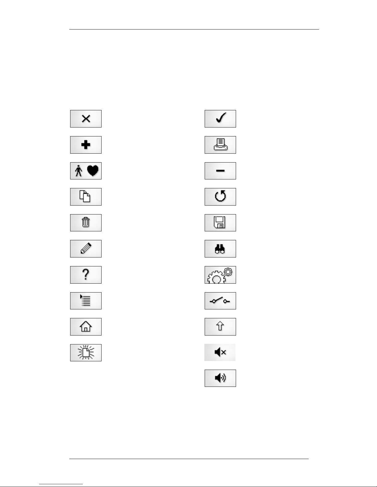
The Rigel 288 plus features a hi resolution graphic back lit display which not only
provides highly visible and easy to follow menu structures but also allows the user to
operate the tester using intuitive icons to speed up their test routines.
Below are of some of the icons used in the Rigel 288 plus:
Escape
Add
Applied Parts
Copy
Delete
Edit
Help
Menu – List
Home
New
OK – PASS
Print
Less
Repeat
Save
Search
Settings
Single Fault
Shift
Mute
Sound
Page 14
Rigel 288 plus Instruction Manual – Revision 1.1 - 13 -
2. Logging on
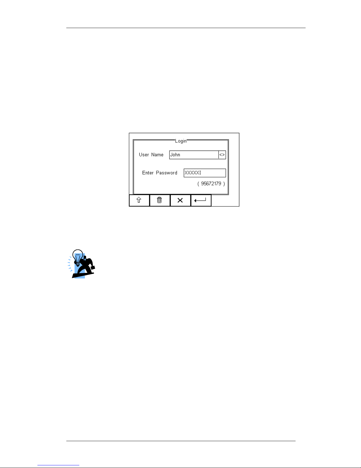
When switching on the Rigel 288 plus, the user will be able to log-in to allow for specific
default user preferences and to provide traceability of test results. To increase the
security and protection of the user, a password can be set prior to using the Rigel 288
plus. See 6.6.3 for further details. The default password setting is OFF and the login
screen will not require a password. In case a user and password are set, the tester will
default to the last user / password.
To change the user, use the drop down menu provided [<>] and select the new user. In
case a password is set for the new user, please enter the password (case sensitive).
In case a password is lost and the unit is blocked, please call our helpdesk
on: +44 (0) 191 5878701 or contact your local distributor and quote the 8digit code (shown below the password field) and the serial number of the
tester to allow a temporary password being created. For security reasons,
passwords can only be provided to the original purchaser of the device.
The Rigel 288 plus is designed to allow a user to customise test sequences and allow
default settings. This customisation can speed up testing by providing the user with
default manufacturer lists, model numbers, user text protocols, automatic printing posttext and fault menus.
Page 15
Rigel 288 plus Instruction Manual – Revision 1.1 - 14 -
3. Getting Started
1) Setting the correct language: See chapter 6.4.5
2) Setting the correct time and date: See chapter 6.4.7
3) Start automatic safety test See below
The Rigel 288 plus is pre-programmed to perform electrical safety tests in
accordance with a variety of international standards. To start an automatic safety
test, simply
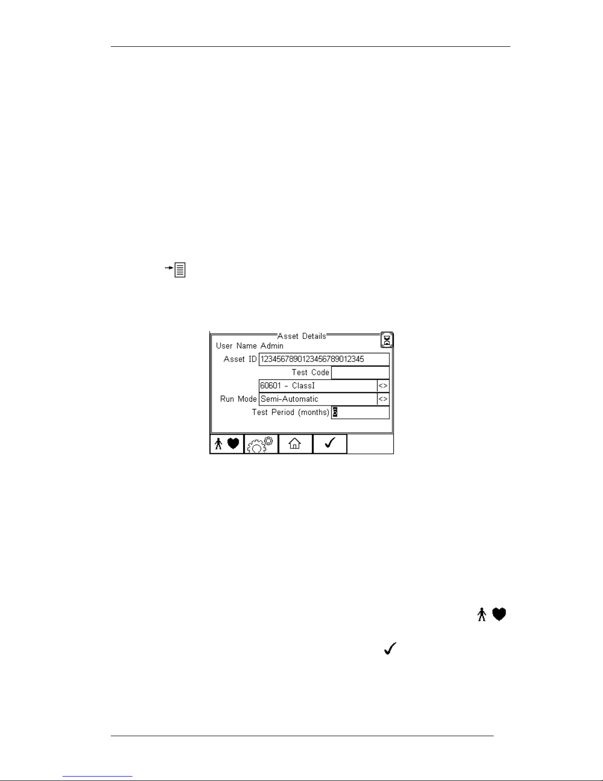
Press the button (F4) from the home screen and select Auto Mode. This
will show the Asset Details screen as detailed below;
Select the right criteria for the Satety Test from the Asset Details screen;
Enter the Asset ID number using the keypad or barcode scanner.*
Use the up, down, left and right keys to select the required default Test
Sequence
Select the Run Mode (Semi or Full Automatic) using the up, down, left
and right keys. See 4.5.1
Configure the Applied Part module when required by pressing the
button (F1). See 4.5 point 6
When all parameters are set, press the button (4) to enter
(optionally) information about the asset such as make model etc. See 4.4
for more details.
Page 16

Rigel 288 plus Instruction Manual – Revision 1.1 - 15 -
4. Automatic Mode
The Automatic mode provides the user with the ability to run a preset test sequence and
store the data afterwards.
4.1. Asset ID
Each test record is stored using the Asset ID number (25 character max) and date /
time of test. Multiple entries can be applied using the same Asset ID number. In this
case, the memory will hold all entries and differentiate using the test date.
The Asset ID field is used to store (and identify) the record in the Rigel
288 plus database. Additional input fields, referred to as ASSET TRACE
VARIABLES are available to distinguish between identical Asset ID
records, ie when the ASSET ID field is used to enter the Model,
description (ie “bed”, “ECG5” etc) or 4 digit fast code.
The benefit of using the Rigel 288 plus in this way is that similar items can be easily
retested using the same parameters. When an existing ASSET ID is entered in the 288
plus, the tester will automatically configure itself to re-perform the test without any
additional settings being required. Once the 288 plus has loaded the previous test
settings, the user can reconfirm the correct ASSET ID.
Example:
The user sets the Rigel 288 plus to test a hospital bed, when the correct test settings
are entered (test sequence, and applied parts, enter “bed” in the asset ID field.
Continue to the next screen and enter the “fixed” asset variables like description and
make model etc. Perform a full test. The next time you test a bed, enter “bed” in the
asset ID field and the 288 plus will automatically be configured to test that type of bed.
Then simply overwrite “bed” with the ASSET ID and your safety test will be saved under
the correct ID number. This can be repeated as long as the record “bed” is not deleted.
Identical ASSET RECORDS are also differentiated by TIME/DATE stamp, thus
ensuring no records are overwritten.
4.2. Test Codes
Instead of using the example above, users can also increase efficiency by using the 4digit Test Codes which allow the user to group certain Test Sequences with Applied
Part Configurations. See 6.2 more information on Test Codes.)
Test Sequence
The Rigel 288 plus comes standard with preset test routines to meet the requirements
of:
Page 17
Rigel 288 plus Instruction Manual – Revision 1.1 - 16 -
IEC 60601-1
IEC 62353
AAMi (US version)
NFPA-99 (US version)
VDE 0701 / 0702
IEC 61010 test sequences can be programmed. See Appendix G
for available application notes.
In addition, the user can create a total of 50 preset test sequences to meet local or
specific requirements. (See 6.1 more information on creating new test sequences)
4.3. Test Period
The re-test period allows the user to include the next test date on printed labels and PC
downloads that make it easier to schedule future work. More details on printing labels
see 4.2)
4.4. Trace Variables
To increase the traceability of the safety test, the user can include valuable data with
the test record such as Re-test period and Asset variables (see 6.3, 6.4.1 and 4.1 for
more information)
4.5. Performing an Automatic Test:
The automatic mode provides an option to test in full automatic or semi autoatic mode.
In full automatic mode, the Rigel 288 plus will step through the non powered tests and
once the powered tests (load and leakage tests) have started, all test conditions
including single fault conditions are executed automatically without the required
intervention of an operator.
See Application notes for suggestions when testing on isolated mains
supply or fixed installations.
4.5.1. Semi Automatic Test Mode
When testing Medical Devices, it is important that measurements are taken when the
Equipment Under Test (EUT) is fully operational (a requirement of IEC 60601-1 and
subsequent standards).
The Rigel 288 plus has a unique Semi Automatic Mode that allows
manual control of power-up and power-down of the EUT as well as
controlling the test sequence. This ensures that correct measurements
are performed and provide sufficient time to power-down any device
which is sensitive to power-breaks e.g. Ultrasound Equipment and PC
based ME Equipment.
Page 18
Rigel 288 plus Instruction Manual – Revision 1.1 - 17 -
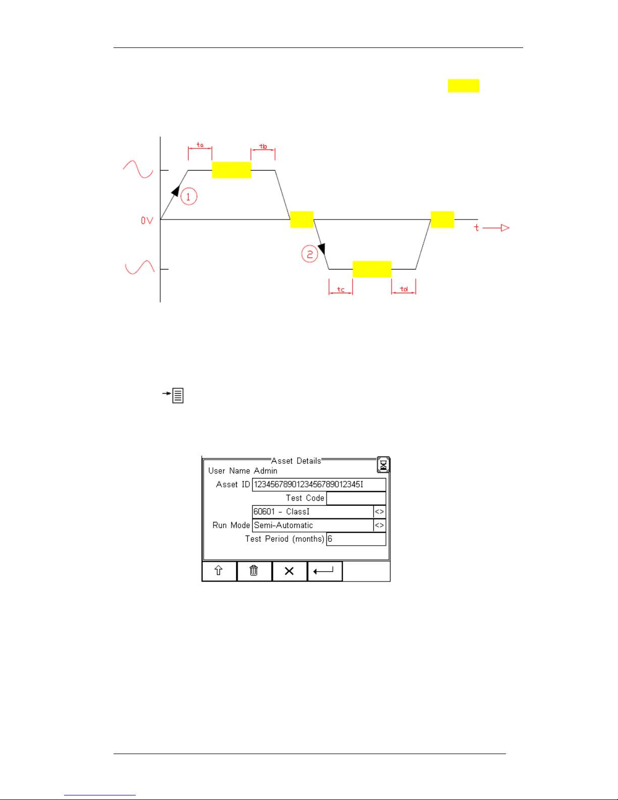
Below is a graph highlighting the Grouping of Single Fault Conditions (booox) and the
delays which are manually controlled by the User (ta, tb, tc & td) and the time in which the
safety analyser performs the automatic test routines.
The following procedures describe the setup and completion of an automatic test
sequence. The steps are applicable to all available test sequences. As example we
describe a typical automatic test to IEC 60601.
Press the button (F4) from the home screen and select Auto Mode. This will show
the Asset Details screen as detailed below;
Select the right criteria for the Satety Test from the Asset Details screen;
1. Enter the Asset ID number using the keypad or barcode scanner.
2. Enter the Test Code if this has been created (see 4.2)
3. Use the up, down, left and right keys to select the required Test Sequence
4. Select the Run Mode (Semi or Full Automatic) using the up, down, left and right
keys.
5. Enter the required test period in months.
Page 19
Rigel 288 plus Instruction Manual – Revision 1.1 - 18 -
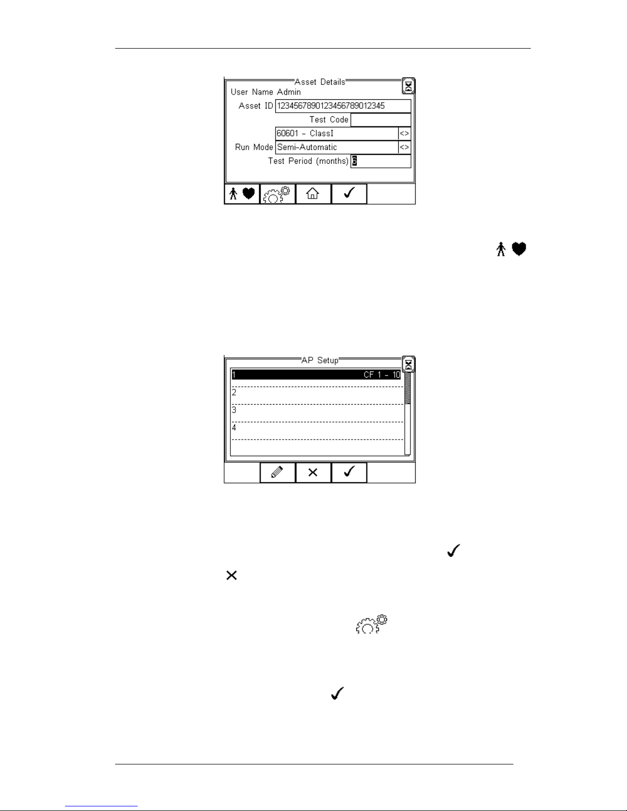
6. Configure the Applied Part module when required by pressing the
button (F1).
The following screen presents a default setup for:
10 x type CF (1..10)
To configure the Applied Part Module to meet your requirements, please see 4.5
for more information.
When the configuration has been completed, press the button (F4).
Pressing the button (F3) would return to the previous screen and lose
the settings.
7. Returning to the Asset Details screen, the button (F2) provides the user
with the option to modify or create a new Test Sequence from this menu. This
feature is identical to that of the Test Sequence feature in the Setup - Test
Sequence menu. (See 6.1 for more information)
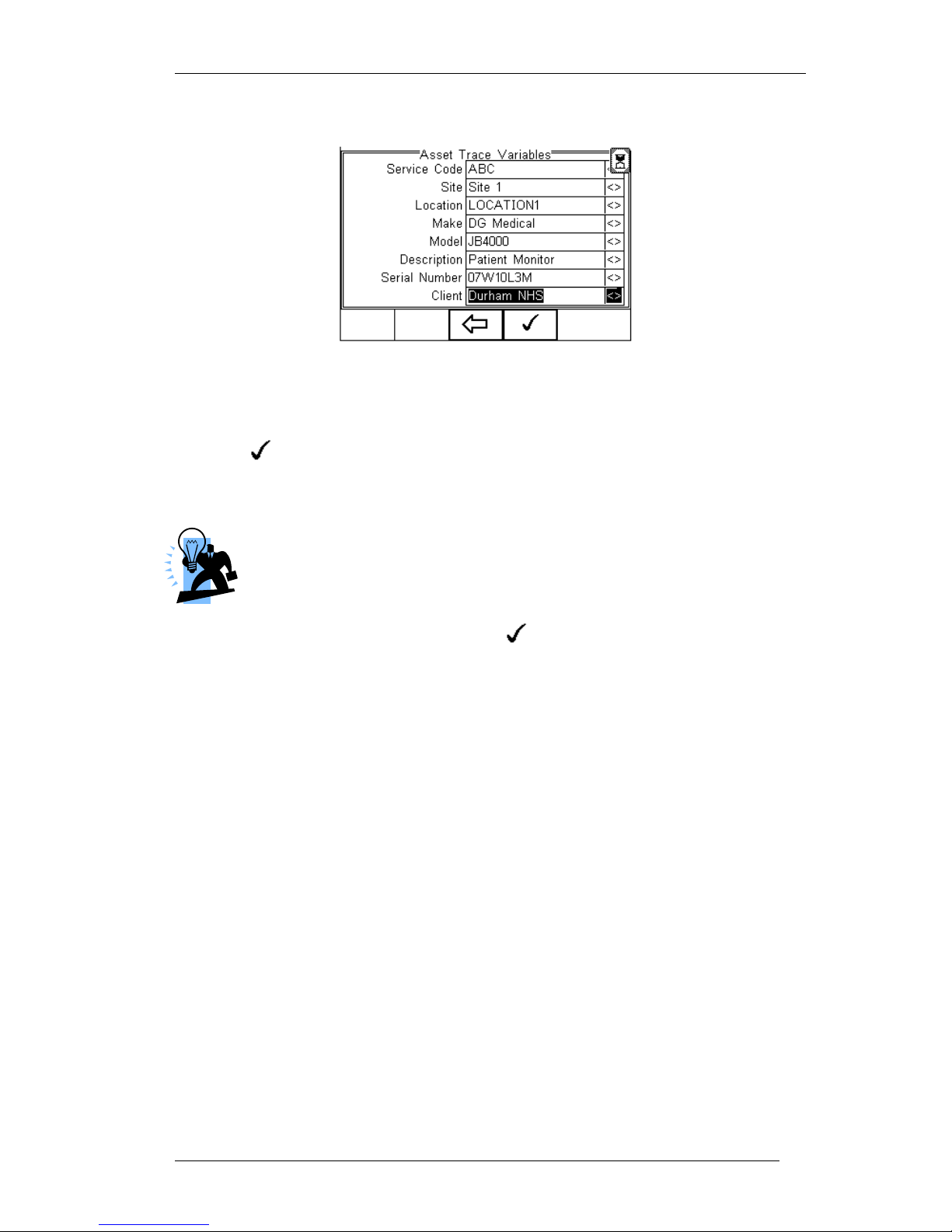
When all parameters are set, press the button (4) to enter the Asset Trace
Variables screen (when applicable). In this example, all Asset Variables are activated.
Page 20
Rigel 288 plus Instruction Manual – Revision 1.1 - 19 -
8. Use the Up & Down Keys to navigate the menu and the Left & Right Keys to
open the drop down boxes [<>]. Select the required input and confirm with the
button (F4). Each variable entered during the automatic test will
automatically be added to the list for future use. Trace Variables that are deactivated (set to NO in the Setup menu, section 6.3) will not appear during the
automatic tests.
A maximum of 40 individual entries are available for each Trace
Variable. Additional entries will overwrite on a first in first out basis.
When all information is provided, press the button (F4) to start the safety test.
To ensure the safety of the user, non-electrical tests are done prior to the powered
electrical safety tests.
Non-powered tests are deemed;
Visual and Custom tests (if applicable),
Earthbond test (class I)
Insulation test (if applicable)
In this example we will perform a safety test on Class I equipment, using a preset test
sequence, based on IEC 60601-1 with added Visual Test prior to the safety test and a
Custom Test followin the successful safety test.
The Applied Part Configuration is set to default and the test is executed in Semi
Automatic mode.
Page 21
Rigel 288 plus Instruction Manual – Revision 1.1 - 20 -
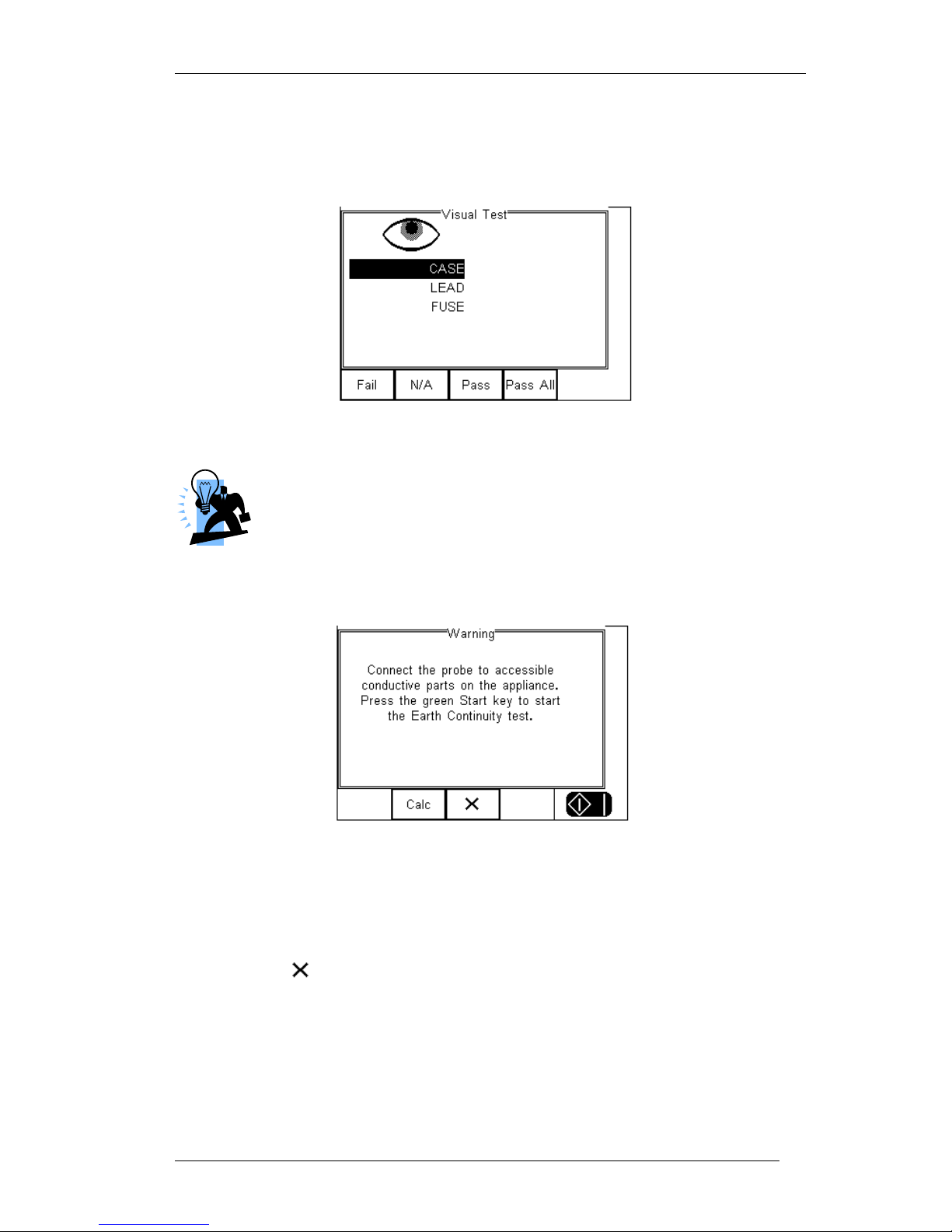
Visual Test
This is the first test in the test sequence;
Press the corresponding appropriate button to select the outcome of the visual test.
Custom Visual tests can be created. See 6.1.6 for more information.
If one or more Visual tests result in a failure, a Failure menu will
appear.
Provided the test has Passed, the next test will be the Earth Continuity
Attention! Ensure the earth bond test lead is connected to the lower (black) 4 mm
socket when testing between probe and EUT earth.
Press the Calc button (F2) to calculate the pass fail limit based on the type of cable
(mm²) and cable length.
Pressing the button (F3) will bring up the failure menu (see 4.6)
Press the Green start key to start the earth continuity test.
Page 22
Rigel 288 plus Instruction Manual – Revision 1.1 - 21 -
Caution, never connect the Earth Bond Probe to voltages in excess of 30V
since this can cause damage to the equipment.
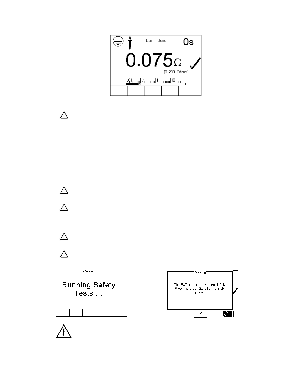
The earth bond test screen provides both a digital read-out as well as a bar-graph
indication. In addition, the test duration (top right corner), limit (0.200 Ohms) and Tick
mark are provided to demonstrate the test has passed.
If the test fails, the failure menu will be displayed. See 4.6
Once the non-powered tests have been completed, the user is warned that the EUT is
about to be switched on.
Warning – never leave the earth bond, or any other probe attached to any
moving parts.
Warning – never touch the appliance under test whilst testing is in
progress. Doing so could result in injury due to electric shock and / or
sudden movement of any mechanical parts on the appliance.
Refer to page 8 for notes on precautions required for compliance with the
relevant safety standards.
Do not exceed the maximum permitted voltage of 30 V AC/DC
with respect to earth potential! Electric Shock danger!
Warning Mains voltage applied to appliance.
Page 23
Rigel 288 plus Instruction Manual – Revision 1.1 - 22 -
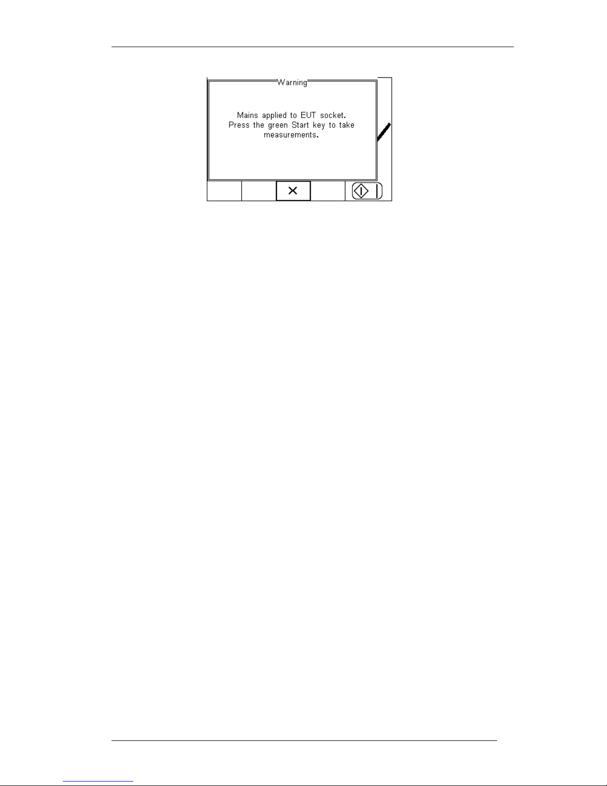
This example uses the Semi Automatic Mode and the user has the opportunity to
determine the moment at which the leakage measurements start. In fully automatic
mode , the Rigel 288 plus will start the measurements immediately after the EUT has
been switched on.
The initial powered test is a load test. The Rigel 288 plus will check for a short circuit
EUT and ensure the applied load (EUT) is less than 16 A.
In case of a short circuit in the EUT, the Rigel 288 plus will not power-up and a warning
message is displayed.
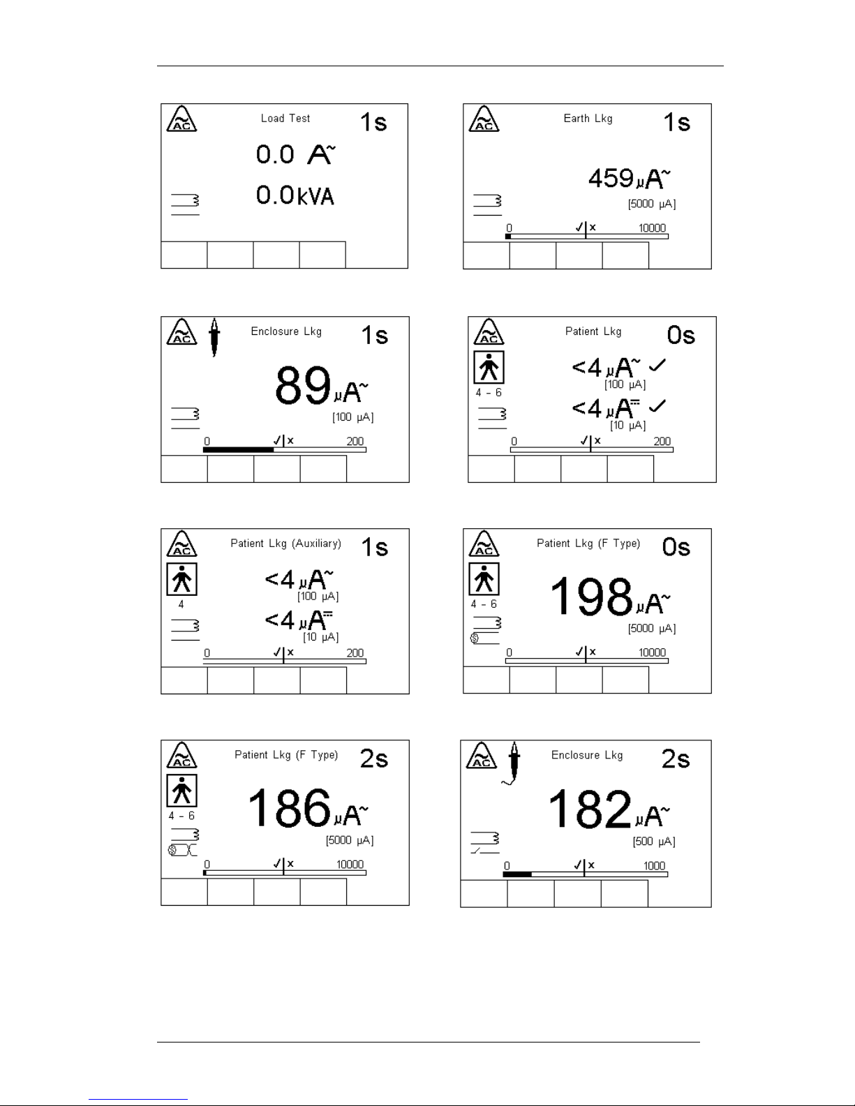
Following the Load Test, the individual leakage tests are polled, displayed and
measured.
Note that all leakage measurements are grouped by Single Fault Condition (SFC)
As such, all leakage measurements are carried out for a specific SFC, leakage
measurements are then repeated for the next SFC. This is to minimise the power
breaks and power ups. By grouping the SFC’s, the Rigel 288 plus is able to perform a
full IEC 60601-1 test, only requiring two power breaks.
The sequence of Single Fault Conditions is;
1. Normal Supply
2. Normal Supply Open Earth SFC (for Class I equipment only),
3. Normal Supply Open Neutral (Power Break),
4. Reversed Supply (Power on),
5. Reversed Supply Open Earth, (for Class I equipment only),
6. Reversed Supply Open Neutral (Power Break)
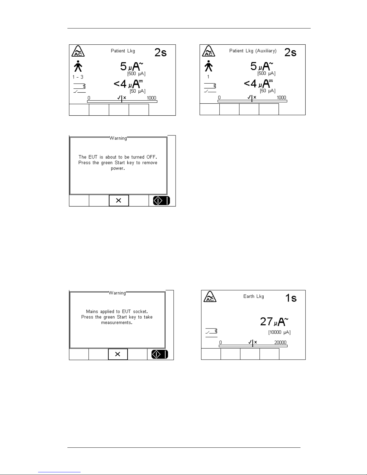
The applicable SFC is displayed in the bottom left side of the display. The following is a
typical sequence for a class 1 device.
Page 24
Rigel 288 plus Instruction Manual – Revision 1.1 - 23 -
Page 25
Rigel 288 plus Instruction Manual – Revision 1.1 - 24 -
Now the test sequence requires to open the Neutral which will result in a power break.
The Semi Automatic mode provides the user with a warning and requires a confirmation
prior to interrupting the Neutral. This allows the user to properly power down the
Medical Device and prevent possible damage caused by interupting the power supply.
Note that this message is not available in full automatic mode. The Rigel 288 plus will
continue with all warning open neutral measurements.
Page 26
Rigel 288 plus Instruction Manual – Revision 1.1 - 25 -
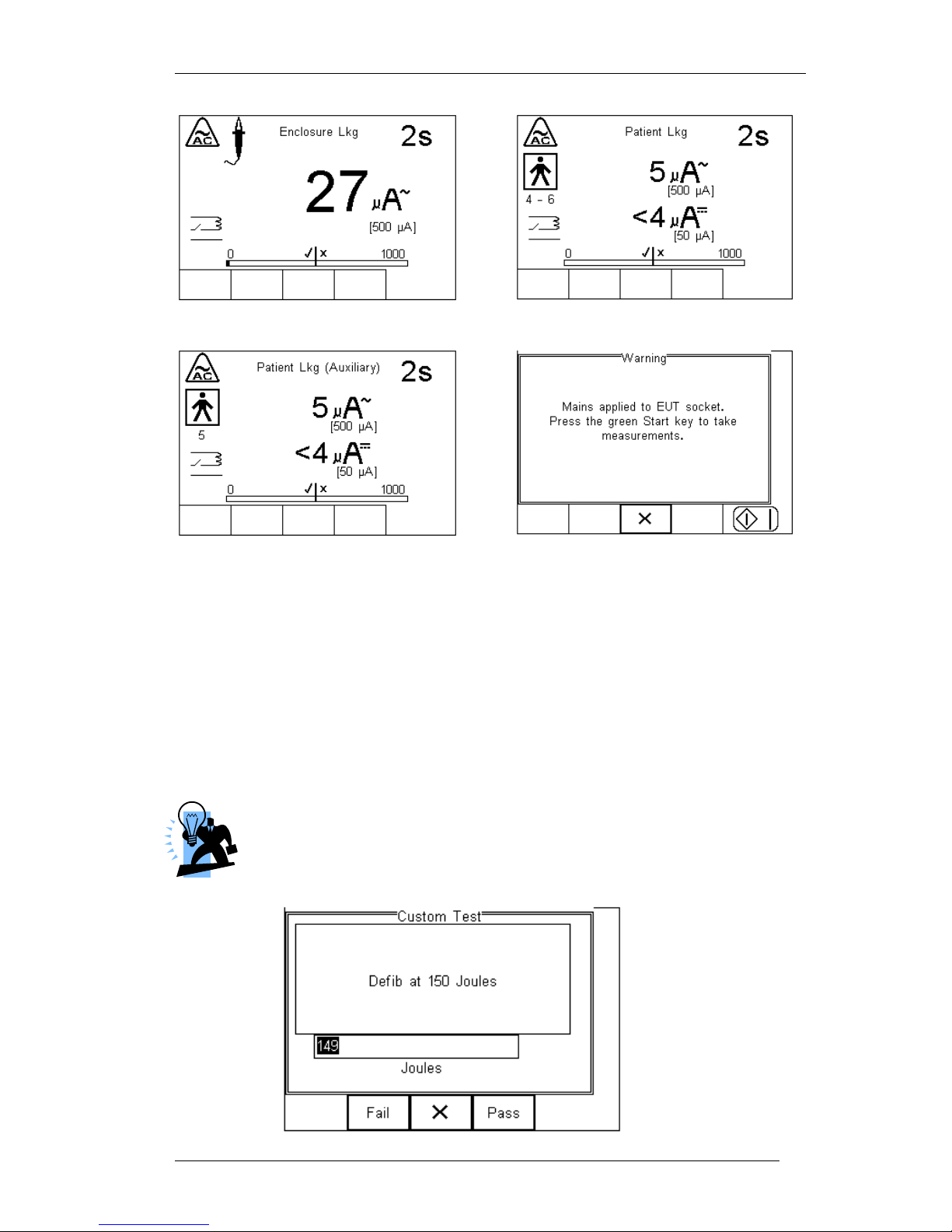
The next step is to reverse the power supply. The Rigel 288 plus will automatically
reverse the power and start the test sequence again. In the semi automatic mode, the
user can determine when the measurements start. In full automatic mode, the power
reversal is instant and measurements will start directly after mains reversal.
Following the safety tests, the user is able to store additional information within the test
record such as performance of the medical device. See 6.1.6 for more on creating nonelectrical safety tests.
In this example we used a defib test. Simply enter the reading from the defibrillator
tester in the field provided. Then determine whether the test has passed or failed.
Additional customer tests (each 255 characters max) can be added to the test
program to provide a comprehensive test record combing visual tests with
safety and performance tests.
Page 27
Rigel 288 plus Instruction Manual – Revision 1.1 - 26 -
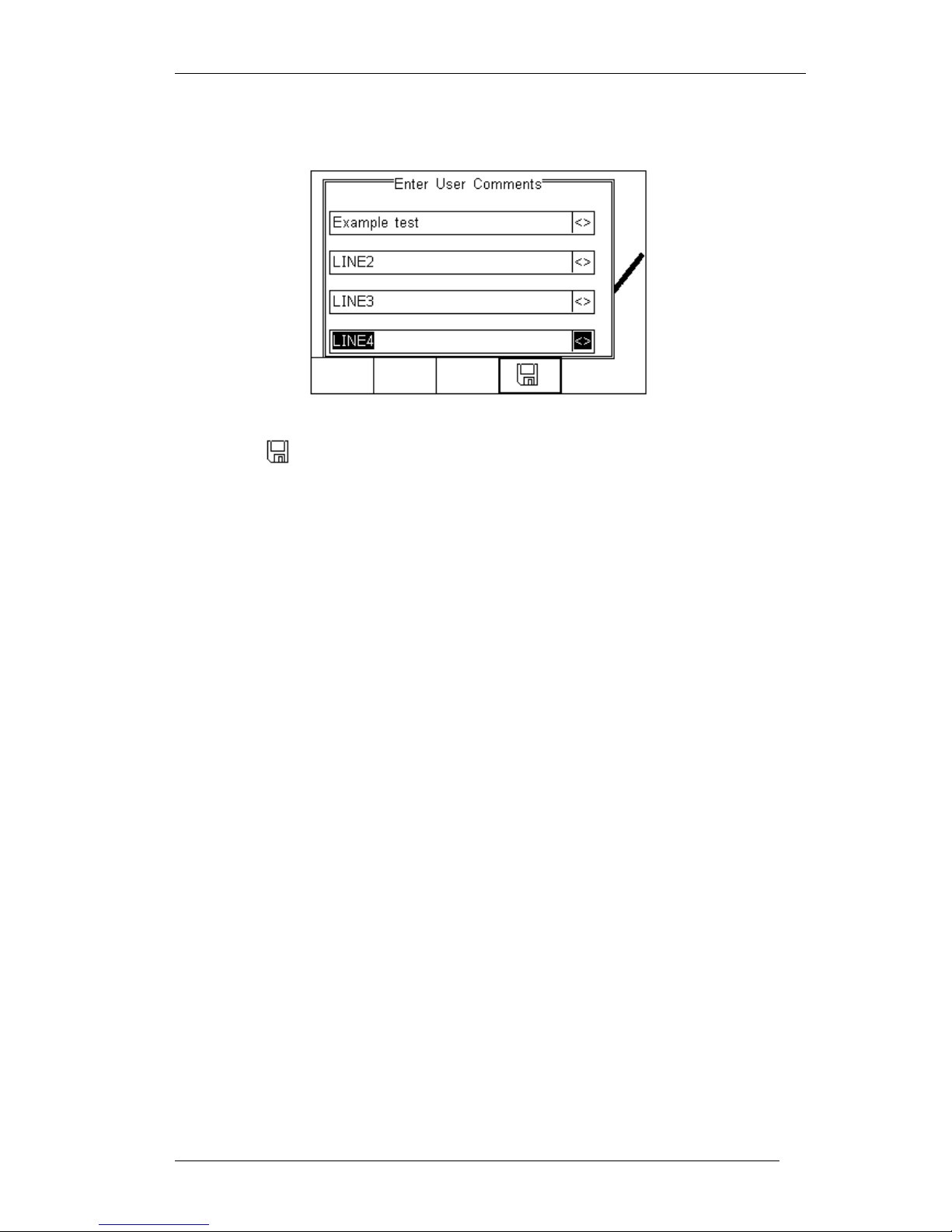
At the end of the test, the user has the ability to enter comments. See 6.4.2 for more
information on how to activate comments after a test.
Press the button (F4) to store the comments.
Depending on the settings in Menu - Setup - System Config (see 6.4) , a number of
After Test options are possible;
New Test – Automatically brings up the next test screen.
No further options or viewing of results available
Download – Automatically down loads the test results to the PC (see 8.1)
No further options or viewing of results available. The tester will return to the
home screen.
Print Label – Automatically prints the test results to a thermal printer.
No further options or viewing of results available. The tester will return to the
home screen.
Test ‘n Tag – Automatically prints a Test ‘n Tag lable. (see 4.7)
No further options or viewing of results available. The tester will return to the
home screen.
Options Menu – Provides a menu to allow further choices after a test. (see 4.8)
Page 28
Rigel 288 plus Instruction Manual – Revision 1.1 - 27 -
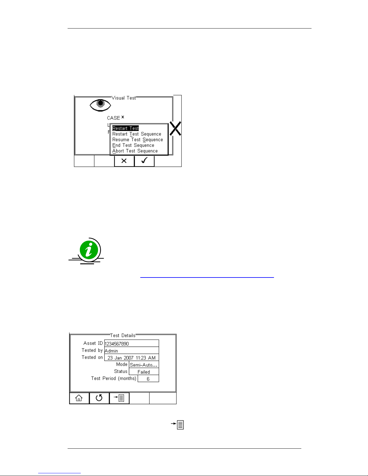
4.6. Failure Menu
When a specific test fails, the user will be provided with a number of options depending
on the nature of the fault. The Failure Menu will enable the user to:
Restart Test (Individual test)
Restart Test Sequence (Whole Test
sequence)
Resume Test (Skip the failed test)
End Test Sequence (store result
and follow options. See 4.8)
Abort Test Sequence (no
information stored, return to home
screen)
4.7. Test ‘n Tag
The Rigel 288 plus is compatible with the Seaward Test ‘n Tag and Test ‘n tag Elite
system To use the Test ‘n Tag printer, add your T’nT printer to the Bluetooth Favorites.
See 6.5
A detailed application note is available from the Rigel website on the
used of Test’ n Tag printers with the Rigel 288 plus.
Please visit; http://www.rigelmedical.com/rigel-downloads
4.8. Options Menu
When Options has been selected in the Setup - System Config menu, the Rigel 288
plus will show a Test Details screen, see below.
The test screen provides the following
features;
Go to the home screen (F1)
Continue with the next test (F2)
Options (F3)
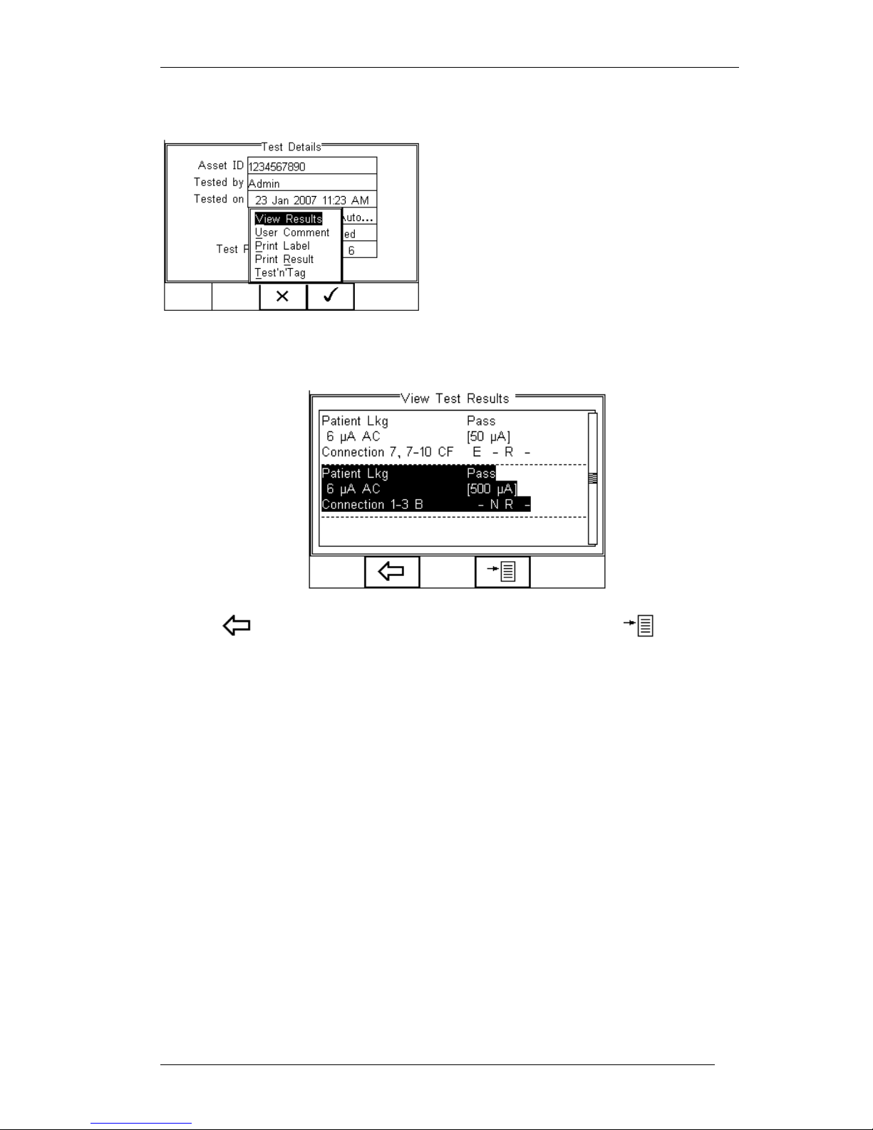
To view the options menu, select the button (F4) from the test details screen;
Page 29
Rigel 288 plus Instruction Manual – Revision 1.1 - 28 -
The options menu provides the following sub menu:
View Results will display the results of the
test (see section 4.9)
User Comment will allow the user to enter
comments if required
Print Label will print a pass/fail label on the
thermal printer (50 mm roll)
Print Result will print the result on the
thermal printer (50 mm roll)
Test ‘n Tag will produce a thermal transfer
Pass Fail label. (see 4.7)
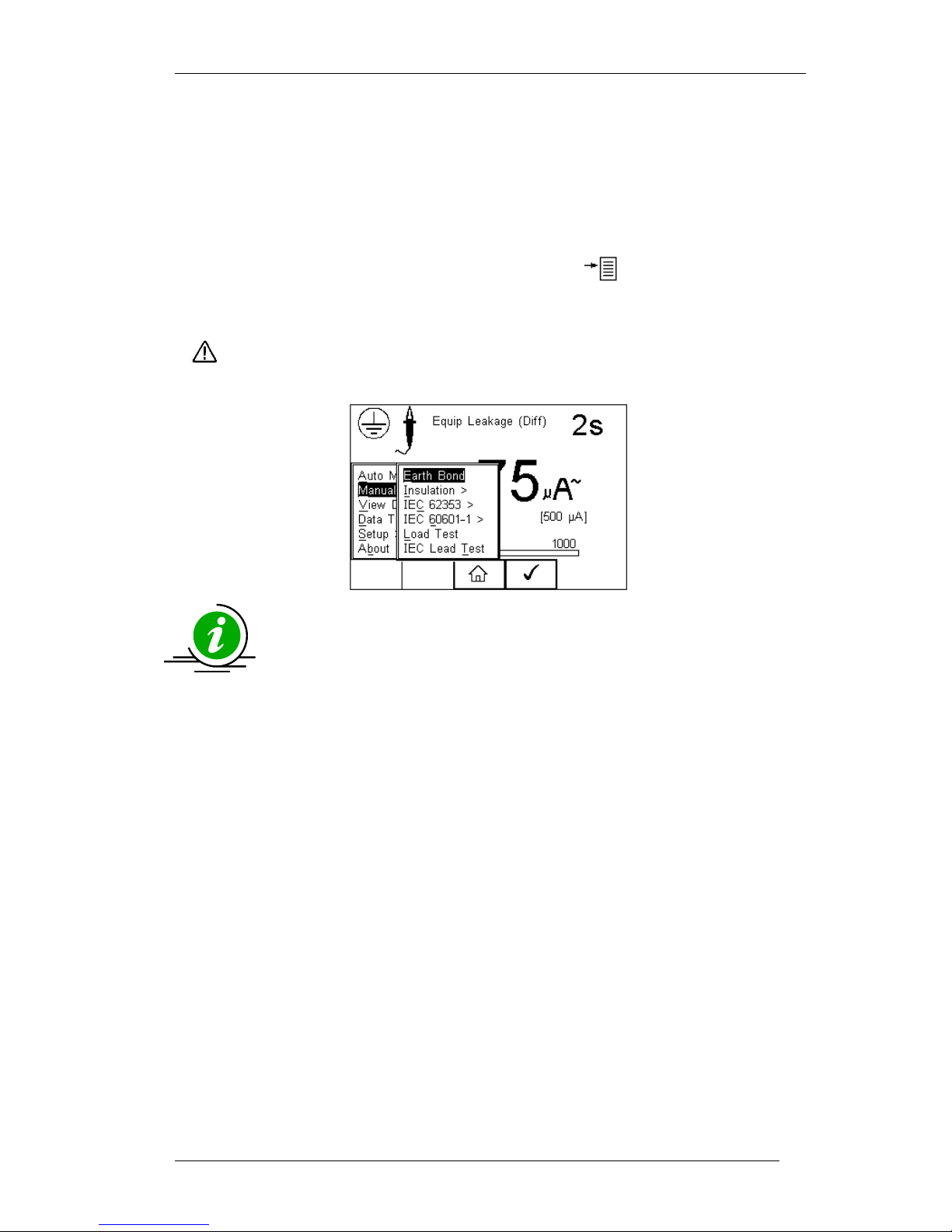
4.9. View Results
Use the button (F2) to return to the Test Details screen. The button (F4)
provides extra option to print results, label or Test ‘n tag
Page 30
Rigel 288 plus Instruction Manual – Revision 1.1 - 29 -
5. Manual Mode
The Manual mode provides the user with the features of testing a specific
individual test and or test condition for example to aid fault diagnostic
procedures. Manual tests are available from the home screen. Use the Left &
Right Keys to scroll through the various manual tests.
Manual tests can also be chosen, by pressing the button (F4) and select
Manual Mode from the list. See below.
Do not connect any probe combination to voltages in excess of 30
V AC/DC with respect to earth potential when performing nonpower tests. This can cause damage to the equipment.
Below is a map showing where the individual tests can be selected
in the Manual Mode menu.
Manual Mode >
Earth Bond
Insulation >
Insulation EUT
Insulation AP
Insulation AP to mains
IEC 62353 >
Equipment Leakage >
Direct
Alternative
Differential
AP Leakage Test >
Direct
Alternative
IEC 60601-1>
Earth leakage
Enclosure Leakage
Patient Leakage
Patient Lkg (Auxiliary)
Patient Lkg (F-Type)
Load test
IEC lead test
Page 31
Rigel 288 plus Instruction Manual – Revision 1.1 - 30 -
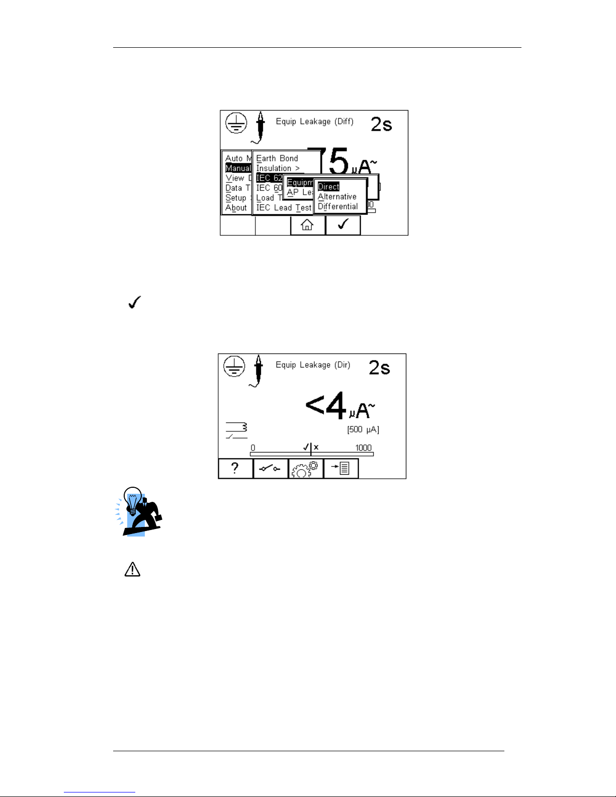
For example; To select an IEC 62353 - Equipment Leakage - Direct Method;
Use the Up, Down, Left and Right keys to navigate through the menu and press the
button (F4) to confirm.
The following manual mode screen appears;
The centre of the analogue bar graph indicates the limit value (in this case
500µA)
Warning, during many of the leakage tests the PROTECTIVE EARTH
CONDUCTOR to the appliance under test is interrupted. For this reason
additional means of protection are required in order to comply with the
relevant safety standards. For EN60601-1 leakage tests, it is recommended
that this additional protection is in the form of an isolation transformer,
with an isolated reference ground, used to power the entire system.
The screen shows the current measuring condition, ie;
Equipment Leakage (Direct Method)
2 second test duration
limit is [500µA]
Page 32
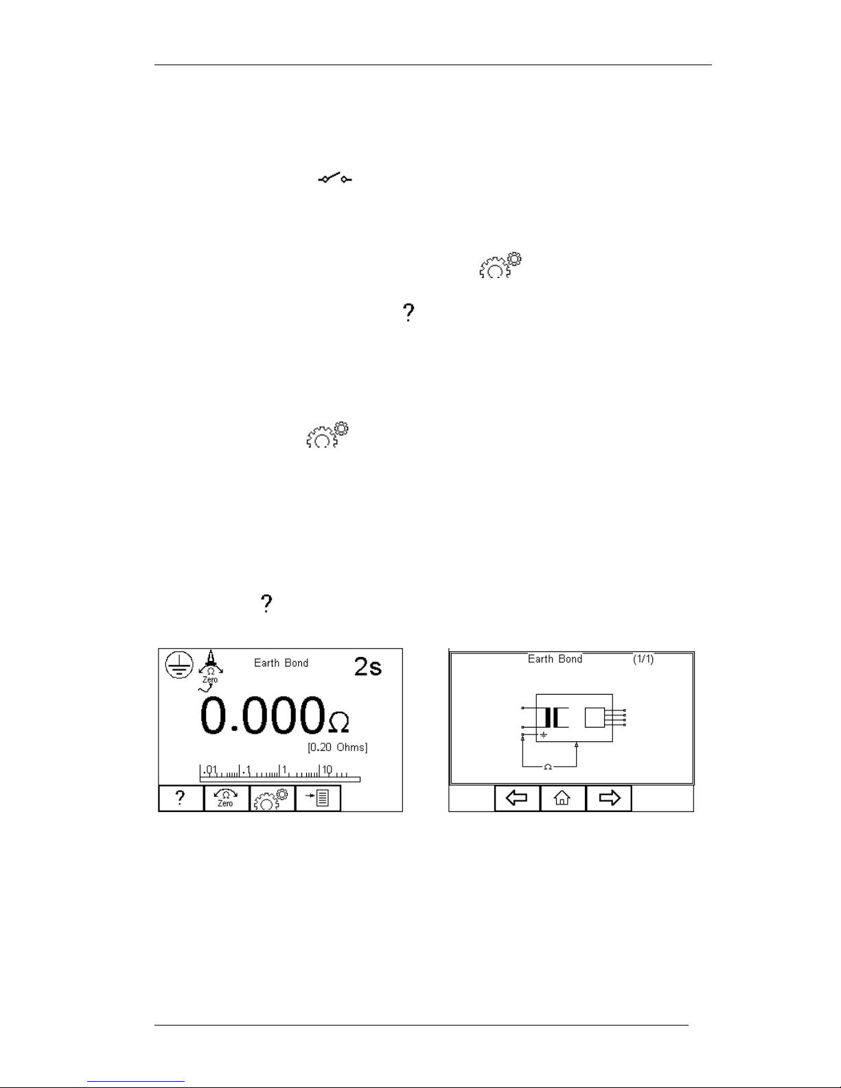
Rigel 288 plus Instruction Manual – Revision 1.1 - 31 -
Single Fault Condition (normal polarity – open earth)*
Class 1 and enclosure probe symbol
* The IEC 62353 specifies that the Direct Method measurement is done using an
interrupted earth. The button (F2) will only reverse the power supply.
All manual tests can be modified to meet user requirements. To change the
settings in the manual mode, simply press the button (F3).
Help is available by pressing the button (F1) in the form of a schematic
representation of the test.
Depending of the type of test, the F2 key is either used to select the test class
(Class I or II) or to set the single fault conditions. In the latter case, the test class
can be set within the menu button (F3).
5.1. Earth Continuity
This test is applicable to Class I equipment only.
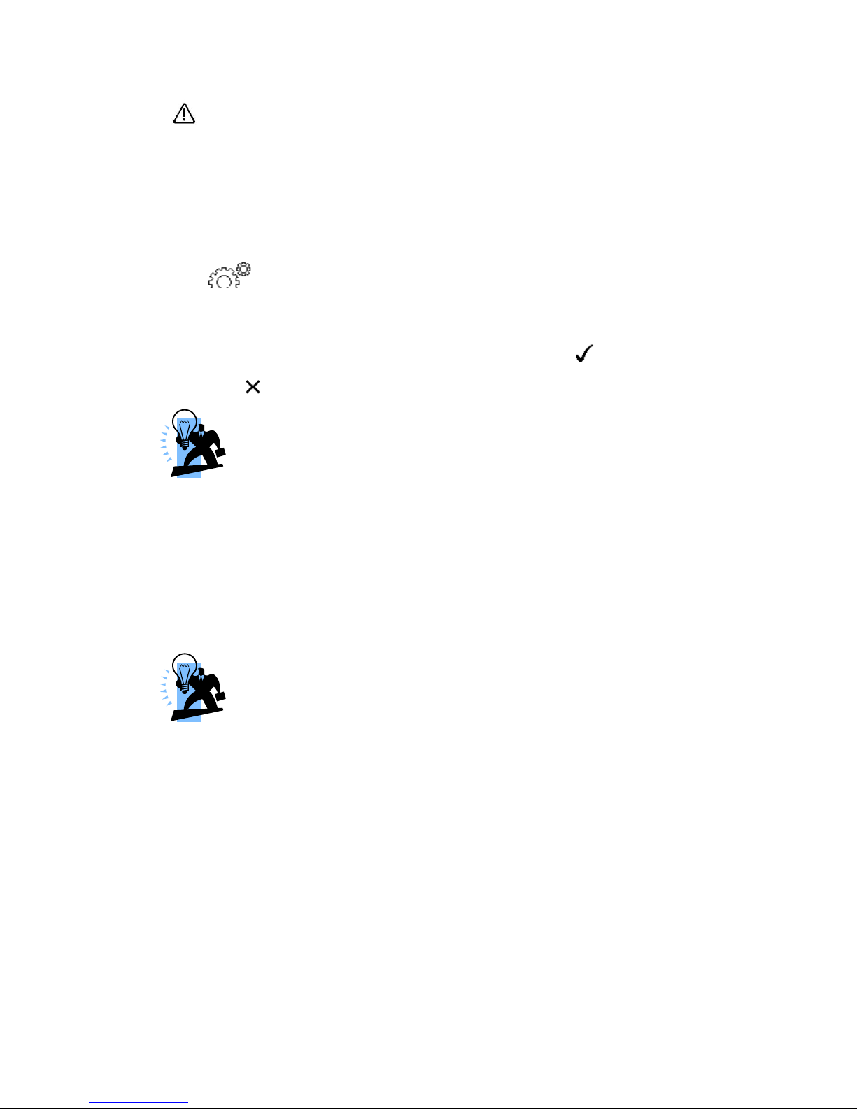
Press the F1 button to obtain the schematic representation of this test:
If an earth bond lead other than that supplied with the Rigel 288 plus is to be used then
any resistance associated with this lead can be zeroed out by connecting the supplied
earth bond lead to the EUT earth socket on the Rigel 288 plus and pressing the zero
button (F2). If the zero function has been activated then the zero icon overwrites the
single probe icon in the top left of the display. By preventing the zero button (F2) again
this function is cancelled.
Page 33
Rigel 288 plus Instruction Manual – Revision 1.1 - 32 -
Do not exceed the maximum permitted voltage of 30 V AC/DC
with respect to earth potential! Electric Shock danger!
This test will check that the connection between the earth pin in the mains plug of the
appliance and the metal casing of the appliance is satisfactory and of sufficiently low
resistance.
A DC test current of ±200mA is applied between the earth pin of the mains supply plug
and the earth bond test lead clip/probe. The worst-case result is shown on the display.
Press button (F3) to set the Test Duration and Pass/Fail limit. Use the up,
down, left and right keys to highlight, set, test duration and pass/fail limit. The pass/fail
limit can be calculated whilst in this mode by pressing (Calc) (F3). Enter the cross
sectional area and length of cable and a new limit will be calculated. This can be
overridden by selecting the continuity limit from the list. Press button (F4) when
complete. button (F3) will exit Settings mode without saving changes.
Switching off the Rigel 288 plus will not cancel the ‘probe zero’
Fit the Appliance mains plug into the EUT socket. Connect the Earth Bond lead to the
appliance metal part. Press the green START key to begin the test. The test will run for
a pre-set test duration. To end the test before the test time has expired, press the red
STOP key.
This test can also be used to test the earth bond resistance within an IEC power lead.
Connect the IEC power lead between the EUT power socket and IEC socket on the rear
panel of the Rigel 288 plus and commence the test.
The Rigel 288 plus display will show real time measurements during
an Earth Continuity test however, the highest reading is recorded
during the test. This can be used to detect momentary break in the
earth path e.g. damaged power cords or loose mains plug
connections. A Pass or Fail is determined by comparing the peak
value measured during the test with the pre-set continuity limit.
.
Page 34
Rigel 288 plus Instruction Manual – Revision 1.1 - 33 -
5.2. Insulation Resistance EUT
This test is applicable to all Class I and Class II equipment, typically used as part of
MDA DB 9801 and IEC 62353 test routines.
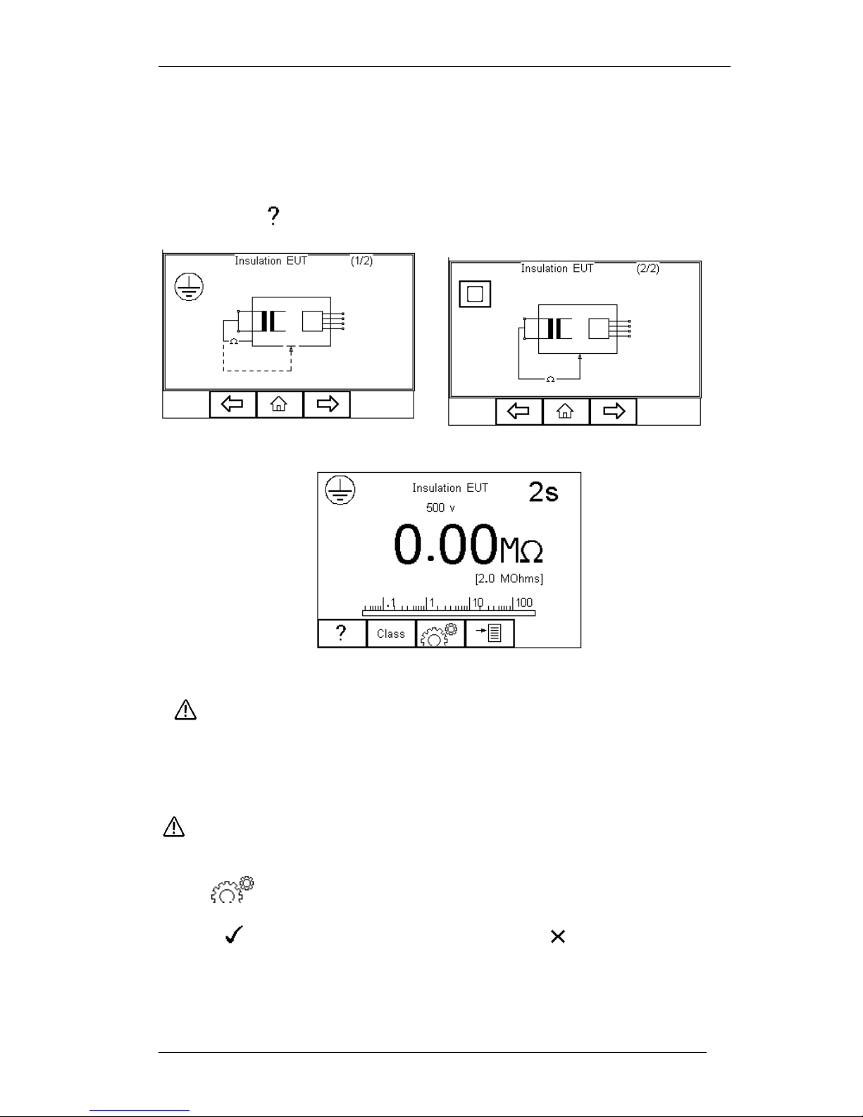
Press the F1 button to obtain the schematic representation of this test:
Do not exceed the maximum permitted voltage of 30 V AC/DC
with respect to earth potential! Electric Shock danger!
This test is used to verify that the mains supply pins are adequately insulated from earth
(Class I) or the enclosure (Class II).
During this test, 500V D.C. is applied between the earth pin and both the live
and neutral pins of the appliance mains supply plug.
Press button (F3) to set the Test Duration, Insulation test voltage (500 /
250VDC) and Pass/Fail limit. Use the up, down, left and right keys to highlight and set.
Press button (F4) when complete. Pressing button (F3) will exit
Settings mode without saving changes.
Press the class button (F2) to set the class of the appliance under test. For a class II
appliance the probe symbol will be displayed at the top of the LCD display.
Page 35
Rigel 288 plus Instruction Manual – Revision 1.1 - 34 -
For both Class 1and Class II appliances fit the Appliance mains plug into the EUT
socket. For Class 2 appliances only connect the Earth Bond lead to the appliance.
Press the green START key to begin the test. The test will run for the duration set or
until the red STOP key is pressed.
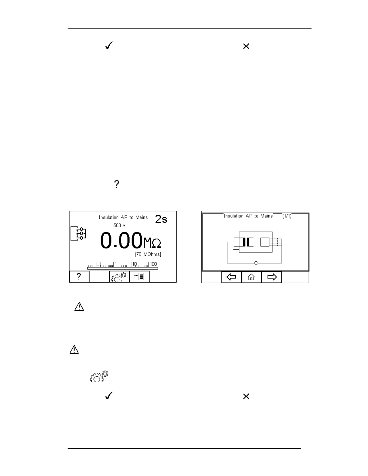
5.3. Insulation Resistance Applied Parts
This test is applicable to Class I and Class II BF and CF equipment only, typically used
as part of MDA DB 9801 and IEC 62353 test routines.
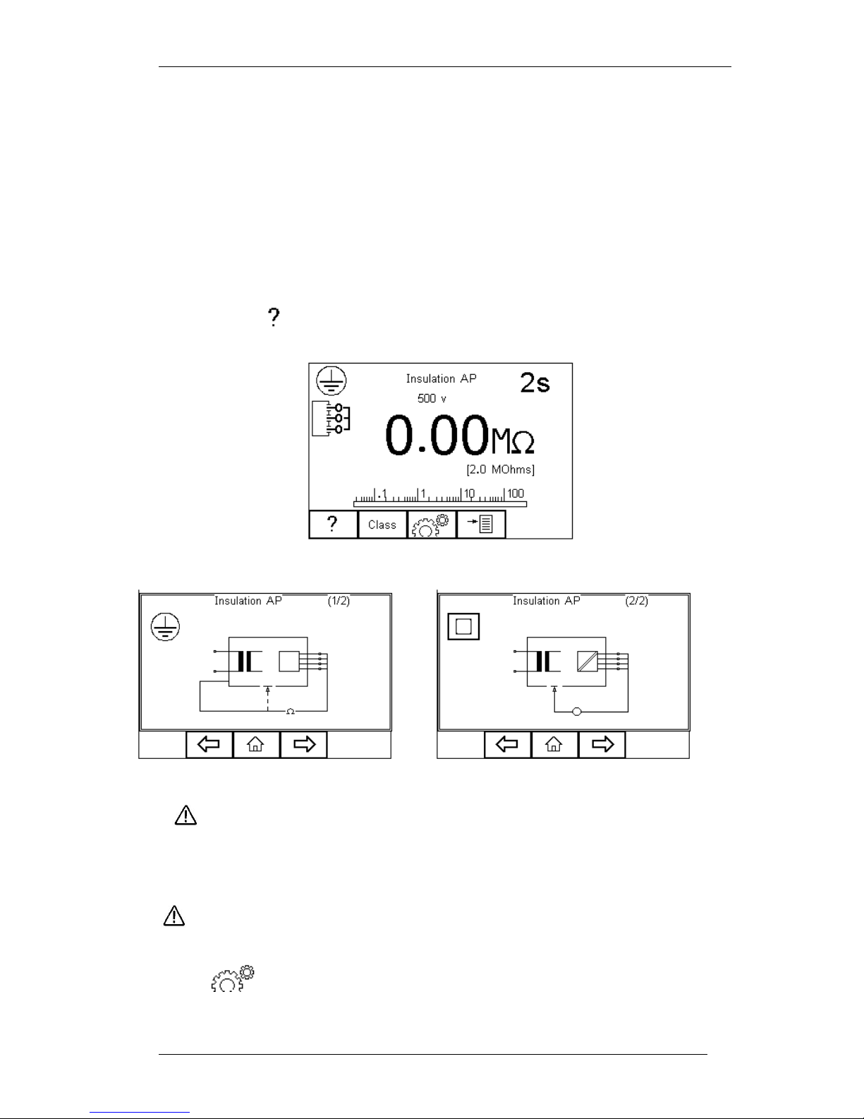
Press the F1 button to obtain the schematic representation of this test:
Do not exceed the maximum permitted voltage of 30 V AC/DC
with respect to earth potential! Electric Shock danger.
This test is used to verify that the Applied Parts are adequately insulated from earth
(Class I) or the enclosure (Class II).
During this test, 500V D.C. is applied between the earth pin (Class I) or the
enclosure (Class II) and all the Applied Parts combined.
Press button (F3) to set the Test Duration, Insulation test voltage (500 /
250VDC) and Pass/Fail limit. Use the up, down. left and right keys to highlight and set.
Page 36
Rigel 288 plus Instruction Manual – Revision 1.1 - 35 -
Press the button (F4) when complete. Pressing the button (F3) will exit
the Settings mode without saving changes.
Press the class button (F2) to set the class of the appliance under test. For a class II
appliance the probe symbol will be displayed at the top of the LCD display.
For both Class 1and Class II appliances, connect the Patient Connections or Applied
Parts to the Applied Part Module and fit the Appliance mains plug into the EUT outlet.
For Class 2 appliances only connect the Earth Bond lead to the appliance. Press the
green START key to begin the test. The test will run for the duration set or until the red
STOP key is pressed.
5.4. Insulation Resistance Applied Parts to Mains
This test is applicable to Class I and Class II BF and CF equipment only, typically used
as part of IEC 62353 test routines.
Press the F1 button to obtain the schematic representation of this test:
Do not exceed the maximum permitted voltage of 30 V AC/DC
with respect to earth potential! Electric Shock danger.
This test is used to verify that the Applied Parts are adequately insulated from the
mains parts.
During this test, 500V D.C. is applied between all the Applied Parts
combined and both the live and neutral pins of the appliance mains supply
plug.
Press button (F3) to set the Test Duration, Insulation test voltage (500 /
250VDC) and Pass/Fail limit. Use the up, down, left and right keys to highlight and set.
Press the button (F4) when complete. Pressing the button (F3) will exit
Settings mode without saving changes.
For both Class 1and Class II appliances, connect the Patient Connections or Applied
Parts to the Applied Part Module and fit the Appliance mains plug into the EUT outlet.
Page 37
Rigel 288 plus Instruction Manual – Revision 1.1 - 36 -
Press the green START key to begin the test. The test will run for the duration set or
until the red STOP key is pressed.
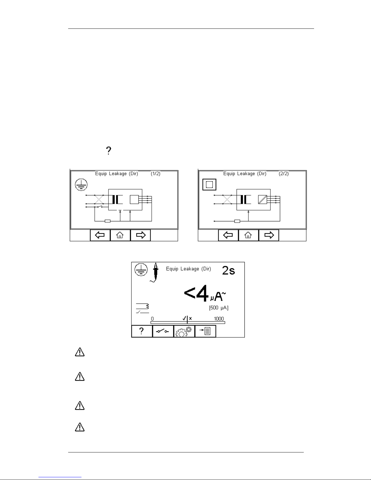
5.5. Equipment Leakage (Direct)
The Equipment Leakage Test measures the total leakage deriving from the Applied
Parts, Enclosure and Mains Parts combined to real earth.
This test is applicable to Class I and Class II B, BF and CF equipment. This is an IEC
62353 test. For a complete description of this test and applicable pass / fail limits,
please see Appendix C & D.
Press the button (F1) to obtain the schematic representation of this test:
Warning – never leave the earth bond, or any other probe attached to any
moving parts.
Warning – never touch the appliance under test whilst testing is in
progress. Doing so could result in injury due to electric shock and / or
sudden movement of any mechanical parts on the appliance.
Refer to page 8 for notes on precautions required for compliance with the
relevant safety standards.
Do not exceed the maximum permitted voltage of 30 V AC/DC
with respect to earth potential! Electric Shock danger!
Page 38
Rigel 288 plus Instruction Manual – Revision 1.1 - 37 -
Press button (F3) to set the Test Duration, and RMS Pass/Fail limit. Use the
arrow keys to highlight and set. Press the button (F4) when complete. Pressing
the button (F3) will exit Settings mode without saving changes.
Press the button (F2) to change the mains polarity.
For both Class 1and Class II appliances, connect ALL* Patient Connections or Applied
Parts to the Applied Part Module and fit the Appliance mains plug into the EUT outlet.
All Patient Connections and Applied Parts are grouped together which
eliminates the requirement to configure the Applied Part Module as
the Rigel 288 plus will short together all 10 connections as part of this
test. For this reason, the Applied Part configuration key is not
available.
For Class I equipment use the earth bond lead (from the black 4 mm socket) and
connect to a conductive part of the enclosure. For measurements on conductive nonearthed parts, the test needs to be repeated using the same probe.
For Class II devices use the earth bond lead (from the black socket) and connect to the
enclosure preferably encapsulated within conductive foil.
Press the green START key to begin the test. The test will run for the duration set or
until the red STOP key is pressed.
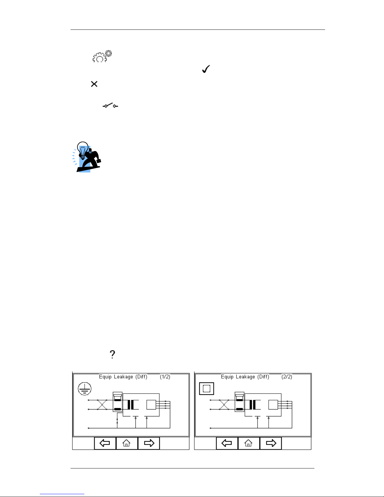
5.6. Equipment Leakage (Differential)
The Equipment Leakage Test measures the total leakage deriving from the Applied
Parts, Enclosure and Mains Parts combined to real earth.
This test is applicable to Class I and Class II B, BF and CF equipment. This is an IEC
62353 test. For a complete description of this test and applicable pass / fail limits,
please see Appendix C & D.
Press the button (F1) to obtain the schematic representation of this test:
Page 39
Rigel 288 plus Instruction Manual – Revision 1.1 - 38 -
Warning – never leave the earth bond, or any other probe attached to any
moving parts.
Warning – never touch the appliance under test whilst testing is in
progress. Doing so could result in injury due to electric shock and / or
sudden movement of any mechanical parts on the appliance.
Refer to page 8 for notes on precautions required for compliance with the
relevant safety standards.
Do not exceed the maximum permitted voltage of 30 V AC/DC
with respect to earth potential! Electric Shock danger!
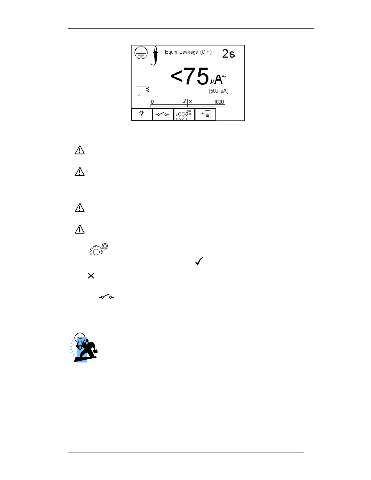
Press button (F3) to set the Test Duration, and RMS Pass/Fail limit. Use the
arrow keys to highlight and set. Press the button (F4) when complete. Pressing
the button (F3) will exit Settings mode without saving changes.
Press the button (F2) to change the mains polarity.
For both Class 1and Class II appliances, connect ALL Patient Connections or Applied
Parts to the Applied Part Module and fit the Appliance mains plug into the EUT outlet.
All Patient Connections and Applied Parts are grouped together which
eliminates the requirement to configure the Applied Part Module since
the Rigel 288 plus will short all 10 connections together as part of this
test. For this reason, the Applied Part configuration key is not
available.
For Class I equipment use the earth bond lead (from the black socket) and connect to a
conductive part of the enclosure. For measurements on conductive non-earthed parts,
the test needs to be repeated using the same probe.
For Class II devices use the earth bond lead (from the black socket) and connect to the
enclosure preferably encapsulated within conductive foil.
Page 40
Rigel 288 plus Instruction Manual – Revision 1.1 - 39 -
Press the green START key to begin the test. The test will run for the duration set or
until the red STOP key is pressed.
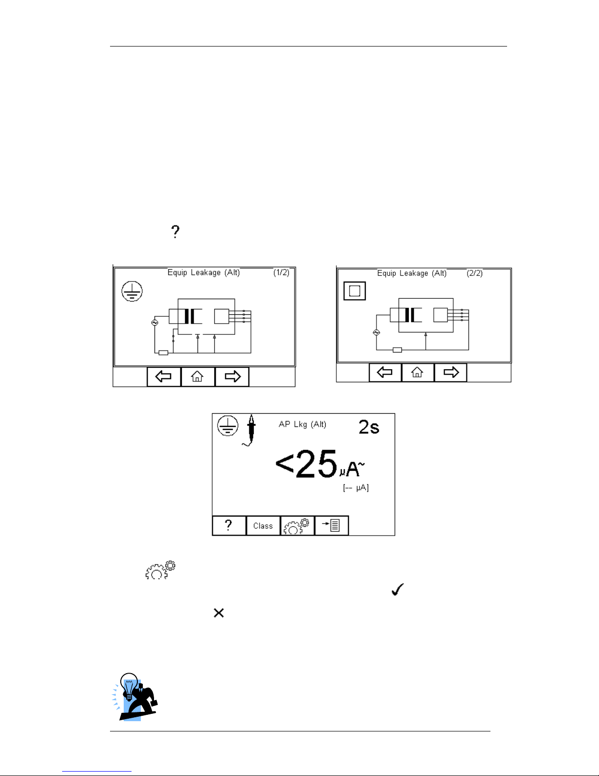
5.7. Equipment Leakage (Alternative)
This method is similar to the dielectric test between the mains parts shortened together
and the Applied Parts/accessible parts (conductive and non-conductive) connected
together.
This test is applicable to Class I and Class II B, BF and CF equipment. This is an IEC
62353 test. For a complete description of this test and applicable pass / fail limits,
please see Appendix C & D.
Press the button (F1) to obtain the schematic representation of this test:
Press button (F3) to set the Test Duration and Pass/Fail limit. Use the up,
down, left and right keys to highlight and set. Press button (F4) when
complete. Pressing button (F3) will exit Settings mode without saving changes.
For both Class 1and Class II appliances, connect ALL Patient Connections or Applied
Parts to the Applied Part Module and fit the Appliance mains plug into the EUT outlet.
All Patient Connections and Applied Parts are grouped together which
eliminates the requirement to configure the Applied Part Module as
the Rigel 288 plus will short together all 10 connections as part of this
Page 41
Rigel 288 plus Instruction Manual – Revision 1.1 - 40 -
test. For this reason, the Applied Part configuration key is not available.
For Class I equipment use the earth bond lead (from the black socket) and connect to a
conductive part of the enclosure. For measurements on conductive non-earthed parts,
the test needs to be repeated using the same probe.
For Class II devices use the earth bond lead (from the black socket) and connect to the
enclosure preferably encapsulated within conductive foil.
Press the green START key to begin the test. The test will run for the duration set or
until the red STOP key is pressed.
5.8. Applied Part Leakage (Direct)
The Applied Part Leakage Test measures the total leakage deriving from the combined
Patient Connections within an Applied Part to earth and any conductive or nonconductive parts on the enclosure (either connected or isolated from earth) under the
fault condition Mains on Applied Parts.
The Applied Part Leakage Test is applicable to class I and class II floating type (BF &
CF) Applied Parts. This is an IEC 62353 test. For a complete description of this test and
applicable pass / fail limits, please see Appendix C & D.
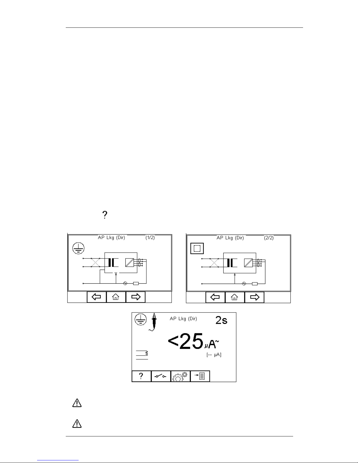
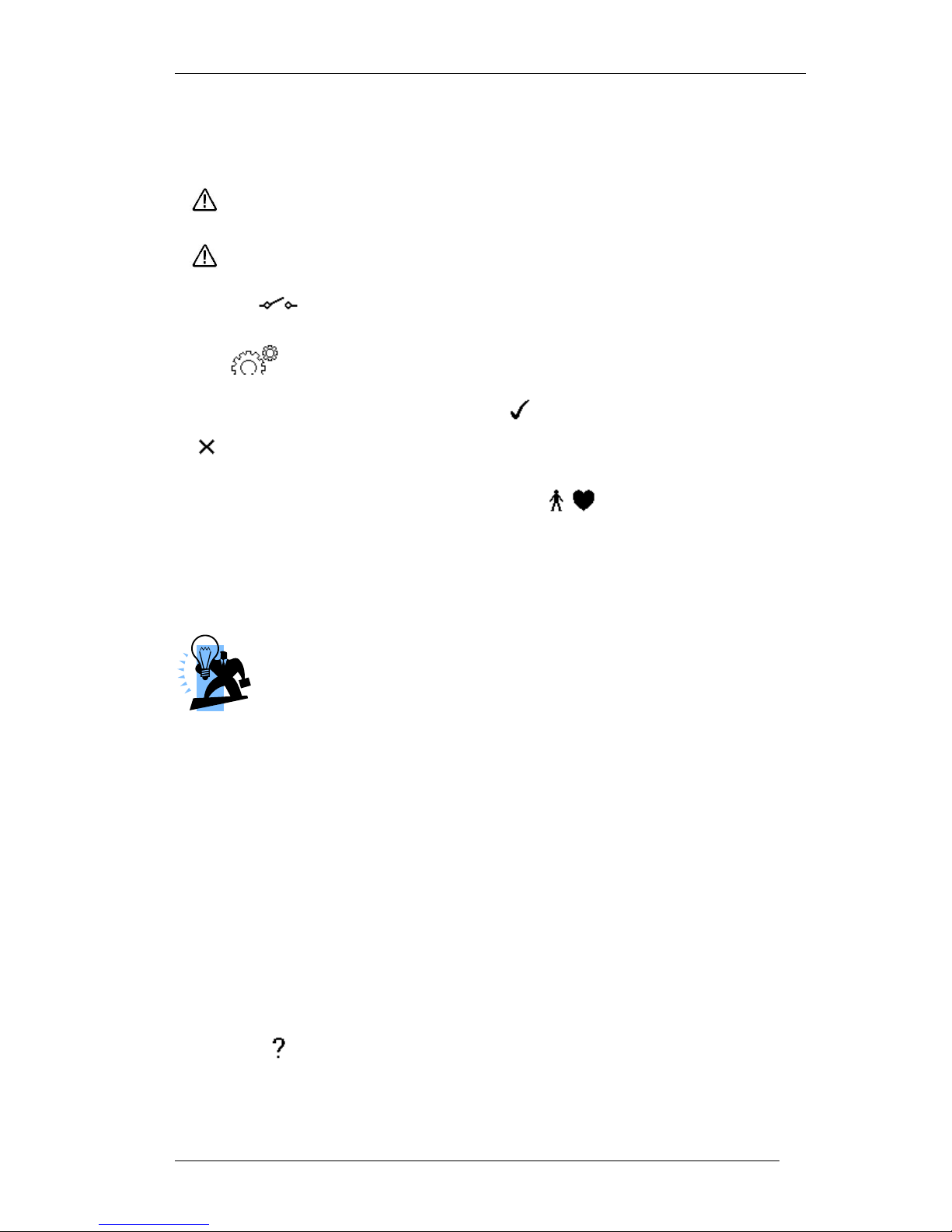
Press the button (F1) to obtain the schematic representation of this test:
Warning – never leave the earth bond, or any other probe attached to any
moving parts.
Warning – never touch the appliance under test whilst testing is in
Page 42
Rigel 288 plus Instruction Manual – Revision 1.1 - 41 -
progress. Doing so could result in injury due to electric shock and / or
sudden movement of any mechanical parts on the appliance.
Refer to page 8 for notes on precautions required for compliance with the
relevant safety standards.
Do not exceed the maximum permitted voltage of 30 V AC/DC
with respect to earth potential! Electric Shock danger!
Press the button (F2) to change the mains polarity.
Press button (F3) to set the Test Duration, Equipment Class, Applied Part
module and RMS Pass/Fail limit for BF and CF Applied Parts. Use the up, down. left
and right keys to highlight and set. Press (F4) when complete. Pressing the
button (F3) will exit Settings mode without saving changes.
To configure the Applied Part Module press the button (F1) in the Settings
menu. For instructions on using this feature, see 4.5 point 6
For both Class 1and Class II appliances, connect the Patient Connections or Applied
Parts to the Applied Part Module as per the configuration above.
For Class I equipment use the earth bond lead (from the black socket) and
connect to a conductive non-earthed part.
For Class II devices use the earth bond lead (from the black socket) and
connect to the enclosure preferably encapsulated within conductive foil.
Press the green START key to begin the test. The test will run for the duration set or
until the red STOP key is pressed.
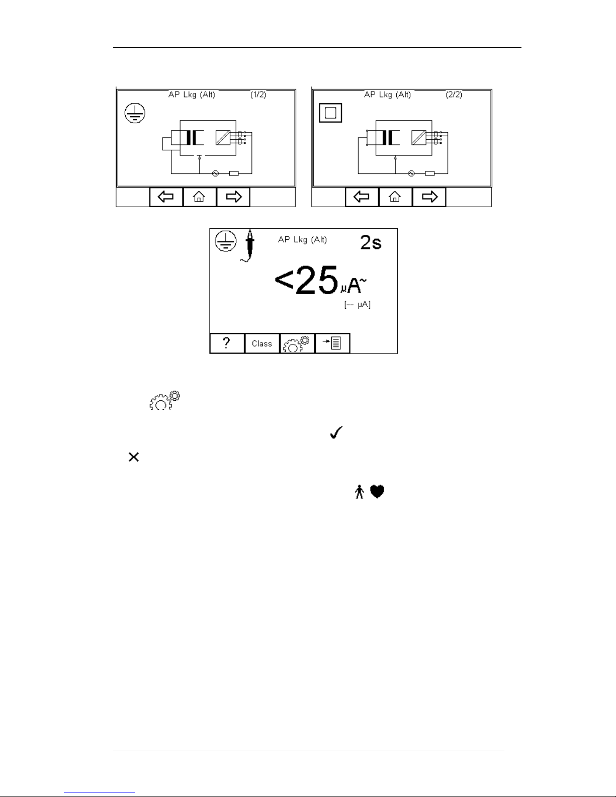
5.9. Applied Part Leakage (Alternative)
This method is similar to a dielectric test between the Applied Part and all mains
parts, EUT earth and Enclosure connected together.
The Applied Part Leakage Test is applicable to Class I and Class II floating type (BF &
CF) Applied Parts. This is an IEC 62353 test. For a complete description of this test and
applicable pass / fail limits, please see Appendix C & D.
Press the button (F1) to obtain the schematic representation of this test:
Page 43
Rigel 288 plus Instruction Manual – Revision 1.1 - 42 -
Press button (F3) to set the Test Duration, Equipment Class, Applied Part
module and RMS Pass/Fail limit for BF and CF Applied Parts. Use the up, down. left
and right keys to highlight and set. Press (F4) when complete. Pressing the
button (F3) will exit Settings mode without saving changes.
To configure the Applied Part Module press the button (F1) in the Settings
menu. For instructions on using this feature, see 4.5 point 6
For both Class 1and Class II appliances, connect the Patient Connections or Applied
Parts to the Applied Part Module as per the configuration above.
For Class I equipment use the earth bond lead (from the black socket) and connect to a
conductive non-earthed part.
For Class II devices use the earth bond lead (from the black socket) and connect to the
enclosure preferably encapsulated within conductive foil.
Press the green START key to begin the test. The test will run for the duration set or
until the red STOP key is pressed.
Page 44
Rigel 288 plus Instruction Manual – Revision 1.1 - 43 -
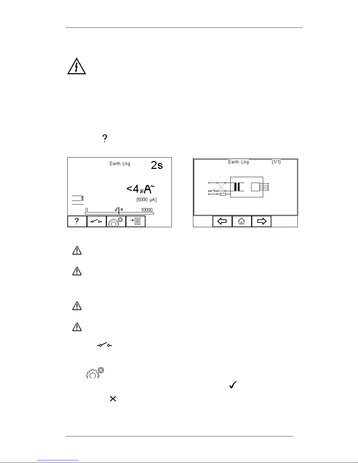
5.10. Earth Leakage Test
Mains voltage applied to EUT
The Earth Leakage Test shows the current flowing through or via the insulation of the
appliance into the protective earth conductor. The earth leakage test is important as it
demonstrates the total leakage from the EUT.
The earth leakage tests are valid for Class I equipment with Types B, BF and CF
applied parts. This is an IEC 60601-1test. For a complete description of this test and
applicable pass / fail limits, please see Appendix A & B.
Press the button (F1) to obtain the schematic representation of this test:
Warning – never leave the earth bond, or any other probe attached to any
moving parts.
Warning – never touch the appliance under test whilst testing is in
progress. Doing so could result in injury due to electric shock and / or
sudden movement of any mechanical parts on the appliance.
Refer to page 8 for notes on precautions required for compliance with the
relevant safety standards.
Do not exceed the maximum permitted voltage of 30 V AC/DC
with respect to earth potential! Electric Shock danger!
Press the button (F2) to toggle between the different single fault conditions and
mains reversal.
Press button (F3) to set the Test Duration and RMS Pass/Fail limit using the
up, down. left and right keys to highlight and set. Press (F4) when complete.
Pressing the button (F3) will exit Settings mode without saving changes.
Page 45
Rigel 288 plus Instruction Manual – Revision 1.1 - 44 -
Plug the Medical Device in the Rigel 288 plus EUT socket and press the green START
key to begin the test. The test will run for the duration set or until the red STOP key is
pressed.
5.11. Enclosure Leakage Test (mains powered)
Warning Mains voltage applied to EUT
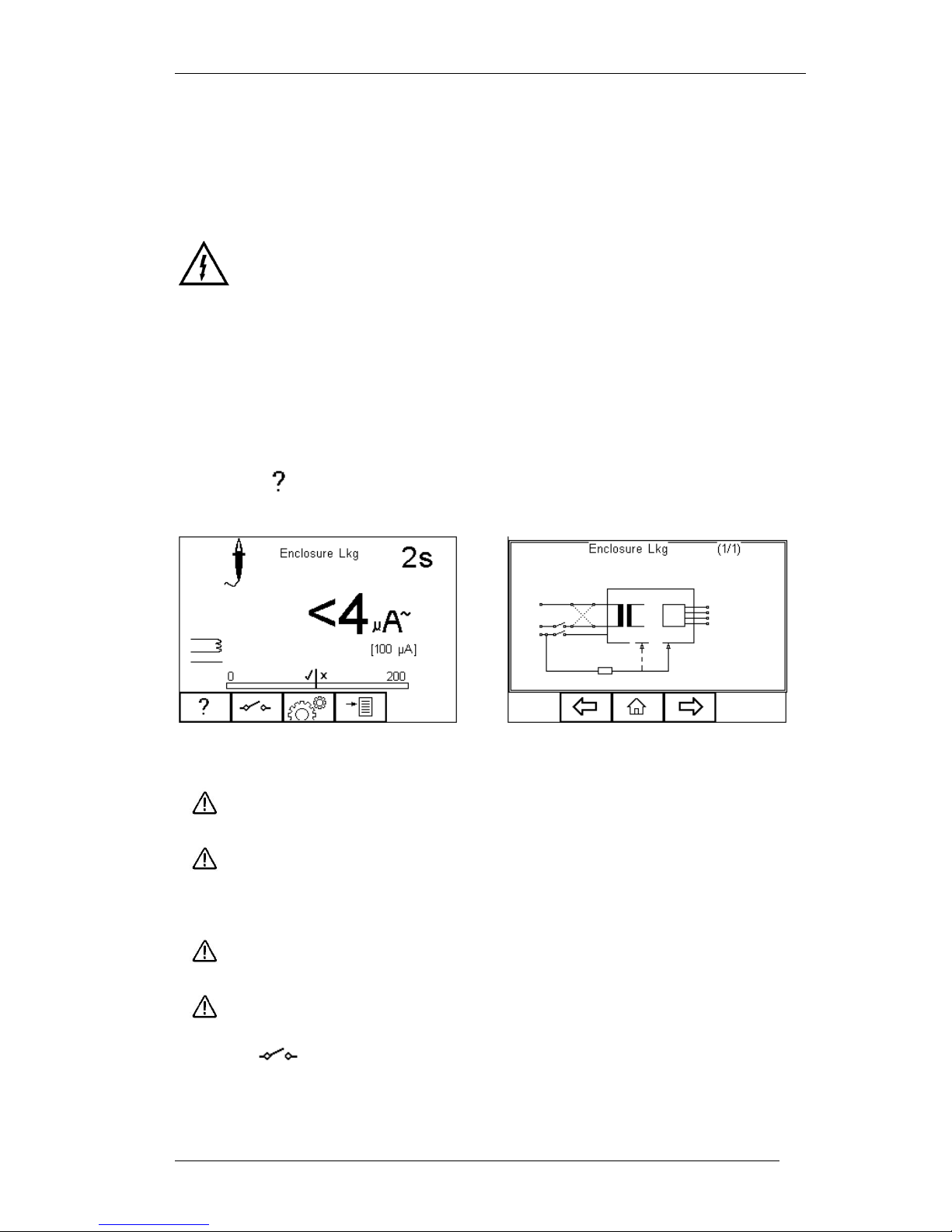
Enclosure Leakage displays the current that would flow if a person came into contact
with the housing (or any accessible part not intended for treatment or care) of the
appliance.
The Enclosure Leakage Test is valid for both Class 1 and Class II equipment with
Types B, BF and CF Applied Parts. This is an IEC 60601-1 test. For a complete
description of this test and applicable pass / fail limits, please see Appendix A & B.
Press the button (F1) to obtain the schematic representation of this test:
Warning – never leave the earth bond, or any other probe attached to any
moving parts.
Warning – never touch the appliance under test whilst testing is in
progress. Doing so could result in injury due to electric shock and / or
sudden movement of any mechanical parts on the appliance.
Refer to page 8 for notes on precautions required for compliance with the
relevant safety standards.
Do not exceed the maximum permitted voltage of 30 V AC/DC
with respect to earth potential! Electric Shock danger!
Press the button (F2) to toggle between the different single fault conditions and
mains reversal.
Page 46
Rigel 288 plus Instruction Manual – Revision 1.1 - 45 -
Press button (F3) to set the Test Duration and RMS Pass/Fail limit using the
up, down, left and right keys to highlight and set. Press (F4) when complete.
Pressing the button (F3) will exit Settings mode without saving changes.
For Class I equipment, connect the earth bond lead (from the black socket)
to a conductive part on the enclosure. Measure Enclosure Leakage on
conductive non-earthed parts separately, by repositioning the probe.
For Class II devices connect the earth bond lead (from the black socket) to the
conductive parts on the enclosure preferably encapsulated within conductive foil.
Press the START key to begin the test. The test will run for the duration set or until the
red STOP key is pressed.
5.12. Point to Point Enclosure Leakage Test (battery powered)
Warning Mains voltage applied to EUT
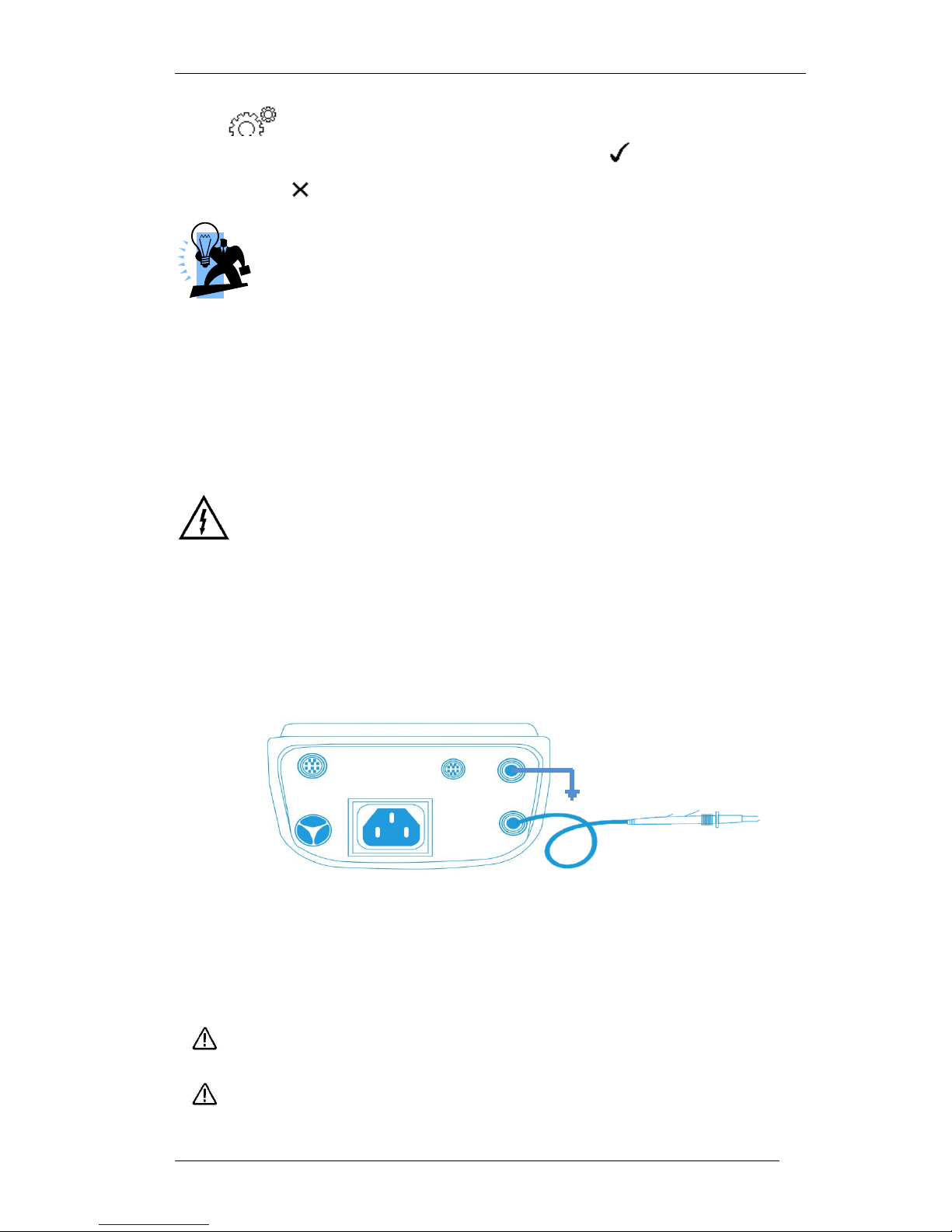
Enclosure Leakage can be done from battery power only by performing a point to point
measurement. Select Enclosure leakage and connect the Rigel 288 plus as follows:
Connect the earth reference to the GREEN (auxiliary) socket on the back panel of the
Rigel 288 plus. Connect the test probe to the BLACK socket on the back panel of the
Rigel 288 plus. See below
Press the GREEN start button, the Rigel 288 plus will inform the user of no incoming
mains, press OK to continue.
Please note that single fault conditions do not apply as these are generated in the EUT
socket which is not being used during this test.
Warning – never leave the earth bond, or any other probe attached to any
moving parts.
Warning – never touch the appliance under test whilst testing is in
progress. Doing so could result in injury due to electric shock and / or
sudden movement of any mechanical parts on the appliance.
Page 47
Rigel 288 plus Instruction Manual – Revision 1.1 - 46 -
Refer to page 8 for notes on precautions required for compliance with the
relevant safety standards.
Do not exceed the maximum permitted voltage of 30 V AC/DC
with respect to earth potential! Electric Shock danger!
Press the button (F2) to toggle between the different single fault conditions and
mains reversal.
Press button (F3) to set the Test Duration and RMS Pass/Fail limit using the
up, down, left and right keys to highlight and set. Press (F4) when complete.
Pressing the button (F3) will exit Settings mode without saving changes.
For Class I equipment, connect the earth bond lead (from the black socket)
to a conductive part on the enclosure. Measure Enclosure Leakage on
conductive non-earthed parts separately, by repositioning the probe.
For Class II devices connect the earth bond lead (from the black socket) to the
conductive parts on the enclosure preferably encapsulated within conductive foil.
Press the START key to begin the test. The test will run for the duration set or until the
red STOP key is pressed.
5.13. Patient Leakage
Warning Mains voltage applied to EUT.
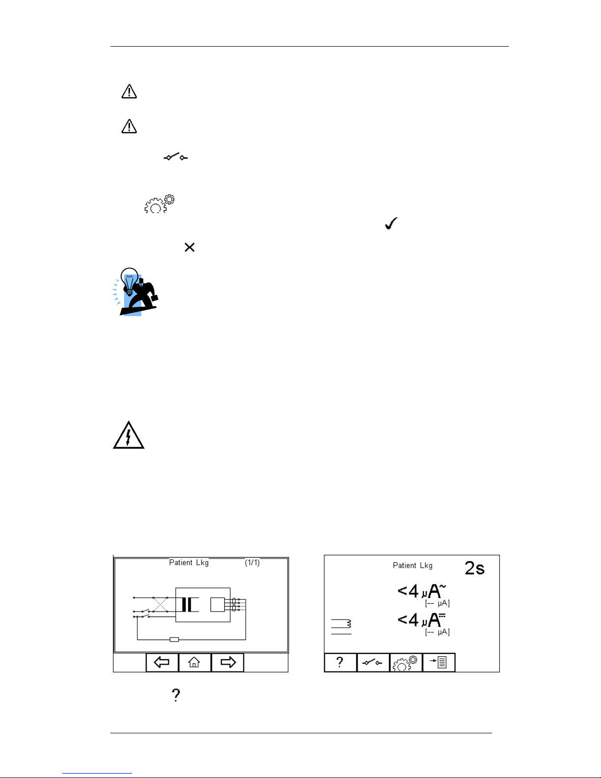
The Patient Leakage Current is the current flowing from the Applied Part via the patient
to earth or flowing from the patient via an Applied Part to earth, which originates from an
unintended voltage appearing on an external source.
The Patient Leakage Test is valid for both Class 1 and Class II equipment with Types B,
BF and CF applied. This is an IEC 60601-1 test. For a complete description of this test
and applicable pass / fail limits, please see Appendix A & B.
Press the button (F1) to obtain the schematic representation of this test:
Page 48
Rigel 288 plus Instruction Manual – Revision 1.1 - 47 -
Warning – never leave the earth bond, or any other probe attached to any
moving parts.
Warning – never touch the appliance under test whilst testing is in
progress. Doing so could result in injury due to electric shock and / or
sudden movement of any mechanical parts on the appliance.
Refer to page 8 for notes on precautions required for compliance with the
relevant safety standards.
Do not exceed the maximum permitted voltage of 30 V AC/DC
with respect to earth potential! Electric Shock danger!
Press the button (F2) to toggle between the different single fault conditions and
mains reversal.
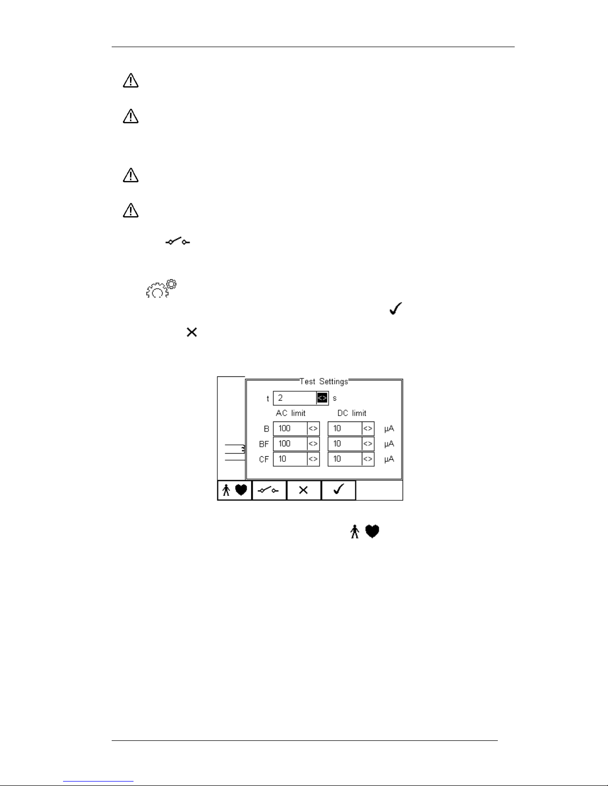
Press button (F3) to set the Test Duration and RMS Pass/Fail limit using the
up, down, left and right keys to highlight and set. Press (F4) when complete.
Pressing the button (F3) will exit Settings mode without saving changes.
To configure the Applied Part Module press the button (F1) in the Settings
menu. For instructions on using this feature, see 4.5 point 6
For both Class 1and Class II appliances, connect the Patient Connections or Applied
Parts to the Applied Part Module as per the configuration above.
Press the green START key to begin the test. The test will run for the duration set or
until the red STOP key is pressed.
Page 49
Rigel 288 plus Instruction Manual – Revision 1.1 - 48 -
5.14. Patient Leakage – F-Type
Warning Mains voltage applied to EUT.
Warning !!! This test involves applying a current limited mains potential
(110% of mains input voltage) to the Applied Parts connections. Due to
the requirements for IEC60601 this test current can be in excess of 5mA
under short circuit conditions and as such is hazardous to the user.
Caution should be taken when conducting this test. Current limiting is
via a limiting resistor in series with the measurement circuit.
The Patient Leakage F-Type Test (also known as mains on Applied Parts test) displays
the current that would flow if a mains potential was applied to the Applied Part which
was attached to a patient (i.e. a single fault condition).
The F-type Leakage test is valid for both Class 1 and Class II equipment with BF and /
or CF applied parts and are measured under mains normal or reverse and source
voltage normal or reverse conditions. This is an IEC 60601-1 test. For a complete
description of this test and applicable pass / fail limits, please see Appendix A & B.
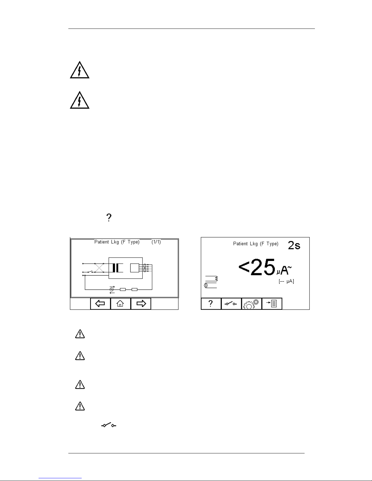
Press the button (F1) to obtain the schematic representation of this test:
Warning – never leave the earth bond, or any other probe attached to any
moving parts.
Warning – never touch the appliance under test whilst testing is in
progress. Doing so could result in injury due to electric shock and / or
sudden movement of any mechanical parts on the appliance.
Refer to page 8 for notes on precautions required for compliance with the
relevant safety standards.
Do not exceed the maximum permitted voltage of 30 V AC/DC
with respect to earth potential! Electric Shock danger!
Press the button (F2) to toggle between the different single fault conditions and
mains reversal.
Page 50
Rigel 288 plus Instruction Manual – Revision 1.1 - 49 -
Press button (F3) to set the Test Duration and RMS Pass/Fail limit using the
up, down, left and right keys to highlight and set. Press (F4) when complete.
Pressing the button (F3) will exit Settings mode without saving changes.
To configure the Applied Part Module press the button (F1) in the Settings
menu. For instructions on using this feature, see 4.5 point 6
For both Class 1and Class II appliances, connect the Patient Connections or Applied
Parts to the Applied Part Module as per the configuration above.
Press the green START key to begin the test. The test will run for the duration set or
until the red STOP key is pressed.
5.15. Patient Auxiliary Current
Warning Mains voltage applied to EUT.
The Patient Auxiliary Current displays the leakage current that would flow between
Applied Parts under normal and fault conditions. For these tests, current is measured
between a single part of the applied part and all other applied parts connected together.
The Patient Auxiliary Leakage test is valid for both Class 1 and Class II equipment with
Types B, BF and CF applied parts. This is an IEC 60601-1 test. For a complete
description of this test and applicable pass / fail limits, please see Appendix A & B.
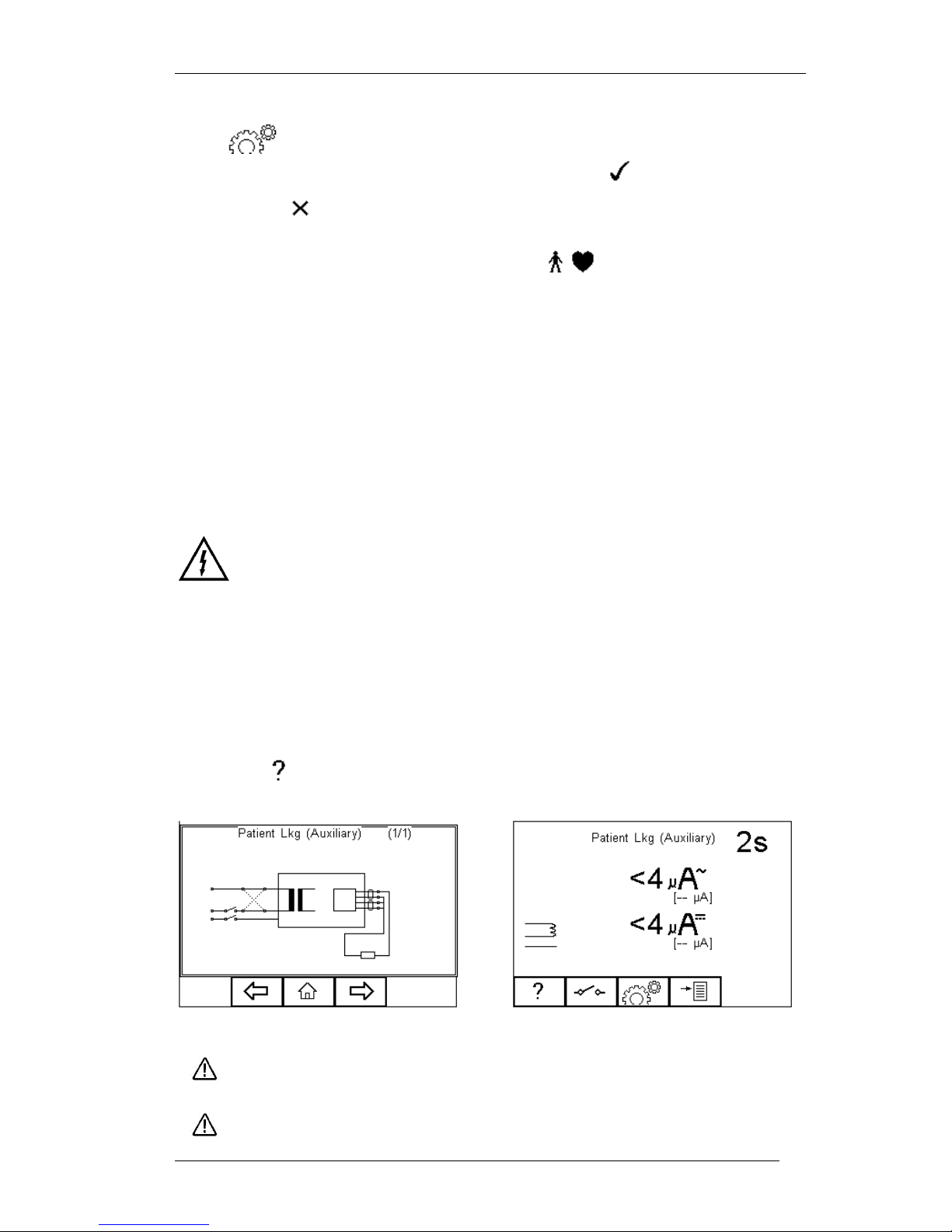
Press the button (F1) to obtain the schematic representation of this test:
Warning – never leave the earth bond, or any other probe attached to any
moving parts.
Warning – never touch the appliance under test whilst testing is in
Page 51
Rigel 288 plus Instruction Manual – Revision 1.1 - 50 -
progress. Doing so could result in injury due to electric shock and / or
sudden movement of any mechanical parts on the appliance.
Refer to page 8 for notes on precautions required for compliance with the
relevant safety standards.
Do not exceed the maximum permitted voltage of 30 V AC/DC
with respect to earth potential! Electric Shock danger!
Press the button (F2) to toggle between the different single fault conditions and
mains reversal.
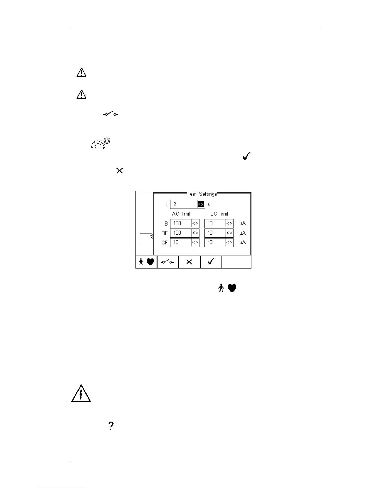
Press button (F3) to set the Test Duration and RMS Pass/Fail limit using the
up, down, left and right keys to highlight and set. Press (F4) when complete.
Pressing the button (F3) will exit Settings mode without saving changes.
To configure the Applied Part Module press the button (F1) in the Settings
menu. For instructions on using this feature, see 4.5 point 6
For both Class 1and Class II appliances, connect the Patient Connections or Applied
Parts to the Applied Part Module as per the configuration above.
Press the green START key to begin the test. The test will run for the duration set or
until the red STOP key is pressed.
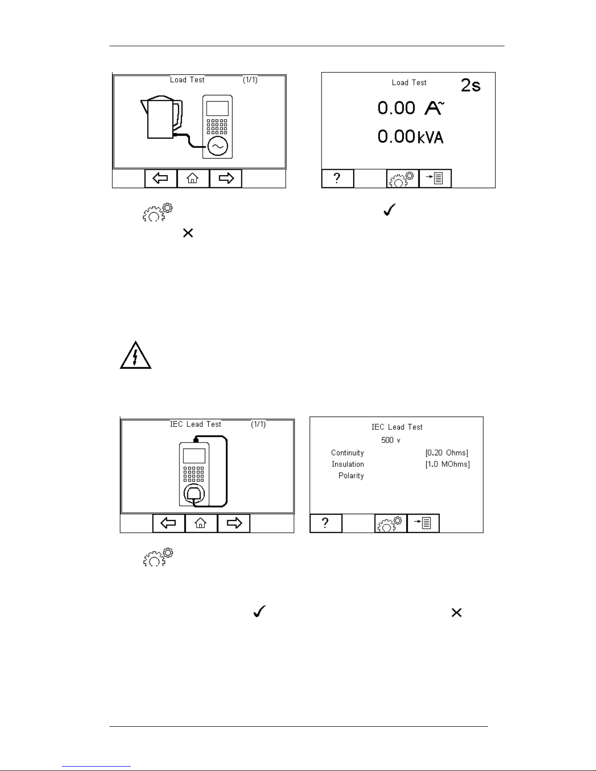
5.16. Load Test
Warning Mains voltage applied to EUT.
This test provides a means of testing the Load current (in Amps) and power in KVA.
Press the button (F1) to obtain the schematic representation of this test:
Page 52
Rigel 288 plus Instruction Manual – Revision 1.1 - 51 -
Press button (F3) to set the Test Duration. Press (F4) when complete.
Pressing the button (F3) will exit Settings mode without saving changes.
Press the green START key to begin the test. The test will run for the duration set or
until the red STOP key is pressed.
5.17. IEC Lead
Warning Mains voltage applied to IEC Lead.
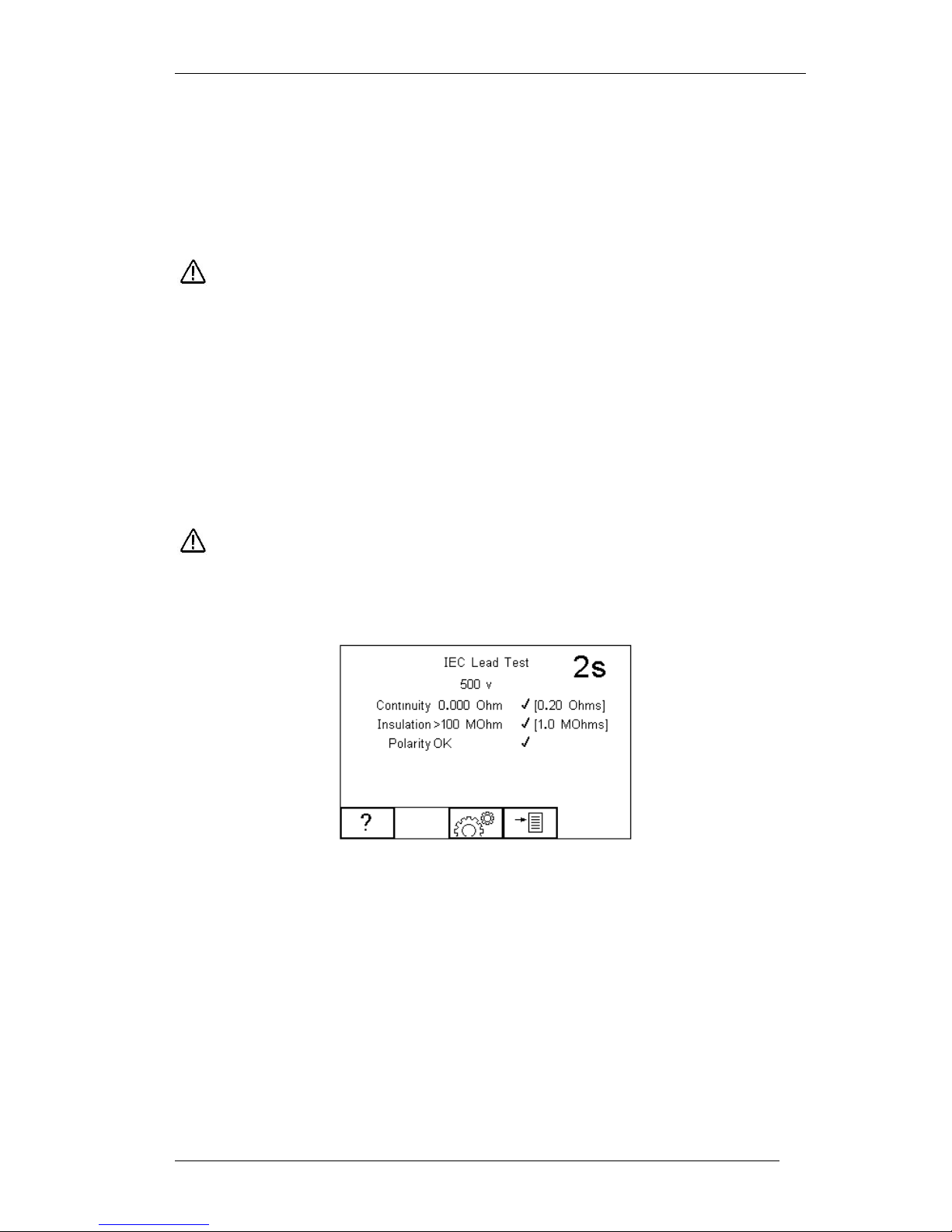
This test provides means of testing the continuity, insulation and polarity* of IEC test
leads.
Press button (F3) to set the Pass/Fail limits for Continuity, Insulation and Test
Voltage. Use the up, down, left and right keys to highlight and set. The pass/fail limit for
the continuity stage can be calculated using the Calc button (F2). Enter the type and
length of cable and a new limit will be calculated. This can be overridden by selecting
the limit from the list. Press (F4) when complete. Pressing the button
(F3) will exit Settings mode without saving changes.
To perform an IEC lead test, connect the IEC socket side of the lead into the IEC inlet
plug of the Rigel 288 plus. Connect the mains plug side of the lead into the EUT socket,
of the Rigel 288 plus.
Page 53
Rigel 288 plus Instruction Manual – Revision 1.1 - 52 -
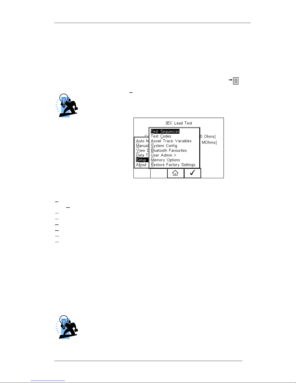
To start the IEC lead test, press the green START key.
The earth continuity resistance for the lead is measured using a ±200mA test current.
The display indicates the highest resistance and the pass/fail status. If this resistance is
less than the pass/fail limit, then the insulation resistance will be measured.
During an insulation resistance measurement, a high voltage is
applied between Live/Neutral and Earth of the IEC lead.
The insulation resistance of the lead is measured over a period of 2 seconds. The
display shows the final reading and the pass/fail status. If the insulation resistance is
greater than the pass/fail limit, then the lead polarity will be checked.
The lead polarity stage checks for short and open circuit conditions on the live and
neutral conductors. It also checks that the live and neutral wires are not crossed. When
testing non-polarised IEC leads (e.g. Schuko mains leads) Live and Neutral can be
crossed without implications. As such, this feature can be excluded. See section 3.4.6.
The polarity test is performed at mains voltage.
The display shows the final result and the pass/fail status. See below.
Page 54
Rigel 288 plus Instruction Manual – Revision 1.1 - 53 -
6. Customising your tester
The Rigel 288 plus is designed to allow the user to customise the device to allow default
setting in order to speed up the testing such as, default lists of manufacturers, model
numbers, user test protocols, automatic printing following test, fault menu’s and so on.
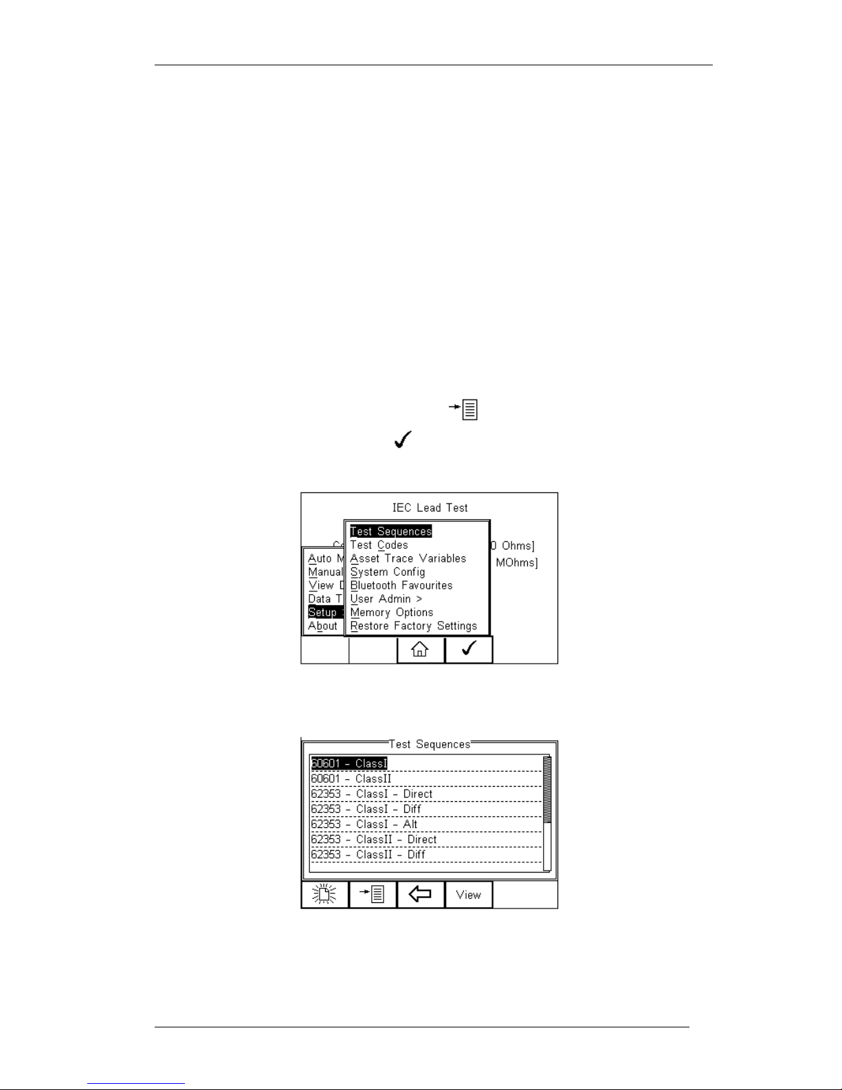
All custom facilities can be found under the SETUP menu. Simply press the [F4]
from the home screen and select Setup from the menu.
The underlined character acts as a short key to allow swift navigation
through the menu structure.
Available options
Test Sequences Modify or create test sequences (see 6.1)
Test Codes Generate 4-digit test routine short cuts (see 6.2)
Asset Trace Variables Generate default list of variables (see 6.3)
Systems Config Configure default test options (see 6.4)
Blue Tooth Favourites Setup your Blue Tooth devices (see 6.5)
User admin Setup users and preferences (see 6.6)
Memory Options Manage the tester’s memory (see 6.7)
Restore Factory Settings Defaults the tester to factory settings (see 6.8)
6.1. Test Sequences
The Rigel 288 plus can be set-up to create new test sequences to meet local
requirements or to modify existing test sequences to meet personal preference.
The preset Test Sequences are according to the applicable medical standard. Preset
test sequences cannot be changed by the user, however alterations are possible by
producing a copy of the default test sequence setting.
The total number of possible preset test sequences is 50 including 12
default test sequences. Each sequence can be linked to a specific
configuration of Applied Parts by designating a unique 4 digit Test Code
(see 4.2) which can be entered prior to each test as a short cut / menu
bypass function.
Page 55
Rigel 288 plus Instruction Manual – Revision 1.1 - 54 -
6.1.1. User definable tests
This feature gives the Rigel 288 plus the capability of recording user defined visual
inspections, checks or tests including measurements from SPO2, ECG, NIBP, Defib,
Infusion, Ventilation, Pressure etc.
The input is text only as no measurements are performed by the Rigel 288 plus during
these tests. The user can enter questions or instructions followed by either a
PASS/FAIL result or alpha numeric input. Preset engineering units e.g. %, Joules,
mmHg, PSI, CmH2O etc are available.
6.1.2. View, Delete or Copy an existing Test Routine.
Preset test sequences cannot be deleted or changed by the user however, alterations
are possible by producing a copy of the default test sequence.
To enter the Test Sequences menu, click on , followed by Setup. Select the Test
Sequences from the list and press (F4).
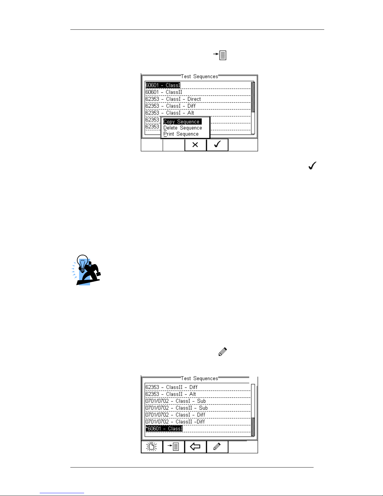
The following overview is provided and shows the list of default and customised test
sequences availble. Copied Test Sequences will appear in the list with an *pre-fix.
From this menu, the user is able to View a test sequence by pressing the View button
(F4). Default test settings cannot be altered at any stage.
Page 56
Rigel 288 plus Instruction Manual – Revision 1.1 - 55 -
To Copy, Delete or Print an existing or default test sequence, use the Up & Down arrow
keys to highlight the test sequence and press the button (F2).
Use the Up & Down Arrow keys to select the required action and press the
(F4) to confirm. Press Escape (F3) to cancel and return to previous screen.
Copied Test Sequences will appear in the list with an *pre-fix. All Copied test
Sequences can be edited. See 6.1.3 for more on editing test sequences.
Print Test Sequence will provide an overview of the Test Sequence on the Favourite
Blue Tooth Printer. See 6.5 for help on setting up Blue Tooth devices.
Delete Sequence will remove the highlighted test sequence from the memory of the
Rigel 288 plus.
Default Test Sequences cannot be Deleted.
6.1.3. Modifying (Edit) Existing Test Sequences
Preset test sequences cannot be modified by the user, however alterations are possible
by producing a copy of the default test setting (see 6.1.2).
Non-default Test Sequences can be modified from the Test Sequences menu. When
non-default Test Sequences are highlighted, the (F4) will appear in the menu
screen.
Page 57
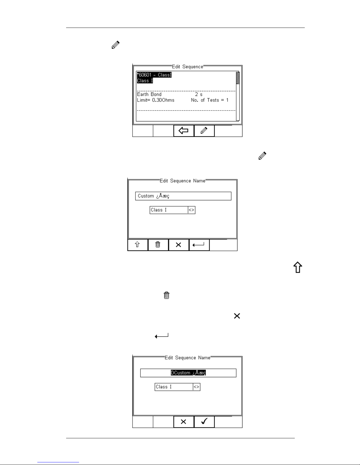
Rigel 288 plus Instruction Manual – Revision 1.1 - 56 -
Pressing the button (F4) will open the Test Sequence for Editing as shown
below;
To change the Name and or Class of the Test Sequence, press the Button (F4)
and enter the Name and or Class required.
To change to upper or lower case or use language specific characters, press the
button (F1) and select the required entry.
To Delete a character, press the button (F2)
To return to the previous menu without changes, press the button (F3)
To confirm the entry, press the button (F4)
Page 58
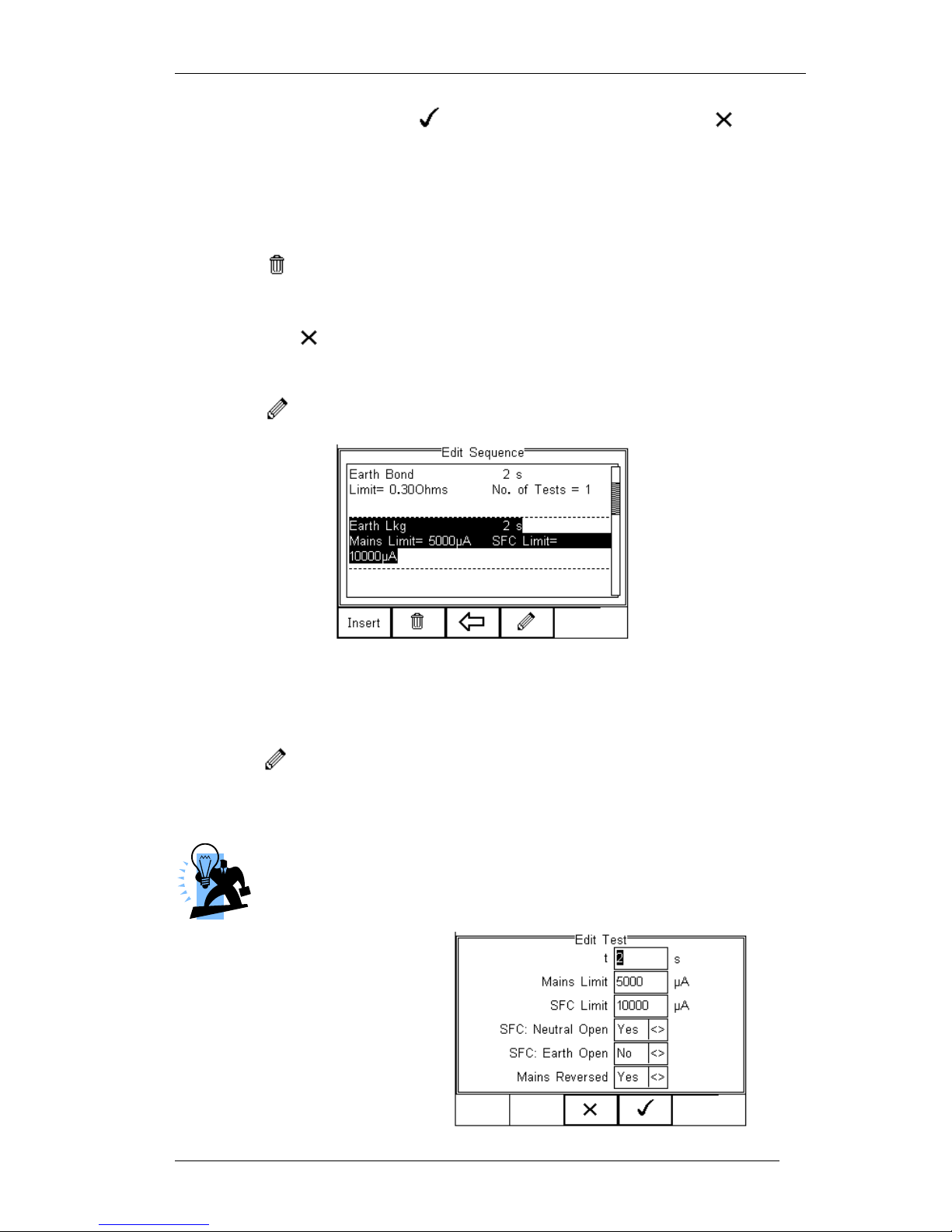
Rigel 288 plus Instruction Manual – Revision 1.1 - 57 -
Confirm the changes with the button (F3) or cancel using the button
(F4).
To Insert a new test, highlight the test using the Up & Down arrow keys and press the
Insert button (F1)
To Delete an individual test, highlight the test using the Up & Down arrow keys and
press the button (F2)
To go back to the previous menu, highlight the test using the Up & Down arrow keys
and press the button (F3)
To modify an individual test, highlight the test using the Up & Down arrow keys and
press the Button (F4)
6.1.4. Edit individual Test
Press the button (F4) as shown above. The sub menu will allow you to alter the
settings for; Test duration, Mains Limit, Single Fault Limit, Neutral Open*, Earth Open*,
Mains Reversal*.
Default test sequences have the appropiate Single Fault Conditions set to
meet the Standard Requirements. For specifc use, Single Fault Conditions
could be de-activated by selecting the drop down box using the up and
down keys and highlight the drop down box. Change the content using the
left and right keys.
Page 59
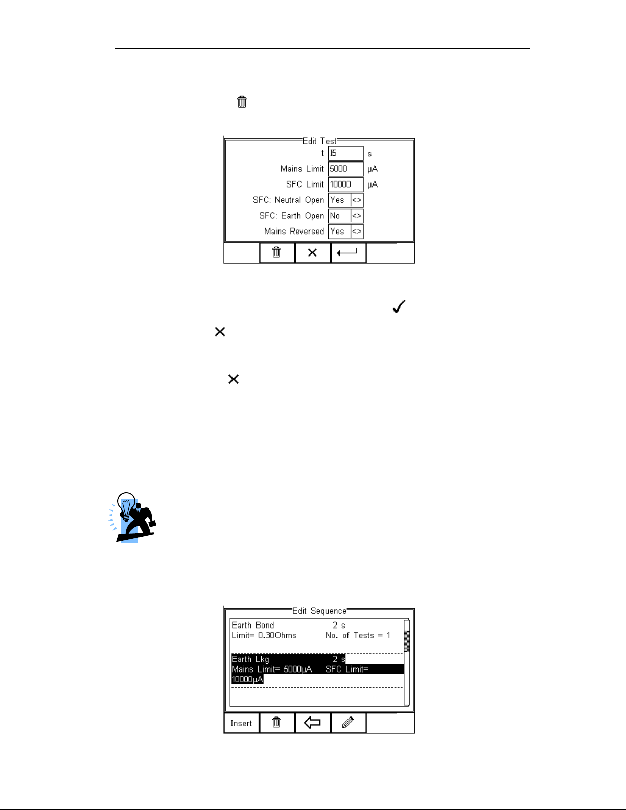
Rigel 288 plus Instruction Manual – Revision 1.1 - 58 -
Highlight the required field using the up and down keys. To change the content either
use the left and right keys or use the keypad to enter the correct data. To Delete the
field content, press the button as shown below.
When the right settings have been achieved, press the button (F4) to save the
changes or press (F3) to return to the previous menu without changes.
Repeat this action for every test that requires editing. Once all the requires tests are
programmed, press (F3) to exit.
6.1.5. Insert an individual safety test
To insert an individual safety test we use the up and down keys to highlight the position
where a new test needs inserting and press the Insert button (F1) from the menu below.
Tests will be inserted before the highlighted position not after.
To modify a test sequence, please refer to 6.1.3.
Page 60
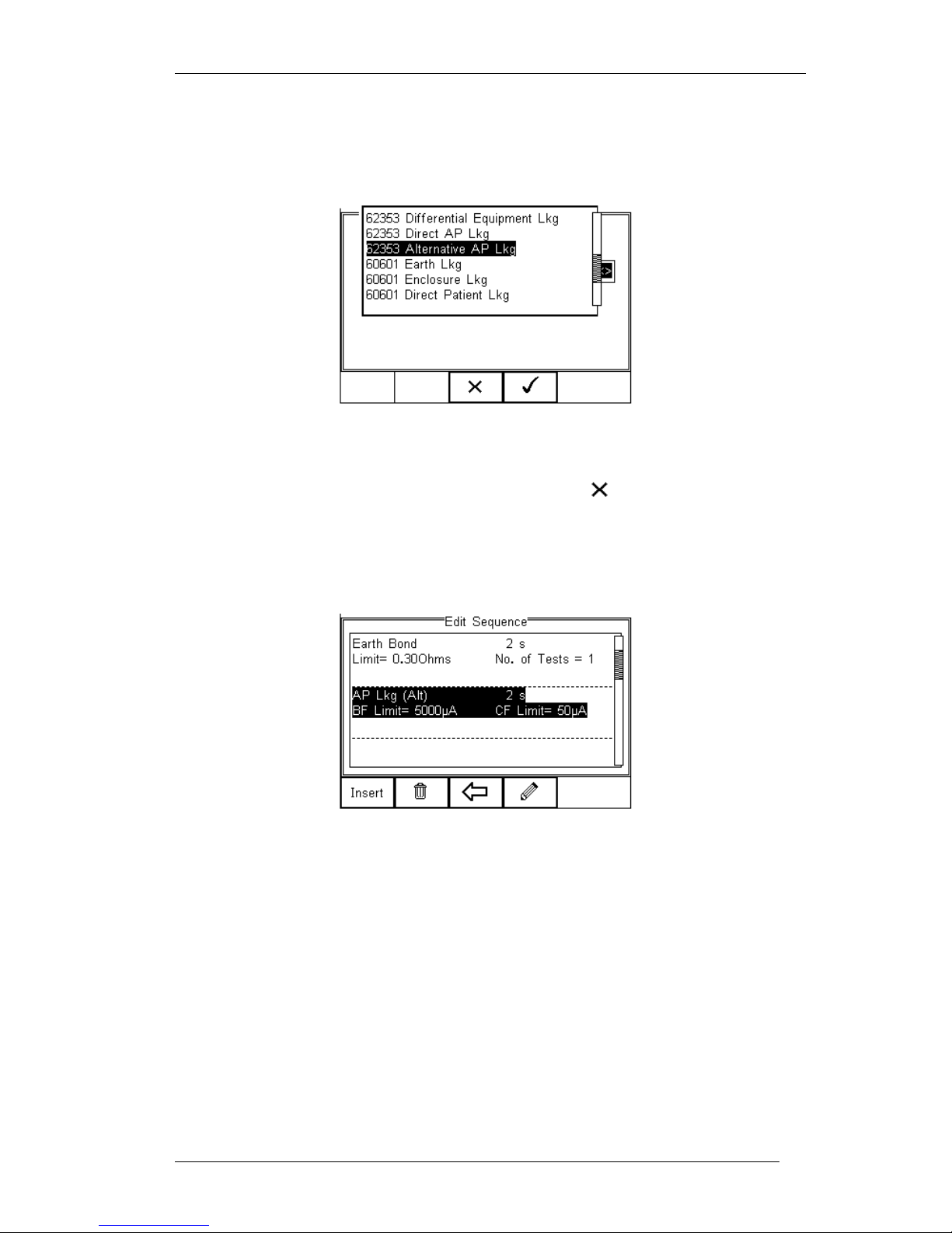
Rigel 288 plus Instruction Manual – Revision 1.1 - 59 -
Once the Insert button (F1) has been pressed, a drop down box will appear with all
available safety and inspection tests. Activate the drop down box using the left key and
or scroll through the available tests using the up and down keys.
Once the desired test has been highlighted, confirm using the OK button (F4) and finally
confirm to insert into the test Sequence. Pressing the button (F3) will return to
the previous screen without changes being made.
The individual test has now been inserted and can be edited as described in 6.1.2
Further electrical safety tests can be inserted or deleted by following the steps
described herein.
Proceed with non-electrical safety tests as described in the following or save the new
Test Sequence by following the steps below.
6.1.6. Insert a non-electrical safety test
Non-electrical safety tests are intended to allow the user to capture additional
information either prior to or after a safety test is completed. Such information could
indicate the performance of the Medical Device (eg NIBP reading, Defibrillator Energy,
Flow rate on Infusion device, SPO2 reading etc).
Page 61
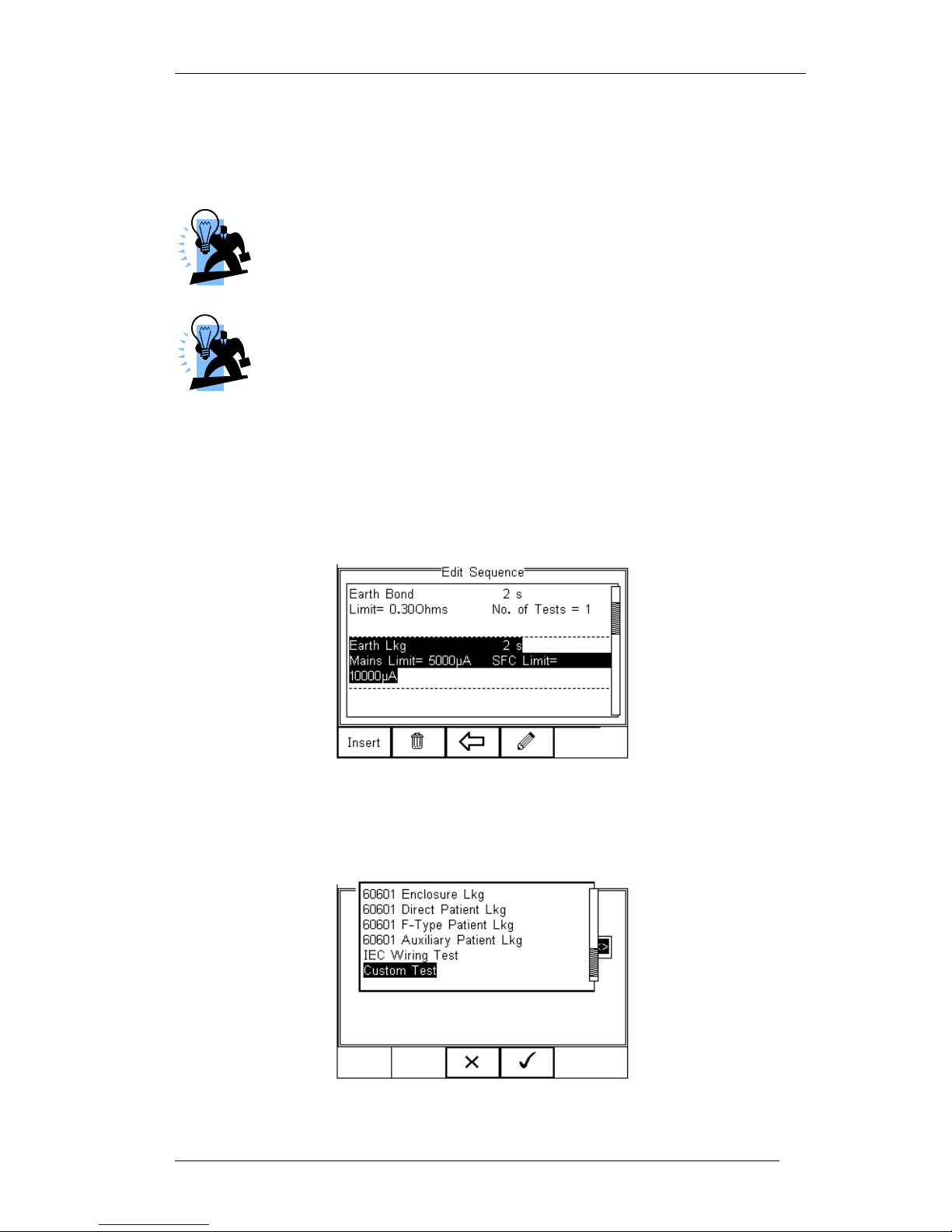
Rigel 288 plus Instruction Manual – Revision 1.1 - 60 -
This feature can also be used to instruct the user to inspect certain criteria (eg. Labels,
software version, certain damage or upgrades) prior to a safety test as part of the Visual
Inspection. To create customised visual inspections, use the insert Custom Test
function using the instructions below and set the engineering units to blank.
Create a unique range of visual tests or instructions by creating a new
test sequence (see 6.1.6) and select Custom Test as the nature of the
test. This will create a unique test sequence which can be linked to
other Test Sequences or Applied Part Configurations using Test
Codes. See 6.2 for more information. This allows the user to insert
default customised visual checks or perfomance tests (eg when
testing NIBP monitors, Defibrillators etc)
The maximum number of characters in the test description or instruction is
255.
To insert a non-electrical safety test, highlight the place where a new test needs
inserting using the up and down keys and press the Insert button (F1) from the menu
below.
Note; Tests will be inserted before the highlighted position not after.
Once the Insert button (F1) has been pressed, a drop down box will appear with all
available safety tests and inspection available. Activate the drop down box using the left
key and select the Custom Test option.
Page 62

Rigel 288 plus Instruction Manual – Revision 1.1 - 61 -
Confirm using the button (F4). The following menu will define the nature of the
non-electrical safety test (eg Equipment performance check at the end of a safety test).
Use the drop down box to choose a preset instruction and engineering unit or simply
type in the boxes provided. Newly entered data will be added to the drop down box on a
first come first serve basis.
To insert the new Custom Test, press the button (F4) or exit using the
button (F3) and return to the previous screen without changes being made.
Further tests can be inserted or deleted by following the steps described herein.
Save the changes for future use by pressing the key followed by the button.
If the Escape button (F3) is pressed, the Rigel 288 plus will return to the previous meny
without changes being made.
Page 63
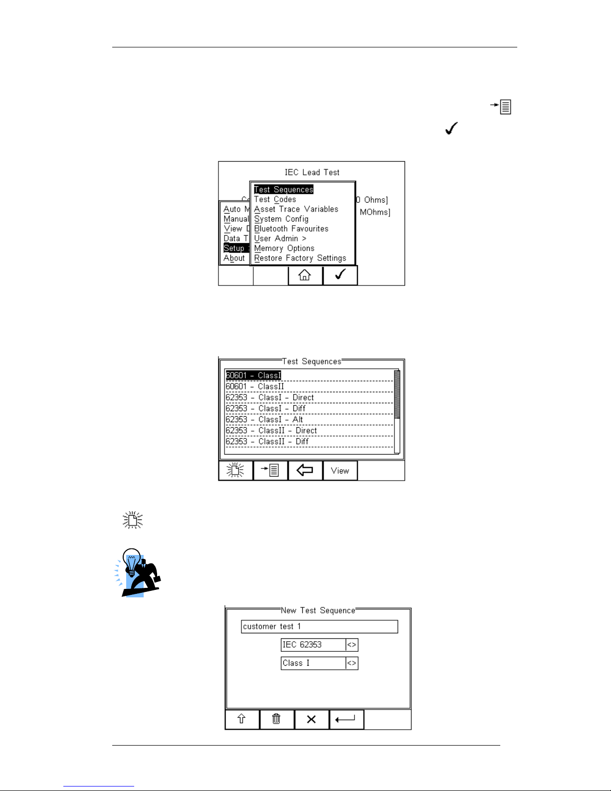
Rigel 288 plus Instruction Manual – Revision 1.1 - 62 -
6.1.7. Create a new Test Sequence
To create a new Test Sequence, enter the Test Sequences menu by clicking on ,
followed by Setup. Select the Test Sequences from the list and press (F4).
The following screen displays the list of default and customised tests available. Copied
Test Sequences will appear in the list with an *pre-fix.
From this menu, the user is able to create a new Test Sequence by pressing the
button (F1) .
When choosing any of the standards other than –NONE-, all applicable
individual tests will be activated and are available for modification. To
modify a Test Sequence, please refer to 6.1.3. (test standards are not part
of this screen in firmware versions 2.11 and higher)
Page 64
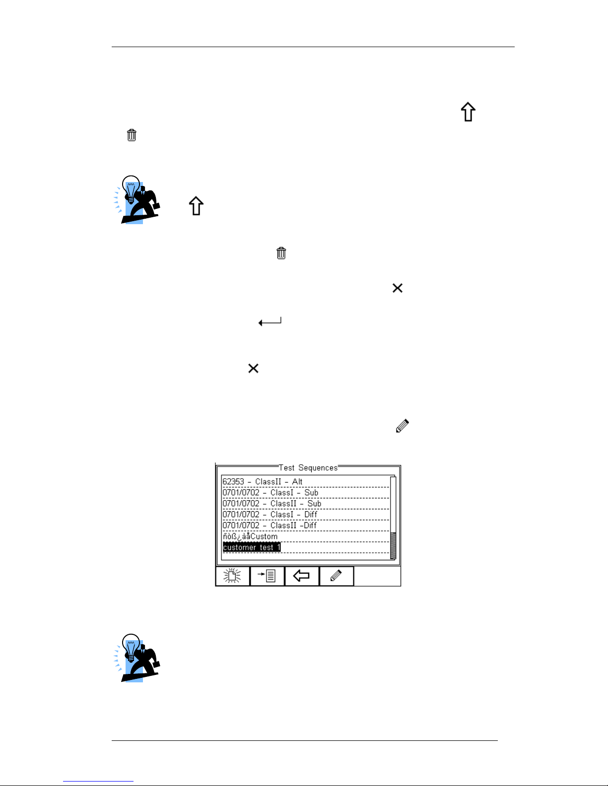
Rigel 288 plus Instruction Manual – Revision 1.1 - 63 -
When chosing Test –None-, the Test Sequence will only be set to an Inspection. Refer
to 6.1.6 for further details.
When the text box is activated and text is entered, function keys F1 and F2
appear automatically. In this instance ‘customer test 1’ has been created as
Test Name, with Class 1 and to Test Standard IEC 62353.
To change to upper or lower case or use language specific charaters, press
the button (F1) and select the required entry.
To Delete a character, press the button (F2)
To return to the previous menu without changes, press the button (F3)
To confirm the entry, press the button (F4)
Next step is to save the name of the newly create Test Name, by pressing the OK
button (F4). Pressing the key (F3) would return to the Test Sequence menu
without changes.
The newly created Test Name now appears in the Test Sequence menu and can be
modified to include the required individual tests. Press the button (F4) to open
the sequence for editing.
Once the Test Sequence has been opened, individual tests can be inserted by
highlighting the place where a new test needs inserting using the up and down keys.
Note; Tests will be inserted before the highlighted position not after.
To modify a test sequence, please refer to 6.1.3
Page 65
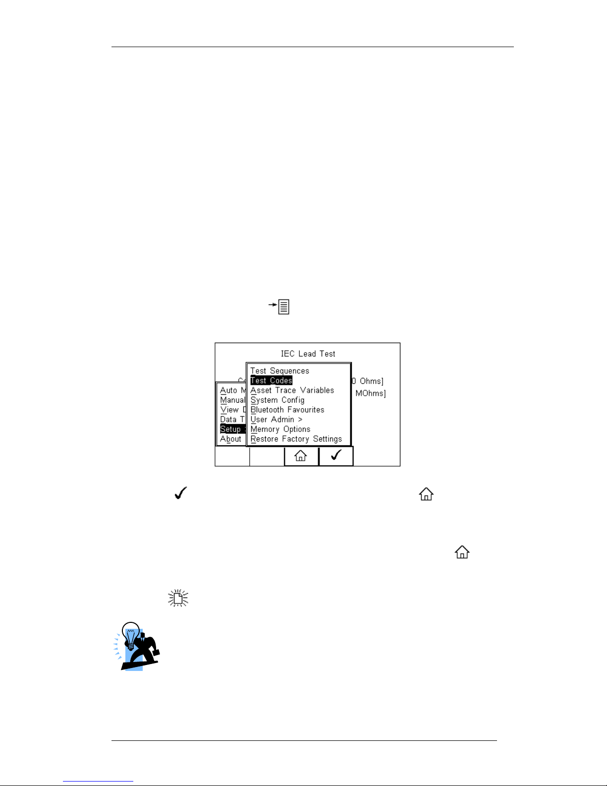
Rigel 288 plus Instruction Manual – Revision 1.1 - 64 -
6.2. Test Codes
Test codes can be used to create a 4-digit ‘short cut’ code in order to group custom and
or pre-set test(s), Applied Part configurations and test setup in either Automatic or Semi
Automatic mode. See section 4.5.1 for Automatic vs Semi Automatic testing.
For example, a specific brand or make of patient monitor is PC based, has a start-up
time of 1 minute and requires a specific Visual Inspection followed by a Semi Automatic
Electrical Safety Test and Functional Test sequence. In addition the patient monitor has
a specific configuration of Applied Parts. All this information can be grouped under a 4digit Test Code and will speed up the tester setup significantly. Once the 4-digit code is
entered in the (Semi) Automatic Test, the Rigel 288 plus is preset with all test settings
applicable to the device under test.
6.2.1. Create New Test Codes
To create a Test Code, press the button (F4) from the home screen, select Setup
from the menu and select Test Codes from the list as shown below.
Press the button (F4) to select Test Codes. Press the button (F3) to
return to the Home screen.
The following screen displays the initial menu in which New Test Codes can be created
(F1), existing Test Codes can be Edited (F4) or Deleted (F2). Press the button
(F3) to go back to the Home screen.
Press the button (F1). This will provide you with the first Test Code, TC01.
Test Codes require a 4-digit number and as such, the name MUST be
changed to a 4-digit number before it can be used.
Page 66
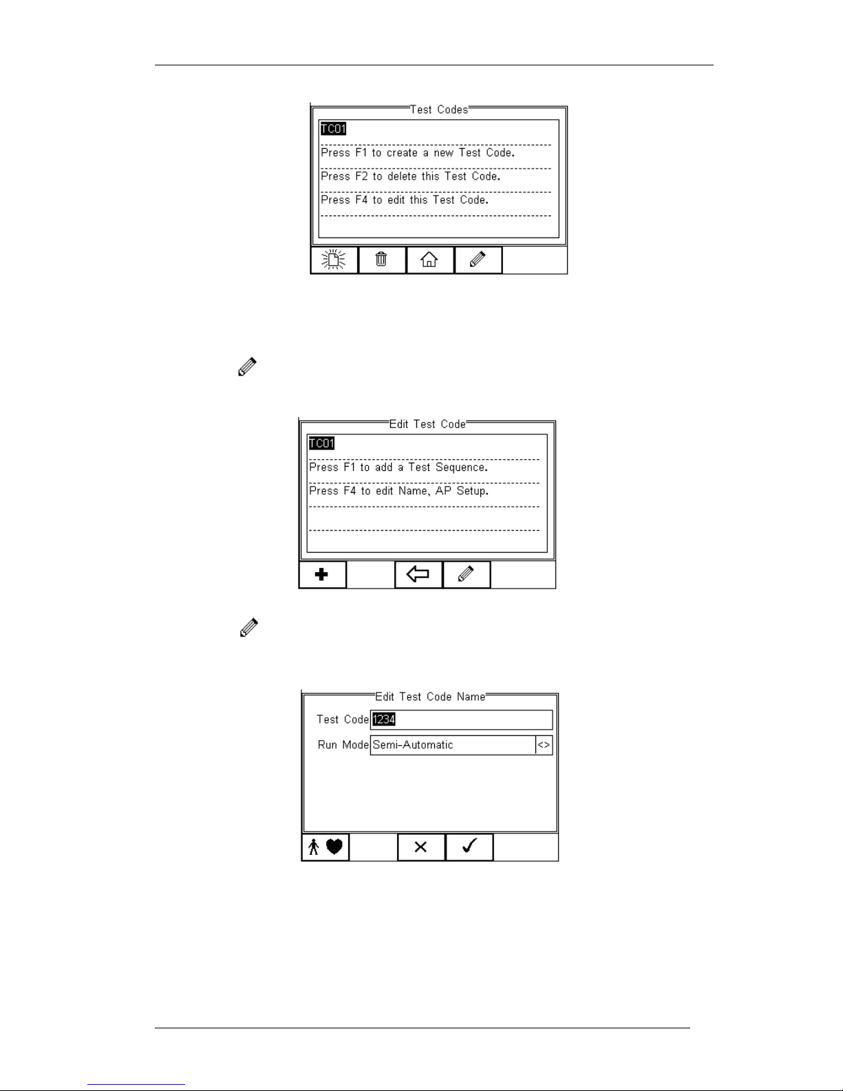
Rigel 288 plus Instruction Manual – Revision 1.1 - 65 -
The first Test Code has now been made available but requires a unique 4-digit code,
followed by a number of functions / configurations to be grouped.
Press the button (F4) to configure the Test Code.
Press the button (F4) to allocate a unique 4-digit code and or to configure the
Applied Part setup and test mode to Semi or Full Automatic.
Enter a 4-digit Test Code, in this example 1234, and use up. Down. Left and right keys
to select either Semi Automatic or Automatic. (see 4.5.1)
Page 67
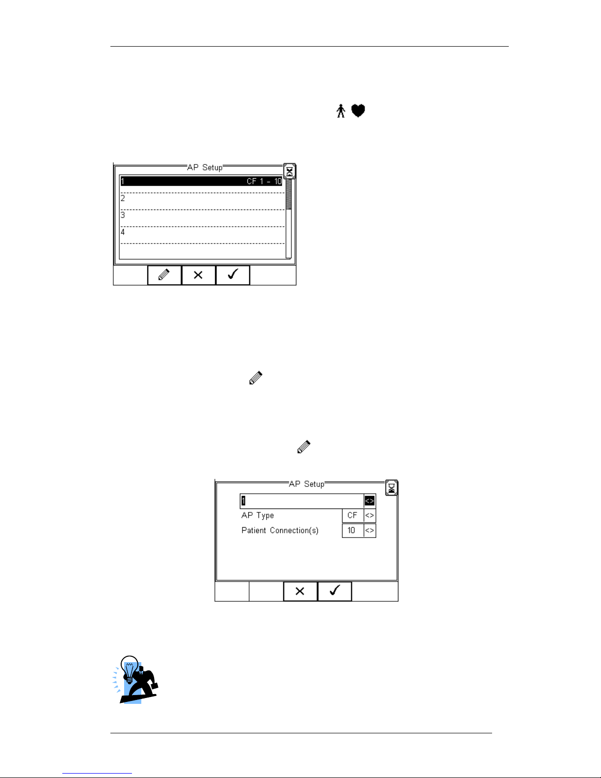
Rigel 288 plus Instruction Manual – Revision 1.1 - 66 -
6.2.2. Configuring the Applied Part Module
To configure the Applied Part settings, press the button (F1)
The following screen presents a default setup for:
10 x type CF (1..10)
The numbers on the left 1…10 define the Applied Part number, the numbers in each
line (eg 1-3) define the number of Patient Connections within that Applied Part.
Each Applied Part can also be given a name to increase the traceability.
To change the default settings, highlight the Applied Part that requires modification or
configuration and press the button (F2).
In this example we change Applied Part 1 to be a 5-lead ECG type CF and Applied
Parts 2 to be Defibrillator Pads BF (2). Applied Parts 3 will be deleted.
Highlight Applied Part 1 and press the button (F2)
Edit the first line or use the up, down, left and right keys to select from a list of default
names. Any new name entered will be added to the default list for future reference.
A maximum of 20 Applied Parts names can be held within the default
list. Any additional entry will replace an entry on a first in first out
basis.
Page 68
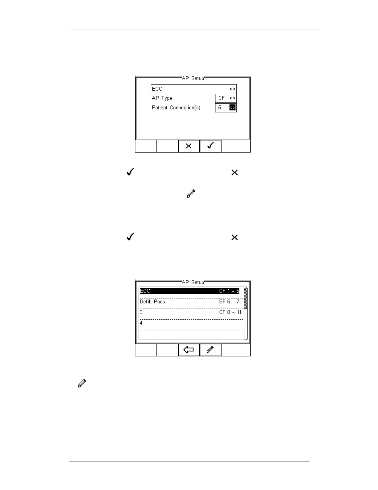
Rigel 288 plus Instruction Manual – Revision 1.1 - 67 -
Use up, down, left and right keys to set AP-type to CF and Patient Connections to 5
Below presents the AP Setup screen with the required changes.
Confirm with the button (F4) or exit using the button (F3).
Highlight Applied Part 2 and press the button (F2)
Repeat the actions above and select Defib Pads from the drop down box in the AP
Setup screen. Set the AP type to BF and Patient Connections to 2.
Confirm with the button (F4) or exit using the button (F3).
The following screen shows an example Applied Part Configuration still showing
Applied Part 3 (CF 8..11).
To delete Applied Part 3, highlight line 3 using the Up & Down Keys and press the
button (F2).
There are two options to delete an Applied Part.
Page 69
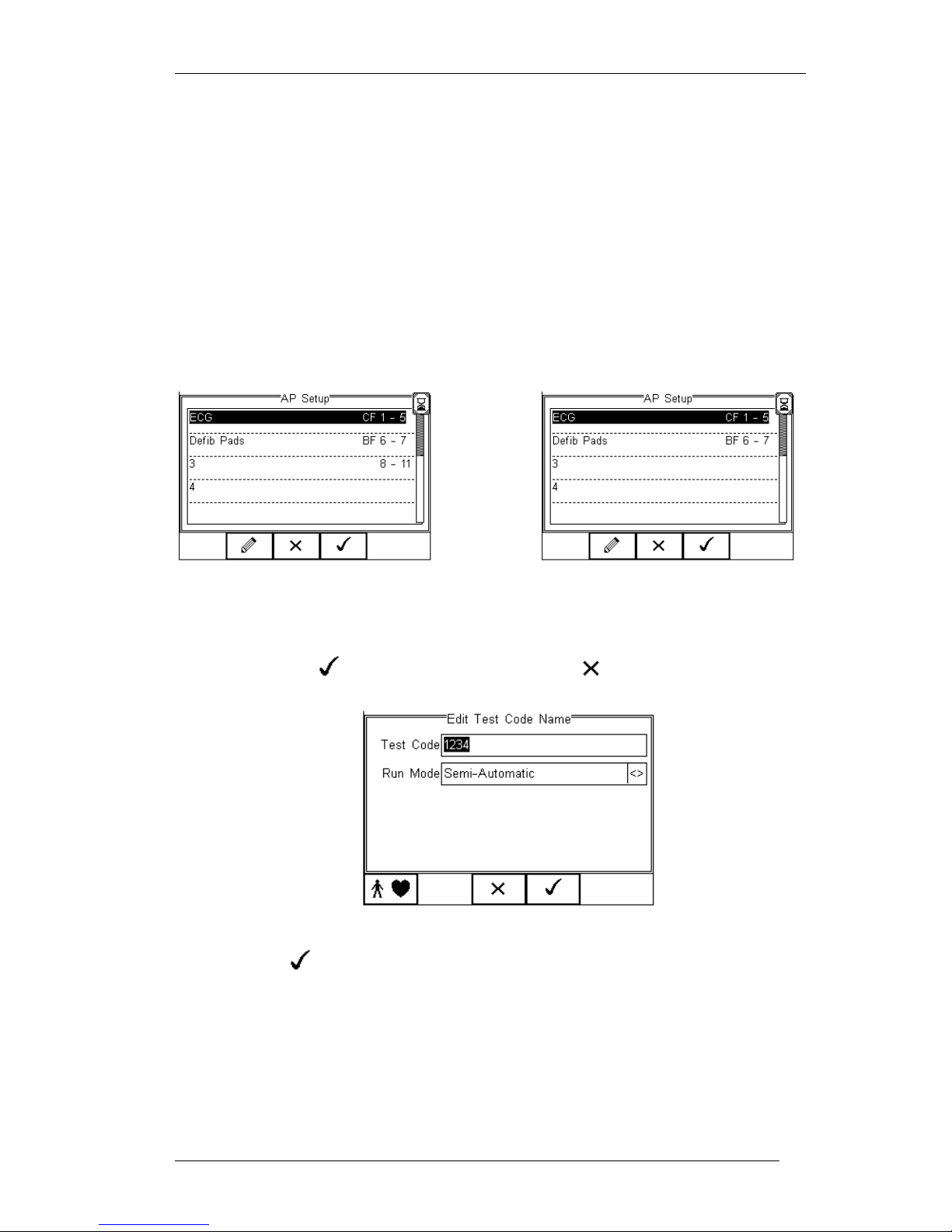
Rigel 288 plus Instruction Manual – Revision 1.1 - 68 -
Option 1:
Set the AP type to BLANK and leave the Patient Connections to 4; This would not
ignore Connections 8-11 in an electrical safety test. However additional Applied Parts
are not possible as the maximum number of connections is 10.
This feature could be useful to blank a number of connections between Applied Parts
and can be done by inserting a BLANK AP type with an applicable number of
connections in between B, BF or CF Applied Parts.
Option 2:
Set the AP type to BLANK and the Patient Connections to 0; This would delete the
whole Applied Part and free up the remaining connections.
Option 1 Option 2
Confirm with the button (F4) or exit using the button (F3).
When returning to the Edit Test Code Name screen, cnfirm and save the Test Code by
pressing the button (F4), see below.
Be aware, pressing the Escape button (F3) would return to the initial test code screen
and default settings. All information will be lost.
Test Code 1234 has now been configured and saved. The screen below shows the
available Test Code(s) and is / are available for use in the Automatic test mode. (see 4)
Page 70
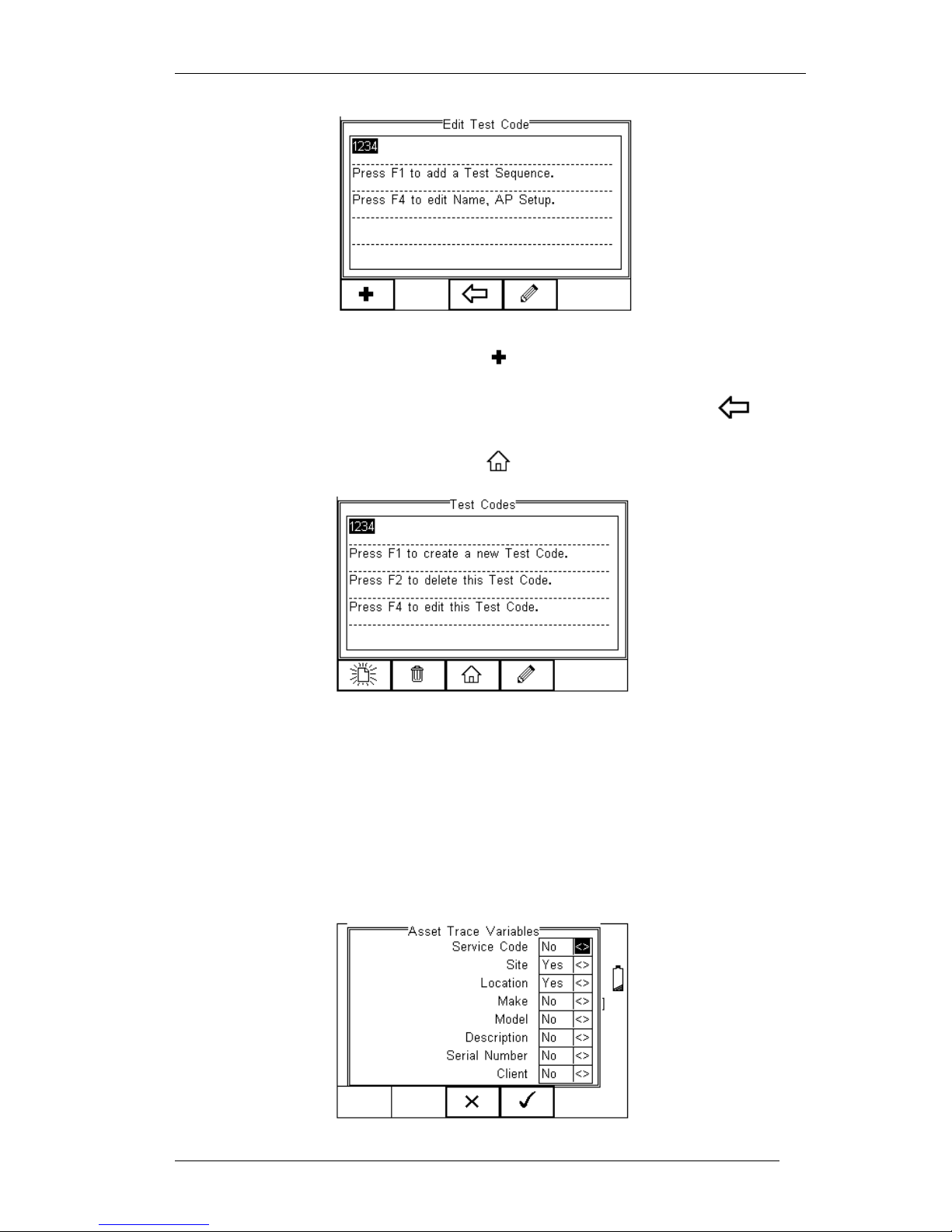
Rigel 288 plus Instruction Manual – Revision 1.1 - 69 -
To create further Test Codes, press the button (F1) and repeat the actions as
decribed in 6.2.1
Once all Test Codes have been completed, save all data by pressing the button
(F3) and confirm the changes made.
To return to the Home Screen, press the button (F3) see below.
6.3. Asset Trace Variables
The Asset Trace Variables allow the user to include valuable data to the test results to
enhance the traceability and to provide increased search criteria when using database
software. Asset trace variables may consist of a maximum of 25 characters and can be
selected prior to each electrical safety test when using the Rigel 288 plus in automatic
mode. The following variables can be added to the test results:
Page 71
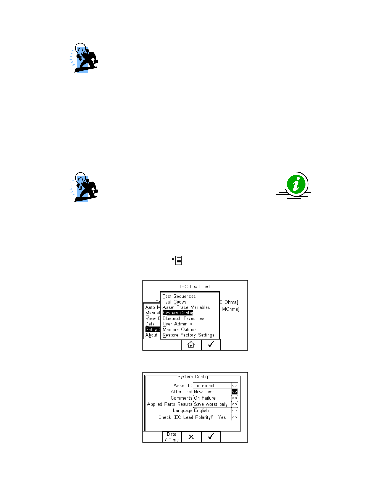
Rigel 288 plus Instruction Manual – Revision 1.1 - 70 -
See 6.4.1 for more information on the use of Asset Trace Variables.
The default settings on the Rigel 288 plus include the Site and Location variables. Both
are activated. The drop down box is set to [Yes].
To activate or de-activate each variable, use the up and down keys to select the
variable and the left and right keys to select yes or no.
Once a variable has been activated, the user is given the ability to enter Trace
Variables prior to a safety test by selecting from or adding to the list of default items.
Each variable entered during the automatic test will automatically be added to the list for
future use.
Trace Variables that are de-activated (set to NO) will not appear during the automatic
tests.
A maximum of 40 individual entries are available for each
Trace Variable. Additional entries will overwrite on a first in
first out basis.
6.4. System Config
This feature can setup the Rigel 288 plus to automatically perform certain features
during or after a test as well as allowing the user to set Time and Date preference.
To select System Config, press the button (F4) followed by Setup in the menu and
System Config from the list as shown below;
The System Config menu is displayed below;
Page 72
Rigel 288 plus Instruction Manual – Revision 1.1 - 71 -
The System Config menu provides the following features:
6.4.1. Asset ID
Provides automatic Asset ID configuration. Use the Left & Right Keys to select between
Increment - Automatically increments the next Asset ID’s least significant
number by 1
Blank – Will leave the next Asset ID field blank
Repeat Last - Will copy the previous Asset ID into the next Asset ID field
The Asset ID field is used to store (and identify) the record in the Rigel
288 plus database. Additional input fields, referred to as ASSET TRACE
VARIABLES are available to distinguish between identical Asset ID
records, ie when the ASSET ID field is used to enter the Model or 4 digit
fast code. The benefit of using the Rigel 288 plus in this way is that
similar items can be easily retested using the same parameters. When an existing
ASSET ID is entered in the 288 plus, the tester will automatically configure itself to reperform the test without any additional settings being required. By using ASSET TRACE
VARIABLES, each ASSET can be given a unique identifier in the database ie through
the use of a serial number. A representation is provided below;
Asset Trace Variables
Asset ID
(database
record)
Service
code
Site
Location
Make
Model
Description
Serial
Number
Client
001
PPM
Site 1
Loc 1
JBM
X3000
ECG
1234er
NHS
001
PPM
Site 1
Loc 1
JBM
X3000
ECG
5678ty
NHS
001
PPM
Site 1
Loc 1
JBM
X3000
ECG
0986gh
NHS
Identical ASSET RECORDS are also differentiated by TIME/DATE stamp, thus
ensuring no records are overwritten.
6.4.2. After Test
Provides automatic action after a test is completed. Use the left and right keys to select
from the following
New Test – Automatically brings up the next test screen.
Download – Automatically down loads the test results to the PC (see 8.1)
Print Label – Automatically prints the test results to a thermal printer
Test ‘n Tag – Automatically prints a Test ‘n Tag label. (see 4.7)
Options Menu – Provides a menu to allow further choices after a test. (see 4.8)
Page 73

Rigel 288 plus Instruction Manual – Revision 1.1 - 72 -
6.4.3. Comments
Provides the ability to enter further comments after successful or failed tests. Use the
left and right keys to select from the following
Always – Comment field is displayed after each passed or failed test.
On Pass – Comment field is displayed after a passed test only.
On Failure – Comment field is displayed after failed test only
Never – Comment field is not displayed.
6.4.4. Applied Part Results
Provides the ability to change the amount of patient leakage data stored to save
memory and keep reports short and relevant. Use the Left & Right Keys to select
between
Save Worst Only – Automatically saves the patient connection within an applied
part with the highest reading for a specific normal or single fault condition
provided all patient connections pass the test.
Save All – All patient connections in all applied parts are saved.
6.4.5. Language
Provides the ability to change the default language in the Rigel 288 plus. A total of 6
languages are available;
English
German
French
Spanish
Italian
Turkish
Use the up, down, left and right keys to select from the available languages. Additional
languages can be made available, please contact our support office at +44 (0) 191
5878701.
6.4.6. Check IEC lead Polarity
Provides the ability to set the Rigel 288 plus for polarised (eg UK 3-pin) or non-polarised
(eg Schuko 2-pin) mains supplies.
Yes - Automatically checks for incoming mains reversal and includes a Live
Neutral polarity check during an IEC lead test. The Rigel 288 plus will display a
message during power-up in case incoming mains is reversed
No – Incoming mains reversal and IEC polarity checks are disabled. No mains
reversal messages are displayed at power-up.
Page 74
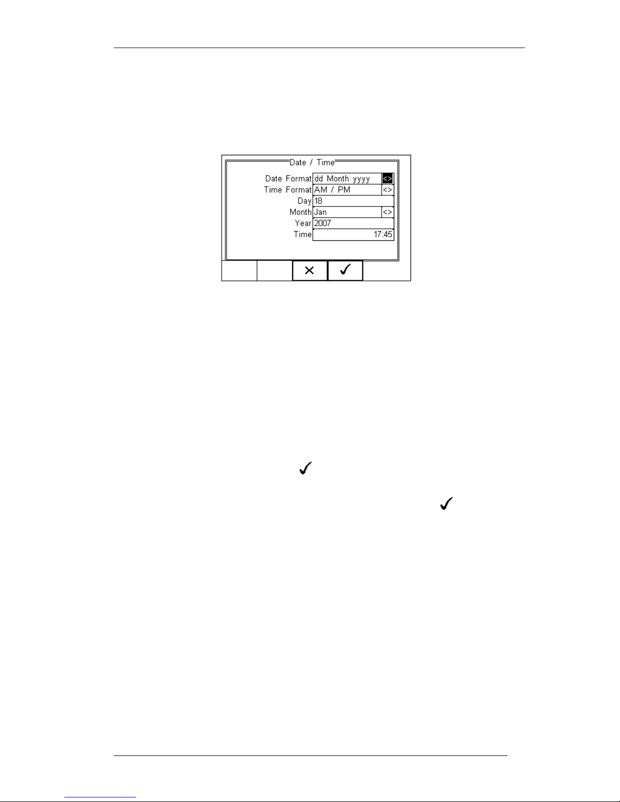
Rigel 288 plus Instruction Manual – Revision 1.1 - 73 -
6.4.7. Date / Time
Allows the user to set the current date / time and preferred formats.
Press the Date / Time button (F2). The following menu will be displayed;
Date Format: Use the Left & Right Keys to set the date format to
dd Month yyyy or mm / dd // yyyy
Time Format Use the Left & Right Keys to set the time format to
AM / PM or 24 hour
Day Enter current day
Month Use the up, down, left and right keys to select the current month
Year Enter current year
Time Enter current time. Use the ‘:’ (F1) to separate hours from
minutes to ensure the correct time is entered and saved.
Confirm the settings by pressing the button (F4)
Ones all System Configurations have been completed, press the button (F4).
Changes are saved automatically.
6.5. Blue Tooth Favourites
In order for the Rigel 288 plus to automatically connect to the correct Bluetooth
accessory, details of that accessory must be entered into the Bluetooth Favourites list.
The Bluetooth Favourites list comprises of three sub-lists (device types), each of which
can store up to 3 accessories of the same type. The three sub-lists are shown below:
Barcode (Scanner)
Printer
Computer
Page 75
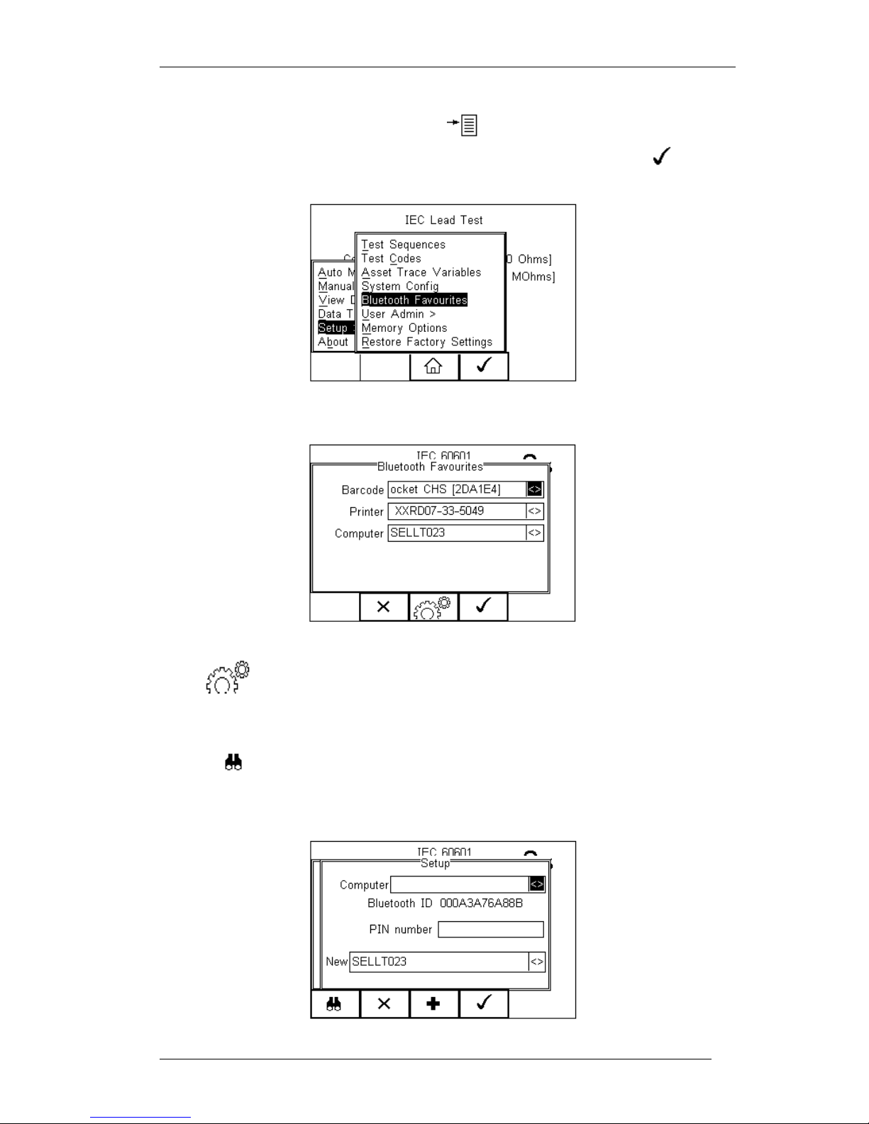
Rigel 288 plus Instruction Manual – Revision 1.1 - 74 -
To select Bluetooth Favourites, press the button (F4) followed by Setup in the
Menu and Bluetooth Favourites from the list as shown below. Press (F4) to
select;
The following shows how to add a Computer to Bluetooth Favourites.
Use the up/down arrow keys to highlight the device type (in this case Computer) then
press (F3).
Make sure that the device you want to add to your new favourites is switched on.
Press (F1). The Rigel 288 plus will search for all discoverable Bluetooth
devices within a 10m range. The time taken to perform the search will vary depending
on the number of Bluetooth devices in range.
Page 76
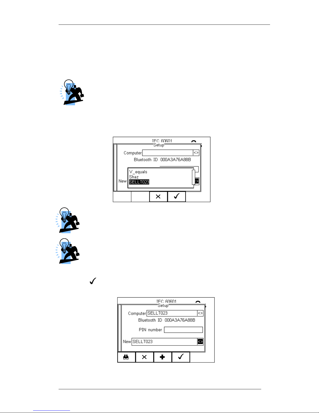
Rigel 288 plus Instruction Manual – Revision 1.1 - 75 -
Wait for the progress bar to complete.
Use the arrow keys to highlight the field labelled “New” and press the left or right keys
to open the list of devices which have been found during the search.
If more than 10 Bluetooth devices have been found the list will show
the last 10 devices found.
In the following example, the search has identified Bluetooth devices named
“SELLT023”, “Shaz” and “V-equals”
If the required device is not shown, check that it is powered on with the
Bluetooth function active then repeat the search.
Some Bluetooth devices do not report a recognisable name and may
cause confusion when setting up Favourites. Turn off or disable unused
Bluetooth devices when configuring Favourites.
Use the up/down keys to highlight the required device (in this case SELLT023i) and
press the button (F4). SELLT023 is now placed in the “New” field as shown
below.
Page 77
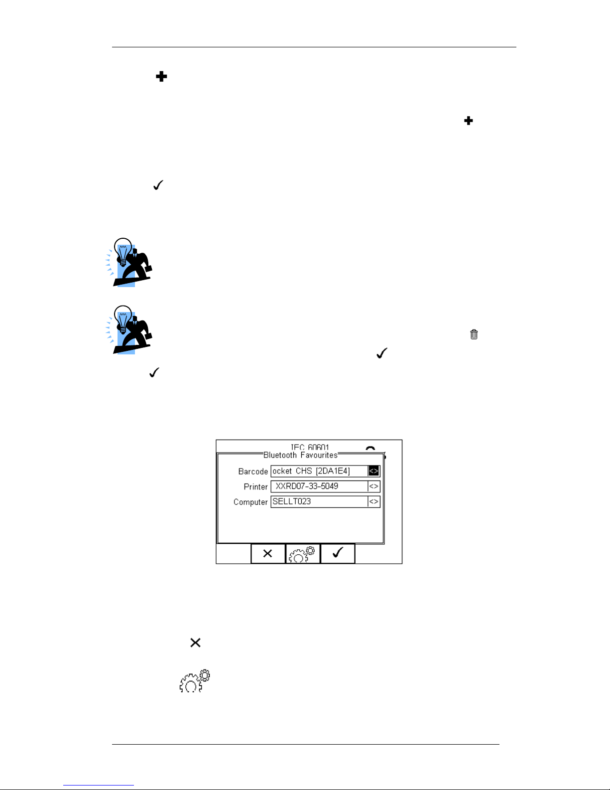
Rigel 288 plus Instruction Manual – Revision 1.1 - 76 -
Press (F3) to add SELLT023 to the Favourite Computer list.
To add further devices to the list of available computers select the new field again, use
the up, down, left and right keys to select the required device and press (F3) to
add the chosen device.
“SELLT023” has been added to the Computer field with Bluetooth ID.
Press (F4) to store the changes and return to the previous screen.
A PIN number can be entered if required for the device to be added to the Favourites
list.
Seaward and Rigel accessories do not require a PIN. For other
Bluetooth devices refer to the manufacturer’s documentation.
Devices that are not required can easily be removed by selecting the
Computer field, pressing the left of right keys to open the list,
highlighting a device using the up/down keys and pressing (F2).
Confirm the deletion by pressing the button (F4). Press the
button (F4) to save Bluetooth Favourites settings.
All Bluetooth devices have a unique ID. The Bluetooth ID is shown when a device
is added to the Favourites list.
“SELLT023” is now
a Bluetooth
Favourite and the Rigel 288 plus will automatically establish a connection with
“SELLT023” when using functions that communicate with a computer e.g. downloading
records to a PC database software package.
Note: Press (F2) to exit without saving changes.
Press (F3) if necessary, to select another device..
Page 78
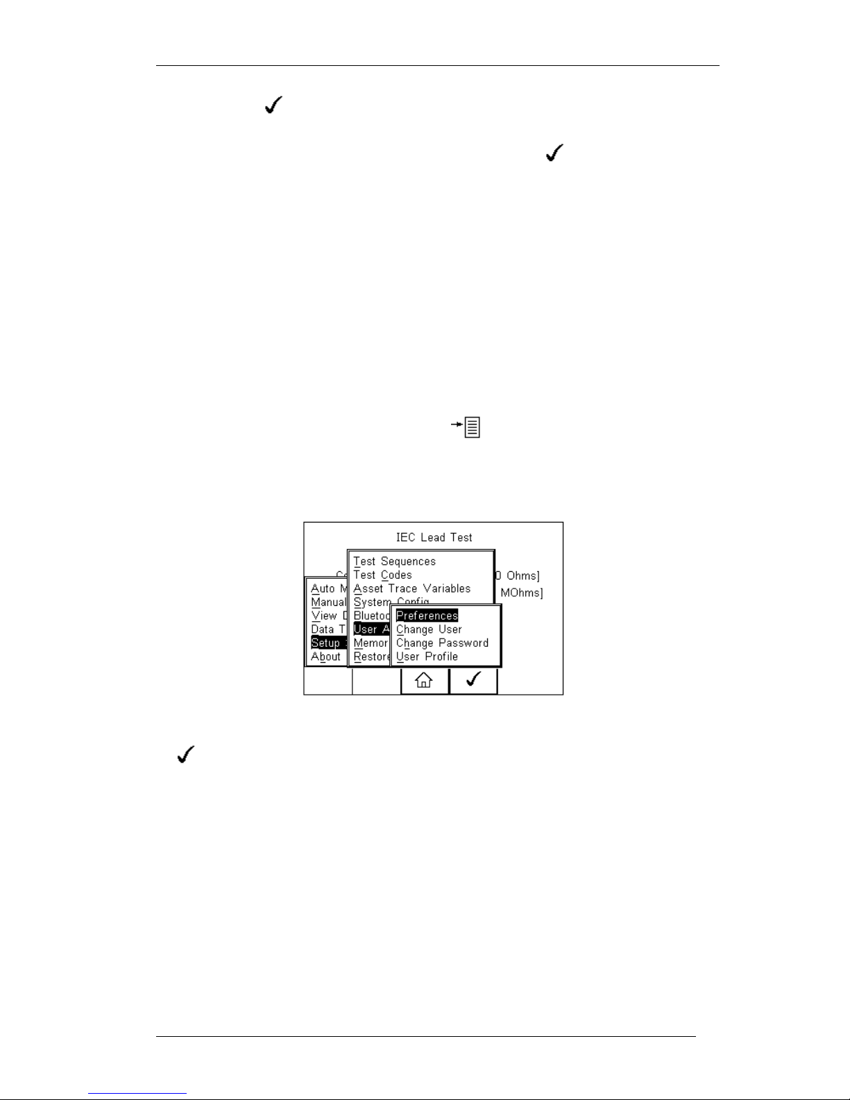
Rigel 288 plus Instruction Manual – Revision 1.1 - 77 -
Press (F4) button to save changes.
When all your favourite devices have been set up, press (F4) and they will be
saved.
6.6. User Admin
The User Admin feature allows the user to personalise the way in which the tester
behaves during normal use and include features such as:
Preferences (see 6.6.1)
Change User (see 6.6.2)
Change Password (see 6.6.3)
User Profile (see 6.6.4)
To enter the User Admin feature, press the button (F1) from the home screen,
select Setup followed be User Admin.
The following menu will appear:
Navigate through this menu using the Up & Down Keys and select by pressing the
button (F4) or the right arrow key.
Page 79
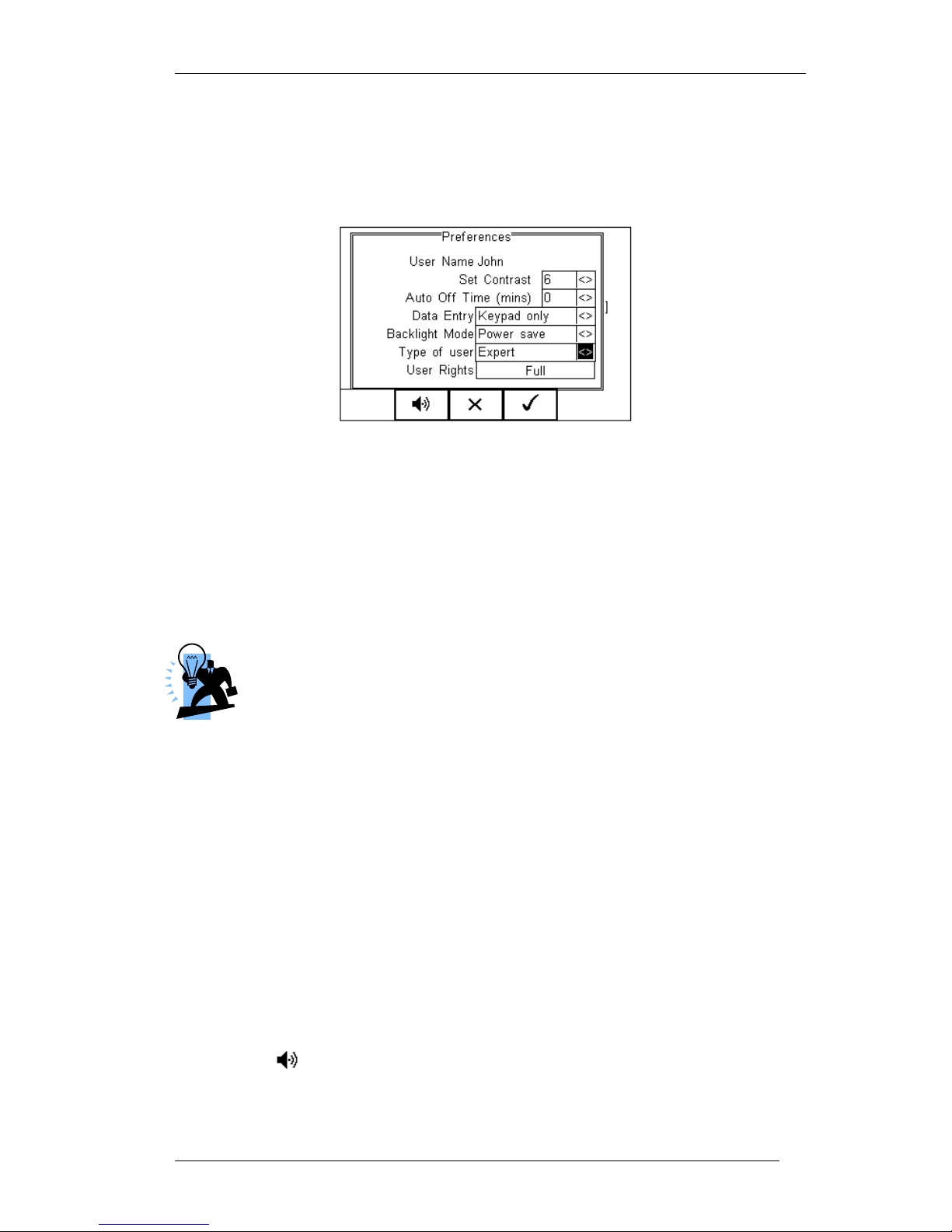
Rigel 288 plus Instruction Manual – Revision 1.1 - 78 -
6.6.1. Preferences
Provides means of configuring the default settings of the tester’s behaviour during
normal use. All settings are user specific and stored against the logged-in user :
Set Contrast – Use the up, down, left and right keys to set the contrast
Auto Off Time (mins) - Use the up, down, left and right keys to set the
power off time on the tester. Settings between 0- 10 minutes. Note 0 minutes will
deactivate the AutoSwitch Off feature.
Data Entry – Sets the tester up to take data entry from Barcode or Keypad only.
Use the up, down, left and right keys to select Barcode or Keypad only.
In data entry mode the unit will automatically try to connect to a barcode
scanner via the internal Bluetooth module – if the scanner is available this
feature will drain the batteries u-necessarily. In this instance it is recommended
that the unit be set to Keypad only.
Backlight Mode – Chose between Always Off, Always On, Power Save (Back
light on for 30 secs after each key press). Use the up, down, left and right keys
to select.
Type of User - Use the up, down, left and right keys to select between Novice
and Expert. Novice users benefit from additional instructions throughout the
safety tests. The Expert setting removes those additional instructions. These
instructions are:
1 Warning message before the first Insulation test in auto mode
2 Warning message before the first EUT power on in auto mode
3 Warning message if user tries to execute a Test Code that has missing
test sequences.
User Rights – For information only. To change the user rights, see 6.6.4
The (F2) button allows the user to set the audible warnings and beep on
key presses. See menu below:
Page 80
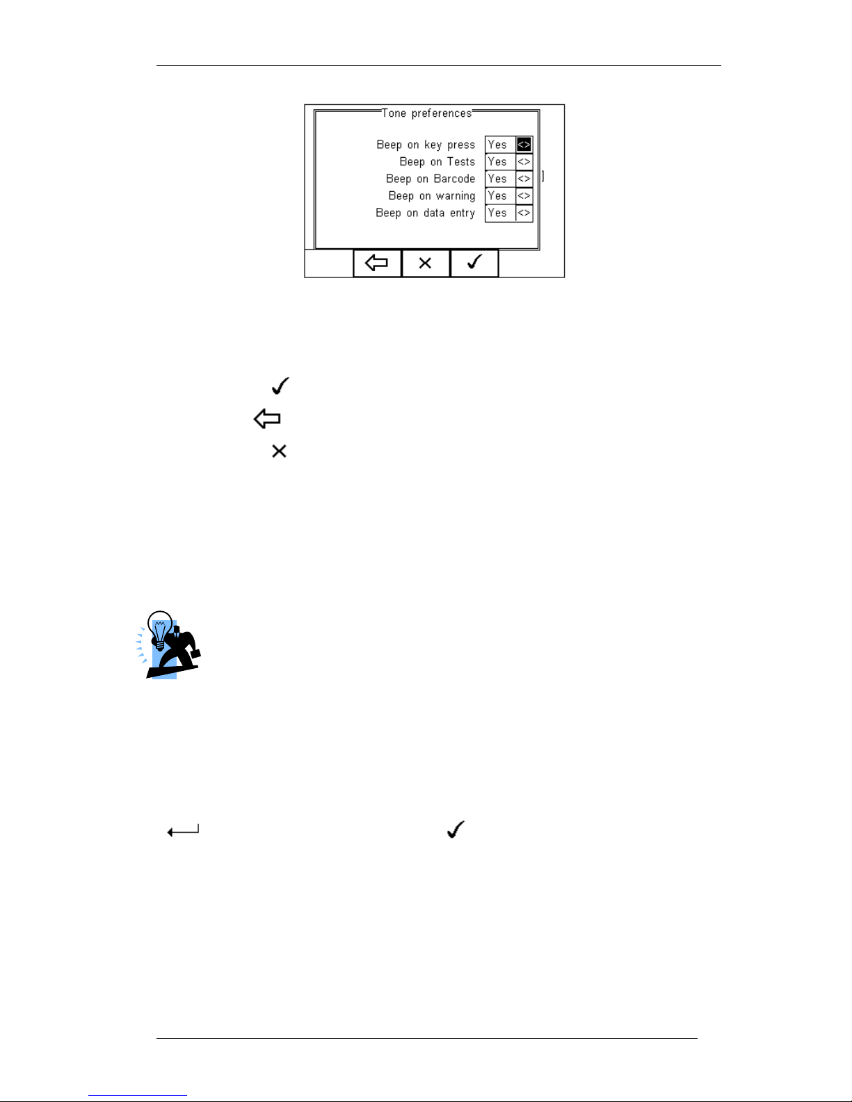
Rigel 288 plus Instruction Manual – Revision 1.1 - 79 -
Navigate using the Up & Down Keys and change between Yes / No using the
left key.
Confirm the settings using:
o button (F4) this will return to the Home screen
o button (F2) will return to previous menu and save data.
o button (F3) will return to the home screen without changes
being saved.
6.6.2. Change User
This feature allows an operator to default to a different existing user or setup a new
user. Admin rights are required for this feature. Alternatively, new users can be created
in the User Profile menu, see below.
A brand new Rigel 288 plus will automatically default to admin rights so
new users can be created.
6.6.3. Change Password
This feature allows a new password to be assigned or changes to an existing password.
To create a new password, highlight the New Password field using the Up & Down Keys
and enter a new password followed by confirmation of the new password. Use the
key (F4) to finish and press the button (F4) to confirm and save the
new password.
To change an existing password, enter current password and repeat the steps above.
See menu below for an overview of the Change Password screen.
Page 81
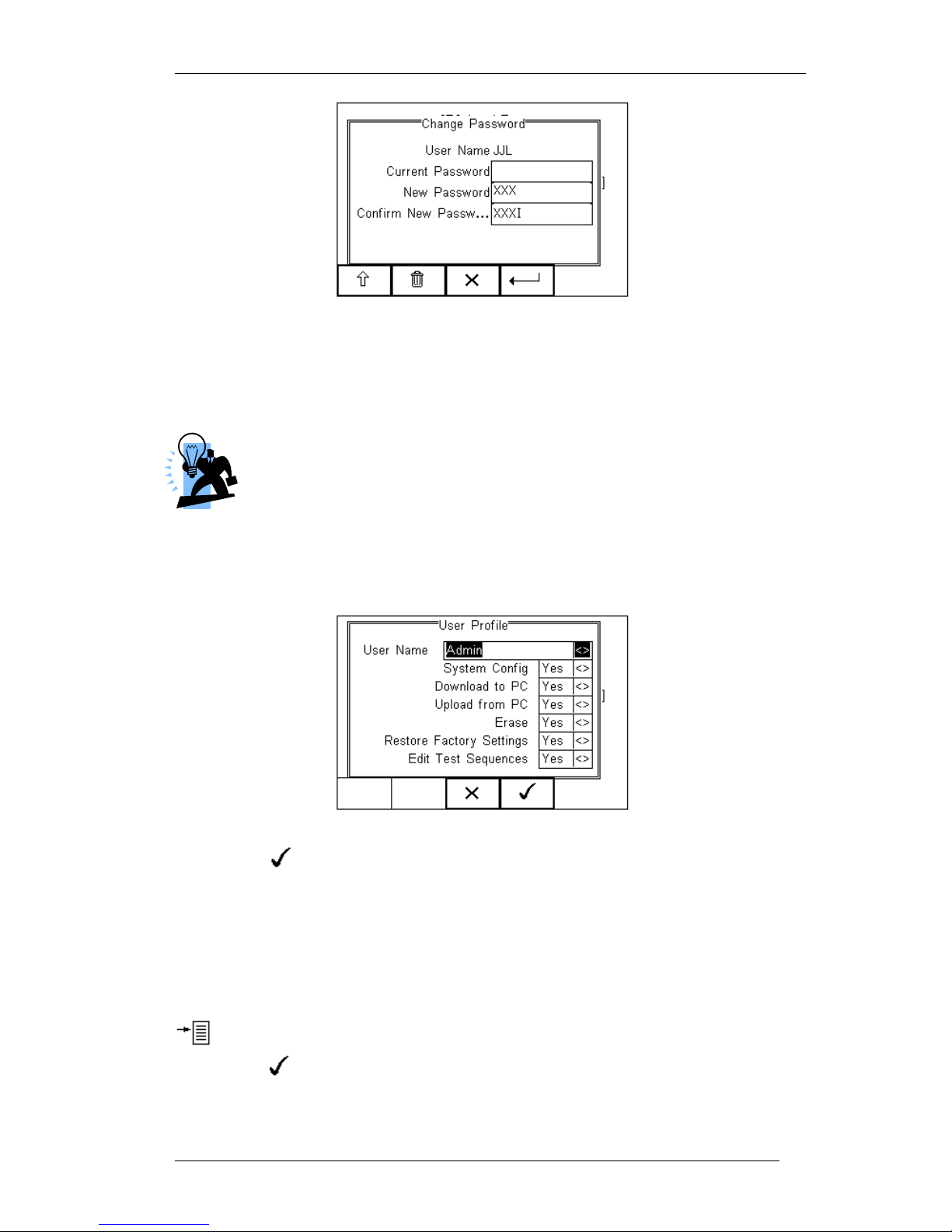
Rigel 288 plus Instruction Manual – Revision 1.1 - 80 -
6.6.4. User Profile
This feature allows the administrator to setup new and existing users and inhibit or
assign certain feautures to individual users.
That the User Profile is only valid when the ADMIN user has been setup
with a PASSWORD. See item above. If no ADMIN password has been
set, all users have FULL User Rights.
Select the applicable user name, use the Up & Down Keys to navigate through the
menu, use the Left & Right Keys to activiate (yes) or de-activate (no) certain features.
See menu below.
Press the button (F4) to save user profile.
6.7. Memory options
This feature is used to view information about the Rigel 288 plus memory status. Press
(F4), select setup using the up/down keys and select Memory Options by pressing
the press (F4) to accept.
Page 82
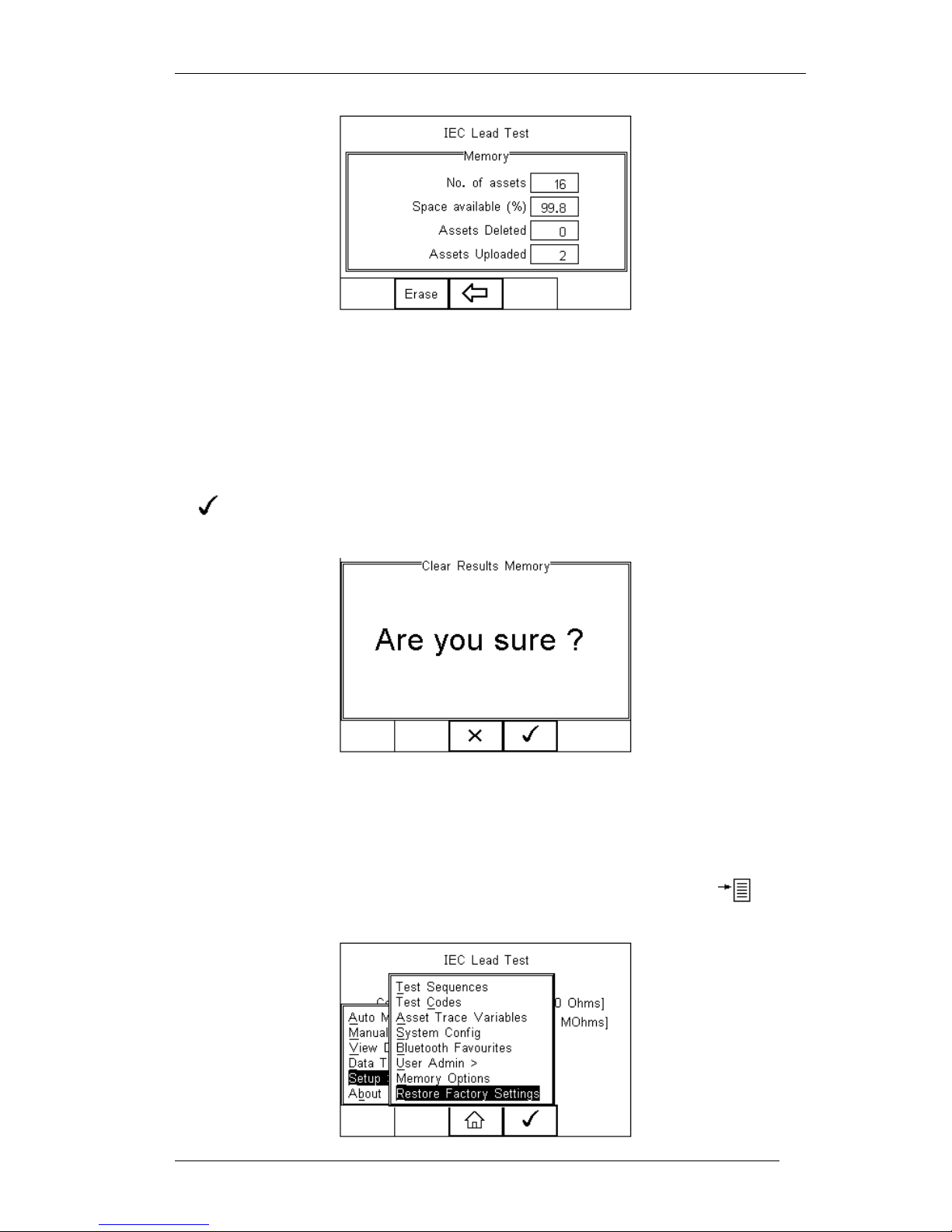
Rigel 288 plus Instruction Manual – Revision 1.1 - 81 -
The display shows the number of asset records currently stored, the remaining memory
space, number of assets deleted and number of assets in upload memory.
The nature of Flash memory is such that when records are deleted only the reference to
the data is removed. The data still remains and will use memory space. The memory
must be erased in order to release memory used by deleted records.
If the Erase (F2) key is pressed, a prompt is shown below. To erase the memory press
button (F4).
6.8. Restore Factory Settings
The factory settings can be restored at any time using this function. Press button
(F4). Select Setup followed by Restore Factory Settings.
Page 83

Rigel 288 plus Instruction Manual – Revision 1.1 - 82 -
All the settings provided within the Setup menu will default to Factory Settings including;
All Asset Trace Variables, Test Sequences, User Admin, Test Codes and System
Config.
Warning: Restore Factory Settings cannot be undone and will remove all the
customised items described above.
All customised settings within Setup can be cloned to a PC. We advise that
this is done on a regular basis to ensure custom settings are saved for
back-up. See 7.4 for further details on Cloning.
Page 84
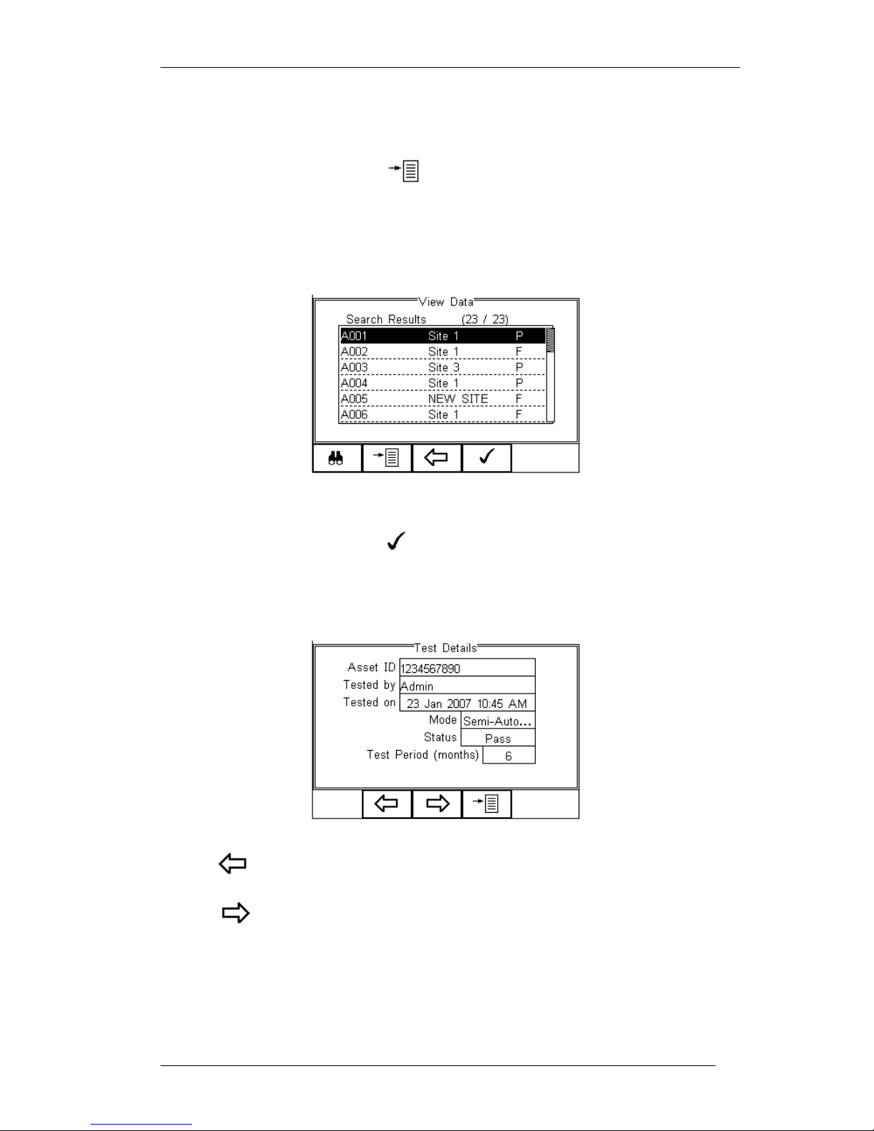
Rigel 288 plus Instruction Manual – Revision 1.1 - 83 -
7. View Data
To view the stored data, press the button (F4) and select View Data from the
menu.
The following screen provides an overview of all available records in the memory,
identified by Asset ID, Site and Pass or Fail.
Use the up and down arrow keys to scroll through the database. When the desired
record is highlighted, press the button (F4) to enter the record and view the
data.
This will display the Test Details Screen
Use the button (F2) to return to the main View Data screen.
Use the button (F3) to view the Trace Variable and again to view the Applied Part
setup. See below.
Page 85
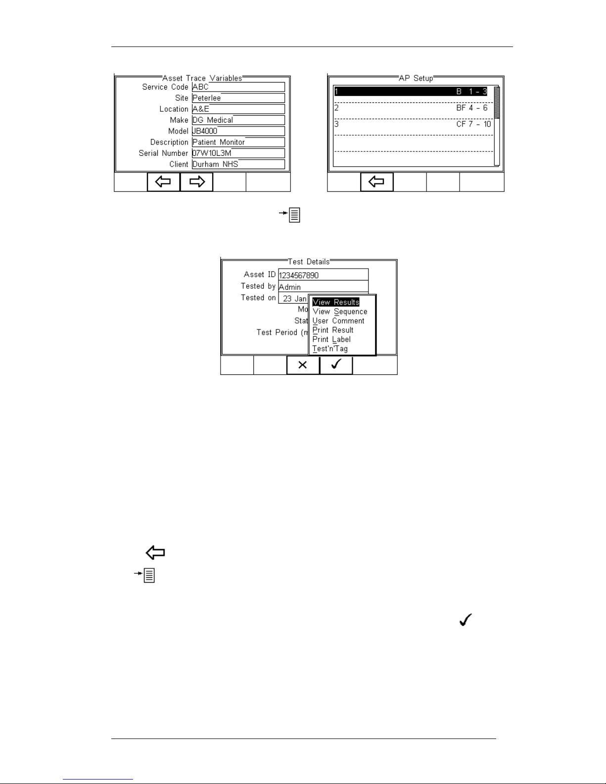
Rigel 288 plus Instruction Manual – Revision 1.1 - 84 -
In the Test Details screen, press the button (F4) to view the following options:
View Results will display the results of the test (see section 7.1)
View Sequence will display the test Sequence
User Comment will allow the user to enter comments if required
Print Result will print the result on the thermal printer (50 mm roll)
Print Label will print a pass/fail label on the thermal printer (50 mm roll)
Test ‘n Tag will produce a thermal transfer pass/fail label. (see section 4.7 for
more information)
7.1. View Results
Us the button (F2) to return to the Test Details screen.
The button (F4) provides the user with extra options to print results, print labels,
Test ‘n tag print or view results.
Use the up and down keys to select the view results option. Press the button
(F4) to display the view text results screen (see below).
Page 86
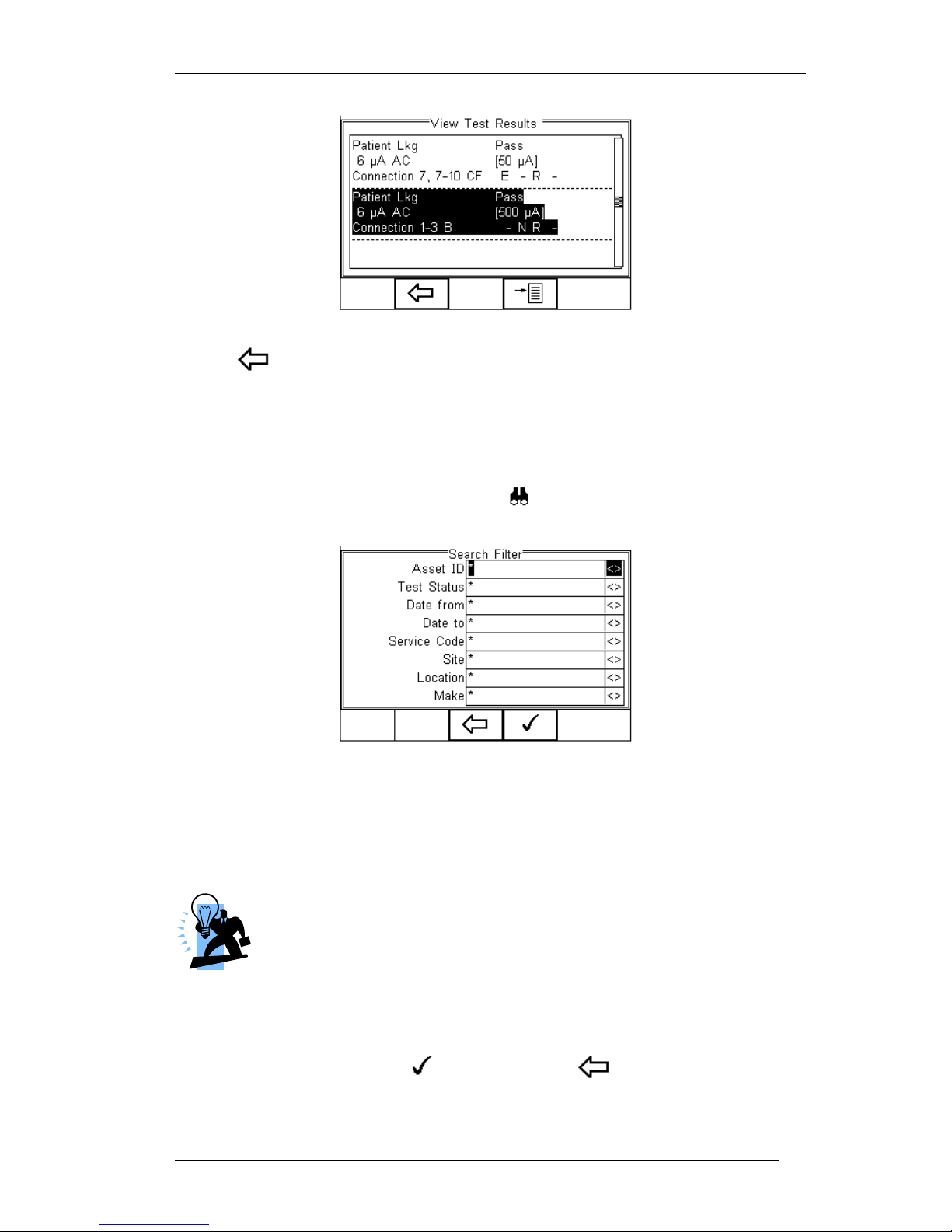
Rigel 288 plus Instruction Manual – Revision 1.1 - 85 -
Use the button (F2) to return to main menu.
7.2. Search the database
From the main View Data screen, press the button (F1).
Use the up, down, left and right keys to navigate this screen.
The default setting is ‘*’ which includes all records that Passed.
To search for more specific criteria, fill in the required fields by either using the
keyboard or drop down boxes.
The entered data must be identical to the data stored with the test.
This includes visible and invisible SPACE characters.
For Date entry use format DDMMYYYY or DD MM YYYY. For example
for 31st October 2007 us 31102007.
Test Status Allows the user to select search criteria based on PASSED, FAILED or
UPLOADED items.
To start the search, press the button (F4) or the button (F3) to leave this
screen.
Page 87
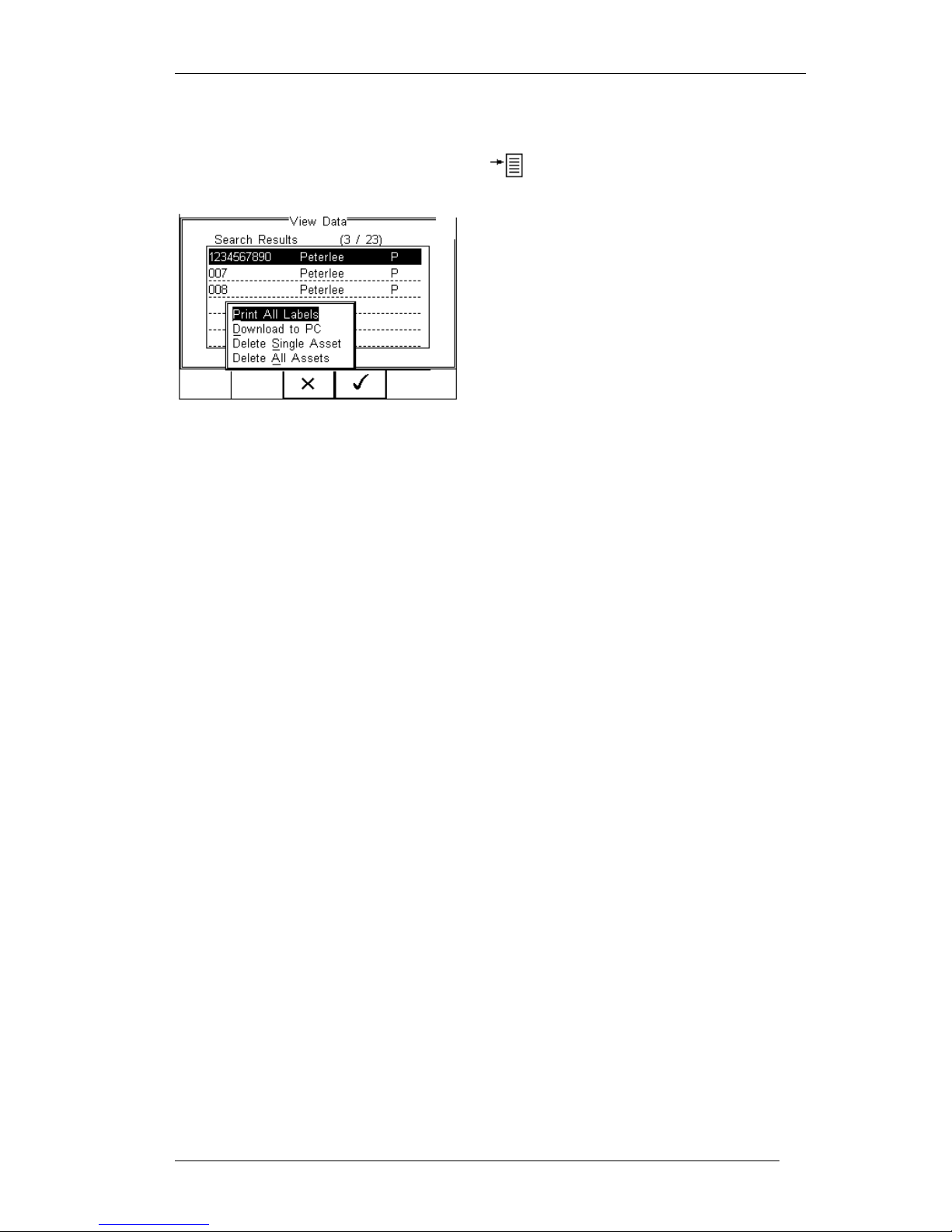
Rigel 288 plus Instruction Manual – Revision 1.1 - 86 -
7.3. View Data Options
From the main View Data screen, press the button (F2).
This will present an options menu to allow
the user to:
Print All Labels – Will download all records
within the search criteria to the Test ‘n Tag
printer, setup in Bluetooth favourites.
Download to PC – Will download all records
within the search criteria to the PC, setup in
Bluetooth favourites.
Delete Single Asset – Will delete the single
selected record.
Delete All Assets – Will delete all records
from the memory (this action is irreversible).
Page 88
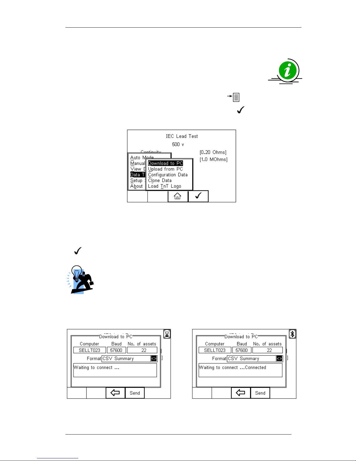
Rigel 288 plus Instruction Manual – Revision 1.1 - 87 -
8. Data Transfer
Data transfer is used to transfer records and configuration data to and
from a PC load a logo in bitmap format for use with the Seaward Test ‘n’
Tag print system, and clone data.
The Data Transfer functions are accessed by pressing the button (F4), selecting
Data Transfer using the up and down keys and pressing the button (F4).
8.1. Download to PC
This feature is used to download records to a PC. Select Download to PC and press the
button (F4) to accept.
Later versions of firmware (V2.24 and higher will offer RS232 connectivity
as alternative to Bluetooth. If an RS232 cable is used, please default to a
baud rate of 9600. A higher baud rate may result in incorrect data being
transmitted.
The Rigel 288 plus will now attempt to make a Bluetooth connection with the Computer
that has been configured in the Bluetooth Favourites.
Initially, the Bluetooth status icon will display the egg timer for a few seconds, as shown
Page 89
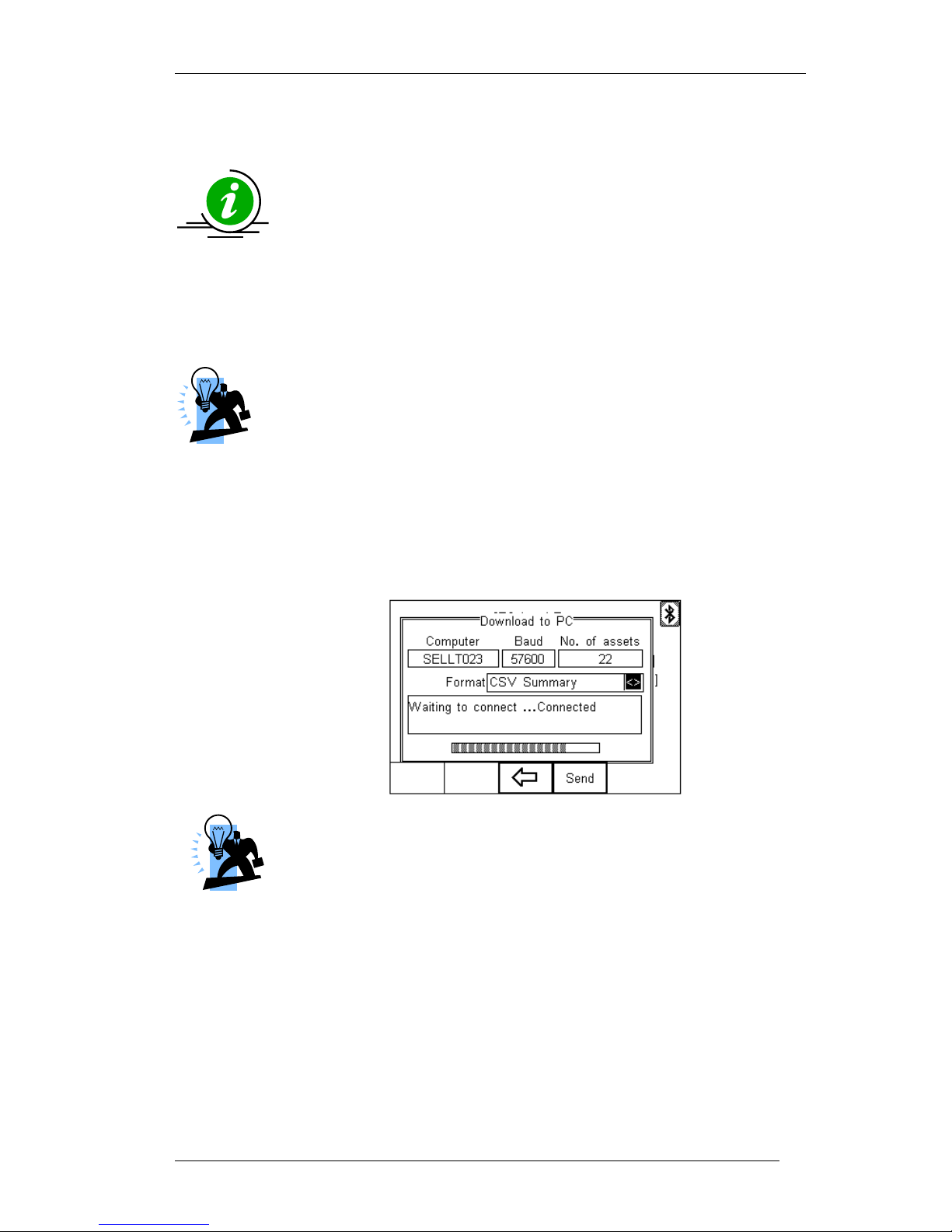
Rigel 288 plus Instruction Manual – Revision 1.1 - 88 -
on the left, while the connection is established. When the connection is established and
ready to communicate the Bluetooth status icon will change to show the Bluetooth icon
as shown on the right.
The Rigel 288 plus is able to download in a number of formats to suit
individual requirements. These are;
CSV Full (Comma Separate Value, download only)
CSV Summary (Comma Separate Value, download only)
Rigel SSS (Up and download format)
Toggle between the options by using the left and right arrow keys.
Details on the RS232 format are available. Please contact our support
department at +44(0) 191 5878701.
The Rigel 288 plus is now ready to transfer data. The No. of assets field shows the
number of records that will be downloaded. Ensure that the PC application is ready to
receive data then press the Send button (F4).
A progress bar, as shown below, will now follow the data transfer until download is
complete.
To download a selection of the database, refer to “View Data”
(section 6). Search on the required criteria then select “download to
pc” from the options menu.
Page 90
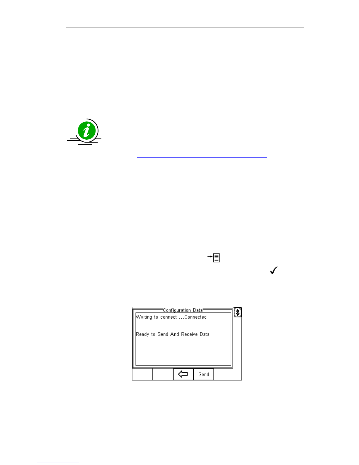
Rigel 288 plus Instruction Manual – Revision 1.1 - 89 -
8.2. Upload from PC
This feature is only available when used in combination with the new Med-eBase PC
software and when the SSS format is activated on your device.
Select the Upload from PC option from the Data Transfer menu. The Rigel 288 plus will
now attempt to establish a Bluetooth connection to the PC as previously described in
Download to PC. The Rigel 288 plus is now ready to receive upload data from a PC.
Refer to the Instruction manual of Med-eBase on how to transmit data from the PC.
To activate the .SSS format on your Rigel 288 plus tester, please
download the SSS Application note from our knowledge base.
Please visit; http://www.rigelmedical.com/rigel-downloads
8.3. Configuration Data
This feature can be used to transfer store or modify the current Trace Variables, User
Profiles and Comment lists to/from a PC. It can be used to configure a number of Rigel
288 plus units with identical Trace Variable, User Profile and Comment lists.
8.3.1. Send Config Data
To send configuration data from a PC, press the button (F4), and select Data
Transfer using the up and down arrow keys, select Data and press the button
(F4). The Rigel 288 plus will now attempt to connect to the PC, setup in the Rigel 288
plus Bluetooth Favourites. When a connection has been established the display will be
as shown below.
Open the Bluetooth Downloader (Data Transfer.exe) application on your PC and check
that the Com Port is correct for the Bluetooth USB adaptor being used with the P.C. The
baud rate will default to the correct value of 57600. If an RS232 cable is used, please
Page 91
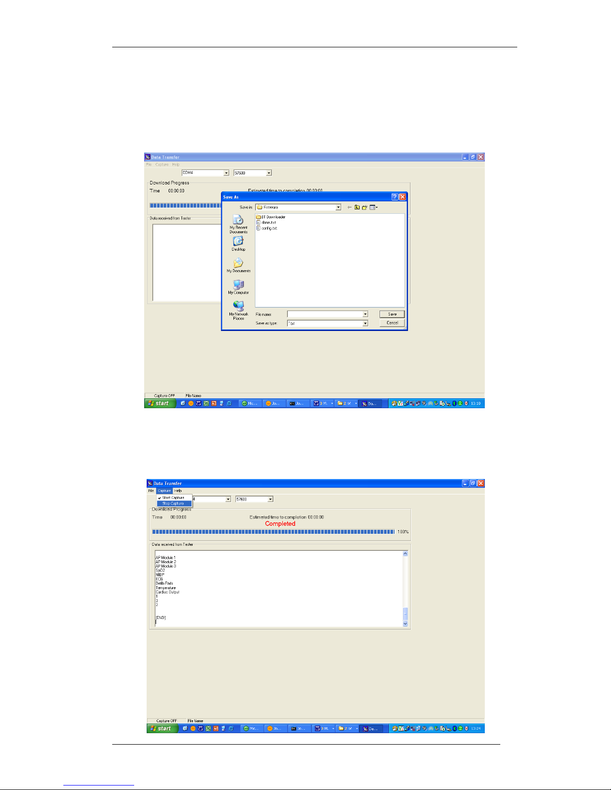
Rigel 288 plus Instruction Manual – Revision 1.1 - 90 -
default to a baud rate of 9600. A higher baud rate may result in incorrect data being
transmitted.
In the application, select Start Capture from the Capture menu in the task bar.
Enter a valid file name for the text file containing the download information; see below.
Once the text file has been created, press the Send button (F4) to transfer the Asset
Trace variables and User names from the Rigel 288 plus to the PC.
The downloaded text will appear in the Bluetooth Downloader screen. Select Stop
Capture from the Capture menu in the task bar. See below;
Page 92
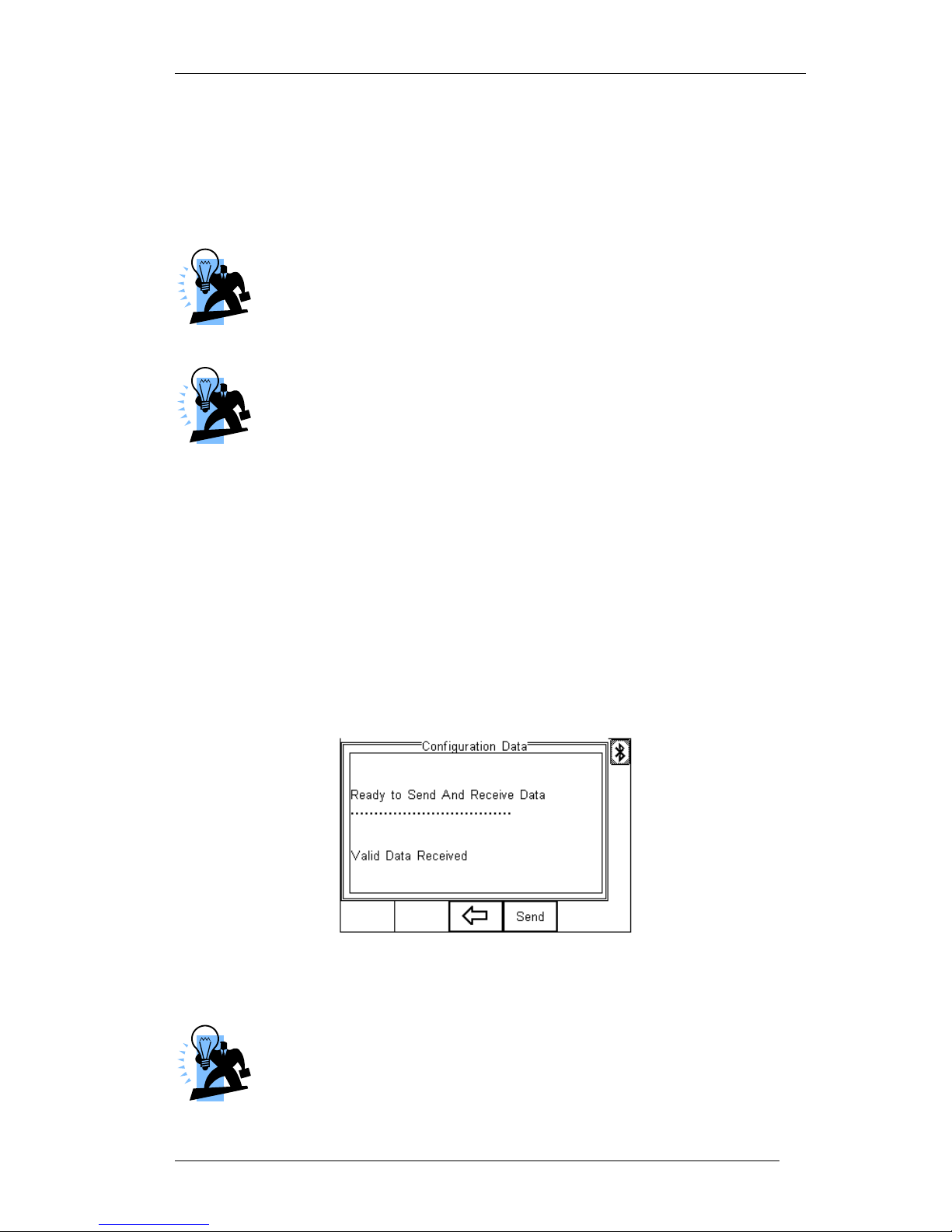
Rigel 288 plus Instruction Manual – Revision 1.1 - 91 -
Close down the Application and open the text file using word pad or equivalent.
The downloaded information can be used to ‘clone’ other Rigel 288 plus’s or modified to
add additional trace variables. Again these can be uploaded to any Rigel 288 plus for
convenience.
The file transfer can be made using any suitable PC application such
as the Seaward Bluetooth Downloader (Data Transfer.exe) or
Hyperterminal capable of sending and receiving a text file.
The maximum number of entries for each field is SiteName (40),
LocationName (50), UserName (40) and Comment (80).
8.3.2. Receive Config Data
Follow the steps above in Send Config Data to run the Bluetooth Downloader and
connect the Rigel 288 plus to your PC.
Click on File on the Bluetooth Downloader menu and select Send File. This will open a
window allowing you to select the text file containing your Trace Variables, User Profiles
and Comments configuration data. Select the require file and click on Open. The
Bluetooth Downloader will now transfer the configuration file to the Rigel 288 plus.
When the transfer is complete the Rigel 288 plus screen will display a message as
shown below.
If the transfer is not successful, check that the format of the configuration file exactly
matches that specified.
The Config file must be ASCII text and the last entry must be the
[END] statement.
Page 93
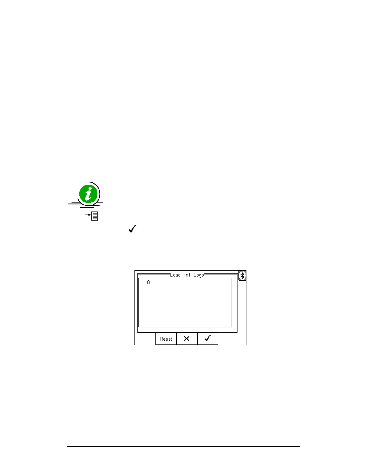
Rigel 288 plus Instruction Manual – Revision 1.1 - 92 -
8.4. Clone Data
This feature can be used to transfer, store and copy the current Test Sequences and
Test Codes to/from a PC. It can be used to configure a number of Rigel 288 plus units
with identical Test Sequences and Test Codes.
The process is identical to transferring the Configuration Data as mentioned above.
Due to the amount of data transferred, the Clone download will take longer than the
Configuration Data transfer.
8.5. Load TnT Logo
A bitmap logo can be transferred to the Rigel 288 plus for use with the Seaward Test ‘n’
Tag print system.
The logo must be in .BMP format with a maximum size of 320 pixels by
240 pixels.
Press button (F4), select Data Transfer using the up/down keys, select load T ‘n’ T
logo and press the button (F4).
The Rigel 288 plus will now attempt to connect to the PC, setup in Bluetooth Favourites.
When a connection has been established the display will be as shown below.
The Rigel 288 plus is now ready to receive data. The amount of data received is shown
numerically on the top left of the display (0 in the screen shot above).
When using the Bluetooth Downloader application, select Send File from the File menu
in the task bar. This will open a window allowing you to select the Bitmap file.
Select the required Bitmap and click on Open. The Bluetooth Downloader will now
transfer the file to the Rigel 288 plus.
When the transfer is complete the Rigel 288 plus screen will display a message as
shown below.
Page 94
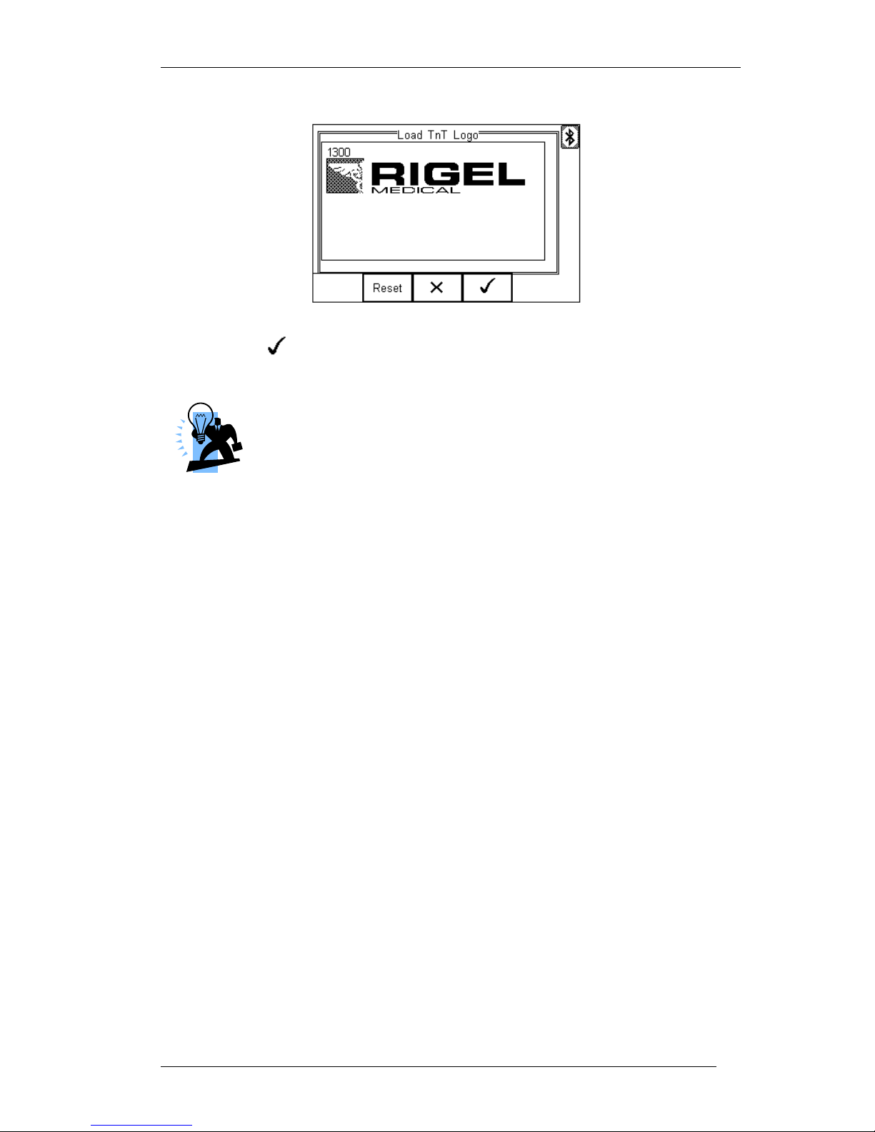
Rigel 288 plus Instruction Manual – Revision 1.1 - 93 -
Press the button (F4) to save the logo. The logo is now available for
printing using the Seaward Test ’nTag printer.
The file transfer can be made using any suitable PC application such
as the Seaward Bluetooth Downloader (data transfer.exe) or
Hyperterminal.
Page 95
Rigel 288 plus Instruction Manual – Revision 1.1 - 94 -
9. About
This screen provides details on the Rigel 288 plus’s;
Firmware version
Serial Number
Blue Tooth ID
Ensure you have this information available when contacting Rigel Medical for Technical
Support or Service. See chapter 9 for more information on Service and Calibration
Procedures.
Page 96

Rigel 288 plus Instruction Manual – Revision 1.1 - 95 -
10. Maintaining the Rigel 288 plus
10.1. Cleaning the Analyser
The Rigel 288 plus case can be cleaned with a damp cloth with, if necessary, a small
amount of mild detergent. Prevent excessive moisture around the socket panel or in the
lead storage area.
Do not allow liquid inside the Rigel 288 plus or near the sockets. Do not use abrasives,
solvents or alcohol.
If any liquid is spilt into the Rigel 288 plus case, the Analyser should be returned for
repair, stating the cause of the defect.
10.2. User Maintenance
The Rigel 288 plus is a rugged quality instrument. However, care should always be
taken when using, transporting and storing this type of equipment. Failure to treat the
product with care will reduce both the life of the instrument and its reliability.
If the Rigel 288 plus is subject to condensation, allow the Analyser to completely dry
before use.
Always check the Rigel 288 plus and all test leads for signs of damage and wear
before use.
Do not open the Rigel 288 plus under any circumstances.
Keep the instrument clean and dry.
Avoid testing in conditions of high electrostatic or electromagnetic fields.
Maintenance should only be performed by authorised personnel.
There are no user replaceable parts in the Rigel 288 plus.
The unit should be regularly calibrated (at least annually).
10.3. Return Instructions.
For repair or calibration return the instrument to:-
CalibrationHouse Contact details
CalibrationHouse Address details
Service, Calibration and Repair
Tel: +44 (0) 191 587 8739
Fax: +44 (0) 191 518 4666
Email: [email protected]
CalibrationHouse
11 Bracken Hill
South West Industrial Estate
Peterlee, County Durham
SR8 2SW, United Kingdom
Page 97

Rigel 288 plus Instruction Manual – Revision 1.1 - 96 -
Prior to returning your unit for service, please contact our service department to obtain a
Returns Number.
By obtaining a Returns Number, your service request can be booked in advance thus
reducing the down time of your equipment.
When asking for a Returns Number, please quote:
Instruments name and model
Serial number (see section 9)
Firmware version (see section 9)
Page 98

Rigel 288 plus Instruction Manual – Revision 1.1 - 97 -
10 Technical Specifications
Earth Continuity
Pre-pulse
65-25A peak current,
(0.1 to 0.8 Ω respectively)
Pulse shape
exponential decay
Decay time
200 – 550µs to 5% of peak current
(0.1 to 0.8 Ω respectively)
Method 2 wire technique
using 'zero' lead function.
Test Current
>+200mA -200mA DC into 2 ohms
Max Test Voltage
4-24V rms o/c (6V for IEC 60601 tests)
Measuring Range (low range)
0.001 – 0.999 ohms @ 0.001 ohms resolution
Measuring Range (mid range)
1.00 – 9.99 ohms /@ 0.01 ohms resolution
Measuring Range (high range)
10.0 – 19.9 ohms @ 0.1 ohms resolution
Accuracy
± 3% of reading + 10 m ohms
Insulation Resistance
Measurement
EUT to Earth / Ground, EUT to AP, AP to Ground
Voltage
50, 100, 250 & 500 V DC @1mA.
Range (low range) @ 50V DC
0.01Mohms - 10Mohms
Range (low range) @ Above 50V DC
0.01Mohms - 20Mohms
Accuracy (low range)
± 5% of reading + 2 counts
Range (high range) @ 500V DC
20Mohms – 100Mohms
Range (high range) @ 250V DC
20Mohms – 50Mohms
Accuracy (high range)
±10% +2 counts
Resolution
0.01Mohms
Direct Leakage Measurement
Measuring Range
4μA to 9999μA
Accuracy
± 5% or reading +2 counts
Mains on A.P. voltage
F-type only @ 110% of mains
Measuring Device
As per IEC 60601-1 requirements
Measurement Type
Separate AC & DC for Patient (-Auxiliary) Leakage to IEC
60601, True RMS for all remaining Leakage tests
Page 99

Rigel 288 plus Instruction Manual – Revision 1.1 - 98 -
Differential Leakage Measurement
Measuring Range
75μA to 9999μA
Accuracy
±5% of reading + 5 counts
Measurement / display resolution
1μA
Measurement Type
True RMS
Measuring Device
frequency response characteristics to IEC 60601-1.
Alternative Leakage Measurements:
Test Voltage
250V at mains frequency
Test Current
3.5 mA current limited
Measurement Range
4μA to 9999μA
Measurement Resolution
1μA
Measurement Accuracy
±5% of reading + 2 counts
Measurement Type
True RMS
Measuring Device
As per IEC 60601-1
Power Measurement
Method
VA rating.
Range
0.1KVA – 4KVA
Accuracy
±10% + 2 counts
Mains Outlet Test
Input voltage range
0-300V AC
max current
16A
Measures
L – E, N – E
Accuracy
± 5% of reading + 2 counts
IEC Mains Lead Test
Test Duration
2s
Test
Continuity of all EB conductor, Insulation & Polarity
Page 100

Rigel 288 plus Instruction Manual – Revision 1.1 - 99 -
General
Mains power
230 VAC ±10%, 50Hz +/- 1Hz
120 VAC ±10%, 60Hz +/- 1Hz (USA model)
Battery
6 x 1.5V Alkaline AA
Weight
1.6 kg including batteries
Size (L x W x D)
270 x 110 x 75 mm / 10.5 x 4 x 3”
Operating conditions
0˚C - 40˚C, 0-90% RH - NC
Storage environment
-15˚C - +60˚C
Environmental Protection
IP 40
 Loading...