


R41Z-EVAL User Guide

R41Z-EVAL User Guide Rev 2.0
1
Contents
Table of Contents
Contents ............................................................................................................................................... 1
Introduction ......................................................................................................................................... 2
2.1 Key Features ................................................................................................................................. 2
Hardware Kit ......................................................................................................................................... 2
Development Tools .............................................................................................................................. 1
Application Firmware Development ................................................................................................... 2
5.1 Set Up Toolchain .......................................................................................................................... 2
5.2 Try an Example ............................................................................................................................. 3
Hardware Description .......................................................................................................................... 9
6.1 Power .......................................................................................................................................... 10
6.1.1 R41Z Power Modes ............................................................................................................... 11
6.1.2 Power Configuration Switch ................................................................................................ 12
6.1.3 DC-DC Mode Selection .......................................................................................................... 13
6.1.4 Measuring Power Consumption ........................................................................................... 14
6.2 Debug Interface .......................................................................................................................... 15
6.2.1 OpenSDA Interface ............................................................................................................... 15
6.2.2 Reset Button ......................................................................................................................... 15
6.2.3 External Debug Header ........................................................................................................ 15
6.3 Peripherals ................................................................................................................................. 17
6.3.1 Expansion Headers ............................................................................................................... 17
6.3.2 IR LED Provision .................................................................................................................... 18
6.3.3 User LEDs .............................................................................................................................. 18
6.3.4 Thermistor ............................................................................................................................ 19
6.3.5 User Buttons ......................................................................................................................... 19
6.3.6 SPI Flash ................................................................................................................................ 20
6.3.7 I2C Acceleration/Magnetometer Sensor .............................................................................. 21
6.4 R41Z Module ............................................................................................................................... 22
6.4.1 32.768kHz Oscillator ............................................................................................................. 22
Related Documents ............................................................................................................................ 23
Life Support and other High-Risk Use Warning ................................................................................. 23
Environmental .................................................................................................................................... 23
9.1 RoHS ........................................................................................................................................... 23
9.2 REACH ......................................................................................................................................... 23
9.3 California Proposition 65 (P65) .................................................................................................. 23
Contact Information ........................................................................................................................... 24
List of Tables ....................................................................................................................................... 25
List of Figures ..................................................................................................................................... 25
Document History .............................................................................................................................. 26

R41Z-EVAL User Guide Rev 2.0
2
Introduction
The R41Z Evaluation Kit from Rigado allows for stand-alone use of the R41Z Module featuring the NXP
MKW41Z RF System on Chip (SoC).
This guide provides setup instructions for starting development and describes the hardware
functionality of the R41Z Evaluation Kit that can facilitate development of your project.
The R41Z Evaluation Kit provides a great starting point for almost any Bluetooth Smart (4.2 Low
Energy) or Thread project. All the features of the R41Z module are easily accessed from the evaluation
board. A simple USB connection provides power and OpenSDA V2.1 based debugging. Four user
buttons (two conventional and two capacitive) are available, as well as an RGB LED, reset button,
combination acceleration/magnetometer sensor, and an external 4Mbit flash module. Arduino form
factor headers provide access to 16 GPIO and 6 analog inputs. This allows for easy use of the Rigado
R41Z Shields, as well as many existing Arduino shields. Current sense resistors allow for measuring
current into the R41Z module and into the shield.
2.1 Key Features
• R41Z Thread + Bluetooth Module
• On-board programming and debug (OpenSDA
v2.1)
• Virtual COM port over USB
• Pin-for-pin compatible with projects created
for the NXP FRDM-KW41Z board
• Buttons and LEDs for user interaction
• 3-axis combination accelerometer and
magnetometer, I2C interface
• 4Mbit Flash, SPI interface
• Provision for IR LED
• 32.768kHz crystal
• CR2032 battery holder
• Supports all DC-DC modes of the R41Z
module
• Adjustable output regulator simplifies
development
Hardware Kit
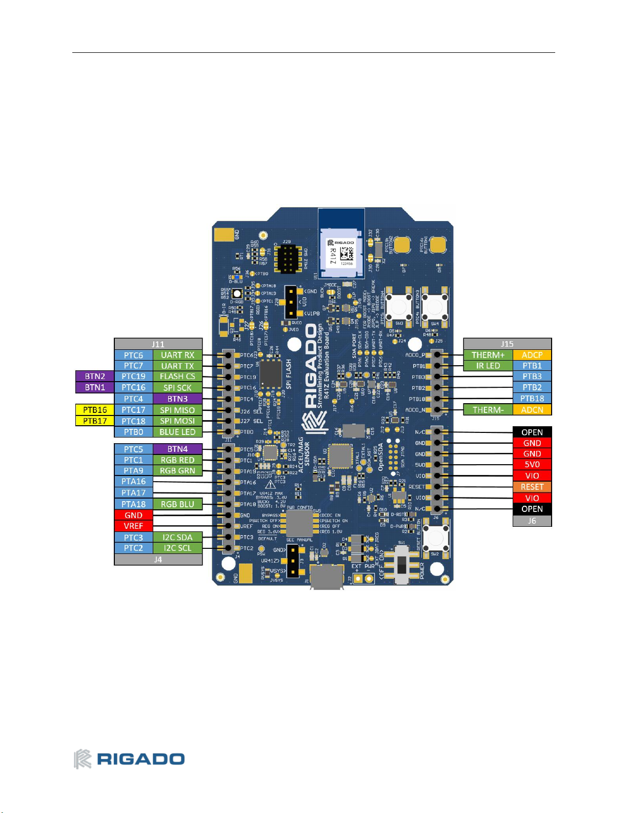
Figure 1 – R41Z Evaluation Board (Top View)
R41Z-EVAL:
• R41Z Evaluation Board
• Micro-USB Cable
• Quick start guide

R41Z-EVAL User Guide Rev 2.0
1
Development Tools
The tools listed below will aid in development with the R41Z modules. Not all tools will be required
depending on which software suite is used.
Tool
Description
MCUXpresso IDE
An easy-to-use integrated development environment (IDE) for
creating, building, debugging, and optimizing your application.
MCUXpresso SDK
An open source software development kit (SDK) built specifically
for your processor and evaluation board selections.
MCUXpresso Config Tools
A comprehensive suite of system configuration tools, including
pins, clocks, Peripherals, and more.
NXP IoT Toolbox
IoT Toolbox is an all-in-one application capable of demonstrating
NXP’s Bluetooth® LE, Zigbee and Thread capabilities through the
implementation of Bluetooth® LE and custom proprietary
profiles, allowing the interaction with different smartphones.
Table 1 – Useful Tools

R41Z-EVAL User Guide Rev 2.0
2
Application Firmware Development
This section walks through how to set up and program the R41Z Evaluation Kit with an example
application.
NOTE: This process will erase any preloaded firmware provided by Rigado including bootloader and
demonstration firmware, if provided. To access any firmware or demo applications that may be
preloaded on the R41Z evaluation kit, please contact Rigado (modules@rigado.com)
5.1 Set Up Toolchain
The MCUXpresso tools are used for application development for the R41Z. All examples within the SDK
for the NXP FRDM-KW41Z will function, unchanged, on the R41Z-EVAL.
1. Establish an account and login to the NXP website:
a. https://www.nxp.com/webapp-signup/register for a new account
b. https://www.nxp.com/security/login to login to an existing account
2. Download and install the NXP Semiconductors “IoT Toolbox” app on an available iOS or
Android device. The app is available from the respective app stores. This app will be used to
connect to the R41Z-EVAL board loaded with the SDK examples.
3. Download and install the MCUXpresso IDE on a PC. Windows, macOS and Linux are supported.
4. Download and install the MCUXpresso Config Tools on a PC. Windows, macOS and Linux are
supported.
5. Download the MCUXpresso SDK. Select the FRDM-KW41Z Development Board. This download
will be a zip file.
a. The SDK documentation is available in the “docs” directory within the zip file.
6. Open the MCUXpresso IDE.
7. Install the MCUXpresso SDK into the IDE by dragging the downloaded zip file to the lower right
pane:
8. Connect your R41Z Evaluation Board to your host computer using the supplied USB cable. The
board should show up as a mass storage device and a new virtual COM port will also appear.
Figure 2 – SDK installation
R41Z-EVAL User Guide Rev 2.0
3
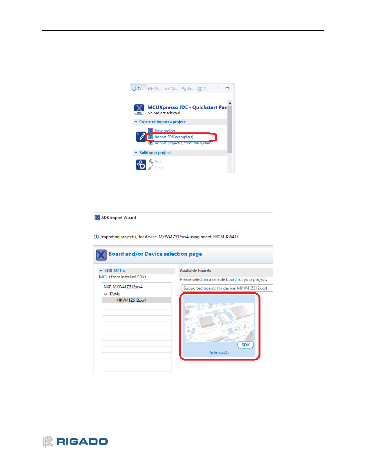
5.2 Try an Example
Import and run an example from the SDK.
1. In the lower left pane, click on “Import SDK example(s)…”
2. Click on the “frdmkw41z” under “Available boards”, then click “Next”
Figure 3 – Import example
Figure 4 – Select board
R41Z-EVAL User Guide Rev 2.0
4
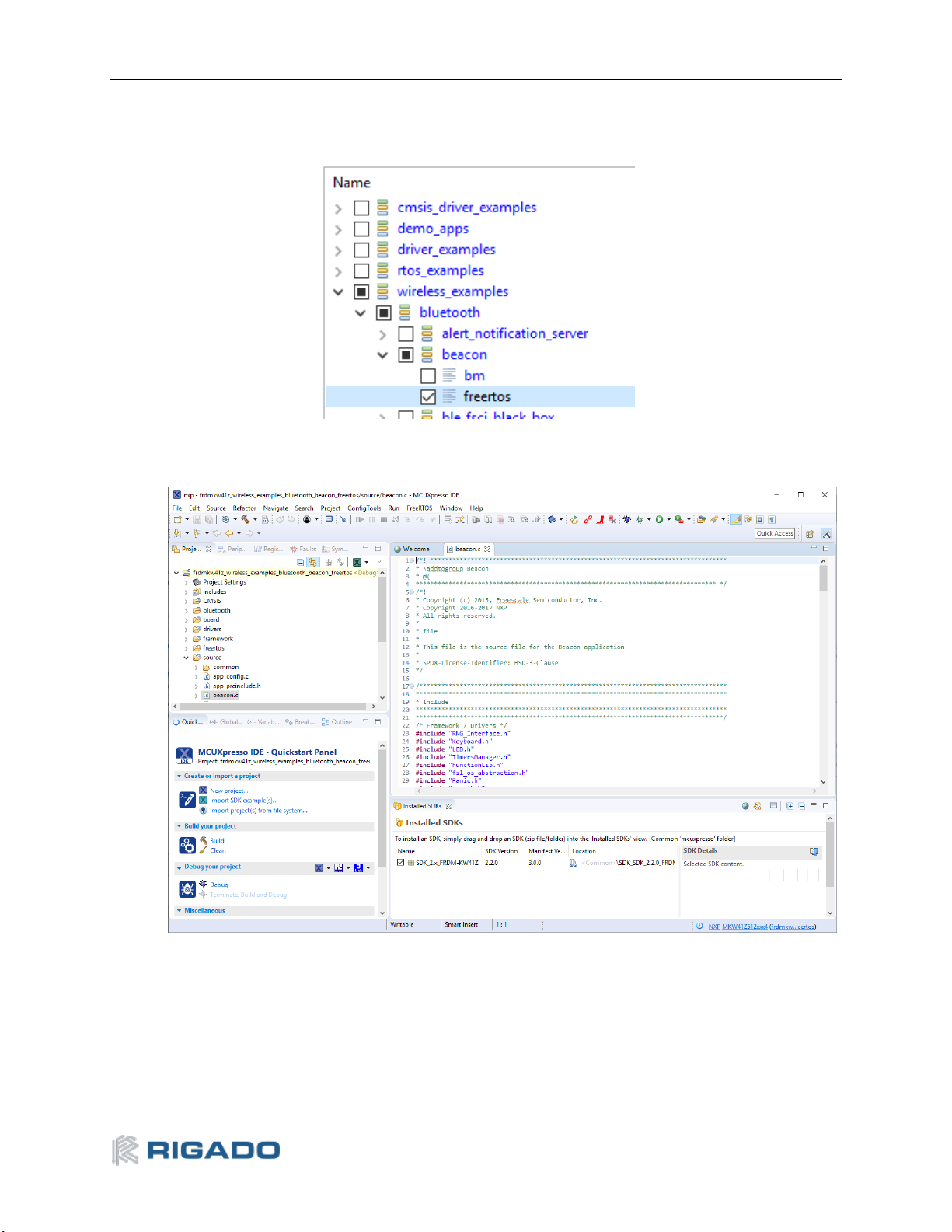
3. On the next screen, select the example, then click Finish. In this case, we’ll use the “Bluetooth
Beacon”.
4. Application source code is in the project tree under the “source” directory:
Figure 6 – Example source code
Figure 5 – Select Bluetooth Beacon example

R41Z-EVAL User Guide Rev 2.0
5
5. Click the “hammer” icon to build the project:
6. Click the “bug” icon to start debugging:
7. Select the “J-Link OpenSDA” debug probe and click OK:
Figure 9 – Debug probe selection
Figure 7 – Build the example
Figure 8 – Start debugging
R41Z-EVAL User Guide Rev 2.0
6
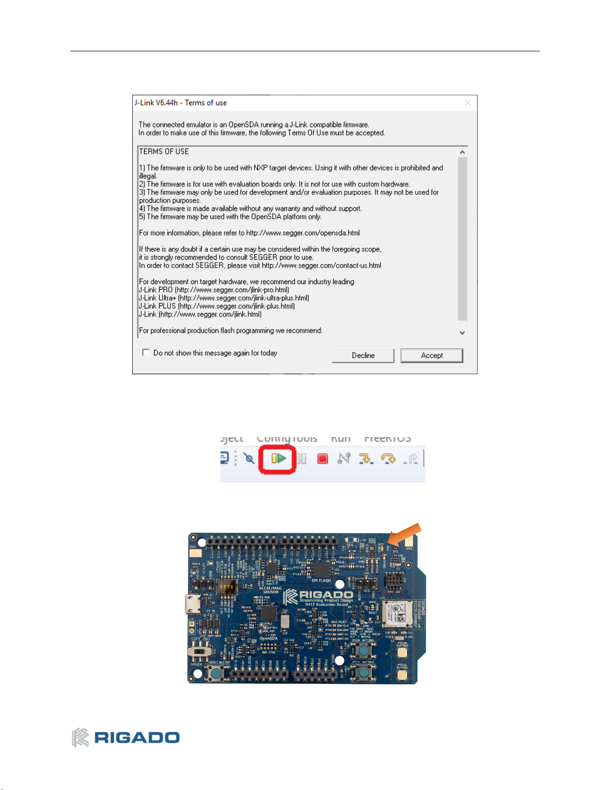
8. Accept the OpenSDA terms of use:
Figure 10 – OpenSDA Terms of Use
9. Click the “Play” icon to run the application:
Figure 11 – Run the example
10. Observe the blue LED flashing on the R41Z-EVAL board:
Figure 12 – Flashing LED

R41Z-EVAL User Guide Rev 2.0
7
11. Open the NXP IoT Toolbox mobile app on your mobile device, and tap the “Beacons” icon:
Figure 13 – NXP IoT Toolbox mobile app
12. Observe the beacon RSSI increase as you move the mobile device closer to the R41Z-EVAL.
Figure 14 – Advertising Beacon

R41Z-EVAL User Guide Rev 2.0
8
13. The advertising data for A, B, and C values may be changed in the file “app_config.c”:
/* Advertising Data */
static const uint8_t adData0[1] = {
(gapAdTypeFlags_t)(gLeGeneralDiscoverableMode_c | gBrEdrNotSupported_c) };
static uint8_t adData1[26] = {
/* Company Identifier*/
mAdvCompanyId,
/* Beacon Identifier */
mBeaconId,
/* UUID */
mUuid,
/* A */
0x00, 0x00,
/* B */
0x00, 0x00,
/* C */
0x00, 0x00,
/* RSSI at 1m */
0x1E};
R41Z-EVAL User Guide Rev 2.0
9
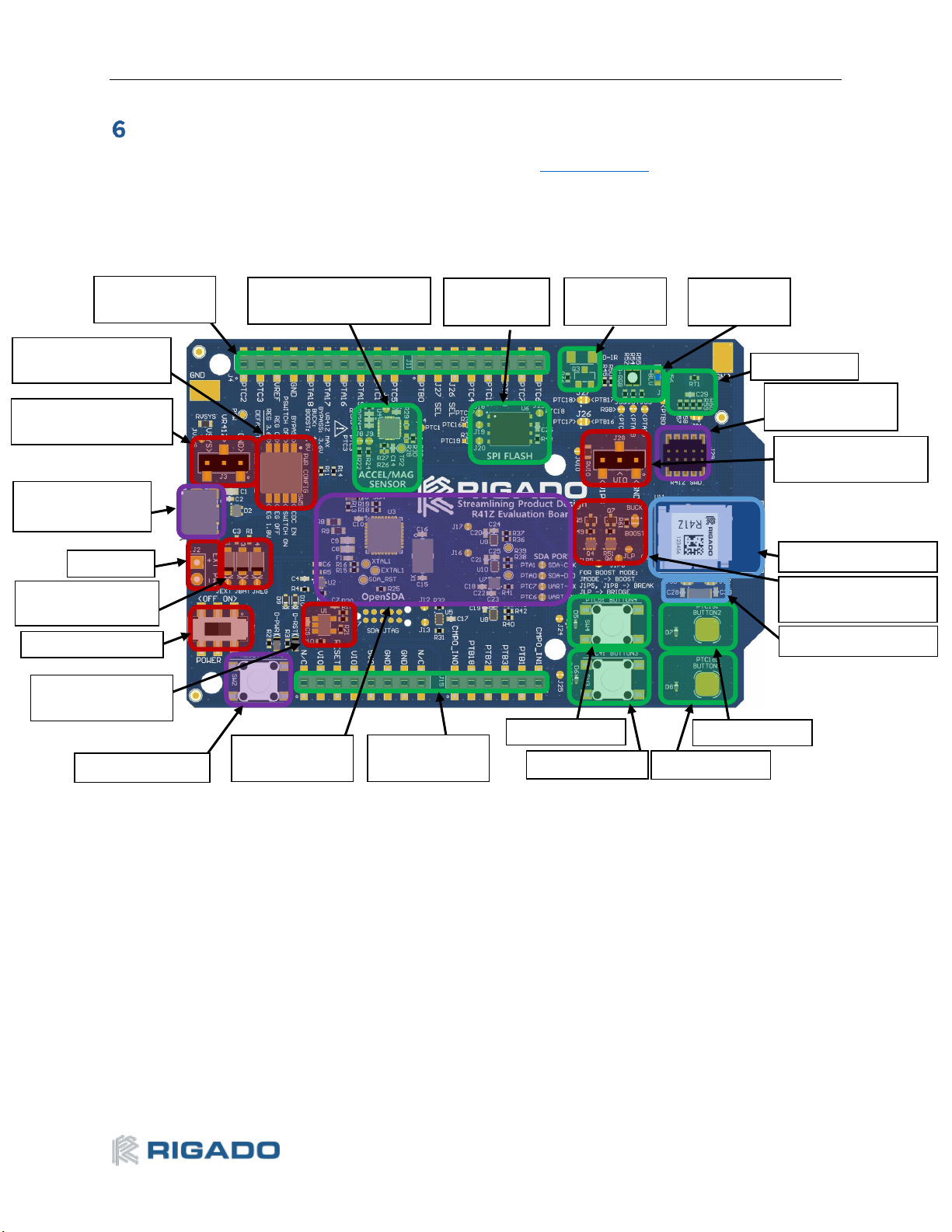
Hardware Description
Design files for the R41Z Evaluation Kit may be found on the Rigado website.
Figure 15 – Evaluation Board Layout
Accelerometer /
Magnetometer Sensor
SPI Flash
Module
IR-LED
Provision
RGB and
Blue User
Thermistor
External Debugger
Header
Peripheral Current
Measurement Header
R41Z Module
Power Configuration
Jumpers
User Button2
User Button5
User Button3
User Button4
Breakout
Headers
OpenSDA Debug
Interface
Reset Button
USB Power
Regulator
Power Switch
Power Protection
Diodes
Ext. Power
Micro-USB for
Power and Debug
Board Current
Measurement Header
Power Configuration
Switch
Breakout
Headers
32.768kHz Oscillator
R41Z-EVAL User Guide Rev 2.0
10
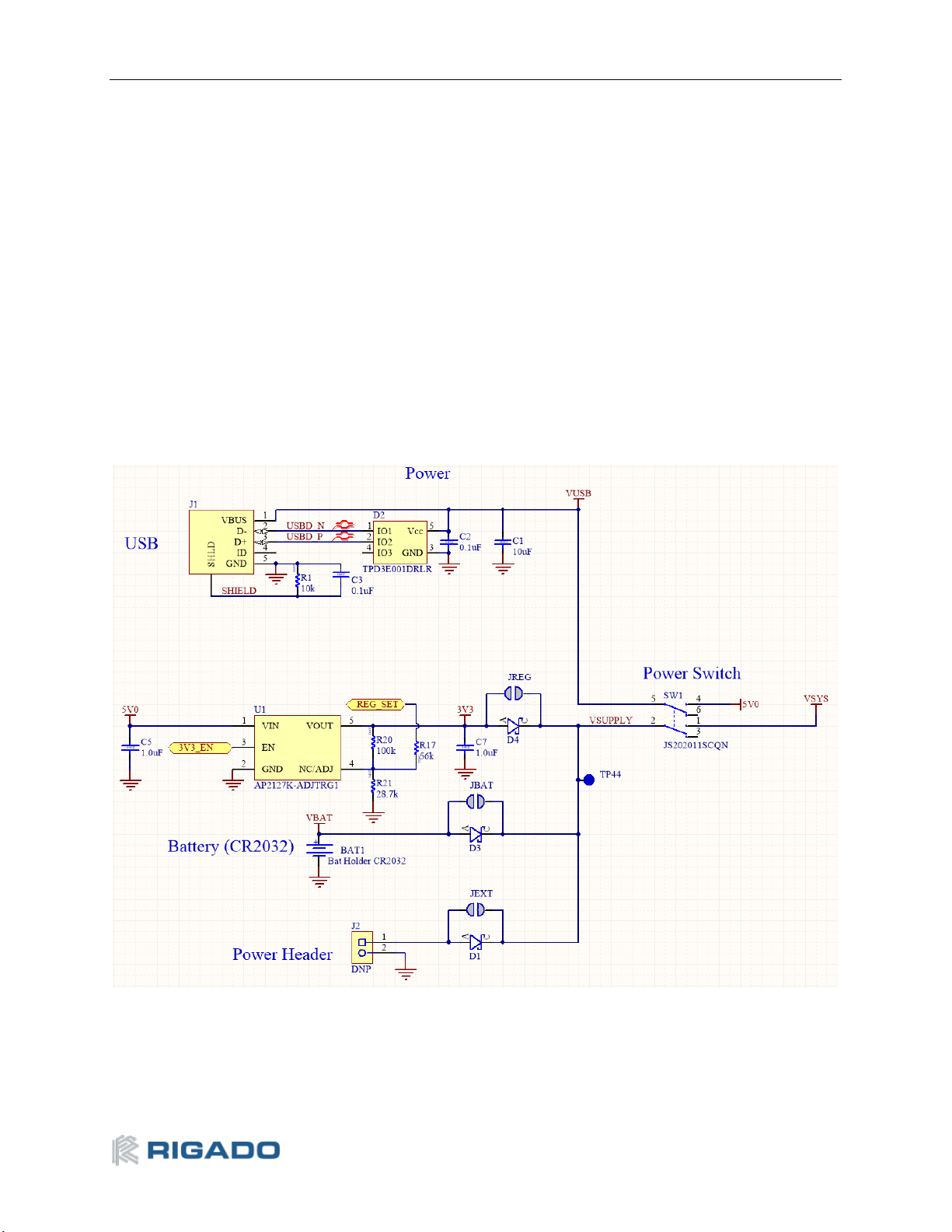
6.1 Power
The R41Z Evaluation Board has three possible power sources: USB, a CR2032 coil cell, and a 0.1”
through-hole connector. These sources are OR’d together with protection diodes to prevent reverse
voltage to any supply. These allows for more than one source to be connected at a time. For example,
a coil cell battery may remain connected to the board while the board is being debugged with the USB
source connected. However, since the diodes do cause approximately a 0.3V drop in source voltage,
there is the option to bypass the diodes via solder jumpers. Care should be taken to not damage the
supplies or Evaluation board when the protection is by-passed.
If necessary, the LDO regulator can be disabled in order to allow for USB based debugging while
powering the R41Z from either an external source or a coil cell. Since the R41Z can accept a wide
range of power options, the LDO regulator can be adjusted to simulate some sources. For details on
these options, see Power Configuration Switch section later in this document.
Figure 16 – Schematic: Power Supply

R41Z-EVAL User Guide Rev 2.0
11
6.1.1 R41Z Power Modes
The Rigado R41Z module contains a DC-DC converter that allows it to operate in a variety of power
environments. The R41Z Evaluation board supports all these operating modes, which are summarized
below:
R41Z DC-DC Converter Modes
Mode
Input
Voltage
Output
Voltage
Usage Notes
Bypass
1.71V – 3.6V
N/A
DC-DC Converter is bypassed: Input voltage directly
supplies all internal module power rails. Suitable for
larger or non-battery powered applications that have
steady, regulated 3.3V or 1.8V power rails that power
multiple devices. Since the DC-DC converter is bypassed
in this mode, the R41Z cannot provide regulated power
to other devices.
Buck
1.8V – 4.2V
1.8V – 3.0V
1
DC-DC Converter operates in buck mode. Internal power
rails are sourced and regulated by the R41Z module. An
externally available power rail (V1P8) allows the R41Z to
supply regulated power to other peripheral devices.
Suitable for small applications powered directly from a
lithium ion battery 2. If total power consumption is low,
the R41Z module can provide a regulated power rail to
supply other devices.
Boost
0.9V – 1.8V
1.8V – 3.0V
1
DC-DC Converter operates if boost mode. Internal power
rails are sourced and regulated by the R41Z module. An
externally available power rail (V1P8) allows the R41Z to
supply regulated power to other peripheral devices.
Suitable for small applications powered directly from a
low voltage battery 2 (For example, alkaline or NiMH). If
total power consumption is low, the R41Z module can
provide a regulated power rail to supply other devices.
Note 1: Output voltage is user adjustable in Buck and Boost mode. Defaults to 1.8V at Power On
Reset. In Buck mode, output voltage cannot be greater than input voltage.
Note 2: The R41Z does not include automatic battery management. Applications powered from
batteries must include battery management and protection features implemented with additional
hardware and/or software.
Table 2 – R41Z Power Modes
R41Z-EVAL User Guide Rev 2.0
12
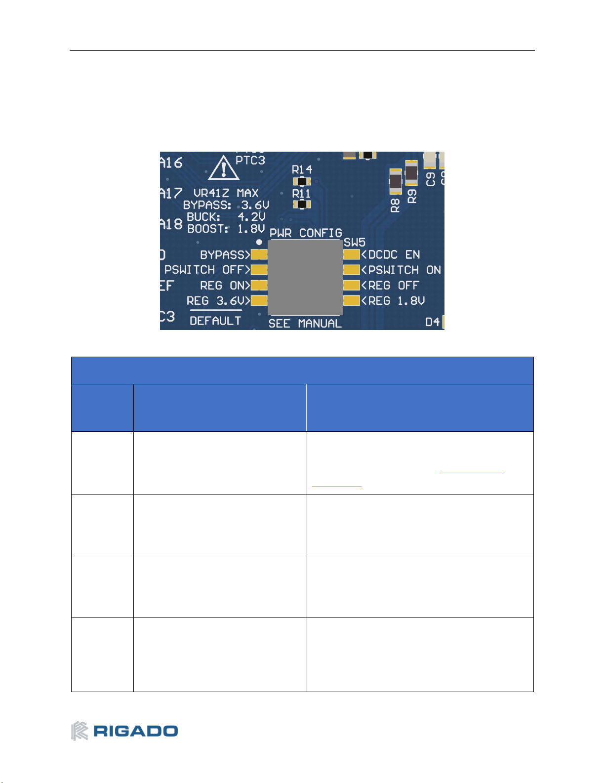
6.1.2 Power Configuration Switch
The power configuration switch allows easy and quick adjustment of most power settings on the R41Z
Evaluation Board.
Figure 17 – Power Configuration Switch
Power Configuration Switch
SW
Position
Default
Option
1
Bypass Power Mode
DC-DC Power Mode. Buck Mode by default;
Boost mode selectable with Power
Configuration Jumpers. See DC-DC Mode
Selection.
2
PSWITCH OFF. When in Buck Mode,
the DC-DC converter will not start
when power is applied. Use this
option when using Bypass Mode.
PSWITCH ON. When in Buck mode, the DC-DC
Converter will automatically start when power
is applied. Use this option when using Boost
Mode.
3
Regulator On. When USB is
connected, the LDO regulator will
supply power to the Evaluation
Board.
Regulator Off. When USB is connected, the LDO
regulator will not supply power.
4
Regulator 3.6V. When USB is
connected, the LDO regulator will
output 3.6V. With the reverse
protection diode, 3.3V is applied to
the R41Z.
Regulator 1.8V. When USB is connected, the
LDO regulator will output 1.8V. With the reverse
protection diode, 1.5V is applied to the R41Z.
Useful for using Boost mode.
Table 3 – Power Configuration Switch Options

R41Z-EVAL User Guide Rev 2.0
13
6.1.3 DC-DC Mode Selection
For details regarding the electrical connections required to implement each power mode, please
reference the R41Z Evaluation Board Schematic and R41Z Module Data Sheet. These documents are
available online at the Rigado website.
Switching between Bypass Mode and Buck mode can easily be accomplished using the Power
Configuration Switch. To use Boost Mode there are other changes that must be made via the Power
Configuration Jumpers, summarized below.
Figure 18 – Power Configuration Jumpers (Default)
The 4 jumpers used to switch between Buck and Boost DC-DC modes are labeled JMODE, JLP, J1P5,
and J1P8. See the figures below for how to set these jumpers along with the correct Power
Configuration Switch positions.
DC-DC Mode Selection
Mode
PWR Config SW
JMODE
JLP
J1P5
J1P8
Bypass
Pos. 1: Bypass
(Default)
Pos. 2: OFF (Default)
Pos. 4: REG 3.6V
Buck
(Default)
Open
(Default)
Closed
(Default)
Closed
(Default)
Buck
Pos. 1: DC-DC EN
Pos. 2: Off or On*
Pos. 4: REG 3.6V
Buck
(Default)
Open
(Default)
Closed
(Default)
Closed
(Default)
Boost
Pos. 1: DC-DC EN
Pos. 2: On
Pos. 4: REG 1.8V
Boost
Closed
Open
Open
*Note: See Error! Reference source not found. for using PSWITCH in Buck mode
Table 4 – DC-DC Mode Selection

R41Z-EVAL User Guide Rev 2.0
14
Figure 19 below shows the Power Configuration Jumpers in Boost mode with solder jumpers across
JMODE and JLP. JMODE features a white dot, highlighted by a red circle below, to indicate the default
bridged connection. Do not bridge all three pads of jumper JMODE.
Figure 19 – Power Configuration Jumpers (Boost Mode)
6.1.4 Measuring Power Consumption
When operating the R41Z Evaluation Board in DC-DC power mode, the board power source (LDO
regulator, coin cell, or external power) directly powers both the R41Z module but also all onboard
peripheral devices and provides expansion shield power. However, when operating in either Buck or
Boost DC-DC Mode, the R41Z module supplies regulated power to the peripheral devices and shield.
This makes it difficult to directly measure the power consumption of just the R41Z module. The
Evaluation Board features two current measurement headers that allow direct measurement of total
current and peripheral current. The current consumption of only the R41Z Module can be indirectly
measured by subtracting the peripheral current from the system current reading.
Figure 20 – Schematic: Current Measurement Headers

R41Z-EVAL User Guide Rev 2.0
15
6.2 Debug Interface
The R41Z Evaluation Board features an OpenSDA 2.1 interface which includes a SWD connection and
virtual COM port for easy programming and debugging of the R41Z module.
6.2.1 OpenSDA Interface
The OpenSDA hardware is separated from the R41Z target by a set of level shifters to ensure that
debugging can be done regardless of the DC-DC mode used. The interface will operate in a similar
manner to other evaluation boards that use OpenSDA. When connected to a host computer, the
Evaluation board will appear as a mass storage device named “FRDM-KW41Z”. Binary files can be
directly copied to this drive to load them to the R41Z target.
The R41Z Evaluation Board ships with a Segger debug application loaded but other OpenSDA 2.1
applications may be used. To load a new OpenSDA application, apply power to the board while
holding the reset button. The Evaluation Board will appear as mass storage device named
“Maintenance” onto which the OpenSDA application binary can be copied.
6.2.2 Reset Button
The reset button is primarily meant to be used to reset the R41Z module. It is also used to put the
OpenSDA interface into “Maintenance” mode to allow for different Debug Applications to be loaded.
The reset pin on the R41Z module and the OpenSDA I/O are both connected to the reset button and
isolated from each other by diodes. Unlike the standard OpenSDA implementation, a header is not
needed to select which device the reset button is connected to.
When power is initially applied, the OpenSDA interface momentarily ignores any reset signal asserted
by the R41Z in order to sample the state of the reset button. This is done by setting the reset line level
shifter between the OpenSDA interface and the R41Z to a high impedance state.
Figure 21 – Schematic: Reset Button
6.2.3 External Debug Header

R41Z-EVAL User Guide Rev 2.0
16
In addition to the onboard OpenSDA interface, the R41Z Evaluation Board supports the use of external
debuggers. A standard 10-pin SWD/JTAG header is provided with the following pinout to the target
R41Z module:
0
Pin
Usage
1
V1P8 (R41Z I/O
voltage)
2
SWDIO
3
GND
4
SWCLK
5
GND
6
N/C 7 N/C 8 N/C
9
GND
10
RESET_n
Table 5 – External Debugger Header Pinout
R41Z-EVAL User Guide Rev 2.0
17
6.3 Peripherals
The R41Z Evaluation Board includes a set of onboard peripherals and a set of Arduino style headers
that allow for additional peripherals of the user’s choice to be added in the form of expansion shields.
These headers share I/O connections to the R41Z module with the existing onboard peripherals. If an
on-board peripheral will interfere with the operation of a shield, jumpers can be used to disconnect
the on-board device.
6.3.1 Expansion Headers
Figure 22 – Expansion Header Pinout

R41Z-EVAL User Guide Rev 2.0
18
6.3.2 IR LED Provision
An unpopulated position for an IR LED and driver transistor are provided on the Evaluation board. If IR
is part the application under development, these parts can be populated by the end user. The IR LED
footprint is intended for a right angle, SMT 3317 package. The drive transistor footprint is intended for
an SOT-23 NPN BJT. Resistor R45 is not provided on the board to avoid pulling down PTB1.
Figure 23 – Schematic: IR LED
6.3.3 User LEDs
The R41Z Evaluation Board features an RGB LED and a separate blue LED. Since the GPIO used are
shared with the expansion header, solder jumpers are provided to disconnect the LEDs if required.
Since the LEDs are powered from the peripheral power bus “VIO”, they will be powered directly by the
R41Z module when it is operating in either Buck or Boost DC-DC mode. This may affect LED visibility at
low output voltages.
Figure 24 – Schematic: User LEDs

R41Z-EVAL User Guide Rev 2.0
19
6.3.4 Thermistor
A thermistor circuit is provided to demonstrate the analog capabilities of the R41Z module and to aid
development of applications requiring temperature measurement.
Figure 25 – Schematic: Thermistor and ADC Mode Selection
6.3.5 User Buttons
Two mechanical buttons (SW3, SW4) and two capacitive touch buttons (SW2, SW5) are provided on
the Evaluation Board. The Capacitive touch buttons enable easy development of applications that
make use of the R41Z’s Touch Sense Input (TSI) module.
Figure 26 – Schematic: User Buttons

R41Z-EVAL User Guide Rev 2.0
20
6.3.6 SPI Flash
To assist development of applications requiring external storage, a 4Mbit flash module is provided
(Adesto Tech. AT45DB041E-MHN2B-T). The flash uses an SPI interface with signals shared with the
expansion headers. When using multiple Chip Select (CS) signals, this allows the same SPI bus to be
used with both the Flash module and one or more SPI devices on an expansion shield. However, some
signals are also shared with the TSI user buttons.
SPI Flash
Signal
R41Z I/O
SPI CLK
PTC16
SPI MOSI
PTC17
SPI MISO
PTC18
Flash
CS_n
PTC19
Table 6 – SPI Port Signals
Figure 27 – Schematic: SPI Flash

R41Z-EVAL User Guide Rev 2.0
21
6.3.7 I
2
C Acceleration/Magnetometer Sensor
For development of applications that require orientation and movement tracking, a combined
accelerometer and magnetometer is provided (NXP FXOS8700CQR1). The sensor can support either
SPI or I2C interfaces but is used exclusively with the I2C interface on the R41Z Evaluation Board. When
in I2C mode, the address of the sensor can be set using external pull-up and pull-down resistors. The
signals used for the I2C bus are shared with the expansion headers. Because of the addressed nature of
I2C it is possible to use this same bus to connect to additional devices on a shield.
Combo Sensor Address
Address
SA1
SA0
0x1C
1
0
0x1D
0
1
0x1E
0
0
0x1F
(Default)
1
1
Table 7 – Combo Sensor Addresses
I2C Sensor
Signal
R41Z I/O
Interrupt
PTC1
SCLK
PTC2
SDA
PTC3
Table 8 – I2C Sensor Signals
Figure 28 – Schematic: I2C Combo Sensor

R41Z-EVAL User Guide Rev 2.0
22
6.4 R41Z Module
For details on the R41Z module, see the Rigado R41Z Data Sheet (rigado.com/r41z). The R41Z
module is an industry leading Bluetooth and Thread pre-certified (pending) module with a wide range
of potential applications.
6.4.1 32.768kHz Oscillator
For RTC and to maintain high accuracy Bluetooth time keeping in low power modes, an external
32.768kHz crystal oscillator is provided. Some applications may not require this external oscillator in
which case a set of jumpers can be used to connect these I/O to the expansion headers. The R41Z
module features programmable capacitors which can be used in place of external capacitors.
However, external capacitors are provided on the R41Z Evaluation Board to simplify firmware
development.
Figure 29 – Schematic: 32kHz Oscillator

R41Z-EVAL User Guide Rev 2.0
23
Related Documents
Rigado Documents:
• R41Z Module Product Brief
• R41Z Module Data Sheet
• Evaluation Kit Regulator Information
NXP Documents:
• KW41Z Fact Sheet
• NXP BLE Mobile Toolbox
• KW41Z Data Sheet
• KW41Z Reference Manual
• KW41Z Errata
Life Support and other High-Risk Use Warning
This product is not designed nor intended for use in a life support device or system, nor for use in
other fault-intolerant, hazardous or other environments requiring fail-safe performance, such as any
application in which the failure or malfunction of the product could lead directly or indirectly to
death, bodily injury, or physical or property damage (collectively, “High-Risk Environments”). RIGADO
EXPRESSLY DISCLAIMS ANY EXPRESS OR IMPLIED WARRANTY OF FITNESS FOR USE IN HIGH-RISK
ENVIRONMENTS. The customer using this product in a High-Risk Environment agrees to indemnify and
defend Rigado from and against any claims and damages arising out of such use.
Environmental
9.1 RoHS
Rigado’s modules are in compliance with Directive 2011/65/EU, 2015/863/EU of the European
Parliament and the Council on the restriction of the use of certain hazardous substances in electrical
and electronic equipment. The declaration may be found here: https://go.rigado.com/RoHS-Modules
9.2 REACH
Rigado’s modules listed below do not contain the 191 SVHC (Substance of Very High Concern), as
defined by Directive EC/1907/2006 Article according to REACH Annex XVII. The compliance statement
may be found here: https://go.rigado.com/REACH-Modules
9.3 California Proposition 65 (P65)
This product can expose you to Nickel (metallic), which is known to the State of California to cause
cancer. For more information go to www.P65Warnings.ca.gov.

R41Z-EVAL User Guide Rev 2.0
24
Contact Information
Headquarters
Rigado Inc.
3950 Fairview Industrial Drive SE, Suite 100
Salem, Oregon 97302
Portland
Rigado Inc.
101 SW Main Street, Suite 2000
Portland, Oregon 97204
Tel: +1 971 208 9870
Fax: +1 971 208 9869
Sales: https://www.rigado.com/contact/
modules@rigado.com
Support: https://rigado.zendesk.com/hc
support@rigado.com

R41Z-EVAL User Guide Rev 2.0
25
List of Tables
Table 1 – Useful Tools .................................................................................................................................. 1
Table 2 – R41Z Power Modes ..................................................................................................................... 11
Table 3 – Power Configuration Switch Options ........................................................................................ 12
Table 4 – DC-DC Mode Selection ................................................................................................................ 13
Table 5 – External Debugger Header Pinout ............................................................................................. 16
Table 6 – SPI Port Signals ........................................................................................................................... 20
Table 7 – Combo Sensor Addresses ........................................................................................................... 21
Table 8 – I2C Sensor Signals ...................................................................................................................... 21
Table 9 – Document History ....................................................................................................................... 26
List of Figures
Figure 1 – R41Z Evaluation Board (Top View) ............................................................................................. 2
Figure 2 – SDK installation ........................................................................................................................... 2
Figure 3 – Import example ........................................................................................................................... 3
Figure 4 – Select board ................................................................................................................................. 3
Figure 5 – Select Bluetooth Beacon example .............................................................................................. 4
Figure 6 – Example source code .................................................................................................................. 4
Figure 7 – Build the example ........................................................................................................................ 5
Figure 8 – Start debugging ........................................................................................................................... 5
Figure 9 – Debug probe selection ................................................................................................................ 5
Figure 10 – OpenSDA Terms of Use ............................................................................................................. 6
Figure 11 – Run the example ........................................................................................................................ 6
Figure 12 – Flashing LED .............................................................................................................................. 6
Figure 13 – NXP IoT Toolbox mobile app ..................................................................................................... 7
Figure 14 – Advertising Beacon .................................................................................................................... 7
Figure 15 – Evaluation Board Layout ........................................................................................................... 9
Figure 16 – Schematic: Power Supply ....................................................................................................... 10
Figure 17 – Power Configuration Switch ................................................................................................... 12
Figure 18 – Power Configuration Jumpers (Default) ................................................................................ 13
Figure 19 – Power Configuration Jumpers (Boost Mode) ......................................................................... 14
Figure 20 – Schematic: Current Measurement Headers ........................................................................... 14
Figure 21 – Schematic: Reset Button ......................................................................................................... 15
Figure 22 – Expansion Header Pinout ........................................................................................................ 17
Figure 23 – Schematic: IR LED .................................................................................................................... 18
Figure 24 – Schematic: User LEDs .............................................................................................................. 18
Figure 25 – Schematic: Thermistor and ADC Mode Selection .................................................................. 19
Figure 26 – Schematic: User Buttons ......................................................................................................... 19
Figure 27 – Schematic: SPI Flash ............................................................................................................... 20
Figure 28 – Schematic: I2C Combo Sensor ................................................................................................ 21
Figure 29 – Schematic: 32kHz Oscillator ................................................................................................... 22

R41Z-EVAL User Guide Rev 2.0
26
Document History
Revision
Date
Changes / Notes
0.9
2016-11-09
Initial release
2.0
2019-05-09
Updated to new document format
Changed tools to MCUXpresso
Table 9 – Document History
 Loading...