

Operating Manual
RIFOX - Hans Richter GmbH Spezialarmaturen
Fon: +49 (0) 421 499 75 - 0
www.rifox.de
contact@rifox.de
Breite: 170
Höhe:8,15
RIFOka Thermo Controlled Capsule Trap, PN 40
1 Safety instructions
1.1 Proper use
Any improper use, intervention in the design and deviation from the design data automatically lead to termination of the
warranty. The thermally controlled condensate trap model 10210 is designed for the discharge of condensate from steam,
compressed air and pressure gas systems. Any other use is not permissible. The manufacturer is not liable for damage
resulting from any other use. The user or operator bears the risk in this case. This also applies analogously to incorrect assembly, startup, use and maintenance.
1.2 Warnings and symbols
■ Personal risk due to escaping operating medium because of pressure, temperature and weight. Failure to comply with
these warnings results in the risk of accidents.
■ Follow the instructions in this operating manual.
■ The operator must ensure that this operating manual and, if necessary, other relevant documents are available on site.
■ Only trained or instructed personnel may be assigned to handling this equipment.
■ Any mode of operation that may impair safety must be avoided.
2 General description and usage
Model: 10210
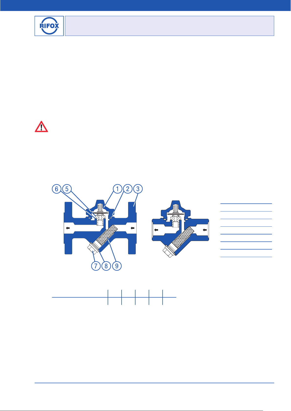
2.1 Design of the condensate trap
Picture 1: Model 10210 with Flanges Picture 2: Model 10210 with Threads
2.2 Operation limits of housing material (Design)
max. operating pressure (bar g) 40 37,1 33,4 27,6 23,8
max. operating temperature (°C) -10/20 100 200 300 400 *
* for ANSI max. 350°C
2.3. Function-limit of capsule: max. diff. Pressure PMO = 22 bar
Upper housing
1
Gasket
2
Flange part
3
4 Housing screws (not visible)
Valve unit
5
Gasket
6
Plug
7
Gasket
8
Strainer
9
Bertha-von-Suttner-Str. 9 D-28207 Bremen
Fax: +49 (0) 421 499 75 - 40
www.rifoxglobal.com
Page 1 of 3
sales@rifoxglobal.com
01/2017 -Di. Subject to modifications

Operating Manual
RIFOX - Hans Richter GmbH Spezialarmaturen
Fon: +49 (0) 421 499 75 - 0
www.rifox.de
contact@rifox.de
Breite: 170
Höhe:8,15
2.4 Discharge capacity
3000
2000
K
1000
800
600
500
400
Discharge capacity in kg/h
300
200
100
0,1
Pressure difference in bar (with reference to atmospheric pressure)
2.5 Function
A special liquid contained within the capsule evaporates or condenses due to changes in temperature. The operating temperature is only a few degrees below the boiling point of water. When the temperature rises, the liquid evaporates and the
valve closes. When the temperature drops, the liquid condenses and the valve opens.
Model 10210 is not applicable for media of fluid group1 !
3 Installation
■ Remove protective caps from inlet and outlet.
■ The flow direction is as indicated by the arrow.
■ The fitting position is vertical or horizontal.
■ To avoid down times, it is recommended that a shut-off valve be installed in front of and, if necessary, behind the conden-
sate trap.
H
The diagram shows the flow rate of hot condensate (H)
and cold condensate (K) in kg/h, with the standard capsule
type S, approx. 8 K undercooling.
0,2 0,3 0,4 0,6 0,8 10 222 3 4 61 8
Picture 3
4 Start-Up
The pressure build-up and heating-up of the housing should not take place abruptly. If leaks occur due to so-called settling
after the first startup, the housing screws (4) can be retightened taking into account the indicated torque on paragraph 6.2.
Retightening may only be carried out when the housing is depressurized and at most warm to the touch.
5 Observation and check
The function’s failure can be observed as steam entry.
With damming up of condensate upstream heating surfaces are flooded and the amount of heat is lowered.
Steam entry can be determined after the condensate outlet by the measuring device.
You can hear the way of working open/close of the working capsule or it can be determined by means of an ultrasonic measuring device. In case of constant currant sound a steam entry is probably.
6 Maintenance / Inspection
6.1 Opening the trap and dismantling the capsule
■ The condensate trap must be depressurized. Shut off the system securely in front of and behind the condensate trap.
■ The housing cool down until it is warm to the touch.
■ Loosen housing screws (4).
Page 2 of 3
-Di. Subject to modifications
Bertha-von-Suttner-Str. 9 D-28207 Bremen
01/2017
Fax: +49 (0) 421 499 75 - 40
www.rifoxglobal.com
sales@rifoxglobal.com
Operating Manual
RIFOX - Hans Richter GmbH Spezialarmaturen
Fon: +49 (0) 421 499 75 - 0
www.rifox.de
contact@rifox.de
Breite: 170
Höhe:8,15
■ Remove the upper housing (1).
■ Pull off the capsule from the valve unit (5).
6.2 Installing the capsule and assembly of the trap
■ Coat threads of valve unit (5) and thread of the housing screws (4) with a temperature-resistant lubricant (Rifox uses
installing paste M1-Molypaul).
■ Control whether the sealing surfaces of (1) and (3) are clean.
■ Insert new housing gasket (2) and/or gasket (8) if necessary.
■ Visual check the sealing surface of valve unit (5) on damage or transverse scoring (leakage).
■ Screw in the valve unit (5). Tightening torque 90 Nm.
■ Push the capsule with marking S carefully onto the valve unit (5)
■ Put on the upper housing (1) with compression spring.
■ Tighten housing screws (4) evenly. Tightening torque: 20 Nm
6.3 Draining and cleaning the strainer
■ The condensate trap must be depressurized. Shut off the system securely in front of and behind the condensate trap.
■ The housing cool down until it is warm to the touch.
■ Screw off the plug (7).
■ Take out the strainer (9) and clean it with compressed air.
■ Put in the stainer (9) and tighten the plug (7). Tightening torque 120 Nm.
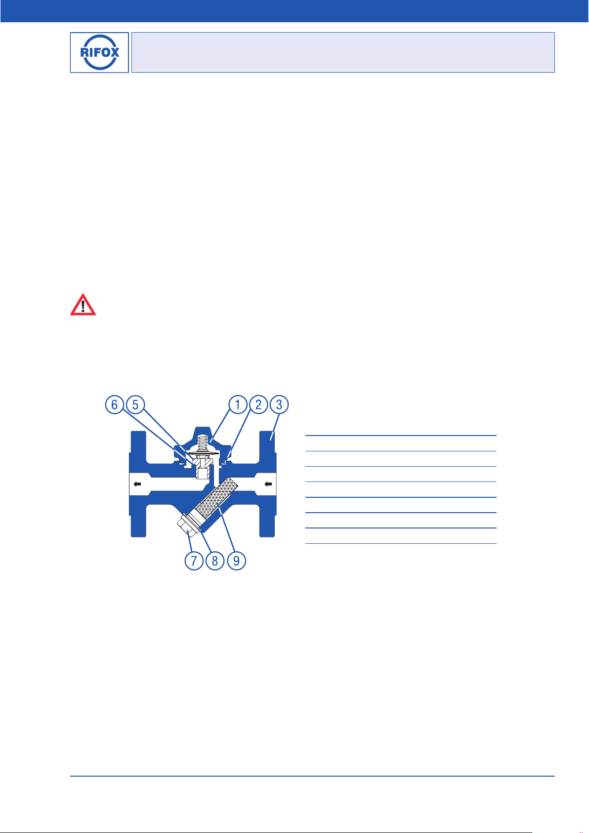
6.4 Spare parts
Only genuine spare parts can be used.
Picture 4: Model 10210
7 Conformity assessment
The pressure equipment described is a pressure-keeping component in accordance with the Pressure Equipment Directive
2014/68/EU.
DN15, DN20, DN25: according to Art. 4, Subs. 3, no CE-Mark.
DN40, DN50: Conformity verified through the identifying mark: CE 0525.
A detailed declaration of conformity assessment according to PED is available as separate document. Please request if
necessary, if not attached.
1 Upper housing: P250GH
2 Gasket: Novaphite
3 Flange part: P250GH
4 Housing screws: A4-70, DIN 933 / ISO 4017 (not visible)
5 Valve unit: 1.4104, 2.4610 & 1.4310
6 Gasket: Soft Iron
7 Plug: G ½“ (BSP) - 5.8
8 Gasket: Soft Iron
9 Strainer: 1.4301
Bertha-von-Suttner-Str. 9 D-28207 Bremen
Fax: +49 (0) 421 499 75 - 40
www.rifoxglobal.com
Page 3 of 3
sales@rifoxglobal.com
01/2017 -Di. Subject to modifications
 Loading...