


Version 1.8
MV Series
USER’S GUIDE
RIFATRON


1
FCC Compliance Statement
Model Name: MV Series (MV-1648, MV-1624, MV-824, MV-424).
This device complies with Part 15 of the FCC Rules. Operation is Subject to the following
two conductions: (1) this device may not cause harmful interference, and (2) this device
must accept any interference received, including interference that may cause undesired
operations.
WARNING
- Unauthorized reproduction of all or part of this manual is strictly prohibited.
- The figures in this manual are for illustration purposes only (may differ from the actual
product).
- The specifications and design of the product are subject to change without prior notice
for purposes of quality improvement.
CAUTIONS
To get the best use out of the product, be sure to read the cautions before using the
product. For safety, please take note of the following:
z Instructions before using the product
1. To prevent electric shock when installing, moving, or opening the DVR
and peripheral devices, connect and disconnect the cables as instructed.
All cables must be connected to grounded power outlets.
2. If the product is installed near a power outlet, make sure it can be
unplugged easily.
3. Do not use the DVR in water or in wet places.
4. Keep the vinyl packing materials used for the DVR or other peripheral
devices out of reach of children (may cause suffocation).
z Installation Environment of the DVR
1. Maintain the following conditions: operating temperature of 0˚C ~ 30˚C;
operating humidity of 10% ~ 80%
2. Install the DVR in a safe place that is free from external vibration.
3. Install the DVR in a well-ventilated place.
4. To protect the hard disk from data loss and breakdown, install the DVR
away from magnetic materials.
5. When using a rack other than the standard one, use a separate table with
sufficient spacing, i.e., 60cm from the floor, 50cm from the ceiling, and
20cm from the side and back walls and other objects.

2
z Safety Notes on the DVR
1. When installing additional boards and HDD, separate the power cable and
turn OFF power supplied to the DVR completely.
2. Keep the product away from heat-generating devices such as heaters.
3. Do not use a damaged power cord.
4. To prevent problems due to magnetic interference and electric surge, use
only grounded cables and power outlets.
5. If the power cord is connected, do not touch the power unit (if the power
cord is connected, electric current is still flowing internally even after the
switch is turned OFF).
6. Do not place a heavy object on top of the product.
7. Do not drop a conductive object in the ventilation holes.
8. Allot sufficient space for system cabling.
9. Use only the parts indicated in the manual. Do not disassemble, repair, or
modify the product without permission.
10. Incorrect system setup may cause malfunction.
11. Shut down the system normally as instructed in the manual
z Safety Notes on the Lithium Battery
1. Replace lithium batteries as instructed to avoid danger.
2. Dispose of used lithium batteries properly.
※ Warnings and Cautions are indicated as follows:
Possible injury or product damage
Risk of minor injury or product damage

3
STANDALONE
C/O/N/T/E/N/T/S
MV-1648 Series
FCC Compliance Statement ....................................................................... 1
WARNING ................................................................................................ 1
CAUTIONS ............................................................................................... 1
C/O/N/T/E/N/T/S ........................................................................................ 3
Chapter 1. Introduction ........................................................................... 7
1-1 About the Product .................................................................................................. 7
1-2 Major Features ....................................................................................................... 7
1-3 Components ........................................................................................................... 9
Chapter 2. Installation and Connection ............................................... 10
2-1 Name and Features of Each Part ......................................................................... 10
2-1-1 Front Part ................................................................................ 10
2-1-2 Back Part ................................................................................ 12
2-2 Installation and Connection .................................................................................. 14
2-2-1 Basic Connection ..................................................................... 14
2-2-2 Connection of Other Devices ..................................................... 15
Chapter 3. Operation and Setup Tools ................................................ 17
3-1 Remote Controller ................................................................................................ 17
3-2 Mouse .................................................................................................................. 20
Chapter 4. System Operation ............................................................... 21
4-1 Starting and Exiting the System ........................................................................... 21
4-1-1 Starting the System ................................................................... 21
4-1-2 Exiting the System .................................................................... 21
4-2 Monitoring ............................................................................................................ 21
4-2-1 Screen Division and Automatic Screen Conversion ....................... 21
4-2-2 Menus in Monitoring Mode ......................................................... 22
4-2-3 Moving the recording status window ........................................... 23
4-3 System Login ....................................................................................................... 23
4-3-1 User Account ........................................................................... 23
4-3-2 Login ...................................................................................... 24
4-3-3 Logout .................................................................................... 24
4-4 Audio Recording and Playback ............................................................................ 25
4-4-1 Setting up the Audio Recording .................................................. 25
4-4-2 Audio Live ............................................................................... 25
4-5 Viewing System Information and Changing the Display Setup.................................... 25
4-5-1 System Information ................................................................... 26
4-5-2 Channel Grouping ..................................................................... 26
4-5-3 Controlling the Screen Brightness ............................................... 27
4-5-4 Adjusting the Screen Contrast .................................................... 27
4-5-5 Adjusting the Hue ..................................................................... 27
4-5-6 Adjusting Saturation .................................................................. 27
4-5-7 Adjusting Sharpness ................................................................. 27
4-5-8 Camera Control ........................................................................ 27

4
4-5-9 TV Control ............................................................................... 28
4-5-10 Display/Hide Camera Name...................................................... 28
4-5-11 Adjusting the Screen Border ..................................................... 28
4-6 Spot Control ......................................................................................................... 29
4-7 Relay Out ............................................................................................................. 29
4-8 Playback ............................................................................................................... 29
4-8-1 Shifting to Playback Mode ......................................................... 29
4-8-2 Playback Menu ......................................................................... 29
4-8-3 Smart search ........................................................................... 29
4-8-4 Multi-Time ............................................................................... 30
4-8-5 Multi-Day ................................................................................ 32
4-8-6 Multi-Channel .......................................................................... 32
4-8-7 Playback and Control of Playback Speed ..................................... 33
4-8-8 Playback on a divided screen ..................................................... 34
4-8-9 Audio Playback ........................................................................ 34
4-8-10 Event Playback ....................................................................... 34
4-8-11 Go To The Date & Time ........................................................... 34
4-8-12 Go To The First ...................................................................... 35
4-8-13 Go To The Last ....................................................................... 35
4-9 Log List ................................................................................................................. 36
4-9-1 Log Types ............................................................................... 36
4-9-2 Viewing the System Log ............................................................ 37
4-10 Recording ........................................................................................................... 38
4-10-1 Recording Types ..................................................................... 38
4-10-2 Recording Setup ..................................................................... 38
4-10-3 Viewing the Recording Status ................................................... 38
4-10-4 Starting and Stopping Record All .............................................. 39
4-11 Search ................................................................................................................ 40
4-11-1 Selecting the Search Mode ...................................................... 40
4-11-2 Selecting the Search Method .................................................... 40
4-11-3 Search using the file list........................................................... 40
4-11-4 Multi-Channel Search .............................................................. 41
4-11-5 Multi-Time Search .................................................................. 41
4-11-6 Multi-Day Search .................................................................... 42
4-12 Backup ............................................................................................................... 43
4-12-1 Backup in Real-time Monitoring Mode ....................................... 43
4-12-2 Backup in Search Mode ........................................................... 43
4-12-3 Backup in Log Mode ............................................................... 43
4-12-4 Backup in Playback Mode ........................................................ 44
4-12-5 Common Backup Process ........................................................ 44
4-13 Snapshot ............................................................................................................ 46
4-14 Print .................................................................................................................... 46
4-15 PTZ Camera Control .......................................................................................... 46
4-15-1 Conditions for Using the PTZ Features ...................................... 46
4-15-2 Shifting to PTZ Mode ............................................................... 47
4-15-3 PTZ Control ............................................................................ 47
Chapter 5. System Setup ...................................................................... 49
5-1 Main Setup ........................................................................................................... 49
5-1-1 Starting the Main Setup ............................................................. 49

5
5-1-2 Data Selection (Data 1 ~ Data 4)................................................ 49
5-1-3 Shifting to Recording Setup Mode .............................................. 50
5-1-4 Saving the Recording Setting ..................................................... 51
5-1-5 Recording Setup ....................................................................... 51
5-1-6 Recording Schedule .................................................................. 60
5-1-7 System .................................................................................... 63
5-1-8 Storage ................................................................................... 70
5-1-9 NTP ........................................................................................ 76
5-1-10 Advanced .............................................................................. 82
5-2 Additional Setup ................................................................................................... 84
5-2-1 Selecting the Additional Setup Menu ........................................... 84
5-2-2 PTZ setup ................................................................................ 84
5-2-3 Network setup .......................................................................... 86
A/P/P/E/N/D/I/X ....................................................................................... 90
1. PTZ Camera Protocol ................................................................ 90
2. Recommended HDD .................................................................. 90
3. Recommended USB2.0 Device ................................................. 90
4. Memory Stick ............................................................................. 91
5. 2.5’’ Potable USB HDD .............................................................. 91
6. CD-RW, DVD-RW ....................................................................... 91
7. IEEE1394 Exterial Storage ........................................................ 91
8. DAT(Interior/Exterior) ................................................................ 91

6

7
Chapter 1. Introduction
1-1 About the Product
The MV series is a digital video monitoring equipment that can monitor, record, play, and
transmit video contents using 16, 8, or 4 cameras. Using the front buttons, remote
controller, and mouse, the user can control the equipment. The MV series boasts of
strong networking capabilities such as remote monitoring and remote configuration. Up
to 480 or 240 fps can be recorded; the following functions are also supported:
As a digital image monitoring equipment that can display images inputted from up to 16
cameras, iMDVRS-1648(S)/1624(S) digitally records high-quality images using various
video recording modes and displays them as clean quality images.
For users’ convenience, front touch pad, remote controller, and mouse are provided.
Powerful network functions including remote monitoring and remote system setup
modification are also supported.
The maximum recording frame rate for MV Series is 480fps/240fps.
1-2 Major Features
z Stable Standalone DVR (Embedded Linux)
z Video output
- Monitor Output : 1 BNC, 1 VGA
- Loop Output : 16 BNC
- Spot Output : 1 BNC
z 480/240fps display/simultaneous operation of video recording/playback
- 480fps : MV-1648
- 240fps : MV-824/424
Resolution
- NTSC : 352×240, 704×240, 704×480
- PAL : 352×288, 704×288, 704×576
z Compression type : MPEG4 (video) / G.726 (audio)
z Backup/Copy – Ethernet, IEEE1394, USB2.0
z System operation – Front Button / Remote controller / Network / USB2.0
mouse / Key controller
z Audio Input
- 16 channel : MV-1648
- 8 channel : MV-824
- 4 channel : MV-424

8
z Various network interfaces
- Cable modem, Ethernet , ADSL/DHCP client
z System automation (all features are remote-controllable)
z NTP support
z Various recording modes
- Auto, Continuous, Event (sensor, motion, sound) recording
z Scheduled recording feature
z Multi-language support, Automatic emailing
z PTZ control through RS485 communication
z Remote monitoring software/Remote monitoring through the web
browser/PDA
z Storage device
- Internal storage device : Max. of 2HDD, Max. of 1TB
- External storage device : IEEE1394 RAID external storage device

9
1-3 Components
After unpacking the product, check whether the following accessories are included:
- Remote Controller
- CMS CD (Remote Monitoring Software)
- Two AAA 1.5V batteries
- Power Cord
- User Manual
- Rack Mounting Handle
10
Chapter 2. Installation and Connection
2-1 Name and Features of Each Part
The front part of MV Series features an easy-to-use button; various interfaces are located
on the rear part. They can easily be mounted on a standard rack using the mounting
handles (Left/Right).
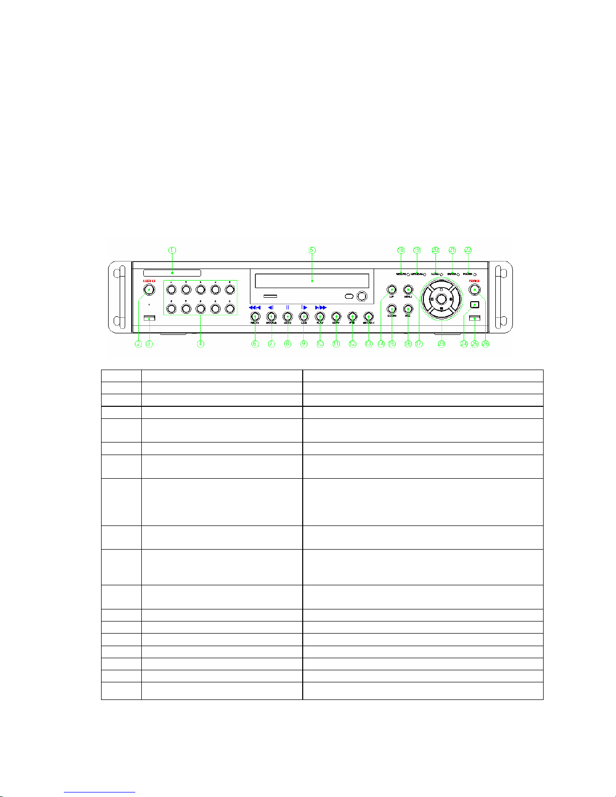
2-1-1 Front Part
No. Name Features
1 LABEL
Brand Name and Model Name
2 RECORD
All channel Record/Stop
3 USB
Connection ports to USB mouse and memory stick
4 Number
System login and turn ON in other number input
mode
5 ODD
CD-RW and DVD-RW
6
Reverse Play / Fast Reverse
RELAY
Backward Playback/Rewind (in Playback mode)
Relay Control (in Monitoring mode)
7
Reverse Frame by Frame or
TAB
STATUS
Backward Playback Frame by Frame (in Playback
mode)
View System Configuration/Change Display
Configuration (in Monitoring mode)
8
PAUSE
LOCK
Pause (in Playback mode)
Lock (in Monitoring mode)
9
Forward Frame by Frame or
TAB
LOG
Playback Frame by Frame (in Playback mode)
View System Log (in Monitoring mode)
10
Forward Play / Fast Forward
PLAY
Playback/Fast Forward (in Playback mode)
Play back (in Monitoring mode)
11 COPY
Play back Recorded Video
12 PTZ
Change Pan Tilt Zoom Mode
13 SEARCH
Search Recorded Images
14/15 UP/DOWN
Speed and Volume Up/Down
16 ESC Button
Exits the current menu or selects the upper menu
17 MENU
Various Modes
18 RECORD LED
Green LED turned on upon HDD operation

11
19 NETWORK LED
Green LED turned ON during remote access
20 ALARM LED
Red LED turned on upon the occurrence of event
or motion
21 ERROR LED
Red LED turned on upon fan defect or recording
interruption
22 POWER LED
Power On/Off
23 SELECT
Selects the category or executes automatic screen
conversion
23 MOVE & DISPLAY
Moves from one category to another or changes
the display mode
24 IR Senso
r
Remote controller input part
25 USB Port
Connection port to the USB mouse and USB
memory stick
26 POWER Button
Turn the system power ON or OFF

12
2-1-2 Back Part
z 16ch Back Part (MV-1648/1624)
No. Name Features Type
1 AC IN
Power cable connection to the body
2 AC Selector
110V, 220V voltage selection (※ not available for
the Free Voltage case)
3
RS485
DIO
Connection for the PTZ camera control cable
Sensor/Relay extension board connect ion
Terminal
Block
4
CAMERAIN
LOOP OUT
Connection for the video camera
Connection for the video signal loop-back output
BNC
BNC
5 AUDIO IN
Audio input connection RCA
6
NTSC/PAL
VGA/TV
Used to select the video input format
Used to select the video output format
DA-2
7 iEEE1394
External backup device connection 1394 Port
8 Ethernet
ADSL, cable modem, and Ethernet 10/100 Base-T
connection
RJ-45
9 RS-232C
Serial cable connection for system upgrades
& checking
D-SUB 9P
10
V
GA
Connection for the VGA monitor D-SUB 15P
11 TV
Connection for the CCTV monitor(divided screen) BNC
12 SPOT
CCTV monitor connection to output image from the
channel generating an event signal (full screen)
BNC
13 AUDIO OUT
Audio output connection (Line Only output) RCA

13
z 8ch Back Part (MV-824)
z 4ch Back Part (MV-424)
14
2-2 Installation and Connection
2-2-1 Basic Connection
Connect the CCTV camera, CCTV monitor (or PC monitor), and USB mouse to the DVR
as shown below.
Connected Device DVR Terminal
1
CCTV camera
Video input
2
CCTV monitor (or PC monitor) TV (or VGA)
3
Mouse
USB
1. The input video type must be either NTSC or PAL; these two types must not
be used together.
2. Select the input video format (NTSC/PAL) using the Config switch on the rear
side of the product.
3. Select the output monitor type (VGA/TV) using the Config switch on the rear
side of the product.

15
2-2-2 Connection of Other Devices
Connect the PTZ controller cable, audio input/output, network, and sensors as shown
below.
.
Connected Device DVR Terminal
1
PTZ Camera RS485
2
SPOT Monitor(CCTV Monitor) SPOT
3
Mike / Speaker Audio Input / Audio Output
4
LAN Cable Ethernet
5
Sensor / Relay DIO (Digital Input/Output)
1) PTZ Camera
① For the PTZ camera, connect the control cable of the PTZ camera to the terminal block
on the rear side of the DVR.
② Connect the RS485 wire to the terminal block on the rear side of the DVR. Connect
TRX+ and TRX-.
2) SPOT Monitor
The Spot monitor is a CCTV monitor that displays events.
SPOT※ : The Spot monitoring function displays video from the channel detecting an
event (motion, sensor, or sound) in full screen. Events are checked every second. If
events are detected from multiple channels, the video from the channel with the latest
event is displayed.
3) Audio Input/output
Audio ports are basically provided; 16 input lines and 1 output line are supported.
4) Sensor/Relay
Connect to the rear side of the product using the cable.
Sensor Input Relay Output
16ch DVR 16 4
8ch DVR 8 2
4ch DVR 4 1

16
(1) Sensor Connection
① Connect to the input port of the terminal block.
② Each input terminal may be connected regardless of the channel number.
Sensor types include Normal Close (NC) and Normal Open (NO). For more
information on setup by sensor type, refer to {Data Setup} Æ {Event Setup} Æ
{Sensor}.
Normal Close (NC): Normally closed; opens when a signal is received
Normal Open (NO): Normally open; closes when a signal is received
(2) Relay Connection
③ Outputs alarm signals to external devices such as LED and siren by relaying them to
these external devices
④ Connect the external alarm device to the COM or Out port of the sensor/relay terminal
block.
Relay types include Normal Close (NC) and Normal Open (NO). For more
information on setup by sensor type, refer to {Data Setup} Æ {Event Setup} Æ
{Sensor}.
Normal Close (NC): Normally closed; opens when a signal is received
Normal Open (NO): Normally open; closes when a signal is received

17
Chapter 3. Operation and Setup Tools
The user can easily operate the MV series using the front buttons, remote controller, and
mouse.
3-1 Remote Controller
A
, Basic control buttons
POWER
Turns the system power
ON or OFF
RECORD
Records all channels or
stops recording all
channels
1
~
0
NUMBER
Enables input of numeric
data
ID
Sets up the remote
controller ID
B. System operation and setup buttons
MENU
Data, Schedule, System
Set up
ESC
Exits the current menu
or selects the upper
menu
SEARC
H
Searches recorded
images
SELECT
Selects the category or
executes automatic
screen conversion
COPY
Copy Recorded Video
PTZ
Shifts to PTZ camera
control mode
MOVE
Moves from one category
to another or changes the
display mode
UP/
DOWN
Speed and Volume
Control
18
C. Search Button (Play mode)
Play /
Fast Forward
Play/Fast-forward
Frame by Frame
Play frame by frame
Pause
Pause
Reverse Frame by Frame
Reverse play frame by frame
Reverse Play /
Fast Reverse
Reverse play/ Rewind
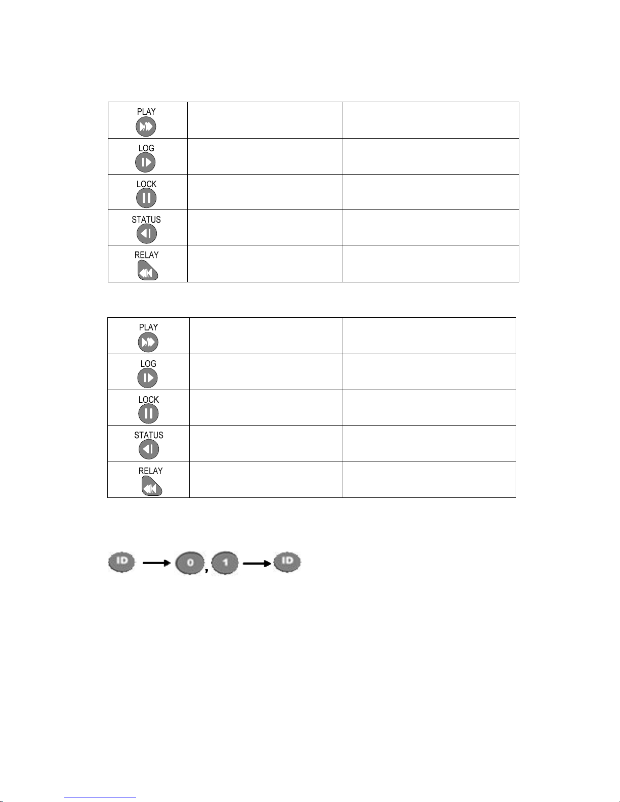
D. Buttons for other features (Monitoring mode)
PLAY
Plays the recorded images
LOG
Enables viewing the system
log list
LOCK
Locking the system
STATUS
Views system information and
changes the display setup
RELAY
View Relay Status and Manual
Operation
※ Setting up the remote controller ID
Example) When the remote controller ID is set to 1

19
Press the [ID] button, enter a two-digit remote controller ID, and press the [ID] button
again.
To control all DVRs with different IDs, set the remote controller ID to 999.
,
,

20
3-2 Mouse
The USB mouse can be used to operate the system.

21
Chapter 4. System Operation
4-1 Starting and Exiting the System
4-1-1 Starting the System
① With the power connected to the player, press the Power button on the remote controller.
② After the system is booted, images of all connected channels will be displayed.
4-1-2 Exiting the System
The default password for the local administrator is “00000.”
※ To change the password, select {Main Setup} Æ {System} Æ {Local
Administrator’s Password}.
① Press the Power button on the remote controller.
② On the password input screen, enter a new password using the numeric buttons and the
arrow keys.
③ After authentication is completed, the alarm will sound for 20 seconds, and the system
will be terminated.
4-2 Monitoring
After the system is booted, images will be displayed on a screen divided into 16 sub-screens
(in the case of 16-channel DVR). The screen can be divided into 1, 4, 9, and 16 sub-screens.
Auto-sequencing is possible in each mode.
4-2-1 Screen Division and Automatic Screen Conversion
Full Screen (16 groups)
Use the Full Screen mode.
To view a certain channel, select the desired channel using the numeric buttons.
4 Sub-Screens
(4 groups)
Use the 4 Sub-Screen button.

22
9 Sub-Screens (2 groups)
Use the 9 Sub-Screen button.
16 Sub-Screens (1 group)
Use the 16 Sub-Screen button.
The user can view an image on full screen by double※ -clicking the 4/9/16 Sub-Screen
mode. Double-click any part of the screen to return to the previous mode.
The user can select the automatic change mode by selecting the Select (Automatic ※
Change) button in 1/4/9 Sub-Screen mode. Click the Select button again to return to the
previous mode.
Using the Up/Down button, the user can select the change interval from 1 second to 5 ※
seconds (to set the change interval, however, multiple cameras should be connected).
The user can also set the change interval by right※ -clicking any part of the screen.
4-2-2 Menus in Monitoring Mode
In real-time monitoring mode, the user can control all functions using {Live menu}.

23
[Figure 4-1. Live Menu]
① Press or right-click the Menu button. The Live menu will then appear as shown in Figure
4-1.
② Select the desired item using the arrow keys.
③ Press the ESC button or right-click the Menu button to hide the menu.
4-2-3 Moving the recording status window
In real-time monitoring or playback mode, use the mouse to change the position of the
recording status window.
① Drag the cursor to the date/time. The recording status window will then be bordered.
② At this time, drag the recording status window.
The user can move the recording status window using only the mouse.※
4-3 System Login
4-3-1 User Account
System users are divided into local administrators and general users.
The local system administrator can use all functions.
Local
admin
The local administrator can use all functions: System Power On/Off,
Setup, Monitoring, and Playback (remote access is not possible,
however).
User
Up to four users are allowed. Each user can access the functions
depending on the given authorities.
The administrator can set the authorities by selecting {Main Setup} Æ
{System} Æ {Add User}.

24
Functions※
Network Live
Enables viewing real-time images upon network access
Playback
Enables viewing the Recorded Screen
Copy (Download)
Enables copying and downloading files from the
network
PTZ Control
PTZ camera control
Main/Additional Setup
Data Setup, Recording Schedule, System, Storage,
NTP, Advanced Setup, PTZ Camera, Network,
Camera/TV Setup
Network Upgrade
Remote network upgrade
V
iew Hidden Channels on
Network
Enables viewing hidden channels on the network
4-3-2 Login
To use the App. Setup, Search, Playback, Copy, and Camera/TV Setup functions, the user
should log in first for security purposes.
[Figure 4-2. Login Window]
① On the real-time monitoring window, select {Live Menu} Æ {Login}. The login window
will then appear as shown in Figure 4-2.
② Enter the password.
4-3-3 Logout
After logging out, the user cannot use functions such as Main Setup, App. Setup, Search,
Playback, Copy, and Camera/TV Setup functions.
① On the real-time monitoring screen, select {Live Menu} {Logout}.
When you set {Main Menu} Æ {System} Æ {Menu Time Out},
there will be Auto Logout if there is not any operation during the limited time.
To use the Lock, Recording, and System Shutdown functions, all users including logged※ -in
users should be authenticated first.

25
4-4 Audio Recording and Playback
4-4-1 Setting up the Audio Recording
① On the real-time monitoring screen, select {Live Menu} Æ {Main Setup}.
② The main setup window will then appear as shown in Figure 5-1.
③ Select {Recording Setup} Æ {Recording} Æ {Audio} using the arrow keys and the
Select button.
④ Set up the audio.
4-4-2 Audio Live
① On the real-time monitoring screen, select {Live Menu} Æ {Control} Æ {Audio}.
② Select the audio channel.
4-5 Viewing System Information and Changing the Display Setup
Basic system information is displayed as shown in Figure 4-3.
[Figure 4-3. Recording Status Window]
26
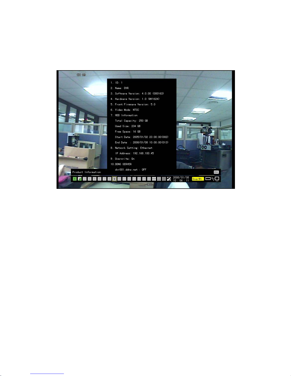
4-5-1 System Information
① On the real-time monitoring screen, select {Live Menu} Æ {Status}.
② Product mode information will then be displayed as shown in Figure 4-4.
[Figure 4-4. Product Information Window]
※ The product ID shall be unique (1~99, 255). Only when the product ID and the remote
controller ID match can the DVR system be remotely controlled.
4-5-2 Channel Grouping
① On the real-time monitoring screen, select {Live Menu} Æ {Channel Grouping}.
② The user can select the screen split mode by selecting {Menu} Æ {Display Setting}.
③ On the monitoring screen, go to the channel selection window and select the channel to
be changed by group.
④ On the selection window, select a channel using the arrow keys and the Select button.
Group Setup is not supported for the 1※ -split mode.
The user can change the channel location in the group using the mouse.※
Changing the screen split mode causes other split modes to be changed as well.※

27
4-5-3 Controlling the Screen Brightness
① On the real-time monitoring screen, select {Live Menu} {Camera/TV Setting}
{Brightness}.
② To adjust the brightness, select a channel on the screen.
③ Control the brightness of the selected channel using the arrow keys.
④ Activate the channel selection window using the [ESC] button and adjust the brightness
of the other channels by repeating steps 3 and 4.
4-5-4 Adjusting the Screen Contrast
① On the real-time monitoring screen, select {Live Menu} {Camera/TV Setting}
{Brightness}.
② To adjust the brightness, select a channel on the screen.
③ Control the brightness of the selected channel using the arrow keys.
④ Activate the channel selection window using the [ESC] button and adjust the brightness
of the other channels by repeating steps 3 and 4.
4-5-5 Adjusting the Hue
① On the real-time monitoring screen, select {Live Menu} {Camera/TV Setting} {Hue}
② To adjust the Hue, select a channel on the screen.
③ Control the hue of the selected channel using the arrow keys.
④ Activate the channel selection window using the [ESC] button and adjust the hue of the
other channels by repeating steps 3 and 4.
4-5-6 Adjusting Saturation
① On the real-time monitoring screen, select {Live Menu} {Camera/TV Setting}
{Saturation}
② To adjust the saturation, select a channel on the screen.
③ Control the saturation of the selected channel using the arrow keys.
④ Activate the channel selection window using the [ESC] button and adjust the saturation
of the other channels by repeating steps 3 and 4.
4-5-7 Adjusting Sharpness
① On the real-time monitoring screen, select {Live Menu} {Camera/TV Setting}
{Sharpness}.To adjust the sharpness, select a channel on the screen.
② Control the sharpness of the selected channel using the arrow keys.
③ Activate the channel selection window using the [ESC] button and adjust the sharpness
of the other channels by repeating steps 3 and 4.
4-5-8 Camera Control
① On the real-time monitoring screen, select {Live Menu} {Camera/TV Setting}

28
{Camera}.
② To control the camera, select a channel on the monitoring screen.
③ Use the arrow buttons to adjust the camera for the selected channel.
④ Use the [ESC] button to activate the channel selection window and adjust the camera
for the other channels by repeating steps and .②③
※ Moving the monitor up, down, right, or left excessively may cause black or gray areas
to appear on the screen. The level at which such condition does not occur is the proper
control range for the monitor.
4-5-9 TV Control
① On the real-time monitoring screen, select {Live Menu} {Camera/TV Setting} {TV
Out}.
② Adjust the CCTV monitor up/down or right/left using the arrow keys.
Moving the monitor up, down, right, or left excessively may cause black or gray areas ※
to appear on the screen. The level at which such condition does not occur is the proper
control range for the monitor.
4-5-10 Display/Hide Camera Name
① On the real-time monitoring screen, select {Live Menu} Æ {Display Setting} Æ
{Name}(Camera Name).
② Select the On/Off status using the arrow keys and the Select button.
4-5-11 Adjusting the Screen Border
① On the real-time monitoring screen, select {Live Menu} {Display Setting}
{Border}.
② Select the desired item using the arrow keys and the Select button.
③ After assigning the setup value per field, press the [ESC] button to exit the Border Line
setup mode.
Border setting fields※
Field Setup Value Description
Mode
setup
On
Display the border for each channel screen in
varying modes.
Off
Hide the border for each channel screen in
varying modes.
Type
Internal Hide the external border line.
All Display all border lines.
Width
2, 4 Set the width of the border.
Color
Black, White, Red, Green,
Blue
Set the color of the border.

29
4-6 Spot Control
① On the real-time monitoring screen, select {Live Menu} Æ {Control} Æ {Spot} or press
“0” on the remote controller
② Select a channel. The spot monitoring setting window will then close, and the selected
channel screen will be displayed.
4-7 Relay Out
① On the real-time monitoring screen, select {Live Menu} Æ {Control} Æ {Relay Output}
or press “0” on the remote controller.
② Selecting a relay channel enables outputting/canceling the relay.
4-8 Playback
4-8-1 Shifting to Playback Mode
On the real-time monitoring screen, select {Live Menu} Æ {Playback} to shift to Playback
mode. The contents will then be played back from the point when playback was last stopped.
4-8-2 Playback Menu
In Playback mode, the user can control all functions using {Playback Menu}.
[Figure 4-5. Playback Menu]
① Select or right-click the Menu button. The Playback menu will then appear as shown in
Figure 4-5.
② Select the desired item using the arrow keys.
③ Press the ESC button or right-click the Menu button to hide the menu.
4-8-3 Smart search
This function is used to search an image for the object movement at a specific zone fast
30
① In Playback mode, select {Playback Menu} {Smart Search}.
② The user can execute smart search by selecting a channel using the arrow keys and the
Select button.
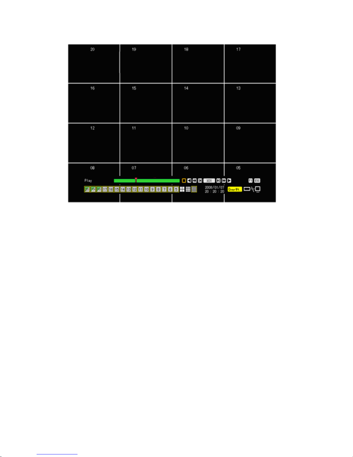
4-8-4 Multi-Time
The user can play back the video contents of a certain channel recorded at different times. The
video contents can be sorted by time in ascending or descending order.

31
Time
[Figure 4-6. Multi-Time Playback]
32
① In Playback mode, select {Playback Menu} {Multi-Time}.
② The user can execute multi-time playback by selecting a channel using the arrow keys
and the Select button.
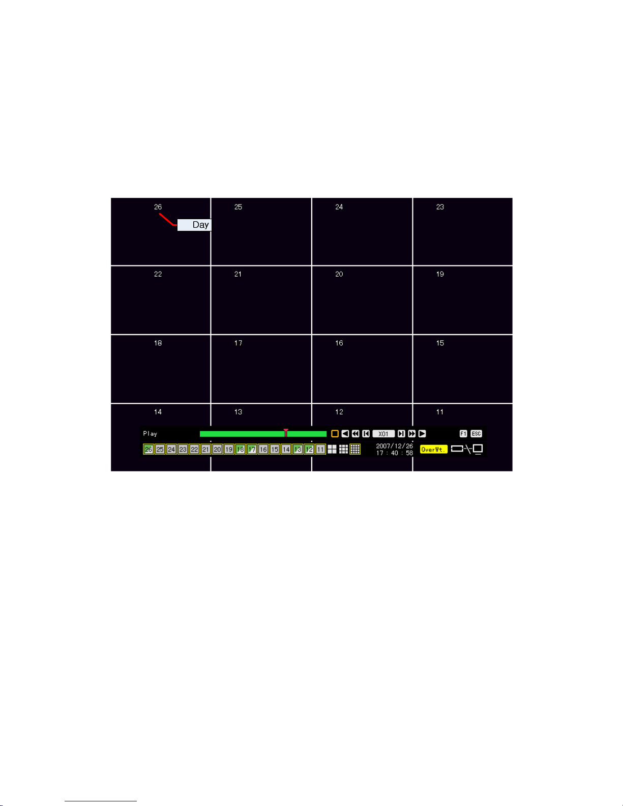
4-8-5 Multi-Day
The user can play back the video contents of a certain date recorded on different dates.
The video contents can be sorted by date in ascending or descending order.
[Figure 4-7. Multi-Day Playback Screen]
① In Playback mode, select {Playback Menu} Æ {Multi-Day}.
② The user can execute multi-day playback by selecting a certain channel using the arrow
keys and the Select button.
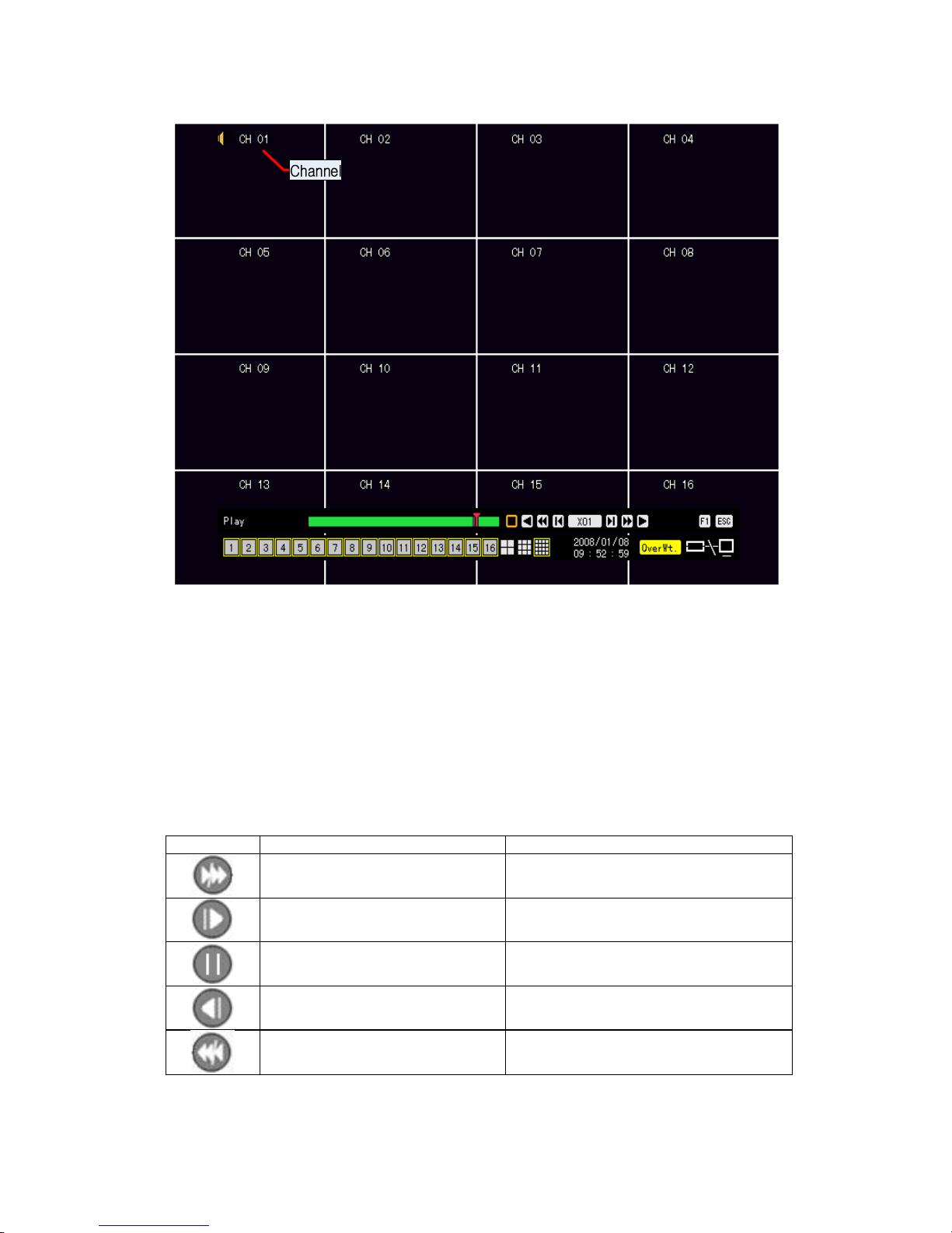
4-8-6 Multi-Channel
The user can play back the video contents at multiple times as recorded in a certain time zone.
In Playback mode, multi-channel playback can be executed by selecting {Playback Menu} Æ
{Multi-Channel}.
33
[Figure 4-8. Multi-Channel Playback Screen]
4-8-7 Playback and Control of Playback Speed
① In Playback mode, the user can play back video contents using the functions below.
② After the data is played to the end, the data of the next time zone will be automatically
searched and played (this function is possible only in Multi-channel Playback mode;
both backward playback and forward playback are possible).
③ Using the Up/Down button, the user can adjust the playback speed between (ⅹ1/29)
and (ⅹ29) and fast forward or rewind at a speed between (x30) and (x300).
※ Description of the Search Buttons
Button Name Features
Forward playback/Fast
forward
Playback forward (ⅹ1)/
Fast forward (ⅹ30)
Forward Frame by Frame
Frame-by-frame playback
Pause
Pause
Reverse frame by frame
Reverse playback frame by frame
Reverse playback/Fast
reverse
Playback in reverse (ⅹ1)/
Rewind (ⅹ30)

34
Speed Down
Decreases the playback speed
Speed Up
Increases the playback speed
[Figure 4-9. Playback Status and Control Window]
4-8-8 Playback on a divided screen
① In Playback mode, the user can split the screen as in the monitoring mode.
4-8-9 Audio Playback
① In Playback mode, select {Playback Menu} Æ {Audio}.
② Select an audio channel for playback using the arrow keys and the Select button.
4-8-10 Event Playback
This feature finds and plays specific events only in the recorded data.
① In Playback mode, select {Playback Menu} Æ {Event}.
② Select an event using the arrow keys and the Select button.
4-8-11 Go To The Date & Time
The user can play back the data recorded at a specified time on a specified date.
① In Playback mode, select {Playback Menu} Æ {Go To The Date & Time}.
② On the time setting window, set the folder count, time, and channel using the arrow keys
and the Select button.
③ After confirming all settings, select the OK button. Data will then be played starting from
the specified time point.
※ The folder (directory) count is used to select a folder of a different time.
※ The user can set the channel in Multi-day Playback or Multi-time Playback mode only.

35
4-8-12 Go To The First
The user can search and play back the first recorded data.
① The oldest data can be played back by selecting {Playback Menu} ( {Go To The First}
in Playback mode.
4-8-13 Go To The Last
The user can search and play back the last recorded data.
① The latest data can be played back by selecting {Playback Menu} ( {Go To The Last}
in Playback mode.
The user can use the Go※ -To-The-First and the Go-To-The-Last functions only in {Multi-
Channel} mode.

36
4-9 Log List
The user can record the logs of all system operations such as system power on/off, system
setup, network connection/disconnection, etc.
4-9-1 Log Types
Log Types
General
Logs related to power ON/OFF, file copy/backup failure, setup
start/end, playback, and other basic system operations
Recording Event
Logs related to recording, e.g., motion detection, sensor
detection, and sound detection
Network
Logs related to network operations e.g., network login,
network logout, and network live
Fail
Logs related to system operation failures, e.g., signal loss and
network connection failure
All
Logs related to all system operations

37
4-9-2 Viewing the System Log
[Figure 4-10. Log List Window]
① Select {Live Menu} Æ {Log} in real-time monitoring mode or {Playback Menu} Æ {Log} in
Playback mode. The Log List window will then appear as shown in Figure 4-10.
② On the activated calendar window, Select the desired date (year/month/date) using the
arrow keys and the Select button.
③ The user can check the time and the log type using the arrow keys in the log list.
④ Use the Up/Down button to check the logs by time and type on each page.
⑤ The user can shift to Playback mode in a certain time zone for the log list by selecting
the Playback button (playback will start from the time point when logs are saved).
Viewing Time Change-related Log Data
The stored data folder is updated each time the user changes the time. A blue triangular
icon is displayed on the date each time a change is made in the date on the calendar
window. Otherwise, a red triangular icon is displayed on the unchanged date. To view
the log details, select the desired date with a red icon. Selecting a date with a blue icon
causes the changed date list to appear.

38
4-10 Recording
4-10-1 Recording Types
The MV series supports various recording types as shown below.
Recording
Type
Description
Automatic
Set the event recording frame and general recording frame separately.
Depending on the set value, select the recording type automatically
and proceed with the recording.
When motion, sensor, or sound is detected, the event recording frame
will be selected. Otherwise, the general recording frame will be
selected.
Continuous
Continuous recording will be done based on the general frame value.
Motion
When motion is detected, recording will be done based on the event
frame value.
Sensor
When input signal from an external sensor is generated, recording will
be done based on the event frame value.
Sound
When sound is detected, recording will be made based on the event
frame value.
4-10-2 Recording Setup
The user can set the recording type by selecting {Main Setup} Æ {Data Setup}. For more
information, see {Main Setup} Æ {Data Setup} Æ {Recording Setup}.
4-10-3 Viewing the Recording Status
The user can view the recording status, hard disk status, and network connection status of
each channel as shown in Figure 4-3.
▶ Recording Status by Shape
Triangle Only video is recorded.
Triangle Only audio is recorded.
Square Both audio and video are recorded.
▶ Recording Status by Color
Green Continuous recording is in progress.
Red Motion recording is in progress.
Blue Sensor recording is in progress.
Yellow Sound recording is in progress.
Transparent No recording is being done.

39
▶ Hard Disk Status
※ To turn on/off HDD Overwrite, select {Main Setup} -> {Storage Device}.
Overwrite on Hard Disk Do Not Overwrite on Hard Disk
▶ Network Access Status
Network Connected Network Disconnected
4-10-4 Starting and Stopping Record All
In real-time monitoring mode, the user can start or stop the recording of all channels by
selecting {Live Menu} Æ {Recording}.
1) Stopping Record All
① In real-time monitoring mode, select {Live Menu} Æ {Recording}.
② Enter the password of the local system administrator.
③ On the recording stop confirmation window, select the Yes button.
④ Any channel recording in progress will then stop, and the corresponding status will be
displayed on the recording status window.
2) Starting Record All
① In real-time monitoring mode, select {Live Menu} Æ {Recording}.
② On the login window, enter the password of the local system administrator.
③ The recording of all channels will then start based on the previous setting, and the
recording status will be displayed.
Overwrite
Overwrite
Overwrite
40
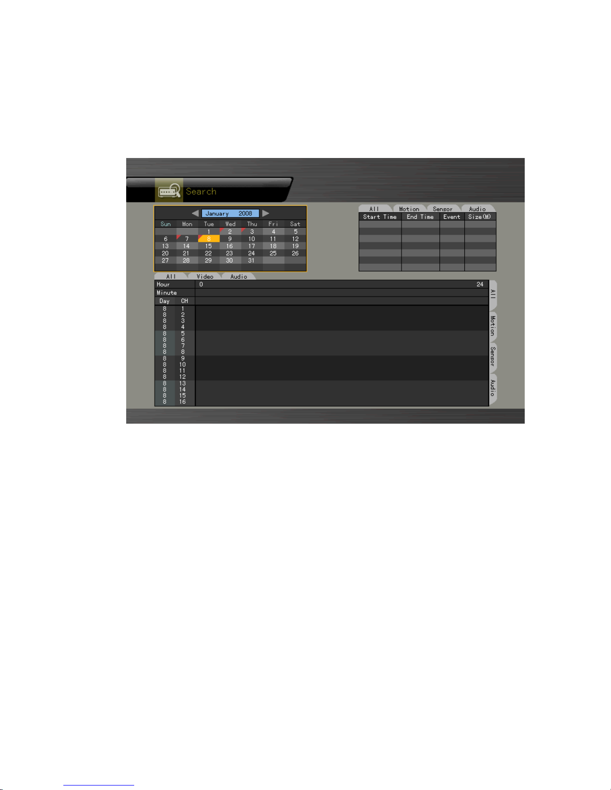
4-11 Search
4-11-1 Selecting the Search Mode
To shift to Search mode, select {Live Menu} Æ {Search} in real-time monitoring mode or
{Playback Menu} Æ {Search} in Playback mode as shown in Figure 4-11.
[Figure 4-11. Search Window]
4-11-2 Selecting the Search Method
The user can execute a search using bar graphs (Multi-Channel, Multi-Time, Multi-Day) or
file lists (Multi-Channel). One of these two methods can be used.
4-11-3 Search using the file list
① Select the desired search date. The one-hour file list for the recorded video will then be
displayed.
② Select the desired file using the arrow keys.
Viewing the List of Files with Changed Time
1) Whenever a user changes the time by selecting {Main Setup} Æ {NTP} Æ
{Date and Time}, a new folder (directory) is created, and the files recorded in
the previous channel are displayed in light blue.
2) Selecting a light blue-colored file causes a window where files of different
folders (before the time change) to appear.

41
※In Multi-Channel search mode, the user can execute a search using the file list only.
Current
Recorded video file based on the current system time
Old_Numbe
r
Recorded video file based on the previous system time
4-11-4 Multi-Channel Search
The user can play back the video contents of different channels recorded in a certain time
zone.
① On the calendar window, select the desired date (year/month/day) using the arrow keys
and the Select button.
② On the calendar window, select the desired search date. The recorded one-hour video
of each channel is then displayed in a bar graph.
Green
Indicates continuous recording
Red
Indicates motion recording
Blue
Indicates sensor recording
Yellow
Indicates voice recording
Light blue
Indicates that recording was done before the time was changed
③ Move the time line to a specific time point using the arrow keys or the numeric buttons
and press the Search button.
④ Selecting the time causes the recorded video for each channel to be displayed as a bar
graph in minute units.
⑤ Move the time line to a certain time point using the arrow keys and the numeric buttons
and press the Select button. Playback will then start from the specified time point.
Viewing the time change via the status bar
1) Files stored in the folder before the time change will be displayed in light blue
on the status bar.
2) By selecting a light blue-colored file, the user can view the list of files saved in
different folders (before the time change).
4-11-5 Multi-Time Search
The user can play back the video contents of a certain channel recorded in different time
zones.
Multi-time data can be searched in Multi-time Search mode.

42
① The user can search data by date as in the Multi-Channel Search mode.
② Time zones and channels may be viewed by selecting the desired date.
③ Select the start time and the channel using the arrow keys.
④ The hourly recorded video of the selected channel will then be displayed as a bar graph
in minute units.
⑤ Move the time line using the arrow keys and the numeric buttons and specify the time.
Afterward, press the Start button and play back the contents.
※ A time zone consists of 16 hours.
4-11-6 Multi-Day Search
The user can play back the video contents of a certain channel recorded on different dates.
Video contents of other dates can be searched in Multi-Day Search mode.
① The user can search video contents by date as in the Multi-Channel Search mode.
② Select the desired date. The date list, time, and channel will then be sorted in
descending order.
③ Select the desired time and channel using the arrow keys.
④ The recorded video of the selected channel will then be displayed as a bar graph in
minute units.
⑤ Move the time line using the arrow keys and the numeric buttons and specify the time.
Afterward, press the Select button and play back the contents.
※ A day unit consists of 16 consecutive hours a day.

43
4-12 Backup
To back up data, the PC shall be equipped with CD and DVD or connected with a storage
device such as HDD, CD, DVD, or DAT via the USB 2.0 port. For the supported portable
storages, see the Appendix. The user can back up data in real-time monitoring, search, log, or
playback mode.
The DAT device uses tar utility to bundle and back up files/directories.
4-12-1 Backup in Real-time Monitoring Mode
① In real-time monitoring mode, select {Live Menu} {Copy} {Backup}. The backup
menus will then appear as shown in Figure 4-12.
② The automatic backup time is set to 5 minutes before the Copy (Backup) button is
pressed, and the end time, to the time the Copy (Backup) button is pressed.
③ All channels containing data at the time of backup are backed up automatically.
Depending on the divided screen mode, however, only those channels that can be
viewed may be selected.
④ For the remaining backup procedures, see {Backup} ( {Common Backup Procedure}.
Data obtained before the time was changed cannot be backed up.
4-12-2 Backup in Search Mode
① Select {Search} ( {Multi-Channel} ( {Minute}.
② Select {Menu} ( {Copy} ( {Backup}.
③ The automatic backup start time is set to the year/month/date/hour/minute set in search
mode, and the end time, to the last minute/second of the data existing at the selected
time.
④ All channels with existing data at the time of backup are backed up automatically.
⑤ For the remaining backup procedures, see {Backup} ( {Common Backup Procedure}.
4-12-3 Backup in Log Mode
① Select a date in {LOG} followed by a log related to the data to be backed up.
② Select {Menu} ( {Copy} ( {Backup}.
③ The automatic backup time is set to 5 minutes before the selected log is generated, and
the end time, to the time the selected log is generated.
④ All channels with existing data at the time of backup are backed up automatically. If a
log has been generated for a specific channel, however, then only that channel is
selected.
⑤ For the remaining backup procedures, see {Backup} ( {Common Backup Procedure}.
44
4-12-4 Backup in Playback Mode
① In Playback mode, select {Playback Menu} ( {Copy} ( {Backup}. Any playback in
progress at this time will stop.
② The automatic backup time is set to 5 minutes before the Copy (Backup) button is
pressed, and the end time, to the time the Copy (Backup) button is pressed.
③ All channels containing data at the time of backup are backed up automatically.
Depending on the divided screen mode, however, only those channels that can be
viewed may be selected.
④ For the remaining backup procedures, see {Backup} ( {Common Backup Procedure}.
4-12-5 Common Backup Process
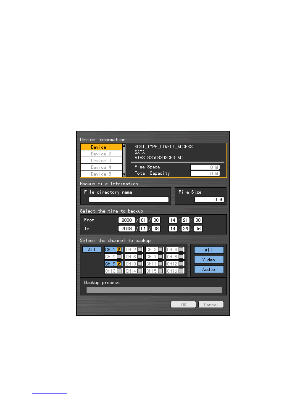
[Figure 4-12. Backup Window]
① Figure 4-12 shows the initial backup window menus.
② A list of devices that can be selected as well as simple information on the currently
selected devices are outputted.
③ Selecting a device by pressing the [SELECT] button causes the free space and total
45
capacity for the selected device to be displayed.
④ Selecting a device causes the directory name based on the initial values for the time
and channel to be displayed and the size of the file to be backed up to be calculated.
⑤ The directory name is set up using the backup time. The first 12 digits are determined
by the year/month/date/hour/minute/second for From, and the 12 digits in the middle, by
the year/month/date/hour/minute/second for To. The last 2 digits are determined by the
number of folders in the selected device.
⑥ If a device is not selected, the backup time and channel cannot be changed.
⑦ Selecting a device enables selecting the backup time as well. As a rule, the From time
cannot be later than the To time, and the To time cannot be earlier than the From time.
⑧ Selecting the item to be changed for the year/month/date/hour/minute/second and
pressing the [Select] button will cause the values that can be set up to be displayed in
the Scroll Box. If no channel has been selected, however, the time cannot be changed
either.
※ The time displayed at this time means that there is data at the corresponding time. If there
is no data, however, the time is not included in the Scroll Box.
⑨ Changing the backup time causes the name of the directory to be backed up to be
changed as well.
⑩ To select the backup time, channel, or media, select {Menu} Æ {Channel}, {Menu} Æ
{Time}, or {Menu} Æ {Media}.
※ The channel to be backed up can only be selected if there is data within the selected time.
⑪ If the file to be backed up exceeds the free space, its size is displayed in a yellow box in
case the selected device is capable of rerecording and in a red box if not.
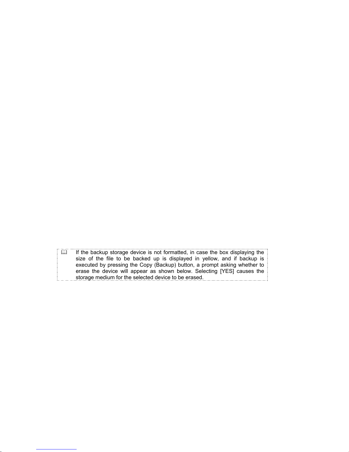
If the backup storage device is not formatted, in case the box displaying the
size of the file to be backed up is displayed in yellow, and if backup is
executed by pressing the Copy (Backup) button, a prompt asking whether to
erase the device will appear as shown below. Selecting [YES] causes the
storage medium for the selected device to be erased.
⑫ Press the Copy (Backup) button. A prompt asking whether to proceed with the backup
or not will then be displayed.
※ Select [Yes] to back up the data or [No] to stop the backup. Otherwise, press the [Cancel]
button to return to device selection mode on the backup window.
⑬ Select {Yes} to continue the backup.

46
4-13 Snapshot
The Snapshot function lets the user create a JPG file in real-time monitoring, playback, search,
or log mode and back up the image data.
① To back up the currently displayed image, select {Live Menu} Æ {Copy} Æ {Snapshot}
in real-time monitoring mode or {Playback Menu} Æ {Copy} Æ {Snapshot} in
Playback mode.
② When a USB2.0 backup device (excluding ODD devices) is searched, the JPG file is
stored in the same device.
③ If there are no or more than two USB2.0 storage devices (excluding ODD devices), a
window for selecting the device will be displayed.
④ If the selected device is an ODD device, a prompt asking whether to back up the ODD
device will be displayed.
4-14 Print
In real-time monitoring, playback, or log mode, the user can print the currently displayed image
using the Print function.
① To print the displayed image, select {Live Menu} Æ {Copy} Æ {Print} in real-time
monitoring mode or {Playback Menu} ( {Copy} ( {Print} in Playback or Log mode.
The Print function can be used only with a USB※ -type Printer supporting the Post Script (PS).
4-15 PTZ Camera Control
4-15-1 Conditions for Using the PTZ Features
① The PTZ camera must be connected to the system.
② Select {Additional Setup} -> {PTZ Setup} and check whether the PTZ camera setting
is appropriate.
※ For more information on the PTZ camera setting, select {Additional Setup} -> {PTZ Setup}.

47
4-15-2 Shifting to PTZ Mode
① In real-time monitoring mode, select {Live Menu} Æ {PTZ}.
② As shown in Figure 4-13, an icon will be displayed on the channel with a PTZ camera
installed.
[Figure 4-13. Initial Screen in PTZ Mode]
Channel Selection Window
Activation
mode
The channel selection window can be moved, and the channel screen
border is highlighted in orange.
Selection
mode
The channel is selected, and the channel screen border is highlighted
in blue.
4-15-3 PTZ Control
1) Horizontal/Vertical rotation
① Select a PTZ camera using the arrow keys and the Select button.
② The PTZ control window will then appear.
③ Move horizontally or vertically using the arrow keys.
④ To shift to screen split mode, select {Menu} {Display Setting} and screen split mode.
2) Zoom in/Zoom out
① To shift to Zoom In/Out mode, press the PTZ button in vertical/horizontal PTZ rotation
mode.
② The user can zoom in or out images using the arrow keys.
③ To change the screen split in Zoom In/Out mode, select {Menu} Æ {Display Setting}
and screen split mode.
48
3) Focus Control
① To shift to focus control mode, press the PTZ button again in PTZ Zoom In/Out mode.
② Use the arrow (▲▼) buttons.
③ To change the screen split in focus control mode, select {Menu} Æ {Display Setting}
and shift to screen split mode.
4) Preset
Used to store the horizontal/vertical/extended/focus settings of the PTZ camera
① To shift to Preset mode, press the Select button in Horizontal/Vertical PTZ Rotation,
Zoom In/Out, or Focus Control mode.
② In PTZ Preset mode, select the Preset mode using the arrow keys and the Select button.
③ Numbers between 1 and 8 can be assigned.
④ After presetting is completed, the set numbers are displayed in blue, and the PTZ
setting status with the set number will be stored.
5) Using the Preset Function
In Vertical/Horizontal PTZ rotation, Zoom In/Out, and Focus Control modes, use the
numeric buttons.
6) Using the Tour feature
※ For more information on setting the Tour feature, select {Additional Setup} -> {PTZ Setup}
-> {Tour}.
① After the Tour is set, No. 9 or No. 0 will be displayed in blue.
② In Vertical/Horizontal PTZ Rotation, Zoom In/Out, or Focus Control mode, use the
numeric button 9 or 0.
③ To disable the Tour feature, press the currently enabled Tour numbers (9 and 0).
Tour 1
Set to 9.
Tour 2
Set to 0.
7) Controlling the PTZ Speed
① Adjust the PTZ speed using the Up/Down button.
② Speed is set between 1 ~ maximum speed.
③ The maximum speed differs for each PTZ model.

49
Chapter 5. System Setup
5-1 Main Setup
{Main Setup} is used to set the recording, system environment, and other major features.
5-1-1 Starting the Main Setup
① On the real-time monitoring screen, select {Live Menu} Æ {Main Setup}.
② The Main Setup window will then appear as shown in Figure 5-1.
5-1-2 Data Selection (Data 1 ~ Data 4)
① On the Main Setup window, select data using the arrow keys (up to four data types are
supported).

50
5-1-3 Shifting to Recording Setup Mode
{Recording Setup} supports two modes: data mode and channel mode.
On the Recording Setup window, select {Menu} {Convert}. Two modes will be available.
1) Data Mode
This is a method of setting up the data for Channel Nos. 1 ~ 16 based on the data profile of
Data 1 ~ Data 4 as shown in Figure 5-1.
[Figure 5-1. Main Setup Window (Data Mode)]
2) Channel Mode
This is a method of setting up the data for Channel Nos. 1 ~ 16 based on four channel groups
as shown in Figure 5-2.

51
[Figure 5-2. Main Setup Window (Channel Mode)]
5-1-4 Saving the Recording Setting
① To save the new setting, select {Save} using the arrow keys and the Select button.
② To save a new setting as new data, select {Save As}.
③ On the selection window, select the desired data using the arrow keys and the Select
button.
④ Exiting without saving the changes causes a prompt asking whether to save the new
setting or not to be displayed.
⑤ Select {Yes} to save the changes.
※ To apply the new setting, the user should save the new setting.
5-1-5 Recording Setup
1) Camera Channel
(1) Title
Used to name each camera channel

52
① Select {Name} for the camera channel using the arrow keys and the Select button.
② On the selection window, select the first row and enter the name of the camera channel.
(2) Covert
Used to hide the channel video on the real-time monitoring screen
③ Select {Name} for the camera channel using the arrow keys and the Select button.
④ On the selection window, select the second row and decide whether to hide or display
the camera channel.
※ Video data are saved on the real-time monitoring screen even though they are not
displayed.
(3) Connection
Used to set whether to connect or disconnect each camera channel
① Select {Name} for the camera channel using the arrow keys and the Select button.
② On the selection window, select the third row and decide whether to connect or
disconnect the camera channel.
※ When the camera channel is set to disconnected, the video contents will not be displayed
even if the camera is actually connected.
2) Recording
Used to set the resolution, recording quality, recording type, recording frame, and audio
recording status
(1) Resolution
Used to set the resolution of the recorded channel
① Select {Recording} Æ {Res.} for the channel using the arrow keys and the Select
button.
② On the selection window, select the Resolution.
To set all channels at the same time, go to the top of the (Resolution) column and press
the [Select] button.
Resolution by Video Type
Type
Resolution
NTSC PAL
CIF 352 240ⅹ 352 288ⅹ
Field 704 240ⅹ 704 288ⅹ
Full 704 480ⅹ 704 576ⅹ

53
(2) Quality
Used to set the quality of the recorded video
① Select {Recording} (Qual.) for the channel using the arrow keys and the Select
button.
② On the selection window, select the recording quality.
The bigger the file size is, the higher the resolution.※
To set all channels at the same time, go to (Quality) on top of the column and press the
[Select] button.
(3) Mode
Used to set the recording type for the channel
① Select {Recording} {Mode} for the channel using the arrow keys and the Select
button.
② On the selection window, select the recording mode.
Recording
Type
Description
Automatic
Set the event recording speed and normal recording speed separately.
Recording is carried out by automatically selecting the recording mode
based on each setup value.
Continuous
Continuous recording is done based on the normal frame value.
Motion
Recording is done based on the event frame setting in case motion is
detected.
Sensor
If input signal is generated from an external sensor, recording is done
based on the event frame setting.
Sound
When sound is detected, recording will be done based on the event
frame value.
Recording Conditions
Recording
Type
Setting
Continuous
{Record} Æ {Rate} Æ Normal: 1~30
Motion
{Event} Æ {Motion}: Part or All
{Record}Æ{Rate}Æ
Event: 1~30
Sensor
{Event} Æ {Sensor}: 1~16
Sound
{Event} Æ {Sound}:1~16
Automatic
Enables setting both Normal and Event simultaneously
To set all channels at the same time, go to the top of the {Mode} column and press the Select
button.
(4) Frame Rate
Depending on the recording mode, the recording frame can be divided into the Normal type
and Event type.

54
Normal
Sets the recording frame rate for Automatic and Continuous
recording
Event Sets the recording frame rate for Automatic, Motion, Sensor,
and Sound recording
Maximum Recording Frame by Resolution
Resolution
Model
CIF (352 240)ⅹ Field (704 240)ⅹ Full (704 480)ⅹ
MV-1648
480fps 240fps 120fps
MV-824/424
240fps 120fps 60fps
① Select {Recording} {Rate} for the channel using the arrow keys and the Select
button.
② On the selection window, select the frame rate.
③ In adjusting the frame rate, setting the frame rate to be higher than the maximum frame
rate causes a menu to be displayed as shown in Figure 5-3.
④ The yellow-colored channel is currently being set as shown in Figure 5-3. Any unused
channel will be deleted first.
[Figure 5-3. Frame Rate Setting Window]
To set all channels at the same time, go to the top of the {Rate} column and press the
Select button.

55
(5) Audio
Used to set the recording for the external audio input linked to the system
① Select {Recording} {Audio} for the channel using the arrow keys and the Select
button.
② On the selection window, select whether to record audio or not.
To set all channels at the same time, go to the top of the {Audio} column and press the
Select button.
3) Event
(1) Motion
This function detects the movement of images. Detection settings include All, Part, and Off.
The default value is Off, however.
Full
Detects all movements of images in each channel
① Select {Event} Æ {Moti.} for the channel using the arrow keys and the Select button.
② On the selection window, select All.
Partial
Motion is detected in the user-defined areas of an image only.
① Select {Event} Æ {Moti.} for the channel using the arrow keys and the Select button.
② On the selection window, select Partial.
③ The grid will then be displayed on the screen.
④ Select the area where motions will be detected using the arrow keys and the Select
button.
⑤ Select the zone and press the [ESC] button.
Method of Selecting the Zone
1) To view the zone set in yellow, press the [Select] button.
2) Set the zone using the arrow buttons and press the [Select] button.
3) Once set, the zone is displayed in green.
※The [Select] button supports toggling.
Off
Motion detection in the video is disabled.

56
Select the motion detection sensitivity.
① Select {Event} Æ {Moti.} Æ {Sensitivity} for the channel using the arrow keys and the
Menu button.
② On the selection window, select the sensitivity using the arrow keys and the Select
button.
To set all channels at the same time, go to the top of the {Motion} column and press the
Select button.
Method of Setting the Sensitivity
Current sensitivity levels -- Lowest/Low/Middle/High/Highest -- indicate the proportion
of pixels within a block for which motion was detected. Therefore, the higher the
selected level is, the faster the motion that can be detected.
(2) Sensor
This sets the detection of input made by external sensors interworking with the system. Up
to 16 external sensors can be set. When a signal of an external sensor is detected, the
video of the corresponding channel will be recorded.
① Select {Event} {Sens.} for the channel using the arrow keys and the Select button.
② On the selection window, select an external sensor channel using the arrow keys and
the Select button.
③ Select {Event} {Sens.} {Sensor Type} for the channel using the arrow keys and
the Menu button.
④ On the selection window, select the sensor type using the arrow keys and the Select
button.
To set all channels at the same time, go to the top of the {Sens} column and press the
Select button.
Normal Close (NC): Normally closed; opens when a signal is received
Normal Open (NO): Normally open; closes when a signal is received
(3) Sound
This detects sound inputted by an external source interworking with the system. Up to 16
audio inputs linked to the system may be set. If an external audio input signal is detected,
the video for the corresponding channel will be recorded. Each channel can detect 1 ~ 16
external audio devices.

57
① Select {Event} {Sound} for the channel using the arrow keys and the Select button.
② On the selection window, select an audio channel using the arrow keys and the Select
button.
③ Select {Event} {Sound} {Sensitivity} for the channel using the arrow keys and
the Menu button.
④ On the selection window, select audio sensitivity using the arrow keys and the Select
button.
To set all channels at the same time, go to the top of the {Sound} column and press
the [SELECT] button.
(4) Pre Alarm
Used to set the recording time after the occurrence of an event
① Select {Event} Æ {Post} for the channel using the arrow keys and the Select button.
② On the selection window, select the time value using the arrow keys and the Select
button.
Time is set in seconds. Whenever an event is detected, recording will be done for the set
time.
To set all channels to the same value at the same time, go to the top of the {Post} column
and press the [SELECT] button.
(5) Post Alarm
Used to set the recording time after the occurrence of an event
③ Select {Event} Æ {Post} for the channel using the arrow keys and the Select button.
④ On the selection window, select the time value using the arrow keys and the Select
button.
occurrence of an event
occurrence of an event

58
Time is set in seconds. Whenever an event is detected, recording will be done for the set
time.
To set all channels to the same value at the same time, go to the top of the {Post} column
and press the [SELECT] button.
4) Alarm Out
This feature is used to generate alarms through the buzzer, mail, spot monitor, or relay in case
of an event.
(1) Buzzer
This feature is used to run the buzzer in the product in case of an event.
① Select {Alarm Out} {Buz.} for the channel using the arrow keys and the Select
button.
② On the selection window, select the event subject to buzzer operation (e.g., movement,
sensor, sound) using the arrow keys and the Select button and decide whether to
activate or deactivate the buzzer. Multiple time zones may be selected.
59
(2) Preset
When an event occurs, the PTZ camera will be preset.
① Select {Alarm Out} Æ {PSet} for the channel using the arrow keys and the Select
button.
② On the selection window, select the event (sensor or sound) and decide whether to
generate an alarm or not using the arrow keys and the Select button.
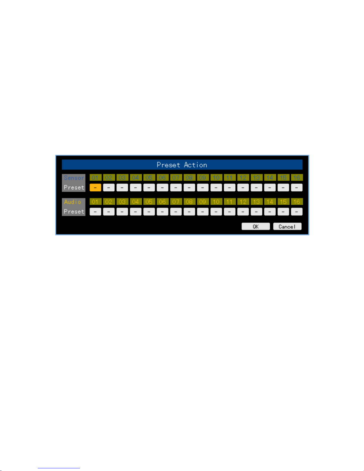
③ Select {Alarm Out} Æ {PSet} Æ {Preset Action} for the channel using the arrow keys
and the Menu button.
④ Assign a Preset for each event.
⑤ Select the OK button to save. Otherwise, select the cancel button and press the
[SELECT] button to cancel.
[Figure 5-4. Preset Action Setting Window]
To set all channels to the same value at the same time, go to the top of the {Preset}
column and press the [Select] button.
Preset can be set to 1 ~ 8.
(3) Email
When an alarm or an event occurs, emails will be sent to the specified email address.
① Select {Alarm Out} Æ {Mail} for the channel using the arrow keys and the Select button.
② On the selection window, select event types and decide whether to use the email
function or not using the arrow keys and the Select button.
The mail service can be set up in the {Additional Setup} {Network} {Alarm} menu.
(4) Spot
Displays the video on the TV monitor connected to the spot port on the rear side of the system
in case of an alarm or an event

60
① Select {Alarm Out} Æ {Spot} for the channel using the arrow keys and the Select
button.
② On the selection window, select the event type and decide whether to use the spot
function or not using the arrow keys and the Select button.
To set all channels at the same time, go to the top of the Spot column and press the
[Select] button.
(5) Relay
In case an alarm or an event occurs, all external alarm devices connected to the relay port will
be triggered.
① Select {Alarm Out} {Relay} for the channel using the arrow keys and the Select
button.
② On the selection window, select the event type and decide whether to use the Relay
function or not using the arrow keys and the Select button.
③ Select {Alarm Out} {Relay} {Relay Type} for the channel using the arrow keys
and the Menu button.
④ On the selection window, select the relay type using the arrow keys and the Select
button.
To set all channels at the same time, go to the top of the {Relay} column and press the
[Select] button.
5-1-6 Recording Schedule
{Recording Schedule} is used to save the system configuration as data from Data 1 to Data 4
and to make a recording based on the system configuration for each day/time zone.
[Figure 5-5. Recording Schedule Window]

61
1) Selecting the Recording Schedule Menu
① On the initial Main Setup screen shown in Figure 5-1, the user can select a recording
schedule using the arrow keys and the Select button.
② The initial recording schedule screen will then appear as shown in Figure 5-5.
2) Recording Schedule Setting
(1) Used to set each column
① Select the date and time to be set using the arrow keys.
② Select the data you want to set.
a) Pressing (or double-clicking) the Select button causes only the selected date and
time to be set.
b) Select (or right-click) the Menu button to make the setting for all time zones after the
selected date and the time zone.
③ On the selection window, set the data using the arrow keys and the Select button.
(2) Set each column.
① Go to the top of the time column using the arrow keys.
② Select the data you want to set.
a) Press (or double-click) the Select button to set only one column.
b) Select (or right-click) the Menu button to make the setting for all time zones after the
selected time zone.
③ On the selection window, set the data using the arrow keys and the Select button.
(3) Setting Holidays
This feature is used to enable the user to set the holidays.
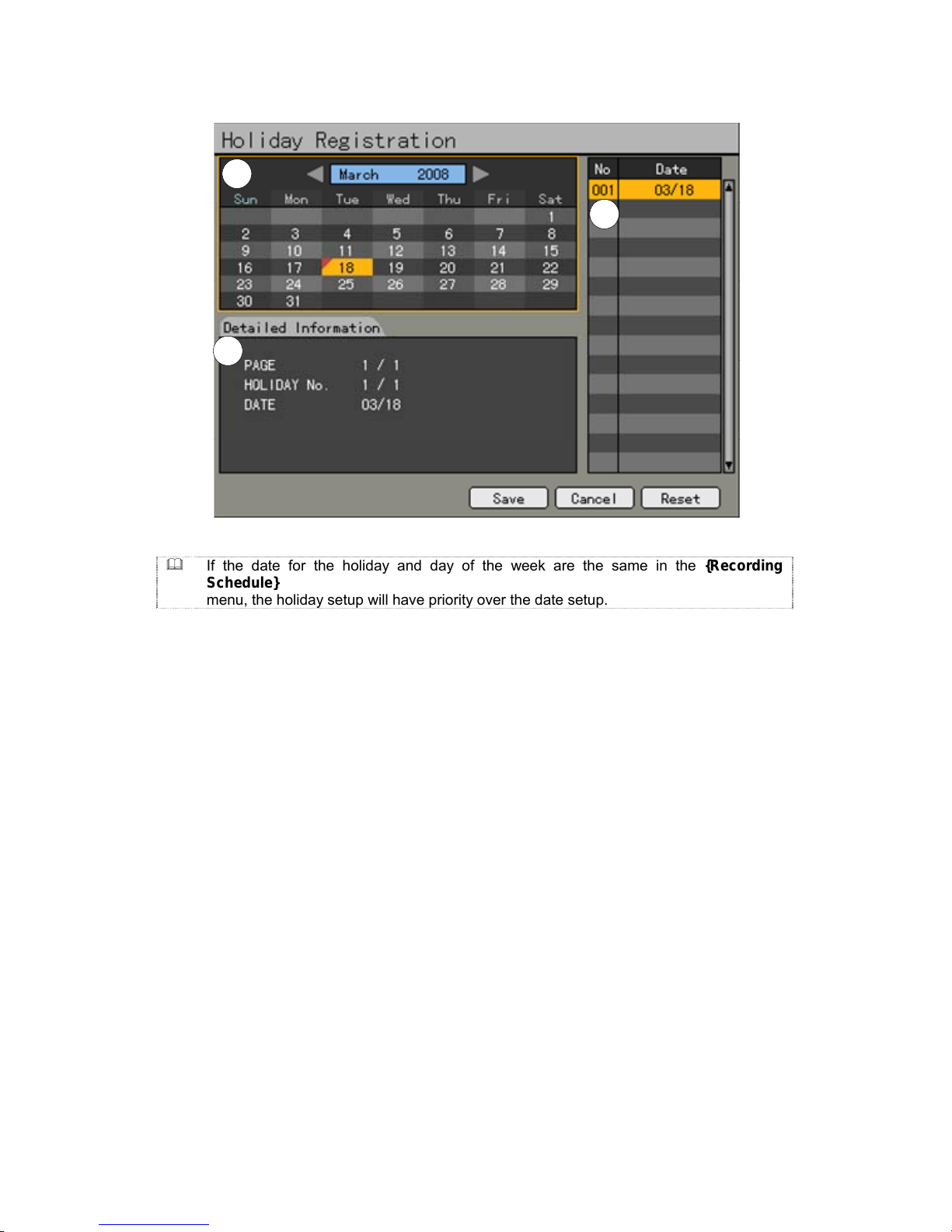
62
C
B
A
[Figure 5-6. Holiday Registration Window]
If the date for the holiday and day of the week are the same in the {Recording
Schedule}
menu, the holiday setup will have priority over the date setup.
Ⓐ Calendar
The defined holidays will be indicated with a red tag.
Ⓑ Holiday List
The list of all defined holidays will be displayed.
A total of 15 holidays will be displayed per page, and the rest, on the succeeding
pages.
Ⓒ Holiday Information
Detailed information for the selected date will be displayed.
{Page} shows the page count when there are more than 15 holidays
{Current page/Total page}.
{Holiday No.} denotes the holiday number arranged by date.
{Number of selected holidays/Total number of holidays}
{Date} shows the date of the holiday.
① Click the {Recording Schedule} menu and select {Menu} Æ {Holiday}.
② On the Holiday Registration window, select the date using the arrow button and the
Select button and press the Select button.
③ After setting the holiday, press the [ESC] button followed by the [Save] button at the
bottom of the menu. Afterward, press the [Select] button.
If the date for the holiday and day of the week are the same in the {Recording Schedule}
menu, the holiday setup will have priority over the date setup.

63
5-1-7 System
The system may be set up in the {System} menu as shown below; ditto for the auxiliary
features of the system.
1. {Local Administrator’s Password}
Used to set the password of the Local System
Administrator
2. {Automatic Menu Exit}
Used to set the time for exiting the System Setup
menu automatically and displaying the real-time
monitoring screen
3. {DVR Name}
Used to name the DVR device
4. {Remote Controller ID}
Used to name the remote controller for running
the system
5. {Time Display Type}
Used to set the date display format
6. {User Registration}
Used to register, add, or delete users
7. {Buzzer}
Used to turn the System Buzzer ON/OFF
8. {Set Alarm Time}
Used to set the alarm generation time (in
seconds)
9. {Upgrade}
Upgrades the system firmware
10. {Reset}
Used to execute reset
11. {PTZ Home Position Time}
Automatically executes Preset No. 1 of PTZ
12. {PTZ Control Type}
PTZ control method setting
13. {Language}
System language setting
14. {RS232C Port}
Use of the RS232C port
15. {System Controller ID}
Unique system controller number setting

64
1) Selecting the system menu
① On the initial Main Setup window shown in Figure 5-1, select the system using the arrow
keys and the Select button.
② The system configuration menu will then appear as shown in Figure 5-7.
[Figure 5-7. System Setup Window]
2) {Local Administrator’s Password}
① Select {Local Administrator’s Password} using the arrow keys and the Select button.
② On the password input window, enter a password using the numeric buttons of the
remote controller or the arrow keys and the Select button (the password can contain up
to five digits).
3) {Automatic Menu Exit}
If no input is made in the System Setup menu using the front buttons, remote controller, or
mouse, the system automatically shifts to real-time monitoring mode.
① Select {Automatically Exit Menu} using the arrow keys and the Select button.
② On the selection window, select the time zone you want to set using the arrow keys and
the Select button.
OFF
Automatic Menu Exit is not used.
※ The user can exit the menu by pressing the [ESC] button in the
System menu.
10/20/30
seconds
If there is no input using the front button, remote controller, or mouse,
the system will shift to real-time monitoring mode.
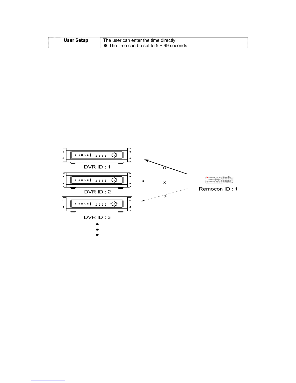
65
User Setup
The user can enter the time directly.
The time can be set to 5 ~ 99 seconds.※
③ Selecting User Setup causes the input window to appear as shown below.
④ Enter the time using the numeric buttons or the arrow keys and the Select button.
4) Rename DVR
① Select {DVR Name} using the arrow keys and the Select button.
② On the input window, enter a name using the numeric buttons or the arrow keys and the
Select button (the system name may contain up to 20 English characters).
5) Remote Controller ID
When multiple devices are used, set the remote controller ID to identify input signals from a
remote controller.
Only the system wherein the DVR ID and remote controller ID match can receive input
signals from the remote controller as shown below.
① Select {remote controller ID} using the arrow keys and the Select button.
② Enter the ID (between 0 and 99) using the numeric buttons or the arrow keys and the
Select button.
※ If you forgot the DVR ID, set the remote controller ID to 999 to start the DVR.
※ Note, however, that the DVR ID should be the same as the remote controller ID.

66
6) Changing the date format
① Select {Time Format} using the arrow keys and the Select button.
② On the selection window, select the date format using the arrow keys and the Select
button.
7) User Registration
Adds, edits, or deletes the users who will operate the system
System Use Requiring Authorization
Network Live
Enables viewing real-time images upon network
access
Play
Enables viewing the Recorded Screen
Copy (download)
Copies and downloads files
PTZ Control
PTZ camera control
Main/Additional Setup
Data setup, recording schedule, system, storage,
NTP, advanced setup, PTZ camera, network,
camera/TV setting
Network Upgrade
Remote network upgrade
V
iew Hidden Channel on Network
Enables viewing hidden channels on the network
(1) Edit User Information
① Select {Register User} Æ {Edit User} using the arrow keys and the Select button.
② On the selection window, select a user using the arrow keys and the Select button.
③ On the user authority setting window, set the user authority using the arrow keys and
the [Select] button as shown in Figure 5-8.
[Figure 5-8. User Authority Setup Window]

67
(2) Add User
① Select {Register User} Æ {Add User} using the arrow keys and the Select button.
② On the user registration window, enter the ID and the password. Up to four users can be
registered (the user ID and password may contain up to 30 English characters).
③ After entering the user ID and password, select the user authority using the arrow keys
and the [Select] button.
(3) Delete User
① Select {Register User} Æ {Delete User} using the arrow keys and the Select button.
② On the selection window, select the user you want to delete using the arrow keys and
the Select button.
8) Alarm Action
① Select {Alarm Action} using the arrow keys and the Select button.
② On the selection window, select whether to use this function or not using the arrow keys
and the Select button.
The {Reset Buzzer Setting} function starts the buzzer in case of HDD Fail, Backup
Fail, Network Fail, Fan Fail, Power Fail, or Signal loss.
9) Set Alarm Time
① Select {Set Alarm Time} using the arrow keys and the Select button.
② On the selection window, select the time for generating the alarm using the arrow keys
and the Select button.
10) Upgrade
The product can be easily upgraded through the use of an external storage device or a
portable storage device with USB 2.0 port or built-in CD-RW/DVD-RW.
① Find and copy the upgrade file to the highest folder in the external storage device or
portable storage device supporting USB 2.0.
1)
2)
3)
When copying an upgrade file from the PC, delete the USB device
properly from the PC and disconnect it from the USB port.
If the USB device is disconnected from the USB port while the upgrade
file is being copied, the DVR system may not automatically detect the
file.
Upgrading is impossible if the HDD is not mounted.
68
① Connect the storage device with an upgrade file stored in the USB 2.0 port at the back.
② Select {Upgrade} using the arrow keys and the Select button.
③ The upgrade file list stored in the selected device and simple version information for the
selected file are then displayed.
④ After selecting the file to be upgraded, press the [SELECT] button.
※ Downgrading to a previous version is not supported.
※ The upgrade information window will then appear within 15 seconds.
Read the information and select {Yes} to start the upgrade gradually. Select {No} to return to
{System} mode.
⑤ After the update is completed, the system will be rebooted.
⑥ The system will automatically start. Upgrade is then completed.
⑦ Select {Status} Æ {Product Information} Æ {Software Version}.
11) Reset All Setting
① Select {Reset All Setting} using the arrow keys and the Select button.
② When prompted whether to reset all setting, select Yes.
Note that all setting data will be reset.
※ The factory setting will be restored.
12) PTZ Home Position Time
This feature enables Preset1 to be executed automatically for the corresponding PTZ if no
control occurs for a specific amount of time after controlling the PTZ. Preset 1 replaces the
Home Position feature.
① Select {PTZ Home Position Time} using the arrow keys and the Select button.
② On the selection window, select the time using the arrow keys and the Select button.
13) PTZ Control Type
① Select {PTZ Control Type} using the arrow keys and the Select button.
② On the selection window, select the type using the arrow keys and the Select button.
A
-Type
This is a method wherein the corresponding command
(Pan/Tilt/Zoom/Focus) is sent in case of key input; a Stop command
is not sent pending another key input.
B-Type
In case of key input, the corresponding command
(Pan/Tilt/Zoom/Focus) is sent. In the absence of another key input
within a specific time (about 0.5 second), the Stop command is sent.

69
14) Language
This feature is used to select the language for the On Screen Display (OSD) menu of the
system.
① Select {Language} using the arrow keys and the Select button.
② On the selection window, select the language using the arrow keys and the Select
button.
15) RS232C Port
① Select {RS232C Port} using the arrow keys and the Select button.
② On the selection window, select the device using the arrow keys and the Select button.
16) System Controller ID
① Select {System Controller ID} using the arrow keys and the Select button.
② On the input window, enter the ID (between 1 and 255) using the numeric buttons or
arrow keys and Select button.
17) Save
After changing the setting in the {System} menu, save the changes.
① After completing the system setting, select {Menu} Æ {Save}.

70
5-1-8 Storage
1) Selecting the Storage Menu
① Select the {Main Setup} and {Storage} menus.
[Figure 5-9. Storage Window (Local)]
2) Local
(1) Selecting the Local Menu
① Select the Storage and Local menus using the arrow keys and the Select button.
To apply the new setting, save the new setting.
Reload: Used to read the local storage device management information again
Save: Saves the setting data
Cancel: Exits without saving the setting
Reset: Deletes the previous settings and initializes the setup
(2) HDD Overwrite
This feature is used to overwrite on the HDD.

71
① Select {HDD Overwrite} using the arrow keys and the Select button.
② On the input window, select whether to use this function or not using the arrow keys and
the Select button.
ON
If there is no more hard disk space left, the existing files will be overwritten
starting with the oldest.
OFF
If the hard disk space has been used up, further recording will not be
executed.
(3) Selecting the Manage Local Storage Menu
① Select {Manage Local Storage} using the arrow keys and the Select button.
② Local storage types include {Direct}, {Backup}, and {New}.
(4) Maintenance of the local storage device
A local storage refers to the internal hard disk, USB, and other devices connected to the
IEEE1394 port. Local storage types include {New}, {Direct}, and {Backup}. The functions are
as follows:
① New
The administrator manages all initially detected storages. All initially detected storages are
displayed as New and can be changed into Storage or Backup.
{Direct Initialize}: Changes the selected storage into a dedicated direct storage
{Backup Initialize}: Changes the selected storage into a backup storage
{New} At least one storage shall be selected as a dedicated storage.
Otherwise, the data cannot be stored in real time.

72
② Direct
The administrator manages dedicated (or direct) storages. A dedicated (direct) storage
stores data on the hard disk in real time. Five commands can be executed. Depending on
the S/W status, however, some commands cannot be executed.
{NEW}: Returns the status of the selected storage device to New; if this command is
executed, the selected storage device will be moved to the {New} storage device
manager
{Online}: Changes the selected storage device in online state
{Offline}: Changes the selected storage device in offline state
{Format}: Formats the selected storage
{Eject}: Separates the selected device completely from the software
※ Physical states supporting the execution of the commands above include Healthy and
Warning. In fault state, however, no command can be executed.
When removing a device installed in the DVR, USB, or storage connected to
the IEEE1394 port, the user shall execute the {Eject} command.
③ Backup
The administrator manages backup storages. Backup storages are not used to store data;
rather, they are only used to back up data. The user can execute only the {New} command.
Depending on the storage type, the storage is used only for direct or backup
purposes.
(5) Configuration of the local storage device
① {Model}: Model name of the storage device
② {Serial}: Serial number of the storage device
③ {Location}: Physical location of the storage device
④ {Capacity (T/F)}: Storage device capacity (T: Total; F: Free)
⑤ {Status (SW/HW)}: Storage device status (SW: Software; HW: Hardware)
※ There are three software status types:

73
Active: Connected to storage or backup device; currently saving the data
Online: Only connected to storage or backup device
Offline: Not connected to storage or backup device
※ There are three hardware status types:
Healthy: Connected to storage or backup device; functions normally
Warning: Connected to storage or backup device, but error was detected; in this
case, data storing or backup cannot be made (for more information, see
the description below).
Fault: Not connected to storage or backup device; cannot perform data saving
or backup
1. Fault state: The storage device is completely damaged, and none of the S/W
operations can be performed. The fault state is not related to a DVR problem.
The DVR has detected the fault and stopped the recording.
2. Warning state: The storage device has a physical error that can be
corrected by the storage device or by the DVR. If the error is not taken care
of, however, the storage device is likely to be damaged (and shift to fault
state). Backing up data in the corresponding storage device and replacing the
device with a normal one are strongly recommended.
3. If there is an active storage device with a warning or a fault, a message is
displayed on the upper left part of the screen. If the user checks the {Log},
the DVR will assume that the problem has been taken care of and will stop
displaying the message.

74
(6) Operation after adding a local storage device
① Open the system body and install a new disk (connect the data cable and the power
cable).
② Connect power to the system and boot the system.
③ Select {Main Setup} ( {Storage} ( {Local} using the arrow keys and the Select button.
④ A newly displayed disk will then be displayed as {New}.
⑤ Select a newly installed disk using the arrow keys and the Select button and initialize
the disk as a {Direct} or a {Backup} disk. The following describes the method of setting
a direct storage:
⑥ {Direct} shows the status of the newly installed disk online.
(7) Operation of the local storage device
① From the Manage Local Storage menu, select {Direct}, {Backup}, and {New} using the
arrow keys.
② If there is a valid storage device in the corresponding tab, the desired storage device
may be selected using the arrow buttons.
③ Select the storage using the Select button. Popup menus will then be displayed.
④ Select menus using the arrow keys and the Select button.
※Selecting {Direct-Init} or {Backup-Init} may cause all data in the device
to be damaged. Therefore, caution is required.
※While {Direct-Init} or {Backup-Init} is being set up, do not remove the
device (may cause an error when detecting the device).
※To use the external or portable storage device for system upgrade, set
to {Backup-Init} in the {New} item for {Main Setup} {Storage Device}
{Local Storage Device Management}.
※When used in DVR equipment for the first time, a backup USB device
will always be detected in the {New} category. Therefore, a USB device in
the {New} category must be set up as {Backup-Init} prior to use for
backup. A USB device that has gone through this procedure will be
detected in the {Backup} category when used again in the DVR
equipment.

75
2) NAS Backup
(1) Selecting the NAS Backup Menu
① Select {Main Setup} Æ {Storage} Æ {NAS Backup}.
[Figure 5-10. Storage Window (NAS Backup)]
(2) Using NAS
① Select {Use NAS} using the arrow keys and the Select button.
② On the selection window, select whether to use NAS or not using the arrow keys and
the Select button.
(3) ID and Password
ID and passwords are fixed values (cannot be modified).

76
(4) IP
① Select {IP} using the arrow keys and the Select button.
② On the input window, enter the IP using the arrow keys and the Select button.
(5) Directory
① Select {Directory} using the arrow keys and the Select button.
② On the input window, enter the directory using the arrow keys and the Select button.
(6) Execution time
① Select {Execution Time (Hourly)} using the arrow keys and the Select button.
② On the input window, enter the execution time between 1 and 59 using the arrow keys
and the Select button.
(7) Maximum storing time
① Select {Maximum Storing Time} using the arrow keys and the Select button.
② On the selection window, select One Hour or Two Hours using the arrow keys and the
Select button.
(8) Minimum space
① Select {Minimum Space} using the arrow keys and the Select button.
② On the input window, enter the minimum space between 10 and 100 (GB) using the
arrow keys and the Select button.
(9) Overwrite
This feature activates/deactivates NAS overwriting.
① Select {Overwrite} using the arrow keys and the Select button.
② On the selection window, select whether to use this function or not using the arrow keys
and the Select button.
5-1-9 NTP
This is the protocol for synchronizing the time between the devices connected through the
network or GPS.

77
※ Description of features
1. Time synchronization
1) Synchronization with the GPS server
The time is automatically synchronized every hour with the GPS Server.
2) Synchronization with the NTP Server
Time is synchronized with the NTP server every hour.
A. Automatic Setup
The nearest server from the user’s zone will be selected for connection. If the connection
fails, the next nearest server will be chosen.
B. User Setup
The user sets the URL or IP for the NTP server. If connection is not established, a message
will be sent to the user, and the related log, saved.
If synchronization with the NTP server fails, synchronization with RTC will be established.
3) Synchronization with the DVR Time Server
The DTS server is executed in the MV series; time is synchronized every hour. MV series
DTS clients referring to the DTS synchronize the time of the DVR system operating with
DTS.
When the DTS time or a zone is changed, the change is reflected on the MV series
belonging to the network (the synchronization signals are broadcasted without passing
through the router or gateway). The DVR time server does not support automatic connection.
2. Daylight saving time (DST) setup
Regardless of whether GPS, NTP server, or DST server is referred to, DST is automatically
processed according to the time.
3. User time setup
The user can set the time directly.
For the NTP client setup, the user can read the time but not change it.

78
1) Selecting the NTP Menu
① Select {Main Setup} and {NTP}.
[Figure 5-11. NTP Setup Window]
2) Time Server
① Select {Time Server} using the arrow keys and the Select button.
② On the selection window, select Time Server using the arrow keys and the Select button.
※
OFF
The time server is not used.
NTP
NTP is used to set the time for the time DVR.
GPS
GPS is used to set the time for the time DVR.
Select {Main Setup} Æ {System} Æ {RS232C Port}
GPS Timer.
3) NTP
When {Time Server} is NTP, the user can set {NTP}.
(1) Server type setup
① Select {Server Type} using the arrow keys and the Select button.
② In the selection box, select the server type using the arrow keys and the [Select] button.

79
(2) Server URL
① Select {Server URL} using the arrow keys and the Select button.
② In the selection box, select the server URL using the arrow keys and the [Select] button.
③ The user can enter the IP only when the server type is DVR. For the NTP server,
Automatic, IP, or URL should be selected.
4) GPS Reception Status
The reception state can be checked when {Time Server} is GPS.
※
Password (OK)
Satisfactory reception state
Not Good (NG)
Unsatisfactory reception state
5) Changing the system date and time
The user can change the system date and time only when the time server is off.
The system date and time format is Year/Month/Day Hour/Minute/Second. To set the display
format, select {Main Setup} -> {System} -> {Time Display Format}.

80
① Using the arrow keys and the Select button, 하여 {Date and Time}을 선택합니다.
② Select the field you want to change using the arrow buttons and press the [Select]
button.
③ After changing the date and time using the arrow buttons, press the [Select] button.

81
6) Standard Time Zone
① Select {Standard Time Zone} using the arrow keys and the Select button.
② On the selection window, select the standard time zone you want to set.
7) Daylight Saving Zone (Summer Time)
① Select {Daylight Saving Zone} using the arrow keys and the Select button.
② On the selection window, select whether to use this function or not using the arrow keys
and the Select button.
(1) Start Time
① Select {Start Time} using the arrow keys and the Select button.
② On the selection window, select the start time using the arrow keys and the Select
button.
(2) End Time
① Select {End Time} using the arrow keys and the Select button.
② On the selection window, select the end time using the arrow keys and the Select button.
※ For a weekly setting in the {Start Time} and {End Time} fields, set Day to 0.
※ After the DST is selected, the existing data will be displayed as “OLD_” in the search and
log list.

82
5-1-10 Advanced
This menu is used to set the video quality in detail for each channel.
1) Selecting the advanced menu
① Select {Main Setup} and {Advanced}.
[Figure 5-12. Advanced Setup Window]
2) Comb/Trap
① Select {Comb/Trap} for the channel using the arrow keys and the Select button.
② On the selection window, select a filter to be set up.
3) Maximum Bitrate
① Select {Maximum Bitrate} for the channel using the arrow keys and the Select button.
② On the input window, enter the maximum bitrate.

83
4) Peaking
① Select {Peaking} for the channel using the arrow keys and the Select button.
② On the selection window, select the peaking data you want to set.
5) Deinterlace
① Select {Deinterlace} for the channel using the arrow keys and the Select button.
② On the selection window, select whether to use this function or not.
6) Cording
① Select {Cording} for the channel using the arrow keys and the Select button.
② On the selection window, select whether to use this function or not.
※ Advanced Options
Menu Description
Comb/Trap
The Comb filter improves the resolution for brightness. It is
used when the boundary between brightness and color is not
clear. The Trap filter adjusts the definition of an image.
{Maximum Bitrate}
This is the largest unit for streaming moving images.
{Peaking}
Peaking is used to emphasize the edge of the Y elements.
The user can select No, 31%, 62%, or 93%. At 93%,
however, emphasis is highest for the edges. The default
value is 31%.
{Deinterlace}
This feature is designed to eliminate the horizontal lines
(shadows) in an image. It is applied only when full resolution
is used. The default value is ON.
{Cording}
Cording is a filter that flattens the edges of the Y
components in an image. It can be set to ON or OFF.
Selecting ON enables a soft image to be obtained. The
default value is OFF. Like Average Filter, Cording gives
similar results.

84
5-2 Additional Setup
Additional Setup includes the PTZ setting and network setting.
5-2-1 Selecting the Additional Setup Menu
① On the real-time monitoring screen, select {Live Menu} {Additional Setup}.
② The Additional Setup window will then appear as shown in Figure 5-13.
[Figure 5-13. PTZ Setup Window]
5-2-2 PTZ setup
Used to set the PTZ camera connected to the system
Menu CH
Displays Channel Nos. 1 ~ 16
Menu PTZ
Setting up the PTZ causing a camera icon to be displayed
Camera Title
Title for each channel
PTZ Protocol
Sets the protocol for communicating with the PTZ camera
Camera ID
ID set up in the PTZ camera
Transmission
Type
Type of control cable used to control the camera (RS-485)
Transmission
Rate
Communication speed (must be the same as that defined in the
camera manual)
Preset
Maintenance Time
Time interval required to change to the assigned screen between the
Preset defined in the Tour feature and the next Preset (5 ~60 seconds)
Tour
Sets the Tour feature (Tour 1 and Tour 2)

85
1) PTZ Protocol Setting
PTZ protocol refers to the rule for communicating with the PTZ camera.
① From the PTZ Setup menu, select the PTZ protocol for the channel you want to set
using the arrow keys and the Select button.
② On the selection window, select the PTZ protocol using the arrow keys and the Select
button.
2) Camera ID setup
Camera ID refers to the address used for communicating with the PTZ camera.
※ The camera ID must be the same as the ID set in the PTZ camera.
※ Different methods are used to set the address of the PTZ camera depending
on the camera manufacturer or model. Refer to the camera manual of each
manufacturer for the correct information.
① From the PTZ Setup menu, select the camera ID for the channel using the arrow keys
and the Select button.
② In the selection box, select the camera ID using the arrow keys and the [Select] button.
3) Setting the transmission rate
The transmission rate refers to the speed of communication with the PTZ camera.
※ The transmission rate must be the same as the communication speed of the
PTZ camera.
※ The transmission rates and setup methods for PTZ cameras vary by camera
manufacturer or model. Refer to the camera manual for details.
① From the PTZ Setup menu, select the transmission rate for the channel using the arrow
keys and the Select button.
② On the selection window, select the transmission speed using the arrow keys and the
Select button.

86
4) Preset Time setting
Tour interval time (select between 5 and 60 seconds)
① From the Preset Setup menu, select the preset time for the channel using the arrow
keys and the Select button.
② In the selection box, set the preset maintenance time using the arrow keys and the
[Select] button.
5) Tour Setup
Automatically controls the preset PTZ camera according to the predefined order
① From the PTZ Setup menu, select the Tour for the channel using the arrow keys and the
Select button.
② On the selection window, set Tour using the arrow keys and the Select button.
※Tour 1 is set to 9, and Tour 2, to 0.
5-2-3 Network setup
Used to set the system network
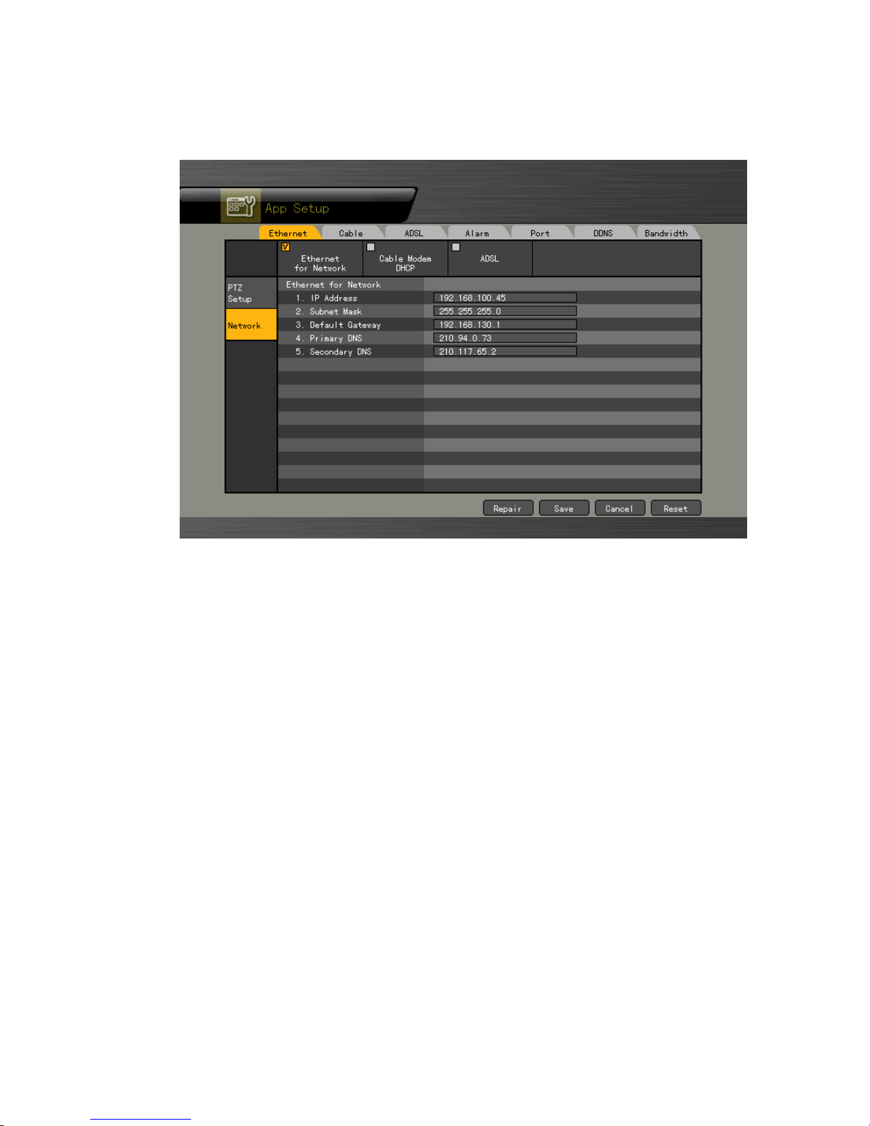
87
1) Selecting the Network Setup Menu
① In {Additional Setup} mode, select {Network} using the arrow keys.
[Figure 5-14. Network Setup Window]
2) Ethernet
Setup is performed to use a fixed IP in the local area network environment.
① From the Network Setup menu, select {Ethernet} using the arrow keys and the Select
button.
② Enter the IP address, subnet mask, default gateway, default DNS, and auxiliary DNS
using the arrow keys, numeric buttons, and Select button.
③ Set and store an Ethernet network using the arrow keys and the Select button.
3) Cable
Setup is executed to use the automatic access ADSL or a dynamic IP.
① From the Network Setup menu, select {Cable} using the arrow keys and the Select
button.
② Set as Cable Modem DHCP using the arrow keys and the Select button.
4) ADSL
This feature is used in the user authentication-type ADSL communication environment.

88
① From the Network Setup menu, select {ADSL} using the arrow keys and the Select
button.
② Enter the user account (ID) and password using the arrow keys and the Select button.
③ Set the ADSL and save the setting using the arrow keys and the Select button.
5) Alarm
This is set up for mail Alarm Out in case of an event.
To use this feature, the Call or Mail Alarm must be turned ON in {Main Setup} {Data Setup}.
① From the Network Setup menu, select {Alarm} using the arrow keys and the Select
button.
② Enter the telephone number and mailing addresses using the arrow keys and the Select
button.
6) Ports
This feature is used to set up the user for the network port.
The default value is between 2000 and 2007; a randomly chosen value can be used
depending on the network environment, e.g., firewall.
The Web Server Port is used to connect the DVR monitor. The default value is 80 (a random
number may also be used, however).
① From the Network Setup menu, select {Port} using the arrow keys and the Select button.
② Enter the port number and save it using the arrow keys and the Select button.
7) DDNS
As part of the DNS system, the Dynamic Domain Name System (DDNS) service updates the
IP addresses of host names in real time and allocates fixed domain names to systems linked
to dynamic IP addresses to allow users to use the same DNS name regardless of the changes
in the IP address.
The MV series provides dynamic DNS to ensure URL access in the dynamic IP environment.
① Equipped with web server functions, the MV series supports remote video monitoring.
From the Network Setup menu, select {DDNS} using the arrow keys and the Select
button.
② Enter the DDNS function status, domains registered in the server, DDNS password,
server IP address, and default port using the arrow keys and the Select button.
※ After accessing the DDNS Server (http://www.rifatron.net
), register the domain
name and enter a unique URL.
For more information on domain registration, refer to the DDNS manual.
※ The default IP address of the DDNS server is 211.117.45.25.
※ The default port of the DDNS server is 9100.
8) Bandwidth
Setup is performed to adjust the resolution, video quality, and frame speed of an image when
monitoring a live image using the network.
① From the Network Setup menu, select {Bandwidth} using the arrow keys and the
Select button.
② Set the lower items using the arrow keys and the Select button.

89
Apply temporal filte
r
Removes noises from the image and improves the compression
rate; the higher the compression rate, the faster the network
speed (a high compression rate may compromise the video
quality, however)
Image resolution
Controls the video resolution; the lower the resolution, the faster
the network speed (a low resolution rate may compromise the
video quality, however)
Image quality
Adjusts the video quality; the higher the image quality, the lower
the compression rate (a low compression rate may lower the
transmission speed, however)
Image transmission
rate
Controls the frame rate; the frame rate for 30 frames is as follows:
High: 30; Middle: 15; Low: 7.5

90
A/P/P/E/N/D/I/X
1. PTZ Camera Protocol
NO
V
endo
r
Protocol
1 A.D. SENSORMATIC
2 CHOU COHU
3 Dongyang DRX-500
4 EYE VIEW EYE VIEW
5 GE KARATEL
6 GSP CYBERSCAN_1
7 Hitron FASTRAX2
8 HONEYWELL HSDN-251
9 LG MULTIX, OLD
10 MIKAMI MIKAMI
11 Panasonic WVCS854
12 PELCO PELCO – D, PELCO - P
13 PHILIPS PHILIPS
14 PROLINE UK
15 RIFATRON RIFATRON
16 SAMSUNG TECHWIN SPD-1600, SCC641
17 VICON VICON
18 YOKO YOKO
2. Recommended HDD
NO Size Model Capacity
Buffer
RPM
1
3.5’’ 1.2 Flat Suport
WD Caviar SE 320GB 320GB 8MB 7200
3. Recommended USB2.0 Device
USB2.0 Device Media File System
Memory Stick Flash Type FAT32
2.5’’ Portable USB HDD HDD Type FAT32
CD CD R, R/W ISO9660
DVD DVD +R, +R/W ISO9660
DAT DDS-3, DDS-4, DDS-5 tar

91
4. Memory Stick
No.
V
endo
r
Model Capacity
1 Transcend Ultra Speed JetFlash 256MB
2 FM semiconductor MemoRive USB2.0 256MB
3 LG Xtick USB Drive 256MB
4 AL Tech ANYDRIVE mini USB 256MB
5 Kingston DataTraveler USB FLASH DRIVE 256MB
6 Sarotech FLEX FD-03U1 128MB
8 Sandisk Cruzer Mini 128M
10 Samsung PLEOMAX 128MB
11 Sony Micro Vault 128M
12 Sandisk U3 512M
5. 2.5’’ Potable USB HDD
No.
V
endo
r
Model Capacity
1 IT Mall neo Q Plus USB 2.0 20GB
2 USBNET Anypak USB 2.0 20GB 20GB
6. CD-RW, DVD-RW
V
endor Model Type
SONY DRX-810UL USB
Plextor PX-716UF USB
IEEE1394
SAMSUNG SH-S183A SATA
LG LG LGE-H31N SATA
LG GH20Ns10 SATA
LG LG GCC-H31N (CD-RW/ DVD-ROM) SATA
7. IEEE1394 Exterial Storage
No.
V
endo
r
Model Capacity
1 MicroNet MicroNet 1.25 1.25TB
2 Enhancement
technology
CR1000 Combo RAID 2TB
8. DAT(Interior/Exterior)
V
endor Model Capacity
HP DAT40 DDS-4
HP DAT72 DDS-5
 Loading...