


1
Operating Instruction & User’s Guide
FCC Compliance Statement
Model Name:
HV-400, HV-600, HV-800
This device complies with Part 15 of the FCC Rules. Operation is Subject to the following two conductions:
(1) this device may not cause harmful interference, and (2) this device must accept any interference received,
including interference that may cause undesired operations
WARNING
Unauthorized reproduction of all or part of this manual is strictly prohibited.
The figures in this manual are for illustration purposes only (may differ from the actual product).
The specifications and design of the product are subject to change without prior notice for purposes of
quality improvement.
CAUTIONS
To get the best use out of the product, be sure to read the cautions before using the product. For safety,
please take note of the following.
Instructions before using the product
1 To prevent electric shock when installing, moving, or opening the DVR and peripheral devices, connect
and disconnect the cables as instructed. All cables must be connected to grounded power outlets.
2 If the product is installed near a power outlet, make sure it can be unplugged easily.
3 Do not use the DVR in water or in wet places.
4 Keep the vinyl packing materials used for the DVR or other peripheral devices out of reach of children
(may cause suffocation).
Installation Environment of the DVR
1 Maintain the following conditions: operating temperature of 0˚C ~ 30˚C; operating humidity of 10% ~
80%.
2 Install the DVR in a safe place that is free from external vibration.
3 Install the DVR in a well-ventilated place.
4 To protect the hard disk from data loss and breakdown, install the DVR away from magnetic materials.
5 When using a rack other than the standard one, use a separate table with sufficient spacing, i.e., 60cm
from the floor, 50cm from the ceiling, and 20cm from the side and back walls and other objects.
Safety Notes on the DVR
1 When installing additional boards and HDDs, separate the power cable and turn OFF power
supplied to the DVR completely.
2 Keep the product away from heat-generating devices such as heaters.
3 Do not use a damaged power cord.
4 To prevent problems due to magnetic interference and electric surge, use only grounded
cables and power outlets.
5
If the power cord is connected, do not touch the power unit (if the power cord is connected,

2
Operating Instruction & User’s Guide
electric current is still flowing internally even after the switch is turned OFF).
6 Do not place a heavy object on top of the product.
7 Do not drop a conductive object in the ventilation holes.
8 Allot sufficient space for system cabling.
9 Use only the parts indicated in the manual. Do not disassemble, repair, or modify the product
without permission.
10 Incorrect system setup may cause malfunction.
11 Shut down the system normally as instructed in the manual.
Safety Notes on the Lithium Battery
1 Replace lithium batteries as instructed to avoid danger.
2 Dispose the used lithium batteries properly.
【
Warnings and Cautions are indicated as follows 】
Possible injury or product damage.
Risk of minor injury or product damage.
Cautions about usage of the product.
Information about usage of the product.

3
Operating Instruction & User’s Guide
CONTENTS
1111. Introduction
. Introduction. Introduction
. Introduction ................................
................................................................
................................................................
................................................................
.......................................................
..............................................
....................... 6666
1-1
HV-800/600/400 series major features
................................ .. .. .. .. .. .. ..................... 6
1-2
Components
................................... .. .. .. .. .. .. .................................................... 7
2222. Installation and Connection
. Installation and Connection. Installation and Connection
. Installation and Connection ................................
................................................................
................................................................
................................................................
..................................
....
.. 8888
2-1
HV-800/600/400 series names and features
............................................... .. .. .. .. .. . 8
2-1-1 HV-800/600/400 series rear panel
........ ............ ............ ..... ....... ..... ....... ..... ....... ..... .. 8
2-2
Installation and connection
............................................... .. .. .. .. .. .. ..................... 9
2-2-1
Basic co nnec tion .. ....... ..... ....... ..... ............ ............ ............ ............ ............ ........... 9
3333. Operation and Setup
. Operation and Setup. Operation and Setup
. Operation and Setup ................................
................................................................
................................................................
................................................................
.........................................
..................
......... 10
1010
10
3-1
HV-800/600/400 series front panel button
.. .. .. .. .. .. .. ........................................... 10
3-2
HV-800/600/400 series Remote control
.................................. .. .. .. .. .. .. ............... 10
3-3
Mouse
................................................................... .. .. .. .. .. .. .......................... 12
4444. DVR Operation setup
. DVR Operation setup. DVR Operation setup
. DVR Operation setup ................................
................................................................
................................................................
................................................................
.........................................
..................
......... 13
1313
13
4-1
HV-800/600/400 series storage installation
............................... .. .. .. .. .. .. .............. 13
4-2
Power ON
................................................................... .. .. .. .. .. .. ...................... 14
4-3
Storage setup
.............................................................. .. .. .. .. .. .. .. .................... 14
4-4
Recording setup
................................................... .. .. .. .. .. .. ............................. 14
4-5
Date/Time Setup
............... .. .. .. .. .. .. ................................................................. 15
5555. System operation
. System operation. System operation
. System operation................................
................................................................
................................................................
................................................................
..............................................
............................
.............. 16
1616
16
5-1
System power on
................ .. .. .. .. .. .. ............................................................... 16
5-2
Monitoring
.. .. .. .. .. .. .. ..................................................................... .. .. .. .. .. .. .... 16
5-2-1 Screen division and auto sequence
... ............ ............ ..... ....... ..... ....... ..... ....... ..... .... 16
5-2-2 Channel Grouping
.. ............ ............ ............ ..... ....... ..... ....... ..... ............ ............ ... 17
5-2-3 Zoom Function (x16)
. ..... ....... ..... ............ ............ ............ ............ ............ ............ . 17
5-3
System log-in
................ .. .. .. .. .. .. ................................................................... . 17
5-3-1 User authorization and Setup
........ ............ ............ ..... ....... ..... ....... ..... ....... ..... ...... 17
5-3-2 Log-in
.... ............ ............ ............ ............ ............ ............ ............ ..... ....... ..... ..... 17
5-3-3 Log-out
.. ............ ............ ............ ..... ....... ..... ....... ..... ............ ............ ............ ..... 17
5-4
Audio Live
................... .. .. .. .. .. .. ................................................................... .. 17
5-5
Screen status in Live mode
. .. .. .. .. .. ................................................................... 18
5-6
System Information
.. .. .. .. .. .. .. ..................................................................... .. .. . 19
5-7
Search
................................................................... .. .. .. .. .. .. ........................... 20
5-7-1 Search
... ............ ............ ............ ............ ............ ..... ....... ..... ....... ..... ............ ...... 20
5-7-2 Time list
......... ............ ............ ..... ....... ..... ....... ..... ............ ............ ............ .......... 20
5-7-3 List All
........ ............ ............ ..... ....... ..... ....... ..... ....... ..... ............ ............ ............ . 20
5-8
Log Viewer
.. .. .. .. .. .. .. ..................................................................... .. .. .. .. .. .. .... 21
5-8-1 Log backup
..... ....... ..... ....... ..... ............ ............ ............ ............ ............ ............ .. 21
5-9
Playback
............................................................... .. .. .. .. .. .. ............................ 22

4
Operating Instruction & User’s Guide
5-9-1 Playback status and control bar
............. ..... ....... ..... ....... ..... ............ ............ .......... 22
5-10
Backup
............................................................... .. .. .. .. .. .. ........................... 23
5-11
Snapshot
. .. .. .. .. .. ................................................................... .. .. .. .. .. .. .. ....... 23
6666. Setup
. Setup. Setup
. Setup .................. ..............
................................................................
................................................................
................................................................
.............................................................
..........................................................
............................. 25
2525
25
6-1
Time
.............................................................. .. .. .. .. .. .. .. ................................ 25
6-2
Definition
................................................................... .. .. .. .. .. .. ...................... 26
6-2-1 Camera
. ..... ....... ..... ............ ............ ............ ............ ............ ............ ............ ..... .. 26
6-2-2 Event Source
........ ..... ....... ..... ....... ..... ............ ............ ............ ............ ............ ..... 26
6-3
Action
................ .. .. .. .. .. .. ................................................................... .. .. .. .. .. . 27
6-3-1 Recording
......... ............ ............ ............ ............ ..... ....... ..... ....... ..... ............ ....... 27
6-3-2 Alarm
.......... ............ ............ ............ ............ ............ ............ ..... ....... ..... ....... ..... 27
6-4
Storage ......................... .. .. .. .. .. .. .................................................................. 28
6-4-1 Private Recording
........ ............ ............ ..... ....... ..... ....... ..... ....... ..... ............ .......... 28
6-4-2 Local Storage Management
.......... ............ ............ ............ ............ ..... ....... ..... ....... 28
6-5
Network
................................................... .. .. .. .. .. .. ........................................ 30
6-5-1 Ethernet
........... ............ ............ ............ ............ ............ ..... ....... ..... ....... ..... ....... . 30
6-5-2 DDNS
..... ....... ..... ....... ..... ............ ............ ............ ............ ............ ............ ..... ..... 30
6-5-3 Port
.......... ............ ............ ............ ............ ..... ....... ..... ....... ..... ............ ............ ... 30
6-5-4 E-Mail
..... ............ ............ ............ ............ ............ ............ ..... ....... ..... ....... ..... ..... 30
6-5-5 Bandwidth
........... ............ ............ ............ ............ ............ ..... ....... ..... ....... ..... ..... 31
6-6
System
................ .. .. .. .. .. .. ................................................................... .. .. .. .. .. 32
A/ P/P/E/N/D/I/ X
A/ P/P/E/N/D/I/ XA/ P/P/E/N/D/I/ X
A/ P/P/E/N/D/I/ X ................................
................................................................
................................................................
................................................................
...................................................
......................................
................... 33
3333
33
(1) Recommended HDD
................ .. .. .. .. .. .. ............................................................... 33
(2) Recommended USB2.0 device
................................... .. .. .. .. .. .. ............................... 33

5
Operating Instruction & User’s Guide
Figure List
Figure ListFigure List
Figure List
[Figure 2-1. HV-800/600/400 series basic connection]
......... ............ ............ ............ ............ .... 9
[Figure 4-2. Menu]
......... ............ ............ ..... ....... ..... ....... ..... ............ ............ ............ ......... 14
[Figure 4-3. Storage new tab menu]
..... ....... ..... ....... ..... ............ ............ ............ ............ ...... 14
[Figure 5-4. Recording status window]
.......... ............ ............ ............ ............ ............ .......... 18
[Figure 5-5. DVR info]
.... ............ ............ ............ ............ ............ ............ ............ ..... ....... .. 19
[Figure 5-6. Search]
... ............ ............ ..... ....... ..... ....... ..... ....... ..... ............ ............ ............ .. 20
[Figure 5-7. Log viewer]
.... ............ ............ ............ ............ ..... ....... ..... ....... ..... ............ ....... 21
[Figure 5-8. Playback]
.... ............ ............ ............ ............ ..... ....... ..... ....... ..... ............ .......... 22
[Figure 5-9. Backup]
.... ............ ............ ............ ............ ..... ....... ..... ....... ..... ............ ............ 23
[Figure 6-10. Date and Time]
.... ............ ............ ............ ............ ..... ....... ..... ....... ..... ............ 25
[Figure 6-11. Definition]
.. ............ ..... ....... ..... ....... ..... ............ ............ ............ ............ ......... 26
[Figure 6-12. Action]
.......... ............ ............ ............ ............ ............ ............ ..... ....... ..... ..... 27
[Figure 6-13. Storage]
.... ............ ............ ............ ............ ............ ............ ............ ..... ....... .. 28
[Figure 6-14. Ethernet]
... ............ ............ ..... ....... ..... ....... ..... ....... ..... ............ ............ .......... 30
[Figure 6-15. System Setup]
......... ............ ............ ............ ............ ..... ....... ..... ....... ..... ........ 32

6
Operating Instruction & User’s Guide
1. Introduction
1-1
HV-800/600/400
series major features
HV-800 HV-600 HV-400
System
Standalone DVR
Format
8/6/4ch – CIF 120(100) standalone
O/S
Embedded Linux - Built in Flash Memory
Video input
8 BNC 6 BNC 4 BNC
Video output
1 BNC, 1 VGA
Audio input
Line Input : 4 RCA
Audio output
Line Output : 1 RCA
Codec
[Video : H.264)]
[Audio : G.723]
Recording speed
Max. 120(100)fps @ CIF
Recording resolution
Max. 704 x 480(576)
Recording mode
Auto, Continuous, Motion
Video mode
8/6/4/1/SEQ – LIVE, 8/6/4/1 – P.B
Video resolution
VGA : XGA(1024x768), BNC : SDTV(720x480/576)
Backup interface
USB2.0, Network
Network
Ethernet 10/100
Internal HDD / ODD
SATA HDD Max. 1ea / eSATA HDD Max. 1ea(Optional)
System operation
Mouse, IR Remote control, Network
System upgrade
USB2.0 Memory stick, Network
Network
CMS software / Web Browser / Smart Phones(iPhone, Android, Blackberry, WM7)
Others
15 languages support, Automatic e-mail notification
Power[12V/3.5A] / Max. Power consumption[25W] / Operating temperature[5 ~ 40℃]
Weight without HDD[2.5kg] / Dimension[250 ⅹ 65 ⅹ 155mm]

7
Operating Instruction & User’s Guide
1-2
Components
- Remote control
- CD (CMS software, CMS Viewer Manual)
- AAA 1.5V battery 2ea
- Adaptor (12VDC/3.5A)
- User’s manual
- Video/Audio Extension Cable
- 8Ch: DSUB9 to 4BNC + 3RCA
- 6Ch: DSUB9 to 2BNC + 3RCA
- 4Ch: DSUB9 to 3RCA

8
Operating Instruction & User’s Guide
2. Installation and Connection
2-1
HV-800/600/400
series names and features
HV-800/600/400
series front panel
2-1-1 HV-800/600/400 series rear panel
No. Name Feature Type
1 CAMERA IN
Video Camera connect BNC
2 TV
CCTV Monitor connect BNC
3 VGA-OUT
VGA Monitor or LCD Monitor connect D-SUB 15P
4 AUDIO OUT
Audio output connect(Line only output) RCA
5 AUDIO IN
Audio input connect(Line only input) RCA
6
CAMERA IN
AUDIO IN
Video Camera connect(HV-600/800 only)
Audio input connect(Line only input)
D-SUB 9P
7 Ethernet
Cable Modem, Ethernet 10/100 Base-T RJ-45
8
NTSC/PAL
VGA/TV
Video mode
Monitor output
Dip Switch
9 DC IN
Power
DC Jack

9
Operating Instruction & User’s Guide
2-2
Installation and connection
[Figure 2-1. HV-800/600/400 series basic connection]
2-2-1
Basic
BasicBasic
Basic connect
connectconnect
connection
ionion
ion
Equipment
DVR port
1
CCTV Camera rear panel Video IN
2
CCTV Monitor rear panel TV
3
VGA / LCD Monitor rear panel VGA-OUT
4
CONFIG SWITCH rear panel NTSC/PAL or VGA/TV
About CONFIG SWITCH in detail
1. Video mode should be either NTSC or PAL. It cannot be both.
2. Video mode can be selected by locating Config switch on the rear panel.
3. Monitor can also be selected by locating monitor type on the rear panel.
4. CONFIG SWITCH
HV-400/600 simultaneously supports both TV and VGA output with OSD selective.
HV-800 simultaneously supports both TV and VGA output.

10
Operating Instruction & User’s Guide
3. Operation and Setup
HV-800/600/400 series
can be operated by Remote control and USB Mouse.
3-1
HV-800/600/400 series front panel button
No. Name Function
1 POWER LED
Power on or off
2 HDD LED
Green colored LED blinking during recording
3 USB
Port for USB Mouse, Memory stick
3-2
HV-800/600/400 series Remote control
(1) System operation and setup button

11
Operating Instruction & User’s Guide
POWER
NO USE
(This button doesn’t work.)
ESC
Menu out
Move to upper menu
MENU
Menu
MODE
NO USE
(This button doesn’t work.)
SELECT
Current menu select
Auto sequence
MOVE
Move to the direction
Display mode change
POWER
NO USE
(This button doesn’t work.)
ESC
Menu out
Move to upper menu
MENU
Menu
MODE
NO USE
(This button doesn’t work.)
SELECT
Current menu select
Auto sequence
MOVE
Move to the direction
Display mode change

12
Operating Instruction & User’s Guide
(2) Search button (In playback mode)
Reverse Play
Play
Reverse Frame by Frame
Pause
Frame by Frame
3-3
Mouse
System can be operated by Mouse. By connecting a mouse on the front panel, following image will be
shown on the monitor.
Following functions are supported with USB mouse.
Right button click
Surveillance mode
Surveillance in playback mode
Menu appear or disappear
Show sub folder’s menu
Left button click
Menu selection
Left button double click
Menu selection and run
Left button drag
Move to another menu

13
Operating Instruction & User’s Guide
4. DVR Operation setup
4-1
HV-800/600/400 series storage installation
※
Recommended HDD spec
Type Size Capacity Buffer RPM
SATA I, II 3.5“ 1, 2 Flat Max. 2TB More than 8MB
More than 7200
1) Using a screw driver, unscrew and take off top cover.
1) Normal termination of the system and fully unplugged power
code are required before conducting HDD installation.
2) Touch a grounded metal substance or ground yourself before
installing HDD in order to reduce static electricity. Static electricity
may cause a malfunction of the product.
3) After installing HDD, Do not connect to power supply with the
top case opened. The top case must be covered before usage.
2) Using a screw driver. Unscrew and separate the HDD bay.
3) Align screw holes and screw and fix additional HDD onto HDD bay.
4) Connect the power cable and data cable to HDD.
5) The main board of the product provides one power connection; Connect the
power cable of HDD.
6) Connect the data cable of HDD to the main board data cable connecter.
7) Reassemble the top case by reversing 1) to finalizing HDD installation.

14
Operating Instruction & User’s Guide
4-2
Power ON
① Connect a power adaptor to boot the system up.
② Click right button on the mouse or menu button on Remote control to see a menu.
[Figure 4-2. Menu]
Default ID and password
[ Local Admin : 00000 ]
4-3
Storage setup
① {Menu}
{Setup}
{Storage}
{2. Local storage management}
{new}
② Select a HDD and
{Recording-Init}
.
[Figure 4-3. Storage new tab menu]
③ By selecting
{Recording-Init},
the storage will be initialized for recording.
④ HDD will be disappeared on
{New}
tab after finishing initialization, the HDD will be shown on
{Recording} tab.
{Recording-Init}
will take a while depending on HDD capacity.
Detail for storage, go to
[6-4 Storage]
.
4-4
Recording setup
① {Menu}
{Setup}
{Action}
{Recording}
② [Recording resolution]/[Recording speed]/[Audio] setup can be done as well.

15
Operating Instruction & User’s Guide
4-5
Date/Time Setup
① {Menu}
{Setup}
{Time}
② Time setup can be done.

16
Operating Instruction & User’s Guide
5. System operation
5-1
System power on
① Boot up will be made once power code is connected.
② Video image will be shown after boot up is finished.
5-2
Monitoring
5-2-1 Screen division and auto sequence
1ch (8 group)
Double click a mouse or press 1ch button.
4ch (2 group)
Double click a mouse or press 4ch button.
9ch (1 group)
Press 9ch button.
Auto Sequence
① Rotating images at an interval of certain time.
② Default time interval is 5 sec.
③ Press {SELECT} button on remote control or click an icon below to start auto sequence.

17
Operating Instruction & User’s Guide
5-2-2 Channel Grouping
Channel grouping is to switch the image location on the screen between channels in the monitoring mode.
① On the real-time monitoring screen, drag and drop a channel to move.
※ No group setup is supported in 1ch mode.
※ This will be supported in 1/4/9 basic mode.
5-2-3 Zoom Function (x16)
Zoom Function is to zoom in and out for particular channel in live mode.
① Select zoom as above.
② Zoom in or out by using mouse or direction buttons.
③ Use ESC button or click mouse right button to menu out.
5-3
System log-in
5-3-1 User authorization and Setup
Local Admin
Local Admin is authorized to enter all menus except for remote side.
Default password: [00000]
User
Users will have authorization to enter menus based on setup.
For authorization setup, go to
{Menu}
{Setup}
{System}
{User}
.
5-3-2Log-in
Log-in should be done before moving to
{Menu}
.
① Select
{Menu}
{Login}
in live mode.
② English input window will be shown if you click password input menu.
5-3-3 Log-out
① Select
{Menu}
{Login}
.
5-4
Audio Live
Max. Audio input is 4 channels.
1channel is provided with default and another 3 channels will be provided with
external cables.
① 1channle mode in live view enables to have Audio setup.
② Although going back to different channel division, Audio remains same.
③ By clicking a mouse on the left button, Audio channel can be changed.

18
Operating Instruction & User’s Guide
5-5
Screen status in Live mode
[Figure 5-4. Recording status window]
※ Event / Recording mode ※
Event
Motion on
Recording
mode
Video Recording on
Audio Recording on
※ Live screen ※
Video disconnected or Covert
Audio output on
Video loss
Video loss

19
Operating Instruction & User’s Guide
※ Control bar ※
①
1 channel mode
②
4 channel mode
③
8 channel mode
④
Zoom in / out
⑤
Auto sequence
⑥
Date / Time
⑦
HDD status
⑧
Go to Recording mode
5-6
System Information
① Go to
{Menu}
{DVR info}
in live mode.
② Following info. will be shown.
[Figure 5-5. DVR info]

20
Operating Instruction & User’s Guide
5-7
Search
5-7-1 Search
Go to
{Menu}
{Search}
to go to search menu.
[Figure 5-6. Search]
Green
Continuous Recording
Red
Motion Recording
5-7-2 Time list
① Time list will be collected once DVR time is changed on
{Menu}
{Setup}
{Time}
{Date and
Time}
menu.
② If
{Time list}
is selected, all time lists will be shown.
Current
Recording files based on current DVR time.
Old_No
Recording files before DVR time change.
5-7-3 List All
All time lists will be shown regardless of system time change.

21
Operating Instruction & User’s Guide
5-8
Log Viewer
Go to
{Menu}
{Log viewer
} to see log viewer.
[Figure 5-7. Log viewer]
All
Logs related to all system operations
Fail
Logs related to system operation failures, e.g., signal loss and network
connection failure
Network
Logs related to network operations e.g., network login, network logout,
and network live
Recording Event
Logs related to recording, motion detection, sensor detection, and
sound detection
General
Logs related to power ON/OFF, file copy/backup failure, setup
start/end, playback, and other basic system operations
5-8-1Log backup
① Select
{Log Backup}
button.
② Check device, time and event.
③ Backup will be started by pressing backup button.
Backup file is saved with txt file.
[5-10 backup] reference
22
Operating Instruction & User’s Guide
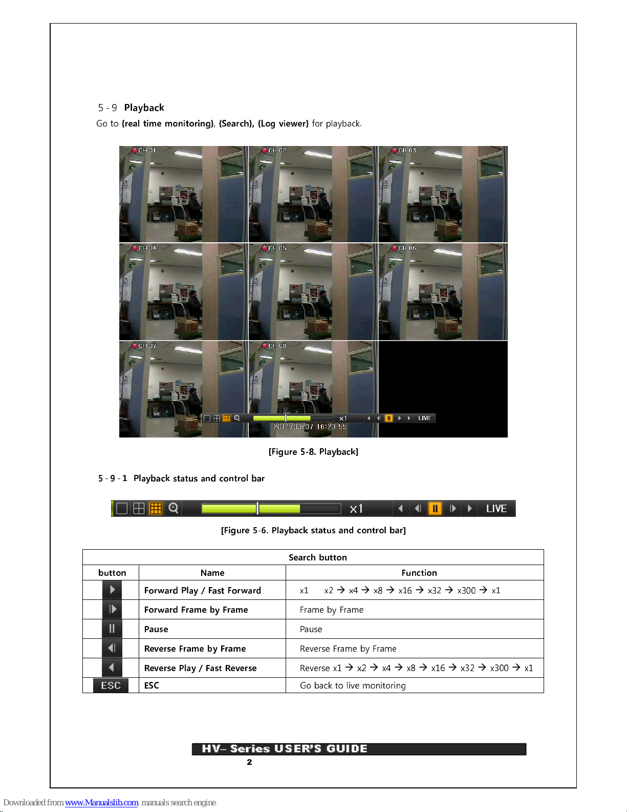
5-9
Playback
Go to
{real time monitoring}, {Search}, {Log viewer}
for playback.
[Figure 5-8. Playback]
5-9-1 Playback status and control bar
[Figure 5-6. Playback status and control bar]
Search button
button Name Function
Forward Play / Fast Forward
x1
x2
x4
x8
x16
x32
x300
x1
Forward Frame by Frame
Frame by Frame
Pause
Pause
Reverse Frame by Frame
Reverse Frame by Frame
Reverse Play / Fast Reverse
Reverse x1
x2
x4
x8
x16
x32
x300
x1
ESC
Go back to live monitoring

23
Operating Instruction & User’s Guide
5-10
Backup
Prior to backup, external devices which support USB2.0 interface should be connected. It may refer to
Appendix at the last page of user’s manual.
Backup may be executed live monitoring, search and backup.
[Figure 5-9. Backup]
① In live monitoring mode, go to {
Menu}
{Backup}.
② Select a device and check free and total space.
③ Setup for Time and Channel.
④ Backup will be preceded when start button is pressed.
If the backup storage device is not formatted, in case the box displaying the size of
the file to be backed up is displayed in yellow, and if backup is executed by pressing
the Copy (Backup) button, a prompt asking whether to erase the device will appear
as shown below. Selecting [YES] causes the storage medium for the selected device
to be erased.
5-11
Snapshot
Snapshot function lets the user create a JPG file in real-time monitoring, playback, search or log and backup
the image data.

24
Operating Instruction & User’s Guide
① To back up the currently displayed image, select
{Menu}
{Backup}
{Snapshot}
in real-time
monitoring mode, or
{Playback Menu}
{Backup}
{Snapshot}
in Playback mode.
② When a USB2.0 backup device (excluding ODD devices) is searched, the JPG file is stored in the same
device.
③ If there are no or more than two USB2.0 storage devices (excluding ODD devices), a window for
selecting the device will be displayed.
④ If the selected device is an ODD device, a prompt asking whether to back up the ODD device will be
displayed.

25
Operating Instruction & User’s Guide
6. Setup
6-1
Time
Go to
{Menu}
{Setup}
{Time}
.
[Figure 6-10. Date and Time]
(1) Date and Time
Date and Time can be changed in this menu.
(2) Date display type
It is selective among [dd/mm/yy] / [mm/dd/yy] / [yy/mm/dd].

26
Operating Instruction & User’s Guide
6-2
Definition
Go to
{Menu}
{Setup}
{Definition}
.
[Figure 6-11. Definition]
6-2-1Camera
(1) Name
Name for each camera channel can be setup with Max. 20letters.
(2) Covert
Camera image is hidden in covert.
※ In live monitoring mode, screen will be shown in black
It is actually recorded in covert.
(3) Adjust
Brightness/Contrast/Color/Hue/Sharpness/Camera adjustment can be setup.
6-2-2 Event Source
Motion area and sensitivity can be setup.

27
Operating Instruction & User’s Guide
6-3
Action
Go to
{Menu}
{Setup}
{Action}
.
[Figure 6-12. Action]
6-3-1 Recording
Recording resolution, frame rate, Audio Recording Setup
Recording resolution
Mode
resolution
NTSC PAL
CIF
352ⅹ240 352ⅹ288
2CIF
704ⅹ240 704ⅹ288
4CIF
704ⅹ480 704ⅹ576
Recording frame rate
Normal Speed
For Continuous Recording fps setup.
Event Speed
For Event(Motion) Recording fps setup
※ In case of
Normal Speed “
0”, recording will be made as follows.
6-3-2 Alarm
Alarm is to notify occurrences such as events and system incidents [Video Signal disconnected/HDD full/HDD
fail/HDD warning] to [Alarm/E-mail/System check].
.

28
Operating Instruction & User’s Guide
6-4
Storage
Go to
{Menu}
{Setup}
{Storage}.
[Figure 6-13. Storage]
6-4-1 Private Recording
This is a menu to setup Max. Recording days.
6-4-2 Local Storage Management
(1) Local Storage Management Function
NEW
Returns the status of the selected storage device to New; if this command is
executed, the selected storage device will be moved to the {New} storage device
manager.
Recording Initialize –
Initialize for Recording purpose
Backup Initialize –
Initialize for Backup purpose
Recording
This is a storage list for Recording.
※
Single device is required for Recording, at least.
New – Go back to NEW device
Online – Go to Online mode
.
Offline – Go to Offline mode
(Not suitable for Recording)
Format – Format
(in Offline status only)
Eject – Remove a device from DVR completely
Backup
Device for backup

29
Operating Instruction & User’s Guide
(2) Local Storage Management
※ There are three software status types.
Active
Connected to storage or backup device; currently saving the data.
Online
Only connected to storage or backup device.
Offline
Not connected to storage or backup device.
※ There are three hardware status types.
Healthy
Connected to storage or backup device; functions normally.
Warning
Connected to storage or backup device, but error was detected; in this case,
data storing or backup cannot be made (for more information, see the
description below).
Fault
Not connected to storage or backup device; cannot perform data saving or
backup.
1. Fault State
: The storage device is completely damaged, and none of the S/W
operations can be performed. The fault state is not related to a DVR problem. The DVR
has detected the fault and stopped the recording.
2. Warning State
: The storage device has a physical error that can be corrected by the
storage device or by the DVR. If the error is not taken care of, however, the storage
device is likely to be damaged (and shift to fault state). Backing up data in the
corresponding storage device and replacing the device with a normal one are strongly
recommended.
3. If there is an active storage device with a warning or a fault, a message is displayed on
the upper left part of the screen

30
Operating Instruction & User’s Guide
6-5
Network
Go to
{Menu}
{Setup}
{Network}
.
[Figure 6-14. Ethernet]
6-5-1 Ethernet
Setup for IP, ADSL, Gateway and DNS.
6-5-2 DDNS
As part of the DNS system, the Dynamic Domain Name System (DDNS) service updates the IP addresses of
host names in real time and allocates fixed domain names to systems linked to dynamic IP addresses to
allow users to use the same DNS name regardless of the changes in the IP address.
The MM/MH, SM/SH series provides dynamic DNS to ensure URL access in the dynamic IP environment.
User can monitor the remote place thru internet with web server functions which is equipped in DVR.
※ DynDNS On’ is for users who have ID of www.dyndns.com.
6-5-3Port
Network port setup can be done.
When UPnP is On, either Success or Fail message is shown.
6-5-4 E-Mail
Alarm Out setup in case when an alarm or an event occurs

31
Operating Instruction & User’s Guide
6-5-5 Bandwidth
This is to adjust Resolution/Quality/Frame of the image when user access to network for Live image.

32
Operating Instruction & User’s Guide
6-6
System
Go to
{Menu}
{Setup}
{System}
.
[Figure 6-15. System Setup]
DVR Name
DVR Name
User registration
Used to register, add, or delete users.
Administrator Password
Used to set the password of the Local System Administrator.
Upgrade
Upgrades the system firmware.
Factory setup
Initialize Setup(Except for network setup value).
Alarm Function
Alarm On/Off setup
Alarm Time Setup
Set the alarm On/Off and alarm format.
Monitor Type
Monitor Type Setup (Normal / Wide)
Image Ratio
Image ratio setup depending on monitor type
(HV-600 only)
Language
System language setting

33
Operating Instruction & User’s Guide
APPENDIX
A/P/P/E/N/D/I/X
(1) Recommended HDD
Type Size Capacity Buffer RPM
SATA I, II 3.5“ 1, 2 Flat Min. 80GB ~ Max. 1.5TB Over 8MB
Over 7200
(2) Recommended USB2.0 device
USB2.0 device Media File System
Memory Stick Flash Type FAT32
2.5’’ Portable USB HDD HDD Type FAT32

 Loading...