

Rievtech PR-6AC-R, PR-6DC-DA-R, PR-12AC-R-HMI, PR-12AC-R-E-CAP, PR-12DC-DA-R-HMI User Manual
...
Applied to ELC&PR series Ver: 3.0
Programmable Relay User's Manual
Rievtech Electronic Co.,Ltd

2
Contents
Introduction
Getting started
Installation and wiring
Programming xLogic
Configuring &software
Applications
Technical data

3
Introduction
Congratulations with your xLogic Micro PLC provided by Rievtech Electronic Co., Ltd.
The xLogic Micro PLC is a compact and expandable CPU replacing mini PLCs, multiple timers, relays and
counters.
The xLogic Micro PLC perfectly fits in the space between timing relays and low-end PLCs. Each CPU
incorporates not only a real-time clock and calendar, but also provides support for optional expansion I/O
modules to enhance control and monitoring applications. Data adjustments can easily be performed via
the keypad, the LCD display, or through the Rievtech-to-use xLogic soft. DIN-rail and panel-mounted
options are both available, offering full flexibility to the various installation needs of your application.
The xLogic Micro PLC is available in 120V/240V AC or 12V and 24V DC versions, making it the ideal
solution for relay replacement, or simple control applications as building and parking lot lighting,
managing automatic lighting, access control, watering systems, pump control, ventilation systems,
home automation and a wide field of other applications demanding low cost to be a primary design issue.
We strongly recommended taking the time to read this manual, before putting the xLogic Micro PLC to
work. Installation, programming and use of the unit are detailed in this manual. The feature-rich xLogic
Micro PLC provides a for off-line operation mode, allowing full configuration and testing prior to in-field
service commissioning. In reviewing this manual you will discover many additional advantageous product
properties, it will greatly simplify and optimize the use of your xLogic Micro PLC.
Valid range of this manual
The manual applies to devices of ELC series and PR series modules . For more information about EXM
series module(GSM and WIFI module) ,please refer to the x-Messenger user's manual.
Safety Guideline
This manual contains notices you have to observe in order to ensure your personal safety, as well as to

4
prevent damage to property. The notices referring to your personal safety are highlighted in the manual
by a safety alert symbol; notices referring to property damage only have no safety alert symbol. The
notices shown below are graded according to the degree of danger.
Caution
Indicates that death or severe personal injury may result if proper precautions are
not taken
Caution
With a safety alert symbol indicates that minor personal injury can result if proper
precautions are not taken.
Caution
Without a safety alert symbol indicates that property damage can result if proper
precautions are not taken.
Attention
Indicate that an unintended result or situation can occur if the corresponding
notice is not taken into account.
If more than one degree of danger is present, the warning notice representing the highest degree of
danger will be used. A notice warning of injury to persons with a safety alert symbol may also include a
warning relating to property damage.
Qualified Personnel
The device/system may only be set up and used in conjunction with this documentation. Commissioning
and operation of a device/system may only be performed by qualified personnel. Within the context of
the safety notices in this documentation qualified persons are defined as persons who are authorized to
commission, ground and label devices, systems and circuits in accordance with established safety
practices and standards. Please read the complete operating instructions before installation and
commissioning.
Rievtech does not accept any liability for possible damage to persons, buildings or machines, which occur
due to incorrect use or from not following the details.

5
Prescribed Usage
Note the following:
Warning
This device and its components may only be used for the applications described in the catalog or the
technical description, and only in connection with devices or components from other manufacturers
which have been approved or recommended by Rievtech. Correct, reliable operation of the product
requires proper transport, storage, positioning and assembly as well as careful operation and
maintenance.
Trademarks
All names identified by xLogic are registered trademarks of the Rievtech. The remaining trademarks in
this publication may be trademarks whose use by third parties for their own purposes could violate the
rights of the owner.
Copyright Rievtech 2015 all rights reserved
The distribution and duplication of this document or the utilization and transmission of its contents are
not permitted without express written permission. Offenders will be liable for damages. All rights,
including rights created by patent grant or registration of a utility model or design, are reserved.
Disclaim of Liability
We have reviewed the contents of this publication to ensure consistency with the hardware and software
described. Since variance cannot be precluded entirely, we cannot guarantee full consistency. However,
the information in this publication is reviewed regularly and any necessary corrections are included in
subsequent editions.
Additional support
We take pride in answering your question as soon as we can:
Please consult our website at www.rievtech.com for your closest point of contact or email us at
sales@rievtech.com

6
Contents
Contents
Chapter 1 General Introduction to xLogic
1.1 Overview
1.2 Highlight feature
Chapter 2 Hardware models and resources
2.1 Naming Rules of ELC&PR Series
2.2 Hardware model selection
2.3 Structure & dimension
Chapter 3 Installing/removing xLogic
3.1 DIN rail mounting
3.2 Wall-mounting
3.3 wiring xLogic
Chapter 4 Parameters modification HMI operation
4.1 Overview of xLogic menu
4.2 LCD panel instruction
4.3 Select function page
Chapter 5 Configuring & Programming software
5.1 xLogic Functions
5.2 General Input & Output functions
5.3 Basic functions list – GF
...........................................................................................................................................................................................
........................................................................................................................
...............................................................................................................................................................................
................................................................................................................................................................
....................................................................................................................
..................................................................................................................................
..............................................................................................................................................
.....................................................................................................................................................
...............................................................................................................................
..............................................................................................................................................................
.....................................................................................................................................................................
........................................................................................................................................................................
3.4.1 Connecting the power supply
3.4.2 Connecting xLogic inputs
3.4.3 Connecting xLogic Outputs
3.4.4 Communication port instructions:
...............................................................................................................................................
.......................................................................................................................................................
.........................................................................................................................................................
4.3.1 How to switch Run/Stop
4.3.2 Set parameter
4.3.3 Set password
4.3.4 How to set address of CPU and expansion module
4.3.5 Set LCD (backlight and Contrast)
4.3.6 Set communication parameters
4.3.7 Modification of System Time
5.2.1 Inputs
5.2.2 Cursor keys
5.2.3 Outputs
5.2.4 Permanent logical levels HI and LO
5.2.5 Panel Key
5.2.6 Shift register bits
5.2.7 Analog inputs
5.2.8 F (digital flag)
5.2.9 AF (Analog flag)
5.3.1 AND
5.3.2 AND with edge evaluation
.........................................................................................................................................................................
.............................................................................................................................................................................
.........................................................................................................................................................
...........................................................................................................................................................
.................................................................................................................................................................
..............................................................................................................................................................
......................................................................................................................................................................
..................................................................................................................................................................
...................................................................................................................................................
...........................................................................................................................................................
..........................................................................................................................................................
......................................................................................................................................................
..................................................................................................................................................
............................................................................................................................
....................................................................................................................................
................................................................................................................................
...................................................................................................................
......................................................................................................................................
....................................................................................................................
.......................................................................................................................
.............................................................................................................................
..........................................................................................................
...............................................................................................................................
................................................................................................................
..................................................................................................................................
..................................................................................................
..................................................................................
6
11
11
11
16
16
17
19
23
24
25
28
28
29
33
35
38
38
39
42
44
44
47
51
54
56
58
60
61
61
61
62
62
63
63
64
64
65
66
66
67
68

7
5.3.3 NAND
5.3.4 NAND with edge evaluation
5.3.5 OR
5.3.6 NOR
5.3.7 XOR
5.3.8 NOT
5.3.9 Boolean Function
5.4 Basics on special functions
5.4.1 Designation of the inputs
5.4.2 Time response
5.4.3 Backup of the real-time clock
6.4.4 Retentivity
5.4.5 Parameter protection
5.4.6 Calculating the gain and offset of analog values
5.5 Special functions list – SF
5.5.1 On-delay
5.5.2 Off-delay
5.5.3 On-/Off-delay
5.5.4 Retentive on-delay
5.5.5 Wiping relay (pulse output)
5.5.6 Edge triggered wiping relay
5.5.7 Asynchronous pulse generator
5.5.8 Random generator
5.5.9 Stairway lighting switch
5.5.10 Multiple function switch
5.5.11 Weekly timer
5.5.12 Yearly timer
5.5.13 Up/Down counter
5.5.14 Hours counter
5.5.15 Threshold trigger
5.5.16 Latching relay
5.5.17 Pulse relay
5.5.18 Message text
5.5.18.1 How to change parameters of blocks in displayed message ?
5.5.19 Softkey
5.5.20 Shift register
5.5.21 Analog comparator
5.5.22 Analog threshold trigger
5.5.23 Analog amplifier
5.5.24 Analog value monitoring
5.5.25 Analog differential trigger
5.5.26 Analog multiplexer
5.5.27 System cover
5.5.28 Pulse Width Modulator (PWM)
..........................................................................................................................................................................
...............................................................................................................................
................................................................................................................................................................................
.............................................................................................................................................................................
.............................................................................................................................................................................
..............................................................................................................................................................................
....................................................................................................................................................
.............................................................................................................................................
....................................................................................................................................
.........................................................................................................................................................
...........................................................................................................................
.................................................................................................................................................................
............................................................................................................................................
...............................................................................................................................................
....................................................................................................................................................................
....................................................................................................................................................................
..........................................................................................................................................................
................................................................................................................................................
...............................................................................................................................
...............................................................................................................................
.........................................................................................................................
.................................................................................................................................................
......................................................................................................................................
....................................................................................................................................
.........................................................................................................................................................
.........................................................................................................................................................
..............................................................................................................................................
.....................................................................................................................................................
..............................................................................................................................................
.....................................................................................................................................................
...........................................................................................................................................................
.......................................................................................................................................................
..................................................................................................................................................................
.......................................................................................................................................................
...........................................................................................................................................
................................................................................................................................
................................................................................................................................................
................................................................................................................................
..............................................................................................................................
...........................................................................................................................................
......................................................................................................................................................
.....................................................................................................................
......................................................................................
............................................
69
70
71
72
72
73
74
75
75
76
76
77
77
77
79
83
85
86
87
89
90
91
92
94
96
97
102
107
109
111
113
114
115
124
125
127
129
132
134
135
137
139
141
142

8
5.5.29 Analog Ramp
5.5.30 Analog Math
5.5.31 Analog math error detection
5.5.32 Modbus Read
5.5.33 Modbus Write
5.5.34 Modbus read write
5.5.35 Data latching relay
5.5.36 PI controller
5.5.37 Memory write
5.5.38 Memory Read
5.5.39 Word to Bit
5.5.40 Bit to Word
5.5.41 Stopwatch
5.5.42 Analog filter
5.5.43 Max/Min
5.5.44 Average value
5.5.45 Device Reset
5.5.46 Comport Status
5.5.47 Astronomical clock
5.5.48 Cam Control
5.5.49 Angular Cam Timer
5.5.50 Pumps Management
5.5.51 Defrost
5.5.52 Comparison of 2 values
5.5.53 Multicompare
5.5.54 Compare in zone
5.5.55 Conversion Word bits
5.5.56 Conversion bits Word
5.5.57 Demultiplexer
5.5.58 Multiplexing
5.5.59 Multiplexer
5.5.60 Square Boot
5.5.61 Sin Cos
5.5.62 Absolute Humidity
5.6 xLogicsoft
5.7 Main Functions
5.8 Operation Instructions
5.8.1 Menu Bar
...........................................................................................................................................................................
5.8.1.1 File
5.8.1.2 Edit
5.8.1.3 Tools
5.8.1.4 SMS
5.8.1.5 View
5.8.1.6 Help
......................................................................................................................................................
........................................................................................................................................................
......................................................................................................................................................
......................................................................................................................................................
.........................................................................................................................................................
.....................................................................................................................................................
......................................................................................................................................................
..........................................................................................................................................................
..........................................................................................................................................................
............................................................................................................................................................
.........................................................................................................................................................
................................................................................................................................................................
.....................................................................................................................................................
.......................................................................................................................................................
.................................................................................................................................................
........................................................................................................................................................
..................................................................................................................................................................
......................................................................................................................................................
...............................................................................................................................................
.....................................................................................................................................................
.........................................................................................................................................................
...........................................................................................................................................................
........................................................................................................................................................
..................................................................................................................................................................
..................................................................................................................................................................
...................................................................................................................................................
.................................................................................................................................................................
.................................................................................................................................................................
................................................................................................................................................................
..............................................................................................................................................................
...............................................................................................................................................................
........................................................................................................................
............................................................................................................................................
...........................................................................................................................................
............................................................................................................................................
..........................................................................................................................................
........................................................................................................................................
..................................................................................................................................
......................................................................................................................................
......................................................................................................................................
............................................................................................................................................
145
147
149
151
157
161
167
169
180
184
187
189
190
192
193
196
197
199
202
204
205
206
208
209
210
211
212
213
213
214
215
216
216
217
218
224
224
225
225
226
226
227
228
228

9
5.8.2 Toolbar
5.8.3 Programming Toolbar
5.8.4 Simulation Tool and status window
5.9 Basic Operation
5.9.1 Open File
5.9.1.1 Open New File
5.9.1.2 Open Existed Document
5.9.2 Edit Function Diagram Program
5.9.2.1 Place Function Block
5.9.2.2 Edit Property of Function Block
5.9.2.3 Setup link
5.9.2.4 Delete Function Block or Delete Link
5.9.2.5 Change block index
5.10 Simulation Running
5.11 Save and Print
5.12 Modify Password and transfer the Program
5.13 On-line monitoring/test circuit program
Chapter 6 How to configure the Ethernet CPU ?
6.1 How to separate the new version and old version?
6.2 How to Configure the Network parameters through program software?
6.3 How to view and configure the Ethernet parameters through LCD panel?
6.4 How to create the communication between the CPU and PC through Ethernet?
6.4.1 CPU works as TCP server
6.4.2 CPU works as TCP Client
6.4.2 CPU works as UDP Server
6.5 How to log on the built-in Web server
6.5.1 How to enable the webserver?
6.5.2 How to log on the webserver?
6.6 How to establish the communication between new Ethernet CPUs?
6.6.1 Example1: One master CPU(TCP server) connect with 3 slave CPUs(TCP Clients)
6.6.2 Example2: One master CPU(TCP Client) connect with 3 slave CPUs(TCP Servers)
6.6.3 Example3: One master CPU(UDP Server) connect with 3 slave CPUs(UDP clients)
6.6.4 Example4: One master CPU(UDP Client) connect with 3 slave CPUs(UDP Servers)
6.7 Configuration with DeviceManager
6.8 Establish communication between CPU and xLogicSoft/SCADA via Ethernet.
6.9 How to establish the communication among CPUs via Ethernet ?
Chapter 7 Applications
7.1 Dual-function switch
7.1.1 Standard solution
7.1.2 The scheme of xLogic
7.2 Automatic gate
7.2.1 Standard solution
7.2.2 The scheme of xLogic
7.3 Ventilation system
.....................................................................................................................................................................
.........................................................................................................................................
..............................................................................................................
................................................................................................................................................................
.................................................................................................................................................................
...........................................................................................................................................
.......................................................................................................................
....................................................................................................................
...............................................................................................................................
..........................................................................................................
...................................................................................................................................................
...............................................................................................
................................................................................................................................
......................................................................................................................................................
................................................................................................................................................................
.......................................................................................................
..............................................................................................................
........................................................................................................
...................................................................................
.........................................................................................................................
..........................................................................................................................
........................................................................................................................
............................................................................................................
...............................................................................................................
...............................................................................................................
..................................................
...................................................................................................................
......................................................
..........................................................................................................................................................
......................................................................................................................................................
...............................................................................................................................................
........................................................................................................................................
.................................................................................................................................................................
................................................................................................................................................
........................................................................................................................................
...........................................................................................................................................................
..........................................
......................................
..........................
.......
.......
......
.....
.............................
228
229
230
233
233
233
235
236
236
236
237
239
240
240
242
243
245
251
251
252
257
261
261
265
270
271
272
273
281
282
289
297
303
311
321
323
335
335
335
337
338
339
340
342

10
7.3.1 Standard solution
7.3.2 The scheme of xLogic
7.4 Factory door
7.4.1 Standard solution
7.4.2 The scheme of xLogic
7.5 Daylight lamp system
7.5.1 Standard solution
7.5.2 The scheme of xLogic
7.6 Rainwater pump
7.6.1 Standard solution
7.6.2 The scheme of xLogic
Chapter 8 Modbus function code and Register addresses
8.1 xLogic modbus function code
8.2 Register addresses of xLogic
Appendix
A Technical data
A.3 Switching capacity and service life of the relay outputs
......................................................................................................................................................................
.....................................................................................................................................................................................
.......................................................................................................................................................................
................................................................................................................................................
........................................................................................................................................
................................................................................................................................................
........................................................................................................................................
....................................................................................................................................................
................................................................................................................................................
........................................................................................................................................
...............................................................................................................................................................
................................................................................................................................................
........................................................................................................................................
......................................................................................
....................................................................................................................................
......................................................................................................................................
.................................................................................
342
343
345
345
346
348
349
349
351
352
353
354
354
355
364
364
390

11
Chapter 1 General Introduction to xLogic
4-lines, 16-characters per line, backlight display.
Multiple value display and input via keypad and LCD display.
70 kinds of function Blocks can be used in a circuit program in maximum
1.1 Overview
xLogic is a universal logic module made by Rievtech.
xLogic , a compact, expandable CPU that can replace mini PLC, multiple timers, relays and counters,
Splitting the difference between a timing relay and a low-end PLC, Each CPU has a real-time clock and
calendar, and supports optional expansion I/O modules to enhance your control and monitoring
applications . Data adjustments can be done via the on-board keypad and LCD display, or with xLogicsoft.
It can be either DIN-rail or panel mounted, depending upon the needs of your application, and it is
available in 120V/240V ac as well as 12V and 24V dc versions, and it is the ideal solution for relay
replacement applications, simple control applications such as building and parking lot lighting, managing
automatic lighting, access control, watering systems, pump control, or ventilation systems in factory, and
home automation and applications in which cost is a primary design issue.
1.2 Highlight feature

12
Standard Modbus RTU/ASCII/TCP communication protocol supported.
It’s optional for xLogic to act as slave or master in certain Modbus communication network.
(easy connect to other factory touch screen by RS232 cable, RS485 module)
CAN BUS protocol based expansion modules(PR-18/PR-24 series CPU)
Expandable up to 16 linked IO expansion modules reaching 282 I/O points in maximum
Optional RS232, RS485 and Ethernet connectivity
Multiple channels analog inputs available with DC 0-10V signal ,PT100 signal& 0/4….20mA.
Default Real Time Clock (RTC) and summer/winter timer is available
Backup at Real Time Clock (RTC) at 25 °C:20 days
4 channels high-speed counting
Pre-configured standard functions, e.g. on/ off-delays, pulse relay and softkey
2 PWM channels(10KHz in maximum)
Retentive memory capability (Not applied to PR-6&PR-12-E series CPU)
RS232 and USB communication download cable with photo-electricity isolation
Programmable capability up to 1024 function blocks(PR-18/PR-24);512 function
Mounting via modular 35mm DIN rail or screw fixed mounting plate
On-line monitor capability(Free charge SCADA for all series xlogic)
Datalogging
Kinds of analog signals process capacity (DC 0..10V ,0/4...20mA and PT100 probe inputs and DC
Low cost
blocks(PR-12&ELC-12-N) and 64 function blocks for PR-6&PR-12-E
0..10V and 0/4...20mA outputs)
Some of the things xLogic can do for you?
The xLogic Micro PLC provides solutions for commercial, industrial, building and
domestic applications such as lighting, pumping, ventilation, shutter operations or
in switching cabinets. The application field is widespread and these are just a few to mention.
Using the RS485 bus and Ethernet connectivity allows the user to realize various extensive (real-time)
monitoring and control applications.
Special versions without operator panel and display unit are available for series production applications
in small machine, installation and cabinet building environments to further slash cost.
xLogic devices:
xLogic Basic is available in two voltage classes:
*Classes 1:DC12-24V: i.e.: PR-6DC Series, PR-12DC series, PR-18 series, PR-24DC series.

13
*Classes2: AC110-240V: i.e.: PR-6AC Series, PR-12AC series, PR-18AC series , PR-24AC series.
xLogic:RS232 communication cable (Model:ELC-RS232)
xLogic: USB communication cable (Model: ELC-USB).
xLogic: PRO-RS485 cable (Model: PRO-RS485).
xLogic: RS485 module(Model:PR-RS485)
In the versions:
* With Display: with “-HMI” model, such as PR-12DC-DA-R-HMI
* Without Display: PR-6 series and with “-CAP” model, such as PR-12DC-DA-R-CAP. Only PR-12 has -CAP
version. PR-18,PR-24 all have display in default.
.
Expansion modules:
PR-E (applied to PR-18/PR-24 CPU)
* xLogic digital modules are available for operation with 12…24V DC, and 110.. .240 V AC, and are
equipped with eight inputs and eight outputs.
* xLogic analog modules are available for operation with 12…24 V DC and are equipped with six digital
and 4 analog inputs.
Communication cable and module:
It is kind of universal cable with photoelectricity isolation which can be directly connected to standard
9-pin port of PC, also kind of interface module which can enable user’s program to be downloaded into
xLogic CPU through xLogicsoft for running. It also is the connection cable between CPU and third party
device with the RS232 port(just like HMI) in modbus communication system.
It is kind of communication cable with photoelectricity isolation through which PC with USB port only can
be connected to xLogic main module, moreover, it has same features as ELC-RS232 module, so it is
quite convenient for user whose computer has no standard serial port.
It is kind of converter cable with photoelectricity isolation to make the program port serves as RS485
port.
isolated 485 converter,used to bring out the terminals of RS485 port built-in PR-18,PR-24 series CPU for
connection with third party devices.
Communication / Network

14
xLogic offers different ways to communicate within the system.
RS485 port
The RS485 port is used for communication between the CPU and various devices or equipments which
have the standard RS485 port. Communicate using Modbus RTU/ASCII protocol.
Note:PR-RS485 module is required to connect the CPU to RS485 BUS.
RS232 or USB port (ELC-ES232/ ELC-USB needed)
If there is no network required and only one main module with some expansion modules is needed for the
application, the down- and upload of the project to and from the main module happens over the standard
RS232 or USB port. It allows system maintenance like monitoring too.
Note:PR-E-RS485 module is required to connect the CPU to RS485 BUS.
Ethernet network
If the application requires a system where more than one main module is needed and these main
modules have to communicate, each Ethernet CPU will be connected directly to the Ethernet by the
built-in LAN port. The project down- and upload to and from the main modules and the communication
between the CPU happens over the Ethernet network. Furthermore the our free of charge SCADA can be
also established connection with Ethernet CPU

15
Note
Digital inputs I1 to I4(PR-6), I1 to I8(PR-12), I1 to IC(ELC-18),I1 to IE(PR-24). I11-I18(Expansion
Analog inputs I1 to I6(PR-18/PR-24), I1 to I4(PR-12), I11 to I14(PR-E expansion with address
Digital outputs Q1 to Q6(PR-18), Q1 to Q4(PR-12),Q1 to QA(PR-24);Q11 to Q18((PR-E expansion
Digital flag blocks F1-F32(PR-6,PR-12-E), F1-F256(PR-12/PR-18/PR-24) ;
-F8 : Startup flag
-F64: Backlight control bit(to control the backlight of LCD and backlight of ELC-43TS)
-F63: Buzzer of ELC-43TS control bit
Analog flag blocks AF1 to AF256(PR-12/PR-18/PR-24);AF1-AF32(PR-6/PR-12-E)
Shift register bits S1 to S8
xLogic CPU may be equipped with expansion modules of the different voltage class, but expansion
module must be supplied the correct power corresponding to its type.
Each xLogic CPU provides the following connections for the creation of the circuit program, regardless of
the number of connected blocks:
with address 1)...I161--I168(Expansion with address 16)
1),....AI161 to AI164(PR-E expansion with address 16)
with address 1), Q161 to Q168(PR-E expansion with address 16)

16
Chapter 2 Hardware models and resources
2.1 Naming Rules of ELC&PR Series
1.Series name: ELC series; PR series.
2.Points of input and output
3.Supply power AC or DC
4.Digital/Analog D: digital DA: digital/analog
5.Output type R: relay T: transistor TN = “PNP” transistor; TP= “NPN” transistor
6. E: economic mode
7. N: Ethernet port built-in
Note:
The model end with “-HMI” means the CPU has LCD and panel keys on it;
The model end with “-CAP” means the CPU has no LCD on it.
Model name (expansion module ,plus with PR-18/PR-24 CPU together to use):
1.Series name
2.E: expansion module
3.Points of input and output
4.Supply power AC or DC

17
5.Digital/Analog D: digital DA: digital/analog
PR-6 Series CPU Units (None expandable)
Model
Expansion
Supply voltage
Inputs
Outputs
High-speed
count
PWM
HMI
RTC
PR-6AC-R
no
AC110~AC240V/
DC110-DC240V
4 digital
2 relays (10A)
nonono
yes
PR-6DC-DA-R
no
DC12-24V
4 digital/4(0...10V)
2 relays (10A)
nonono
yes
PR-12 Series CPU Units(None expandable)
Model
Expansio
n
Supply voltage
Inputs
Outputs
High-speed c ount
PWM
HMI
RTC
PR-12AC-R-HMI
no
AC110~AC240V
8 digital
4 relays (10A)
nonoyes
yes
PR-12AC-R-E-CAP
no
AC110~AC240V
8 digital
4 relays (10A)
nonono
yes
PR-12DC-DA-R-HMI
no
DC12-24V
4(0...10V)+4 digital
4 relays (10A)
4(I5-I8)(60KHZ)
no
yes
yes
PR-12DC-DA-R-E-CAP
no
DC12-24V
4(0...10V)+4 digital
4 relays (10A)
nonono
yes
PR-12DC-DA-TN-HMI
no
DC12-24V
4(0...10V)+4 digital
4Transistor(0.3A/
PNP)
4 (I5-I8)(60KHZ)
Yes(10KHZ)
yes
yes
PR-14 Series CPU Units(Expandable)-built-in RS485 port
Model
Expansion
Supply voltage
Inputs
Outputs
High-speed c ount
PWM
HMI
RTC
PR-14AC-R-HMI
yes
AC110~AC240V
/DC110-DC240V
10 digital
4 relays (10A)
nonoyes
yes
PR-14DC-DA-R-HMI
yes
DC12-24V
6(0...10V)/6digit
al+4 digital
4 relays (10A)
4(I7-IA)(60KHZ)
no
yes
yes
PR-18 Series CPU Units(Expandable)
Model
Expansion
Supply voltage
Inputs
Outputs
High-speed c ount
PWM
HMI
RTC
PR-18AC-R-HMI
yes
AC110~AC240V
/DC110-DC240V
12 digital
6 relays (10A)
nonoyes
yes
PR-18DC-DA-R-HMI
yes
DC12-24V
6(0...10V)/6digit
al+6 digital
6 relays (10A)
4(I9-IC)(60KHZ)
no
yes
yes
PR-18DC-DA-RT-HMI
yes
DC12-24V
6(0...10V)/6digit
al+6 digital
4 relays (10A)+
2 transistor(0.3A)
4(I9-IC)(60KHZ)
yes(10khz)
yes
yes
PR-24 Series CPU Units(Expandable)-built-in RS485 port
Model
Expansion
Supply voltage
Inputs
Outputs
High-speed
count
PWM
HMI
RTC
6.Output type R: relay TP: “NPN” transistor;TN :“PNP” transistor
2.2 Hardware model selection

18
PR-24AC-R-HMI
yes
AC110~AC240V
16 digital
10 relays (10A)
nonoyes
yes
PR-24DC-DA-R-HMI
yes
DC12-24V
6(0...10V)/6digital
+8 digital
10 relays (10A)
4(I9-IC)(60KHZ)
no
yes
yes
PR-24DC-DAI-RTA
yes
DC12-24V
2(0/4...20mA)+
4(0...10V)/4digital
+8 digital
6
relays(10A)+2Transistor(0.3
A/PNP)+1(0...10V)/(0...20m
A)
4(I9-IC)(60KHZ)
YES(10khz)
yes
yes
Expansion Modules(For PR-18,PR-24 series)
Model
Supply voltage
Inputs
Outputs
PR-E-16AC-R
AC110~
AC240V
8 digital
4 relays(10A)+4 relays(3A)
PR-E-16DC-DA-R
DC12-24V
4digital+4analog(0..10V)/digital
4 relays(10A)+4 relays(3A)
PR-E-16DC-DA-TN
DC12-24V
4digital+4analog(0..10V)/digital
8 transistors(PNP)(0.3A)
PR-E-PT100
DC12-24V
3 Channels PT100, resolution: 0.5°), temperature range : -50℃- 200℃
none
PR-E-AQ-VI
DC12-24V
none
2 Channels (DC 0…10V/0...20mA)
PR-E-AI-I
DC12-24V
4 Channels (0/4…..20 mA), Current Signal
none
PR-RS485
DC12-24V
isolated 485 converter,used to bring out the terminals of RS485 port built-in PR-18&PR-24 series CPU for connection with third
party devices.
Accessories
ELC-RS232
RS232 communication module /download cable between PC and xLogic CPU u nits
ELC-USB
USB communication module /download cable between PC and xLogic CPU units
ELC-COPIER
ELC-COPIER can be used to save user program and download program into xLogics.(including all the ELC series and EXM series PLC)
ELC-MEMORY
Real time data-logging device with a mini-SD card slot for ELC&EXM series CPUs. The history data( IO status , analog value, current value of registers)
of ELC&EXM CPU can be recorded, retrieved an d viewed via it.
PRO-RS485
Converter cable from program port to RS485 port.
ELC-BATTERY
RTC BATTERY, t he RTC c an be backup f or 20days in default, but with this battery, the RTC shall be backup for 1 year(only can be applied with PR-18
CPU).

19
2.3 Structure & dimension
1.Power supply 2. Input 3. Program port for applied to ELC-6 CPU 4.Output
1.Power supply&Input terminals 2. Program Port(can be used as RS232 port with ELC-RS232 or RS485
1. PR-6 Series CPU&EXM-E Series Extension
2. Standard PR-12 series with LCD model:
port with PRO-RS485) 3.HMI/LCD panel 4.keypad 5.Output terminals
3. Economic PR-12 series without LCD model:

20
1.Power supply&Input terminals 2. Program Port(can be used as RS232 port with ELC-RS232 or RS485
1.Power supply&Input terminals 2.HMI/LCD panel 3.keypad 4.Output terminals 5. Program
port with PRO-RS485) 3.RUN/STOP Indicator 4.Output terminals
4. PR-14 and PR-18 series model:
Port(can be used as RS232 port with ELC-RS232 or RS485 port with PRO-RS485) 6.Extension port
Dimensions of PR-14 and PR-18:

21
5. PR-24 series CPU
1. Power supply 2.Input 3. Program/RS232 port 4.HMI/LCD panel 5.keypad 6.Extension/RS485
port 7.Output
6. ELC-22 Ethernet CPU

22
1.Power supply 2.Input 3. Program/RS232 port 4.HMI/LCD panel 5.keypad 6.Extension/RS485
11. PR-E extension module:
port 7.Output 8.LAN port
1. Power supply&Input terminals 2. Connection cable between CPU and extension(Detached)
3.Extension port(left) 4. RUN/STOP indicator 5. Extension port( Right) 6. Output terminals
Dimensions of PR-E:

23
Dimensions of ELC-12-N Ethernet CPU:
EXM-E expansion module and PR-6 series CPU have a width of 48mm
PR-14,PR-18&ELC-12-N Series CPU has a width of 95mm.
PR-E expansion modules have a width of 72mm.
PR-24 Series CPU has a width of 133mm.
PR-12 Series CPU has a width of 72mm
Chapter 3 Installing/removing xLogic
Dimen si ons
The xLogic installation dimensions are compliant with DIN 43880.
xLogic can be snap-mounted to 35 mm DIN rails to EN 50022 or on the wall.
xLogic width:

24
Note
The figure below shows you an example of the installation and removal of an PR-18 CPU and one
expansion module of PR-18 CPU.
W a r n i n g
Always switch off power before you “remove” and “insert” an expansion module.
3.1 DIN rail mounting
Mounting
How to mount a xLogic module and an expansion module onto a DIN rail:
1. Hook the xLogic Basic module onto the rail.
2. Push down the lower end to snap it on. The mounting interlock at the rear must engage.
3. Hook the xLogic expansion module onto the rail
4. Slide the module towards the left until it touches the xLogic CPU.
5. Push down the lower end to snap it on. The mounting interlock at the rear must engage.
6. Remove the plastic cover in the expansion port of CPU and expansion module.
7. Plus the connector on the flat cable to CPU
Repeat the expansion module steps to mount further expansion modules.

25
Note:If you need install the expansion and CPU on different rows, you need order the longer
flat connection which is used to connected with CPU, the longest distance can
be 200meters between the CPU and the end expansion module.
Removal
To remove xLogic:
....... if you have installed only one xLogic Basic:
1. Insert a screwdriver into the eyelet at the bottom of the slide interlock and move the
latch downward.
2. Swing the xLogic Basic off the DIN rail.
....... if you have connected at least one expansion module to xLogic Basic:
1. Remove the connector on the flat cable
2. Slide the expansion module off towards the right.
3. Insert a screwdriver into the eyelet at the bottom of the slide interlock and lever it
downward.
4. Swing the expansion module off the profile rail.
Repeat steps 1 to 4 for all other expansion modules.
3.2 Wall-mounting
For wall-mounting, first slide the mounting slides on the rear side of the devices towards the outside. You
can now wall-mount xLogic by means of two mounting slides and two ØM4 screws (tightening torque 0.8
to 1.2 Nm).

26
Drilling template for wall-mounting
Before you can wall-mount xLogic, you need to drill holes using the template shown below.
All dimensions in mm
Bore hole for Ø M4 screw, tightening torque 0.8 to 1.2 Nm
1. xLogic CPU
PR-6 series:
PR-12 Series CPU

27
PR-14 and PR-18 series:
1.PR-18 CPU;2. PR-E extension
PR-24 series

28
ELC-12-N series(applied to CPU and extensions):
1 x 2.5 mm
2
2 x 1.5 mm2for each second terminal chamber
Tightening torque: 0.4.. .0.5 N/m or 3. ..4 lbs/in
3.3 wiring xLogic
Wire the xLogic using a screwdriver with a 3-mm blade.
You do not need wire ferrules for the terminals. You can use conductors with
cross-sections of up to the following thicknesses:
Note
Always cover the terminals after you have completed the i ns t al l at i on . To pr o te ct
xL o gi c a d e q u at e ly fr o m impermissible contact to live parts, local standards must
be complied with.
3.4.1 Connecting the power supply
The PR-6AC, PR-12AC,PR-18AC, PR-24AC versions of xLogic are suitable for
operation with rated voltages of 110 V AC and 240 V AC. The PR-6DC,
PR-12DC,PR-18DC, PR-24DC versions can be operated with a 12 or 24 VDC power
supply.

29
Note
1. Requirements
A power failure may cause an additional edge triggering signal.
Data of the last uninterrupted cycle are stored in xLogic
To connect xLogic to the power supply:
3.4.2 Connecting xLogic inputs
the inputs you connect sensor elements such as: momentary switches, switches, light barriers,
daylight control switches etc.

30
2.
AC Type
DC Type
Signal status 0
<40VAC
<0.03mA
<5VDC
Signal status 1
>79 VAC
Typical 0.06
>10VDC
Typical 0.3mA
Analogue input
NO
AI1-AI4(0-10V DC)(PR-6,PR-12)
Note:
1. For PR-6DC-DA-R, PR-12DC-DA ,PR-14DC-DA,
PR-18DC-DA ,PR-24DC-DA Series and versions. That can receive analog
input. They can be set to analog input or digital input as either may be
used in the program. They will be recognized as analog inputs when the
input terminal is connected with an analog function block, and they will be
recognized as switching inputs when the input terminal is not connected
with an analog function block.
2. The analog inputs require DC 0V ~ +10V voltage signals. These are
divided equally in 0.01V increments. In programming, all the block
parameters related to the analog inputs are based on the minimum
increment of 0.01V.
3. They can be recognized as switching input when the input voltage is more
than 10.0V and cannot be recognized as an analog input.
4. For the switching input off, when the switch status changes from 0 to 1,
the time of Status 1 must be greater than 50ms, and when the switch status
changes from 1 to 0, the time of Status 0 also must be greater than 50ms.
Connecting xLogic is shown as in the following figures:
* DC type digital inputs

31
* AC type digital inputs
* Analog Inputs (DC 0…10V)
*Analog inputs current Inputs (0…20mA)

32
The above figure shows how to make a four-wire current measurement.
PR-E-PT100
It can be connected with one two-wire or three-wire resistance-type thermocouple.
When two-wire technology applied, the terminals “M1+ and IC1” (this rule also shall be applied to” M2+
and IC2”, “M3+ and IC3” ) would be short connected. Such connection can not compensate
error/tolerance caused by the resistance in measurement loop. The measurement error of 1 Ω impedance
of power cord is proportional to +2.5 °C
The three-wire technology can inhibit the influence of measurement results caused by cable length
(ohmic resistance).
2-wire (short circuit M+ and Ic) 3 wire

33
3.4.3 Connecting xLogic Outputs
1. Requirement for the relay output
Various loads such as lamp, fluorescent tube, motor, contact, etc., can be connected to the outputs of
xLogic. The maximum ON output current that can be supplied by xLogic is 10A for the resistance load and
3A for the inductive load. The connection is in accordance with the following figure:
2. Requirement for the electronic transistor output:
The load connected to xLogic must have the following characteristics:
* The maximum switch current cannot exceed 0.3A.
* When the switch is ON (Q=1), the maximum current is 0.3A.
Notes (PNP):
* The load connecting voltage must be ≤60VDC and it must be DC.
* The “+” terminal of the output wiring must be connected with the DC positive
voltage, and it must be connected with the “L+” terminal of the xLogic power ,a
load must be connected with the “-” terminal of the DC negative voltage.

34
PR-E-AQ-VI(DC0..10V analog output).
EXM-E-AQ-I /PR-E-AQ-VI
PR-RS485
Actually, PR-RS485 is just a converter with photo isolation bringing out 3 wiring terminals(short circuited
inner of such 3 terminals, so only one channel RS485 bus is available) from RS485 port (2x8pin) of
CPU(PR-18/ELC-22/PR-24) for your easy connection with other devices.

35
If “RT1”, RT2” terminal are short connected, one 120R resistor will be connected between A/+ and B/-
3.4.4 Communication port instructions:
PR-6 CPUs
PR-14,PR-18 ,ELC-22 and PR-24 CPUs

36
1. Programming port/RS232 port
2. Expansion port/RS485 ( pin definition)
PIN
function
2
RXD
3
TXD
5
GND
others
NULL
(ELC-RS232 ,ELC-USB,ELC-Copier,ELC-MEMORY,ELC-BATTERY,PRO-RS485) should be inserted in this
port)
When the programming port should be used as the standard RS232 port (D-shape 9 pin header) ,the
ELC-RS232 cable needed.Blow is show you the pin definition of the header:

37
3------RS485 A
5------RS485 B
4------GND
6------GND
7------CANL
9------CANH
15------+5V
16------+5V
Communication between CPU and expansion module will use 4.7,9,15 pin.
PR-RS485 module is required when PR-18/ELC-22/PR-24 CPU communicate with the third party devices
via RS485 bus
PR-12 CPUs
With HMI model Without HMI model
1. Programming port/RS232
port(ELC-RS232 ,ELC-USB,ELC-Copier,ELC-MEMORY,ELC-BATTERY,PRO-RS485 should be inserted in this
port) Named COM0.
When the programming port should be used as the standard RS232 port (D-shape 9 pin header) ,the
ELC-RS232 cable is required.

38
Chapter 4 Parameters modification HMI operation
4.1 Overview of xLogic menu
PR-12 ,PR-14,PR-18,ELC-22,ELC-26 series CPU has same menu on the LCD, so here we show the PR-18
for example.
Parameter assignment mode
Parameter assignment menu:

39
4.2 LCD panel instruction
1. Display area: 4x16 characters can be displayed
2. 4 X Function key: operate the program by pressing down these key (Only for ELC-22-N and PR-24
3. 6x Panel key: you can modify the parameters, programming, view alarming message.
1. Display the RUN/STOP status of the CPU
2. Display or modify the Clock.
3. Display the IO status of CPU& extensions
4. Display all kinds registers value(AI/AO, Parameters of blocks etc)
5. Display multiple alarming messages
6. Modify the parameters of blocks
7. Backlight can be controlled via programming(Light on Alarm)
8. System cover message can be customized
9. Up to 64 different alarming messages is allowed.
10. The CPU address can be modified
11. Set password protection
12. Change communication parameters for COM port
PR-12 Series CPU PR-18 Series CPU ELC-22 and ELC-26 series CPU
series CPU, invalid for PR-12 and PR-18 series CPU;F1--F4 are all available on ELC-43TS)
What this operate panel can do for you?
……..
Menu shows:

40

41
After being powered on, xLogic shall self-check program stored in the CPU.
If the program is accurate, then the CPU will be running, meanwhile the system cover will show as
follows:
In xLogicsoft, this interface is defaulted as its initialization screen.
If there are several parameter pages, users can press or key to go to the page you would like.
The last page is the cursor mode:

42
Cursor keys can be controlled in this page by press arrow keys and ESC key at the same time.
If xLogic has several alarm interfaces in the same period and it only displays the message with highest
priority in the function block, also you may go through all alarm messages by pressing or key.
Note:
The message text block would be treated as parameter page only when it has no input, otherwise, it may
be regarded as alarm page. When input has high pulse, LCD shall display alarm message.
4.3 Select function page
Press ESC key to change from running mode to function page.
After pressing ESC key, xLogic would be switched to function page and meanwhile open function menu as
figure below shows.

43
Brief introduction on 5 options of function page:
Run/stop
Set Param
Set…
1. ”Press ”UP” or “DOWN” key to move the cursor to “Set….”
2. Then press OK key ,xLogic will display as follows:
Clock
Menu Language
Network(This only for Ethernet CPU)
Select this menu to switch over xLogic status between RUN and Stop. Refer to
chapter4.3.1 for details.
To set function block parameter. Refer to chapter 4.3.2 for details.
Used to set /modify password ,set address of CPU&extension , LCD settings and
communication parameters settings refer to chapter 4.3.3 and 4.3.4 for details
please.
To set and modify date and time .Refer to chapter 4.3.5 for details.
To change the language of the Menu. Refer to chapter 4.3.6 for detail
Recovery ET: when you press ok when the cursor stay on this menu, the Ethernet modem
built-in Ethernet CPU will be reset to default settings.

44
4.3.1 How to switch Run/Stop
1. Under the FUNCTION PAGE, select
You should first select FUNCTION PAGE. (Read 4.3)
1. Move the cursor to “Run/stop”: Press “UP” or “DOWN” key.
2. Move the cursor to "Yes": Press OK key.
After pressing ESC key, you’ll find out your circuit program has changed to “stop” status as figure below
shows:
4.3.2 Set parameter
If you want to select a parameter, you need do as the following procedures:
“Set parameter”: Press or key

45
2. Confirm by pressing OK key.
1. Move the cursor to the parameter to be modified: press or key.
2. Modify value: press or key.
Then xLogic displays the first parameter, so you can modify as you like. If there is no parameter to
set/modify, you can press ESC key to return.
3. Select parameter you intend to modify.
4. Select certain specific value of that parameter which you want to edit, then press OK key.
How to modify parameter?
A. First select certain parameter which you need to edit by following the below procedures:
1. Under the FUNCTION PAGE, select
“Set parameter”: Press or key
2. Confirm by pressing OK key.
B. then you can perform the below actions to modify parameter:
46
3. Confirm the value after modification: press OK key.
Note:
When xLogic is running, not only time value but also time unit(S,M,H) can be
altered , but Besides alter time parameter at RUN time ,you can alter time
base(s=second, m=minute ,h=hour).
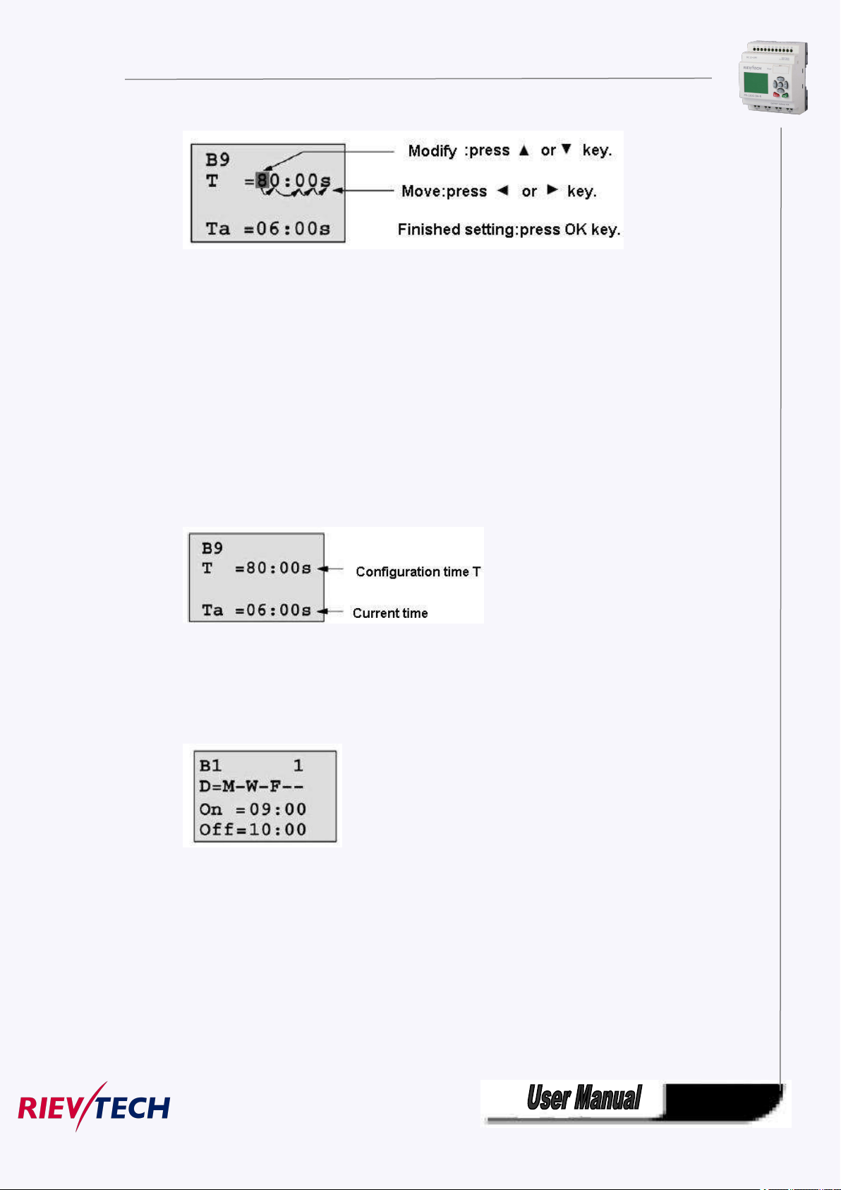
Current value of time T
View time T in parameter mode:
You are allowed to modify configuration time. Switch on/off time for a time segment.
In parameter mode, time segment figure of a timer:
You can alter the time and date of switch on/off.
Current value of counter
In parameter mode, the parameter view of a counter:

47
Current value of hour counter
In parameter mode, the view of hour counters:
You can edit configured time interval (MI).
Current value of threshold trigger
In parameter mode, the view of threshold trigger:
You can alter the threshold value of switching on /off.
4.3.3 Set password
xLogic supply password protection function for your program. You can choose according to your need.
See the following instruction; you’ll understand the method of setting password.
Set one password

48
A password contains less than or equal to 4 characters and each character is Arabian number from 0 to
9 .It is easy to specify, edit or remove the password directly on the xLogic in the “Password” menu of the
function page:
You should first select the FUNCTION PAGE. (Read 5.2)
1. Move the cursor to “Password”: Press “UP” or “DOWN” key.
2. Confirm “Password”: Press OK key.
Example: let us set “1234” as password for a program. Now the LCD displays the following interface:
Select “New” option, and then edit it.
3. Select “1”: press “UP” key once.
4. Move the cursor to the next character: press “Right” key.
5. Select “2”: press “UP” key twice.
6. Move the cursor to the next character: press “Right” key.
7. Select”3”: press “UP” key three times.
8. Move the cursor to the next character: press “Right” key.
9. Select “4”: press “UP” key four times.
Now display:
10. Confirm password: press OK key.
Now, the program is protected by the password of “1234”, and then you can return to the main menu.
Note:
You can cancel a password newly-set via ESC key. In this instance, xLogic will return to main menu and
not reserve that password. Such password is for the parameter, that means only when you operate the
menu of LCD, the password is required. The program password need be set in xlogicosoft by the menu
File->Property-> Parameter

49
Modify password:
In order to modify password, you are required to present current password.
In the menu of the FUNCTION PAGE:
1. Move the cursor to “Password”: Press “UP” or “DOWN” key.
2. Confirm “Password”: Press OK key.
Select “Old” and input primary password (in our instance is “1234”), the process is the same as the step
3 to step 10 mentioned above.
LCD displays:
Thus, you could select “New” to input new password such as “8888”:
3. Select “8”: press “UP” key.
4. Move the cursor to next character: press “Right” key.
Repeat the step 3 and 4 to realize the third and fourth character.
LCD displays:
4.Confirm new password: press OK key.
So you have set the new password and then return to main menu.

50
How to remove the password:
In case you need to remove password .e.g. allow the other users to edit your program, then you must
know the current password. The process of removing password is the same as that of modifying
password.
In the menu of the FUNCTION PAGE. :
1. Move the cursor to “Password”: Press “UP” or “DOWN” key.
2. Confirm “Password”: Press OK key.
Select “Old” and input primary password (in our instance is “8888”), the process is the same as the step
3 to step 10 mentioned above.
LCD displays as follows:
Input nothing under the “New”, and let it keep blank to clear password.
4.Confirm “blank” password: press OK key. Now you have cleared password and return to main menu. If
you want to set password next time, the LCD will display:
Password settings in xlogicsoft.

51
The menu File->Properties (Parameter)
1.The password which set in the LCD menu is the parameter password.
2.The program password cannot be set in the LCD menu, it only can be set in xlogicsoft.
A. Set CPU address
There are 2 password settings can be applied to the program, one is the program password,
one is parameter password.
Program password:
If you set the program password, then the password is required when you want to upload the
program into PC.
Parameter password:
If you set the parameter password, then the password is required when you want to upload the
program into PC.
Note:
4.3.4 How to set address of CPU and expansion module
If there are more than one CPU in a certain communication network,well then the address of CPU must
be set differently each other. You can change the address of CPU via xLogicsoft, or via the panel key if the
CPU with LCD panel. The address range is from 1 to 247 for ELC and PR series CPU

52
Confirm with "OK"
Change the address with arrow keys, and confirm with "Ok".
The CPU address also can be set by xlogicsoft, if the CPU without HMI, you only can set the expansion
address with such method.
You can set the CPU address by the menu Tools-> transfer-> set PLC’s address in xlogicsoft.
Part 2 :Set address of PR-E extensions.(PR-E-16DC-DA-R etc..)

53
1. Plastic slice
Step 1: Using a screwdriver , take the plastic slice down and we’ll find a dial switch.
2: Dial the switch as the below instructions to set the address what you need.
Up to 8 extensions (includes IO ,AQ,AI,PT100 modules) can be connected with the CPU .
The default address of PR-E extensions is 1 and the dial switch as below:
Address 1:
means the switch position
Address 2:
Address 3:
Address 4:
Address 5:
Address 6:
Address 7:

54
Address 8:
Notes:
1.The address setup of the extension module must be before powering on. Modification when powering
on will be ineffective.
2.Freely connection with CPU and expansion , do not care the power supply type of CPU and
extensions ,that means the AC type module also can be connected with the DC type module or AC type
expansion module also can be connected with DC type CPU.
3.If the communication is established between CPU and extensions , the indicator on the top of the
extensions’ house will turn to RUN(green color)(If the LED is red, that means the CPU cannot get
communication with it).
4.If more than one expansion module connect to CPU at the same time ,the address of expansion module
must be different each other, otherwise the system(CPU+expansions) would run abnormal, but if the
expansion already has each own separately address, then the installation sequence of the expansion is
not important anymore, for example you can let the expansion with address 8 as the first one with CPU.
4.3.5 Set LCD (backlight and Contrast)
The backlight of CPU can be set “ON” time as 10 sec or “ON” all the time. The setting way as follows:
1. Select “Set...” menu and click OK.
2. Select “Set LCD” menu and click “OK”

55
3.Select "Backlight"menu and click "OK"
4. Default is 10 seconds, and another option is "Always On". Confirm with "OK"
Modify the contrast
Confirm with "OK"

56
Modify the contrast with Left or right key, and confirm with "Ok".
4.3.6 Set communication parameters
Select "Set Com" menu from the menu "Set..".
Confirm with "Ok"
COM0: RS232 port or programming port.
COM1: RS485 port(For the PR-RS485 module which shall be connected to
PR-14,PR-18,PR-24,ELC-18,ELC-22,ELC-26 CPU)
COM2: Built-in RS485 port for PR-14 and PR-24CPU.
COM3: Ethernet port for ELC-22-N CPU, reserved for other series CPU.

57
Confirm with "OK"
Change it with pressing Up and Down key
And confirm with "OK"
Set Modbus protocol
Confirm with "OK"

58
Change with Up and Down key. And confirm with "OK"
There are 4 options available: RTU, ASCII, TCP RTU, TCP ASCII.
Note:If you want to use the Modbus TCP protocol, generally, you can select the "TCP
RTU".
4.3.7 Modification of System Time
You should first select the FUNCTION PAGE. (read 4.2)
1. Move the cursor to “Clock”: Press “UP” or “DOWN” key.
2. Confirm “Clock”: Press OK key.
Press OK key to set and modify date.

59
Press “UP” or “DOWN” key to realize the date which you want to set .After you
finished your setting, press OK key to return to:
If you want to set the time further, please move the cursor to” Set Time” menu, then press OK key:
Here you can set week day (From Monday to Sunday) and the clock. The method is similar to above. After
completion of your setup, press OK key:

60
Press ESC key and return to FUNCTION PAGE.
A graphic interface for offline creation of your circuit program by means of
Simulation of your circuit program on the PC
Generating and printing of an overview chart for the circuit program
Saving a backup of the circuit program on the hard drive or other media
Rievtech configuration of blocks
Transferring the circuit program
– from the xLogic to the PC and
– from the PC to xLogic
– Status of a digital I/O, shift register bits and cursor keys
– The values of all analog I/Os
– The results of all blocks
– The current values (including the times) of selected blocks
– Change the output(the input pin of the output cannot be connected) status
Starting and stopping circuit program execution via the PC (RUN, STOP).
1. You start by developing the circuit program on your desktop.
2. You simulate the circuit program on your computer and verify its functions, before
3. You can add comments to the circuit program and create hard-copies.
4. You save a copy of your circuit program to the file system on your PC, to make it
5. It takes only a few key actions to download the circuit program to xLogic.
6. Under Simulate mode in xLogicsoft, you can study how to program via the panel
Chapter 5 Configuring & Programming software
Users who are familiar with the logic boxes of Boolean algebra can use the xLogicsoft. In fact xLogicsoft
adapts the function block programming way. xLogicsoft is available as a programming package for the
PC. This mode provides many features, for example:
Function Block Diagram (function chart)
Online test: Display of status changes and process variables of xLogic in RUN mode:
via xLogicsoft
The xLogic alternative
As you can see, xLogicsoft represents an alternative to conventional engineering
methods:
you actually implement it in your system.
directly available for any modifications.

61
key.
5.1 xLogic Functions
PR series adapts programming methods by means of function blocks. A total of 9 general function blocks,
60 special function blocks, and 11 input & output function blocks are configured. And each block can
achieve a specific control function independently, e.g. TOND, TOFD, SBPL, TBPL, SCHD, etc. As several
blocks are linked up in a specific way, relatively complicated control functions can be performed.
Programming with function blocks is simpler and better appreciated than the conventional PLC
instruction programming.
The following types of operator for xLogic function blocks are available for options:
5.2 General Input & Output functions
5.2.1 Inputs
Fashion: Classic:
Input blocks represent the input terminals of xLogic. Up to 4 digital inputs(ELC-6 CPU),8(PR-12
CPU) , 76 inputs(PR-18 ) 78 inputs(ELC-22) and 80 inputs(ELC-26) are available to you.
In your block configuration, you can assign an input block a new input terminal, if this terminal
is not already used in the circuit program.
Note:
I11 means the I1 input of the expansion with address 1.

62
I85 means the I5 input of the expansion with address 8.
5.2.2 Cursor keys
Fashion: Classic:
Up to four cursor keys are available to you. Cursor keys are programmed for the circuit program in the
same ways as other inputs. Cursor keys can save switches and inputs, and allow operator control of the
circuit program.
Switch the screen to current page(above shows) by pressing the Left or Right key, and press
ESC key and arrow keys at the same time, then the corresponding cursor keys will turn on and
give off a high trigger!
5.2.3 Outputs
Fashion: Classic:
Output blocks represent the output terminals of xLogic. You can use up to 2 outputs(ELC-6), 4
outputs(PR-12),70 outputs(PR-18), 72 outputs(PR-22),74 outputs(PR-26). In your block configuration,
you can assign an output block a new terminal, provided this terminal is not already used in your circuit
program.
The output always carries the signal of the previous program cycle. This value does not change within the
current program cycle.
Note:
Q11 means the Q1 output of the expansion with address 1.
Q85 means the Q5 output of the expansion with address 8.

63
5.2.4 Permanent logical levels HI and LO
Fashion: Classic:
Set the block input to logical hi (hi = high) to set it permanently to logical '1' or 'H' state.
Fashion: Classic:
Set the block input to logical lo (lo = low) to set it permanently to logical '0' or 'L' state.
5.2.5 Panel Key
Fashion: Classic:
It is the symbol of the Function key on the panel (F1—F4). If one of the function keys is pressed down,
the status of the corresponding symbol in the program shall turn from 0 to 1. And it shall give off one high
trigger.
Notes: 1.Only one function key is allowed to be pressed down at any one time, if you press down two or
more at the same time, xLogic does not process.
2. If the arrow keys(UP, DOWN, LEFT and RIGHT), Esc and OK had been applied to the program,
then they would be invalid for menu operation (e.g. manual programming,parameters modification and
view alarming message etc).

64
5.2.6 Shift register bits
Fashion: Classic:
xLogic provides the shift register bits S1 to S8, which are assigned the read-only attribute in the circuit
program. The content of shift register bits can only be modified by means of the Shift register special
function
5.2.7 Analog inputs
Fashion: Classic:
You can use up to 36 analog inputs. In your block configuration, you can assign a new input terminal to
an input block, provided this terminal is not already used in the circuit program.
For help on analog block parameter, refer to Information on analog value processing.
Note:
AI11 means the AI1 input of the expansion with address 1.
AI82 means the AI2 input of the expansion with address 8.
Based on different analog input signals, you need select different sensor type in the analog blocks, you
need use an analog amplifier with the AI input, and select the corresponding sensor type for DC0..10V,
0/4..20mA or PT100 input.

65
5.2.8 F (digital flag)
1. Keep the input pin of F NULL(do not connect with other blocks) ,if you want to use the write property.
Fashion: Classic:
Flags are used when xLogic works in a communication system. F is digital flag which is used to save
/transfer signal 1 or 0(data format is Bit) and AF is analog flag which is used to save /transfer analog
values (data format is Signed short) between the master and slave devices. Up to 32(ELC-6),
128(PR-12/ELC-22/ELC-26) can be used when programming. In your block configuration, you can assign
a new number to the flag, provided this flag number does not already exist in your circuit program.
The output always carries the signal of the previous program cycle. This value does not change if the
communication has failed.
Startup flag: F8
The F8 flag is set in the first cycle of the user program and can thus be used in your circuit program as
a startup flag. It is reset after the first program execution cycle.
In the subsequent cycles, the F8 flag reacts in the same way as the F1 to F64 flags.
Backlight flags: F64
The F64 flag controls the backlight of the xLogic display or the ELC-43T backlight.
You can use the outputs of timers, message texts, or other function blocks to activate the backlight flags.
To enable multiple conditions to control the backlight of the devices, you can use multiple function blocks
in parallel or in sequence.
Buzzer of ELC-43TS control flag:F63
Notes: 1.The address of “ F“ can be found in the modbus communication protocol file . the F block figure
must have the input pin in the xLogic showing.

66
5.2.9 AF (Analog flag)
View in the circuit diagram
View in xLogicsoft
Name of the basic function
AND
Fashion: Classic:
Flags are used when xLogic works in a communication system. AF is analog flag which is used to save
/transfer analog values (data format is Signed short) between the master and slave devices. Up to
32(PR-6) and 256(PR-12/PR-18/PR-24) for xLogic CPU can be used when programming. In your block
configuration, you can assign a new number to the analog flag, provided this flag number does not
already exist in your circuit program.
The output always carries the signal of the previous program cycle. This value does not change if the
communication were failed.
Notes: 1.The address of “AF“ can be found in the modbus communication protocol file .
2.Keep the input pin of AF NULL(do not connect with other blocks) ,if you want to use the write
property.
You can set a start value for the AF1--AF64(PR-12/PR-18/PR-24), and the value does not lost if the power
was failure, so you can use such AF in your program as a number input from the touch screen or the panel
key of the CPU.
Notes: 1.AF65--AF256 does not support such function(start value settings). and the value of
AF65--AF256 will be lost if the power is failure.
2. If you enable the "start value option" of AF, then you are not allowed to connect any other
function to the input leg of the AF.
3. If you connect the input leg of AF block to other function blocks, the "start value" will not be
available anymore.
5.3 Basic functions list – GF
Basic functions represent simple logical elements of Boolean algebra.
You can invert the inputs of individual basic functions , i.e. the circuit program inverts a logical “1” at a
relevant input to a logical “0”; if “0” is set at the input, the program sets a logical “1”.
The GF list contains the basic function blocks you can use for your circuit program. The following basic
functions are available:

67
AND with edge evaluation
NAND
(Not AND)
NAND with edge evaluation
OR
NOR
(Not OR)
XOR
(exclusive OR)
NOT
(negation, inverter)
BOOLEAN FUNCTION
BOOLEAN FUNCTION
5.3.1 AND
Fashion: Classic: (Symbol in xLogic)
The output of an AND function is only 1 if all inputs are 1, i.e. when they are closed.
A block input that is not used (x) is assigned: x = 1.
Logic table of the AND block:

68
Input1
Input2
Input 3
Input 4
Output
00000
00010
00100
00110
01000
01010
01100
01110
10000
10010
10100
10110
11000
11010
11100
11111
5.3.2 AND with edge evaluation
Fashion: Classic: (Symbol in xLogic)
The output of an AND with edge evaluation is only 1 if all inputs are 1 and at least one input was 0
during the last cycle.
The output is set to 1 for the duration of one cycle and must be reset to 0 for the duration of the next cycle
before it can be set to 1 again.
A block input that is not used (x) is assigned: x = 1.
Timing diagram of an AND with edge evaluation

69
5.3.3 NAND
Input 1
Input 2
Input 3
Input 4
Output
00001
00011
00101
00111
01001
01011
01101
01111
10001
10011
Fashion: Classic: (Symbol in xLogic)
The output of an NAND function is only 0 if all inputs are 1, i.e. when they are closed.
A block input that is not used (x) is assigned: x = 1.
Logic table of the NAND block:

70
10101
10111
11001
11011
11101
11110
5.3.4 NAND with edge evaluation
Fashion: Classic:
The output of a NAND with edge evaluation is only 1 at least one input is 0 and all inputs were 1 during
the last cycle.
The output is set to 1 for the duration of one cycle and must be reset to 0 at least for the duration of the
next cycle before it can be set to 1 again.
A block input that is not used (x) is assigned: x = 1.
Timing diagram of a NAND with edge evaluation

71
5.3.5 OR
Input 1
Input 2
Input 3
Input 4
Output
00000
00011
00101
00111
01001
01011
01101
01111
10001
10011
10101
10111
11001
11011
11101
11111
Fashion: Classic: (Symbol in xLogic)
The output of an OR is 1 if at least one input is 1 (closed).
A block input that is not used (x) is assigned: x = 0.
Logic table of the OR function:

72
5.3.6 NOR
Input 1
Input 2
Input 3
Input 4
Output
00001
00010
00100
00110
01000
01010
01100
01110
10000
10010
10100
10110
11000
11010
11100
11110
Fashion: Classic: (Symbol in xLogic)
The output of a NOR (NOT OR) is only 1 if all inputs are 0 , i.e. when they are open. When one of the
inputs is switched on (logical 1 state), the output is switched off.
A block input that is not used (x) is assigned: x = 0.
Logic table of the NOR function:
5.3.7 XOR

73
Fashion: Classic: (Symbol in xLogic)
Input 1
Input 2
Output
000
011
101
110
Input 1
Output
0
1
1
0
The XOR (exclusive OR) output is 1 if the signal status of the inputs is different.
A block input that is not used (x) is assigned: x = 0.
Logic table of the XOR function:
5.3.8 NOT
Fashion: Classic: (Symbol in xLogic)
The output is 1 if the input is 0. The NOT block inverts the input status.
Advantage of the NOT, for example: xLogic no longer requires break contacts. You simply use a make
contact and convert it into a break contact with the help of the NOT function.
Logic table of the NOT function:

74
5.3.9 Boolean Function
Fashion: Classic:
The BOOLEAN function gives the value of the output according to the combination of inputs.
The function has four inputs, and therefore 16 combinations. These combinations can be found in a truth
table; for each of these, the output value can be adjusted. The number of configurable combinations
depends on the number of inputs connected to the function.
Non-connected inputs are set to 0.
The following diagram shows an example of part of the Boolean function truth table:
Parameters
Having connected at least one input, you can configure the value of the output in the truth table, in the
Parameters window.
The output values can be 0 for the Inactive state, and 1 for the Active state(Double click to change the
0 or 1 ).
By selecting the Output ON if result is TRUE option, the output takes the value configured in the truth
table.
By selecting the Output OFF if result is TRUE option, the output takes the inverse value of the value
configured in the truth table.

75
5.4 Basics on special functions
Because of their different input designation, you can see right away that there is a difference between the
special functions and basic functions. SFs contain timer functions, retentive functions and various
parameter assignment options, which allow you to adapt the circuit program to suit your own
requirements.
This section provides you with a brief overview of input designations and with some particular
background information on SFs. The SFs in parti cular are desc ri bed in Chapter7.5
5.4.1 Designation of the inputs
Logical inputs
Here, you will find the description of the connectors you can use to create a logical link to other blocks
or to the inputs of the xLogic unit.
S (Set):
A signal at input S sets the output to logical “1”.
R (Reset):
The reset input R takes priority over all other inputs and resets the outputs.
Trg (Trigger):
This input is used to trigger the start of a function.
Cnt (Count):
This input is used for counting pulses.
Fre (Frequency):
Frequency signals to be evaluated are applied to this input.
Dir (Direction):
This input determines the direction of count.
En (Enable):
This input enables a block function. When this input is “0”, other signals to the block will be ignored.
Inv (Invert):
A signal at this input inverts the output signal of the block.
Ral (Reset all):
All internal values are reset.
Parameter inputs
At some of the inputs you do not apply any signals. You configure the relevant block values instead.
Examples:
Par (Parameter):
This input will not be connected. Here, you set the relevant block parameters (times, on/off thresholds
etc.).
No (Cam):

76
This input will not be connected. Here, you configure the time patterns.
Time base
_ _ :
_ _
s (seconds)
seconds
:1/100 seconds
m (minutes)
minutes
:
seconds
h (hours)
hours
:
minutes
P (Priority):
This is an open input. Here, you define priorities and specify whether a message is to be acknowledged
in RUN.
5.4.2 Time response
Parameter T
In some of the SFs it is possible to configure a time value T. When you preset this time, note that your
input values are based on the time base set:
Accuracy of T
Because of slight tolerances in the characteristics of electronic components, the set time T may deviate. The
xLogic has a maximum tolerance of ± 0.02 %.
When 0.02 % of the time T is smaller than 0.02 seconds, the maximum deviation is 0.02 seconds.
Example: The maximum tolerance per hour (3600 seconds) is ±0.02%, which is proportional to ± 0.72
seconds. The maximum tolerance per minute (60 seconds) is ± 0.02 seconds.
Accuracy of the timer (weekly/yearly timer)
The maximum timing in accuracy is ± 5 s/day.
5.4.3 Backup of the real-time clock

77
Because the internal real-time clock of an xLogic is backed up, it continues operation after a power
Parameter
Minimum
Maximum
Input voltage (in V)
0
≥ 10
Input current(in mA)
0/4
≥20
Internal value01000
failure. The ambient temperature influences the backup time. At an ambient temperature of 25°C, the
typical backup time of xLogic is 100 hours.
6.4.4 Retentivity
The switchingstates and counter values of SFs can be set retentive. This means that current data is retained
after a power failure, and that the block resumes operation at the break point. The timer is not reset,
but resumes operation until the time-to-go has expired, for example, to enable this response, however,
the relevant functions must be set retentive.
R: The data is retained.
/: Current data is not retained (default). See the section in topic "Second circuit program
" on enabling and disabling retentivity.
SFs hours counter, weekly timer, yearly timer and PI controller are always retentive.
5.4.5 Parameter protection
In the parameter protection settings, you can determine whether or not the parameters can be displayed
and edited in xLogic parameter assignment mode. Two options are available:
+: The parameter attribute permits read/write access in parameter assignment mode(default).
-: The parameter settings are read–/write–protected in parameter assignment mode, and can be
edited only in programming mode. See the parameter protection mode example in the "Second circuit
program".
5.4.6 Calculating the gain and offset of analog values
A sensor is connected to the analog input and converts a process variable into an electrical signal. This
value of signal lies within the typical range of this sensor. xLogic always converts the electrical signals at
the analog input into digital values from 0 to 1000. A voltage of 0 to 10 V (or current signal 0/4…20mA)
at input AI is transformed internally into range of values from 0 to 1000. An input voltage exceeding 10
V is shown as internal value 1000.
Because you cannot always process the range of values from 0 to 1000 as predetermined by xLogic, you
can multiply the digital values by a gain factor and then shift the zero of the range of values (offset). This
allows you to output an analog value to the xLogic display, which is proportional to the actual process
variable.

78
Gain
–10.00
+10.00
Offset
–10000
+10000
Mathematical rule
Process
variable
Voltage
(V)
Internal
value
Gain
Offset
Value
shown
–300C
000.1
–30
–30
0
+700C
10
1000
0.1
–30
70
1000 mbar
004
1000
1000
3700 mbar
6.75
67541000
3700
5000 mbar
10
1000
4
1000
5000
000.0100
10
1000
0.01010
00100
10
1000
101000
Actual value Ax =
(internal value at input Ax∙gain) + offset
Gain and offset calculation
The gain and offset is calculated based on the relevant high
and low values of the function.
Example 1:
The available thermocouples have the following technical
data: –30 to +70℃, 0 to 10 V DC (i.e. 0 to 1000 in xLogic).
Actual value = (internal value ∙gain) + offset, thus
–30 = (0 ∙A) + B, i.e. offset B = –30
+70 = (1000 ∙A) –30, i.e. gain A = 0.1
Example 2:
A pressure sensorconverts a pressure of 1000 mbar into a voltage of 0 V, and a pressure of 5000 mbar into
a voltage of 10 V.
Actual value = (internal value. gain) + offset, thus
= (0·A) + B, i.e. offset B = 1000
=(1000 ∙A) +1000, i.e. gain A = 4
Example of analog values

79
001000
10
1000
10010000
000.0155
10
1000
0.01515
001
500
500
10
1000
1
500
1500
001
–200
–200
5
5001–200
300101000
1
–200
8000010–10000
–10000
10
1000
10
–10000
0
0.0220.0100
0.0220.100
0.022102
0.02210020
5.5 Special functions list – SF
View in xLogic
Name of the special function
Rem
Timer
On-delay
REM
Off-delay
REM
On-/Off-delay
REM
Retentive on-delay
REM
Wiping relay(pulse out)
REM
When you create your circuit program in xLogicsoft, you find the special function blocks in the SF list.
You can invert the inputs of SFs individually, i.e. the circuit program converts a logical “1” at the input into
a logical “0”; a logical “0” itconverts into a logical “1”. The table also specifies whether the relevant function can
be set retentive (Rem). The following SFs are available:

80
Edge triggered wiping relay
REM
Asynchronous pulse generator
REM
Random generator
Stairway lighting switch
REM
Multiple function switch
REM
Weekly timer
Yearly timer
Counter
Up/down counter
REM
Hours counter
REM
Threshold trigger
Analog
Analog threshold trigger
Analog differential trigger
Analog comparator
Analog value monitoring
Analog amplifier
Analog multiplexer
Pulse Width Modulator(PWM)
Analog math
Analog ramp
PI controller

81
Analog math error detection
Miscellaneous
Latching relay
Pulse relay
Message texts
Softkey
Shift register
Data latching relay
REM
Modbus Read
Modbus Write
Memory Write
Memory Read
Word to bit
REM
Bit to word
REM
Device Reset
Comport status

82
RH math
Cam control block
REM
Angular Cam Timer
Pumps management
Defrost
Comparison of 2 values
Multicompare
Compare in Zone
Conversion word bits
Conversion bits word
Demultiplexer
Multiplexing

83
Multiplexer
Square root
Sin Cos
5.5.1 On-delay
Connection
Description
Trg input
The on delay time is triggered via the Trg (Trigger) input
Parameter
T represents the on delay time after which the output is
switched on (output signal transition 0 to 1).
Retentivity on = the status is retentive in memory.
Output Q
Q switches on after a specified time T has expired, provided Trg
is still set.
Fashion: Classic:
Short description
The output is not switched on until a configured delay time has expired.
Parameter T
The time for parameter T can also be preset based on the actual value of another, already-configured
function. You can use the actual values of the following functions:
Analog comparator: Ax - Ay
Analog trigger: Ax
Analog amplifier: Ax
Analog multiplexer: AQ
Analog ramp: AQ
Analog math: AQ
PI controller:AQ
Data latching relay: AQ
Up/Down counter: Cnt
You select the required function via the block number. Time-base can be adjusted.
The value of "T" can be set/modified in parameter mode. For information about how to modify,refer

84
to chapter 5.2.2 please.
Time-base
Max.
value
Min. resolution
Accuracy
s (seconds)
99:99
10 ms
± 10 ms
m (minutes)
99:59
1s
± 1 s
h (hours)
99:59
1 min
± 1 min
For information on the validity and accuracy of the time base, refer to the xLogic time-base list as follows:
Valid ranges of the time-base, if T = parameter
Valid ranges of the time base, if T = Actual value of an already-programmed
function
Timing diagram
Description of the function
The time Ta (the current time in xLogic) is triggered with the 0 to 1 transition at input Trg.
If the status at input Trg stays 1 at least for the duration of the configured time T, the output is set to 1
when this time has expired (the on signal of the output follows the on signal of the input with delay).
The time is reset if the status at input Trg changes to 0 again before the time T has expired.
The output is reset to 0 when input Trg is 0.

85
5.5.2 Off-delay
Connection
Description
Input Trg
Start the off delay time with a negative edge (1 to 0
transition) at input Trg (Trigger)
Input R
Reset the off delay time and set the output to 0 via the R
(Reset) input.
Reset has priority over Trg
Parameter
T: The output is switched off on expiration of the delay
time T (output signal transition 1 to 0).
Retentivity on = the status is retentive in memory.
Output Q
Q is switched on for the duration of the time T after a
trigger at input Trg.
Fashion: Classic:
Short description
The output with off delay is not reset until a defined time has expired.
Parameter
The time set in parameter T can be supplied by the value of another already-programmed function:
Analog comparator: Ax - Ay
Analog trigger: Ax
Analog amplifier: Ax
Analog multiplexer: AQ
Analog ramp: AQ
Analog math: AQ
PI controller:AQ
Data latching relay: AQ
Up/Down counter: Cnt
The value of "T"can be set/modified in parameter mode. For information about how to modify, refer to
chapter 5.2.2 please.
Select the required function by the block number. The time base is configurable. For
information on valid time base ranges and parameter preset, refer to chapter 4.4.1 the On-delay topic.
Timing diagram

86
Description of the function
Connection
Description
Input Trg
You trigger the on delay with a positive edge (0 to 1
transition) at input Trg (Trigger).
You trigger the off delay with a negative edge (1 to 0
transition).
Parameter
THis the on delay time for the output (output signal transition
0 to 1).
TLis the off delay time for the output (output signal transition
1 to 0).
Retentivity on = the status is retentive in memory.
Output Q
Q is switched on upon expiration of a configured time THif Trg
is still set. It is switched off again upon expiration of the time
TLand if Trg has not been set again.
Output Q is set to 1 momentarily with a 0 to 1 transition at input Trg.
At the 1 to 0 transition at input Trg, xLogic retriggers the current time T, and the output remains set. The
output Q is reset to 0 when Tareaches the value specified in T (Ta=T) (off delay).
A one-shot at input Trg retriggers the time Ta.
You can reset the time Ta and the output via the input R (Reset) before the time Ta has expired.
If retentivity is not set, output Q and the expired time are reset after a power failure.
5.5.3 On-/Off-delay
Fashion: Classic:
Short description
The on/off delay function is used to set an output after a configured on delay time and then reset it again
upon expiration of a second configured time.
Parameter
The on-delay time and off-delay time set in parameter TH and TL can be provided by the actual value of
another already-programmed function:
Analog comparator: Ax – Ay
Analog trigger: Ax
Analog amplifier: Ax

87
Analog multiplexer: AQ
Analog ramp: AQ
Analog math: AQ
PI controller: AQ
Data latching relay: AQ
Up/Down counter: Cnt
The value of " TH","TL"can be set/modified in parameter mode. For information about how to
modify, refer to chapter 7.2.2 please.
For information on the validity and accuracy of the time base, refer to 7.4.2
Timing diagram
Description of the function
The time THis triggered with a 0 to 1 transition at input Trg.
If the status at input Trg is 1 at least for the duration of the configured time TH, the output is set to logical
1 upon expiration of this time (output is on delayed to the input signal).
The time THis reset if the status at input Trg is reset to 0 before this time has expired.
The time TLis triggered with the 1 to 0 transition at the output.
If the status at input Trg remains 0 at least for the duration of a configured time TL, the output is reset
to 0 upon expiration of this time (output is off delayed to the input signal).
The time TLis reset if the status at input Trg is returns to 1 before this time has expired.
5.5.4 Retentive on-delay
Fashion: Classic:
Short description

88
A one-shot at the input triggers a configurable time. The output is set upon expiration of this time.
Connection
Description
Input Trg
Trigger the on delay time via the Trg (Trigger) input.
Input R
Reset the time on delay time and reset the output to 0 via
input R (Reset).
Reset takes priority over Trg.
Parameter
T is the on delay time for the output (output signal transition
0 to 1).
Retentivity on = the status is retentive in memory.
Output Q
Q is switched on upon expiration of the time T.
Parameter
The time in parameter T can be provided by the value of another already-programmed function:
Analog comparator: Ax – Ay
Analog trigger: Ax
Analog amplifier: Ax
Analog multiplexer: AQ
Analog ramp: AQ
Analog math: AQ
PI controller: AQ
Data latching relay: AQ
Up/Down counter: Cnt
The value of "T"can be set/modified in parameter mode. For information about how to modify, refer
to chapter 5.2.2 please.
Timing diagram
Description of the function
The current time Ta is triggered with a 0 to 1 signal transition at input Trg. Output Q is set to 1 when Ta
reaches the time T. A further pulse at input Trg does not affect Ta.
The output and the time Ta are only reset to 0 with a1 signal at input R.
If retentivity is not set, output Q and the expired time are reset after a power failure.

89
5.5.5 Wiping relay (pulse output)
Connection
Description
Input Trg
You trigger the time for the wiping relay with a signal at
input Trg (Trigger)
Parameter
TL represents the time after which the output is reset
(output signal transition 1 to 0).
Retentivity set (on) = the status is retentive in memory.
Output Q
A pulse at Trg sets Q. The output stays set until the time T
has expired and if Trg = 1 for the duration of this time. A 1
to 0 transition at Trg prior to the expiration of T also resets
the output to 0.
Fashion: Classic:
Short description
An input signal generates an output signal of a configurable length.
Parameter
The off time T can be provided by the actual value of another already-programmed function:
Analog comparator: Ax – Ay
Analog trigger: Ax
Analog amplifier: Ax
Analog multiplexer: AQ
Analog ramp: AQ
Analog math: AQ
PI controller: AQ
Data latching relay: AQ
Up/Down counter: Cnt
The value of "TL"can be set/modified in parameter mode. For information about how to modify, refer
to chapter 5.2.2 please.
Timing diagram
Description of the function
With the input signal Trg = 1, output Q is set to 1. The signal also triggers the time Ta, while the output

90
remains set.
Connection
Description
Input Trg
You trigger the times for the Edge-triggered wiping relay
with a signal at input Trg (Trigger).
Input R
The output and the current time Ta are reset to 0 with a
signal at input R.
Parameter
TL, TH: The inter-pulse period TLand the pulse period THare
adjustable.
N determines the number of pulse/pause cycles TL/ TH:
Value range: 1...9.
Retentivity set (on) = the status is retentive in memory.
Output Q
Output Q is set when the time TLhas expired and is reset
when THhas expired.
When Ta reaches the value defined at T (Ta=T), the output Q is reset to 0 state (pulse output).
If the signal at input Trg changes from 1 to 0 before this time has expired, the output is immediately reset
from 1 to 0.
5.5.6 Edge triggered wiping relay
Fashion: Classic:
Short description
An input pulse generates a preset number of output pulses with a defined pulse/pause ratio
(retriggerable), after a configured delay time has expired.
Parameter
The pulse width TH and the inter-pulse width TL can be provided by the actual value of another
already-programmed function:
Analog comparator: Ax – Ay
Analog trigger: Ax
Analog amplifier: Ax
Analog multiplexer: AQ
Analog ramp: AQ
Analog math: AQ
PI controller:AQ
Data latching relay: AQ
Up/Down counter: Cnt

91
The value of " TH","TL"can be set/modified in parameter mode. For information about how to
Connection
Description
Input En
You enable/disable the asynchronous pulse generator with
the signal at input En.
Input Inv
The Inv input can be used to invert the output signal of the
active asynchronous pulse generator..
Parameter
TL,TH: You can customize the pulse (TL)/ pause (TH)
ratio.
Retentivity set (on) = the status is retentive in memory.
Output Q
Q is toggled on and off cyclically with the pulse times T
H
and TL.
modify, refer to chapter 5.2.2 please.
Timing diagram
TL= 0; N = 1
Description of the function
With the change at input Trg to 1, the time TL(time low) is triggered. After the time TLhas expired, output
Q is set to 1 for the duration of the time TH(time high).
If input Trg is retriggered prior to the expiration of the preset time (TL+ TH), the time Ta is reset and the
pulse/pause period is restarted.
If retentivity is not set, output Q and the time are reset after a power failure.
5.5.7 Asynchronous pulse generator
Fashion: Classic:
Description of function
The pulse shape at the output can be modified via a configurable pulse/pause ratio.

92
Parameter
Connection
Description
The pulse width TH and the inter-pulse width TL can be provided by the actual value of another
already-programmed function:
Analog comparator: Ax – Ay
Analog trigger: Ax
Analog amplifier: Ax
Analog multiplexer: AQ
Analog ramp: AQ
Analog math: AQ
PI controller: AQ
Data latching relay: AQ
Up/Down counter: Cnt
The value of " TH","TL"can be set/modified in parameter mode. For information about how to
modify, refer to chapter 5.2.2 please.
Timing diagram
Description of the function
You can set the pulse/pause ratio at the TH (Time High) and TL (Time Low) parameters.
The INV input can be used to invert the output signal. The input block INV only inverts the output signal
if the block is enabled via EN.
If retentivity is not set, output Q and the expired time are reset after a power failure.
5.5.8 Random generator
Fashion: Classic:
Short description
The output of a random generator is toggled within a configurable time.

93
Input En
The positive edge (0 to 1 transition) at the enable input En
(Enable) triggers the on delay for the random generator.
The negative edge (1 to 0 transition) triggers the off delay
for the random generator.
Parameter
TH: The on delay is determined at random and lies
between 0 s and TH.
TL: The off delay is determined at random and lies
between 0 s and TL.
Output Q
Q is set on expiration of the on delay if En is still set. It is
reset when the off delay time has expired and if En has not
been set again.
Parameter
The on-delay time TH and the off-delay time TL can be provided by the actual value of another
already-programmed function:
Analog comparator: Ax – Ay
Analog trigger: Ax
Analog amplifier: Ax
Analog multiplexer: AQ
Analog ramp: AQ
Analog math: AQ
PI controller: AQ
Data latching relay: AQ
Up/Down counter: Cnt
The value of " TH","TL"can be set/modified in parameter mode. For information about how to
modify, refer to chapter 5.2.2 please.
Timing diagram
Description of the function
With the 0 to 1 transition at input En, a random time (on delay time) between 0 s and THis set and
triggered. If the status at input En is 1 at least for the duration of the on delay, the output is set to 1 when
this on delay time has expired.
The time is reset if the status at input En is reset to 0 before the on delay time has expired.

94
When input En is reset 0, a random time (off delay time) between 0 s and TLis set and triggered.
Connection
Description
Input Trg
You trigger the time (off delay) for the stairway switch with
a signal at input Trg (Trigger).
Parameter
T: The output is reset (1 to 0 transition when the time T
has expired.
T!Determines the triggering time for the pre-warning.
T!Ldetermines the length of the pre-warning time.
Retentivity set (on) = the status is retentive in memory.
Output Q
Q is reset after the time T has expired. A warning signal can
be output before this time has expired.
If the status at input En is 0 at least for the duration of the off delay time, the output Q is reset to 0 when
the off delay time has expired.
The time is reset if the status at input En returns to 1 before the on delay time has expired.
5.5.9 Stairway lighting switch
Fashion: Classic:
Short description
The edge of an input pulse triggers a configurable time. The output is reset when this time has expired.
An off warning can be output prior to the expiration of this time.
Parameter
The off-delay time T, the pre-warning time T! and the pre-warning period T!L can be provided by the
actual value of another already-programmed function:
Analog comparator: Ax – Ay
Analog trigger: Ax
Analog amplifier: Ax
Analog multiplexer: AQ
Analog ramp: AQ
Analog math: AQ
PI controller: AQ
Data latching relay: AQ
Up/Down counter: Cnt
The value of "T"can be set/modified in parameter mode. For information about how to modify, refer

95
to chapter 5.2.2 please.
Time base
T
Pre-warning time
Pre-warning
period
Seconds
750 ms
50 ms
Minutes
15 s
1 s
Hours
15 min
1 min
* makes sense only for programs with a cycle time of < 25 ms
Timing diagram
Changing the time base
You can change the pre-warning time base and the period.
Description of the function
Output Q is set to 1 with a 0 to 1 signal transition at input Trg. The 1 to 0 transition at input Trg triggers
the current time and output Q remains set.
Output Q is reset to 0 when Ta reaches the time T. Before the off delay time (T - T!) has expired, you can
output a pre-warning that resets Q for the duration of the off pre-warning time T!L.
Ta is retriggered (optional) at the next high/low transition at input Trg and if Ta is expiring.
If retentivity is not set, output Q and the expired time are reset after a power failure.
Setting the Par parameter
Note
All times must have the same time base.
View in parameter assignment mode (example):

96
5.5.10 Multiple function switch
Pulse switch with off delay
Switch (continuous light)
Connection
Description
Input Trg
With a signal at input Trg (Trigger) you set output Q
(continuous light), or reset Q with off delay. Output Q can
be reset with a signal at the Trg input.
Input R
You set the current time Ta, and reset the output to 0, with
a signal at input R.
Parameter
T: The output is reset (1 to 0 transition) when the time T
has expired.
TLdetermines the period during which the input must be
set in order to enable the permanent light function.
T!Determines the on delay for the pre-warning time.
T!Ldetermines the length of the pre-warning time.
Retentivity set (on) = the status is retentive in memory.
Output Q
Output Q is set with a signal at input Trg, and it is reset
again after a configured time has expired and depending
on the pulse width at input Trg, or it is reset with another
signal at input Trg.
Fashion: Classic:
Short description
Switch with two different functions:
Parameter
The off-delay time T, the permanent light time TL, the on-delay pre-warning time T!, and the pre-warning
time period T!L can be provided by the actual value of another already-programmed function:
Analog comparator: Ax – Ay

97
Analog trigger: Ax
Analog amplifier: Ax
Analog multiplexer: AQ
Analog ramp: AQ
Analog math: AQ
PI controller: AQ
Data latching relay: AQ
Up/Down counter: Cnt
The value of " T " , " T L " can be set/modified in parameter mode. For information about how to
modify, refer to chapter 5.2.2 please.
Timing diagram
Description of the function
Output Q is set to 1 with a 0 to 1 signal transition at Trg.
If output Q = 0, and input Trg is set hi at least for the duration of TL, the permanent lighting function is
enabled and output Q is set accordingly.
The off delay time T is triggered when the status at input Trg changes to 0 before the time TLhas expired.
Output Q is reset when the Ta = T.
Before the off delay time (T - T!) has expired, you can output an off pre-warning that resets Q for the
duration of the off pre-warning time T!L. A further signal at input Trg always resets T and output Q.
Caution
The time base for the T, T!and T!Lmust be identical.
If retentivity is not set, output Q and the expired time are reset after a power failure.
5.5.11 Weekly timer
Fashion: Classic:
Caution
Your xLogic must be equipped with an internal real-time clock if you are going to use this SFB.

98
Short description
Connection
Description
Parameter
At the No1, No2, No3 (cam)
parameters you set the on and
off triggers for each cam of the
weekly timer. The parameter
units are the days and the
time-of-day.
Output Q
Q is set when the configured
cam is actuated.
The output is controlled by means of a configurable on/off date. The function supports any combination
of weekdays.
Parameter
You can configure a time hysteresis for each individual cam in parameter mode. For information about
how to modify, refer to chapter 4.2.2 please.
Timing diagram (three practical examples)
Description of the function
Each weekly timer is equipped with three cams. You can configure a time hysteresis for each individual
cam. At the cams you set the on and off hysteresis. The weekly timer sets the output at a certain time,
provided it is not already set.
The output is reset at a certain time, provided it is not already reset. A conflict is generated in the weekly
timer when the set on time and the set off time at another cam are identical. In this case, cam 3 takes
priority over cam 2, while cam 2 takes priority over cam 1.
The switching status of the weekly timer is determined by the status at the No1, No2 and No3 cams.
No1: Daily: 06:30 h to 08:00 h
No2: Tuesday: 03:10 h to 04:15 h
No3: Saturday and Sunday: 16:30 h to 23:10 h

99
Days of the week
The prefix "D=" (Day) has the following meaning:
● M: Monday
● T: Tuesday
● W: Wednesday
● T: Thursday
● F: Friday
On-/Off-times
Any time between 00:00 h and 23:59 h is possible. You can also configure the on time to be a
pulse signal. The timer block will be activated at the specified time for one cycle and then the
output is reset.
- -:- - means: No on-/off-times set.
Setting the weekly timer
To set the on-/off-times:
1. Move the cursor to one of the Cam parameters of the timer (e.g. No1).
2. Press OK. xLogic opens the Cam parameter assignment screen form. The cursor is
positioned on the day of the week.
3. Press and to select one or several days of the week.
4. Press to move the cursor to the first position of the on-time.
5. Set the on-time.
Modify the value at the respective position, using the keys and . Move to the cursor to
the various positions, using the keys and . At the first position, you can only select the
value - -:- -
(- -:- - means: No on-/off-times set).
6. Press to move the cursor to the first position of the off-time.
7. Set the off-time (in same way as in step 5).
8. Confirm your entries with OK.
The cursor is now positioned on the No2 parameter (Cam2) and you can configure a further cam.
Special characteristics to note when configuring
The block properties window offers a tab for each one of the three cams. Here you can set the weekly on
times for the cams. Each tab offers you in addition an option of defining the on and off times for each cam
in hour and minute units. Hence, the shortest switching cycle is one minute.
You can disable the on and off times individually, i.e. you can achieve switching cycles extending across
more than one day, for example, by setting the on time for cam 1 to Monday 7:00 h and the off time of
cam 2 to Wednesday 13:07 h, while disabling the on time for cam 2.

100
Backup of the real-time clock
The internal real-time clock of xLogic is buffered against power failure. The buffering time is influenced
by the ambient temperature, and is typically 100 hours at an ambient temperature of 25°C.
In order to set the weekly timer parameters through MODBUS, now the parameters of the weekly Timer
can use the AF value.
Weekday parameter.
For example use AF1
AF is 16 bits type value, the weekday use the low 8 bits status as the
parameters:
bit7 bit6 bit5 bit4 bit3 bit2 bit1 bit0
0(Reserved) SAT FRI THU WED TUE MON SUN
 Loading...