


EN
Programmable Relay User’s Manual
October 2018
Version 4.5
Rievtech Electronic Co. Ltd,
Room 505, Building A, No.88 Dazhou Road, Tiexinqiao, Yu huatai District, Nanjing City, Jiangsu Province, Peoples Republic
of China
Tel: +0086 25 5289 5099
Programmable Relay ● User Manual for ELC and PR Series 2 2018 v4.5 ● © Rievtech Co., Ltd. ● www.rievtech.com

Document Revisions
Date Version Number Document Changes
28/06/2017 4.0 Initial Draft
20/05/2018 4.1 First Revision
02/07/2018 4.2 Addition of MQTT Functions
28/07/2018 4.3 Addition of Library Function
30/09/2018 4.4 Addition of PR Ethernet Series
15/10/2018 4.5 Addition of Webserver
EN
Programmable Relay ● User Manual for ELC and PR Series 3 2018 v4.5 ● © Rievtech Co., Ltd. ● www.rievtech.com

EN
Table of Contents
1.1.
1.2.
1.3.
1.4.
1.5.
1.6.
1.7.
2.1.
2.2.
2.3.
2.4.
2.5.
3.1.
3.2.
Products Covered .................................................................................................................................. 10
Product Safety ...................................................................................................................................... 10
Qualified Personnel ................................................................................................................................ 10
Trademarks ........................................................................................................................................... 10
Copyright Rievtech 2015 all rights reserved .............................................................................................. 10
Disclaim of Liability................................................................................................................................. 10
Additional support.................................................................................................................................. 10
Overview ............................................................................................................................................... 11
Feature Highlights .................................................................................................................................. 11
Some of the things xLogic can do for you ................................................................................................. 11
xLogic Devices ...................................................................................................................................... 11
Communication / Network ...................................................................................................................... 12
ELC and PR-Series CPU Naming Convention ............................................................................................ 14
ELC and PR-Series Expansion Unit Naming Convention ............................................................................. 14
3.3.
3.4.
4.1.
4.2.
4.3.
Range of Hardware ................................................................................................................................ 15
Structure & Dimensions .......................................................................................................................... 17
Dimensions ........................................................................................................................................... 19
DIN Rail Mounting .................................................................................................................................. 19
Wall Mounting ....................................................................................................................................... 20
Programmable Relay ● User Manual for ELC and PR Series 4 2018 v4.5 ● © Rievtech Co., Ltd. ● www.rievtech.com
EN
5.1.
5.2.
5.3.
6.1.
6.2.
Overview of CPU Menu Structure ............................................................................................................ 26
LCD Panel Instructions ........................................................................................................................... 26
Selecting a Function Page ...................................................................................................................... 28
xLogicsoft Functions .............................................................................................................................. 37
General Input and Output Functions ......................................................................................................... 38
6.3.
6.4.
6.5.
Programmable Relay ● User Manual for ELC and PR Series 5 2018 v4.5 ● © Rievtech Co., Ltd. ● www.rievtech.com
Basic Functions List – GF ....................................................................................................................... 41
Basics of Special Functions - SF ............................................................................................................. 44
Special functions list – SF ....................................................................................................................... 46

EN
6.6.
Programmable Relay ● User Manual for ELC and PR Series 6 2018 v4.5 ● © Rievtech Co., Ltd. ● www.rievtech.com
App Functions List – AP ....................................................................................................................... 114
EN
6.7.
6.8.
7.1.
7.2.
Library Function (LIB) ........................................................................................................................... 124
MQTT Functions .................................................................................................................................. 127
Installing xLogicsoft .............................................................................................................................. 136
Main Functions .................................................................................................................................... 138
7.3.
8.1.
Operation Instructions .......................................................................................................................... 138
Ethernet CPU with Built-in Webserver .................................................................................................... 151
Programmable Relay ● User Manual for ELC and PR Series 7 2018 v4.5 ● © Rievtech Co., Ltd. ● www.rievtech.com
EN
8.2.
8.3.
8.4.
9.1.
9.2.
9.3.
Configuration with Ethernet Device Manager ........................................................................................... 175
Establish communication between CPU and xLogicsoft/SCADA via Ethernet. ............................................. 178
How to Establish Communication Between CPUs via Ethernet? ................................................................ 179
Dual-function switch............................................................................................................................. 184
Automatic Gate ................................................................................................................................... 185
Ventilation System ............................................................................................................................... 186
9.4.
9.5.
9.6.
10.1. xLogic Supported Modbus Function Codes ............................................................................................ 192
10.2. Register Addresses of xLogic ................................................................................................................ 192
Factory Gate ....................................................................................................................................... 188
Daylight Lamp System .......................................................................................................................... 189
Rainwater Pump .................................................................................................................................. 190
Programmable Relay ● User Manual for ELC and PR Series 8 2018 v4.5 ● © Rievtech Co., Ltd. ● www.rievtech.com

1. Introduction
EN
Congratulations on the purchase of your xLogic Micro PLC
provided by Rievtech Electronic Co., Ltd.
The xLogic Micro PLC is a compact and expandable CPU
replacing mini PLCs, multiple timers, relays and counters.
The xLogic Micro PLC perfectly fits in the space between timer
relays and low-end PLCs. Each CPU incorporates not only a
real-time clock and calendar but also provides support for
optional expansion I/O modules to enhance control and
monitoring applications. Adjustments to programs can easily
be performed via the keypad and LCD display (where fitted), or
through the Rievtech east to use xLogicsoft programming
software. The hardware can be either DIN-rail and panelmounted, offering full flexibility for the various installation needs
of your application.
The xLogic Micro PLC is available in 120V/240V AC or 12V/24V
DC versions, making it the ideal solution for relay replacement,
or simple control applications such as building and parking lot
lighting, managing automatic lighting, access control, watering
systems, pump control, ventilation systems, home automation
and a wide array of other applications which require a low cost
as a primary design issue.
We strongly recommended taking the time to read this manual,
before putting the xLogic Micro PLC to work. Installation,
programming and use of the unit are detailed in this manual.
The feature-rich xLogic Micro PLC provides an off-line
operation mode, allowing full configuration and testing prior to
in-field service commissioning. In reviewing this manual, you will
discover many additional advantageous product properties,
which will greatly simplify and optimize the use of your xLogic
Micro PLC.
Programmable Relay ● User Manual for ELC and PR Series 9 2018 v4.5 ● © Rievtech Co., Ltd. ● www.rievtech.com

1.1. Products Covered
The manual applies to devices of ELC series and PR series
only. For more information about EXM series (GSM and WIFI
module), please refer to the x-Messenger User Manual
1.2. Product Safety
This manual contains notices you have to observe to ensure
your personal safety, as well as to prevent damage to property.
The notices referring to your personal safety are highlighted in
the manual by a safety alert symbol; notices referring to
property damage only, have no safety alert symbol. The notices
shown below are graded according to the degree of danger.
Table 1 - Safety Warnings
Symbol Hazard Description
Indicates that death, severe personal injury
or damage to assets will result if proper
precautions are not taken.
Indicates that death, severe personal injury
or damage to assets may result if proper
precautions are not taken.
Indicates personal injury or damage to
assets can result if proper precautions are
not taken.
Please read the complete operating instructions before
installation and commissioning. Rievtech or its distributors does
not accept any liability for possible damage to persons,
buildings or machines, which occur due to incorrect use or from
not following this manual.
1.4. Trademarks
All names identified by xLogic are registered trademarks of the
Rievtech. The remaining trademarks in this publication may be
trademarks whose use by third parties for their own purposes
could violate the rights of the owner.
1.5. Copyright Rievtech 2015 all rights
reserved
The distribution and duplication of this document or the
utilization and transmission of its contents are not permitted
without express written permission. Offenders will be liable for
damages. All rights, including rights created by patent grant or
registration of a utility model or design, are reserved.
1.6. Disclaim of Liability
We have reviewed the contents of this publication to ensure
consistency with the hardware and software described. Since
variance cannot be precluded entirely, we cannot guarantee full
consistency. However, the information in this publication is
reviewed regularly and any necessary corrections are included
in subsequent editions.
Indicates that an unintended result or
situation may occur if the corresponding
notice is not taken.
If more than one warning is present, then the warning
NOTICE
:
with the highest degree of danger shall be used.
1.3. Qualified Personnel
Only persons qualified to correct electrical and safety standards
and regulations at the time of use should be allowed to install,
commission and operate this equipment.
The device/system may only be set up and used in conjunction
with this documentation. Commissioning and operation of a
device/system may only be performed by qualified personnel.
Within the context of the safety notices in this documentation
qualified persons are defined as persons who are authorized to
commission, ground and label devices, systems and circuits in
accordance with established safety practices and standards.
1.7. Additional support
We take pride in answering your question as soon as we can.
Please consult our website at www.rievtech.com for your
closest point of contact or email us at sales@rievtech.com.

2. General Introduction to xLogic
EN
2.1. Overview
xLogic is a universal logic module made by Rievtech.
xLogic is a compact, expandable CPU that can replace mini
PLC, multiple timers, relays and counters. Bridging the gap
between a timing relay and a low-end PLC. Each CPU has a
real-time clock and calendar and supports optional expansion
I/O modules to meet your control and monitoring applications
needs. Data adjustments can be done via the onboard keypad
and LCD display, or with xLogicsoft. It can be either DIN-rail
or panel mounted, depending upon the needs of your
application, and it is available in 120/240 VAC as well as 12/24
VDC versions, and it is an ideal solution for relay replacement
applications, simple control applications such as building and
parking lot lighting, managing automatic lighting, access
control, watering systems, pump control, or ventilation
systems in factory, and home automation and applications in
which cost is a primary design issue.
2.2. Feature Highlights
4-lines, 16-characters per line, backlight display.
Multiple value display and input via keypad and LCD
display.
70 kinds of function Blocks can be used in a circuit
program in maximum
Standard Modbus RTU/ASCII/TCP communication
protocol supported.
It’s optional for xLogic to act as a slave or master in a
Modbus communication network.
Easily connect to other factory devices such as touch
screens by RS232 cable and/or RS485 module.
CAN BUS protocol-based expansion modules (PR-
18/PR-24 series CPU)
Expandable up to 16 linked IO expansion modules
reaching 282 I/O points in maximum
Optional RS232, RS485 and Ethernet connectivity
Multiple channels analogue inputs available with 0-10
VDC, PT100 & 0/4….20mA.
Default Real Time Clock (RTC) and Summer/Winter timer
available
Real Time Clock (RTC) at 25 °C kept for 20 days
4 channels high-speed counting
Pre-configured standard functions, e.g. on/ off-delays,
pulse relay and softkey
2 PWM channels (10kHz maximum)
Retentive memory capability (Not applicable to PR-6 &
PR-12-E series CPU)
Isolated RS232 and USB programming cables
Program capability up to
1024 function blocks for PR-18, PR-24, PR-12-N,
PR-18-N & PR-26-N
512 function blocks for PR-12 & ELC-12-N
64 function blocks for PR-6 & PR-12-E
Mounting via modular 35mm DIN rail or screw fixed
mounting plate
On-line monitor capability (Free SCADA software for all
series xLogic)
Datalogging
A range of analogue signals available (0 to 10 VDC, 0/4
to 20 mA and PT100 probe inputs and 0 to10VDC and
0/4 to 20mA outputs)
Low cost
2.3. Some of the things xLogic can do
for you
The xLogic Micro PLC provides solutions for commercial,
industrial, building and domestic applications such as lighting,
pumping, ventilation, shutter operations or in switching
cabinets. The possible uses are diverse, and these are just a
few possibilities.
Using the RS485 bus and Ethernet connectivity allows the
user to realize various extensive (real-time) monitoring and
control applications.
Special versions, without operator LCD and display unit, are
available for series production applications in a small machine,
installation and cabinet building environments to further slash
cost.
2.4. xLogic Devices
xLogic Basic is available in two voltage ranges.
*DC Range: 12-24 VDC i.e.: PR-6DC, PR-12DC, PR-14DC,
PR-18 and PR-24DC series.
*AC Range: 110-240 VAC i.e.: PR-6AC, PR-12AC, PR-14AC,
PR-18AC and PR-24AC series.
*With LCD Display: “-HMI” model, such as PR-12DC-DA-RHMI
*Without LCD Display: PR-6 series and with “-E” model, such
as PR-12DC-DA-R-E.
PR-18 and PR-24 all have LCD display.
Expansion modules:
PR-E (for use with PR-14, ELC-22-N, PR-18, PR-24 and all
PR-Ethernet CPUs)
Programmable Relay ● User Manual for ELC and PR Series 11 2018 v4.5 ● © Rievtech Co., Ltd. ● www.rievtech.com

EN
* xLogic digital expansion modules are available in 12/24 VDC
and 110/240 VAC versions and have eight inputs and eight
outputs.
* xLogic analogue expansion modules are available in 12/24
VDC only and have up to six digital and 4 analogue inputs.
Communication Cable and Expansion Module:
xLogic: RS232 communication cable (Model: ELC-RS232)
It is a serial cable with photoelectric isolation which can be
directly connected to a standard 9-pin port of PC. This
enables the user's program to be downloaded into xLogic
CPU through xLogicsoft.
It can also serve as a connection cable between CPU and
third-party devices with an RS232, such as HMIs, PLCs, etc.
in a Modbus communication system.
xLogic: USB communication cable (Model: ELC-USB).
It is a communication cable with photoelectric isolation
through which PC with USB port can be connected to xLogic
CPU module, moreover, it has same features as the ELCRS232 module, so it is quite convenient for users whose
computer has no standard serial port.
Figure 1 xLogic as RS485 Slave
PR-E-RS485 module (or PRO-RS485 Cable) is
NOTICE
:
required to connect the CPU to the RS485 bus
except the models with built-in RS485 port.
RS232 or USB port (ELC-RS232/ ELC-USB needed)
If the application does not require an RS485 network and only
one main module with some expansion modules is needed for
the application, then download/upload of the CPU program
happens over the standard RS232 or USB port. It allows
system maintenance like monitoring too.
xLogic: PRO-RS485 cable (Model: PRO-RS485).
It is a serial converter cable with photoelectric isolation, which
converts the CPU RS232 programming port to an isolated
RS485 port.
xLogic: RS485 module(Model:PR-RS485)
An isolated RS485 converter providing terminals of RS485
port for PR-14, PR-18, ELC-22-N and PR-24 series CPUs for
connection with third-party devices.
2.5. Communication / Network
xLogic offers different ways to communicate within a system.
RS485 port
The RS485 port is used for communication between the CPU
and various devices or equipment which have a standard
RS485 port. Communication is via the Modbus RTU/ASCII
protocol.
Figure 2 xLogic as RS485 Master
Ethernet network
If the application requires a system where more than one main
module is needed and these main
modules must communicate with each other, then an Ethernet
CPU can be connected directly to an Ethernet network using
the built-in LAN port. The CPU programs can also be
uploaded/downloaded via Ethernet too. Furthermore, our free
of charge SCADA software can be used with our Ethernet
CPUs.
Programmable Relay ● User Manual for ELC and PR Series 12 2018 v4.5 ● © Rievtech Co., Ltd. ● www.rievtech.com

Figure 3 xLogic Ethernet
xLogic CPU can be connected with expansion modules of
different supply voltages, but the expansion module must be
supplied with the correct voltage corresponding to its type.
Each xLogic CPU provides the following program capabilities
regardless of the number of connected expansion units:
Digital Inputs
I1 to I4 (PR-6)
I1 to I8 (PR-12)
I1 to IC (ELC-18)
I1 to IE (PR-24).
I11 to I18 (Expansion with address 1)
I161 to I168 (Expansion with address 16)
Analogue Inputs
I1 to I4 (PR-12)
EN
I1 to I6 (PR-18/PR-24)
I11 to I14 (PR-E expansion with address 1)
AI161 to AI164 (PR-E expansion with address 16)
Digital Outputs
Q1 to Q4(PR-12)
Q1 to Q6(PR-18)
Q1 to QA (PR-24)
Q11 to Q18 (PR-E expansion with address 1)
Q161 to Q168 (PR-E expansion with address 16)
Digital Flag blocks
F1-F32 (PR-6 and PR-12-E)
F1-F256 (PR-12/PR-18/PR-24)
-F8: Start-up flag
-F63: Buzzer of ELC-43TS control bit
-F64: Backlight control bit (to control the backlight
of LCD and backlight of ELC-43TS)
Analogue Flag blocks
AF1-AF32 (PR-6/PR-12-E)
AF1 to AF256 (PR-12/PR-18/PR-24)
Shift register bits S1 to S8
Programmable Relay ● User Manual for ELC and PR Series 13 2018 v4.5 ● © Rievtech Co., Ltd. ● www.rievtech.com

EN
3. Hardware Models and Resources
3.1. ELC and PR-Series CPU Naming
Convention
Figure 4 - CPU Naming Convention
1. Series name – ELC-Series or PR-Series.
2. Total number of inputs and outputs for the device.
3. Voltage Supply
a. AC
b. DC
4. Types of Inputs:
a. D – Digital only
b. DA – Digital and Analogue Voltage
c. DAI – Digital and Analogue Voltage and
Current
5. Type of Outputs:
a. R – Relay
b. TN – Transistor PNP
c. RT – Relay and Transistor PNP
d. RTA – Relay, Transistor PNP and
Analogue Voltage and Current
6. E = Economic model –Non-expandable.
7. N = Ethernet built-in.
3.2. ELC and PR-Series Expansion Unit
Naming Convention
Figure 5 - Expansion Unit Naming Convention
1. Series name.
2. Indicates Expansion module.
3. Type of input and output points
4. A number – Total number of inputs and outputs
a. AI – Analogue input only
b. AQ – Analogue output only
c. PT100 – Temperature input only PT100
d. RS485 – Isolated RS485 communication
5. Voltage Supply:
a. AC
b. DC
6. Types of Inputs:
a. D – Digital only
b. DA – Digital and Analogue
7. Type of Outputs:
a. R – Relay
b. TN – Transistor PNP
NOTICE
Sometimes additional letters will be used after the
- CAP = CPU has no built-in LCD.
- HMI = CPU has built-in LCD and Panel keys
:
product model as follows:
Programmable Relay ● User Manual for ELC and PR Series 14 2018 v4.5 ● © Rievtech Co., Ltd. ● www.rievtech.com

3.3. Range of Hardware
110-240
No
12-24 VDC
4DA 0-10V
2 Relays (10A)
No
No
No
Yes
110-240
No
12-24 VDC
8D (4DA 0-10V)
4 Relays (10A)
No
No
No
Yes
110-240
No
12-24 VDC
8D (4DA 0-10V)
4 Relays (10A)
4x60kHz
No
Yes
Yes
No
12-24 VDC
8D (4DA 0-10V)
4 T (PNP)
4x60kHz
4x10kHz
Yes
Yes
110-240
10D (6DA 0-
110-240
Yes
12-24 VDC
6 Relays (10A)
4x60kHz
No
Yes
Yes
Yes
12-24 VDC
4R + 2T (PNP)
4x60kHz
2x10kHz
Yes
Yes
EN
NOTICE:
Key for understanding lettering used in the following
tables:
N = No; Y = Yes;
D = Digital only; DA = Digital or Analogue;
R = Relay 10A max. rating (2A inductive);
T = Transistor PNP 0.3A max. rating.
Non-Expandable CPU Range
Table 1 - PR-6 Series CPU Range
Model Expansion Supply Inputs Outputs
PR-6AC-R No
PR-6DC-DA-R
Table 2 - PR-12 Series CPU Range
Model Expansion Supply Inputs Outputs
PR-12AC-R-E
PR-12DC-DA-R-E
No
VAC/DC
VAC/DC
High Speed
Count
4 Digital 2 Relays (10A) No No No Yes
High Speed
Count
8 Digital 4 Relays (10A)
No No No Yes
PWM HMI RTC
PWM HMI RTC
PR-12AC-R
PR-12DC-DA-R
PR-12DC-DA-TN
No
VAC/DC
Expandable CPU Range
Table 3 - PR-14 Series CPU Range – Built-In RS485 Port
Model Expansion Supply Inputs Outputs
PR-14AC-R Yes
PR-14DC-DA-R Yes 12-24 VDC
Table 4 - PR-18 Series CPU Range
Model Expansion Supply Inputs Outputs
PR-18AC-R Yes
PR-18DC-DA-R
PR-18DC-DA-RT
VAC/DC
VAC/DC
8 Digital 4 Relays (10A)
10 Digital 4 Relays (10A) No No Yes Yes
10V)
12 Digital 6 Relays (10A)
4 Relays (10A) 4x60kHz No Yes Yes
No No Yes Yes
High Speed
Count
High Speed
Count
No No Yes Yes
PWM HMI RTC
PWM HMI RTC
Programmable Relay ● User Manual for ELC and PR Series 15 2018 v4.5 ● © Rievtech Co., Ltd. ● www.rievtech.com

EN
110-240
Yes
12-24 VDC
6 Relays (10A)
4x60kHz
No
Yes
Yes
R + 2T (PNP) +
110-240
Yes
24 VDC
8D (4DA 0-10V)
4 Relays (10A)
4x60kHz
No
Yes
Yes
110-240
12D (6DA 0-10V
110-240
10 Relays
16D (8DA 0-10V
8R + 2A (0-
16D (8DA 0-10V
110-240 VAC/DC
8 Digital
4 Relays (10A) + 4 Relays (3A)
12-24 VDC
8Digital (4DA 0-10V)
4 Relays (10A) + 4 Relays (3A)
12-24 VDC
8Digital (4DA 0-10V)
8 Transistor (0.3A)
12-24 VDC
4x0/4-20mA
-
12-24 VDC
3 x Thermistor PT100
12-24 VDC
-
2 x 0-10 V/0-20 mA
12-24 VDC
Additional Isolated RS485 Port
RS232 Programming and communication lead between CPU and PC
USB Programming lead between CPU and PC. Needed for firmware updates.
A device used to copy a program from one CPU to another same model CPU
Real-time data logging module, which can log IO and program data with time and date stamp
Optically isolated RS232 to RS485 converter cable
A standard number of days for RTC retentivity is 20-days. This unit extends that to 1-year.
Table 5 - PR-24 Series CPU Range – Built-In RS485 Port
Model Expansion Supply Inputs Outputs
PR-24AC-R
PR-24DC-DA-R
PR-24DC-DAI-RTA Yes 12-24 VDC
Yes
VAC/DC
14 Digital 6 Relays (10A)
D (6DA 0-10V)
+ 2A (0-20mA)
6
1A (0-10V/0-
20mA)
Table 6 - Ethernet Remote Series CPU Units – Built-In RS485 Port and Web Server
Model Expansion Supply Inputs Outputs
PR-12AC-R-N Yes
PR-12DC-DA-R-N
PR-18AC-R-N
(No Built-in RS485)
PR-18DC-DAI-R-N Yes 24 VDC
PR-18DC-DAI-TN-N
PR-26AC-R-N
Yes
Yes 12-24 VDC
Yes
VAC/DC
VAC/DC
VAC/DC
8 Digital 4 Relays (10A)
12 Digital 6 Relays (10A)
+ 2DA 0-20mA)
+ 2A (0-20mA)
16 Digital
6 Relays (10A) 4x60kHz No Yes Yes
6T (PNP) 4x60kHz 2x10kHz Yes Yes
(10/5A)
High Speed
Count
No No Yes Yes
4x60kHz 2x10kHz Yes Yes
High Speed
Count
No No Yes Yes
No No Yes Yes
No No Yes Yes
PWM HMI RTC
PWM HMI RTC
PR-26DC-DAI-RA-N Yes 12-24 VDC
PR-26DC-DAI-RT-N Yes 12-24 VDC
+ 4DA 0-20mA)
+ 4DA 0-20mA)
10V/0-20mA)
8R + 2T (PNP) 4x60kHz 2x10kHz Yes Yes
Expansion Modules
Table 7 - Expansion Modules for PR-14, PR-18, PR-24 and Remote PLC CPUs (Max. 16 Units)
Model Supply Inputs Outputs
PR-E-16AC-R
PR-E-16DC-DA-R
PR-E-16DC-DA-TN
PR-E-AI-I
PR-E-PT100
PR-E-AQ-VI
PR-RS485
Accessories
Table 8 - xLogic Accessories
Model Description
ELC-RS232
ELC-USB
ELC-COPIER
ELC-MEMORY
PRO-RS485
ELC-BATTERY
4x60kHz No Yes Yes
-
Programmable Relay ● User Manual for ELC and PR Series 16 2018 v4.5 ● © Rievtech Co., Ltd. ● www.rievtech.com

EN
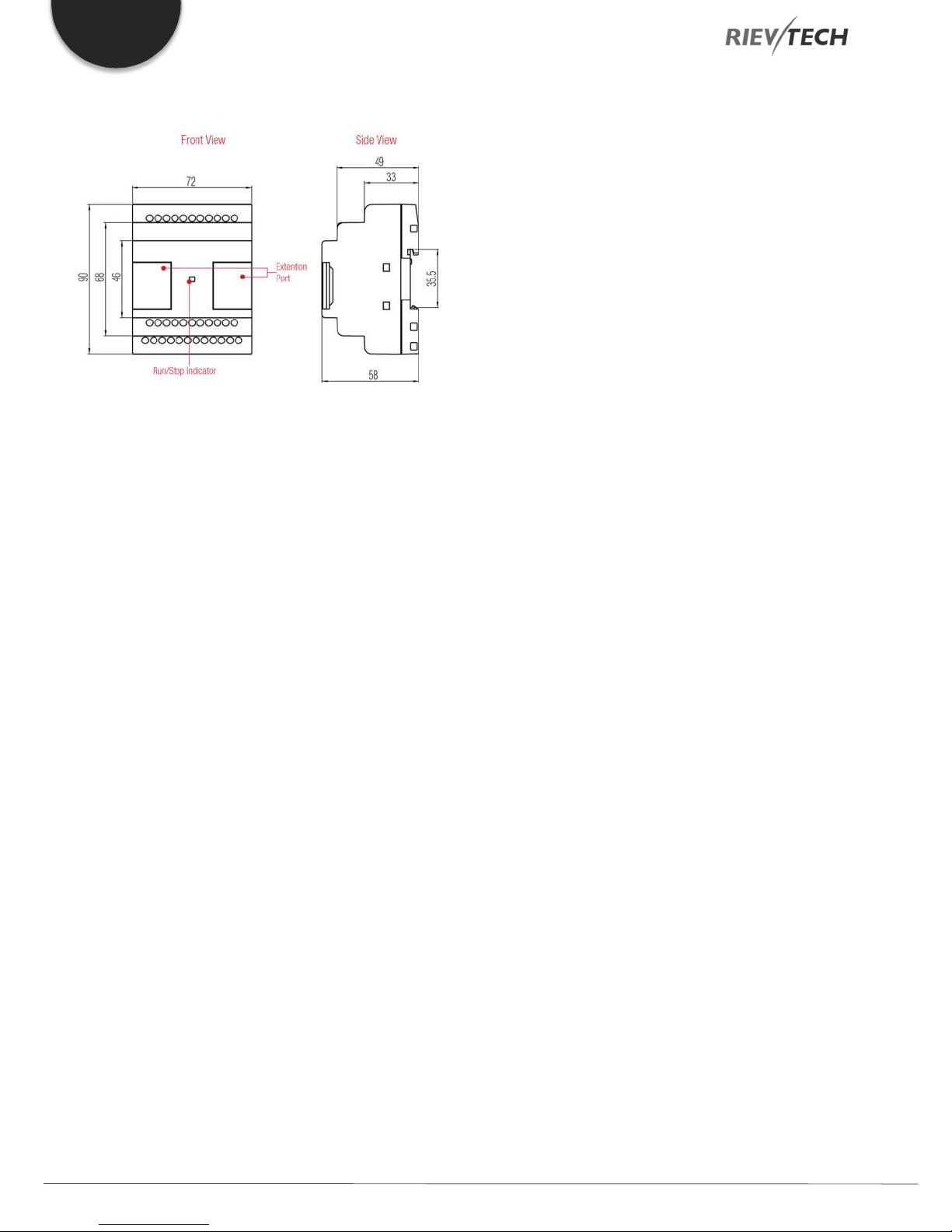
3.4. Structure & Dimensions
PR-6 Series CPU and EXM-E Expansion Modules
Figure 4 PR-6 Dimensions
PR-12 Series with LCD
PR-14 and PR-18 Series
Figure 7 PR-14 Dimensions
Figure 5 PR-12 Dimensions
PR-12 Series without LCD
Figure 6 PR-12-E Dimensions
Figure 10 PR-18 Dimensions
PR-24 Series
Figure 8 PR-24 Dimensions
Programmable Relay ● User Manual for ELC and PR Series 17 2018 v4.5 ● © Rievtech Co., Ltd. ● www.rievtech.com
EN
PR-E Expansion Modules
Figure 12 PR-E Dimensions
Programmable Relay ● User Manual for ELC and PR Series 18 2018 v4.5 ● © Rievtech Co., Ltd. ● www.rievtech.com

4. Installing and Removing Rievtech Hardware
48
EN
4.1. Dimensions
The dimensions of the Rievtech xLogic hardware is compliant
with DIN 43880.
xLogic can be “snap-mounted” to 35mm (EN 50022) DIN rail
or wall mounted.
Table 9 xLogic Dimensions
Model Width (mm)
EXM-E Expansion module
PR-6 CPU 48
PR-E Expansion module 72
PR-12 CPU 72
PR-14 CPU 95
PR-18 CPU 95
ELC-22 CPU 133
PR-24 CPU 133
8. Repeat the procedure to add further expansion units if
required.
Figure 13 Connection the CPU with expansion
NOTICE:
If you need to install the CPU and expansion units on
different DIN rails, then you will need a PR-FLAT
expansion cable. The maximum distance between
CPU and expansion unit is 200 metres.
Removing Your Hardware
Always remove power whilst adding/removing an
expansion unit.
4.2. DIN Rail Mounting
The following procedure should be used to install/uninstall you
xLogic CPUs and expansion units on DIN rail.
Mounting Your Hardware
1. Hook the top of the xLogic CPU onto the DIN rail.
2. Push down the lower end to snap it into place. The
mounting catch MUST engage.
3. Hook the top of the xLogic expansion unit onto the DIN
rail.
4. Slide the expansion unit toward the CPU until they are
touching. Make sure the ribbon cable does not get caught
between it and the CPU.
5. Push down on the lower part of the expansion unit to snap
it in place, ensuring the mounting catch engages.
6. Lift-up the expansion port cover on the CPU.
7. Push the connector of the ribbon cable into the socket on
the CPU ensuring the correct alignment of the pins and close
the cover when done.
1. Insert a screwdriver into the eyelet at the bottom of the
sliding interlock and move the latch downwards.
2. Slide the expansion module to the Right.
3. Using a screwdriver in the eyelet, carefully lever it
downward.
4. Lift the expansion unit off the DIN rail swinging the unit up
from the bottom.
5. Repeat steps 1 to 4 for all other units.
Programmable Relay ● User Manual for ELC and PR Series 19 2018 v4.5 ● © Rievtech Co., Ltd. ● www.rievtech.com

EN
4.3. Wall Mounting
For wall-mounting, first, slide the mounting slides on the rear
side of the devices towards the outside. You can now wallmount xLogic by means of two mounting slides and two M4
screws (tightening torque 0.8 to 1.2 Nm).
Drilling Templates for Wall Mounting
Use the templates below for mounting your Rievtech
hardware on a wall.
Figure 10 PR-12 Wall Mounting
Figure 11 PR-18 & Expansions Wall Mounts
Figure 9 PR-6 Wall Mounting
Figure 12 PR-24 Wall Mountings
Programmable Relay ● User Manual for ELC and PR Series 20 2018 v4.5 ● © Rievtech Co., Ltd. ● www.rievtech.com

EN
OFF/0
< 40 VAC
< 5 VDC
ON/1
> 79 VAC
> 10 VDC
Analogue Input
NOT APPLICABLE
0 to 10 VDC
Figure 13 PR-12-N Wall Mountings
Wiring
Use a screwdriver with a 3-mm blade or adjusting Rievtech
hardware terminals. You do not need wire ferrules for the
terminals. You can use conductors with cross-sections of up
to the following thicknesses:
1 x 2.5 mm2
2 x 1.5 mm2 for each second terminal chamber
Tightening torque: 0.4... .0.5 N/m (3. .4 lbs/in)
NOTICE:
Always cover the terminals after you have completed
the installation. To protect against accidental contact
with live parts. Local electrical standards must be
complied with.
Connecting Power
The following hardware is rated for operation with 110/240
VAC supply:
PR-6AC, PR-12AC, PR-14AC, PR-18AC, PR-24AC
and PR-E-16AC
The following hardware is rated for operation with 12/24
VDC supply:
PR-6DC, PR-12DC, PR-14DC, PR-18DC, PR-24DC
and PR-E-16DC
NOTICE:
A power failure may cause an additional edge
triggering signal. Only data from the last uninterrupted
cycle will be stored.
Figure 14 Power Connection
Connecting Input Signals
Inputs can be connected to various sensor elements such as
momentary switches, switches, light barriers, daylight control
switches, etc.
Table 10 Input Status
Signal state AC Type DC Type
Input Current
Input Current
NOTICE:
For PR-6DC-DA-R, PR-12DC-DA, PR-14DC-DA, PR-
18DC-DA, PR-24DC-DA Series and versions can
accept analogue inputs. The type of signal
connection can be set within the user program by
selecting ether Analogue Input or Digital Input for that
channel. They will be recognized as analogue inputs
when the input terminal is connected with an
analogue function block, otherwise, they will be
recognised as digital inputs.
< 0.03 mA
Typical 0.06 mA
< 0.1 mA
Typical 0.3 mA
Programmable Relay ● User Manual for ELC and PR Series 21 2018 v4.5 ● © Rievtech Co., Ltd. ● www.rievtech.com

EN
NOTICE:
The analogue inputs require DC 0V ~ +10V voltage
signals. These are divided equally into 0.01 VDC
increments. In programming, all the block parameters
related to the analogue inputs are based on the
minimum increment of 0.01 VDC.
NOTICE:
If the input voltage is greater than 10 VDC, they will
NOT be recognised as analogue inputs.
NOTICE:
The time taken for a change of digital state, 0 to 1 or 1
to 0, must be greater than 50ms.
DC Type Digital Input Connections
Analogue Input Connections (0 to 10 VDC)
Figure 17 Analogue Voltage Inputs
Analogue Input Connections (0 to 20 mA)
Figure 15 DC Inputs
AC Type Digital Input Connections
Figure 16 AC Inputs
Figure 18 Analogue Current Inputs
Analogue Input Connections (PT100)
Either 2 or 3-wire PT100 sensors can be connected.
With a 2-wire sensor, connect to terminals M1+ and M1-.
Short between M1+ and IC1. There is no compensation for
any impedance in the wire. A measurement error of 1 Ω is
equivalent to +2.5 °C.
Using a 3-wire sensor can inhibit any influence caused by
cable length.
Programmable Relay ● User Manual for ELC and PR Series 22 2018 v4.5 ● © Rievtech Co., Ltd. ● www.rievtech.com

Figure 19 Analogue PT100 2-, 3-Wire Inputs
Connecting Output Signals
Using a Digital Output – Relay Type
Various loads such as a lamp, fluorescent tube, motor,
contactor, etc., can be connected to the relay outputs of the
Rievtech hardware. The maximum output current that can be
handled by the relay is 10A for the resistance load and 3A for
an inductive load. The relay output connection should be wired
as per the following figure:
EN
Figure 21 Transistor Digital Output
NOTICE:
* The load connecting voltage must be ≤60 VDC and
it must be DC.
* The “+” terminal of the output wiring must be
connected to the DC positive voltage, and it must be
connected with the “L+” terminal of the CPU power
terminal. The load must be connected with the “-ve”
terminal of the DC negative voltage supply.
Figure 20 Relay Digital Output
Using a Digital Output – Transistor Type
The load connected to a transistor output
must have the following characteristics:
* The maximum switching current cannot exceed 0.3A.
* When the switch is ON (Q=1), the maximum current is 0.3A.
Using an Analogue Output
PR-E-AQ-VI (0 to 10 VDC)
Figure 22 Analogue 0-10V and 0-20mA Output
EXM-E-RS485/PR-RS485
The RS485 expansions are just converters with photo isolation
providing 3-sets of wiring terminals (although there are 3-sets
of terminals, they are connected within the unit, so only one
channel RS485 is available) of RS485 port (2x8pin) of
CPU(PR-18/ELC-22/PR-24) for easy connection with other
devices.
Programmable Relay ● User Manual for ELC and PR Series 23 2018 v4.5 ● © Rievtech Co., Ltd. ● www.rievtech.com

EN
Figure 23 RS485 Connection
If “RT1”, RT2” terminals are short connected, one 120R
resistor will be connected between A/+ and B/- providing a
termination resistor for end-of-line purposes.
Communication Port Instructions
PR-6 CPUs
Figure 24 PR-6 CPU Ports
Without HMI
PR-14, PR-18, ELC-22 and PR-24 CPUs
PR-12 CPUs
Figure 25 Other CPU Ports
The programming port/RS232 port can be used with any of
the following Rievtech devices. ELC-RS232, ELC-USB, ELCCopier, ELC-MEMORY, ELC-BATTERY, and PRO-RS485.
This is COM 0.
With HMI
Programmable Relay ● User Manual for ELC and PR Series 24 2018 v4.5 ● © Rievtech Co., Ltd. ● www.rievtech.com
When the programming port is being used as the standard
RS232 port (D-shape 9 pin header). The ELC-RS232 cable is
needed. Below shows you the pinouts for the device:

EN
PIN
Function
2
RXD
3
TXD
5
GND
others
NULL
PR-RS485 module is required when either the PR-18/ELC22/PR-24 CPU is required to communicate with a third-party
device via RS485. Note the PR-24 has a built-in RS485 too.
Figure 26 RS232 Pinouts
Expansion port/RS485 (pin definition)
Figure 34 RS485 Pinouts
3------RS485 A 7------CANL
5------RS485 B 9------CANH
4------GND 15------+5V
6------GND 16------+5V
Communication between CPU and expansion module will
use pins 4, 7, 9 and 15.
Figure 27 COM Port Details on LCD
The programming port/RS232 port can be used with any of
the following Rievtech devices. ELC-RS232, ELC-USB, ELCCopier, ELC-MEMORY, ELC-BATTERY, and PRO-RS485.
This is COM 0.
When the programming port is being used as the standard
RS232 port (D-shape 9 pin header). The ELC-RS232 cable is
needed.
Programmable Relay ● User Manual for ELC and PR Series 25 2018 v4.5 ● © Rievtech Co., Ltd. ● www.rievtech.com
EN
5. Parameter Modification using CPU HMI
5.1. Overview of CPU Menu Structure
The PR-12, PR-14, PR-18, ELC-12-N and ELC-22-N have the
same menu structure. We will use a PR-18 in the following
examples.
Parameter Assignment Mode
Parameter assignment menu:
Figure 28 CPU Parameter Menu
5.2. LCD Panel Instructions
This panel allows the user to carry out the following tasks:
Display the RUN/STOP status of the CPU
Display/modify the Clock
Display IO status of CPU and expansion units
Display alarm messages
Display program register values
Modify some types of register parameters
Control of backlight using the program, Light on
Alarm for example
Initial system display message can be customized
Up to 64 different alarm messages can be displayed
Modify the CPU ID address
Set password protection
Change communication parameter for COM ports
PR-12 Series CPU
PR-18 Series CPU
ELC-22 and ELC-26 series CPU
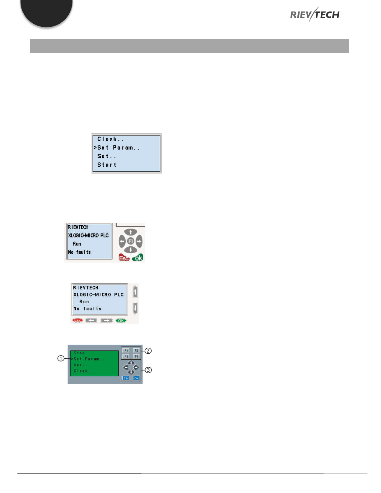
1. Display Area – 4 x 16 characters can be displayed
2. 4 Function Keys – Only on models ELC-22-N and PR-24
Series CPUs.
3. 6 Panel Keys – Used to navigate menu and view alarm
messages.
Programmable Relay ● User Manual for ELC and PR Series 26 2018 v4.5 ● © Rievtech Co., Ltd. ● www.rievtech.com

LCD Menu Structure
EN
Programmable Relay ● User Manual for ELC and PR Series 27 2018 v4.5 ● © Rievtech Co., Ltd. ● www.rievtech.com

EN
Figure 29 LCD Menu Structure
After being powered on, the CPU will check to see if a valid
program is stored within it.
If the program is accurate, then the CPU will be running,
meanwhile, the system cover will show as follows, this can be
customised within xLogicsoft, this is the default initialization
screen.
If there are several parameter pages, users can press or
keys to go to the page they require. The last page is the
cursor mode:
Cursor keys can be controlled in this page by pressing arrow
keys and ESC key at the same time.
If xLogic has several alarms in the same period, it only displays
the message with the highest priority in the function block. You
may cycle through all current alarm messages by pressing
or key.
NOTICE:
The message text block within xLogicsoft is treated as
a parameter page only when it has no input
connected to it, otherwise, it will be regarded as an
alarm page. When the input pin sees a rising edge,
the LCD will display an alarm message.
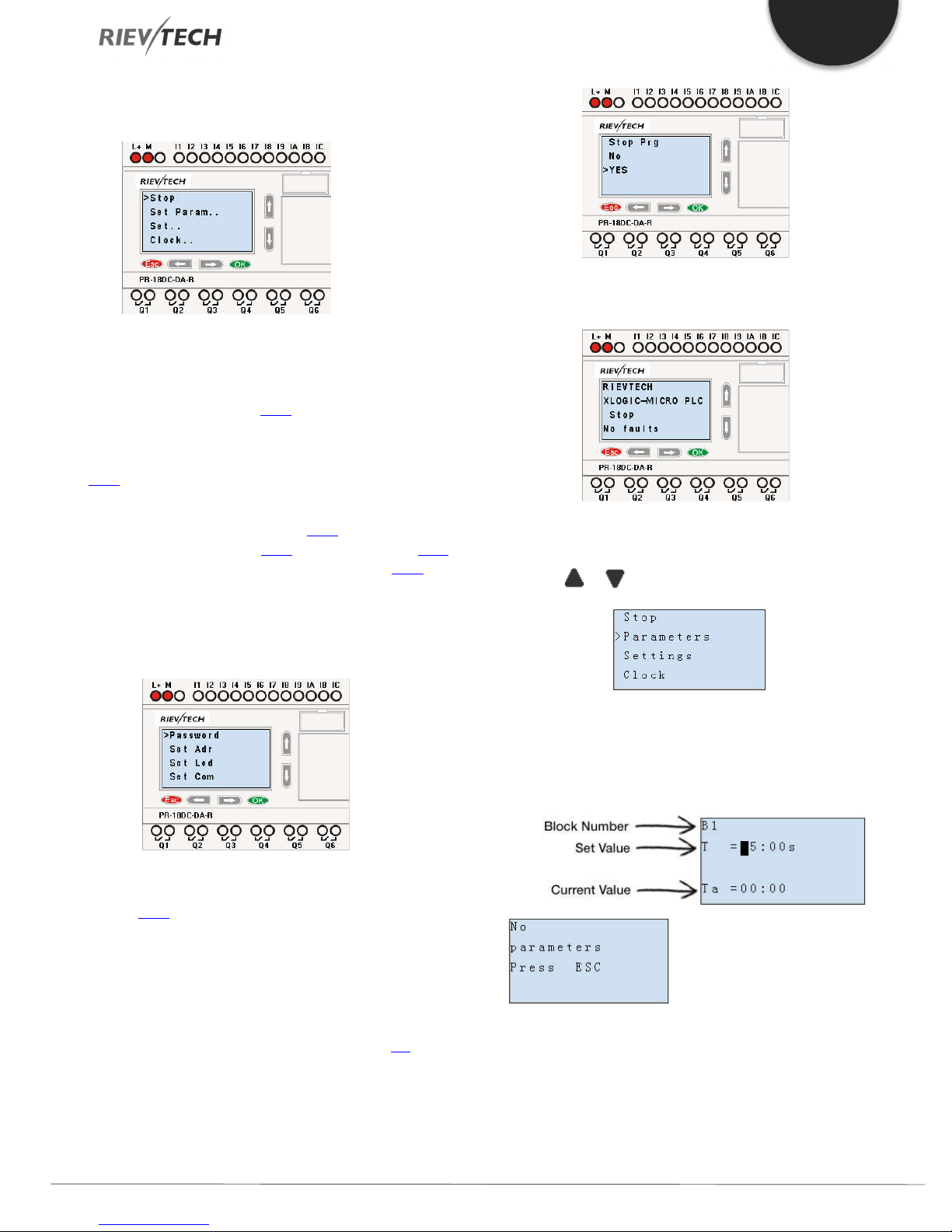
5.3. Selecting a Function Page
Press ESC key to change from running mode to function page
mode.
Programmable Relay ● User Manual for ELC and PR Series 28 2018 v4.5 ● © Rievtech Co., Ltd. ● www.rievtech.com
After pressing ESC key, xLogic switches to function page and
the function menu will be shown as below.
Function Page Options
Run/stop
Select this menu to switch the xLogic status between RUN
and STOP. Refer to chapter 4.3.1 for details.
Set Param
To set/change a function block parameter. Refer to chapter
4.3.2 for details.
Set…
Used to set/modify a password (see 4.3.3), set an address of
CPU or expansion unit (see 4.3.4), LCD settings (see 4.3.5)
and communication parameters settings (see 4.3.6) for
details.
1. Press ”UP” or “DOWN” key to move the cursor to
“Set….”
2. Then press the OK key, xLogic will display as follows:
EN
After pressing ESC key, you’ll find out your program has
changed to “stop” status as shown below:
Set Parameter
1. Under the FUNCTION PAGE, select “Parameters”:
Press or key
Clock
To set and modify date and time. Refer to
chapter 4.3.7 for details.
Network (This only for Ethernet CPU)
Recovery ET: Pressing OK whilst the cursor is on this option
will be reset the CPU to default settings.
How to Switch Between RUN and STOP
You should first select a FUNCTION PAGE. (Read 4.3)
1. Move the cursor to “Run/stop”: Press “UP” or “DOWN”
key.
2. Move the cursor to "Yes": Press OK key.
2. Confirm by pressing the OK key.
Then xLogic displays the first parameter, so you can modify
as you like. If there is no parameter to set/modify, you can
press ESC key to return.
No parameter to edit, press
ESC key to return
3. Select the parameter you intend to modify.
4. Select a specific value of that parameter which you want
to edit, then press the OK key.
Programmable Relay ● User Manual for ELC and PR Series 29 2018 v4.5 ● © Rievtech Co., Ltd. ● www.rievtech.com
EN
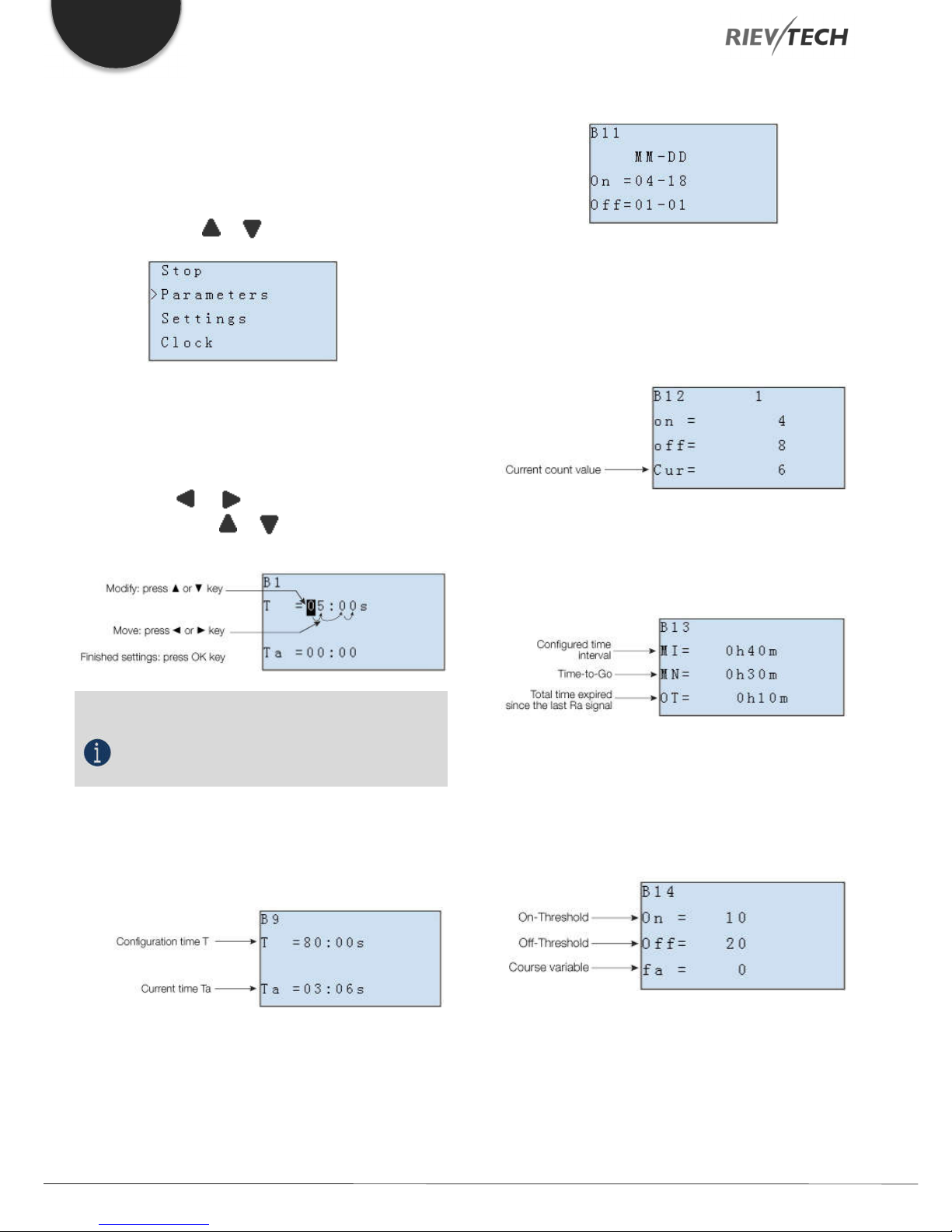
How to modify parameter?
A. First, select a parameter which you need to edit by following
the procedures below:
1. Under the FUNCTION PAGE, select
“Parameters”: Press or key
2. Confirm by pressing the OK key.
B. Move to the parameter, modify value and
press OK to confirm:
1. Move the cursor to the parameter to be
modified: press or key.
2. Modify value: press or key.
3. Confirm the modification by pressing the OK
key.
In parameter mode, time segment figure of a timer:
You can alter the time and date of the on/off switch.
The current value of the counter
In parameter mode, the parameter view of a counter:
The current value of hour counter
In parameter mode, the view of the hour counters:
NOTICE:
When xLogic is running, not only the time value but
also the units of time (S, M, H) can be altered. You
can alter the time base (s=second, m=minute,
h=hour) during runtime.
The current value of time T
View time T in parameter mode:
You can modify the configuration time or switch on/off time
for a particular time segment.
You can edit configured time interval (MI).
The current value of the threshold trigger
In parameter mode, the view of threshold trigger:
You can alter the threshold values for on/off.
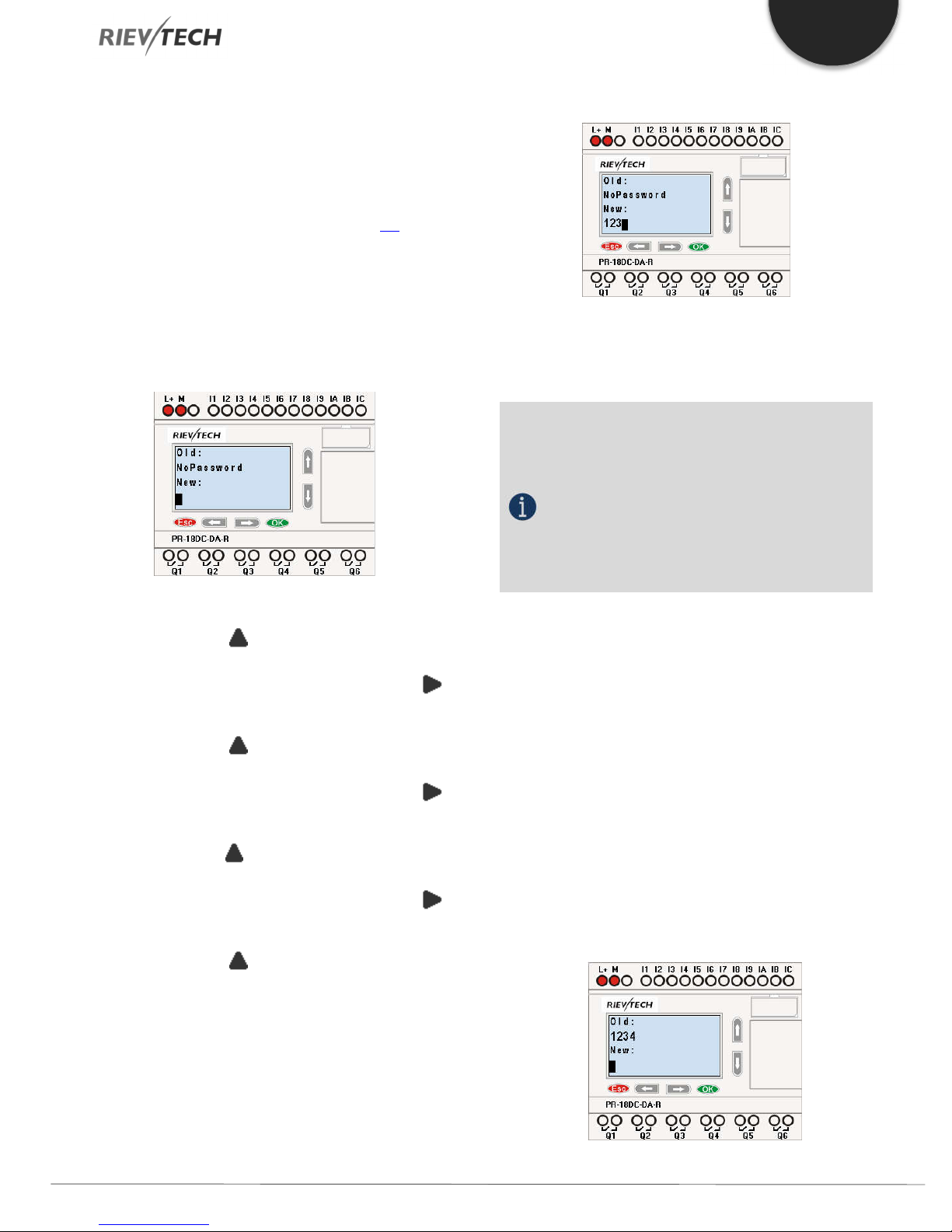
Set Password
You can set a password to protect your program within the
xLogic CPU.
Programmable Relay ● User Manual for ELC and PR Series 30 2018 v4.5 ● © Rievtech Co., Ltd. ● www.rievtech.com
EN
Set a new password:
A password contains up to 4 characters and each character
is a number from 0 to 9. You can specify, edit or remove a
password directly in xLogic using the “Password” menu of the
function page:
You should first select a FUNCTION PAGE. (Read 4.3)
1. Move the cursor to “Password” by pressing the “UP” or
“DOWN” key.
2. Confirm “Password”: Press OK key.
Example: Let’s set “1234” as the password for a program.
Now the LCD displays the following interface:
Select “New” option, and then edit it.
Now display:
10. Confirm password: press OK key.
Now, the program is protected by the password of “1234”,
and then you can return to the main menu.
NOTICE:
You can cancel a password newly-set by pressing the
ESC key. In this instance, xLogic will return to the
main menu without saving the password. This
password protects unauthorised changes to ay
parameters, which means that to make any changes
via the LCD, the password is required. The program
password should be set in xLogicsoft by the menu
File->Property-> Parameter to protect the program
itself from unauthorised changes/copying.
3. Select “1”: press “UP” key once.
4. Move the cursor to the next character: press “Right”
key.
5. Select “2”: press “UP” key twice.
6. Move the cursor to the next character: press “Right”
key.
7. Select”3”: press “UP” key three times.
8. Move the cursor to the next character: press “Right”
key.
9. Select “4”: press “UP” key four times.
Modify password:
To modify the password, you are required to enter the current
password first.
In the menu of the FUNCTION PAGE:
1. Move the cursor to “Password”: Press “UP” or “DOWN”
key.
2. Confirm “Password”: Press OK key.
Select “Old” and input current password (in our instance is
“1234”), the process is the same as the step 3 to step 10
mentioned above.
LCD displays:
Programmable Relay ● User Manual for ELC and PR Series 31 2018 v4.5 ● © Rievtech Co., Ltd. ● www.rievtech.com

EN
Select “New” to input new password such as “8888”:
3. Select “8”: press “UP” key.
4. Move the cursor to the next character: press “Right” key.
Repeat the step 3 and 4 to enter the third and fourth
characters.
LCD displays:
5. Confirm new password by pressing the OK key.
How to remove the password:
If you need to remove the password e.g. allow the other users
to edit your program, then you must know the current
password. The process for removing a password is the same
as that for modifying it.
In the menu of the FUNCTION PAGE:
1. Move the cursor to “Password”: Press “UP” or “DOWN”
key.
Password settings in xLogicsoft.
The menu File->Properties (Parameter)
2. Confirm “Password”: Press OK key.
Select “Old” and input current password (in our instance is
“8888”), the process is the same as the step 3 to step 10
mentioned above.
LCD displays as follows:
Input nothing under the “New” and press OK to clear the
password.
4. Confirm “blank” password: press OK key. Now you have
cleared the password and can return to the main menu. If you
want to set a password next time, repeat steps above in 4.3.3.
There are 2 password settings which can be applied to the
program, one is the program password and the other is the
parameter password.
Program password:
If you set the program password, then the password is
required when you want to upload the program to PC.
Parameter password:
If you set the parameter password, then the
password is required when you want to change
parameters via the LCD.
Programmable Relay ● User Manual for ELC and PR Series 32 2018 v4.5 ● © Rievtech Co., Ltd. ● www.rievtech.com

EN
NOTICE:
1.The password which can be set in the LCD menu is
the parameter password.
2.The program password cannot be set in the LCD
menu, it can only be set in xLogicsoft.
How to Set the Address of a CPU and Expansion
Modules
Setting the CPU Address
If there is more than one CPU in a communication network,
then the address of each CPU must be different. You can
change the address of CPU via xLogicsoft or via the panel key
if the CPU with LCD panel. The address range is from 1 to 247
for ELC and PR series CPUs.
You can set the CPU address by the menu Tools-> transfer->
set PLC’s address in xLogicsoft.
Confirm with "OK"
Change the address with arrow keys and confirm
with "OK".
The CPU address can also be set by xLogicsoft if the CPU is
without HMI.
Set Address of PR-Expansions. (PR-E-16DC-DA-R, etc.)
Plastic Cover
Using a screwdriver, remove the plastic cover and to reveal
dip switches.
Set the dip switches to achieve the address you require as
detailed below.
Up to 16 expansion units (includes IO, AQ, AI, PT100 modules)
can be connected to the CPU.
Figure 30 Expansion Address Dip Switches
Programmable Relay ● User Manual for ELC and PR Series 33 2018 v4.5 ● © Rievtech Co., Ltd. ● www.rievtech.com
The default address of PR-E expansions is 1 and the dip
switches are set as below ( means the switch position):
Address 1: Address 2: Address 3:

EN
Address 4: Address 5: Address 6:
Address 7: Address 8: Address 9:
Address 10: Address 11: Address 12:
Address 13: Address 14: Address 15:
Address 16:
2. Select “Set LCD” menu and click “OK”
3.Select "Backlight” menu and click "OK"
NOTICE:
1. The expansion unit address MUST be set before
power is applied otherwise the settings will not take
effect.
2. You can freely mix both AC and DC CPUs and
expansion units.
3. If the communication is established between CPU
and expansion units, the LED indicator on the top of
the expansion units will turn to RUN (Green). (If the
LED is red, it means the CPU cannot communicate
with it).
4. If more than one expansion module is connected to
CPU at the same time, the address of each
expansion module must be different from each other,
otherwise, the system (CPU + expansions) would run
abnormally. As long as each expansion unit has a
unique address, they can be connected in any order
whatsoever.
Setting LCD Backlight and Contrast
The backlight of CPU can be set with an “ON” time of 10
seconds or “ON” all the time. This is set as follows:
1. Select “Set...” menu and click OK.
4. The default is 10 seconds, and another option is "Always
On". Confirm with "OK"
Modify the contrast
Confirm with "OK"
Programmable Relay ● User Manual for ELC and PR Series 34 2018 v4.5 ● © Rievtech Co., Ltd. ● www.rievtech.com

EN
Modify the contrast with Left or Right key and
confirm with "OK".
Set Communication Parameters
Select "Set Com" menu from the menu "Set...”.
Confirm with "Ok"
Confirm with "OK"
Change it by pressing Up and Down keys.
And confirm with "OK"
Set Modbus Protocol
COM0: RS232 port or programming port.
COM1: RS485 port (For the PR-RS485 expansion module
when connected to PR-14, PR-18, PR-24, ELC-18, ELC-22,
ELC-26 CPU)
COM2: Built-in RS485 port for PR-14 and PR-24 CPU.
COM3: Ethernet port for ELC-22-N CPU, reserved for other
series CPU.
Confirm with "OK"
Figure 31 Set Modbus Port
Programmable Relay ● User Manual for ELC and PR Series 35 2018 v4.5 ● © Rievtech Co., Ltd. ● www.rievtech.com

EN
Change with the Up and Down keys and confirm with "OK"
There are 4 options available: RTU, ASCII, TCP RTU, TCP
ASCII.
NOTICE:
If you want to use the Modbus TCP protocol, select
the "TCP RTU".
Setting System Date and Time
You should first select the FUNCTION PAGE. (see 15.1)
1. Move the cursor to “Clock” by pressing “UP” or “DOWN”
key.
2. Confirm “Clock”: Press OK key.
Figure 32 Set Date and Time
To set the time, move the cursor to” Set Time” menu, then
press the OK key.
Here you can set the weekday (From Monday to Sunday) and
the clock. The method is setting the time. After completion of
your setup, press OK key:
Press OK key to set and modify date.
Press “UP” or “DOWN” key to change the date to what you
want to set. After you have finished your setting, press OK
key to return to Date/Time menu.
Press ESC key and return to FUNCTION PAGE.
Programmable Relay ● User Manual for ELC and PR Series 36 2018 v4.5 ● © Rievtech Co., Ltd. ● www.rievtech.com

6. Configuring and Programming Rievtech Hardware
EN
Programming your hardware is done using the xLogicsoft
software package, which is FREE and designed to be installed
on a Windows PC. The software utilises a method of
programming called Function Block Diagrams (FBD). FBD is
an easy to use and user-friendly programming environment. A
program is created by dropping pre-programmed blocks onto
a workspace area and connecting the blocks together to
create your control program.
The xLogicsoft programming software allows the user to
create a self-documenting, user-friendly program and to
simulate your program on your PC without the need for a
Rievtech PLC. Here are some of the features available in
xLogicsoft software:
Modern graphical block representation.
A friendly graphical user interface for the creation of
your circuit program by use of FBD blocks.
Off-line simulation of your logic on your PC.
Automatic generation of chart documentation for
printing.
Ability to add comments to your circuit program.
Download and upload your program to/from your
Rievtech PLC CPU.
On-line debug mode allowing you to view the status
of inputs and outputs, block values and timer values.
Ability to Start and Stop your program via the PC.
Ability to create your own blocks from the standard
blocks available.
6.1. xLogicsoft Functions
The ELC and PR-Series of Rievtech CPUs can be
programmed using FBD, which includes a variety of preconfigured function blocks:
16 Co - Constant Blocks
9 GF - Basic Function Blocks
49 SF - Special Function Blocks
15 AP – App Function Blocks
MQ – MQTT Function Blocks
Add Your Own Library Blocks
By adding these blocks to your program and linking them
together, you can create relatively complex control programs.
This manual will describe each available block in detail in the
following sections.
Blocks are placed into your work area by selecting them from
the left-hand block list in xLogicsoft and clicking anywhere in
your workspace to the right of the block list.
Blocks are connected to each other by clicking on either the
input or output pin of the block (a chain icon will appear) and
without releasing the mouse button, drag the connector to the
block-pin you wish to link to (a chain icon will appear), then let
go of the mouse button. We are continuingly adding features
to our software and should you need a new special function
block which currently does not exist in xLogicsoft, then let us
know and we will look at adding it. Contact:
technical@rievtech.com.
Programmable Relay ● User Manual for ELC and PR Series 37 2018 v4.5 ● © Rievtech Co., Ltd. ● www.rievtech.com

EN
PR-6
4
PR-12
8
PR-14
74
PR-18
76
ELC-22
78
PR-24
78
6.2. General Input and Output Functions
Digital Input
Digital input blocks represent the physical digital input
terminals of your Rievtech CPU and expansion units if fitted.
The following table list the maximum number of digital inputs
that a CPU can support.
Table 11 Maximum Digital Inputs per CPU
CPU
To configure a digital input block which has been placed in
your workspace, double-click on it to open the blocks
configuration options.
MAXIMUM DIGITAL INPUTS
Cursor keys
Up to four cursor keys are available to you. Cursor keys are
programmed for the circuit program in the same way as other
inputs. Cursor keys can save switches and inputs and allow
operator control of the circuit program.
Switch the screen to the current page (above shows) by
pressing the Left or Right key, and press ESC key and arrow
keys at the same time, then the corresponding cursor keys
will turn on and give off a high trigger!
Digital Output
Figure 40 - Digital Input Block Configuration
If the input is on the main CPU then you can select it using the
Input drop-down box. Only available inputs will be shown.
If the digital input is in an expansion module, then select the
radio button for Ext. Module and use the drop-down box to
select which expansion block number, followed by the digital
input number.
NOTICE:
I12 means digital input 2 on expansion address 1, I81
means digital input 1 on expansion address 8.
Output blocks represent the output terminals of xLogic. You
can use up to 2 outputs (ELC-6), 4 outputs (PR-12),70 outputs
(PR-18), 72 outputs (PR-22), 74 outputs (PR-26). In your block
configuration, you can assign an output block to a new
terminal, provided this terminal is not already used in your
circuit program.
The output always carries the signal of the previous program
cycle. This value does not change within the current program
cycle.
NOTICE:
Q11 means the Q1 output of the expansion with
address 1.
Q85 means the Q5 output of the expansion with
address 8.
Permanent Logical Levels HI and LO
Set the block input to logical hi (hi = high) to set it permanently
to logical '1' or 'H' state.
Programmable Relay ● User Manual for ELC and PR Series 38 2018 v4.5 ● © Rievtech Co., Ltd. ● www.rievtech.com

Set the block input to logical lo (lo = low) to set it permanently
to logical '0' or 'L' state.
Panel Key
It is the symbol for the Function key on the CPU panel (F1—
F4) where fitted. If one of the function keys is pressed down,
the status of the corresponding symbol in the program shall
turn from 0 to 1. This will give off one high trigger.
EN
You can use up to 36 analogue inputs. In your block
configuration, you can assign a new input terminal to an input
block, provided this terminal is not already used in the circuit
program.
NOTICE:
1. Only one function key can be pressed down at any
one time. If you press down two or more at the same
time, xLogic will not process the keystrokes.
2. If the arrow keys (UP, DOWN, LEFT and RIGHT),
Esc and OK had been applied to the program, then
they would be invalid for menu operation (e.g. manual
programming, parameters modification and view
alarming message etc).
Shift Register Bits
For help on analogue block parameter, refer to Information on
analogue value processing.
NOTICE:
AI11 means the AI1 input of the expansion with
address 1.
AI82 means the AI2 input of the expansion with
address 8.
Based on different analogue input signals, you need select a
different sensor type in the analogue blocks, you need to use
an analogue amplifier with the AI input, and select the
corresponding sensor type for DC0.10V, 0/4.20mA or PT100
input.
xLogic provides the shift register bits S1 to S8, which are
assigned the read-only attribute in the circuit program. The
content of shift register bits can only be modified by means of
the Shift register special function
Analogue Inputs
Programmable Relay ● User Manual for ELC and PR Series 39 2018 v4.5 ● © Rievtech Co., Ltd. ● www.rievtech.com
F (Digital Flag)
Flags are used when xLogic works in a communication
system. F is a digital flag which is used to save /transfer signal
1 or 0 (data format is Bit) and AF is an analogue flag which is

EN
used to save /transfer analogue values (data format is Signed
short) between the master and slave devices. Up to 32 (ELC-
6), 128 (PR-12/ELC-22/ELC-26) can be used when
programming. In your block configuration, you can assign a
new number to the flag, provided this flag number does not
already exist in your circuit program.
The output always carries the signal of the previous program
cycle. This value does not change if the communication has
failed.
Start-Up Flag: F8
The F8 flag is set in the first cycle of the user program and can
thus be used in your circuit program as a start-up flag. It is
reset after the first program execution cycle.
In the subsequent cycles, the F8 flag reacts in the same way
as the F1 to F64 flags.
Backlight Flag: F64
The F64 flag controls the backlight of the xLogic display or the
ELC-43T backlight. You can use the outputs of timers,
message texts, or other function blocks to activate the
backlight flags. To enable multiple conditions to control the
backlight of the devices, you can use multiple function blocks
in parallel or in sequence. Buzzer of ELC-43TS control flag:
F63
NOTICE:
1. The address of “F“ can be found in the Modbus
communication protocol file. The F block figure must
have the input pin in the xLogic showing.
2. Keep the input pin of F NULL (do not connect with
other blocks) if you want to use the write property.
AF (Analogue Flag)
Flags are used when xLogic works in a communication
system. AF is an analogue flag which is used to save /transfer
analogue values (data format is Signed short) between the
master and slave devices. Up to 32 (PR-6) and 256 (PR12/PR-18/PR-24) for xLogic CPU can be used when
programming. In your block configuration, you can assign a
new number to the analogue flag, provided this flag number
does not already exist in your circuit program.
The output always carries the signal of the previous program
cycle. This value does not change if the communication were
to fail.
NOTICE:
1. The address of “AF“ can be found in the Modbus
communication protocol file.
2. Keep the input pin of AF NULL (do not connect
with other blocks) if you want to use the Write
property.
You can set a start value for the AF1—AF64 (PR-12/PR18/PR-24), and the value does not get lost if the power was a
failure, so you can use such AF in your program as a number
input from the touchscreen or the panel key of the CPU.
NOTICE:
1. AF65--AF256 does not support a Start Value
function, and the values of AF65 to AF256 will be lost
if the power fails.
2. If you enable the "start value option" of AF, then
you are not allowed to connect any other function to
the input leg of the AF.
3. If you connect the input leg of the AF block to other
function blocks, the "start value" will not be available
anymore.
Programmable Relay ● User Manual for ELC and PR Series 40 2018 v4.5 ● © Rievtech Co., Ltd. ● www.rievtech.com
EN
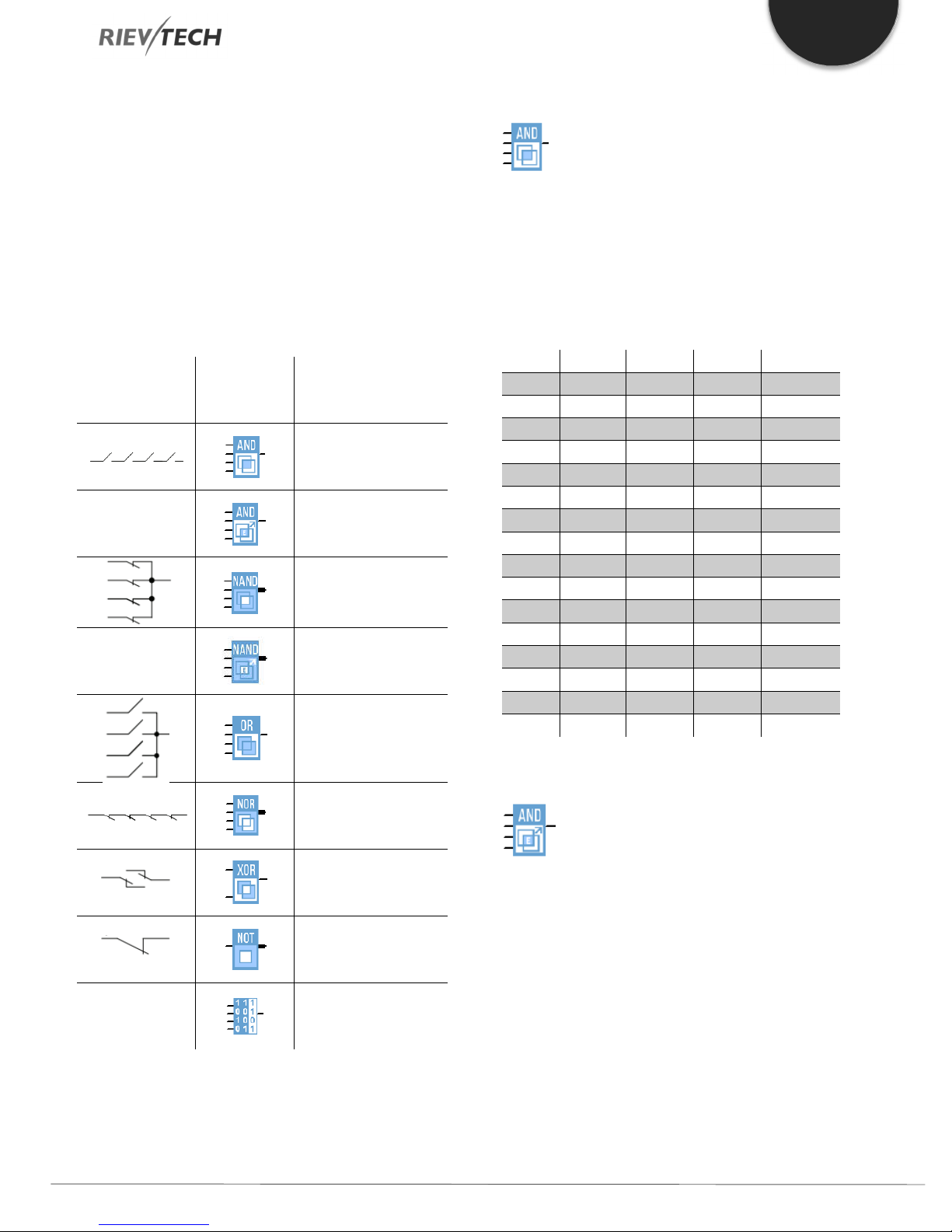
6.3. Basic Functions List – GF
Basic functions represent simple logical elements of Boolean
algebra.
You can invert the inputs of individual basic functions, i.e. The
circuit program inverts a logical “1” at a relevant input to a
logical “0”; if “0” is set at the input, the program sets a logical “1”
and vice versa.
The GF list contains the basic function blocks you can use for
your circuit program. The following basic functions are available:
Table 12 Basic functions
View in the
circuit diagram
View in
xlogicsoft
Name of the basic
function
AND
AND with edge
evaluation
NAND (Not AND)
NAND with edge
evaluation
OR
AND
Description of function
The output of an AND function is only 1 if all inputs are 1, i.e.
when they are closed.
A block input that is not used (x) is assigned: x = 1.
Table 13 AND Block Logic
Input1 Input2 Input 3 Input 4 Output
0 0 0 0 0
0 0 0 1 0
0 0 1 0 0
0 0 1 1 0
0 1 0 0 0
0 1 0 1 0
0 1 1 0 0
0 1 1 1 0
1 0 0 0 0
1 0 0 1 0
1 0 1 0 0
1 0 1 1 0
1 1 0 0 0
1 1 0 1 0
1 1 1 0 0
1 1 1 1 1
AND with Edge Evaluation
BOOLEAN
FUNCTION
Programmable Relay ● User Manual for ELC and PR Series 41 2018 v4.5 ● © Rievtech Co., Ltd. ● www.rievtech.com
NOR (Not OR)
XOR (exclusive OR)
NOT (negation,
inverter)
BOOLEAN FUNCTION
Description of function
The output of an AND with edge evaluation is only 1 if all inputs
are 1 and at least one input was 0 during the last cycle.
The output is set to 1 for the duration of one cycle and must
be reset to 0 for the duration of the next cycle before it can be
set to 1 again.
A block input that is not used (x) is assigned: x = 1.

EN
0 0 0 0 1
0 0 0 1 1
0 0 1 0 1
0 0 1 1 1
0 1 0 0 1
0 1 0 1 1
0 1 1 0 1
0 1 1 1 1
1 0 0 0 1
1 0 0 1 1
1 0 1 0 1
1 0 1 1 1
1 1 0 0 1
1 1 0 1 1
1 1 1 0 1
1 1 1 1 0
0 0 0 0 0
0 0 0 1 1
0 0 1 0 1
0 0 1 1 1
0 1 0 0 1
0 1 0 1 1
0 1 1 0 1
0 1 1 1 1
1 0 0 0 1
1 0 0 1 1
1 0 1 0 1
1 0 1 1 1
1 1 0 0 1
1 1 0 1 1
1 1 1 0 1
1 1 1 1 1
The timing diagram of an AND with edge evaluation
NAND
Description of function
The output of a NAND function is only 0 if all inputs are 1, i.e.
when they are closed.
A block input that is not used (x) is assigned: x = 1.
The output of a NAND with edge evaluation is only 1 at least
one input is 0 and all inputs were 1 during the last cycle.
The output is set to 1 for the duration of one cycle and must
be reset to 0 at least for the duration of the next cycle before
it can be set to 1 again.
A block input that is not used (x) is assigned: x = 1.
The timing diagram of a NAND with edge evaluation
OR
Table 14 NAND Block Function
Input1 Input2 Input 3 Input 4 Output
Description of function
The output of an OR is 1 if at least one input is 1 (closed).
A block input that is not used (x) is assigned: x = 0.
Table 15 OR Block Logic
Input1 Input2 Input 3 Input 4 Output
NAND with Edge Evaluation
Description of function
Programmable Relay ● User Manual for ELC and PR Series 42 2018 v4.5 ● © Rievtech Co., Ltd. ● www.rievtech.com
EN
0 0 0 0 1
0 0 0 1 0
0 0 1 0 0
0 0 1 1 0
0 1 0 0 0
0 1 0 1 0
0 1 1 0 0
0 1 1 1 0
1 0 0 0 0
1 0 0 1 0
1 0 1 0 0
1 0 1 1 0
1 1 0 0 0
1 1 0 1 0
1 1 1 0 0
1 1 1 1 0
0 0 0
0 1 1
1 0 1
1 1 0
0
1
0
0
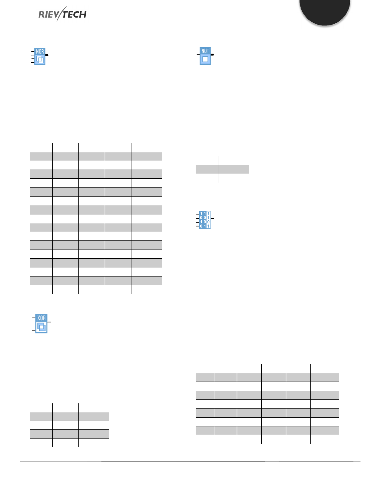
NOR
Description of function
The output of a NOR (NOT OR) is only 1 if all inputs are 0, i.e.
when they are open. When one of the inputs is switched on
(logical 1 state), the output is switched off.
A block input that is not used (x) is assigned: x = 0.
Table 16 NOR Block Logic
Input1 Input2 Input 3 Input 4 Output
NOT
Description of function
The output is 1 if the input is 0. The NOT block inverts the input
status.
The advantage of the NOT, for example, xLogic no longer
requires break contacts. You simply use a make contact and
convert it into a break contact with the help of the NOT
function.
Table 17 NOT Function Logic
Input1 Output
Boolean Function
XOR
Description of function
The XOR (exclusive OR) output is 1 if the signal status of the
inputs is different.
A block input that is not used (x) is assigned: x = 0.
Table 17 XOR Function Logic
Input1 Input2 Output
Description of function
The BOOLEAN function gives the value of the output
according to the combination of inputs.
The function has four inputs, and therefore 16 combinations.
These combinations can be found in a truth table; for each of
these, the output value can be adjusted. The number of
configurable combinations depends on the number of inputs
connected to the function.
Non-connected inputs are set to 0.
The following diagram shows an example of part of the
Boolean function truth table:
Table 18 Boolean Function Logic (Example of Output states)
Index Input1 Input2 Input 3 Input 4 Output
1 0 0 0 0 1
2 0 0 0 1 1
3 0 0 1 0 1
4 0 0 1 1 0
5 0 1 0 0 1
6 0 1 0 1 1
7 0 1 1 0 1
8 0 1 1 1 1
Programmable Relay ● User Manual for ELC and PR Series 43 2018 v4.5 ● © Rievtech Co., Ltd. ● www.rievtech.com

EN
A signal at input S sets the output
The reset input R takes priority over
This input is used to trigger the
Cnt
This input is used for counting
Fre
Frequency signals to be evaluated
Dir
This input determines the direction
En (Enable)
This input enables a block function.
A signal at this input inverts the
Ral (Reset
9 1 0 0 0 1
10 1 0 0 1 0
11 1 0 1 0 0
12 1 0 1 1 0
13 1 1 0 0 0
14 1 1 0 1 1
15 1 1 1 0 0
16 1 1 1 1 0
Parameters
Having connected at least one input, you can configure the
value of the output in the truth table, in the Parameters
window.
The output values can be 0 for the Inactive state, and 1 for the
Active state (Double click to change the 0 or 1).
By selecting the Output ON if the result is TRUE, the output
takes the value configured in the truth table.
By selecting the Output OFF if the result is TRUE, the output
takes the inverse value of the value configured in the truth
table.
Table 19 Logical Input types
Name Description Image
S (Set)
R (Reset)
Trg (Trigger)
(Count):
(Frequency)
(Direction)
or
Validation
Inv (Invert)
all):
Value Integer value
all other inputs and resets the
When this input is “0”, other signals
to logical “1”.
outputs.
start of a function.
are applied to this input.
of count.
to the block will be ignored.
output signal of the block.
All internal values are reset.
pulses.
-
-
Parameter inputs
For some of the inputs, you do not apply any signals. You
configure the relevant block values instead. Examples:
6.4. Basics of Special Functions - SF
Because of their different input designation, you can see right
away that there is a difference between the special functions
(SF) and basic functions. SF’s contain timer functions, retentive
functions and various parameter assignment options, which
allow you to adapt the circuit program to suit your own
requirements.
This section provides you with a brief overview of input
designations and with some particular background
information on SF’s. The SF’s, in particular, are
described in Chapter 5.5
Designation of the Inputs to Blocks
Logical inputs
Here, you will find the description of the connectors you can
use to create a logical link to other blocks or to the inputs of the
xLogic unit.
Par (Parameter):
This input will not be connected. Here, you set the relevant
block parameters (times, on/off thresholds etc.).
No (Cam):
This input will not be connected. Here, you configure the time
patterns.
P (Priority):
This is an open input. Here, you define priorities and specify
whether a message is to be acknowledged during RUN time.
Time Response
Parameter T
In some of the SFs it is possible to configure a time value T.
When you pre-set this time, your input values are based on
the time base set:
Time base -- : --
s (seconds) Seconds : 1/100 seconds
m (minutes) Minutes : seconds
h (hours) Hours : minutes
Programmable Relay ● User Manual for ELC and PR Series 44 2018 v4.5 ● © Rievtech Co., Ltd. ● www.rievtech.com

EN
Accuracy of T
Because of slight tolerances in the characteristics of electronic
components, the set time T may deviate. The xLogic has a
maximum tolerance of ± 0.02 %. When 0.02 % of the time T
is smaller than 0.02 seconds, the maximum deviation is 0.02
seconds.
Example: The maximum tolerance per hour (3600 seconds)
is ±0.02%, which is proportional to ± 0.72 seconds. The
maximum tolerance per minute (60 seconds) is ± 0.02
seconds.
The accuracy of the timer (weekly/yearly timer)
The maximum timing inaccuracy is ± 5 s/day.
Backup of the Real-time Clock
Because the internal real-time clock of a CPU is backed up,
it continues operation after a power failure. The ambient
temperature influences the backup time. At an ambient
temperature of 25°C, the typical backup time of a CPU is 100
hours.
Retentivity
0/4…20mA) at input AI is transformed internally into a range
of values from 0 to 1000. An input voltage exceeding 10 V is
shown as internal value 1000.
Because you cannot always process the range of values from
0 to 1000 as predetermined by xLogic, you can multiply the
digital values by a gain factor and then shift the zero of the
range of values (offset). This allows you to output an analogue
value to the xLogic display, which is proportional to the actual
process variable.
Table 20 Gain and Offset
Parameter Minimum Maximum
Input voltage (in V) 0 ≤10
Input current (in mA) 0/4 ≤20
Internal value 0 1000
Gain –10.00 +10.00
Offset –10000 +10000
Mathematical rule
Equation 1 Offset and Gain
The switching states and counter values of SFs can be set to be
retentive. This means that current data is retained after a
power failure and that the block resumes operation at the
point at which power was lost. The timer is not reset but
resumes operation until the time-to-go has expired, for
example, to enable this response, however, the relevant
functions must be set retentive.
SFs hours counter, weekly timer, yearly timer and PI controller
are always retentive.
Parameter Protection
In the parameter protection settings, you can determine
whether or not the parameters can be displayed and edited in
xLogic parameter assignment mode. Two options are
available:
- The parameter attribute permits read/write access in
parameter assignment mode(default).
- The parameter settings are read–/write–protected in
parameter assignment mode and can be edited only via
xLogicSoft.
Calculating the Gain and Offset of Analogue Values
A sensor is connected to the analogue input and converts a
process variable into an electrical signal. This value of signal
lies within the typical range of this sensor. xLogic always
converts the electrical signals at the analogue input into digital
values from 0 to 1000. A voltage of 0 to 10 V (or current signal
Actual value Ax = (internal value at input Ax * gain) + offset
Gain and offset calculation
The gain and offset are calculated based on the relevant high
and low values of the function.
Example 1:
The available thermocouples have the following technical
data:
–30 to +70 ℃, 0 to 10 V DC (i.e. 0 to 1000 in xLogic).
Actual value
–30 = (0 ∙A) + B, i.e. offset B = –30
+70 = (1000 ∙A) –30, i.e. gain A = 0.1
Example 2:
A pressure sensor converts a pressure of 1000 mbar into a
voltage of 0 V, and a pressure of 5000 mbar into a voltage
of 10 V.
Actual value
1000 = (0·A) + B, i.e. offset B = 1000
5000 = (1000 ∙A) +1000, i.e. gain A = 4
= (internal value ∙gain) + offset, thus
= (internal value. gain) + offset, thus
Programmable Relay ● User Manual for ELC and PR Series 45 2018 v4.5 ● © Rievtech Co., Ltd. ● www.rievtech.com

EN
1000
3700
5000
Timer
Counter
Example of analogue values
Process
variable
–300 C 0 0
00 C 3 300
+700 C 10 1000
mbar
mbar
mbar
Voltage
(V)
6.75 675 4 1000 3700
10 1000 4 1000 5000
0 0 0.01 0 0
5 500 0.01 0 5
10 1000 0.01 0 10
0 0 1 0 0
5 500 1 0 500
10 1000 1 0 1000
0 0 10 0 0
5 500 10 0 5000
10 1000 10 0 10000
0 0 0.01 5 5
5 500 0.01 5 10
10 1000 0.01 5 15
0 0 1 500 500
5 500 1 500 1000
10 1000 1 500 1500
0 0 1 –200 –200
5 500 1 –200 300
10 1000 1 –200 800
0 0 10
10 1000 10
0.02 2 0.01 0 0
0.02 2 0.1 0 0
0.02 2 1 0 2
0.02 2 10 0 20
Internal
value
0 0 4 1000 1000
Gain Offset
0.1
0.1
0.1
–30 –30
–30 0
–30 70
–10000
–10000
6.5. Special functions list – SF
Value
shown (Ax)
–10000
0
Table 21 SF - Special Functions List
View in xLogic Name of the special function
On-delay
Off-delay REM
On-/Off-delay
Retentive on-delay
Wiping relay (pulse out)
Edge triggered wiping relay REM
Asynchronous pulse
generator
Random generator
Stairway lighting switch
Multiple function switch
Weekly Timer
Yearly timer
Up/down counter
Hours counter
Rem
REM
REM
REM
REM
REM
REM
REM
REM
REM
When you create your circuit program in xLogicsoft, you find
the special function blocks in the SF list.
You can invert the inputs of SF’s individually, i.e. the circuit
program converts a logical “1” at the input into a logical “0”; a
logical “0” converts to logical “1”. The table also specifies whether
the relevant function can be set retentive (Rem). The following
SF’s are available:
Programmable Relay ● User Manual for ELC and PR Series 46 2018 v4.5 ● © Rievtech Co., Ltd. ● www.rievtech.com
Threshold trigger

EN
Analogue
Analogue Threshold Trigger
Analogue Differential Trigger
Analogue Comparator
Analogue Watchdog
Analogue Amplifier
Analogue Multiplexer
Average Value
Analogue Math
Long Datas Math
Analogue Ramp
PI Controller
Max/Min
Analogue Filter
Analogue Math Error
Miscellaneous
Detection
Shift Register
PWM (Pulse-Width
Modulation)
Data Latching Relay
Long Data Latching Relay
Modbus Read
Modbus Write
Modbus Read Write
Memory Write
Memory Read
Word to Bit
Bit to Word
Device Reset
Comport Status
RH Math
APP
REM
REM
REM
REM
Latching Relay
Pulse Relay
Message Texts
Softkey
Programmable Relay ● User Manual for ELC and PR Series 47 2018 v4.5 ● © Rievtech Co., Ltd. ● www.rievtech.com
Cam Control Block
Angular Cam Timer
Pumps Management
REM
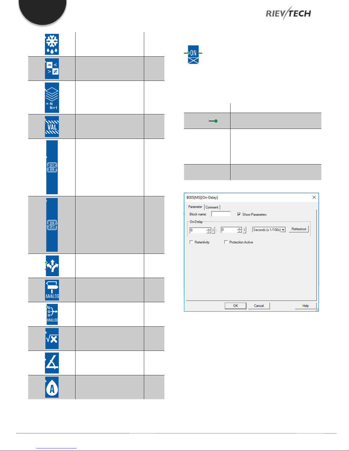
EN
On-Delay
Defrost
Comparison of 2 values
Multicompare
Compare in Zone
Convert Word to Bits
Convert Bits to Word
Description of function
The output is not switched on until a configured delay time has
expired.
Connection Description
Trg input ( )
Parameter
Output Q
The on-delay time is triggered via the
Trg (Trigger) input
T represents the on-delay time after
which the output is switched on
(output signal transition 0 to 1).
Retentivity on = the status is retentive
in memory.
Q switches on after a specified time T
has expired, provided Trg is still set.
Demultiplexer
Multiplexing
Multiplexer
Square root
Sin Cos
Absolute Humidity
Parameter T
The time for parameter T can also be pre-set based on the
actual value of another, already-configured function. You can
use the actual values of the following functions:
Analog comparator (Ax – Ay) Analog threshold trigger (Ax)
Analog amplifier (Ax) Analog multiplexer (AQ)
Analog ramp (AQ) Mathematic instruction (AQ)
PI controller (AQ) Up/down counter (Cnt)
Analog filter (AQ) Average value (AQ)
Programmable Relay ● User Manual for ELC and PR Series 48 2018 v4.5 ● © Rievtech Co., Ltd. ● www.rievtech.com

EN
s (seconds)
99:99 10 ms
± 10 ms
m (minutes)
99:59 1s
± 1 s
h (hours)
99:59 1 min
± 1 min
ms
99990
Number of ms
± 10 ms
s
5999
Number of s
± 1 s
m
5999
Number of min
± 1 min
Max/Min (AQ) On-delay (Ta)
Off-delay (Ta) On-/off-delay (Ta)
Retentive on-delay (Ta) Wiping relay(pulse output) (Ta)
Edge triggered wiping relay (Ta)
Asynchronous pulse generator (Ta)
Stairway light switch (Ta) Multiple function switch (Ta)
Stopwatch (Ta)
You select the required function via the block number. The
time-base can be adjusted.
The value of “T” can be set/modified in parameter mode. For
information about how to modify,refer to chapter 5.2.2,
please.
For information on the validity and accuracy of the time base,
refer to the xLogic time-base list as follows:
Valid ranges of the time-base, if T = parameter
Time-base Max. value Min. resolution
Accuracy
Valid ranges of the time base, if T = Actual value
of an already-programmed function
The time is reset if the status at input Trg changes to 0 again
before the time T has expired.
The output is reset to 0 when input Trg is 0.
Off-Delay
Description of function
The output with off delay is not reset until a defined time has
expired.
Connection Description
Start the off-delay time with a negative
Trg input ( )
edge (1 to 0 transition) at input Trg
(Trigger)
Reset the off-delay time and set the
Input R ( )
output to 0 via the R (Reset) input.
Reset has priority over Trg
T: The output is switched off on the
expiration of the delay time T (output
Parameter
signal transition 1 to 0).
Retentivity on = the status is retentive
in memory.
Output Q
Q is switched on for the duration of
the time T after a trigger at input Trg.
Time-base Max. value
Meaning
Accuracy
Timing diagram
The time Ta (the current time in xLogic) is triggered with the 0
to 1 transition at input Trg.
If the status at input Trg stays 1 at least for the duration of the
configured time T, the output is set to 1 when this time has
expired (the on-signal of the output follows the on-signal of the
input with delay).
Parameter
The time set in parameter T can be supplied by the value of
another already-programmed function:
Programmable Relay ● User Manual for ELC and PR Series 49 2018 v4.5 ● © Rievtech Co., Ltd. ● www.rievtech.com

EN
Analog comparator (Ax – Ay) Analog threshold trigger (Ax)
Analog amplifier (Ax) Analog multiplexer (AQ)
Analog ramp (AQ) Mathematic instruction (AQ)
PI controller (AQ) Up/down counter (Cnt)
Analog filter (AQ) Average value (AQ)
Max/Min (AQ) On-delay (Ta)
Off-delay (Ta) On-/off-delay (Ta)
Retentive on-delay (Ta) Wiping relay(pulse output) (Ta)
Edge triggered wiping relay (Ta)
Asynchronous pulse generator (Ta)
Stairway light switch (Ta) Multiple function switch (Ta)
Stopwatch (Ta)
The value of “T” is set/modified in parameter mode. For
information about how to modify, refer to chapter 5.2.2,
please.
Select the required function by the block number. The time
base is configurable.
On/Off-Delay
Description of function
The on/off delay function is used to set an output after a
configured-on delay time and then reset it again upon
expiration of a second configured time.
Connection Description
You trigger the on delay with a
Trg input ( )
positive edge (0 to 1 transition) at
input Trg (Trigger).
TH is the on-delay time for the output
(output signal transition 0 to 1).
Parameter
TL is the off-delay time for the output
(output signal transition 1 to 0).
Retentivity on = the status is retentive
in memory.
Q is switched on upon expiration of a
configured time TH if Trg is still set. It
Output Q
is switched off again upon expiration
of the time TL and if Trg has not been
set again.
For information on valid time base ranges and parameter preset, refer to chapter 4.4.1 the On-delay topic.
Timing diagram
Output Q is set to 1 momentarily with a 0 to 1 transition at
input Trg. At the 1 to 0 transition at input Trg, xLogic retriggers
the current time T, and the output remains set. The output Q
is reset to 0 when Ta reaches the value specified in T (Ta=T) (off
delay).
A one-shot at input Trg retriggers the time Ta.
You can reset the time Ta and the output via the input R (Reset)
before the time Ta has expired.
If retentivity is not set, output Q and the expired time are reset
after a power failure.
Parameter
The on-delay time and off-delay time set in parameter TH and
TL can be provided by the actual value of another alreadyprogrammed function:
Analog comparator (Ax – Ay) Analog threshold trigger (Ax)
Programmable Relay ● User Manual for ELC and PR Series 50 2018 v4.5 ● © Rievtech Co., Ltd. ● www.rievtech.com
Analog amplifier (Ax) Analog multiplexer (AQ)

EN
Analog ramp (AQ) Mathematic instruction (AQ)
PI controller (AQ) Up/down counter (Cnt)
Analog filter (AQ) Average value (AQ)
Max/Min (AQ) On-delay (Ta)
Off-delay (Ta) On-/off-delay (Ta)
Retentive on-delay (Ta) Wiping relay(pulse output) (Ta)
Edge triggered wiping relay (Ta)
Asynchronous pulse generator (Ta)
Stairway light switch (Ta) Multiple function switch (Ta)
Stopwatch (Ta)
The value of “TH” and “TL” is set/modified in parameter mode.
For information about how to modify, refer to chapter 7.2.2,
please.
For information on the validity and accuracy of the time base,
refer to 7.4.2
Timing diagram
Retentive On-Delay
Description of function
A one-shot at the input triggers a configurable time. The
output is set upon expiration of this time.
Connection Description
Trg input ( )
Trigger the on-delay time via the Trg
(Trigger) input.
Reset the time on delay time and
Input R ( )
reset the output to 0 via input R
(Reset).
The reset takes priority over Trg.
T is the on-delay time for the output
Parameter
Output Q
(output signal transition 0 to 1).
Retentivity on = the status is retentive
in memory.
Q is switched on upon expiration of
the time T.
The time TH is triggered with a 0 to 1 transition at input Trg.
If the status at input Trg is 1 at least for the duration of the
configured time TH, the output is set to logical 1 upon
expiration of this time (output is on delayed to the input signal).
The time TH is reset if the status at input Trg is reset to 0 before
this time has expired.
Parameter
The time TL is triggered with the 1 to 0 transition at the output.
The time in parameter T can be provided by the value of
If the status at input Trg remains 0 at least for the duration of
another already-programmed function:
a configured time TL, the output is reset to 0 upon expiration
of this time (output is off delayed to the input signal).
The time TL is reset if the status at input Trg returns to 1 before
this time has expired.
Analog comparator (Ax – Ay) Analog threshold trigger (Ax)
Analog amplifier (Ax) Analog multiplexer (AQ)
Analog ramp (AQ) Mathematic instruction (AQ)
PI controller (AQ) Up/down counter (Cnt)
Programmable Relay ● User Manual for ELC and PR Series 51 2018 v4.5 ● © Rievtech Co., Ltd. ● www.rievtech.com

EN
Retentivity set (on) = the status is
Analog filter (AQ) Average value (AQ)
Max/Min (AQ) On-delay (Ta)
Off-delay (Ta) On-/off-delay (Ta)
Retentive on-delay (Ta) Wiping relay(pulse output) (Ta)
Edge triggered wiping relay (Ta)
Asynchronous pulse generator (Ta)
Stairway light switch (Ta) Multiple function switch (Ta)
Output Q
retentive in memory.
A pulse at Trg sets Q. The output
stays set until the time T has expired
and if Trg = 1 for the duration of this
time. A 1 to 0 transition at Trg prior to
the expiration of T also resets the
output to 0.
Stopwatch (Ta)
The value of “T” can be set/modified in parameter mode. For
information about how to modify, refer to chapter 5.2.2,
please.
Timing diagram
The current time Ta is triggered with a 0 to 1 signal transition
at input Trg. Output Q is set to 1 when Ta reaches the time T.
A further pulse at input Trg does not affect Ta.
The output and the time Ta are only reset to 0 with a ‘1’ signal
at input R.
If retentivity is not set, output Q and the expired time are reset
after a power failure.
Wiping Relay (pulse output)
Parameter
The off-time T can be provided by the actual value of another
already-programmed function:
Analog comparator (Ax – Ay) Analog threshold
trigger (Ax)
Analog amplifier (Ax) Analog multiplexer
(AQ)
Analog ramp (AQ) Mathematic
instruction (AQ)
PI controller (AQ) Up/down counter
Description of function
An input signal generates an output signal of a configurable
length.
Connection Description
Trg input ( )
You trigger the time for the wiping
relay with a signal at input Trg (Trigger)
(Cnt)
Analog filter (AQ) Average value (AQ)
Max/Min (AQ) On-delay (Ta)
Off-delay (Ta) On-/off-delay (Ta)
Retentive on-delay (Ta) Wiping relay(pulse
output) (Ta)
Edge triggered wiping relay (Ta)
TL represents the time after which the
Parameter
output is reset (output signal transition
Asynchronous pulse generator (Ta)
1 to 0).
Programmable Relay ● User Manual for ELC and PR Series 52 2018 v4.5 ● © Rievtech Co., Ltd. ● www.rievtech.com

EN
Stairway light switch (Ta) Multiple function
switch (Ta)
Stopwatch (Ta)
The value of “TL” can be set/modified in parameter mode. For
information about how to modify, refer to chapter 5.2.2,
please.
Timing diagram
With the input signal Trg = 1, output Q is set to 1. The signal
also triggers the time Ta, while the output remains set.
When Ta reaches the value defined at T (Ta=T), the output Q
is reset to 0 state (pulse output).
If the signal at input Trg changes from 1 to 0 before this time
has expired, the output is immediately reset from 1 to 0.
Output Q is set when the time TL has
Output Q
expired and is reset when TH has
expired.
Parameter
The pulse width TH and the inter-pulse width TL can be
provided by the actual value of another already-programmed
function:
Edge Triggered Wiping Relay
Description of function
An input pulse generates a pre-set number of output pulses
with a defined pulse/pause ratio (retriggerable) after a
configured delay time has expired.
Connection Description
You trigger the times for the Edge-
Trg input ( )
triggered wiping relay with a signal at
input Trg (Trigger).
Input R ( )
The output and the current time Ta are
reset to 0 with a signal at input R.
TL, TH: The inter-pulse period TL and
the pulse period TH are adjustable.
N determines the number of
Parameter
pulse/pause cycles TL / TH:
Value range: 1...9.
Retentivity set (on) = the status is
retentive in memory
Analog comparator (Ax – Ay) Analog threshold trigger (Ax)
Analog amplifier (Ax) Analog multiplexer (AQ)
Analog ramp (AQ) Mathematic instruction (AQ)
PI controller (AQ) Up/down counter (Cnt)
Analog filter (AQ) Average value (AQ)
Max/Min (AQ) On-delay (Ta)
Off-delay (Ta) On-/off-delay (Ta)
Retentive on-delay (Ta) Wiping relay(pulse output) (Ta)
Edge triggered wiping relay (Ta)
Asynchronous pulse generator (Ta)
Stairway light switch (Ta) Multiple function switch (Ta)
Stopwatch (Ta)
The value of “TH” and ”TL” can be set/modified in parameter
mode. For information about how to modify, refer to chapter
5.2.2, please.
Programmable Relay ● User Manual for ELC and PR Series 53 2018 v4.5 ● © Rievtech Co., Ltd. ● www.rievtech.com

EN
Timing diagram
TL = 0; N = 1
With the change at input Trg to 1, the time TL (time low) is
triggered. After the time TL has expired, output Q is set to 1 for
the duration of the time TH (time high).
If input Trg is retriggered prior to the expiration of the preset
time (TL + TH), the time Ta is reset, and the pulse/pause period
is restarted.
If retentivity is not set, output Q and the time are reset after a
power failure.
Parameter
Asynchronous Pulse Generator
Description of function
The pulse shape at the output can be modified via
a configurable pulse/pause ratio.
Connection Description
You enable/disable the asynchronous
Input En ( )
pulse generator with the signal at
input En.
The Inv input can be used to invert the
Input Inv
output signal of the active
asynchronous pulse generator.
TL, TH: You can customize the pulse
Parameter
(TL)/ pause (TH) ratio.
Retentivity set (on) = the status is
retentive in memory.
Output Q
Q is toggled on and off cyclically with
the pulse times TH and TL.
The pulse width TH and the inter-pulse width TL can be
provided by the actual value of another already-programmed
function:
Analog comparator (Ax – Ay) Analog threshold trigger (Ax)
Analog amplifier (Ax) Analog multiplexer (AQ)
Analog ramp (AQ) Mathematic instruction (AQ)
PI controller (AQ) Up/down counter (Cnt)
Analog filter (AQ) Average value (AQ)
Max/Min (AQ) On-delay (Ta)
Off-delay (Ta) On-/off-delay (Ta)
Retentive on-delay (Ta) Wiping relay(pulse output) (Ta)
Edge triggered wiping relay (Ta)
Asynchronous pulse generator (Ta)
Stairway light switch (Ta) Multiple function switch (Ta)
Stopwatch (Ta)
The value of “TH” and “TL” can be set/modified in parameter
mode. For information about how to modify, please refer to
chapter 5.2.2.
Programmable Relay ● User Manual for ELC and PR Series 54 2018 v4.5 ● © Rievtech Co., Ltd. ● www.rievtech.com

Timing diagram
You can set the pulse/pause ratio at the TH (Time High) and TL
(Time Low) parameters.
The INV input can be used to invert the output signal. The input
block INV only inverts the output signal if the block is enabled
via EN.
If retentivity is not set, output Q and the expired time are reset
after a power failure.
EN
Random Generator
Description of function
The output of a random generator is toggled within a
configurable time.
Connection Description
The positive edge (0 to 1 transition) at
the enable input En (Enable) triggers
Input En ( )
the on delay for the random generator.
The negative edge (1 to 0 transition)
triggers the off delay for the random
generator.
TH: The on delay is determined at
Parameter
random and lies between 0 s and TH.
TL: The off delay is determined at
random and lies between 0 s and TL.
Q is set on, expiration of the on delay
Output Q
if En is still set. It is reset when the offdelay timer has expired and if En has
not been set again.
Parameter
The on-delay time TH and the off-delay time TL can be provided
by the actual value of another already-programmed function:
Analog comparator (Ax – Ay) Analog threshold trigger (Ax)
Analog amplifier (Ax) Analog multiplexer (AQ)
Analog ramp (AQ) Mathematic instruction (AQ)
PI controller (AQ) Up/down counter (Cnt)
Analog filter (AQ) Average value (AQ)
Max/Min (AQ) On-delay (Ta)
Off-delay (Ta) On-/off-delay (Ta)
Retentive on-delay (Ta) Wiping relay(pulse output) (Ta)
Edge triggered wiping relay (Ta)
Asynchronous pulse generator (Ta)
Stairway light switch (Ta) Multiple function switch (Ta)
Stopwatch (Ta)
The value of “TH” and “TL” can be set/modified in parameter
mode. For information about how to modify, refer to chapter
5.2.2, please.
Programmable Relay ● User Manual for ELC and PR Series 55 2018 v4.5 ● © Rievtech Co., Ltd. ● www.rievtech.com

EN
Timing diagram
With the 0 to 1 transition at input En, a random time (on delay
time) between 0 s and TH is set and triggered. If the status at
input En is 1 at least for the duration of the On delay, the output
is set to 1 when this On delay time has expired.
The time is reset if the status at input En is reset to 0 before
the On-delay time has expired.
When input En is reset 0, a random time (off delay time)
between 0 s and TL is set and triggered.
If the status at input En is 0 at least for the duration of the offdelay time, the output Q is reset to 0 when the off-delay time
has expired.
Output Q
Q is reset after the time T has expired.
A warning signal can be output before
this time has expired.
The time is reset if the status at input En returns to 1 before
the on-delay time has expired.
Stairway Lighting Switch
Description of function
The edge of an input pulse triggers a configurable time. The
output is reset when this time has expired. An off warning can
be output prior to the expiration of this time.
Connection Description
You trigger the time (off delay) for the
Trg input ( )
stairway switch with a signal at input
Trg (Trigger).
T: The output is reset (1 to 0 transition
when the time T has expired.
T!: Determines the triggering time for
Parameter
the pre-warning.
T!L: Determines the length of the pre-
warning time.
Retentivity set (on) = the status is
retentive in memory.
Parameter
The off-delay time T, the pre-warning time T! and the prewarning period T!L can be provided by the actual value of
another already-programmed function:
Analog comparator (Ax – Ay) Analog threshold trigger (Ax)
Analog amplifier (Ax) Analog multiplexer (AQ)
Analog ramp (AQ) Mathematic instruction (AQ)
PI controller (AQ) Up/down counter (Cnt)
Analog filter (AQ) Average value (AQ)
Max/Min (AQ) On-delay (Ta)
Off-delay (Ta) On-/off-delay (Ta)
Retentive on-delay (Ta) Wiping relay(pulse output) (Ta)
Edge triggered wiping relay (Ta)
Asynchronous pulse generator (Ta)
Stairway light switch (Ta) Multiple function switch (Ta)
Stopwatch (Ta)
Programmable Relay ● User Manual for ELC and PR Series 56 2018 v4.5 ● © Rievtech Co., Ltd. ● www.rievtech.com

EN
The value of “T” can be set/modified in parameter mode. For
information about how to modify, refer to chapter 5.2.2,
please.
Timing diagram
Changing the time base
You can change the pre-warning time base and the period.
Time base T
Pre-warning time
Seconds 750 ms
Minutes 15 s
Hours 15 min
Pre-warning period
50 ms
1 s
1 min
* makes sense only for programs with a cycle time of < 25
ms
Output Q is set to 1 with a 0 to 1 signal transition at input Trg.
The 1 to 0 transition at input Trg triggers the current time and
output Q remains set.
Output Q is reset to 0 when Ta reaches the time T. Before the
off-delay time (T - T!) has expired, you can output a prewarning that resets Q for the duration of the off pre-warning
time T!L.
Ta is retriggered (optional) at the next high/low transition at
input Trg and if Ta is expiring.
If retentivity is not set, output Q and the expired time are reset
after a power failure.
Multiple Function Switch
Description of function
Switched with two different functions:
1. Pulse switch with off delay
2. Switch (continuous light)
Connection Description
With a signal at input Trg (Trigger), you
Trg input ( )
set output Q (continuous light), or
reset Q with off delay. Output Q can
be reset with a signal at the Trg input.
You set the current time Ta, and reset
Input R ( )
the output to 0, with a signal at input
R.
T: The output is reset (1 to 0
transition) when the time T has
expired.
TL: Determines the period during
which the input must be set in order
to enable the permanent light
Parameter
function.
T!: Determines the on delay for the
pre-warning time.
T!L: Determines the length of the pre-
warning time.
Retentivity set (on) = the status is
retentive in memory.
Output Q is set with a signal at input
Trg, and it is reset again after a
Output Q
configured time has expired and
depending on the pulse width at input
Trg, or it is reset with another signal at
input Trg.
Setting the Par parameter
NOTICE:
All times must have the same time base.
View in parameter assignment mode (example):
Programmable Relay ● User Manual for ELC and PR Series 57 2018 v4.5 ● © Rievtech Co., Ltd. ● www.rievtech.com
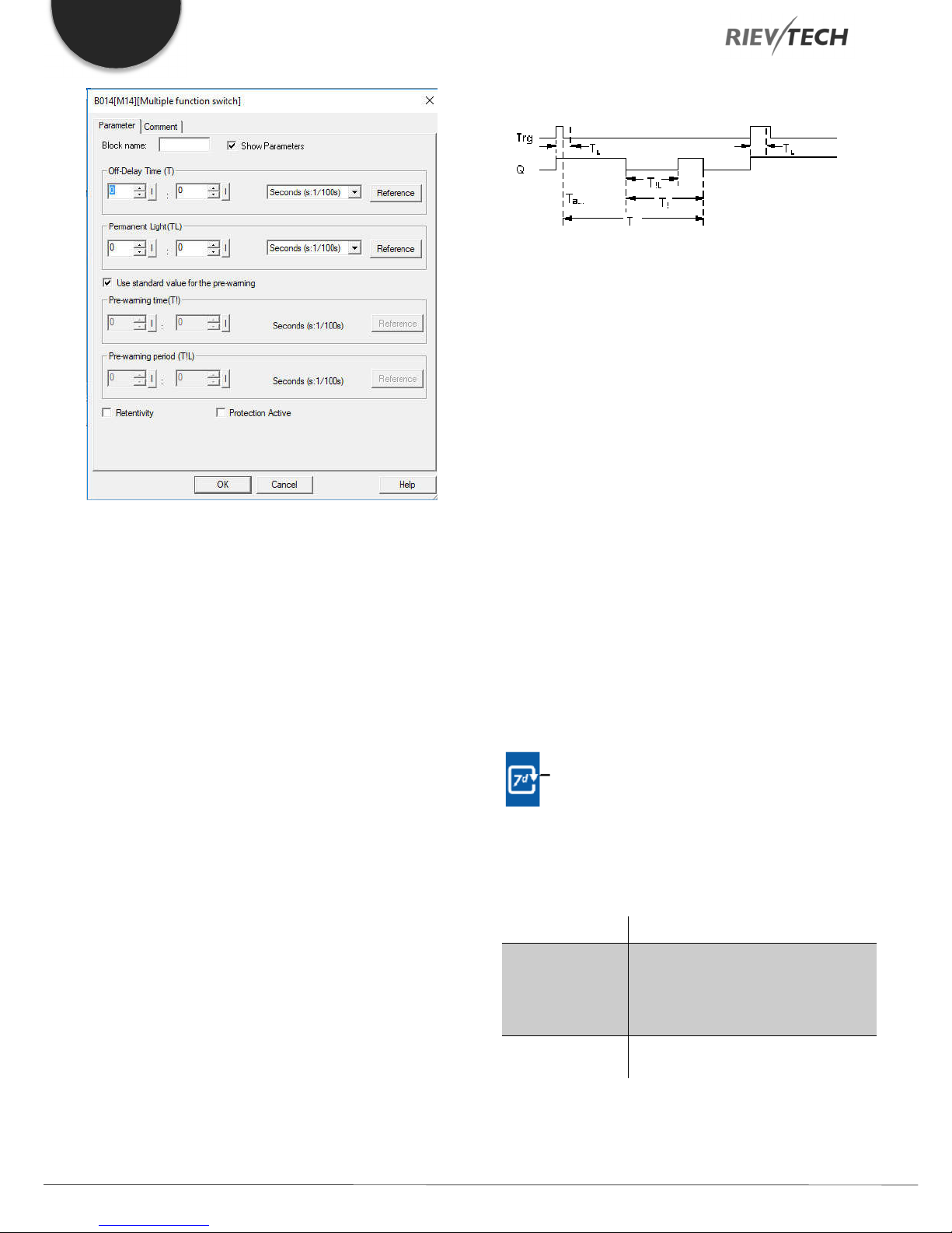
EN
Timing diagram
Parameter
The off-delay time T, the permanent light time TL, the on-delay
pre-warning time T!, and the pre-warning time period T!L can
be provided by the actual value of another alreadyprogrammed function:
Analog comparator (Ax – Ay) Analog threshold trigger (Ax)
Analog amplifier (Ax) Analog multiplexer (AQ)
Output Q is set to 1 with a 0 to 1 signal transition at Trg.
If output Q = 0, and input Trg is set hi at least for the duration
of TL, the permanent lighting function is enabled, and output
Q is set accordingly.
The off delay time T is triggered when the status at input Trg
changes to 0 before the time TL has expired.
Output Q is reset when the Ta = T.
Before the off delay time (T - T!) has expired, you can output
an off pre-warning that resets Q for the duration of the off prewarning time T!L.
A further signal at input Trg always resets T and output Q.
Caution
The time base for the T, T! and T!L must be identical.
If retentivity is not set, output Q and the expired time are reset
after a power failure.
Analog ramp (AQ) Mathematic instruction (AQ)
PI controller (AQ) Up/down counter (Cnt)
Analog filter (AQ) Average value (AQ)
Max/Min (AQ) On-delay (Ta)
Off-delay (Ta) On-/off-delay (Ta)
Retentive on-delay (Ta) Wiping relay(pulse output) (Ta)
Edge triggered wiping relay (Ta)
Asynchronous pulse generator (Ta)
Stairway light switch (Ta) Multiple function switch (Ta)
Stopwatch (Ta)
The value of “TL”, ”T”can be set/modified in parameter mode.
For information about how to modify, refer to chapter 5.2.2,
please.
Weekly Timer
Description of function
The output is controlled by means of a configurable on/off
date. The function supports any combination of weekdays.
Connection Description
At the No1, No2, No3 (cam)
parameters you set the on and off
Parameter
triggers for each cam of the weekly
timer. The parameter units are the
days and the time-of-day.
Output Q
Q is set when the configured cam is
actuated.
Programmable Relay ● User Manual for ELC and PR Series 58 2018 v4.5 ● © Rievtech Co., Ltd. ● www.rievtech.com
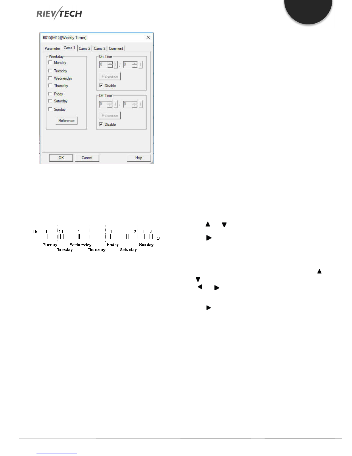
EN
Parameter
You can configure a time hysteresis for each individual cam in
parameter mode. For information about how to modify, refer
to chapter 4.2.2, please.
Timing diagram (three practical examples)
● M: Monday
● T: Tuesday
● W: Wednesday
● T: Thursday
● F: Friday
On-/Off-times
Any time between 00:00h and 23:59h is possible. You can
also configure the on time to be a pulse signal. The timer block
will be activated at the specified time for one cycle and then
the output is reset.
- -:- - means: No on/off-times set.
Setting the weekly timer
To set the on-/off-times:
1. Move the cursor to one of the Cam parameters of the timer
(e.g. No1).
2. Press OK. xLogic opens the Cam parameter assignment
screen form. The cursor is positioned on the day of the week.
No1: Daily: 06:30 h to 08:00 h
No2: Tuesday: 03:10 h to 04:15 h
No3: Saturday and Sunday: 16:30 h to 23:10 h
Description of the function
Each weekly timer is equipped with three cams. You can
configure a time hysteresis for each individual cam. For the
cams, you set the on and off hysteresis. The weekly timer sets
the output at a certain time, provided it is not already set.
The output is reset at a certain time, provided it is not already
reset. A conflict is generated in the weekly timer when the set
on time and the set off time at another cam are identical. In
this case, cam 3 takes priority over cam 2, while cam 2 takes
priority over cam 1.
The switching status of the weekly timer is determined by the
status at the No1, No2 and No3 cams.
Days of the week
The prefix "D=" (Day) has the following meaning:
3. Press and to select one or several days of the week.
4. Press to move the cursor to the first position of the ontime.
5. Set the on-time.
Modify the value at the respective position, using the keys
and . Move to the cursor to the various positions, using the
keys and . At the first position, you can only select the
value - -:- - (- -:- - means: No on/off-times set).
6. Press to move the cursor to the first position of the offtime.
7. Set the off-time (in the same way as in step 5).
8. Confirm your entries with OK.
The cursor is now positioned on the No2 parameter (Cam2)
and you can configure a further cam.
Special characteristics to note when configuring
The block properties window offers a tab for each one of the
three cams. Here you can set the weekly on times for the
cams. Each tab offers you, in addition, an option of defining
the on and off times for each cam in hour and minute units.
Hence, the shortest switching cycle is one minute.
Programmable Relay ● User Manual for ELC and PR Series 59 2018 v4.5 ● © Rievtech Co., Ltd. ● www.rievtech.com

EN
You can disable the on and off times individually, i.e. you can
achieve switching cycles extending across more than one day,
for example, by setting the on time for cam 1 to Monday 7:00h
and the off time of cam 2 to Wednesday 13:07h, while
disabling the on time for cam 2.
Backup of the real-time clock
The internal real-time clock of xLogic is buffered against power
failure. The buffering time is influenced by the ambient
temperature and is typically 100 hours at an ambient
temperature of 25°C.
In order to set the weekly timer parameters via MODBUS,
they can be assigned to an Analogue flag, AF, which would
hold a value to represent the bits for each day of the week.
Weekday parameter.
For example, use AF1
AF has a 16-bit type value, the weekday uses the low 8-bits
status as the parameters:
Bit 7 Bit 6 Bit 5 Bit 4 Bit 3 Bit 2 Bit 1 Bit 0
0
(Reserved)
SAT FRI THU WED TUE MON SUN
You can program as above, use one Bit to word block and
then, you can set the F1--F7 at the touch screen to change
the weekday settings.
On time/Off Time settings--Reference AF value.
For example,
If AF2 =800, then the On time would be 08:00;
If AF2=2105, then the On time would be 21:05;
If AF3=1023, then the OFF time would be 10:23;
Programmable Relay ● User Manual for ELC and PR Series 60 2018 v4.5 ● © Rievtech Co., Ltd. ● www.rievtech.com

EN
NOTICE:
If the AF value is over 2323, it will be not available for
the On/Off time, the output of the weekly timer will be 0.
Yearly Timer
Description of function
The output is controlled by means of a configurable on/off date
Connection Description
At the No (cam) parameter you set the
Parameter
on and off trigger for the cam of the
yearly timer.
Output Q
Q is set on when the configured cam
is switched on.
Timing diagrams
Example 1: Yearly mode on, Monthly mode off, Pulse Off, On
Time = 2000-06-01, Off Time = 2099-08-31: Every year on
June 1 the timer output switches on and remains on until
August 31.
Example 2: Yearly mode on, Monthly mode off, Pulse on, On
Time = 2000-03-15, Off Time = 2099-**-**: Every year on
March 15, the timer switches on for one cycle.
Parameter
The on and off trigger for the cam of the yearly timer can be
set/modified in parameter mode and you can configure what
you need. For information about how to modify, please refer to
chapter 5.2.2.
Example 3: Yearly mode on, Monthly mode off, Pulse off, On
Time = 2008-06-01, Off Time = 2010-08-31: On June 1 of
2008, 2009, and 2010 the timer output switches on and
remains on until August 31.
Example 4: Yearly mode on, Monthly mode off, Pulse on, On
Time = 2008-03-15, Off Time = 2010-**-**: On March 15 of
2008, 2009, and 2010, the timer output switches on for one
cycle.
Programmable Relay ● User Manual for ELC and PR Series 61 2018 v4.5 ● © Rievtech Co., Ltd. ● www.rievtech.com
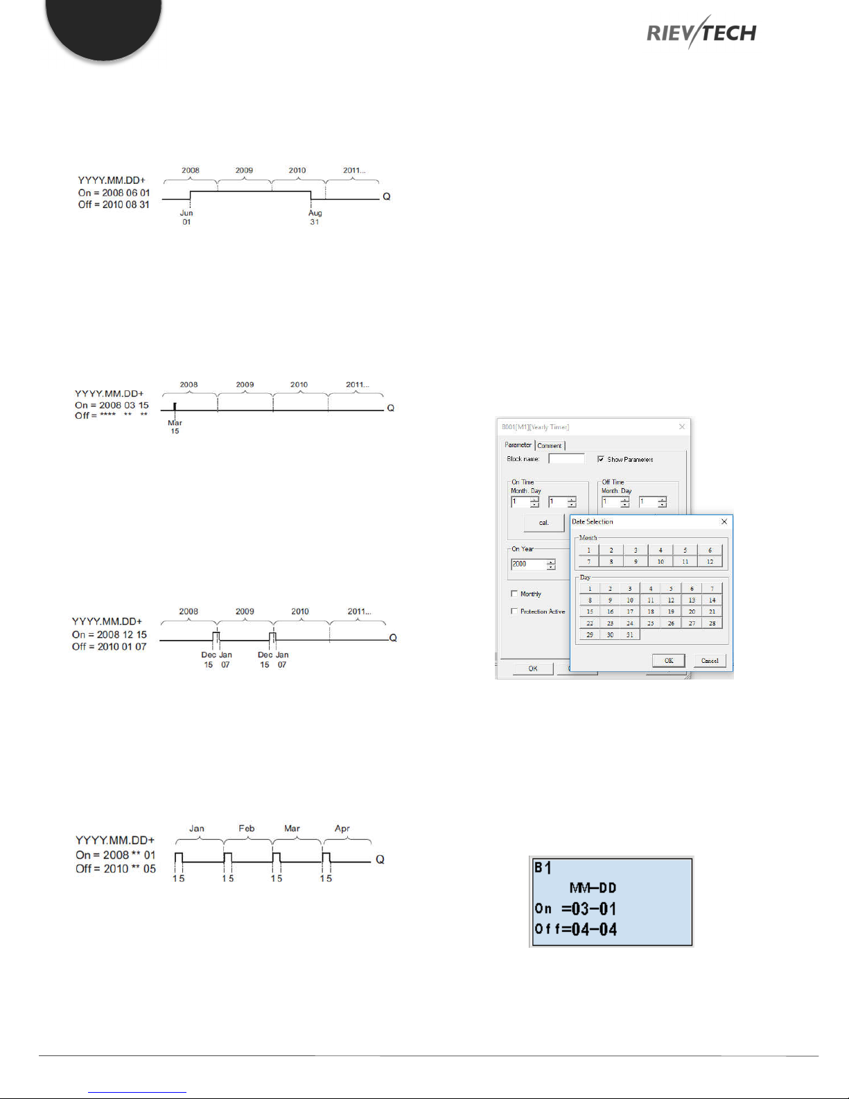
EN
Example 5: Yearly mode off, Monthly mode off, Pulse off, On
Time = 2008-06-01, Off Time = 2008-08-31: On June 1,
2008, the timer output switches on and remains on until
August 31, 2010.
Example 6: Yearly mode off, Monthly mode off, Pulse selected,
On Time = 2008-03-15, Off Time = ****-**-**: On March 15,
2008, the timer output switches on for one cycle. Because the
timer does not have a monthly or yearly action, the timer
output pulses only one time at the specified On Time.
When you select the every month check box, the yearly clock
switches on or off at a certain day of every month.
Backup of the real-time clock
The internal real-time clock of xLogic is buffered against power
failure. The buffering time is influenced by the ambient
temperature and is typically 100 hours at an ambient
temperature of 25°C.
Special characteristics to note when configuring
A click on the dialogue box enables direct keyboard input of
the month and day values. The values entered may not exceed
the logical maximum of the relevant input boxes; otherwise
xLogicsoft returns an error message.
The calendar icon offers you a Rievtech way of setting the
date. It opens a window where you can set the days and
months by clicking the relevant buttons.
Example 7: Yearly mode on, Monthly mode off, Pulse off, On
Time = 2008-12-15, Off Time = 2010-01-07: On December
15 of 2008 and 2009, the timer output switches on and
remains on until January 7 of the following year. When the
timer output turns off on January 7, 2010, it does NOT turn on
again the following December 15.
Example 8: Yearly mode on, Monthly mode on, On Time =
2008-**-01, Off Time = 2010-**-05: Starting in 2008, on the
first day of each month the timer output switches on and
switches off on the fifth day of the month. The timer continues
in this pattern through the last month of 2010.
Sample configuration
The output of an xLogic is to be set annually on March 1, reset
on April 4, set again on July 7, and reset again on November
19. You need to configure two yearly timers with
corresponding on-times. Then logically link the outputs by
means of an OR block.
Description of the function
The yearly timer sets and resets the output at specific on and
off times. The off-date identifies the day on which the output
is reset again. The first value defines the month, the second
the day.
Programmable Relay ● User Manual for ELC and PR Series 62 2018 v4.5 ● © Rievtech Co., Ltd. ● www.rievtech.com
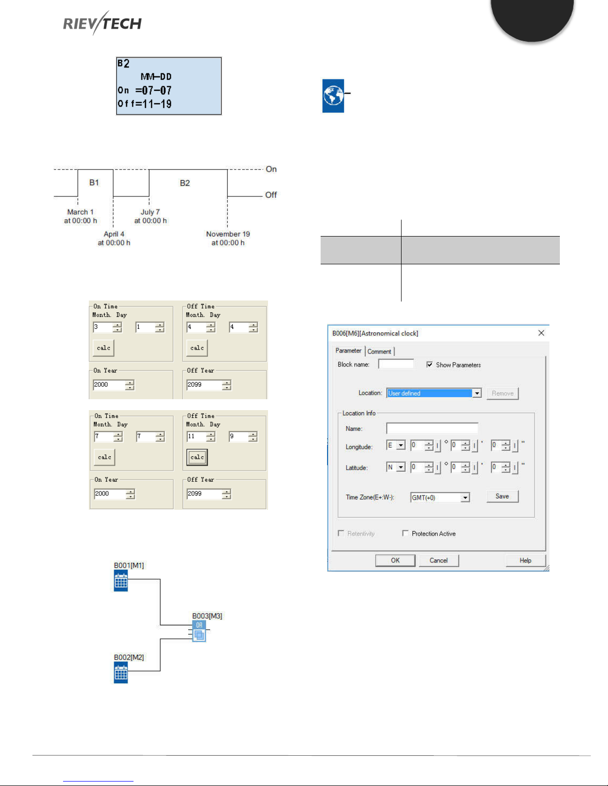
Astronomical Clock
EN
Result
Place two yearly timer switch SFBs on your programming
interface and configure the blocks as specified.
Description of function
The astronomical clock SFB is used to set an output high
between sunrise and sunset based on the local time at the
geographical location of the xLogic device. The output status
of this function block also depends on the configuration of
Summertime/Winter time or Daylight Savings settings.
Connection Description
Parameter
The location info including longitude,
latitude and time zone.
Q is set to Hi when the sunrise time is
Output Q
reached. It holds this state until sunset
time is reached.
Create a logical link of the blocks via a standard OR block. The
OR output is 1 if at least one of the yearly timer switches is set.
Parameters
In the astronomical clock dialogue, you can select the location
of the xLogic device. You can select one of the following predefined time zone locations:
Beijing Berlin London Rome Moscow Tokyo
Washington Ankara Madrid Amsterdam
If you select one of these locations, xLogicsoft uses the
latitude, longitude, and time zone of your selection.
Programmable Relay ● User Manual for ELC and PR Series 63 2018 v4.5 ● © Rievtech Co., Ltd. ● www.rievtech.com

EN
Alternatively, you can configure a specific latitude, longitude,
and time zone for your location, and provide a name for this
custom location.
Based on the location and time zone, xLogic calculates the
absolute sunrise and sunset time for the current day. The
block also takes Summertime/Winter Daylight Savings time
into consideration, if it is configured on the computer where
xLogicsoft is installed. To do such configuration, you should
select the checkbox of "Automatically adjust clock for daylight
for saving changes" in the "Date and Time Properties"
dialogue.
You can also set this up in the PLC using the
Transfer…..Summer Time/Winter Time menu option:
Connection Description
En (Enable) is the monitoring input.
xLogic sets the current elapsed time
Input En ( )
Input Lap
Input R ( )
Parameter
Output AQ
to 0 and begins counting elapsed time
when En transitions from 0 to 1. When
En transitions from 1 to 0, the elapsed
time is frozen.
A positive edge (0 to 1 transition) at
input Lap pauses the stopwatch and
sets the output to lap time.
A negative edge (1 to 0 transition) at
input Lap resumes the stopwatch and
set the output to current elapsed time.
A signal at input R (Reset) clears the
current elapsed time and lap time.
The time base for the elapsed time
can be set to hours, minutes,
seconds, or 1/100ths of seconds.
The output AQ outputs value of the
current elapsed time when it is a
negative edge (1 to 0 transition) at the
input Lap, and outputs value of the
Lap time when it is a positive edge (0
to 1 transition) at the input Lap.
A positive edge (0 to 1 transition)
resets the value at output AQ to 0.
Timing diagram
Description of function
The function calculates the value at the input and sets or
resets Q depending on the sunrise time and sunset time at the
configured location and time zone of the module.
Stopwatch
Description of function
Parameters Time Base
You can configure the time base for the analogue output:
The stopwatch records the time elapsed since it was enabled.
Programmable Relay ● User Manual for ELC and PR Series 64 2018 v4.5 ● © Rievtech Co., Ltd. ● www.rievtech.com

EN
The time base for the elapsed time can be in hours, minutes,
seconds, or 1/100ths of seconds (units of 10 milliseconds).
The smallest time base, and therefore the resolution, is 10
milliseconds, or 1/100ths of a second.
Timing diagram
Description of the function
When En = 1, the current time increases.
Connection Description
You reset the output and the internal
Input R ( )
counter value to zero with a signal at
input R (Reset).
This function counts the 0 to 1
Input Cnt ( )
transition at input Cnt. It does not
count 1 to 0 transitions.
Input Dir (Direction) determines the
direction of count:
Input Dir
Dir = 0: Up
Dir = 1: Down
On: On threshold
Value range: 0...99999999
Off: Off threshold
Parameter
Value range: 0...99999999
Start Val: Initial value from which to
begin counting either down or up.
Retentivity set (on) = the status is
retentive in memory.
Q is set and reset according to the
Output Q
actual value at Cnt and the set
thresholds.
When En = 0, the current time counting pauses.
When En = 1 and Lap = 0, the output AQ outputs the value of
the current elapsed time.
When En = 1 and Lap = 1, the current time continue
increasing, but the output AQ outputs the value of the Lap
time.
When En = 0 and Lap =1, the output AQ outputs the value of
the Lap time.
When En = 0 and Lap = 0, the output AQ outputs the value of
the latest current time.
When R = 1, both the current time and the Lap time are reset.
Up/Down Counter
Description of function
Parameter
The on threshold On and the off threshold Off can be provided
by the value of another already-programmed function:
Analog comparator (Ax – Ay) Analog threshold trigger (Ax)
An input pulse increments or decrements an internal value,
depending on the parameter setting. The output is set or reset
when a configured threshold is reached. The direction of count
can be changed with a signal at input Dir
Programmable Relay ● User Manual for ELC and PR Series 65 2018 v4.5 ● © Rievtech Co., Ltd. ● www.rievtech.com
Analog amplifier (Ax) Analog multiplexer (AQ)
Analog ramp (AQ) Mathematic instruction (AQ)
PI controller (AQ) Up/down counter (Cnt)
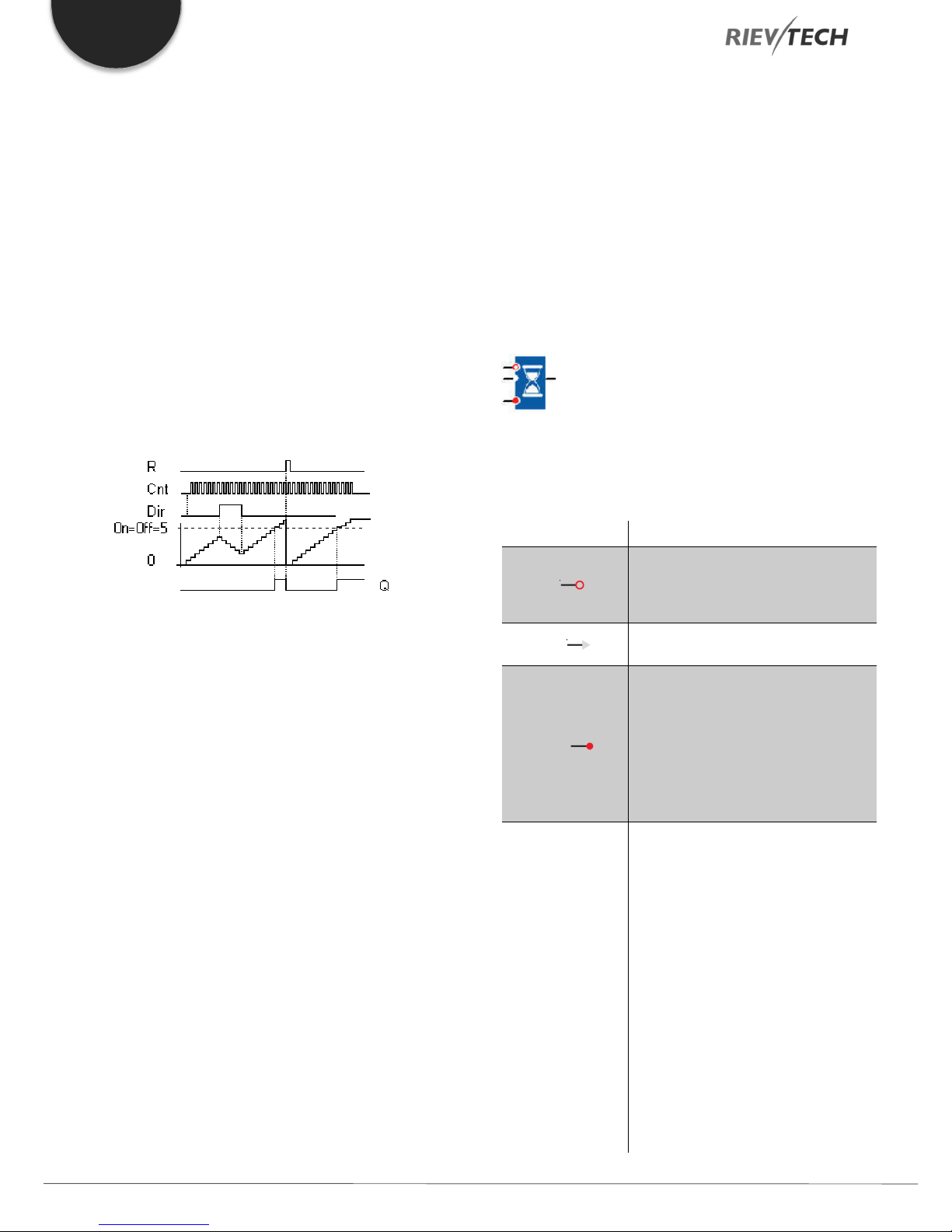
EN
Analog filter (AQ) Average value (AQ)
Max/Min (AQ) On-delay (Ta)
Off-delay (Ta) On-/off-delay (Ta)
Retentive on-delay (Ta) Wiping relay(pulse output) (Ta)
Edge triggered wiping relay (Ta)
Asynchronous pulse generator (Ta)
Stairway light switch (Ta) Multiple function switch (Ta)
Stopwatch (Ta)
The value of “On”, ”Off” and “Cnt” can be set/modified in
parameter mode.
Timing diagram
Thus, if the pulses at the fast inputs are faster than the scan
cycle time, the SFB might not switch until the specified limit
has been exceeded.
Example: Up to 100 pulses per cycle can be counted; 900
pulses have been counted so far. On = 950; Off = 10000. The
output is set in the next cycle after the value has reached
1000.
The output would not be set at all if the value Off = 980
Hours Counter
Description of function
A configured time is triggered by a signal at the monitoring
input. The output is set when this time has expired.
Connection Description
Description of the function
The function increments (Dir = 0) or decrements (Dir = 1) the
internal counter by one count with every positive edge at input
Cnt.
You can reset the internal counter value to '000000', with a
signal at the reset input R. As long as R=1, the output is 0 and
the pulses at input Cnt are not counted.
Output Q is set and reset according to the actual value at Cnt
and the set thresholds. See the following rules for calculation.
Calculation rule
If the on threshold >= off threshold, then:
Q = 1, if Cnt >= On
Q = 0, if Cnt < Off.
If the on threshold < off threshold, then:
Q = 1, if On <= Cnt < Off.
Caution
The function polls the limit value of the counter once in each
cycle.
A positive edge (0 to 1 transition) at
Input R ( )
input R resets output Q and sets a
configured value MI at the counter for
the duration of the time-to-go (MN).
Input En ( )
En is the monitoring input. xLogic
scans the on-time of this input.
A positive edge at input Ral (Reset all)
resets the hours counter (OT) and the
output, and sets the time-to-go value
(MN) to the maintenance interval MI:
Input Ral ( )
• Output Q = 0
• Measured operating time OT = 0
• Time-to-go of the maintenance
interval MN = MI.
MI: Maintenance interval to be preset
in units of hours and minutes
Range of values:
0000 h to 9999 h, 0 m to 59 m
OT: the accumulated total operating
time (you can specify an offset in
hours and minute)
Parameter
Range of values:
00000 h to 99999 h, 0 m to 59 m
Q → 0:
• When "R" is selected:
Q = 1, if MN = 0;
Q = 0, if R = 1 or Ral = 1
• When "R+En" is selected:
Programmable Relay ● User Manual for ELC and PR Series 66 2018 v4.5 ● © Rievtech Co., Ltd. ● www.rievtech.com

Q = 1, if MN = 0;
Output Q
EN
Analog comparator (Ax – Ay) Analog threshold trigger (Ax)
Q = 0, if R = 1 or Ral = 1 or En = 0.
The output is set when the time-to-go
MN = 0.
The output is reset:
• When "Q→0:R+En", if
R = 1 or Ral = 1 or En = 0
• When "Q→0:R", if R = 1 or Ral = 1.
Analog amplifier (Ax) Analog multiplexer (AQ)
Analog ramp (AQ) Mathematic instruction (AQ)
PI controller (AQ) Up/down counter (Cnt)
Analog filter (AQ) Average value (AQ)
Max/Min (AQ) On-delay (Ta)
Timing diagram
MI = Configured time interval
MN = Time-to-go
OT = Total time expired since the last 1 signal at the Ral input
These values are principally held retentive!
Off-delay (Ta) On-/off-delay (Ta)
Retentive on-delay (Ta) Wiping relay(pulse output) (Ta)
Edge triggered wiping relay (Ta)
Asynchronous pulse generator (Ta)
Stairway light switch (Ta) Multiple function switch (Ta)
Stopwatch (Ta)
The value of “MI” can be set and modified in parameter mode.
Description of the function
The hour’s counter monitors input En. As long as the status of
this input is 1, xLogic calculates the time expired and the timeto-go MN. xLogic displays these times when it is set to
configuration mode. The output is set to 1 when the time-togo is equal to zero.
You reset output Q and the time-to-go counter to the specified
value, MI with a signal at input R. The operation hour counter,
OT remains unaffected.
You reset output Q and the time-to-go counter to the specified
value MI with a signal at input Ral. The operation hour counter,
OT is reset to 0.
Depending on your configuration of the Q parameter, the
output is either reset with a reset signal at input R or Ral or
when the reset signal is 1 or the En signal is 0.
The limit value of OT
The values of the operating hours in OT are retained when you
reset the hours counter with a signal at input R. The hours
counter OT continues the count as long as En = 1, irrespective
of the status at the reset input R. The counter limit of OT is
Parameter
The maintenance interval MI can be provided by the actual
value of another already-programmed function:
99999 h. The hour’s counter stops when it reaches this value.
Parameter Pre-set
In xLogicsoft, you can define MI and an OT start value.
You can set whether or not the behaviour of Q does or does
not depend on En by selecting the corresponding checkbox.
Programmable Relay ● User Manual for ELC and PR Series 67 2018 v4.5 ● © Rievtech Co., Ltd. ● www.rievtech.com

EN
Retentivity with the hour’s counter
The hours counter in the xLogic is generally retentive.
However, if the values of the hour’s counter are lost after a
power failure, then select the respective block in your circuit
program. Right mouse click on the hours counter and select
Block Properties > Parameters. The option Retentivity must be
activated and not changeable (greyed out).
If the Retentivity option is not available, then delete the block
and insert a new special function hours counter at the same
position.
Threshold Trigger
Description of function
Parameter
The gate time G_T can be provided by the actual value of
another already-programmed function:
The output is switched on and off, depending on two
configurable frequencies.
Connection Description
The function counts 0 to 1 transitions
at input Fre.1 to 0 transitions are not
counted.
Use Inputs I5, I6 (14kHz) I7, I8 (60kHz)
Input Fre ( )
for ELC-12 CPU, Inputs I9, IA (14kHz)
IB, IC (60kHz) for PR-18, ELC-22 and
PR-24 CPU
Any other input or circuit element can
be used for low frequencies (typical 4
Hz).
On: On threshold
The range of values: 0000...9999
Off: Off threshold
Parameter
The range of values: 0000...9999
G_T: Time interval or gate time during
which the input pulses are measured.
The range of values: 00:05 s...99:99 s
Output Q
Q is set or reset according to the
threshold values.
Analog comparator (Ax – Ay) Analog threshold trigger (Ax)
Analog amplifier (Ax) Analog multiplexer (AQ)
Analog ramp (AQ) Mathematic instruction (AQ)
PI controller (AQ) Up/down counter (Cnt)
Analog filter (AQ) Average value (AQ)
Max/Min (AQ) On-delay (Ta)
Off-delay (Ta) On-/off-delay (Ta)
Retentive on-delay (Ta) Wiping relay(pulse output) (Ta)
Edge triggered wiping relay (Ta)
Asynchronous pulse generator (Ta)
Stairway light switch (Ta) Multiple function switch (Ta)
Stopwatch (Ta)
The value of “On”, ”Off” can be set/modified in parameter
mode.
Timing diagram
Programmable Relay ● User Manual for ELC and PR Series 68 2018 v4.5 ● © Rievtech Co., Ltd. ● www.rievtech.com

fa = Input frequency
Description of the function
The trigger measures the signals at input Fre. The pulses are
captured during a configurable period G_T.
Q is set or reset according to the set thresholds. See the
following calculation rule.
Calculation rule
If the threshold (On) > threshold (Off), then:
Q = 1, if fa >= On
Q = 0, if fa < Off.
If the threshold (On) < threshold (Off), then Q = 1, if
On <= fa < Off.
Analogue Comparator
EN
Description of function
The output is set and reset depending on the difference Ax Ay and on two configurable thresholds.
Connection Description
Input the analogue signals of which
you want to determine the delta at the
inputs Ax and Ay.
Input Ax, Ay
Use the analogue inputs AI1...AI8, the
analogue outputs AQ1 and AQ2.
AI1...AI8: 0 - 10 V corresponds with 0
- 1000 (internal value).
A: Gain
Range of values: ± 10.00
B: Zero offset
The range of values: ± 10,000
Parameter
On: On threshold
The range of values: ± 20,000
Off: Off threshold
The range of values: ± 20,000
p: Number of decimals
Output Q
Range of values: 0, 1, 2, 3
Q is set or reset depending on the set
thresholds.
Parameter p (number of decimals)
The on threshold On and the off threshold Off can be provided
by the actual value of another already-programmed function:
Analog comparator (Ax – Ay) Analog threshold trigger (Ax)
Analog amplifier (Ax) Analog multiplexer (AQ)
Analog ramp (AQ) Mathematic instruction (AQ)
PI controller (AQ) Up/down counter (Cnt)
Analog filter (AQ) Average value (AQ)
Max/Min (AQ) On-delay (Ta)
Off-delay (Ta) On-/off-delay (Ta)
Retentive on-delay (Ta) Wiping relay(pulse output) (Ta)
Edge triggered wiping relay (Ta)
Asynchronous pulse generator (Ta)
Stairway light switch (Ta) Multiple function switch (Ta)
Stopwatch (Ta)
Applies only to Ax, Ay, Delta, On and Off values displayed in a
message text.
Does not apply to the comparison of on and off values! (The
compare function ignores the decimal point.)
Programmable Relay ● User Manual for ELC and PR Series 69 2018 v4.5 ● © Rievtech Co., Ltd. ● www.rievtech.com

EN
See also topic "Calculating the gain and offset of analog
The value of “On”, ”Off” and ”Dec” can be set/modified in
parameter mode.
Timing diagram
Q for Ax - Ay > 200, On = Off = 200
Description of function
The function reads the value of the signal at the analogue input
Ax.
This value is multiplied by the value of parameter A (gain).
Parameter B (offset) is added to the product, hence
(Ax ∙ gain) + offset = Actual value Ax.
trigger length Trg (= output of the analogue comparator)
exceeds the defined on delay time.
This way you can set a virtual hysteresis, which renders the
input less sensitive to short changes.
Particular characteristics to be noted when configuring
For help on analogue block parameters, refer to the Analogue
value processing section in xLogicsoft.
Setting the Par parameter
The gain and offset parameters are used to adapt the sensors
to the relevant application.
Example
In a heating control system, the supply Tv and return line
temperatures Tr are to be compared, for example with a
sensor at AI2.
A control signal is to be triggered (for example "heater On")
when the difference between the supply and return line
temperatures is greater than 15 °C. The control signal is reset
when the difference is less than 5 °C.
The process variable of the temperature is to be shown in
parameter assignment mode.
(Ay ∙ gain) + offset = Actual value Ay.
Output Q is set or reset depending on the difference of the
actual values Ax - Ay and the set thresholds. See the following
calculation rule.
Calculation rule
If threshold On ≥Threshold Off, then:
1.
Q = 1, if (actual value Ax - actual value Ay) > On
Q = 0, if (actual value Ax - actual value Ay) ≤Off.
If threshold On < Threshold Off, then Q = 1, falls:
2.
On ≤ (actual value Ax - actual value Ay) < Off.
Reducing the input sensitivity of the analogue comparator
You can delay the output of the analogue comparator
selectively by means of the "on delay" and "off delay" SFBs.
By doing so, you determine that output Q is only set if the input
The thermocouples available have the following technical data:
-30 to +70 °C, 0 to 10 VDC.
Application
-30 °C to 70 °C = 0 VDC to 10
VDC
0 °C
Range of values:
-30 °C to 70 °C = 100
On threshold = 15 °C Threshold = 15
Off threshold = 5 °C Threshold = 5
Internal mapping
0 to 1000
300
→ Offset = -30
1000
→ Gain = 100/1000 = 0.1
values
Reducing the input response of the analogue comparator
You can selectively delay the output of an analogue
comparator by means of the "On-delay" and "Off-delay"
special functions. With on-delay, output Q is only set if the
pulse width of the triggering signal at input Trg (=analogue
comparator output) is longer than the on-delay time.
Programmable Relay ● User Manual for ELC and PR Series 70 2018 v4.5 ● © Rievtech Co., Ltd. ● www.rievtech.com

Using this method, you will obtain a virtual hysteresis and
reduce the input response to short signals.
Function block diagram
EN
Analogue Threshold Trigger
Description of function
The output is set or reset depending on two configurable
thresholds (hysteresis).
Connection Description
Input the analogue signal to be
evaluated at input Ax.
Input Ax
Use the analogue inputs AI1...AI8, the
analogue outputs AQ1 and AQ2.
0 - 10 V is proportional to 0 - 1000
(internal value).
A: Gain
Range of values: ± 10.00
B: Zero offset
The range of values: ± 10,000
Parameter
On: On threshold
The range of values: ±20,000
Off: Off threshold
The range of values: ± 20,000
p: Number of decimals
Range of values: 0, 1, 2, 3
Output Q
Q is set or reset depending on the set
thresholds.
Parameter On and Off
The On and Off parameters can be provided by the actual
value of another already-programmed function:
Analog comparator (Ax – Ay) Analog threshold trigger (Ax)
Analog amplifier (Ax) Analog multiplexer (AQ)
Analog ramp (AQ) Mathematic instruction (AQ)
PI controller (AQ) Up/down counter (Cnt)
Analog filter (AQ) Average value (AQ)
Max/Min (AQ) On-delay (Ta)
Off-delay (Ta) On-/off-delay (Ta)
Retentive on-delay (Ta) Wiping relay(pulse output) (Ta)
Edge triggered wiping relay (Ta)
Asynchronous pulse generator (Ta)
Stairway light switch (Ta) Multiple function switch (Ta)
Stopwatch (Ta)
Applies only to the display of On, Off and Ax values in a
message text.
Does not apply to the comparison of On and Off values! (The
compare function ignores the decimal point.)
The value of “On”, “Off” and “Dec” can be set/modified in
parameter mode.
Programmable Relay ● User Manual for ELC and PR Series 71 2018 v4.5 ● © Rievtech Co., Ltd. ● www.rievtech.com

EN
Timing diagram
Description of function
The function reads the value of the signal at the analogue input
Ax.
This value is multiplied by the value of parameter A (gain).
Parameter B (offset) is added to the product, hence
(Ax ∙Gain) + Offset = Actual value Ax.
Output Q is set or reset depending on the set threshold values.
See the following calculation rule.
Calculation rule
If threshold (On) ≥ threshold (Off), then:
Q = 1, if the actual value Ax > On
Q = 0, if the actual value Ax ≤Off.
Analogue Amplifier
Description of function
This SFB amplifies an analogue input value and returns it at
the analogue output.
Connection Description
Input Ax
Parameter
Output AQ
Input the analogue signal to be
amplified at input Ax.
Use the analogue inputs AI1...AI8, the
analogue outputs AQ1 and AQ2.
AI1...AI8: 0 - 10 V corresponds with 0
- 1000 (internal value).
A: Gain
Range of values: ± 10.00
B: Zero offset
The range of values: ± 10,000
p: Number of decimals
Range of values: 0, 1, 2, 3
Analog output
Value range for AQ: -32768...+32767
If threshold (On) < threshold (Off), then Q = 1, if
On ≤ the actual value Ax < Off.
NOTICE:
The decimal point setting must be identical in the min.
and max. range.
View in parameter assignment mode (example):
Parameter p (number of decimals)
Applies only to the display of Ax and Ay values in a message
text.
Does not apply to the comparison of On and Off values! (The
compare function ignores the decimal point.)
Programmable Relay ● User Manual for ELC and PR Series 72 2018 v4.5 ● © Rievtech Co., Ltd. ● www.rievtech.com

Description of function
The function reads the value of an analogue signal at the
analogue input Ax.
This value is multiplied by the gain parameter A. Parameter B
(offset) is added to the product, i.e.
(Ax ∙gain) + offset = Actual value Ax.
Analogue Watchdog
EN
Description of function
This special function saves the process variable of an
analogue input to memory and sets the output when the
output variable exceeds or drops below this stored value plus
a configurable offset.
Connection Description
A positive edge (0 to 1 transition) at
input En saves the analogue value at
Input En ( )
input Ax ("Aen") to memory and starts
monitoring of the analogue range Aen
± Delta.
You apply the analogue signal to be
monitored at input Ax.
Input Ax
Use the analogue inputs AI1...AI8, the
analogue outputs AQ1 and AQ2.
0 - 10 V is proportional to 0 - 1000
(internal value).
A: Gain
Range of values: ± 10.00
B: Zero offset
The range of values: ± 10,000
Delta: Difference value for the Aen
on/off threshold
The range of values: ± 20,000
Parameter
Δ1: difference value above Aen:
on/off threshold
Range of values: 0 to 20,000
Δ2: difference value below Aen:
on/off threshold
Range of values: 0 to 20,000
p: Number of decimals
Output Q
Range of values: 0, 1, 2, 3
Q is set/reset, depending on the
stored analogue value and the offset.
Parameter p (number of decimals)
The two threshold parameters Threshold 1 and Threshold 2
can be provided by the actual value of another alreadyprogrammed function:
Analog comparator (Ax – Ay) Analog threshold trigger (Ax)
Analog amplifier (Ax) Analog multiplexer (AQ)
Analog ramp (AQ) Mathematic instruction (AQ)
PI controller (AQ) Up/down counter (Cnt)
Analog filter (AQ) Average value (AQ)
Max/Min (AQ) On-delay (Ta)
Off-delay (Ta) On-/off-delay (Ta)
Retentive on-delay (Ta) Wiping relay(pulse output) (Ta)
Edge triggered wiping relay (Ta)
Asynchronous pulse generator (Ta)
Stairway light switch (Ta) Multiple function switch (Ta)
Stopwatch (Ta)
Applies only to the display of Aen, Ax and Delta values in a
message text.
Programmable Relay ● User Manual for ELC and PR Series 73 2018 v4.5 ● © Rievtech Co., Ltd. ● www.rievtech.com
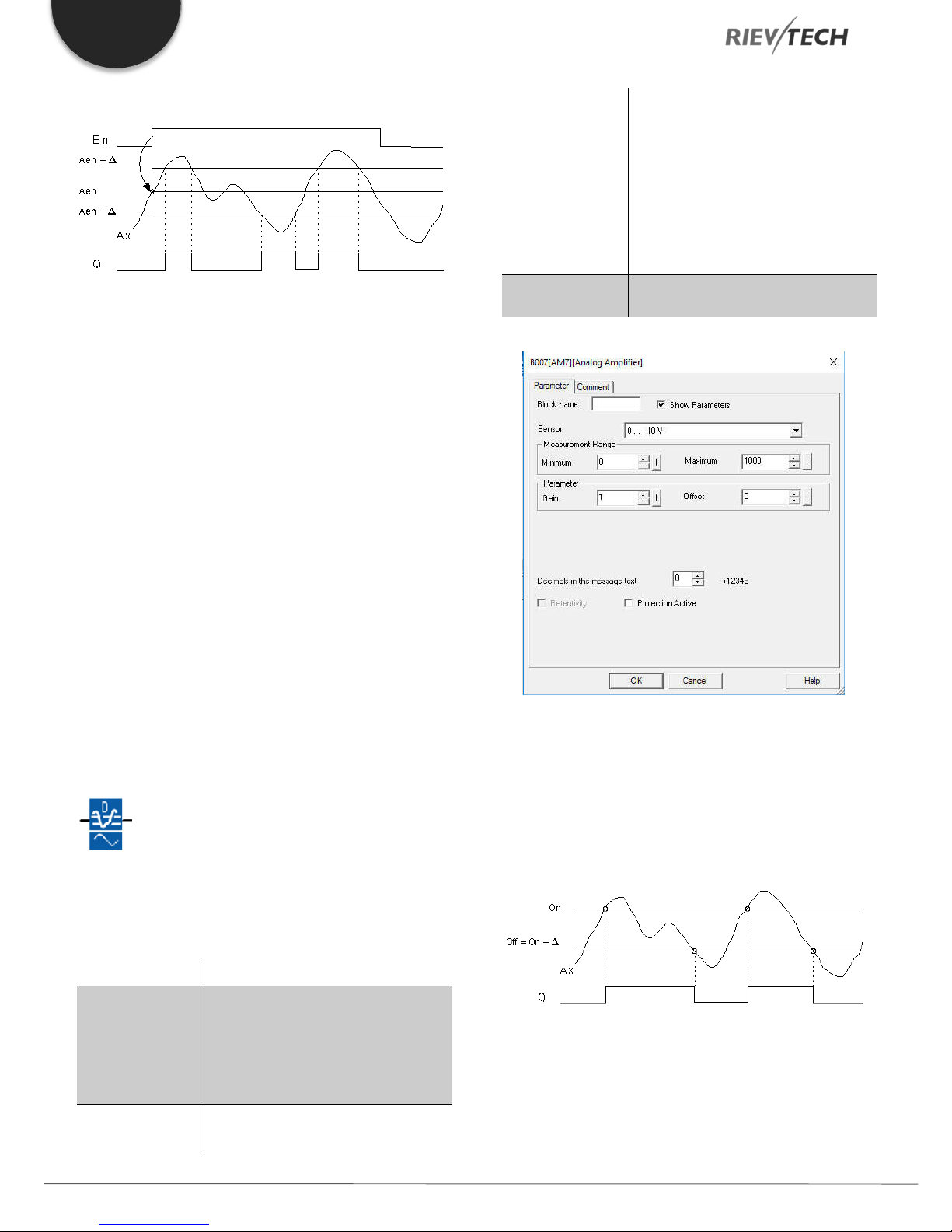
EN
B: Zero offset
Timing diagram
Description of function
A 0 to 1 transition at input En saves the value of the signal at
the analogue input Ax. This saved process variable is referred
to as “Aen”.
Both the analogue actual values Ax and Aen are multiplied by
the value of parameter A (gain), and parameter B (offset) is
then added to the product, i.e.
The range of values: ± 10,000
On: On threshold
The range of values: ±20,000
Delta: Differential value for calculating
the off parameter
The range of values: ± 20,000
p: Number of decimals
Range of values: 0, 1, 2, 3
Output Q
Q is set or reset, depending on the
threshold and difference values.
(Ax ∙ gain) + offset = Actual value Aen, when input En changes
from 0 to 1, or
(Ax ∙ gain) + offset = Actual value Ax.
Output Q is set when the signal at input En = 1 and if the actual
value of input Ax is out of range of Aen ± Delta.
Output Q is reset, when the actual value of input Ax lies within
the range of Aen +- Delta, or when the signal at input En
changes to lo.
Analogue Differential Trigger
Description of function
The output is set and reset depending on a configurable
threshold and a differential value.
Connection Description
Parameter p (number of decimals)
Applies only to the display of On, Off and Ax values in a
message text.
Does not apply to the comparison of On and Off values! (The
compare function ignores the decimal point.)
Timing diagram A: Function with a negative difference Delta
You apply the analogue signal to be
analysed at input Ax.
Input Ax
Use the analogue inputs AI1...AI8, the
analogue outputs AQ1 and AQ2.
0 - 10 V is proportional to 0 - 1000
(internal value).
Parameter
Programmable Relay ● User Manual for ELC and PR Series 74 2018 v4.5 ● © Rievtech Co., Ltd. ● www.rievtech.com
A: Gain
Range of values: ± 10.00
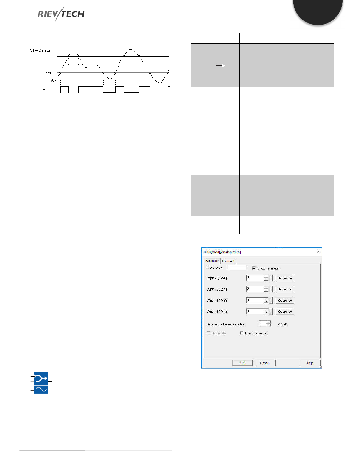
EN
Timing diagram B: Function with positive difference Delta
Description of the function
The function fetches the analogue signal at input Ax.
Ax is multiplied by the value of the A (gain) parameter, and
parameter B (offset) is added to the product, i.e.
(Ax ∙ gain) + offset = actual value of Ax.
Output Q is set or reset, depending on the set (On) threshold
and difference value (Delta). The function automatically
calculates the Off parameter: Off = On + Delta, whereby Delta
may be positive or negative. See the calculation rule below.
Calculation rule
When you set a negative differential value Delta and the On
threshold >= Off threshold, then:
Connection Description
1 on input En (Enable) switches,
dependent on S1 and S2, a
Input En ( )
Input S1 and S2
Parameter
Output AQ
parameterized analogue value to the
output AQ.
0 on input EN switches 0 to the output
AQ.
S1 and S2 (selectors) for selecting the
analogue value to be issued.
S1 = 0 and S2 = 0: The value 1 is
issued
S1 = 0 and S2 = 1: The value 2 is
issued
S1 = 0 and S2 = 1: The value 2 is
issued
S1 = 1 and S2 = 0: The value 3 is
issued
S1 = 1 and S2 = 1: The value 4 is
issued
V1...V4: Analog values (Value) that will
be issued.
Value range: -32768...+32767
p: Number of decimal places
value range: 0, 1, 2, 3
Analog output
Value range for AQ: -32768...+32767
Q = 1, if the actual value Ax > On
Q = 0, if the actual value Ax ≤ Off.
See the timing diagram A.
When you set a positive differential value Delta and the On
threshold < the Off threshold, then
Q = 1, if:
On threshold, ≤ the actual value Ax < Off threshold.
See the timing diagram B.
Analogue Multiplexer
Description of function
This special function displays 0 or one of 4 saved analogue
values on the analogue output.
Parameters V1…V4
The values for V1…V4 can be provided by the value of another
already-programmed function such as:
Analog comparator (Ax – Ay) Analog threshold trigger (Ax)
Analog amplifier (Ax) Analog multiplexer (AQ)
Programmable Relay ● User Manual for ELC and PR Series 75 2018 v4.5 ● © Rievtech Co., Ltd. ● www.rievtech.com

EN
Analog ramp (AQ) Mathematic instruction (AQ)
PI controller (AQ) Up/down counter (Cnt)
Analog filter (AQ) Average value (AQ)
Max/Min (AQ) On-delay (Ta)
Off-delay (Ta) On-/off-delay (Ta)
Retentive on-delay (Ta) Wiping relay(pulse output) (Ta)
Edge triggered wiping relay (Ta)
Asynchronous pulse generator (Ta)
Stairway light switch (Ta) Multiple function switch (Ta)
Stopwatch (Ta)
Timing Diagram
Description of Function
If input En is set, then the function issues one of 4 possible
analogue values V1 to V4 at the output AQ, depending on the
parameters S1 and S2.
If the input En is not set, then the function issues the analogue
value 0 at output AQ.
PI Controller
Description of function
It is for proportional-action and integral-action controllers. You
can use both types of controller individually or combined.
Connection Description
Input A/M Set the mode of the controller:
1: automatic mode
0: manual mode
Use the input R to reset the output AQ.
Input R ( )
Input PV
Parameter
As long as this input is set, the input
A/M is disabled. The output AQ is set
to 0.
Analogue value: process value,
Influences the Output
Sensor: Type of sensor being used
Min.: Minimum value for PV
value range: -10,000 to +20,000
Max.: Maximum value for PV
value range: -10,000 to +20,000
A: Gain
Value range: +- 10.00
B: Offset
Value range: +- 10,000
SP: Set-value assignment
value range: -10,000 to +20,000
Mq: Value from AQ with manual
mode.
Value range: 0 to 1,000
Parameter sets: application-related
pre-sets for KC, TI and Dir (see below)
KC: Gain
value range: 00.00 to 99.99
TI: Integral time
value range 00:01 min to 99:59 min
Analogue output
If you interconnect this special function with a real analogue
output, note that the analogue output can only process values
between 0 and 1000. To do this, you may need to connect an
additional analogue amplifier block between the analogue
output of the special function and the real analogue output.
Using this amplifier, you standardize the output range of the
special function to a value range of 0 to 1000.
Programmable Relay ● User Manual for ELC and PR Series 76 2018 v4.5 ● © Rievtech Co., Ltd. ● www.rievtech.com
Output AQ
Dir: Action direction of the controller
value range: + or -
p: Number of decimal places
value range: 0, 1, 2, 3
Analog output (manipulated variable)
Value range for AQ: 0 to 1,000
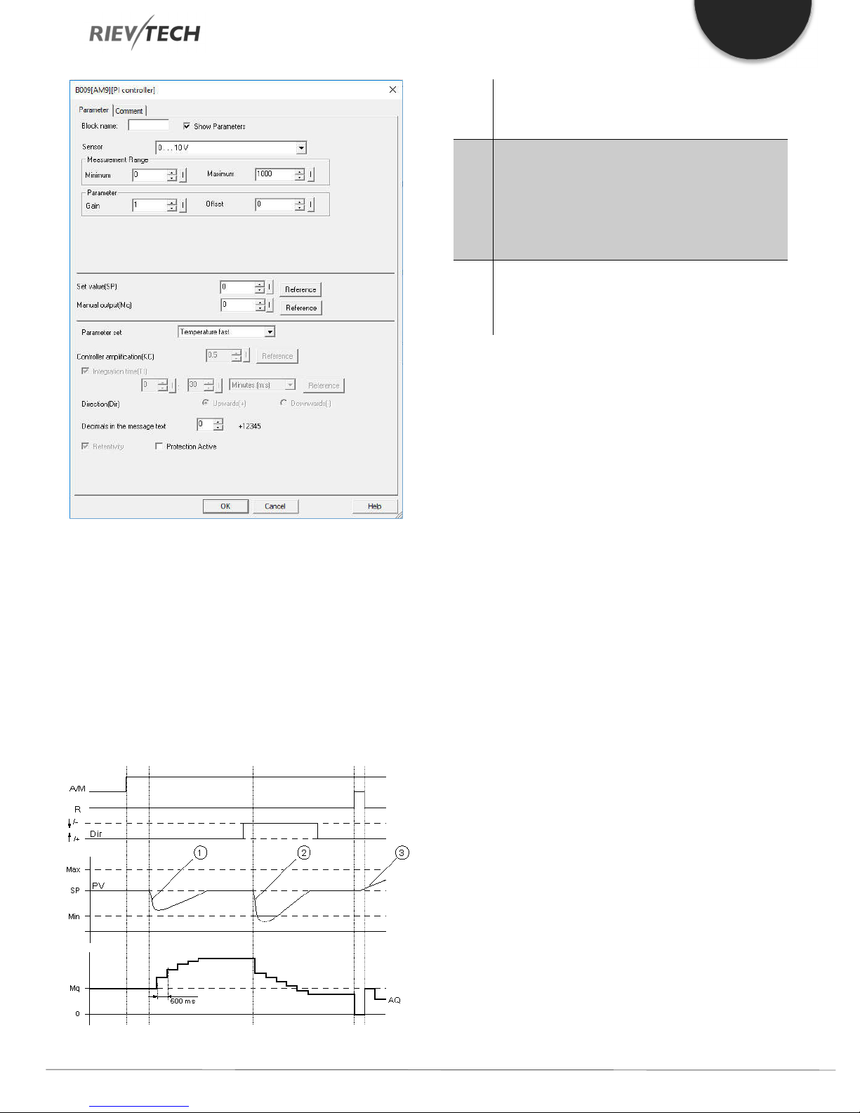
EN
1.
A disturbance causes the PV to drop, as Dir is
2.
A disturbance causes the PV to drop, as Dir is
3.
As AQ is set to 0 by means of the input R, PV
positioned upwards, AQ increases until PV
corresponds again to SP.
positioned downwards, AQ decreases until PV
corresponds again to SP.
Dir is coordinated with the basic conduct of a control
loop. The direction (dir.) cannot be changed during
the term of the function. The change in Dir here is
shown for the purposes of clarification.
changes. This is based on the fact that PV
increases, which on account of Dir = upwards
causes AQ to drop.
Description of Function
If the input A/M is set to 0, then the special function issues
output AQ with the value that you set with parameter Mq.
Parameter P (number of decimal places)
Only applies to portray the values from PV, SP, Min. and Max.
in a message text.
Timing Diagram
Nature, manner and speed with which the AQ changes
depend on the parameters KC and TI. Thus, the course of AQ
in the diagram is merely an example. A control action is
continuous; therefore, the diagram portrays just an extract.
If the input A/M is set to 1, then automatic mode commences.
As an integral sum the value Mq is adopted, the controller
function begins the calculations in accordance with the
formulas given in Control and regulated basics. The updated
value PV is calculated in the formulas.
Updated value PV = (PV * gain) + offset
If the updated value PV = SP, then the special function does
not change the value of AQ.
Dir = upwards/+ (timing diagram numbers 1 and 3)
If the updated value PV > SP, then the special function
reduces the value of AQ.
If the updated value PV < SP, then the special function
increases the value of AQ.
Dir = downwards/- (timing diagram number 2)
If the updated value PV > SP, then the special function
increases the value of AQ.
If the updated value PV < SP, then the special function
reduces the value of AQ.
With a disturbance, AQ continues to increase/decrease until
the updated value PV again corresponds to SP. The speed
with which AQ changes depends on the parameters KC and
TI. If the input PV exceeds the parameter Max., then the
updated value PV is set to the value of Max. If the PV falls short
of the parameter Min., then the updated value PV is set to the
Programmable Relay ● User Manual for ELC and PR Series 77 2018 v4.5 ● © Rievtech Co., Ltd. ● www.rievtech.com
value of Min.
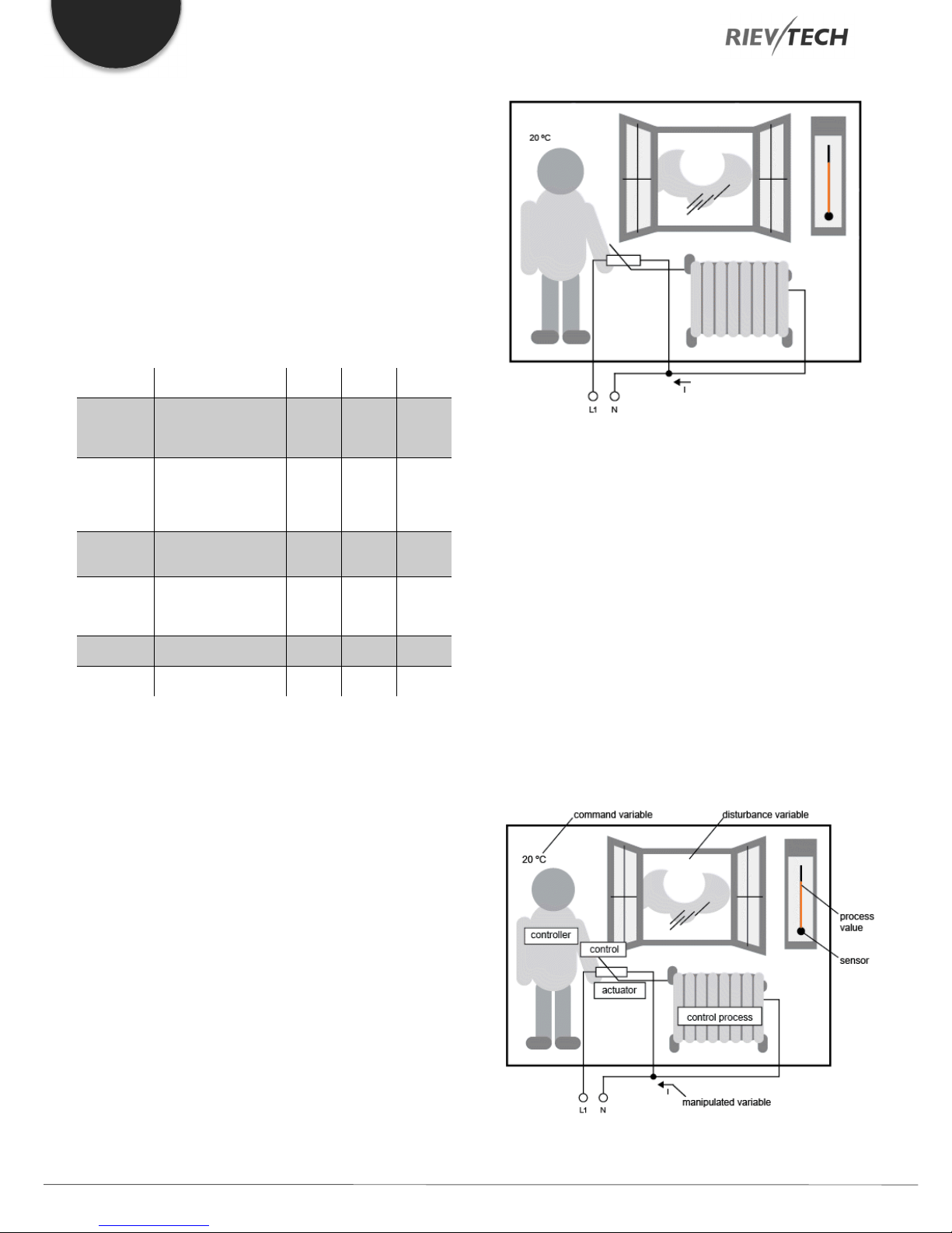
EN
Parameter
Parameter
Parameter
Temperature
Temperature
If the input R is set to 1, then the AQ output is reset. As long
as R is set, the input A/M is disabled.
Sampling Time
The sampling time is fixed at 500 ms.
Parameter sets
In order to simplify the use of the PI controller, the parameters
for KC, TI and Dir are predefined for the following applications:
Parameter set Application example
Temperature, cooling
fast
slow
Pressure 1
Pressure 2
Full level 1
Full level 2
control of small
spaces; small
volumes
Heating, ventilation,
temperature, cooling
control of large
spaces; large
volumes
Quick pressure
change, compressor
control
Slow pressure
change, differential
pressure control (flow
controller)
Vat and/or reservoir
filling without drain
Vat and/or reservoir
filling with drain
KC
0,5 30 +
1,0 120 +
3,0 5 +
1,2 12 +
1,0 1 +
0,7 20 +
TI (s)
Dir
Control and regulated
In engineering, quantities can be both controlled and
regulated.
When controlling, a quantity is manipulated without being able
to compensate for outside influences. When regulating, a
quantity is maintained at a specific value in order to
compensate for outside influences.
Basic concepts of regulating
In the example, the current for the electric heating is the
manipulated variable. The changeable resistance is the
actuator. The hand that operates the actuator is the control.
The actual room temperature is the controlled variable or the
process value. The desired room temperature is the command
variable or the setpoint value. The electric heating is the control
process. The thermometer is the sensor. The temperature loss
from opening the window is the disturbance variable.
So, this means that the person measures the process value
(room temperature) with the sensor (thermometer), compares
the process value (room temperature) with the command
variable (desired room temperature) and uses the actuator
(changeable resistance) to manually regulate the manipulated
variable (heating current), in order to compensate for the
disturbance variable (temperature drop from opening the
window). The person is, therefore, the controller.
In the following example, controlling means that the person
can set the heat output at a fixed value. The heater cannot
compensate for the drop in room temperature when a window
is opened.
In the example below, regulating means that the person can
increase the heat output if the room temperature drops to
below 20 °C. If the room temperature rises above 20 °C, the
heat output is reduced.
The control device is formed from the actuator and the control.
Programmable Relay ● User Manual for ELC and PR Series 78 2018 v4.5 ● © Rievtech Co., Ltd. ● www.rievtech.com
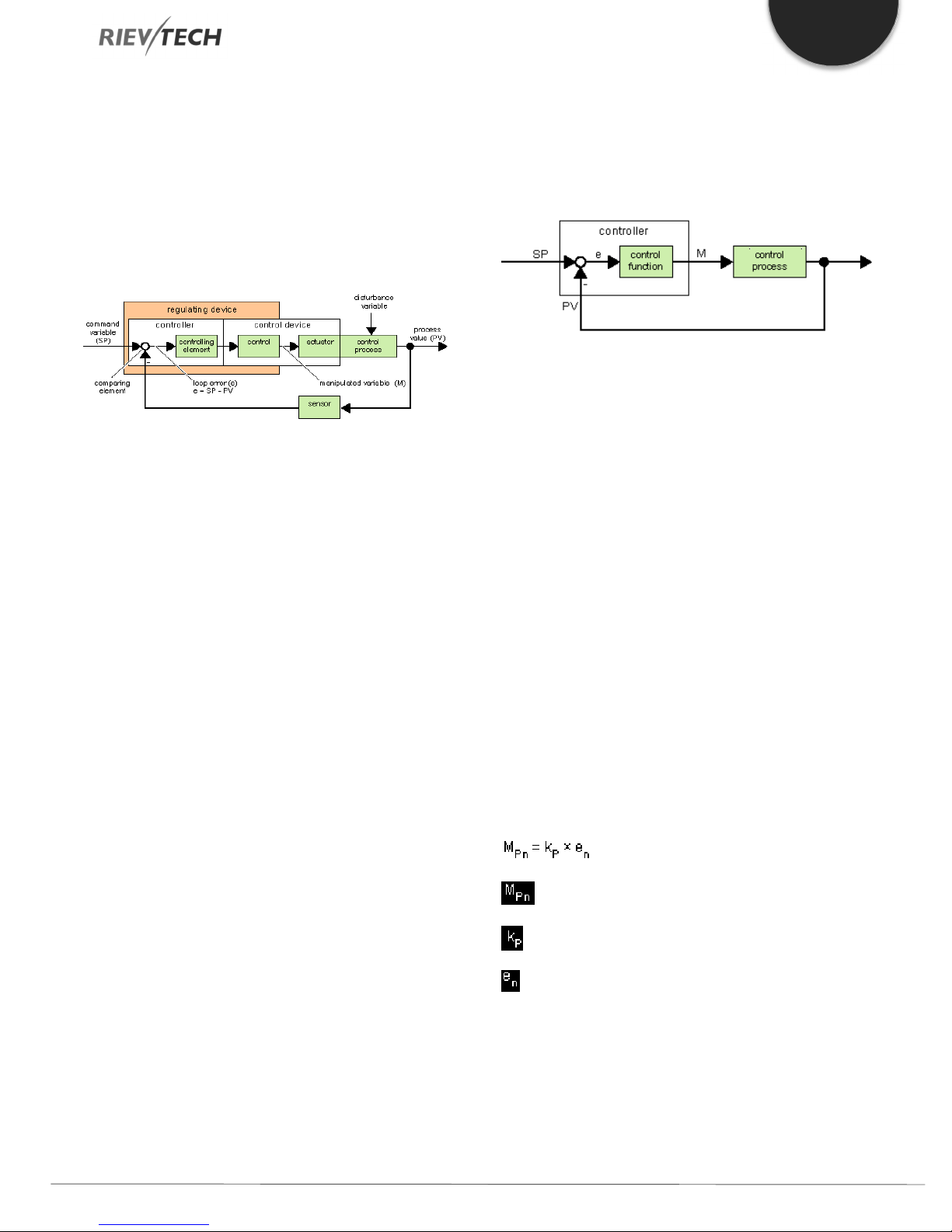
EN
The control and controller together form the regulating device.
The following picture gives an abstract portrayal of the
situation described above.
The comparing element uses the sensor to compare the
command variable with the process value. If the command
variables and process value deviate from one another, this
results in a positive or negative loop error that in turn changes
the process value.
Control loop
The process value x influences the manipulated variable M by
means of the regulating device. This creates a closed circuit
that is also known as a control loop.
If in the example above, the window is opened, the
temperature in the room drops. The person must increase the
heat output of the heater. If the heat output is increased too
much, it will get too hot. The person must then reduce the heat
output.
disturbance, a loop error arises. The loop error is corrected by
means of the manipulated variable M.
Controller basics
A controller can be simply portrayed as follows:
The comparing element and the controller function describe
the conduct of the controller.
The following describes the most important types of controller.
A controller's step response tells us a lot about its conduct.
The step response describes how a controller reacts to the
erratic change in the process value.
There are 3 important basic types of controller:
Proportional-action controller (P controller)
Integral-action controller (I controller)
Differential-action controller (D controller – we're not touching
on this here)
If the heat output is increased or reduced too quickly, then the
control loop starts to sway. The room temperature fluctuates.
It is either too hot or too cold. To prevent this, the person must
carefully and slowly reduce or increase the heat output.
Loop error
The loop error is the difference between the command variable
and the process value. In other words: the deviation of a
process value from a set value.
e = SP – PV
The loop error ‘e’ brings about a change to the manipulated
variable M.
The example above illustrates this very well: if the desired
temperature is 20 °C (= command value w), the room
temperature is 22 °C (= process value PV), this results in the
loop error:
e = SP – PV = 20 °C - 22 °C = -2 °C
In this case, the negative sign indicates a reversing action: the
heat output is reduced.
These are combined for a real controller. For instance, the PI
controller:
P Controller
A proportional-action controller (P controller) changes the
manipulated variable M proportional to the loop error. The P
controller works immediately. By itself, it cannot drive the loop
error to zero.
: Manipulated variable of the P controller at the time n
: Gain of the P controller
: Loop error at the time n
In a control loop's state of equilibrium, the loop error is zero or
very small. If the command variable changes or there is a
Programmable Relay ● User Manual for ELC and PR Series 79 2018 v4.5 ● © Rievtech Co., Ltd. ● www.rievtech.com

EN
The following picture shows a jump in process value and step
response of the controller:
Summary
The P controller has the following characteristics:
It cannot correct faults with the control process > lasting loop
error.
It reacts immediately to a change in the process value.
It is stable.
I Controller
An integral-action controller (I controller) changes the
manipulated variable M proportional to the loop error and to
the time. The I controller works by delayed action. It
completely remedies a loop error.
In order to calculate the value of the manipulated variable at a
period of time n, the time up until this period of time must be
divided into small time slices. The loop errors at the end of
each time slice must be added up (integrated) and they are
then entered in the calculation.
The following picture shows a jump in process value and step
response of the controller:
Summary
The PI controller has the following characteristics:
It sets the process value exactly to the command variable.
By so doing, it tends to oscillate and is unstable.
It requires more time to carry out the control action than the P
controller.
PI controller
A PI controller reduces the loop error immediately and will
eventually drive the loop error to zero.
: Manipulated variable at the time n
: Proportional part of the manipulated
variable
: Manipulated variable of the I controller at the time n
: Manipulated variable of the I controller at the time n-1;
also called the integral sum
: Gain of the I controller
: Sampling time, duration of a time slice
: Integral time: by means of this time, the influence of the
integral part is controlled by the manipulated variable, also
known as integral-action time
: Loop error at the time n
: Loop error at the time n-1; etc.
: Loop error at the beginning of the calculations
: Integral part of the manipulated variable
: Manipulated variable of the I controller at
the time n-1; also called the integral sum
: Gain of the P controller
: Gain of the I controller
: Sampling time, duration of a time slice
: Integral time; by means of this time the
influence of the integral part is controlled by the
manipulated variable, also known as the integralaction time
: Loop error at the time n
Programmable Relay ● User Manual for ELC and PR Series 80 2018 v4.5 ● © Rievtech Co., Ltd. ● www.rievtech.com
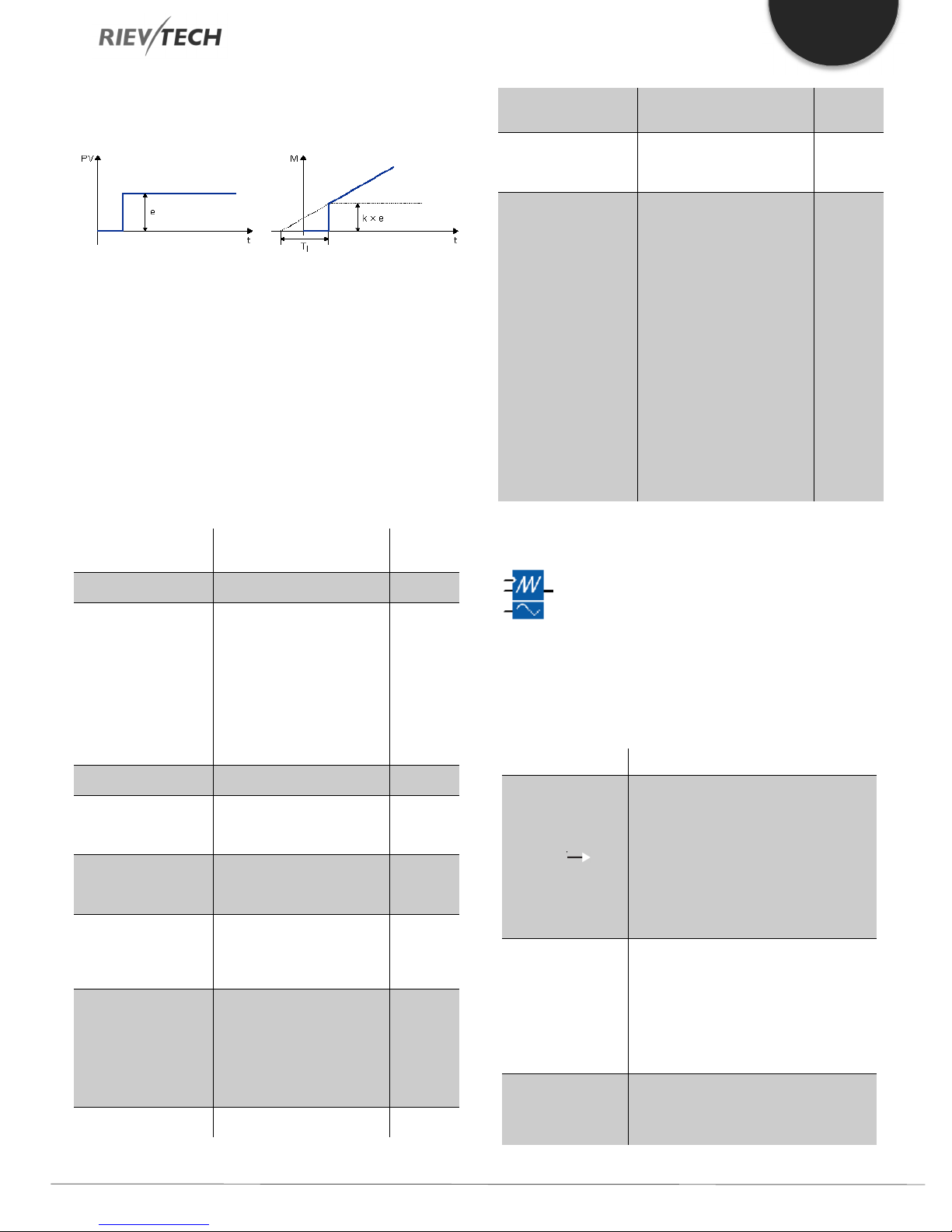
EN
The following picture shows a jump in process value and step
response of the controller:
Summary
The PI controller has the following characteristics:
The P controller components quickly intercept an occurring
loop error.
The I controller components can then remedy the
remaining loop error.
The controller components supplement each other so that
the PI controller works quickly and precisely.
Description of the individual parameters
Controller parameters Portrayed in xLogic
Mn Manipulated
variable at the time n
kP
The gain of the P part
kI
The gain of the I part
Ts Sampling time,
duration of a time slice
TI Integral time Parameter TI, if you set this
en
Loop error at the time
n; generally, applies: e
= SP – PV
SP The parameter SP is the set-
PV PV is the process value x and
The gain parameter
The output of the PI controller
block
In the xLogic, the parameter
KC applies as an increase for
the I part and the P part of
the controller equally.
Should you enter KC=0, then
the P part of the controller
switches off. In this special
case, k is automatically set to
1 for the I part. If KC = 0: kP
= 0 and kI = 1
If KC <> 0: kP = kI = KC
Fixed 500 ms
parameter to 99:59 min, then
you switch off the I part of the
controller.
Refer to SP and PV "
value assignment w. For this
parameter, you can use the
analogue output of a different
special function.
is calculated as follows:
PV = (analog value on input *
gain) + offset.
You can connect the input for
example by means of an
analogue input with a PT100
sensor.
influences PV
Possible
value range
in the xLogic
0 to
1,000
0.00 to
99.99
00:01
min to
99.59
min
-10,000
to
+20,000
"
0.0 to
10.0
The offset parameter
PV is restricted by the
The Dir parameter gives the
influences PV
parameters Min. and Max.
action direction of the
controller.
Positive means: If the set
value > process value then
the process value is
increased; if the set value <
process value then the
process value is reduced.
Negative means: If the set
value > process value then
the process value is reduced;
if the set value < process
value then the process value
is increased.
e.g. heat regulation: if the set
value is greater than the
process value (room is too
cold), the manipulated
variable increases the
process value.
Analogue Ramp
Description of function
The Analogue Ramp instruction allows the output to be
changed from the current level to a selected level at a specified
rate.
Connection Description
A change in the status from 0 to 1 at
input EN (Enable) applies the start/stop
level (Offset "B" + StSp) to the output
for 100 ms and starts the ramp
Input En ( )
operation to the selected level.
A change in the status from 1 to 0
immediately sets the current level to
Offset "B", which makes output AQ
equal to 0.
SeI = 0: The step 1 (level 1) is
selected.
SeI = 1: The step 2 (level 2) is
Input Sel
selected.
A change in the status of Sel causes
the current level to start changing to
the selected level at the specified rate.
A change in the status from 0 to 1 at
Input St
input St (Decelerated Stop) causes
the current level to decrease at a
constant rate until the start/stop level
-10,000
to
+20,000
In each
case: 10,000 to
+20,000
- or +
Programmable Relay ● User Manual for ELC and PR Series 81 2018 v4.5 ● © Rievtech Co., Ltd. ● www.rievtech.com

EN
(Offset "B" + StSp) is reached. The
Parameter
Output AQ
start/stop level is maintained for 100
ms and then the current level is set to
Offset "B", which makes output AQ
equal to 0.
Level1 and Level2: Levels to be
reached; value range for each level: 10,000 to +20,000
MaxL: a Maximum value that must
not be exceeded.
Value range: -10,000 to +20,000
StSp: Start/Stop offset: value that is
added to Offset "B" to create the
start/stop level. If the Start/Stop offset
is 0, then the start/stop level is Offset
"B").
Value range: 0 to +20,000
Rate: Speed with which level 1, level 2
or 0ffset is reached. Steps/seconds
are issued.
Value range: 1 to 10,000
A: Gain
Value range: 0 to 10,00
B: Offset
Value range: +- 10.000
p: Number of decimal places
Value range: 0, 1, 2, 3
The output AQ is scaled using the
formula:
(Current Level - Offset "B") / Gain "A"
Note: When AQ is displayed in
parameter mode or message mode, it
is displayed as an un-scaled value
(engineering units: current level).
The value range for AQ: 0...+32767
Parameter p (number of decimal places)
The level parameters Level1 and Level2 can be provided by
the value of another already-programmed function:
Analog comparator (Ax – Ay) Analog threshold trigger (Ax)
Analog amplifier (Ax) Analog multiplexer (AQ)
Analog ramp (AQ) Mathematic instruction (AQ)
PI controller (AQ) Up/down counter (Cnt)
Analog filter (AQ) Average value (AQ)
Max/Min (AQ) On-delay (Ta)
Off-delay (Ta) On-/off-delay (Ta)
Retentive on-delay (Ta) Wiping relay(pulse output) (Ta)
Edge triggered wiping relay (Ta)
Asynchronous pulse generator (Ta)
Stairway light switch (Ta) Multiple function switch (Ta)
Stopwatch (Ta)
Parameter p only applies for displaying the values of AQ, level
1, level 2, MaxL, StSp, and Rate in a message text.
Programmable Relay ● User Manual for ELC and PR Series 82 2018 v4.5 ● © Rievtech Co., Ltd. ● www.rievtech.com

EN
A timing diagram for AQ
Description of function
If the input En is set, then the function sets the value StSp +
Offset "B" for 100 ms.
Then, depending on the connection of Sel, the function runs
from the level StSp + Offset "B" to either level 1 or level 2 at
the acceleration set in Rate.
If the input St is set, the function runs to a level of StSp + B at
the acceleration set in Rate. Then the function holds the level
at StSp + Offset "B" for 100 ms. After 100 ms, the level is set
to Offset "B". output AQ. The scaled value (output AQ) is 0.
If the input St is set, the function can only be restarted once
the inputs St and En have been reset.
Connection Description
Input En ( )
Parameter
Output AQ
Enable the analogue math function
block.
V1: Value 1: First operand
V2: Value 2: Second operand
V3: Value 3: Third operand
V4: Value 4: Forth operand
Operator 1: First operator
Operator 2: Second operator
Operator 3: Third operator
Priority 1: Priority of the first operation
Priority 2: Priority of the second
operation
Priority 3: Priority of the third
operation
P: number of decimals
Range of values: 0,1,2,3
The output AQ is the result of the
equation formed from the operand
values and operators. AQ will be set
to 32767 if a divide by 0 or overflow
occurs, and -32768 if a negative
overflow (underflow) occurs.
If input Sel has been changed, depending on the connection
of Sel, the function runs from the current target level to the
new target level at the rate that is specified.
If the input En is reset, the function immediately sets the
current level to Offset "B".
The current level is updated every 100 ms. Note the
relationship between output AQ and the current level:
Output AQ = (current level – Offset "B" ) / Gain "A"
Analogue Math
Description of function
The analogue math block calculates the value AQ of an
equation formed from the user-defined operands and
operators.
Programmable Relay ● User Manual for ELC and PR Series 83 2018 v4.5 ● © Rievtech Co., Ltd. ● www.rievtech.com

EN
100 -
25 /(L) 2 +(M) 1
Parameter p (number of decimals)
The values V1, V2, V3, and V4 can be provided by the actual
value of another already-programmed function:
Analog comparator (Ax – Ay) Analog threshold trigger (Ax)
Analog amplifier (Ax) Analog multiplexer (AQ)
Analog ramp (AQ) Mathematic instruction (AQ)
PI controller (AQ) Up/down counter (Cnt)
Analog filter (AQ) Average value (AQ)
Max/Min (AQ) On-delay (Ta)
Off-delay (Ta) On-/off-delay (Ta)
Retentive on-delay (Ta) Wiping relay(pulse output) (Ta)
Edge triggered wiping relay (Ta)
Asynchronous pulse generator (Ta)
Stairway light switch (Ta) Multiple function switch (Ta)
Stopwatch (Ta)
Parameter p applies to the display of V1, V2, V3, V4, and AQ
in a message text.
of error that occurred. You can program an analogue math
error detection function block in your circuit program to detect
these errors, and to control the program behaviour as needed.
You program one analogue math error detection function
block to reference one specific analogue math function block.
Examples
The following tables show some simple example analogue
math block parameters, and the resulting equations and
output values:
V1 Operator1 V2 Operator2 V3 Operator3 V4
12 +(M) 6 /(H) 3 -(L) 1
Equation: (12 + (6 / 3)) - 1
Result: 13
V1 Operator1 V2 Operator2 V3 Operator3 V4
2 +(L) 3 *(M) 1 +(H) 4
Equation: 2+ (3*(1+4))
Result: 17
V1 Operator1 V2 Operator2 V3 Operator3 V4
(H)
Equation: (100 – 25) / (2 + 1)
Result: 25
Description of the function
The analogue math function combines the four operands and
three operators to form an equation. The operator can be any
one of the four standard operators: +, -, *, or /. For each
operator, you must set a unique priority of High ("H"), Medium
("M"), or Low ("L"). The high operation will be performed first,
followed by the medium operation, and then by the low
operation. You must have exactly one operation of each
priority. The operand values can reference another previouslydefined function to provide the value. The analogue math
function rounds the result to the nearest integer value.
The number of operand values is fixed at four and the number
of operators is fixed at 3. If you need to use fewer operands,
use constructions such as " + 0" or " * 1" to fill the remaining
parameters.
You can also configure the behaviour of the function when the
Enable parameter "En"=0. The function block can either retain
its last value or be set to 0.
Possible errors: Zero division and overflow
If the analogue math function block execution results in zero
division or overflow, it sets internal bits that indicate the type
Analogue Math Error Detection
Description of function
The analogue math error detection block sets an output if an
error has occurred in the referenced analogue math function
block.
Connection Description
Input En ( )
Enable the analogue math error
detection function block.
Input R ( ) Reset the output
Referenced FB: block number of an
analogue math instruction
Error to detect: Zero division,
Parameter
Overflow, or Zero division OR
Overflow.
Auto Reset: Reset the output when
the failure condition clears.
Programmable Relay ● User Manual for ELC and PR Series 84 2018 v4.5 ● © Rievtech Co., Ltd. ● www.rievtech.com

EN
Sn (Number of samples): determines
Q is set high if the error to detect
Output Q
occurred in the last execution of the
referenced analogue math function
block.
Parameter Referenced FB
bit set by the analogue math instruction at the end of its
execution: 1 if the error occurred, 0 if not. OF represents the
overflow bit set by the analogue math instruction: 1 if the error
occurred, 0 if not. Zero division OR Overflow represents the
logical OR of the zero division bit and the overflow bit of the
referenced analogue math instruction. Output (Q) represents
the output of the analogue math error detection function. An
“x” indicates that the bit can be either 0 or 1 with no influence
on the output.
Error to Detect Zero Of Output
Zero division 1 X 1
Zero division 0 X 0
Overflow X 1 1
Overflow X 0 0
Zero division OR Overflow 1 0 1
Zero division OR Overflow 0 1 1
Zero division OR Overflow 1 1 1
Zero division OR Overflow 0 0 0
If the Referenced Analog Math FB is null, then the output is
always 0.
The value for the Referenced FB parameter references the
block number of an already-programmed analogue math
function block.
Description of the function
The analogue math error detection block sets the output when
the referenced analogue math function block has an error. You
can program the function to set the output on a zero division
error, an overflow error, or when either type of error occurs.
If you select the automatically reset checkbox, the output is
reset prior to the next execution of the function block. If not,
the output retains its state until the analogue math error
detection block is reset with the R parameter.
In any scanning cycle, if the referenced analogue math
function block executes before the analogue math error
detection function block, the error is detected in the same
scan cycle. if the referenced analogue math function block
executes after the analogue math error detection function
block, the error is detected in the next scan cycle.
Analogue math error detection logic table
In the table below, Error to Detect represents the parameter
of the analogue math error detection instruction that selects
which type of error to detect. Zero represents the zero division
Analogue Filter
Description of function
Connection Description
Analogue Inputs
Analogue Outputs
Input Ax
Parameter
Analogue Flags
The block number of a function with
analogue output
how many analogue values are
sampled within the program cycles
that are determined by the set number
of samples. xLogic samples an
analogue value within every program
cycle. The number of program cycles
is equal to the set number of samples.
Possible settings:
8, 16, 32, 64, 128, 256
Programmable Relay ● User Manual for ELC and PR Series 85 2018 v4.5 ● © Rievtech Co., Ltd. ● www.rievtech.com

EN
Output AQ
AQ outputs an average value of the
analogue input Ax over the current
number of samples, and it is set or
reset depending on the analogue
input and the number of samples.
* Analog inputs: 0 to 10 V
corresponds with 0 to 1000 (internal
value).
Description of function
The function outputs the average value after sampling the
analogue input signal according to the set number of samples.
This SFB can reduce the error of the analogue input signal.
NOTICE:
There is a maximum of eight analogue filter function
blocks available for use in the circuit program in xLogicsoft.
Max/Min
Description of function
Connection Description
The function of input En (Enable)
Input En ( )
depends on the settings of parameter
Mode and the selection of checkbox
"when En = 0, reset Max/Min".
Parameter
You can set the number of samples to the following values:
After you set the parameter, the analogue filter calculates the
average value of the samples and assigns this value to AQ.
Timing diagram
Input S1
Input Ax
Parameter
This input is enabled when you set
Mode =2:
A positive transition (0 to 1) at input S1
sets the output AQ to the maximum
value.
A negative transition (1 to 0) at input S1
sets the output AQ to the minimum
value.
Input Ax is one of the following
analogue signals:
Analog Inputs
Analog Outputs
Analogue flags
Block number of a function with
analogue output
Mode
Possible settings: 0, 1, 2, 3
Mode = 0: AQ = Min
Mode = 1: AQ = Max
Mode = 2 and S1= 0 (low): AQ = Min
Mode = 2 and S1= 1 (high): AQ = Max
Mode = 3 or a block value is
referenced: AQ = Ax
AQ outputs a minimum, maximum, or
actual value depending on the inputs,
Output AQ
Programmable Relay ● User Manual for ELC and PR Series 86 2018 v4.5 ● © Rievtech Co., Ltd. ● www.rievtech.com
or is reset to 0 is configured to do so
when the function is disabled
Analog inputs: 0 to 10 V corresponds
with 0 to 1000 (internal value).

Timing diagram
EN
Parameter Mode
You can set the values for parameter Mode based on the
actual values of another already-programmed function:
Analog comparator (Ax – Ay) Analog threshold trigger (Ax)
Analog amplifier (Ax) Analog multiplexer (AQ)
Analog ramp (AQ) Mathematic instruction (AQ)
PI controller (AQ) Up/down counter (Cnt)
Analog filter (AQ) Average value (AQ)
Max/Min (AQ) On-delay (Ta)
Off-delay (Ta) On-/off-delay (Ta)
Retentive on-delay (Ta) Wiping relay(pulse output) (Ta)
Edge triggered wiping relay (Ta)
Asynchronous pulse generator (Ta)
Description of the function
If you select the check box "when En = 0, reset Max/Min":
En = 0: The function sets the AQ value to 0.
En = 1: The function outputs a value at AQ, depending on the
settings of Mode and S1.
If you do not select the checkbox "when En = 0, reset
Max/Min":
En = 0: The function holds the value of AQ at the current value.
En = 1: The function outputs a value at AQ, depending on the
settings of Mode and S1.
Mode = 0: The function sets AQ to the minimum value
Mode = 1: The function sets AQ to the maximum value
Mode = 2 and S1 = 0: The function sets AQ to the minimum
value
Mode = 2 and S1 = 1: The function sets AQ to the maximum
value
Stairway light switch (Ta) Multiple function switch (Ta)
Stopwatch (Ta)
You can select the required function by the block number.
Programmable Relay ● User Manual for ELC and PR Series 87 2018 v4.5 ● © Rievtech Co., Ltd. ● www.rievtech.com
Mode = 3 or a block value is referenced: The function outputs
actual analogue input value.

EN
St (Sampling time): You can set it to
Max/Min block upper/lower function
In the dialogue box of Max/Min block, there is an upper/lower
limit setting, when the block output the AQ value is less than
the lower value, the AQ shall be equal to the Lower value;
While the block output the AQ value is more than the upper
value, the AQ shall be equal to the upper value.
If someone wants to use the upper/lower limitation for other
function blocks. such upper/lower limit function can be used,
then this block can be referenced as other blocks parameters
when programming.
Here is an example:
Someone wants to use the panel key to change the on-delay
parameters for 1s—10s in the text message block, if the value
which user set exceeds such range, then it will crush the
machine, hence we must add the upper/lower limitation in the
program to avoid such trouble.
Output AQ
The range of values:
If St = Seconds: 1 to 59
If St = Days: 1 to 365
If St = Hours: 1 to 23
If St = Minutes: 1 to 59
Sn (Number of samples):
The range of values:
If St = Seconds: 1 to St*100
If St = Days: 1 to 32767
If St = Hours: 1 to 32767
If St = Minutes and St ≤ 5 minutes: 1 to
St*6000
If St = Minutes and St ≥ 6 minutes: 1
to 32767
AQ outputs the average value over the
specified time of sampling.
* Analog Inputs: 0 to 10 V
corresponds with 0 to 1000 (internal
value).
Average Value
Description of function
The average value function samples the analogue input signal
during the configured time period and outputs the average
value at AQ.
Connection Description
A positive edge (0 to 1 transition) at
input En (Enable) sets the output AQ to
Input En ( )
Input R ( )
Parameter
the average value of input Ax after the
configured time. A negative edge (1 to
0 transition) holds the output at its last
calculated value.
A positive edge (0 to 1 transition) at
input R (Reset) resets the output AQ to
0.
Seconds, Days, Hours or Minutes.
Parameter St and Sn
Parameter St represents the sampling time and parameter Sn
represents the number of samples.
Programmable Relay ● User Manual for ELC and PR Series 88 2018 v4.5 ● © Rievtech Co., Ltd. ● www.rievtech.com

Timing diagram
0
0 x Status unchanged
0
1 0 Reset
1
0 1
Set
1
1 0 Reset
Description of the function
When En = 1, the average value function calculates the
average value of the samples during the configured time
interval. At the end of the sampling time, this function sets
output AQ to this calculated average value.
When En = 0, the calculation stops, and AQ retains the last
calculated value. When R = 0, AQ is reset to 0.
EN
Timing diagram
Latching Relay
Description of function
A signal at input S sets output Q. A signal at input R resets
output Q.
Connection Description
Input S ( )
Set output Q with a signal at input S
(Set).
Reset output Q with a signal at input
Input R ( )
R (Reset). Output Q is reset if S and R
are both set (reset has priority over
set).
Parameter
Retentivity set (on) = the status is
retentive in memory.
Q is set with a signal at input S and
Output Q
remains set until it is reset with a
signal at input R.
No parameter of a Latching relay can be set/modified in
runtime mode.
Description of the function
The latching relay represents a simple binary memory logic.
The output value depends on the input states and the previous
status at the output.
Logic table of the latching relay:
S R Q Remark
When retentivity is enabled, the output signal corresponds to
the signal status prior to the power failure.
Pulse Relay
Description of function
The output is set and reset with a short one-shot at the inputs
S and R respectively.
Programmable Relay ● User Manual for ELC and PR Series 89 2018 v4.5 ● © Rievtech Co., Ltd. ● www.rievtech.com
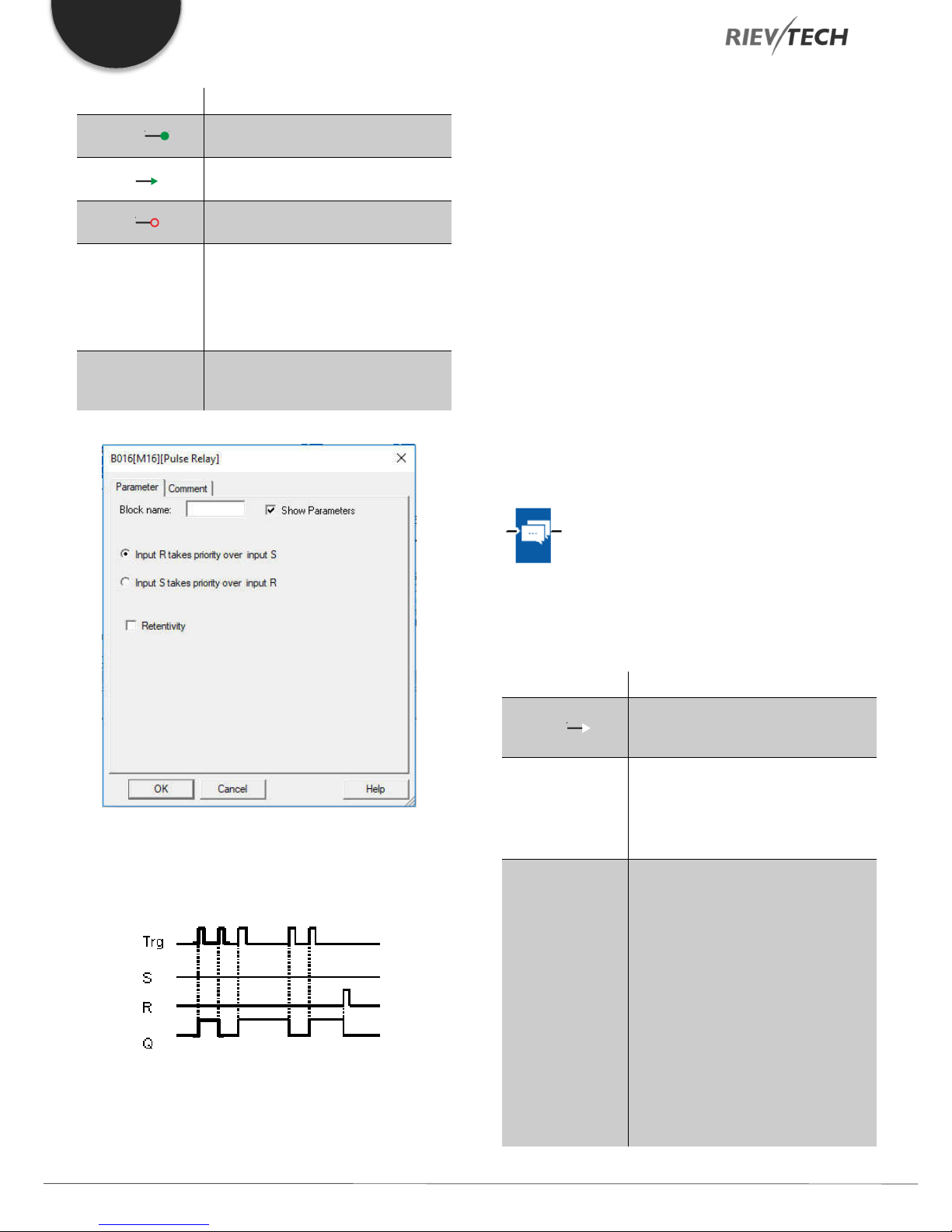
EN
Connection Description
Trg input ( )
Input S ( )
Input R ( )
Parameter
Output Q
You switch output Q on or off with a
signal at input Trg (Trigger) input.
A one-shot at input S (Set) sets the
output to logical 1.
A one-shot at input R (Reset) resets
the output to logical 0
Selection:
RS (input R priority), or
SR (input S priority)
Retentivity set (on) = the status is
retentive in memory.
Q is switched on with a signal at Trg
and is reset again at the next Trg
pulse if both S and R = 0.
Description of the function
The status of output Q changes with each 0 to 1 transition at
input Trg and if both S and R = 0, i.e. the output is switched
on or off.
Input Trg does not influence the SFB when S = 1 or R = 1.
A one-shot at input S sets the pulse relay, i.e. the output is set
to logical 1.
A one-shot at input R resets the pulse relay to its initial state,
i.e. the output is set to logical 0.
Either the input R takes priority over input S (i.e. the signal at
input S has no effect as long as R = 1), or the input S takes
priority over input R (i.e. the signal at input R has no effect as
long as S = 1), depending on your configuration.
Message Text
No parameter of Latching relay can be set/modified in runtime
mode.
Timing diagram
Description of function
Display message texts and parameters of other blocks in RUN
mode.
Connection Description
Input En ( )
Input P
Parameter
A 0 to 1 transition at En (Enable)
triggers the output of the message
text.
P is the priority of the message text.
1 is the lowest, 32 is the highest
priority.
Quit: Acknowledgement of the
message text
Text: Input of the message text
Par: Parameter or actual value of
another, already configured function
(see "Visible parameters or actual
values")
Time: Shows the continuously
updated time-of-day
Programmable Relay ● User Manual for ELC and PR Series 90 2018 v4.5 ● © Rievtech Co., Ltd. ● www.rievtech.com
Date: Shows the continuously updated
date
EnTime: Shows the time of the 0 to 1
transition

EN
EnDate: Shows the date of the 0 to 1
Output Q
Q remains set as long as the message
text is queued.
You can press the and keys to step through multiple
active message texts.
Example
This is how two message texts could be shown:
Display field of xLogic in RUN mode
Input P configuration
From the input P, you configure the following characteristics of
the message text:
Description of the function
With a 0 to 1 transition of the signal at input En, the display
outputs your configured message text (actual value, text, TOD,
date) in RUN mode.
Acknowledgement disabled (Ack = Off):
The message text is hidden with a 0 to 1 signal transition at
input En.
Acknowledgement enabled (Ack = On):
After input En is reset to 0, the message text is displayed until
acknowledged by pressing the OK button. The message text
cannot be acknowledged as long as input En is high.
If several message text functions were triggered with En=1,
the message with the highest priority (1 = lowest, 64=highest)
is displayed. This also implies that a new message text is only
displayed if its priority is higher than that of previously enabled
message texts.
After a message text is disabled or acknowledged, the
function automatically shows the previously active message
text with the next highest priority.
● Priority
● Acknowledgement
● Message destination
Restrictions
Up to 128 message text functions are available for PR-12, PR18/ELC-22/PR-24.
Programmable Relay ● User Manual for ELC and PR Series 91 2018 v4.5 ● © Rievtech Co., Ltd. ● www.rievtech.com

EN
Shows the parameters of a block selected from the
Particular characteristics to be noted when configuring
"Blocks" area which you can output in the message
text.
1 "General" area
Here you will find the following settings: ·
Priority of the message text
Check box for message text
acknowledgement
2 Kinds of parameters and the number size selection
area
IO status, analogue IO values analogue flags and blocks
can be inserted into LCD for displaying.
3 "Blocks" area
Shows a list of all the circuit program blocks and their
parameters.
4 Language selection
5 Animate option
This option is used for display animation on the ELC43TS. See user manual of ELC-43TS for further details.
6 "Insert" button
Button for inserting a parameter selected from the
“Block parameters” area.
"Block parameters" or "General parameters" area into
the message text.
7 "Block parameters" area
8 "General parameters" area
Shows general parameters such as the current date.
9 "Delete" button
Button for deleting entries from the "Messages" area
"Special characters" button
Button for inserting special characters in the
"Messages" area
10 "Messages" area
You arrange the message text in this area. Information
entered in this area corresponds with that on the
xLogic display.
To arrange the message text
From the "Blocks" area, select the block whose parameters
you want to output.
Drag and drop the parameters required from the "Block
parameters" to the "Messages" area. You may also use the
"Insert" button to do so.
In the "Messages" area, you can add parameter data as
required.
Particular characteristics to be noted when configuring
The message text can be configured in the block properties
dialogue. You can enter up to 4 lines for each message text
(the text display of the xLogic has 4 x 16 characters) and set
the priority. You can move to the next line using the cursor keys
or the mouse. Hit the [ENTER] key to confirm all your entries
in the block properties dialogue and to close the dialogue.
You may also enter the actual values of other blocks in the text
lines. To do so, select the relevant block from the Block
dialogue. A Parameter dialogue opens to display a list of all
parameters available for the selected block. The block
parameter you select in this dialogue is written to the selected
text line. The actual parameter value is now included when you
call the message text.
Set the "Acknowledge message" attribute to specify whether
a message is being acknowledged before it is closed.
Programmable Relay ● User Manual for ELC and PR Series 92 2018 v4.5 ● © Rievtech Co., Ltd. ● www.rievtech.com
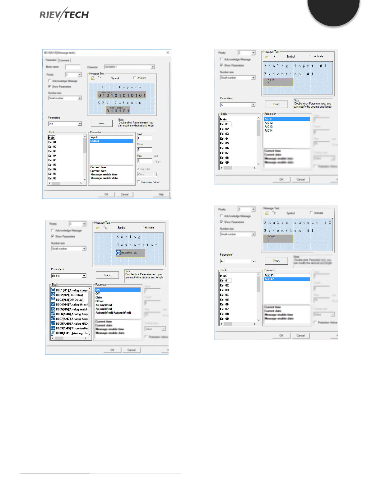
EN
A. I/O status of CPU and extensions
B. Blocks
C. Analog input value of CPU and extensions
D. The analogue output value of CPU and extensions
Programmable Relay ● User Manual for ELC and PR Series 93 2018 v4.5 ● © Rievtech Co., Ltd. ● www.rievtech.com
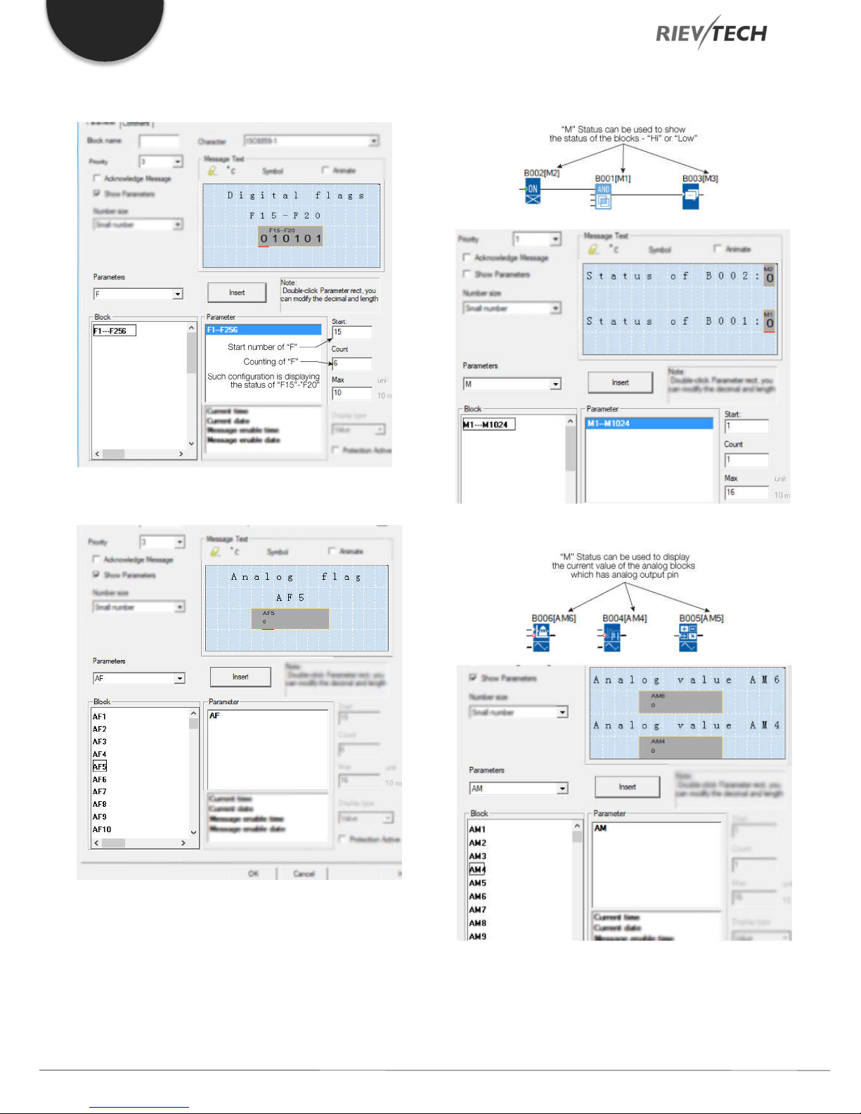
EN
E. F (digital flag) status
G. M status
F. AF (analogue flag) value
H. AM value
Programmable Relay ● User Manual for ELC and PR Series 94 2018 v4.5 ● © Rievtech Co., Ltd. ● www.rievtech.com
With a text message, the text can be displayed as a large
number (6 bits or 4 bits). This feature can only be used in PR12, PR-18, ELC-22, PR-24 and PR-26 Series CPUs.
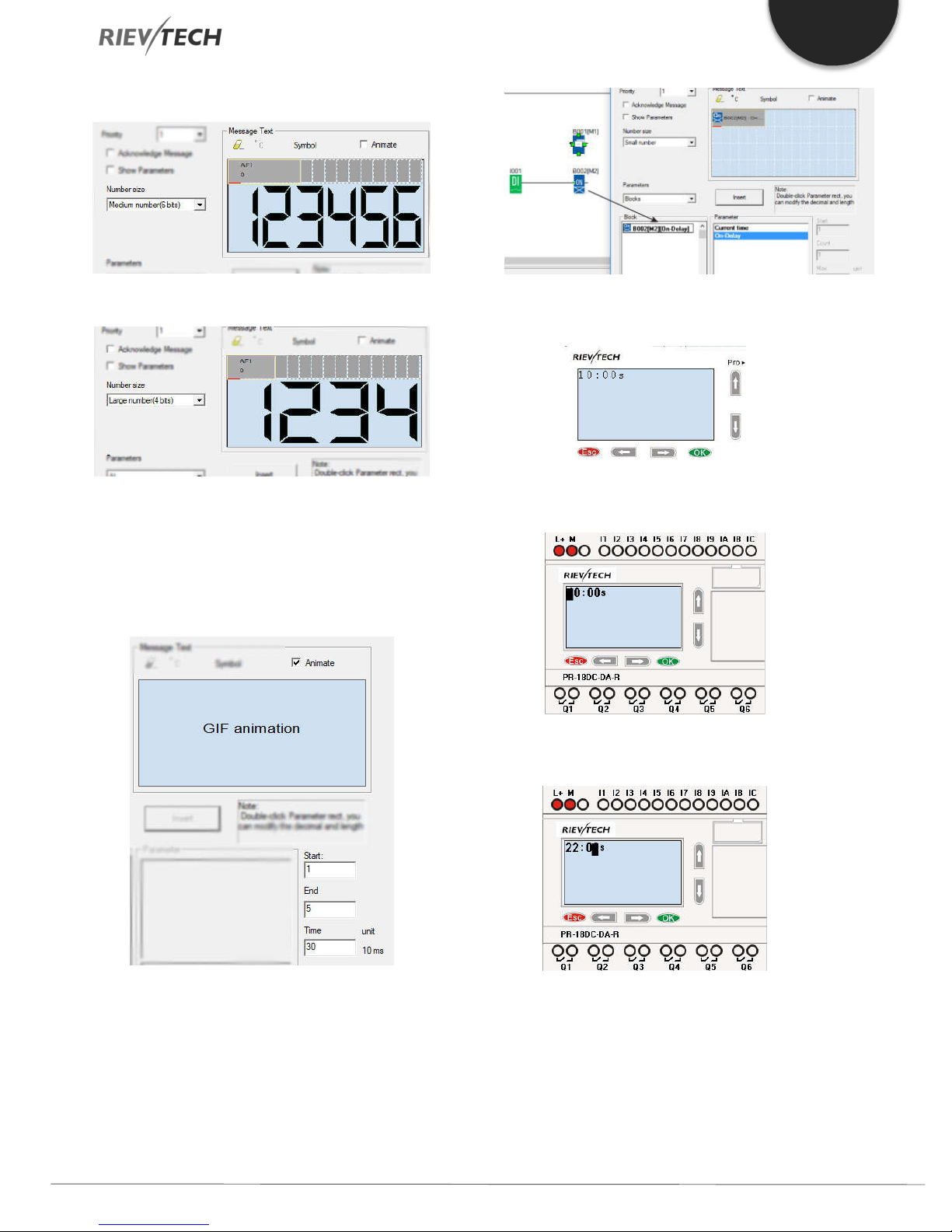
6-bit
EN
4-bit
Animate option
This option is for the ELC-43TS touch screen, it is used to
trigger the pictures saved in the screen, please refer to the
ELC-43TS User Guide for detailed information.
B. Change the page to display the message text
contents using the arrow keys.
C. Press “OK” for 3 seconds to enter into edit
mode.
How to change the parameters of blocks in a displayed
message?
To change the parameters of a displayed message,
press “OK” key for 3 seconds.
Steps to Follow:
A. Insert the parameters of the block into the
message text. (Here is an On-delay).
D. Modify the value by pressing the arrow keys
and confirm with the OK key.
CPU Cover
This block cannot be found in the block list as it is set as
default by the system of xLogic. To change the CPU Cover
text, use your mouse and click “Tools” menu->select “Edit
Cover HMI” in xLogicsoft.
Programmable Relay ● User Manual for ELC and PR Series 95 2018 v4.5 ● © Rievtech Co., Ltd. ● www.rievtech.com

EN
Type: Sets either a pushbutton action
Retentivity set (on) = the status is
Description of function
Display the status (Run or Stop) of xLogic when power-on or
simulation by software.
Particular characteristics to be noted when configuring
On the PLC’s sceen:
Output Q
retentive in memory.
Output Q remains set 1, as long as
En=1 and the status at the parameter
Type = Switch and Status = On.
Output Q is set for the duration of one
cycle if EN=1 and the status at the
parameters Type = momentary
(pushbutton) and Status = On.
Softkey
Description of function
This SFB provides the action of a mechanical pushbutton or
switch.
Connection Description
Output Q is set with a 0 to 1 signal
Input En ( )
Parameter
transition at input En (Enable) and if, in
addition, 'Status=On' has been
confirmed in configuration mode.
for one cycle or a switching action of
the function.
Status: On or Off state that is applied
in the initial cycle after program startup, is retentivity is not set.
Factory state
The default of 'Type' is 'momentary action switch'.
Timing diagram
Description of the function
The output is set, when input En is set and the 'Status'
parameter is set to 'On' and confirmed with OK. This action is
performed irrespective of a configured switch or pushbutton
function.
The output is reset to '0' in the following three cases:
1. With a 1 to 0 signal transition at input En.
2. When a pushbutton function is configured, and one cycle
has expired after its actuation.
3. When the 'Status' parameter sets the 'Off' status in
configuration mode, and this has been confirmed with OK.
Programmable Relay ● User Manual for ELC and PR Series 96 2018 v4.5 ● © Rievtech Co., Ltd. ● www.rievtech.com

EN
Shift register bit that determines the
Particular characteristics to be noted when configuring
The softkey can be used both with momentary push button or
switching action. At the status parameter, you can define the
on (actuated) or off state for the switch/push button.
If the softkey is assigned a push button action, the output is
always set for the duration of one cycle with a 0 to 1 transition
at input En when the push button is in on state, or if the push
button state changes from Off to On when En=1.
Parameters of softkey in message texts block:
1. The “ok” means you can press the ok button to switch the
status of the softkey block after its parameter inserted into
message texts.
2. The “Esc” means you can press the ESC button to switch
the status of the softkey block after its parameter inserted
into message texts.
3. The status of softkey block is also can be inserted into the
message texts block for displaying.
Trg input ( )
Input Dir
Parameter
Output Q
The SFB is started with a positive edge
(0 t 1 transition) at input Trg (Trigger). A
1 to 0 transition is irrelevant.
You define the shift direction of the
shift register bits S1...S8 at the Dir
input:
Dir = 0: shift up (S1 >> S8)
Dir = 1: shift down (S8 >> S1)
value of output Q.
Possible settings: S1 ... S8
Retentivity set (on) = the status is
retentive in memory.
The output value corresponds to the
configured shift register bit.
Shift Register
Description of function
The shift register function can be used to read an input value
and to shift the bits. The output value corresponds to the
configured shift register bit. The shift direction can be changed
at a special input.
Connection Description
Input In The function when started reads this
input value.
Timing diagram
Setting the Par parameter
This special function is not available in parameter assignment
mode.
Programmable Relay ● User Manual for ELC and PR Series 97 2018 v4.5 ● © Rievtech Co., Ltd. ● www.rievtech.com

EN
A: Gain
Description of function
The function reads the value of input In with a positive edge (0
to 1 transition) at input Trg (Trigger).
This value is written to shift register bits S1 or S8, depending
on the set shift direction:
Shift up: S1 accepts the value of input In; the previous
value of S1 is shifted to S2, S2 is shifted to S3, etc.
Shift down: S8 accepts the value of input In; the
previous value of S8 is shifted to S7, S7 is shifted to S6,
etc.
Q outputs the value of the configured shift register bits.
If retentivity is not enabled, the shift function restarts at S1 or
S8 after a power failure.
NOTICE:
The special function shift register can be used only
once in the circuit program.
Pulse Width Modulator (PWM)
Description of function
The Pulse Width Modulator (PWM) instruction modulates the
analogue input value Ax to a pulsed digital output signal. The
pulse width is proportional to the analogue value Ax.
Connection Description
A positive edge (0 to 1 transition) at
Input En ( )
input En enables the PWM function
block.
Input Ax
Analog signal to be modulated to a
pulsed digital output signal.
Range of values: +- 10.00
B: Zero offset
Range of values: +- 10,000
Parameter
PT: Periodic time over which the
digital output is modulated
p: Number of decimals
Range of values: 0, 1, 2, 3
Q is set or reset for the proportion of
Output Q
each time period according to the
proportion of the standardized value
Ax to the analogue value range.
Parameter PT
The periodic time PT can be provided by the actual value of
another already-programmed function:
Analog comparator (Ax – Ay) Analog threshold trigger (Ax)
Analog amplifier (Ax) Analog multiplexer (AQ)
Analog ramp (AQ) Mathematic instruction (AQ)
PI controller (AQ) Up/down counter (Cnt)
Analog filter (AQ) Average value (AQ)
Max/Min (AQ) On-delay (Ta)
Off-delay (Ta) On-/off-delay (Ta)
Retentive on-delay (Ta) Wiping relay(pulse output) (Ta)
Edge triggered wiping relay (Ta)
Asynchronous pulse generator (Ta)
Programmable Relay ● User Manual for ELC and PR Series 98 2018 v4.5 ● © Rievtech Co., Ltd. ● www.rievtech.com

EN
Stairway light switch (Ta) Multiple function switch (Ta)
Stopwatch (Ta)
Parameter p (number of decimals)
Parameter p applies only to the display of the Ax value in a
message text.
Description of the function
The function reads the value of the signal at the analogue input
Ax.
This value is multiplied by the value of parameter A (gain).
Parameter B (offset) is added to the product, as follows:
(Ax * Gain) + Offset = Actual value Ax
The function block calculates the proportion of the value Ax to
the range. The block sets the digital output Q high for the same
proportion of the PT (periodic time) parameter and sets Q low
for the remainder of the time period.
Examples of Timing Diagrams
The following examples show how the PWM instruction
modulates a digital output signal from the analogue input
value:
Example 1
The digital output of the PWM function is 3 seconds high, 7
seconds low, 3 seconds high, 7 seconds low and continues
in that pattern as long as parameter "En" = high.
Calculation rule
Q = 1, for (Ax – Min) / (Max – Min) of time period PT
Q = 0, for PT – [(Ax – Min) / (Max – Min)] of time period PT.
Note: Ax in this calculation refers to the actual value Ax as
calculated using the Gain and Offset. Min and Max refer to the
minimum and maximum values specified for the range
Special feature.
The standard output frequency of xLogic is up to 30Hz. By
configuring the PWM function block as shown below a
frequency of up to 10 kHz can be obtained on the following
CPU outputs:
PR-12 – Outputs Q3 and Q4
PR-18 and ELC-22 (PNP Transistor) – Outputs Q5 and Q6
PR-24 and PR-26 – Outputs Q7 and Q8
By the following configuration:
Analog input value: 500 (range 0...1000)
Periodic time T: 4 seconds
The digital output of the PWM function is 2 seconds high, 2
seconds low, 2 seconds high, 2 seconds low and continues
in that pattern as long as parameter "En" = high.
If the special output is selected in the property dialogue box of
PWM block, then the unit of “periodic time” will be changed
from s:1/100s to s:1/1000s, so if you input 3 (1/1000s), then
its frequency will be 1000/3 Hz.
Example 2
Analog input value: 300 (range 0...1000)
Periodic time T: 10 seconds
Programmable Relay ● User Manual for ELC and PR Series 99 2018 v4.5 ● © Rievtech Co., Ltd. ● www.rievtech.com
NOTICE:
1. The periodic time must be no less than 3 ms.
2. If the specific output is selected in the property
dialogue box of PWM block, then the output pin of the PWM
function block cannot be linked as an input to other blocks.
3. Q3, Q4 in the above dialogue box correspond to
Q3, Q4 of a PR-12 CPU or Q5, Q6 of a PR-18 and ELC-22
CPUs or Q7 and Q8 of the PR-24 and PR-26 CPUs.

EN
4. The output frequencies of the special channels of
the CPUs can be different ONLY if ONE box is ticked. If
BOTH boxes are ticked, the outputs will have the same
maximum frequency.
Modbus Read
Description of function
When there is a high level at En, the Modbus Read block will
be activated and the xLogic shall communicate with a
peripheral device as a master via RS232 or RS485 interface.
Furthermore, the output will be switched on when
communication is established successfully. Otherwise, the
output (Q pin) remains “off” which means communication has
failed.
A signal at input R resets output Q and disables this block at
the same time
Connection Description
A high signal at En input will enable
Input En ( )
“Modbus Read” function block to be
activated
04 Read Input Registers(3x)
Register start address, count
Q is set or reset depending on the
Output Q
NOTICE:
Data register Index: High Low /Low High
For example, when the HighLow index is set, and the data
0x0012 was read and saved to AQ, then AQ= 0X0012;
however, when the LowHigh index is set, then AQ= 0x1200.
Refer to the Modbus RTU Communication Manual for more
information.
Description of the function:
In the configuration of our xLogic communication, the xLogic
usually serves as a slave via Modbus RTU Protocol and can
communicate with a master directly. That’s to say, any device
communicating with xLogic sends a command to it, and then
its response will be sent out only when the xLogic has received
the command, just as the below figure shows:
communication status.
Successful communication, Q=1;
Failed communication, Q=0;
Input R ( )
Parameter
To disable the MODBUS read function
and set the output to 0 via the R (Reset)
input. Reset has priority over En
Slave address: 1 is a default.
Communication protocol: Modbus
(RTU)
Communication parameter: baud
rate (BPS), Data bits, Stop bits,
Parity, Overtime (response timeout)
Comm Type: RS232 or
RS485(Communication interface of
xLogic)
Data register Index: High Low /Low
High
Command:
01 Read coils(0x)
02 Read Discrete Input(1x)
03 Read Holding Registers(4x)
However, the “Modbus Read” or “Modbus Write” (see next
chapter) function blocks should be used if xLogic shall be
required to play a role of master to communicate with other
slave devices. As the following figure shows:
When you put the “Modbus read” or “Modbus Write” function
block in your program the xLogic CPU will behave as a
Modbus RTU Master.
Programmable Relay ● User Manual for ELC and PR Series 100 2018 v4.5 ● © Rievtech Co., Ltd. ● www.rievtech.com
 Loading...