

Rievtech EXM-8AC-R-HMI, EXM-12DC-DAI-R-HMI, EXM-12DC-DA-R-HMI, EXM-12DC-DA-R-VN-HMI, EXM-12DC-DA-RT-WIFI User Manual
...
U p d a t e d : F e b r u a r y 22 , 2 0 10
x-Messenger User’s Manual
Version:V 1.5
Rievtech Electronic Co., Ltd
Applied to EXM series CPU& Extensions.

2
Contents
Introduction
Getting started
Applications
x-Messenger functions
Installation and wiring
Configuring &software
Technical data

3
Introduction
Congratulations with your x-Messenger SMS/GSM/GPRS Micro-PLC provided by Rievtech
Electronic Co., Ltd.
The x-Messenger is a compact and expandable telemetry module combining industrial
grade GSM/GPRS modem, PLC controller, data logger, Ethernet module, and multiple
communication capability (1RS232&1RS485 ,MODUS ASCII/RTU/TCP, Mater/Slave).
Each module incorporates not only a real-time clock and calendar, but also provides
support for SMS, Call-In,Email, Ring and optional expansion digital /analog -I/O modules
and to enhance control and monitoring applications. Data adjustments can easily be
performed via the keypad, the LCD display, or through the easy-to-use eSmsConfig.exe.
DIN-rail and panel-mounted options are both available, offering full flexibility to the
various installation needs of your application.
The x-Messenger is available in 120V/240V AC or 12V and 24V DC versions, making it the
ideal solution for relay replacement, or simple control applications with SMS control or
alarming such as building and parking lot lighting, managing automatic lighting, access
control, watering systems, pump control, ventilation systems, home automation and a
wide field of other applications demanding low cost to be a primary design issue.
We strongly recommended taking the time to read this manual, before putting the
x-Messenger to work. Installation, programming and use of the unit are detailed in this
manual. The feature-rich x-Messenger provides an for off-line operation mode, allowing
full configuration and testing prior to in-field service commissioning. In reviewing this
manual you will discover many additional advantageous product properties, which will
greatly simplify and optimize the use of your x-Messenger.
Valid range of this manual

4
The manual applies to devices of EXM series modules. For more information about
expansion module or accessories, please refer to the correlative model instruction files.
Safety Guideline
This manual contains notices you have to observe in order to ensure your personal
safety, as well as to prevent damage to property. The notices referring to your
personal safety are highlighted in the manual by a safety alert symbol; notices referring
to property damage only have no safety alert symbol. The notices shown below are graded
according to the degree of danger.
Caution
Indicates that death or severe personal injury may result if proper precautions are not
taken
Caution
With a safety alert symbol indicates that minor personal injury can result if proper
precautions are not taken.
Caution
Without a safety alert symbol indicates that property damage can result if proper
precautions are not taken.
Attention
Indicate that an unintended result or situation can occur if the corresponding notice is
not taken into account.
If more than one degree of danger is present, the warning notice representing the
highest degree of danger will be used. A notice warning of injury to persons with a safety
alert symbol may also include a warning relating to property damage.

5
Qualified Personnel
The device/system may only be set up and used in conjunction with this documentation.
Commissioning and operation of a device/system may only be performed by qualified personnel.
Within the context of the safety notices in this documentation qualified persons are defined as
persons who are authorized to commission, ground and label devices, systems and circuits in
accordance with established safety practices and standards. Please read the complete operating
instructions before installation and commissioning.
GSM network failure or power interruptions cannot guarantee a secure monitoring. The use of a
prepaid SIM card is possible. It is recommended to use a SIM card with subscription.
This avoids possible credit balance problems. The individual responsibility for protecting the SIM
card against abuse lies solely with the card owner. EASY does not accept any liability for possible
damage to persons, buildings or machines, which occur due to incorrect use or from not following
the details.
Prescribed Usage
Note the following:
Warning
This device and its components may only be used for the applications described in the
catalog or the technical description, and only in connection with devices or components
from other manufacturers which have been approved or recommended by EASY. Correct,
reliable operation of the product requires proper transport, storage, positioning and
assembly as well as careful operation and maintenance.
Trademarks
All names identified by x-Messenger are registered trademarks of the EASY. The
remaining trademarks in this publication may be trademarks whose use by third parties
for their own purposes could violate the rights of the owner.
Copyright rievtech 2015 all rights reserved
The distribution and duplication of this document or the utilization and transmission of
its contents are not permitted without express written permission. Offenders will be
liable for damages. All rights, including rights created by patent grant or registration
of a utility model or design, are reserved.
Disclaim of Liability
We have reviewed the contents of this publication to ensure consistency with the hardware
and software described. Since variance cannot be precluded entirely, we cannot guarantee
full consistency. However, the information in this publication is reviewed regularly and any
necessary corrections are included in subsequent editions.
Additional support
We take pride in answering your question as soon as we can:

6
Please consult our website at www.rievtech.com for your closest point of contact or email
us at sales@xlogic-relay.com

7
Contents
Contents
Chapter 1 General Introduction to x-Messenger
1.1 Overview
1.2 Highlight feature
Chapter 2 Applications
2.1 Application overview
2.2 Application architecture
Chapter 3 Hardware models and resources
3.1 Naming Rules of EXM Series
3.2 Hardware model selection
3.3 Resources
3.4 Structure & dimension
Chapter 4 Installing/removing EXM
4.1 DIN rail mounting
4.2 Wall-mounting
...................................................................................................................................................................................................
........................................................................................................................................................................................
.........................................................................................................................................................................
................................................................................................................................................................
.................................................................................................................................................................
...........................................................................................................................................................
............................................................................................................................
..................................................................................................................................................
......................................................................................................................................................
......................................................................................................................................................................................
3.3.1 GSM /GPRS module built- in
3.3.1.1 How to establish the connection between x-Messenger and PC via GPRS?
3.3.1.2 E-mail and how to set?
3.3.1.3 How to change the register value(F,Q,AQ,AF,REG) or phonebook via SMS
3.3.1.4 How to modify the PIN via SMS
3.3.1.5 How to modify the GPRS Parameters and Email parameters via SMS
3.3.1.6 How to modify the email address of the receiver via SMS?
3.3.2 Voice alarm
3.3 Ethernet module with built-in webserver
3.3.1 How to separate the new version and old version?
3.3.2 How to Configure the Network parameters through program software?
3.3.3 How to view and configure the Ethernet parameters through LCD panel?
3.3.4 How to create the communication between the CPU and PC through Ethernet?
3.3.5 How to log on the built-in Web server
3.3.6 How to establish the communication between new Ethernet CPUs?
3.3.7 How to configure the Ethernet modem(old series)
3.3.4 SD card Data logging
3.3.5 Communication Interface
3.3.6Multiple Modbus communication protocol.
3.3.7 LCD panel instruction
3.3.8 Antenna
.......................................................................................................................................................................
...........................................................................................................................................................................
...........................................................................................................................................................
....................................................................................................................................................................
...........................................................................................................................................................................
......................................................................................................................................
....................................................................................................................................
.................................................................................................................................................
.........................................................................................................................................
.................................................................................................................................................
.........................................................................................................................................
...................................................................................................................
................................
................................
...................................................................................................................
..........................................
..............................................................
.................................................................................................................
..................................................................................
.........................................
.....................................
.........................
...........................................................................................................
.................................................
................................................................................
..........................................................................................................
7
12
12
13
14
14
14
18
18
18
20
20
21
26
28
39
40
45
47
61
61
62
67
71
82
94
122
149
150
151
154
157
157
159
159
161

8
4.3 wiring EXM
4.3.1 Connecting the power supply
4.3.2 Connecting x-Messenger inputs
4.3.3 Connecting EXM Outputs
Chapter 5 Configuring & Software-standard mode
5.1 System requirements
5.2 General
5.3 Create connection
5.4 Edit telephone book
5.5 Standard mode settings
5.5.1 Device types
5.5.2 Automatic provider search
5.5.3 Manual provider search
5.6 Status messages
5.7 Input configuration
5.7.1 General
5.7.2 Digital inputs
5.7.3 Analogue inputs
5.8 Output configuration
5.8.1 General
5.8.2 Timer function
5.8.3 CALL-IN function
5.8.4 I/O status remote request
5.8.5 Digital inputs
5.8.6 Analogue inputs
5.8.7 Outputs
Chapter 6 Configuring & Software-customized mode
6.1 x-Messenger Functions
6.2 General Input & Output functions
6.2.1 Inputs
6.2.2 Cursor keys
6.2.3 Outputs
6.2.4 Permanent logical levels HI and LO
6.2.5 Open Connector
6.2.6 Panel Key
..................................................................................................................................................................................
.................................................................................................................................
.............................................................................................................................
..........................................................................................................................................
............................................................................................................
.............................................................................................................................................................
........................................................................................................................................................................................
....................................................................................................................................................................
................................................................................................................................................................
........................................................................................................................................................
..................................................................................................................................................................
.......................................................................................................................................
.............................................................................................................................................
......................................................................................................................................................................
.................................................................................................................................................................
............................................................................................................................................................................
.................................................................................................................................................................
5.7.2.1 Parallel message handling
5.7.2.2 Time delayed message for input ON
5.7.2.3 Time delayed message for output OFF
.........................................................................................................................................................
5.7.3.1 Scaling and units
5.7.3.3 Message delay
5.7.3.4 Message block
..............................................................................................................................................................
............................................................................................................................................................................
...............................................................................................................................................................
.................................................................................................................................................................
............................................................................................................................................................................
...............................................................................................................................................................................
....................................................................................................................................................................
............................................................................................................................................................................
........................................................................................................................................................................
.............................................................................................................................................
...................................................................................................................................................
...................................................................................................................................................
..........................................................................................................................................................
............................................................................................................................................................
............................................................................................................................
.......................................................................................................................................
.....................................................................................................................................
......................................................................................................................
........................................................................................................
...................................................................................................
.......................................................................................................
162
162
163
165
167
167
168
169
169
169
170
170
170
171
171
171
172
172
173
174
174
174
178
178
179
179
179
180
180
181
181
181
182
183
183
183
184
184
184
185
185

9
6.2.7 Shift register bits
6.2.8 Analog inputs
6.2.9 F (digital flag)
6.2.10 AF (Analog flag)
6.2.11 SMS message input
6.2.12 SMS message output
6.2.13 Sms message Input Output
6.2.14 GPRS Connect
6.2.15 GPRS Data Upload
6.3 Basic functions list – GF
6.3.1 AND
7.3.2 AND with edge evaluation
6.3.3 NAND
6.3.4 NAND with edge evaluation
6.3.5 OR
6.3.6 NOR
6.3.7 XOR
6.3.8 NOT
6.4 Basics on special functions
6.4.1 Designation of the inputs
6.4.2 Time response
6.4.3 Backup of the real-time clock
6.4.4 Retentivity
6.4.5 Parameter protection
6.4.6 Calculating the gain and offset of analog values
6.5 Special functions list – SF
6.5.1 On-delay
6.5.2 Off-delay
6.5.3 On-/Off-delay
6.5.4 Retentive on-delay
6.5.5 Wiping relay (pulse output)
6.5.6 Edge triggered wiping relay
6.5.7 Asynchronous pulse generator
6.5.8 Random generator
6.5.9 Stairway lighting switch
6.5.10 Multiple function switch
6.5.11 Weekly timer
6.5.12 Yearly timer
6.5.13 Up/Down counter
6.5.14 Hours counter
6.5.15 Threshold trigger
...................................................................................................................................................................................
................................................................................................................................................................................
......................................................................................................................................................................................
...................................................................................................................................................................................
...................................................................................................................................................................................
...................................................................................................................................................................................
..........................................................................................................................................................................
.........................................................................................................................................................................
.........................................................................................................................................................
.................................................................................................................................................................
................................................................................................................................................................
.........................................................................................................................................................
..................................................................................................................................................
...............................................................................................................................................
..................................................................................................................................
.............................................................................................................................................................
....................................................................................................................................................
........................................................................................................................................................
........................................................................................................................................
.....................................................................................................................................
..................................................................................................................................................
.........................................................................................................................................
...............................................................................................................................................................
.................................................................................................................................
......................................................................................................................................................................
..................................................................................................................................................
....................................................................................................................................................
................................................................................................................................................................
......................................................................................................................................................
.....................................................................................................................................
.....................................................................................................................................
...............................................................................................................................
......................................................................................................................................................
............................................................................................................................................
..........................................................................................................................................
...............................................................................................................................................................
.................................................................................................................................................................
......................................................................................................................................................
.............................................................................................................................................................
.......................................................................................................................................................
............................................................................................
186
186
187
187
188
190
195
199
201
207
208
209
210
211
212
213
214
214
215
215
216
217
217
217
217
220
222
224
225
227
228
229
231
232
234
235
237
240
246
248
251

10
6.5.16 Latching relay
6.5.17 Pulse relay
6.5.18 Message text
6.5.18.1 How to change parameters of blocks in displayed message ?
6.5.19 Softkey
6.5.20 Shift register
6.5.21 Analog comparator
6.5.22 Analog threshold trigger
6.5.23 Analog amplifier
6.5.25 Analog differential trigger
6.5.26 Analog multiplexer
6.5.27 System cover
6.5.28 Pulse Width Modulator (PWM)
6.5.29 Analog Ramp
6.5.30 Analog Math
6.5.31 Analog math error detection
6.5.32 Modbus Read
6.5.33 Modbus Write
6.5.34 Modbus read write
6.5.35 Data latching relay
6.5.36 PI controller
6.5.37 Memory write
6.5.38 Memory Read
6.5.39 Word to Bit
6.5.40 Bit to Word
6.5.41 Device Reset
6.5.42 Comport Status
6.5.43 Analog filter
6.5.44 Max/Min
6.5.45 Average value
6.5.46 Astronomical clock
6.5.47 Stopwatch
6.5.48 Cam Control
6.5.49 Angular Cam Timer
6.5.50 Pumps Management
6.5.51 Defrost
6.5.52 Comparison of 2 values
6.5.53 Multicompare
6.5.54 Compare in zone
6.5.55 Conversion Word bits
6.5.56 Conversion bits Word
.............................................................................................................................................................
....................................................................................................................................................................
...............................................................................................................................................................
..........................................................................................................................................................................
...............................................................................................................................................................
...................................................................................................................................................
.........................................................................................................................................
.........................................................................................................................................................
......................................................................................................................................
....................................................................................................................................................
..............................................................................................................................................................
..............................................................................................................................
...............................................................................................................................................................
................................................................................................................................................................
.................................................................................................................................
...............................................................................................................................................................
..............................................................................................................................................................
....................................................................................................................................................
...................................................................................................................................................
.................................................................................................................................................................
..............................................................................................................................................................
..............................................................................................................................................................
...................................................................................................................................................................
...................................................................................................................................................................
...............................................................................................................................................................
..........................................................................................................................................................
..............................................................................................................................................................
........................................................................................................................................................................
.............................................................................................................................................................
....................................................................................................................................................
....................................................................................................................................................................
................................................................................................................................................................
..................................................................................................................................................
.................................................................................................................................................
...........................................................................................................................................................................
..........................................................................................................................................
..............................................................................................................................................................
.......................................................................................................................................................
...............................................................................................................................................
...............................................................................................................................................
....................................................
252
254
255
262
264
265
267
270
273
276
278
280
281
285
287
289
291
298
302
309
311
323
329
333
335
338
339
343
344
348
349
351
353
354
355
357
359
360
361
362
363

11
6.5.57 Demultiplexer
6.5.58 Multiplexing
6.5.59 Multiplexer
6.5.60 Square Boot
6.5.61 Sin Cos
6.6 Enter into “Customized mode”
6.7 Main Functions
6.8 Operation Instructions of Customized Mode
6.8.1 Menu Bar
6.8.1.1 File
6.8.1.2 Edit
6.8.1.3 Tools
6.8.1.4 SMS
6.8.1.5 View
6.8.1.6 Help
6.8.2 Toolbar
6.8.3 Programming Toolbar
6.8.4 Simulation Tool and status window
6.9 Basic Operation
6.9.1 Open File
6.9.2 Edit Function Diagram Program
6.10 Simulation Running
6.11 Save and Print
6.12 Modify Password and transfer the Program
6.13 How to prevent your program from being copied/stolen?
6.14 On-line monitoring/test circuit program
Chapter 7 Description of the WIFI module built-in the EXM WIFI CPU
7.1 Functional description
7.2 OPERATION GUIDELINE
7.3 10/100M Ethernet Interface
7.4 HF-A11 Ethernet Interface Networking (As AP)
7.5 How to Configure the wifi module by the eSmsConfig.exe
7.6 How to configure WIFI connection (TCP protocol) among EXM WIFI CPUs?
Appendix
A Technical data
.....................................................................................................................................................................................
6.9.1.1 Open New File
6.9.1.2 Open Existed Document
6.9.2.1 Place Function Block
6.9.2.2 Edit Property of Function Block
6.9.2.3 Setup link
6.9.2.4 Delete Function Block or Delete Link
.............................................................................................................................................................................................
.............................................................................................................................................................
.................................................................................................................................................................
...................................................................................................................................................................
.................................................................................................................................................................
..........................................................................................................................................................................
...........................................................................................................................................
..........................................................................................................................................................................
.................................................................................................................
.........................................................................................................................................................................
.........................................................................................................................................................................
........................................................................................................................................................................
......................................................................................................................................................................
.......................................................................................................................................................................
.........................................................................................................................................................
..............................................................................................................................
........................................................................................................................................................................
.........................................................................................................................................................................
...................................................................................................................................................
................................................................................................................................
.............................................................................................................................
.......................................................................................................................................
..................................................................................................................
............................................................................................................................................................
.......................................................................................................
..............................................................................................................................................................
........................................................................................................................................................................
................................................................................................................
....................................................................................
......................................................................................................................
......................................................................
............................................................................................................................................................
........................................................................................................................................................
................................................................................................................................................
..........................................................................................................
.....................................................................................
...........................................................................................................................................................................
...................................................
363
364
365
366
366
367
369
370
370
370
371
371
372
374
374
375
376
377
380
380
380
381
382
382
383
384
386
386
388
389
391
393
399
400
405
414
415
417
426
437
437

12
Chapter 1 General Introduction to x-Messenger
1.1 Overview
Rievtech x-Messenger SMS/GSM/GPRS Micro-PLC with built-in GSM modem is a device dedicated for remote
monitoring, diagnostics and control of objects via short text messages (SMS) , E-mail or CLIP calls.
Configurable messages sent from the device with static (text) or dynamic (text and measured values)
content are a convenient way of passing important information to the monitoring center, or directly to the
defined phone numbers. SMS messages sending or Call-out can be triggered by change of binary input state,
reaching alarm thresholds, marker state change, counters and clocks. Industrial design, practical set of I/O
resources, easy to use configuration software tools and direct connection of sensors lowers the cost of
building system. There are 4 optional (0...10V DC) signal inputs or 2 (0/4…20mA) inputs built-in the CPU. So,
it can work with humidity sensors, water level sensor, pressure transducers, flow sensors, smoke, gas,
motion, shock and noise detectors, etc.
The device’s own phone book saves up to 50 mobile phone numbers of the receivers.
The programming of the x-Messenger is carried out with the eSmsConfig. Two programming modes are
available-standard and customized mode. All the settings can be configured very easy and without special
knowledge of any programming language in standard mode. In this way the settings can be configured
conveniently, flexibly and easily. Additional, Customized mode is supplied to users who are familiar with the
logic boxes of Boolean algebra, and moreover complex control, logic, timer, counter, analog math etc would
be needed for their systems.
*GSM network: 850MHz, 900MHz, 1800MHz, 1900MHz (Quad-band GSM module inside)

13
1.2 Highlight feature
Change the bit flag status and register value in the program via SMS
Max. 64 different short messages and voice alarms
Max. 70 Unicode Characters in one short message
Time-based and event-based SMS, Call-IN, Call-Out, Ring.
Email alarm
IO status ,alarming message includes counters, analog values can be directly sent to Users
GPRS optional (Wireless downloading/uploading configuration or monitoring)
4 lines, 16-character per line, backlight display& keypad optional.
Standard Modbus RTU/ASCII/TCP communication protocol supported
It’s optional for x-Messenger to act as slave or master in certain Modbus communication
Access to internal resources with standard MODBBUS ACSII/RTU/TCP
Expandable up to 8 linked IO expansion modules reaching 40DI/36DO,36AI/36DO in
1 RS232(ELC-RS232 cable is required),1RS485 port(RS485 module is required)
Optional Ethernet Interface
Optional Wifi Interface
Multiple channels analog inputs available with DC 0-10V signal, PT100 signal& 0/4….20mA.
Default Real Time Clock (RTC)
Backup at Real Time Clock (RTC) at 25 °C:20 days
Two channels high-speed counting(60KHz)
Retentive memory capability
Power supply 12/24V DC, 110/240V AC
RS232 communication download cable with photo-electricity isolation
USB communication download cable with photo-electricity isolation
Mounting via modular 35mm DIN rail or screw fixed mounting plate
On-line monitor& Off-simulation by PC
Pre-configured standard functions, e.g. on/ off-delays, pulse relay , counters ,watchdog function PI
Logic functions-AND, OR, NOT, XOR……
Standard configure soft& Customized soft(Function block diagram)
Local and remote (Via GPRS/Ethernet) configuration ,programming and firmware update
Support Quad-band 850/900/1800/1900 MHz frequency
network.
maximum
controller etc..

14
Data logging (ELC-MEMORY is required)
2.1 Application overview
Heating control
Pump control
Irrigation installations
Alarm transmission
Level monitoring
Temperature monitoring
Pressure monitoring
Valve control
Voltage monitoring
Building Automation
Factory Automation
Machine Automation
Remote Maintenance
Remote diagnosis
Testing Equipment
HVAC & Refrigeration
Gaming Machine
Chapter 2 Applications
2.2 Application architecture
Application 1: Signal Alarm and SMS Communication

15
Application 2: Home Security
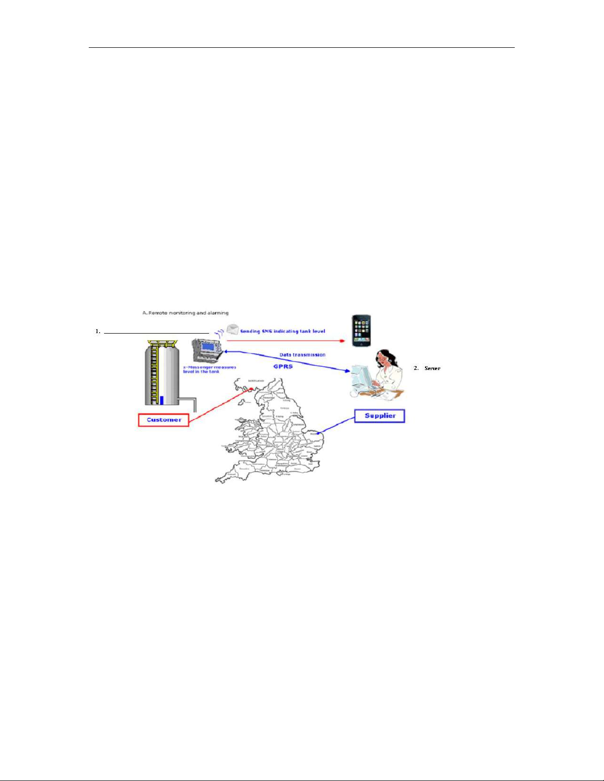
Application 3: Remote monitoring of product level in a tank

16
Application 4: Water Pressure Gauge, Fluid Gauge
Application 5: Data Centre, Power substation, Machinery plant unattended, Sites with expensive
equipment
Application 6: Freezer Warehouse, Walk-in Cold Room, Medical Storage, Data Centre, Power substation,

17
Laboratory
Application 7 Vending/Gaming Machine Monitoring & Reporting System
Application 8 Bridge Alarm System
Application 9 Farmland Sprinkler System

18
Chapter 3 Hardware models and resources
3.1 Naming Rules of EXM Series
EXM : series name
1. Points of total IOs
2. Power Supply ( DC 12~24V, AC 110~240V )
3. Digital/Analog( D :digital,DA : digital &analog configurable, DAI: digital,(0…10V)&(0/4…20mA))
4. Output type(R :Relay, TN : transistor(PNP type), RT: Relay and transistor)
5. Special function ( N :Ethernet access WIFI: With Wifi connectivity but no GSM/GPRS; GWIFI: With Wifi
connectivity and GSM/GPRS; V:Voice function)
3.2 Hardware model selection
x-Messenger (SMS Micro PLC) Model Selection chart (excluding extension and accessories)

19
Model
EXM-8AC-R-HMI
EXM-12DC-DA-R-HMI
EXM-12DC-DA-R-N-HMI
Supply Voltage
110~240VAC
DC 12-24V DC 12-24V
Inputs
6 digital
4 digital/analog+4 digital
4 digital/analog+4 digital
Analog Input signal
No
4 DC (0..10V)
4 DC (0..10V)
Outputs
High Speed Count(I7,I8)
2 relay(10A)
4 relay(10A) 4 relay(10A)
No
(I7,I8)60kHz (I7,I8)60kHz
SMS
Yes (64 different short message configuration)
GPRS
Yes
Ethernet
No
No
Yes
Data logging
Optional(Optional accessory: ELC-MEMORY required)
Interface
1 RS232(ELC-RS232 cable is required) & 1 RS485(RS485 module is required)
Communication protocol
Modbus RTU&ASCII
Modbus RTU&ASCII Modbus RTU /ASCII /TCP
RTC
Yes
LCD display with keypad
Yes
Alarming mode
SMS, Ring
output control mode
SMS , Call-In, Logic program control
Programming
Standard config soft& Customized soft(Function block diagram)
Email
Yes(can send email out)
Model
EXM-8DC-PT100-R-HMI
EXM-12DC-DAI-R-HMI
EXM-12DC-DA-R-VN-HMI
Supply Voltage
110~240VAC
DC 12-24V DC 12-24V
Inputs
2 digital
2 digital/analog+2 analog+4 digital
4 digital/analog+4 digital
Analog Input signal
2 PT100(-50--200℃)
2 DC (0..10V)+2(0/4...20mA)
4 DC (0..10V)
Outputs
High Speed Count(I7,I8)
4 relay(10A)
4 relay(10A) 4 relay(10A)
No
(I7,I8)60kHz (I7,I8)60kHz
SMS
Yes (64 different short message configuration)
GPRS
Yes
Ethernet
NoNoYes
Data logging
Optional(Optional accessory: ELC-MEMORY required)
Interface
1 RS232(ELC-RS232 cable is required) & 1 RS485(RS485 module is required)
Communication protocol
Modbus RTU&ASCII Modbus RTU&ASCII Modbus RTU /ASCII /TCP
RTC
Yes
LCD display with keypad
Yes
Alarming mode
SMS, Ring
output control mode
SMS , Call-In, Logic program control
Programming
Standard config soft& Customized soft(Function block diagram)
Email
Yes(can send email out)

20
Note: A. RS485 port can be used as either expansion or communication port, while serving as
Model
EXM-12DC-DA-RT-WIFI
EXM-12DC-DA-RT-GWIFI
Supply Voltage
DC 12-24V
DC 12-24V
Inputs
4 digital/analog+4 digital
Analog Input signal
4 DC (0..10V)
Outputs
High Speed Count(I7,I8)
2 relay(10A) +2 Transistor(0.3A)
(I7,I8)60kHz
SMS
No Yes (64 different short message configuration)
GPRS
No Yes
Wifi interface
Yes
Yes
Ethernet
Yes
Yes
Data logging
Optional(Optional accessory: ELC-MEMORY required)
Interface
1 RS232 & 1 RS485
Communication protocol
Modbus RTU&ASCII/TCP
Modbus RTU /ASCII /TCP
RTC
Yes
LCD display with keypad
Yes
Alarming mode
No SMS, Ring
output control mode
Logic program control SMS , Call-In, Logic program control
Programming
Standard config soft& Customized soft(Function block diagram)
EmailNoYes(can send email out)
communication port, EXM-E-RS485 communication module would be required as such port is not photo
electricity-isolated.
3.3 Resources
3.3.1 GSM /GPRS module built- in
Each x-Messenger CPU integrates an industry Quad-band GSM module inside. The x-Messenger can work
under the following GSM networks: 850MHz, 900MHz, 1800MHz, 1900MHz and will search these frequency
bands automatically.
Note: A. all the x-Messenger CPUs support the GSM function except the EXM-12DC-DA-RT-WIFI.

21
3.3.1.1 How to establish the connection between x-Messenger and PC via GPRS?
1. Internet Address Disposal
A. Here under is GPRS network connection’s sketch map:
x-Messenger CPU(EXM) shall work as client at Internet and PC shall act as SERVER . Meanwhile, Internet
service provider would automatically assign one dynamic IP address to SIM card inserted into the
x-Messenger CPU(EXM).
B. Prior to establishing GPRS connection, these two tasks listed at below shall be performed.
User must apply for one static IP address from their local internet service provider( Such static IP address
shall be unique on earth), in this case, after successful connection setup from Router to
Internet, such static IP address shall be automatically designated to user’s Router. User might consult their
local internet service provider for more detailed information. However, if one unique static IP address is
already available, please go to the next step.
22
2. LAN Address Disposal
User shall assign x-Messenger CPU’s communication port for GPRS to IP address of server PC. e.g. “5002” is
just x-Messenger CPU’s communication port for GPRS, and “5001” had been assigned to computer 1 as well,
further let’s suppose 192.168.0.119 is just IP address for server PC(computer1, in above sketch map), then
Port “5002” shall be assigned to 192.168.0.119 in Router’s configuration. In addition, the said
communication port refers to the one to be configured via eSmsConfig, furthermore, such configuration
would be downloaded to x-Messenger CPU.
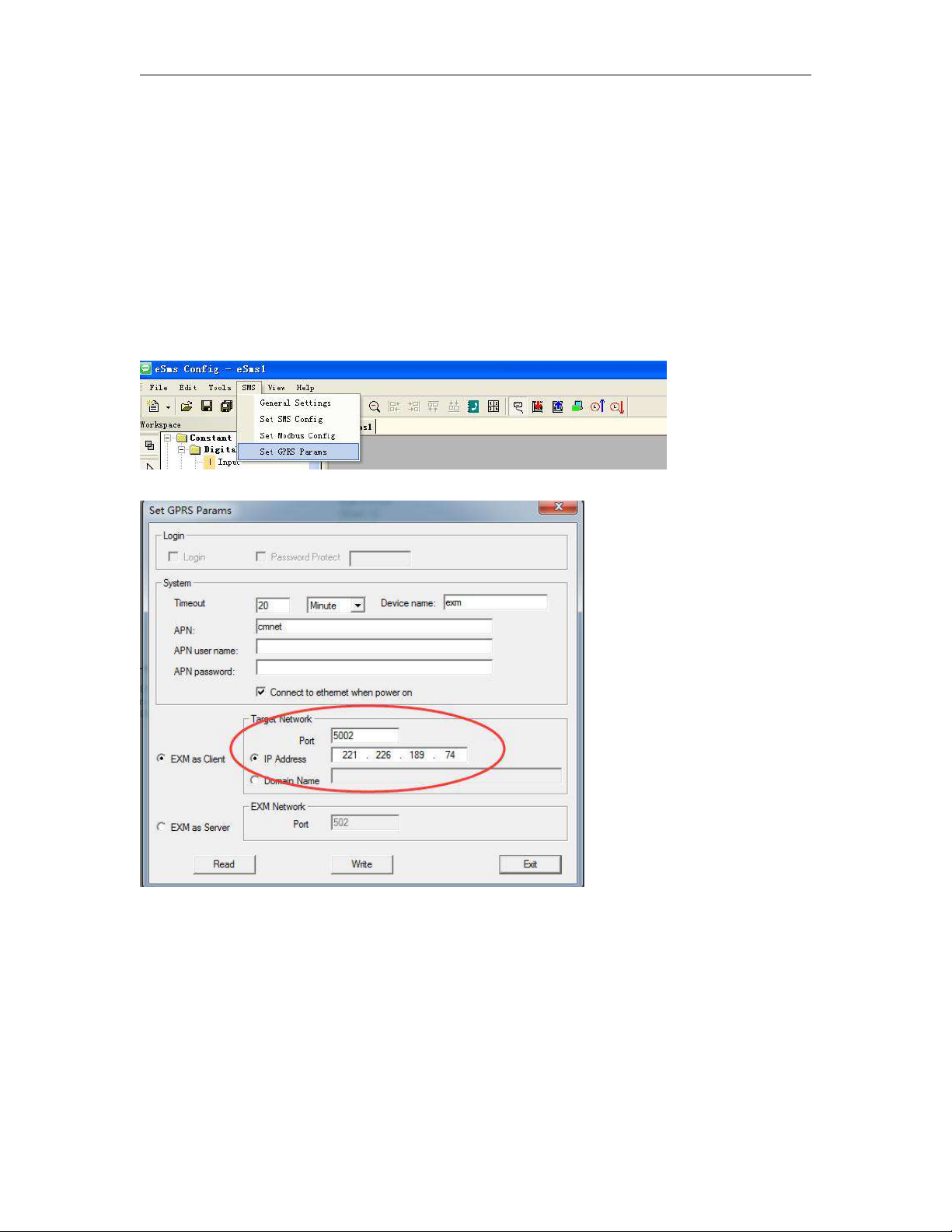
Click the menu “SMS->Set GPRS params” to set the server port number.
Please note that PORT’s assigning method is subject to various routers, hence, user shall consult your local
router suppliers for specific assigning method.
For instance, if the static IP address user had applied is 221.226.189.74, then such IP address shall be
treated as server address to be connected by all x-Messenger CPUs(EXM) involved in the network. Please

23
take a look at below demonstration configure as example for your better understanding.
C. Hereunder is a demonstration example illustrating GPRS connection establishment between remote
x-Messenger and eSmsConfig installed in the server PC(or other server software).
Step1: A static IP address shall be required, for example, it is 221.226.189.74, and you can refer to the
forementioned A&B for the detailed explanation on static IP address. Meanwhile, the eSmsConfig installed in
the server PC works as the server.
Step2: Open the software eSmsConfig and set up a connection between x-Messenger and eSmsConfig via
USB/RS232 mode.
Step3:To confirm the connection is established successfully, you can read the RTC from the x-Messenger.
Step4: Click the menu “SMS->Set GPRS params”.
Step5: Configure the APN based on your SIM card and then click "Write" to download the configuration into
x-Messenger.

24
Fig 3
You can set the IP address and the port number in the above dialog box. (It is based on your server(fixed
IP address).
Step6: Click the “ ” button. After set successfully, you can establish the connection via GPRS
between x-Messenger and eSmsConfig (your server).
Step7: Open the COM port again and select the GPRS option
Set the port number “5002” ( it is the same as the you set in the Fig 3), and click “Start server” and then
the IP address of x-Messenger will be displayed in the “EXM”. If you choose the “with Name” option, then
25
the device name and the IP address will displayed.
1.x-Messenger is client with a dynamic IP address,(SIM card)
2.Server software ( With a static IP address)
Step8: After the connection is established successfully, Program download/upload and data remote
monitoring can be realized in a wireless way all over the world.
Application:
Option A:
The server software can ask for some information such as temperature(analog inputs), level (digital inputs)
from the remote station, also it can remotely control items such as a valve with a standard command
(MODBUS TCP command). We are not supplying server software, which is available from other sources. This is
only to use the GPRS function.
The data transmission after the GPRS connection has been established, the communication protocol is
achieved using standard Modbus TCP. For the detailed information about the modbus protocol and memory
map/ register addresses of x-Messenger, please read the "Modbus TCP communication protocol" from our
side/website.
You can use our free of charge SCADA(easyScada) to communicate with EXM by GPRS(You can refer to the
SCADA user instruction about how to make the connection).
Option B:
x-Messenger can upload the digital inputs/outputs, analog inputs to the server(User can make their own
server software based on the modbus tcp protocol, or use our free of charge easyScada). There are 2 GPRS
function blocks available. Please see the chapter 7.2.14 &7.2.15 for a detailed description.

26
3.3.1.2 E-mail and how to set?
This chapter is only available under the customized programming mode!
Step A: Enable the GPRS function via the menu SMS->Set GPRS param.(The communication port must be
opened, and then this step would be available.)
Configure the APN(Access Point Name) based on your SIM card and then click "Write" to download the
configuration into x-Messenger.
When you want to send email out, the option “Connect to ethernet when power on” option is not important,
you can let it without ticked up.
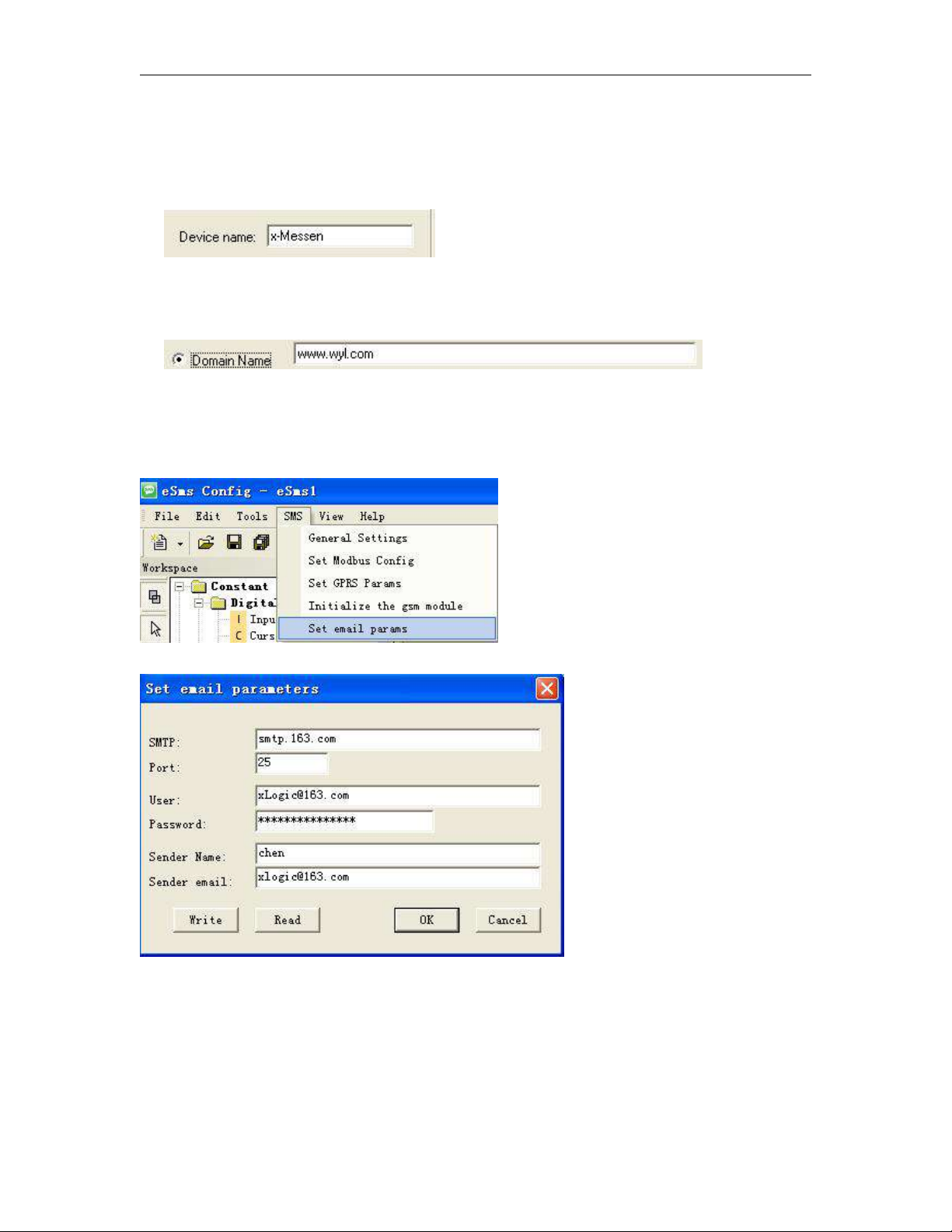
Step B: Set up your email parameters
Click menu SMS->Set email params

27
Click "Write" button to download the parameters into x-Messenger
The receiver email address and the alarm text can be edited in the "sms message output" function block.

28
1. Set the email address of the receivers, there are 3 receiver E-mail addresses can be set.
2. E-mail caption configuration box.
3. Email contents can be text message and parameters message
Text message can be edit in the message editor( 4 in the above figure)
Parameters message including such as IO status, analog IO values, kinds of parameters(counters, timers,
RTC etc).
3.3.1.3 How to change the register value(F,Q,AQ,AF,REG) or phonebook via SMS
Send an SMS message formatted like the example below
##**

29
AF1=2;
AQ02=100;
Q01=1;Q12=0;
F1=1;F2=0;
AM1=10;
REG1=100;
REG100=300;
TEL,B002,1,B002,2,B003,1,B003,5:13851448223;
RTC=89-01-09,01:32:09,0;
Message Parameters:
Start characters: ##** (These 4 characters must be included at the start of your message)
End character: ; (This symbol must be used to terminate each line of your message )
Parameters:
AF1= 2; This is to change the AF value, you can input the different numbers, for example AF=200;
AQ02=100; This is to change the AQ value, you can input the different analog outputs, for example
AQ21=200;
Q01=1;Q12=0; This is to change the the I/O output status, for example Q22=1;
F1=1;F2=0; This is to change the FLAG output status,for example F22=1;
AM1=10; This is to change the AM value, you can input the different numbers, for example AM30=200;
REG1=100;
REG100=300; This is to change the REG value, you can input the different numbers, for example
REG2=200; This can be used to change the current value of function blocks, such as counters.
TEL,B002,1:13851448223;
This is to change receiver for the sms message output block.
(Note: This command is only for 2G version unit, it is unavailable for 4G version unit)

30
If you send the short message contents as the
##**
TEL,B002,1,B002,2,B003,1,B003,5:13851428396;
,consequently, the receiver1 & receiver2 of the B002 function block and receiver1 & receiver5 of B003 shall
turn to 13851428396.
(Note: This command is only for 2G version unit, it is unavailable for 4G version unit)

31
How to modify the all the receiver number of sms message output blocks in the program ?
If you want to modify the receiver number in all the sms message output block, you can edit the short
message format like this:
##**
ALL:TELQ,1:13851448223;
This is to change receiver 1 for all the sms message output block in the program.
TELQ, means the “SMS message output block”
1 means the receiver 1 in the block, this number can be 1 to 5.
13851448223; It is the phone number which will be set into the receiver.
(Note: This command is only for 2G version unit, it is unavailable for 4G version unit)
Modify the telephone number in the sms message input like this:
Edit short message :
##**
Msg,I01,1,I01,2,I01,3,I01,4,I01,5,I02,1,I02,5,I03,2,I03,4,I03,5:10987654321;
And then the phone number in the sms message input shall be changed with 10987654321.

32
(Note: This command is only for 2G version unit, it is unavailable for 4G version unit)
MsgI01:
MsgI02:

33
MsgI03:
How to modify the all the receiver number of sms message input blocks in the program ?
If you want to modify the receiver number in all the sms message input block, you can edit the short
message format like this:
##**
ALL:TELI,1:13851448223;
(Note: This command is only for 2G version unit, it is unavailable for 4G version unit)
This is to change receiver 1 for all the sms message input block in the program.
TELI, means the “SMS message input block”
1 means the receiver 1 in the block, this number can be 1 to 5.
13851448223; It is the phone number which will be set into the receiver.

34
RTC=89-01-09,01:32:09,0;
This is used to change the Real time clock of x-Messenger, Year-month-day,hour:minute:second,week;
0: Sunday
1: Monday…..
Note: The parameters can include one or more items as above shows, for example, you want to modify
the phone number, you only need to edit message as follows:
##**
Msg,I01,1,I01,2,I01,3,I01,4,I01,5,I02,1,I02,5,I03,2,I03,4,I03,5:10987654321;
(Note: This command is only for 2G version unit, it is unavailable for 4G version unit)
This function also can be used between two individual x-Messengers CPU.
For example:
GMS
Locally Remote
The Analog input1 & Analog input2 of remote station can be sent to the local one by means of SMS.
The SMS message can be configured like this:
This parameter can be configured in the sms message output block.

35
How to change the phone book(include phone number and Email address)?(Only for 4G version)

36
When you download program, the xlogic will ask you if wish download the phonebook with program, you
need select yes, if the phone book is already changed!

37
Then we can edit below SMS contents to change the phonebook user1 phone number to “123456789”.
##**PB,cnf,1234∶123456789;
##** Start characters;
PB it means phonebook(includes the phone number and email address)
cnf the user name you used(if you use andy in the phone number, here you need edit with andy)
1234 this is password when you want to change the phone number(if you did not set it in the phone
book, here you can keep it blank or any other characters).
123456789 the phone number which will be set to replace the old one.
; End symbol
You can send above message to change the phone book, and if it is changed successfully or failed, the
EXM will do response with message.
The phonebook will be changed as below, and the phone number in the sms message input and output
block will be changed as well.

38

39
3.3.1.4 How to modify the PIN via SMS
Note: 1.The PIN code of SIM card must be set on cell-phone, here PIN is only for the x-Messenger.
2.Only when the PIN you set into x-Messenger is the same as the one of SIM CARD, and then the SIM
CARD would be in service in normal.
The PIN of x-Messenger can be set in the eSmsConfig from the menu “SMS->General Settings”

40
Send an SMS message formatted like the example below
1. GPRS parameters and modification via SMS.
##**
PIN:1234;
Message Parameters:
Start characters: ##** (These 4 characters must be included at the start of your message)
End character: ; (This symbol must be used to terminate each line of your message )
Parameters:
PIN:1234;
PIN code must be 4 digit Arabic numerals(0--9).
3.3.1.5 How to modify the GPRS Parameters and Email parameters via SMS
GPRS parameters can be viewed from menu “SMS-> Set SMS parameters”

41
Send an SMS message formatted like the example below
##**
PGPRS:
TIMEOUT"60",
IPORDOMAIN"0",
POWCONNECT"0",
APN"CMNET",
TADR"221.226.189.74",
TPORT"5005",
SNUMB"12345678",
DOMAIN"www.wyl.com";
Message Parameters:
Start characters: ##** (These 4 characters must be included at the start of your message)
Parameters interval characters: , (This symbol must be used to differentiate each parameter of your
message )
End character: ; (This symbol must be used to terminate each line of your message )
Parameters:
PGPRS : (This head means the below contents is used to modify the GPRS parameters)
TIMEOUT"60", (This is to change the time out period, the unit is “second” and the minimum value is
30, if you set the value less than 30, x-Messenger would set 30 automatic value)

42
IPORDOMAIN"0", This is to change network mode. IPORDOMAIN"0", means IP address option shall
be ticked:
And if IPORDOMAIN"1", means Domain Name option shall be ticked.
POWCONNECT"0", This command is used to change the option “Connect to ethernet when power on”,
if the contents is POWCONNECT"0", this option shall be un-ticked:
And if the contents is POWCONNECT"1", this option shall be ticked:
APN"CMNET", This command is used to modify the APN(Access Point Name).
TADR"221.226.189.74", This command is used to modify the Target IP address
TPORT"5005", This command is used to modify the Port number for target network.
43
SNUMB"12345678", This command is used to modify the Device Name(serial number) 8 characters in
2.Email parameters and modifications via SMS.
maximum.
DOMAIN"www.wyl.com"; This command is used to modify the Domain name.
Email parameters can be viewed from menu “SMS-> Set email params”
Send an SMS message formatted like the example below
##**
PEMAIL:
SMTPADR"smtp.163.com",

44
SMTPPORT"25",
SMTPUSER"xLogic@163.com",
SMTPPWD"12345678",
SENDNAME"chen",
SENDEMAIL"xLogic@163.com";
Message Parameters:
Start characters: ##** (These 4 characters must be included at the start of your message)
Parameters interval characters: , (This symbol must be used to differentiate each parameter of your
message )
End character: ; (This symbol must be used to terminate each line of your message )
Parameters:
PEMAIL : (This head means the below contents is used to modify the email parameters)
SMTPADR"smtp.163.com", This command is used to modify the SMTP for your Email box
SMTPPORT"25", This command is used to modify the SMTP for your Email box.
SMTPUSER"xLogic@163.com",This command is used to modify the user name for your Email box.
SMTPPWD"12345678",This command is used to modify the password for your Email box.
SENDNAME"chen",This command is used to modify the sender name for the Email.
SENDEMAIL"xLogic@163.com";This command is used to modify the email address for the sender..
You are allowed to send a SMS to check the settings as follows:

45
##**
RPGPRS;
RPEMAIL;
Parameters
RPGPRS; This command is used to check the settings of GPRS. GPRS information would be sent to the user
who want to check.
RPEMAIL; This command is used to check the settings of GPRS. GPRS information would be sent to the user
who want to check.
3.3.1.6 How to modify the email address of the receiver via SMS?
Note: this chapter only for 2G version unit, not available for 4G version, you need change the phone book(Refer to
chapter 3.3.1.3 about how to change phone book).
Send an SMS message formatted like the example below
##**
EML,B002,1,B002,2,B003,1,B003,3:xLogic@163.com;
Message Parameters:
Start characters: ##** (These 4 characters must be included at the start of your message)
End character: ; (This symbol must be used to terminate each line of your message )
Parameters:
EML,B002,1,B002,2,B003,1,B003,3:xLogic@163.com; The receiver 1, receiver2 of B002
block and receiver1, receiver3 of B003 block would be modified to “xLogic@163.com”.
B002(Sms Message Output):

46
B003(Sms Message Output):
How to modify the all the receiver E-mail address of sms message output blocks in the program ?
If you want to modify the receiver E-mail address in all the sms message input block, you can edit the
short message format like this:
##**
ALL:EMALQ,1:xLogic@163.com;
47
This is to change receiver 1 for all the sms message output block in the program.
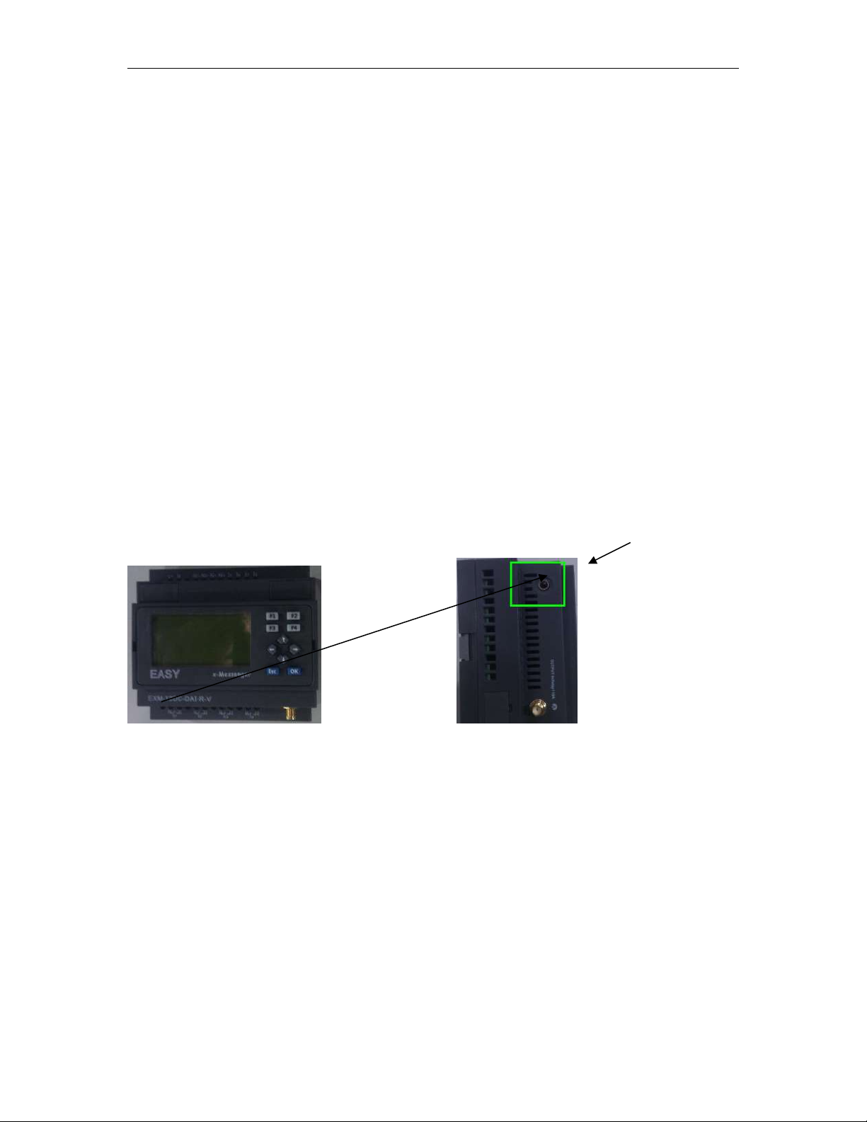
A.Voice module on-line recording audio input port &Audio output port (to be connected with the microphone
EMALQ, means the the receiver email address in the sms message output block.
1 means the receiver 1 in the block, this number can be 1 to 3.
xLogic@163.com; It is the phone number which will be set into the receiver.
3.3.2 Voice alarm
With '-v" series x-Messenger CPU means the voice function is available. Voice function includes voice alarm,
telephone control function and automatic dialing function. Voice alarm can be realized via the audio jack (see A
below) or the built in speaker in certain models (see B below), alarm message also can be got after you hold the call
from x-Messenger and press the button on your phone according the prompt voice. Telephone control
function means you can control the x-Messenger with your phone remotely.
Structure of the voice interface
A
With HMI model(-v)
(Input) or speaker (Output)) Applied to both with HMI model and without HMI model.
How to record the voice section into x-Messenger?
Before recording, equip your PC with voice card , otherwise the recording can’t be carried out.

48
Step A.
Establish the connection between x-Messenger programming port and the COM port of your PC(RS232/USB)
with the download cable(ELC-USB,ELC-RS232, EXM-USB-B ) and the connection between the audio input
interface of x-Messenger and the audio output interface of your PC with audio wire(see below figure).
Free audio wire accessory, to connect the voice audio input and PC audio output.
Step B. Open the "eSmsConfig" software and establish the communication (Select the correct com port you
are using, and connect to EXM).

49
Step C. Download voice section.
Click menu Tool-> Record
Click "Hardware Detect" button.

50
1. Sound format selection:
There are 3 options : 4m ,6m and 8m.
2. Voice section displayed, you can add ,delete,and clear all the file with the relevant button. The voice file
3. Erase the voice section in x-Messenger.
4. Record all the voice section by click "Start".( While the "Start button" is pressed down, the voice would be
6. File progress: It is showing you the voice section "playing progress".
7. Memory progress: It is showing you the voice memory space status. Total memory space can be used
In total length range of the recording, the recording of the voice module can be divided into 0-99 sections .
(Note: Option1: 4 minutes, the voice sampling frequency is 3.4 K Hz, Option2: 6 minutes, sampling
frequency is 2.3 KH z, 8 minutes sampling frequency is 1.7KHz, if you want better sound quality, use a higher
sampling frequency. )
format is ".wav" Any other format file is unavailable.
Erase all the voice sections by clicking the "Erase all" button.
Erase one of the voice section by clicking the "Erase one" button. You can input the voice section number
in the dialog box which you want to delete.
played and at the same time x-Messenger shall record one by one.)
Note: The audio wire must be connected between x-Messenger and PC, otherwise , although the voice has
been displayed, x-Messenger cannot record any voice section. In other words, the voice section is
downloaded from PC to x-Messenger by the audio wire, not via the download cable.
to store up to 4, 6 or 8 minutes voice section.
Note: 4 minutes format with the best voice quality, and 8 minutes format with the worst voice quality.
8.Hardware play: You can play any one of the voice sections in the x-Messenger(0-99 section)

51
Relative voice function block description
Connection
Description
Input En
You enable/disable the sound play with the signal at input En.
Output Q
Q switches on if sound play were enabled and the sound section had been played
more than 1 time successfully.
A. Interior speaker
Sound play
Description of function
The relative voice message would be played if this block were enabled. There are 3 optional ways for sound
playing:A. built-in speaker B. External speaker C. Phone alarm voice
Property dialog box description
This option is for the built-in speaker model.(Only applied to "....-v-cap" model, this type is discontinued)

52
B.External Speaker
External acoustics
Sound message :
Voice section selection.
Sound message: 0 means the voice section 0 from the record manage dialog box.

53
Voice alarming via phone
In your program, you must use the "sms message output'' function block(Refer to the relative chapter in the
user manual).
Select the "Sms Dial" option, you can choose the receiver phone number from the Phone book. If this block
were enabled, x-Messenger would dial to the corresponding user's cell phone. And users can check the alarm
voice according to the broadcast contents.If there is no "sound play" function block enabled, x-Messenger
would not broadcast alarm voice section.
How to realize the 'telephone control function' ?
When a user dials x-Messenger, x-Messenger will answer the telephone automatically and broadcast-Please
enter the password for confirmation, then the user enters the x-Messenger password.
A. If the entered password is correct, x-Messenger will then broadcast-Correct password. Please enter
the control code to control. Then the user can control the equipment by the use of the telephone key.
Note: This function is available only if you put the sms message input function block in your programme and
select the "Incoming Call and Answer call" box.

54
Telephone key
Description of function
There are 9 bit flags based on the 1--9 key of the telephone. After you enter into the telephone control mode,
and enter # 0, the P0 block would give off one trigger. If you enter # 8, the P8 would give one trigger
Operation Instructions of the Voice function for x-Messenger
1.The first five sections (section 0, section 1, section 2, section 3, section 4) are for
the voice system. Users cannot record the five sections randomly.
2.Section 5 to section 99 of the voice module are the voice sections for users
programming and can be used randomly. However, users must start recording from
section 0 while the functions of section 0 to section 4 are fixed by the system.
Functions from section 0 to section 4 are as follows:
Section 0: When dialing out through the “sms message input/output” block, it will broadcast this section
“Please enter No. 0 key and receive the information”. (When recording, users must record this voice
contents “Please enter No. 0 key and receive the information”)
Section 1: the voice prompt for confirming the user status. It will be broadcasted
when x-Messenger system number has been dialed or x-Messenger dialed out to configured user. Normal
broadcasting can be carried out with this section.
Section 2: the voice prompt for the correct password. It will be broadcasted when the
correct password is used. Normal broadcasting can be carried out with this section.

55
Section 3: the voice prompt for the wrong password. It will be broadcasted when the
1. x-Messenger dialing an external telephone, if there is no answer or a password is not entered within the
wrong password is used. Normal broadcasting can be carried out with this section.
Section 4: the voice prompt for dialing to an external telephone. It will be broadcasted
when x-Messenger dials an external telephone. Normal broadcasting can be carried out with this section.
3.Usage of the five special sections
For example: users can use the five message sections as follows:
Step I:
Record section 0 as Please enter No. 0 key and receive the information.
Record section 1 as Please enter the password for confirmation.
Record section 2 as Correct password. Please enter the control code to control.
Record section 3 as Wrong password. Please re-enter.
Record section 4 as Emergency. Please enter the password to control.
Record section 5 as Emergency. Gas leakage.
Step II:
When a user dials x-Messenger, x-Messenger will answer the telephone automatically and broadcast-Please
enter the password for confirmation, then the user enters the x-Messenger password.
A. If the entered password is correct, x-Messenger will then broadcast-Correct password.
Please enter the control code to control. Then the user can control the equipment
by the use of the telephone.
B.If the entered password is not correct, the x-Messenger will broadcast-Wrong password.
Please re-enter. Then the system will repeatedly broadcast-Please enter the
password for confirmation.
Step III:
When x-Messenger dials an external telephone number(pre-set in sms message output block of your
program), it will broadcast the pre-set message such as section 5-Emergency, Gas leakage. Together with
section 4-Emergency, Please enter the password to control.
A. When the user enters the correct password, the voice system will broadcast
section 2-Correct password. Please enter the control code to control and then
repeatedly broadcast section 5-Emergency, Gas leakage. At this time the user can
take control of connected equipment in real time by the use of the telephone.
B.When the user enters a wrong password, the voice system will broadcast section
3-Wrong password. Please re-enter. And then it will broadcast section 4 and section
5 repeatedly.
Password protection is according to the x-Messenger settings, if there is no password for x-Messenger, it will
broadcast the alarm voice without section 2.
Notes:

56
connection set point time, the x-Messenger voice system will stop dialing and cease to broadcast the voice
message. The x-Messenger will then redial automatically according to the settings in the "Sms message
output block.
2. User must enter a # before entering the password. The broadcasting will then stop
and the user should enter a four-digit password within 10 seconds. If the user fails to
enter the password, the x-Messenger will re-broadcast the voice prompt. The user
must then enter # first and then enter the password. If the user needs to enter the
password again, the procedure needs to be repeated. That is to say that every time
the user needs to enter the password, he must enter a # first and enter a four-digit password
within 10 seconds after the voice has stopped.
3. When the user has entered the correct password, the voice system will broadcast
section 2-Correct password. Please enter the control code to control and then
the user can do the following operation. If the password is wrong, the voice system
will broadcast section 3-Wrong password. Please re-enter. The user can only enter
the wrong password three times. If the user enters the wrong password for a fourth time , x-Messenger will
hang up the telephone and stop broadcasting. If the alarm status still exists, the voice system will dial
automatically, for alarm purposes, every 40 seconds.
4. When the alarm status exists, x-Messenger will broadcast the alarm voice
repeatedly. It can be stopped by the use of the control function within the program.
5.
For the first time set-up, before recording, the user must delete existing messages before. Otherwise the recorded voice
may be lost. As to the recorded voice messages, user may delete or modify randomly the voice message in
them. And it has no effect on the other voice messages. As for the details, it is explained in the voice
recording
explanation.

57
Examples of Voice Module
3.Set the telephone.
Preparations:
1.Connect the x-Messenger to your PC as detailed above.
2.Record message. (The first five messages must be recorded and the other four messages recorded according to
the user's needs.)
Message 0: Press key #0 and listen to the message.
Message 1: Please enter the password.
Message 2: Correct password.
Message 3: Wrong password. Please re-enter.
Message 4: Run normal. No alarming.
Message 5: The door is not closed. Please handle urgently.
Message 6: Thief. Please catch. Address: No. 28, ningshuang Road.
First you need edit the phone book and select the phone number in the sms message input/output.
Second:
SIM card in x-Messenger is No.1234567
Set the user1 phone No. 11111111
Set the user2 phone No. 22222222
Set the user3 phone No. 33333333
Set the user4 phone No. 44444444
Example 1
Check if x-Messenger system running normally and retrieve unit information. The user himself check the system,
the password is set. Only the password is correct, the system information can be learned. So set the
password via the panel key or software.

58
When programming, requirements are as follows:
① Correct password.
② Set related function block.
Program is as follows:
MsgI01 "sms message input' function block property box settings:
x-Messenger can only answer a call from user1,user2,user3,user4 phone number, other users calls cannot be
answered.
B001 "Sound play" function block property settings

59
Actual Demonstration:
① Dial the telephone No. 1234567 of the voice module from user1--4..
② It will play Message 1 “Please enter the password.”
③ Enter the preset password via the telephone keys.
A. Correct password.
It will play Message 2 “Correct password.” If I1 is not triggered, it will play
Message 4 “Run normally. No alarm.” After playing, if user doesn’t hang up the
telephone, it will play Message 4 repeatedly.
B. Wrong password.
It will play Message 3 “Wrong password. Please re-enter.” and then Message 1
“Please enter the password.”
Example 2
x-Messenger system detects there is something abnormal and prompt the user. Under this situation, the
x-Messenger is needed to set password to avoid the stranger knowing the prompting contents. Password
can be set via the panel key or via the menu in eSmsConfig software.
Program is as follows:

60
B002 "sms message output' function block settings:
Actual Demonstration:
① x-Messenger system detects that the door is not closed. (I1 connected to the switch testing the door
status.) I1 is triggered and B002 is activated by I1. Then the x-Messenger will dial user1 11111111 the preset
telephone of B002.
② When the user picks up the telephone, he will hear that “Please press Key #0 and
listen to the message.”
When the user presses Key #0, it will play Message 1 “Please enter the password.”

61
In this example, when the voice module dials the preset telephone, if the user1 doesn’t
pick up the telephone, x-Messenger would dial user2 and user3 according to the confirmation
settings(waiting time and loops)
3.3 Ethernet module with built-in webserver
There are 2 different Ethernet configuration method for old and new series Ethernet CPU. For the new one,
you can refer to chapter 3.3.1--3.3.6. For the old one, please refer to chapter 3.3.7
3.3.1 How to separate the new version and old version?
New functions for Ethernet PLC from Rievtech is released.
Included CPU models:
ELC-12DC-DA-R-N
EXM-12DC-DA-R-N(-4G)
Method A:
Label on the bottom of the plastic house of the CPU. The new version marked with “V2” following the model.
Method B:
Get the version number by the software menu Tools-> transfer-> Get PLC version
If the hardware version is 1, that means it is new version.
Difference between 2 versions:

62
Items
New version
Old version
Network parameters
configuration software
Program software(xlogicsoft or
eSmsconfig)
The menu is Transfer-> Web
server config
DeviceManager software
TCP Server/client
Work as TCP server or clients at
the same time.
Only one mode can be applied
( tcp server or
Tcp client)
TCP Connections.
Max separate tcp
connections(Tcp server+Tcp
clients) :8
Works as Tcp client: Can connect
1 Tcp server.
Works as TCP
Built-in Web
server(Control&Software)
Yes
No.
3.3.2 How to Configure the Network parameters through program software?
For EXM-12-N , you can use eSMSConfig to configure the Ethernet network parameters through the menu
Tools-> transfer-> web server config
1. Local CPU Network settings
IP Address
Subnet Mask

63
Default Gateway
Web Port
MAC Address
Protocol
The option: Enable web Server
2.TCP server
Port : This port is for TCP server. Keep alive: (This settings is no used)
Max Clients:
Total TCP connection numbers is 8, so you can set all the connections for clients, if you set 8, then the PLC
cannot work as TCP server anymore.
Timeout: 0s means, it will not be timeout, the server will always on-line even if there is no data transferred.
If the value is not 0, that means if there is no data transmission, the connection will restart.
3.Target
If you select max 0 clients in the 2 item(tcp server), then all the 8 target server IP address and port number
will be available.
You need tick up the “enable” option and input the remote server ip address and port number.
Keep alive: if there is no data transmission, the CPU will send a package without data to the server to make
sure it still is on-line.
Type: TCP or UDP optional
Timeout: 0s means, it will not be timeout, the connection will always be kept even if there is no data
transferred. If the value is not 0, that means if there is no data transmission when the timeout, the connection
will restart.
4.UDP server
The CPU can work under UDP server as well, you can tickup the enable option.
After you finished the parameters configuration, you need download the settings into the CPU by serial
connection or Ethernet Connection like download the program. And at last you need click the “Confirm and
Reset” button, then the CPU will restart and the new settings will be available.
Detailed method:
A.Create the connection between PC and the CPU by serial cable(RS232/USB cable) or Ethernet(You can
check the CPU IP address and server port number on the LCD menu).
Connect the CPU with PC through the USB cable: Click the open com port option, and select the COM port of
the USB cable, here the port number is COM3, then click the button “connect to PLC”.

64
If you has no USB cable there, you can use the Ethernet connection.
First check the PLC address with LCD menu
Get the IP address from:
>Network -> IP Config.. -> Local IP ADDR.. -> Local IP (192.168.0.201)
Get the TCP server port from:
>Network -> IP Config.. -> TCP Server.. -> TCP Server Port (6400).
Then you can use the Ethernet option(PC as Client) to connect with CPU.
IP:192.168.0.245
Port:8008

65
After the connection is created, you can click get the clock icon to confirm the communication is ok.
Now you can configure the Network parameter by the menu Tools-> transfer->Web server Config

66
You can read the parameters from the PLC.

67
3.3.3 How to view and configure the Ethernet parameters through LCD panel?
You can view and modify the network parameter through the LCD menu.

68

69
You can modify the Local IP address, subnet mask, gateway from the LCD menu :
Web server port also can be modified and the web server also can be disabled or enabled:
You can view the MAC address from here, but it cannot be modified:
TCP server port settings and allowed tcp clients settings:
View and modify the UDP server from here:
Set the Target server IP address and port number:

70
You can make the IP settings to factory by the menu
“RST IP Config”, the IP address will return to 192.168.0.201, and the tcp server port number will be 6400.
“RST Log on” the webserver log on name and password will be back to “admin”.
Modify the IP address:
Press ok to enter into the modification mode, the cursor will flash at the address position. The you can move
the cursor by Left or Right button, and change the value by pressing UP/DOWN button.
At last confirm with ok.
After you confirm the parameters with the ok button, the settings are not enabled , only after the CPU restart,
the settings will be enabled? So when you leave the settings the LCD will show you:

71
You need select “Yes” and press ok, the the CPU will restart, now the new settings will be available.
3.3.4 How to create the communication between the CPU and PC through Ethernet?
To communicate with the CPU, you can use the TCP/IP protocol. The CPU can work as TCP server and TCP
client at the same time, and also it can work as UDP server or UDP Client as well.
Notes:
1.The Ethernet can work under TCP and UDP mode, you can create the connection between our Ethernet
CPUs, and also you can use our Ethernet CPU to create the connection with other factory Ethernet device
based on TCP or UDP.
2.The communication protocol through Ethernet is MODBUS TCP or MODBUS RTU of our PLC, so if you want
to communicate with other factory device through Ethernet, you need make sure the device also supports
MODBUS TCP. Or MODBUS RTU.
3.Our Ethernet PLC(built-in webserver version) can work either as master or slave.
CPU works as TCP server
The maximum TCP connection is 8, so one CPU allow maximum 8 TCP clients to connect with the CPU at the
same time. And each TCP connection is totally separately.
For example:

72
All the 8 clients can monitor and control the CPU at the same time.
Com with xlogicsoft(PC is client)
First check the PLC IP address with LCD menu
Get the IP address from:
>Network -> IP Config.. -> Local IP ADDR.. -> Local IP (192.168.0.146)

73
After the connection is established, you can download/upload the program and monitor the program like the
usb cable connection.

74
Com with easySCADA(PC is client)
You need set the correct IP address and com port in the device configure of the easySCADA.
Our xLogicApp(Smart phone is tcp client)
Interface configure

75
Modbus Poll works as TCP client

76
CPU works as TCP Client
The maximum TCP connection is 8, so one CPU allow maximum 8 TCP clients to connect with the CPU at the
same time. And each TCP connection is totally separately.
For example:
All the 8 Servers can connected, and the data transmission can be processed separately.

77
If we set Max clients 0, then the CPU will only play as tcp clients, then there are 8 tcp servers can be
connected at the same time.
Xlogicsoft works as TCP server and wait the CPU log on(The PC IP address is 192.168.0.227):

78
TCP Sever 192.168.0.227, port:8004 is ok.
TCP Sever 192.168.0.227, port:8005 is ok.

79
TCP Sever 192.168.0.227, port:8006 is ok.
TCP Sever 192.168.0.227, port:8007 is ok.

80
TCP Sever 192.168.0.227, port:8008 is ok.
TCP Sever 192.168.0.227, port:8009 is ok.

81
CPU works as UDP Server
CPU can work as UDP server, you can use your software to connect with it through UDP or make several CPUs
communication through UDP as well.
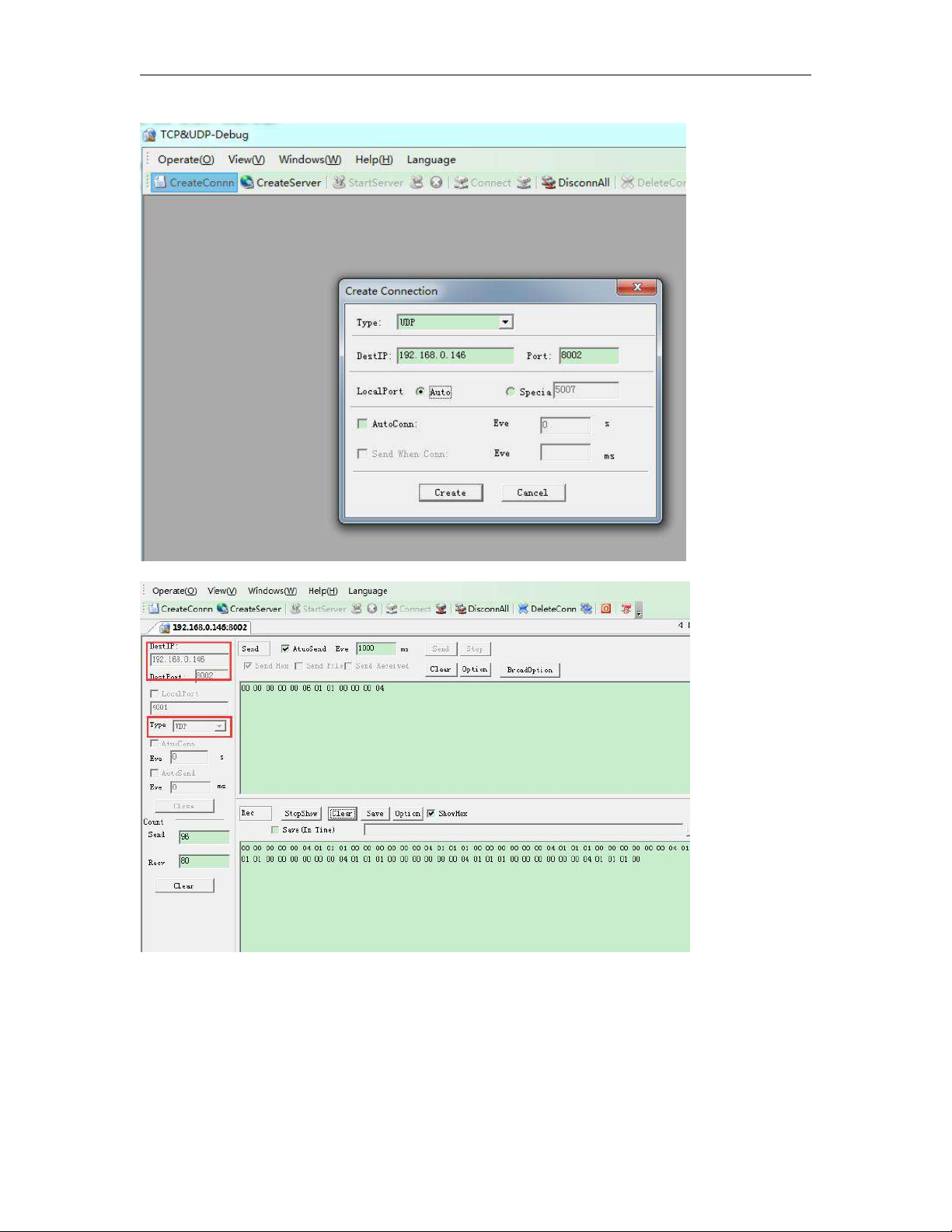
82
After the connection is created, the CPU and the software can communicate based on MODBUS TCP protocol.
3.3.5 How to log on the built-in Web server

83
Only the new series ELC-12DC-DA-R-N has built-in web server. So you can use PC or
mobile phone to control PLC.
Supported browser
·Chrome
·IE
·Please ensure that your browser is the latest version.
Supported devices
·PC
·iPhone
·iPad
·Android mobile phone
·Android pad
Supported language
·English
·Chinese
·Deutsch
·Francais
·Italiano
·Espanol
How to enable the webserver?
(1)Open Xlogic software,choose ELC-12DC-DA-R-N model and connect xlogicsoft to PLC,you can use serial
port or network port to connect PLC.
(2)Tools-->Transfer-->Web Server Config

84
(3)Click Read button to read web server configure.
The default configuration is as follows:

85
The webserver is enabled in default, if you want to disable the webserver access, you just only cancel the
option “Enable webserver” then the webserver would be not allowed to access.
How to log on the webserver?
1.You have to get IP address of PLC,then input IP address of PLC to the
browser,Web server interface will appear.The default IP of PLC is 192.168.0.245, the Default port of PLC is
8008.So you can use the default IP address to log on web server,you can also use the IP and port of PLC to
connect the xlogic software to the PLC and configure web server parameters.
If you have changed the IP address, you can view the IP address by the LCD menu
>Network -> IP Config.. -> Local IP ADDR.. -> Local IP
2.Open the browser,then input the IP address of PLC(Input your PLC IP address).
3.Press “Enter” key,the following interface will appear.
4. Log on interface
Name:The default name is admin.
Password:The default password is admin.

86
Language:Our web server supports six kinds of languages.You can choose your language.
Keep me logged on:When you choose “Keep me logged on” ,then you click on“Log on” and you log on to the
web server successfully.You will always stay in the login state.If you close the browser,then you open the
browser again,input the IP address ,you will still stay in the login status.You can click on the “Log off”to exit
the login status.
Log on:Click on it,log on to the web server.
Check CPU information
After logging on to the web server,web server will display the information of CPU.
CPU name:
Display CPU name.
Current status:
Display the status of PLC
CPU clock:
When you click on the “ CPU information”,“CPU clock” will display the current time of PLC.Select the “ PC
synchronized”,then click on “Set”,the PC time will be written in PLC.
CPU Addr:
Display CPU address.You can change the address of PLC.
Example:
You can input “5” ,then click on“Set”,the CPU address will be 5.
CPU model:

87
Display CPU model.
Firmware Ver:
Display Firmware Version.
Hardware Ver:
Display Hardware Version.
GPRS connection: (For EXM series CPU)
Display “connected” or “Not connected”.
GSM signal:(For EXM series CPU)
Display GSM signal.
Variable Configure
“Variable config” interface
You can click on “Add Variable” to add variable. And you can change or delete the variable as well.
Up to 16 variables can be configured
Name:
You can define a name for variable.(8 characters can be input)
Item:
You can configure 13 kinds of variables.(These variables are in the xlogicsoft)

88
Address
Type:
Data length of variable.Include: BIT,WORD,DWORD.If you use timer or counter,you should choose TIMER or
COUNTER.
Display Format:
Display format, include: BOOL,SIGNEO, UNSIGNED,HEX,BINARY.
DEL:
Click on to delete variables .
Save Variable:
After finished configuration variables,you have to click on“Save Variable”,then you can monitor and control
variables at “Monitor&Control”.
Monitor&Control
On this page,you can monitor and control variables. Web server refreshes data automatically.
Auto refresh:choose “Auto read interval”and choose refresh time.

89
The web server refreshes the current value of variables every 0.3s-5s.The default auto refresh time is 1
second.
Name:
Display the name of variable.
Address:
Display the address of variable.
Status/Value:
Display the current status or value of variables.
Change:
Change the current status of variable.When you change the current
Status:
status of variable,you have to click on the corresponding “Set” button.
Description of changing the state of variable
Variable I:
You can’t change the status of variable I.
Variable Q:

90
When the input pin of output block Q is not connected,you can change the status of variable Q.
If the input pin of output block Q is already connected with other blocks,you can’ t change the status of
variable Q anymore.
Variable AI:
You can’t change the value of variable AI.
Variable AQ:
When the input pin of analog output block AQ is not connected,you can change the value of variable AQ.
If the input pin of analog output block AQ is already connected with other blocks,you can’t change the value
of variable AQ anymore.
Variable F:
When the input pin of digital flag variable F is not connected,you can change the status of variable F.
If the input pin of digital flag block F is already connected with other blocks,you can’t change the status of
variable F anymore.
Variable AF:
When the input pin of analog flag block AF is not connected,you can change the value of variable AF
If the input pin of analog flag block AF is already connected with other blocks,you can’t change the value of
variable AF anymore.

91
Variable HEG:
Cannot be set, only can be read.
Variable M:
You can’t change the status of variable M, it only can be read.
Variable AM:
You can’t change the value of variable AM, it only can be read.
Cursor key:
You can’t change the status of cursor key, it only can be read.

92
Panel key:
You can’t change the status of panel key, it only can be read.
Shift register bit:
You can’t change the status of shift register bit, it only can be read.
User Management
User management interface
You can set a new user name and new password at this page. If you have set a new user name and
password,the old user name and password can’t be used.A web server just has a user name and a password.
If you forgot the user name or password you logged, you can reset it by the LCD menu
You can make the IP settings to factory by the menu Network-> IP Config..-> Factory-> RST Log on

93
After you reset the log on, the user name and password will be back to the default “admin”.
RIEVTECH On-line
RIEVTECH On-line Interface
You can monitor and operate the LCD panel remotely.
The CPU only can get a trigger from the virtual keys, it cannot get a continuous signal, that means if you press
the OK key for 3 seconds, the CPU cannot know it pressed down 3 seconds, it only get a trigger signal.
So if you want to realize the press ok key for 3 seconds to change the parameters in the text message on the
hardware, you need press the “set” key on the virtual panel.
Press “Set” = Press ok key for 3 seconds when there parameters in the text message need be modified!

94
3.3.6 How to establish the communication between new Ethernet CPUs?
We can make the Ethernet connection based on the TCP connection or UDP connection. We can see the
communication with 2 steps operation.
Step 1: Configure and create the connection(TCP pr UDP)
Each CPU has 8 TCP connections, it can be work both tcp server and tcp client, so a lot of CPUs can be
connected in a network. Regarding to how to configure the connection, we will explain in following chapter.
Step2 : Programming and make the data transmission
We need use the function block “Modbus read and write” function block is the master CPU. The TCP server or
the TCP client CPU can work as master or slave. It totally decide by yourself. Following chapters we will use
examples to explain how to create the communication between 2 Ethernet CPUs.
Example1: One master CPU(TCP server) connect with 3 slave CPUs(TCP Clients)
The connection sketch:

95
Requirement:
1.If I1 of Master is ON/OFF, the Q1 of slave1---slave3 are ON/OFF.
2.Read the AI2 value from the slave1--slave3 to master and display.
Step1: Configure the IP configuration of the PLCs.
Master
IP: 192.168.0.100
TCP port: 8000
Slave1:

96
IP:192.168.0.101
Target server: 192.168.0.101
port:8000
Slave2:
IP:192.168.0.102
Target server: 192.168.0.101
port:8000
Slave3:
IP:192.168.0.103

97
Target server: 192.168.0.101
port:8000
Step2 Programming for the master and slave
Master program.
In the master program, you need read and write data to the slaves, the function block is “Modbus Read
Write”.\
Note:
Even if the MODBUS READ and MODBUS WRITE block also have the Ethernet interface, but they only can be
used for the old version Ethernet CPU, it cannot be applied to the new one built-in web server.

98
If B001 is enabled, the I1 status of master will transferred to the F1(Modbus address is 0x
1536)slave1(IP:192.168.0.101).
If B002 is enabled, the I1 status of master will transferred to the F1(Modbus address is 0x
1536)slave2(IP:192.168.0.102).

99
If B003 is enabled, the I1 status of master will transferred to the F1(Modbus address is 0x
1536)slave3(IP:192.168.0.103).
If B004 is enabled, the master will read the AI1 value(modbus address 4x 1024) of slave1 and save into local
AF1.
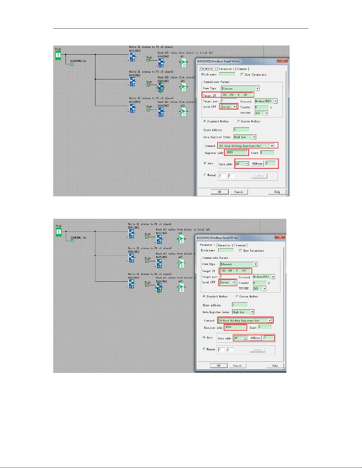
100
If B005 is enabled, the master will read the AI1 value(modbus address 4x 1024) of slave2 and save into local
AF2.
If B006 is enabled, the master will read the AI1 value(modbus address 4x 1024) of slave3 and save into local
AF3.
Slave1--Slave3 Program would be same.
 Loading...