


INSTRUCTION MANUAL EBIKES
RIESE & MÜLLER
AVENUE
CULTURE
DELITE
HOMAGE
KENDU
LOAD
BLUELABEL CHARGER
BLUELABEL CRUISER
BLUELABEL PONY
BLUELABEL SWING
BLUELABEL WAVE
BLUELABEL
TRANSLATION OF THE ORIGINAL GERMAN INSTRUCTION MANUAL

2
Dear customer,
congratulations on your new Riese & Müller E-bike. Thank you for
choosing us for your mobility needs. Riese & Müller builds lightweight
and practical E-bikes that are characterized by exceptional handling
and award winning design. During the design process, we constantly
think about your riding enjoyment and safety. Even though we cannot
anticipate every possible scenario, this manual answers many of the key
questions you may have and gives you many tips on using your bike.
Furthermore, a lot of interesting facts about bicycle technology, main
tenance and upkeep are summarized for you to ensure that you enjoy
your new Riese & Müller E-bike for many years for come. Since our
E-bikes are constantly being updated and improved, we may provide
additional supplementary pages to ensure you have the most up to
date information. Please be mindful that some updated information
may have already been included with your new E-bike.
Your dealer has performed the final assembly of the E-bike and possibly
implemented some requested changes for you. He has performed a
test ride to ensure an enjoyable riding experience from the very start.
If after reading this manual, you still have questions, please feel free to
contact your dealer or us directly.
The Riese & Müller Team

3
CONTENT
General information
Safety
Legal requirements
Intended use
Statutory provisions for fast E-bikes
Before the first ride
Before every ride (quick check)
Quick releases
Adjusting the riding position
Adjusting the rear suspension
Suspension seat post (blueLABEL)
Adjusting the suspension fork
Braking system
Shifting system
Chain
Belt drive
Wheels and tires
Repairing a puncture
Headset
Lighting system
Luggage and children transport
Integrated lock
Kickstand
Pedals
Load – separating the frame
Bosch drive
E-Bikes – range in cold weather
E-Bikes – HS models
Transporting the E-bike
General care / Inspections
Warranty / Guar antee
Weight rating
Recommended torque settings
Service and maintenance plan
Documents
Service record
4
6
8
9
10
12
14
16
18
26
31
32
33
39
44
46
47
51
58
59
60
61
62
62
63
64
66
67
68
70
74
77
78
80
82
83

4
Carrier, S. 60
Seat post, S 18, S. 31
Saddle, S. 20
Shifting
Derailleur, S. 41
Hub gear, S. 42
Wheel attachment, S. 16
Wheels and tires, S. 47
Kickstand, S. 62
Brake lever, S. 25
Shifter, S. 40
Stem, handlebar, S. 21
Headset, S. 58
Lighting, S. 59
Suspension
fork, S. 32
Brakes
Disc brakes,
S. 35
Rim brakes,
S. 36
Bosch drive, S. 64
Chain, S. 44
Belt drive, S. 46
Pedals, S. 62
Suspension, S. 26

5
Torque settings in this manual are
specied in Nm. Do not rely on
your feeling: “tight” is simply not
precise enough. ONLY a torque
wrench can ensure that the bolt
is properly tightened. You must
always use this tool to tighten
the components when a torque
setting is specied. A bolt that is
too tight or too loose can cause
malfunctions which could lead to
an accident with serious injuries
as a result.
DANGER!

6
GENERAL INFORMATION
DANGER!
Do not ride if the test wasn’t
passed with 100 % certainty.
Riese & Müller E-bikes are equipped with exceptionally innovative technology. Even if you are
a seasoned rider that has been riding for many years, we strongly recommend reading and
observing the following instructions.
First we would like to familiarize you with the components of your Riese & Müller E-Bike.
Please flip open the front cover of the manual. Here you will find an example of a
Riese & Müller E-bike upon which all of the mentioned components are identified.
TIP! KEEP THE FRONT COVER OPENED AS THIS MAKES ORIENTATION EASIER!
We have tried to vividly portray all of the relevant information to ensure your satisfaction
with your new Riese & Müller E-bike. Therefore we use the following symbols:
Attention! Here is a hint that will help you quickly become familiar with your bike
and its technology.
Danger! This symbol indicates that life-threatening risks are possible if the
corresponding instructions are not followed. Please read carefully.
Tip! This symbol indicates useful additional information.
This symbol indicates that you must use a torque wrench and comply with
the specified torque.
To ensure you always have a fun and safe ride, you should perform the quick check before
every ride. For instructions on this quick check please visit page 16.

7
This manual covers the installation and maintenance work that may be best
performed by your local dealer (page 80 – 81). Do not perform any task that
you are uncomfortable with. Many of these tasks require special knowledge
and tools and should only be performed by an expert. Never ride your bike
with incomplete or improper maintenance. You could endanger your life or
the lives of others.
DANGER!
In this manual, a number of maintenance and repair tasks are described in detail. If you
engage in this activity you must always consider that the instructions are exclusively for the
designated Riese & Müller E-Bikes and are not transferable to other bikes.
Through a variety of design and model changes it is possible that the included instructions are
not up to date. If necessary, review the separately attached instructions.
Note that the successful execution of the included instructions may require special tools or
technical expertise. If you are uncomfortable performing any of the listed tasks, please seek
the assistance of a professional.
If you reach a certain point where you are not sure how to proceed, please contact your local
dealer or us directly. We are happy to help!
WE HOPE YOU ENJOY YOUR NEW RIESE & MÜLLER EBIKE.

8
SAFETY
The following are a few things that we hold very dear:
• Always take care in trac as not to endanger yourself or others.
• Respect the rules of the road so you don’t draw the ire of other road users.
• If you tour through forests and meadows, please respect nature by cycling
only on marked or paved roadways. Observe the legal requirements for the
o-road use of bicycles. These are available from your local authorities.
• Never ride without a helmet.
• Make sure you always wear appropriate clothing.
• Make sure you always wear shoes with non-slip and rigid sole.
• Do not ride with hands o the handlebar.
• Do not ride with headphones and do not use your phone on the E-bike. do
not drive if you are impaired in your driving ability by medication, alcohol or
other drugs
• Check if the quick releases, thru axles or axle bolts are properly secured. Do
this before every ride and even if you only shortly parked your E-bike.
• Adapt your driving style to the weather conditions. Wet or slippery roads
increase the braking distance.
• Adjust your speed to the terrain and your riding ability.
Note to all parents and guardians
As guardians you are responsible for the technical condition of E-bike and the
safety of your child.
ATTENTION
Minors may only ride E-bikes, when they
have reached the required age and possess
the necessary license respectively.

9
DANGER!
Shut off the E-bike drive and remove the battery before you start to work at
your E-bike. Unintended activation of the E-bike drive can lead to injuries.
Note that the E-bike immediately moves when you put your foot on the pedal
and the E-bike drive is switched on. So rst pull the brake and then get on the
E-bike. Otherwise the unexpected move can lead to accidents and hazards.
DANGER!

10
LEGAL REQUIREMENTS
If you want to participate on public roads
with your E-bike, your E-bike must be
equipped in accordance with local regula
tions. In Germany this is governed by the
Road Trac Licensing Regulations (StVZO)
and the Road Trac Act (StVO).
STVZO
To legally use a bike on a public road in
Germany it must conform to the Road Trac
Regulations (StVZO). The requirements relate
to the brake and lighting system and bell.
Every rider is obliged to maintain his bike
at a roadworthy state. The general trac
rules that apply to automobiles also apply to
bicycles. Please familiarize yourself with the
trac regulations.
THE BRAKING SYSTEM
The braking system of an E-bike must have
at least two independently functioning
brakes (front and rear wheel). The mode of
operation is not strictly regulated.
DIE LICHTANLAGE
All lighting devices on the bike need to dis
play the ocial mark. This mark consists of a
wavy line, the letter “K” and a number. Only
lights (battery powered and dynamo) with
this mark can be used on public roads.
The §67StVZO states that the front and rear
light must be operated by the same fixed
power source (battery or dynamo). Front and
tail light can be switched on and o sepa
rately. The rated power and voltage must be
at least three watts or six volts. The rear light
must be mounted at a height of at least
25 cm above the road surface and the center
of the front light cone must touch the road
surface no further than 10 meters from the
front of the E-bike.
REFLECTORS
In addition to the light sources, each bicycle
must also have the following reflectors:
• as large as possible white reflector in
combination with the headlights.
• in the rear, at least two red reflectors with
a large area with the “Z” mark. The tail light
can be combined with the rear reflectors.
• two lateral yellow reflectors per wheel
must be attached. Alternatively white
reflective rings can be attached to the
spokes around the complete circumference
of the wheel or on the rim edge or on the
sidewalls of the tires.
• two yellow reflectors per pedal
(front and rear).
TIP!
Before using your bicycle in a country
other than Germany you can seek
advice at your local dealer regarding
any legal peculiarities in your country

11
INTENDED USE
Your Riese & Müller E-bike is designed for
use on roads and paved trails only. When
using the E-bike in public trac it must be
equipped conforming national legislation.
Your E-bike is not approved for extreme
loads. Riese & Müller is not liable for dam
ages resulting from improper use, incorrect
assembly, negligence, accidents, racing,
jumping, wheelies or similar activities.
Your E-bike is not approved for use in
competitions.
Terms of use and maintenance described in
this manual are part of the intended use.
The manufacturer or dealer accepts no
liability or warranty if the E-bike is out of
intended use, when safety instructions are
not observed, when overloaded or
improperly deficiencies are eliminated.
The warranty does not cover damage caused
by installation errors, intent, crashes and
poor care or poor maintenance.
DANGER!
Your E-bike is basically intended
for the transportation of a single
person only. One exception is
the transportation of a child in
a child seat or a child trailer.
Please note the terms of your
national legislation.
Pay attention to the use of high
quality child seats and trailers.
Pay attention to the maximum
gross weight (see page 77,
technical data).
TIP!
Gross weight =
Riders weight +
E-bike weight +
luggage weight

12
LEGAL FRAMEWORK
The following paragraph applies to the
Federal Republic of Germany. Please refer
to your local regulations in your country. If
you were born after April 1, 1965, you need a
license (regardless of class) to use a fast
E-bike on public roads. You also need insur
ance and a license plate. These can usually
be obtained at your local insurance oces.
You’ll need to bring the vehicle documents
you received from your dealer. We recom
mend comprehensive vehicle coverage.
Please mount the license plate on the
included holder (see picture).
BICYLE HELMET
A fast E-bike is capable of speeds over
40 km/h, a speed range previously reserved
for scooters and motorcycles. Although
you are not required to wear a motorcycle
helmet, we STRONGLY encourage the use of
a bicycle helmet.
USAGE OF CYCLE PATHS
Please familiarize yourself with the trac
regulations for fast E-bikes in your country.
REFLECTORS AND REARVIEW MIRROR
Please familiarize yourself with the trac
regulations for fast E-bikes in your country.
TRANSPORT OF CHILDREN
Please familiarize yourself with the trac
regulations for fast E-bikes in your country.
MODIFICATIONS AT FAST EBIKES
Your vehicle’s technical capabilities were set
and approved in our factory. Therefore any
adjustment to certain components of your
fast E-bike voids the approval.
STATUTORY PROVISIONS FOR FAST EBIKES

13
The following components may, subject to
certain conditions, be replaced/exchanged:
Tires ECE-R75 approved tires of the same
width and diameter (other tire sizes
possible, see details in the registra
-
tion document).
TIP!
All other components must be replaced
by identical parts or parts with ocial
type approval. Or the parts must be
presented to a technical service like
TÜV or DEKRA and listed in the regis
-
tration paper of the E-bike.
14
BEFORE THE FIRST RIDE
Make sure that your dealer has performed
the final assembly of the E-bike and adjusted
the E-bike to your preferred riding position.
This includes:
• adjustment of the brakes
• adjustment of the brake levers, so you can
reach them every time
• wheel attachment to frame and front fork
• adjustment and attachment of saddle,
handlebar and stem for a secure and
comfortable riding position
CARRIER, CHILD SEATS
Please note that carrier and child seat are
not allowed to be modified. The following
E-bikes can be directly fitted with a child seat
(eg Polisport Bilby): Avenue, Culture, Delite,
Homage, Cruiser, Swing, Wave
TRAILES/TRAILERBIKES
Riese & Müller E-bikes are only approved
for use with two wheeled trailers. The max.
towing capacity (including trailer weight)
is 50 kg. When mounting the trailer at the
carrier, please add the support load to the
carrier load.
Single-track trailers are approved for the use
on blueLABEL E-bikes only. The maximum
trailer load is 20 kg.
DANGER!
If your E-bike is tted with pedals with rubber or plastic cage,
please become familiar with
their grip. Pedals with rubber
or plastic cage may get slippery
when wet!
The authorized dealer must make
the E-bike ready to ride, so that safe
operation is guaranteed. The dealer
must do a nal check and a test ride
with your E-bike. The transfer of the
E-bike must be documented in the
e-Bike passport (see page 87).
Check the tight t of quick releases
and all important bolts and nuts.
Check the tires air pressure. You will
nd the required air pressure at the
sidewall of the tires. Do not exceed
the minimum and maximum air
pressure! Make sure that tires and
rims are free from damages, cracks
and deformations.
Check the tight t of the battery.
Check the battery charge condition.
Become familiar with the functions
of all controls.
ATTENTION!
Child trailers are not allowed
on fast E-bikes.
ATTENTION!

15
BRAKING SYSTEM
Are you familiar with the braking system?
Check to make sure that the front brake lever
is on the side of the handlebar that you are
used to. If it isn’t then you can either train
with the new arrangement or have your
dealer change the arrangement to fit your
needs. More details on brakes can be found
on pages 33.
SHIFTING
Conduct a test ride to familiarize yourself
with the shifting system in a low-trac area.
More details on the shifting on page 39.
SEATING POSITION
Is the saddle and handlebar in the right
position? Your dealer can assist you in
finding the best seating position. More
details on seating position on page 18 – 25.
SUSPENSION
Is the suspension adjusted to suit your
needs? More information regarding
suspension on page 28 –36.
DANGER!
Modern brakes are much more
powerful than simple rim or
drum brakes. Make sure to rst
test the braking power before
heading into trac. Unintended
braking can lead to an accident.
Slowly squeeze the brake to
generate more braking force.
When riding with a full load, the
handling is affected and it takes
longer to stop. Be sure to make
some handling and braking test
prior to heading into trac.
DANGER!
With activated E-bike drive, the
E-bike immediately moves, when
you put a foot on the pedal! So
pull the brakes before getting on
the E-bike. The unaccustomed
move may lead to hazards and
accidents.

16
DANGER!
BEFORE EVERY RIDE QUICK CHECK
Before each ride the following items must
be checked:
QUICK RELEASE/AXLE BOLTS/THRU AXLES
Are the quick releases or bolts of stem, sad
dle, front and rear wheel properly secured?
More details can be found on page 16 – 17.
SUSPENSION
Check to make sure the suspension is
functioning. Press down on the saddle to
check the rear saddle. While holding the
front brake, press down on the handlebars to
check the suspension fork. In both cases the
suspension should move up and down with
uniform resistance and without significant
noise. No components of the bicycle should
scrape or rub together.
TIRES
Sind die Reifen in gutem Zustand? Stimmt
der Are the tires in good condition? Is the air
pressure correct? More information regard
-
ing tires can be found on page 47–50.
LIGHTING
Do the lights stay on when standing still?
More information regarding lighting can be
found on page 59.
BRAKES
Vigorously pull the brake lever. The levers
should stop just before reaching the han
dlebar. The brake pads on rim brakes must
touch the entire rim area while not touching
the tire. More details on the brakes can be
found on page 33 – 38.
Quick releases and ttings that
are not properly closed can
result in severe accidents!
Check the tight t of quick
releases, thru axles and bolts
even if you parked your E-bike
only shortly at an unattended
place. Do not ride your E-bike
with untightened quick releases.

17
LOADING
Check the fixation of basket or child seat. The
luggage must be fixed securely and noth
ing should get caught by the wheels. Please
note that your E-bike may change under
loading.
WEIGHT LIMITS
Check to ensure the gross vehicle weight rat
-
ing is not exceeded. Please see page 77.
UNUSUAL NOISES
Be aware of any unusual noises or changes
to handling characteristics which may
indicate a problem. Check the bearings and
couplings.
DANGER!
Do not ride your E-bike if concerned about any of these points!
If in doubt please consult your
dealer. A faulty E-bike can result
in accidents!
ATTENTION!
After a crash or accident your
dealer must inspect the E-bike for
damages before you use it again.

18
QUICK RELEASES
Even though quick releases are very convenient, many accidents occur because of
their misuse. So please pay attention to this
article
DESIGN OF QUICK RELEASES
The quick release consists of two control
elements:
• A lever A on one side of the hub that pro
-
duces the clamping force.
• A locking nut B which is threaded on the
opposite side that sets the tension
HANDLING OF QUICK RELEASES
• Open the lever A You should now be able to
read the word “Open“.
• To close it, move the lever so that on the
outside it reads ”Close“. At the beginning
of the closing movement, about halfway
through its travel, the lever must be slightly
tight.
• During the second half of the lever’s travel,
the leverage increases significantly. Finally,
the lever is very tight and is dicult to
move. Use the palm of the hand to close
the lever. Once closed the lever must be
parallel to the wheel and not project out
laterally.
B
A
OPEN
CLOSED

19
• Check the fit by attempting to turn the
closed lever. When the lever rotates, it is
not safe to use the bike. You have to open
it again to retighten it. Do this by turning
the locking nut one-half turn (while holding
quick release).
• Repeat the closing process and check the fit
again. When the lever no longer rotates, it
is clamped properly.
• Check the tightness of the wheel: lift the
wheel several inches o of the ground and
give the top of the tire a little whack. A
securely fixed wheel should remain in the
frame.
• Check the tight fit of saddle and handlebar
by trying to twist them.
TIP!
Components secured with a quick
release are at risk of theft.
If possible place an additional
lock on the wheels when you park
the E-bike.
DANGER!
Never ride a bike without rst
checking that the wheels are
securely attached to the frame
with a quick release or bolt.
If not securely attached, the
wheel could fall out during the
ride and lead to a severe injury!
Check the tight t of quick
releases, thru axles and bolts
even if you parked your E-bike
only shortly at an unattended
place. Do not ride your E-bike
with untightened quick releases.

20
ADJUSTING THE RIDING POSITION
RIDING POSITION
The correct riding position is essential for
comfort and power delivery. Your E-bike is
designed so that he various components can
be adjusted to accommodate your body size.
This section describes adjusting the riding
position on your new Riese & Müller E-bike.
CORRECT SEAT HEIGHT ADJUSTMENT
The necessary height is based on body posi
tion while pedaling. While pedaling the balls
of the big toes should be over the pedal axle.
The leg must not be fully extended at the
lowest position of the pedaling circle. If the
seat is too high, it is dicult to pedal through
this low point and the pedaling is not smooth
and circular. If the seat is too low, knee pain
is possible.
Check the seat height using the following
method and be sure to wear shoes with a
flat sole:
• Sit on the saddle and place the heel on the
pedal in the lowest position. In this position
the leg should be fully stretched. Make sure
that your hips remain straight.
DANGER!
The successful execution of the
following operations requires
some experience, proper tools and
expertise. Make sure to conduct a
brief check (page 14) and test ride
in a trac free area. If you have
any doubts about the adjustments,
please discuss them with your
local dealer. This can be combined
with a normal workshop visit (i.e.
initial inspection).
TIP!
With full suspension bikes, the bottom
bracket height is inherently greater.
It may happen that you can only reach
the ground with an outstretched toe.

21
• To adjust the seat height, you must loosen
the clamping screw for the seat post.
• Now you can adjust the seat post height.
Make sure that the seat post is greased.
If the seat post feels tight, clean and re
grease both surfaces. Never force the seat
post and if you have further issues, please
contact your local dealer for further advice.
• Align the saddle in the direction of
travel and tighten the clamping
screw to a torque of 9–12 Nm.
• Check the tightness of the seat post. Try to
twist the saddle. If it doesn’t twist, the seat
post is tight.
• Double check to make sure the leg exten
sion is correct. Verify that you can easily
and safely reach the ground. If this is not
the case, position the saddle lower.
Never ride when the minimum
insertion mark on the seat post
is visible. This indicates that
the seat post is not inserted far
enough into the frame. It could
break or damage the frame. If
the seat post is ever shortened, a
minimum of 80 mm must remain
in the seat tube!
DANGER!

22
ADJUSTING THE RIDING POSITION
SADDLE ORIENTATION AND ANGLE
The distance between the handlebars and
saddle and the angle of the saddle have an
eect on riding comfort and riding dynam
ics. By moving the saddle horizontally, this
distance can be altered which has a pro
found eect on pedaling. Furthermore, the
seat should usually be oriented parallel to
the ground.
• Loosen the bolt A three to four turns only,
otherwise the entire mechanism may fall
apart.
• Move the seat forward or backward as
desired. Often this only requires a little
bump to the saddle.
• Adjust the angle.
• Tighten the bolt A
to 12–15 Nm.
• Check to see if the tightened saddle moves
by alternately loading the front and back of
the saddle.
DANGER!
When replacing the saddle, be
aware that only saddles with a
frame diameter of 7 – 8 mm can
be used. Using saddles with other
frame diameters can lead to failure and cause the rider to fall.
A
A
TIP!
The Riese & Müller ip op seat post
can be rotated with its head facing
forward to get a smaller distance to
the handlebar.

23
HANDLEBAR HEIGHT ADJUSTMENT
The stems at Riese & Müller E-bikes are
height and partially angle adjustable. This
allows for the adjustment of the seating
position.
Upright seating position
Advantages: less strain on the wrist, arms
and neck.
Disadvantages: higher load on the saddle.
Outstretched seating position
Advantages: less load in the saddle, more
ecient power transfer, more streamlined,
more weight on the front wheel.
Disadvantages: higher load on wrists, arms
and neck.
HANDLEBAR HEIGHT AT ERGOTECSTEMS
The height can be reduced by leaving o
spacers. But the steerer tube has to be
cutted in the same way.
ATTENTION!
Let your dealer change the handlebar height.

24
ADJUSTING THE RIDING POSITION
Height Adjustment:
• Open the quick release lever C.
• Press the pin D and adjust the stem to
one of five height positions until the pin D
engages.
• Attention: the stem should not be extend
ed beyond the “MIN. INSERTION“ mark!
Use the stem only in the five positions in
which the pin engages.
• Align the handlebar in the direction of
travel and close the quick release lever C.
C
D
ADJUSTABLE STEM AT KENDU/ LOAD/PONY
The stem of the Kendu, Load and Pony is
adjustable in both height and angle. Both
adjustments can be made without tools by
means of a locking pin and quick releases.
Angle adjustment:
• Open both quick release levers A on the
front hinge.
• Press the side button B and adjust the stem
in one of the three angle positions. Release
the button again moving the stem until it
clicks into place (possibly move the stem a
little back and forth).
• Attention: Only use the stem in the three
positions in which the pin engages!
• Close both quick release levers A.
• In engaged state both red marks are in one
line.
A
B
ATTENTION!
Before each ride, ensure that the pin
is rmly in place and quick-release
levers are completely closed. If the
bars or stem move while driving by
yourself, have your dealer inspect
it immediately as this could be very
dangerous.

25
DANGER!
The height adjustment of
A-Headset stems requires properly setting the steering bearings
and improper installation can
result in accidents. Therefore it
is recommended that this is only
performed by or at least checked
by your local dealer.
HANDLEBAR HEIGHT FOR AHEADSET STEMS
The height is adjusted by using spacer rings.
26
ADJUSTING THE RIDING POSITION
F
H H
H
H
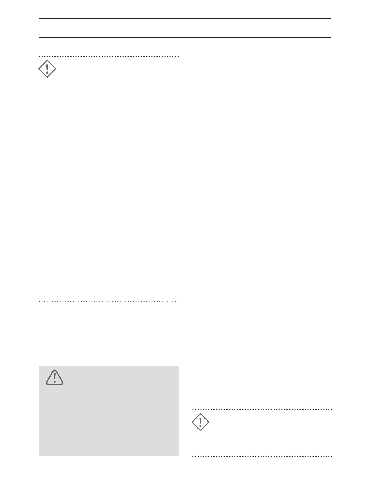
ADJUSTING THE ANGLE OF THE HANDLEBARS
Adjust the handlebars so that the wrists
are relaxed and not too strongly twisted.
Adjust the handlebar position by rotating the
handlebar.
• The Bosch display may cover the bolts of
the handlebar clamp. In this case you must
loosen the four display bracket bolts and
twist the display.
• Loosen the two bolts F or the four bolts H
on the handlebar clamp.
• Rotate the handlebar to the desired posi
-
tion.
• Make sure that the handlebar is clamped
exactly in the middle of the stem.
• Tighten the two bolts F to a torque setting
of 10 Nm or the bolts H to a setting of
5.5 Nm using an “X” pattern.
• Re-tighten the Bosch display bolts again.
The handlebar clamp at the stem of Load/
Kendu/Pony must be tightened first and
gapless at the inscripted side (see arrow A).
Observe the tightening torque (6–8 Nm).
Fix the handlebar by tightening the opposite
bolts.
After modications of stem and
handlebar position you must
check if all cables are still long
enough. It is necessary to have
the full steering range without
any limitations by the cables.
DANGER!
HANDLEBAR ADJUSTMENT
When adjusting grip position, adding bar
ends or changing handlebars, it may be
necessary to replace shifting and brake
cables with longer ones.
A B

27
ADJUSTMENT OF VBRAKE LEVER REACH
Riders with small hands can adjust the brake
lever closer to the handlebar:
• Where the brake cable enters the brake
lever there is a small screw. Tighten the
screw until the desired reach is achieved.
• Now check whether there is enough
free travel of the lever before the brake
engages. If this is not the case, the brake
cable can be adjusted (see page 20).
BRAKE LEVER ROTATION
Loosen the Allen bolts on the brake lever
handlebar clamp.
• Sit on the saddle and put your fingers on
the brake lever. Then twist the brake levers
until your hand and forearm form a
straight line.
• Tighten the bolts on the brake lever
handlebar clamp to a torque setting of
5 – 6 Nm.
BAR ENDS
These provide an additional grip position.
They are usually set so that the hands fit
comfortably on it when the rider is leaning
slightly forward. The bar ends are typically
set at approximately 25 degrees
to horizontal direction.
DANGER!
The brake lever should not touch
the handlebar before full braking
is achieved!
DANGER!
The bolts on the stem, handlebar, grips and bar ends must be
tightened to the specied torque
settings. The corresponding
values can be found on page 78.
If bolts are not tightened to the
correct specication it may
cause the parts to loosen or
break which may lead to serious
accidents.

28
DANGER!
ADJUSTING THE REAR SUSPENSION
Your Riese & Müller E-bike is equipped with
a low maintenance rear suspension system
(excluding blueLABEL). The shock contains
either an air chamber or a combination
of steel spring and oil hydraulic damping.
To tune the air suspension, please refer to
the separately included manual from the
suspension manufacturer.
REAR SUSPENSION ADJUSTMENT
With steel spring shocks, the correct spring
must be chosen for the desired ride char
acteristics. Furthermore you can adjust the
spring preload and damping.
The standard spring is designed for 90 % of
all applications. If the bike sinks dramatically
when you mount it or bounces when hitting
small bumps, you need a stier spring. If the
bike sinks only a little when you mount it
and hardly reacts to bumps, then you need
a softer spring. Riese & Müller oers softer
and stier springs in order to meet specific
customer requirements.
The adjustment ring of some E-bike models
is fitted with holes and can easily be ad
-
justed by a 3 mm Allen key.
If you do not have the special
knowledge or the special tools
for this work, you must contact
your dealer.
29
DANGER!
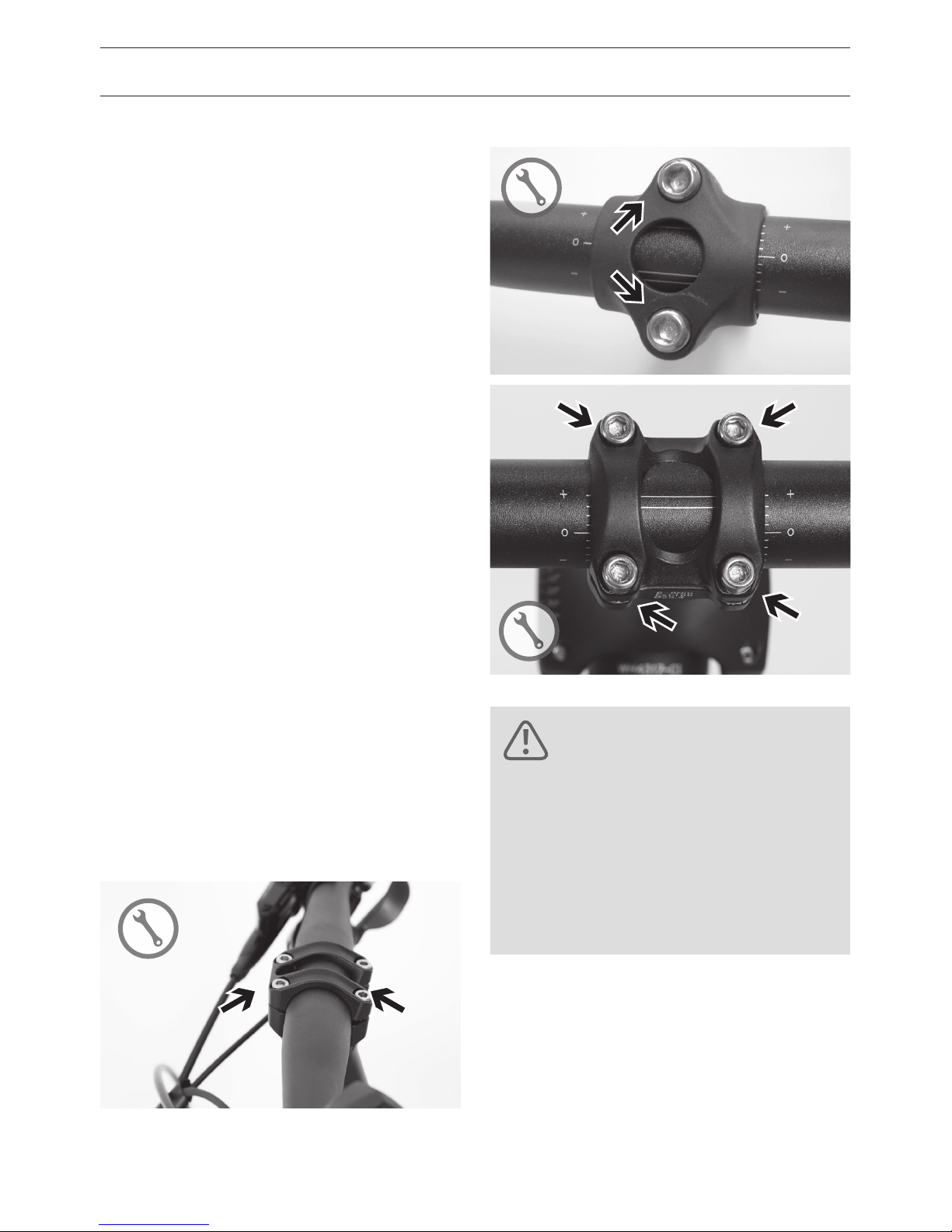
REPLACING THE SPRING
• Hang the bike in an assembly stand.
• Relax the shock fully. Rotate the adjust
-
ment ring counterclockwise.
• Prevent the swingarm from accidentally
folding down with the help of a stable
cord or cable ties between the frame and
swingarm.
• Loosen the bolts at both ends of the shock
with a 5 mm Allen wrench and a 10 mm
wrench. Carefully remove both bolts. Look
for the washers and remember their orien
-
tation for later reassembly.
• Remove the bushings B from the side of
the shock with the adjustment ring.
• Turn the adjustment ring A until it is
removed completely from the shock.
If the swingarm is not secured,
it could fall down injuring you
or damaging the bike.
If the bike is placed on the
ground while disassembling the
shock, the rear swingarm can
fold under suddenly. There is
a risk of pinching your hands
between the bike frame and
swingarm or damaging the bike
itself!

30
ADJUSTING THE REAR SUSPENSION
• Pull the spring plate D and remove the
spring.
• Clean the threads and apply some grease.
• To reinstall the shock, repeat the process in
reverse order.
• Put the shock back in the frame and tighten
the screw connections (torque 7 – 9 Nm).
ADJUSTING SPRING PRELOAD
With spring preload, you set how far the
suspension sags when you sit on the bike.
Ideally it should be between 20 and 25 % of
the total travel.
Sag to great
The shock requires more preload. Turn the
adjustment ring A (see fig. at 27) page-
clockwise.
Sag to little
The spring needs less preload. Turn the
adjustment ring A counterclockwise or use a
softer spring.
The adjustment ring should not be
tightened more than three rotations.
If after three rotations, the preload is
still not enough, you require a stiffer
spring. For optimal suspension
convenience, the spring should
require as little preload as possible.
ATTENTION!
Ensure the adjustment ring is not too
loose. The spring on the unloaded
E-bike should not t loosely.
ATTENTION!

31
DANGER!
ADJUSTING DAMPING
Rebound damping of the shock determines
how the rear swingarm returns to its original
position after being loaded. To test, ride o
of a curb. The suspension should bounce
back at once. If the suspension oscillates in
stead of coming directly back to the original
position, turn the knob clockwise to increase
damping. If the suspension rebounds too
slowly and over several closely spaced
bumps sinks continually lower, the damping
can be reduced by turning the knob counter
-
clockwise.
When working on a shock, never
load the shock by leaning on the
E-bike’s saddle, handlebars or
racks. One can simply pinch his/
her hands compressing the rear
suspension.
While riding under heavy compression, the fender struts come very
close to the frame or rack. From
time to time, check the adjustment
of the rear fender. The front struts of
the rear mudguard (Avenue, Culture
and Homage) contain a bend that
prevents the struts from grinding on
the frame or luggage rack. Grinding
struts can permanently damage the
frame!
ATTENTION!

32
MAINTENANCE OF THE SHOCK
The steel spring shocks used by
Riese & Müller oer very good suspension
characteristics and user-friendly service
intervals. Shocks used under normal
conditions only need to be serviced every
5000 km. When riding on rough roads /trails
or harsh snow conditions, it is advisable
to perform maintenance more frequently to
prevent premature damage.
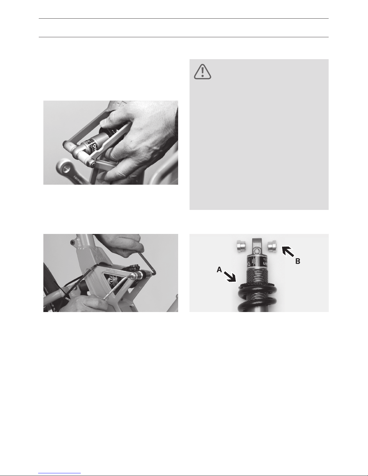
During servicing, the shock should be re
-
moved and the following parts cleaned:
• Mounting bolts
• Bushings A
• Threads B
• Piston rod C
The following parts should be greased:
• Bushings A only for X-Fusion Shocks
• Threads B
For information regarding the maintenance
of air suspension shocks please see the
separately enclosed manufacturer’s instruc
-
tions.
ADJUSTING THE REAR SUSPENSION
A
A
A
A
B
C
ATTENTION
Let your dealer do the maintenance work at the suspension.

33
The stiness of the seat post can be adjusted (within certain limits) to the weight of
the rider.
• Open the seat post clamp on the frame and
remove the seat post from the frame.
• Adjust the spring preload with a 6 mm Allen
key. Turn clockwise to increase the tension.
Rotate counter-clockwise to decrease the
preload. The preload can only be reduced to
the extent that the adjustment screw
D doesn’t project out of the seat post.
• Install the seat post in the frame
(see page 21 ).
If the lateral play between shaft and outer
tube is too great you can rotate the nut E by
hand to make it a bit harder. Make sure that
the boot does not slip o of the nut. Do a
regular check if the nut E has a tight fit
SUSPENSION SEAT POST (ONLY FOR blueLABEL)
D
E

34
ADJUSTING THE SUSPENSION FORK
AIR SUSPENSION FORKS
With air suspension forks, the preload is set
using the standard (supplied) air pump.
For details regarding the adjustment of
these forks, please see the separately en
closed instructions from the shock manufacturer. Please also visit the manufacturers
homepages at the Internet:
• www.ridefox.com
• www.xfusionshox.com
• www.srsuntour-cycling.com
Maintenance of suspension forks
Please refer to the notes in the separately
enclosed instructions from the various
suspension fork manufacturers.
DANGER!
When rotating in the “-” direction and you receive some
resistance, you should not
continue turning to prevent over
loosening the tting. This could
cause an accident!
DANGER!
The suspension components at
your E-bike are safety-relevant.
Check and maintain the suspension components of your E-bike
on a regular base or let this be
done by your local dealer.
Suspension fork adjustment
The sag for the suspension fork should also
be approximately 20 %.
With RST and Suntour suspension forks, you
adjust the preload with one or two knobs
on the fork crown. Turning the knob towards
the “+” will increase the preload, turning it
towards the “-” reduces preload.
Should the amount of adjustment prove
insucient, please contact your dealer.
He can check if your front fork can be tuned
harder or softer.

35
DANGER!
DANGER!
BRAKING SYSTEM
USE BRAKES PROPERLY
The brakes on Riese & Müller E-bikes allow
you to achieve powerful braking with little
hand force. The stopping distance however
depends also on the rider’s skill. No worries
as this can be trained. When you brake, your
weight is shifted to the front wheel from the
rear wheel. The strength of the deceleration
is the primary factor in bicycle rollover with
the secondary factor being the traction of
the tires. This can be particularly problematic
when riding downhill. During an emergency
stop try to shift your weight as far back as
possible.
Press both brake levers at the same time
and note that the front brake transmits
much more braking force due to the shifting
weight. Avoid, however, locking the front
wheel as this can cause slipping or even a
rollover.
On slippery ground you must use the front
brake carfully to prevent an uncontrolled
slide away of the front wheel.
ORIENTATION OF THE BRAKE LEVERS
If your E-bike is equipped with a coaster
brake and only one hand brake, the brake
lever will be located on the right side and
will operate the front brake. If your bike is
equipped with two brake levers, the one on
the right operates the rear brake and the
one on the left operates the front brake.
Familiarize yourself with the orientation
or ask your dealer to change them to your
liking.
Make sure to familiarize yourself
with the brakes gradually.
Practice emergency braking in
a trac-free area until you are
able to safely control the E-bike.
This can prevent accidents while
on the road.
Some dealers change the orientation of the brake levers because
there are different opinions as
to which orientation is correct.
Therefore please check before
your rst ride, whether the
above orientation matches your
E-bike and your preferences.

36
OPERATION
By using a brake lever or reverse pedaling a
fixed pad is pressed onto a rotating brak
ing surface and causes friction. This friction
causes the rotating wheel to slow. In addi
tion to the force with which the pad presses
against the surface, the so called friction
coecient between the fixed pad and the
braking surface is crucial. If water, dirt or oil
gets onto the braking surface, the friction
coecient is worsened. This is the reason
why a rim or disc brake does not respond as
well in the rain.
WEAR AND TEAR AT VBRAKES
The friction between the brake pads and the
rim leads to the wearing of both the pad and
the rim! Riding often in the rain increases the
wear. If the rim sidewall is abraded to a criti
cal level, the tire pressure will cause the rim
to burst. The wheel can jam or the tube may
burst, both of which can lead to an accident.
By the time you have worn through your
second set of brake pads, it is time to have
your dealer check the thickness of your rims’
sidewalls. For rims with a wear indicator A,
the rim must be replaced when the indicator
is no longer visible.
Moisture decreases the braking
effectiveness. When riding in rainy
conditions expect longer braking
distances! When replacing brake
pads, you should only use pads that
have been specied for your system.
Your dealer can advise you in the
matter. The braking surface of rims
should be absolutely wax, grease
and oil free.
ATTENTION!
ATTENTION!
Have the rims checked at the latest
after the second set of brake pads.
Worn wheels can lead to material
failures and accidents.
DANGER!
Damaged brake cables in which
individual wires protrude must
be replaced immediately. Brake
failure and an accident can result. Ask your dealer for advice.
A
BRAKING SYSTEM

37
BRAKING SYSTEM
TIP!
New brake pads only reach their
optimum braking performance after
30 to 40 strong braking attempts.
• The braking effect of disc brakes can be greatly reduced when contaminated with
oil, maintenance, or cleaning uids! When cleaning your E-bike or lubricating
the chain make sure you don’t contaminate the rotors. Oily brake pads must be
replaced and brake discs must be cleaned with a brake cleaner.
• After the wheel is removed you should no longer operate the brake lever. The brake
pads will press together making it dicult to mount the wheel. After removing the
wheel, insert the transportation safety shims to ensure a sucient distance between
the brake pads.
• Before every ride, check the brake system for leaks or kinks in the lines. The loss of
brake uid can lead to the reduction and even failure of the brakes! Go immediately
to a dealer to have the leak corrected.
• Do not transport your E-bike with the wheels up as this can render the brakes
ineffective.
ATTENTION!
DISC BRAKES
Maintenance of Disc Brakes
Check the function of the brakes on a regular
base (braking performance, brake pad wear,
leakage). Brake pads must be replaced when
they are contaminated or thinner than one
millimeter. In no condition the brake pad
carrier plate must touch the brake disc.
For information regarding hydraulic disc
brakes please refer to the separate enclosed
instructions from the disc brake manufacturer.
DANGER!
Brake disc and calipers can
heat up during heavy braking.
This is especially true during
long descents. To avoid potential burns do not handle the
brakes right after heavy use.
ATTENTION!
Let the dealer replace worn out
brake pads.

38
BRAKING SYSTEM
VBRAKES
V-brakes consist of separately mounted
brake arms on the left and right side of the
wheel. When the brake arms are pulled to
gether with a cable the pads rub on the rim
generating friction.
Function check
• Check that the brake pads are properly
aligned with the rim and that they have
sucient thickness. This can be seen by
checking the transverse grooves in the
brake pad. When these grooves are worn
down, it’s time to change them.
• Additionally the front portion of the brake
pads should be the first to touch the rim.
Once touching the rear portion of the pad
should be one millimeter away from the
rim. This v-shaped orientation helps pre
-
vent the squealing of the brake pads.
• Both pads must simultaneously hit the rim
when the lever is pulled.
• The brake lever must exhibit a reserve in its
travel. It should not pull up to the handle
-
bars even during emergency braking.
DANGER!
Make sure that the pads touch
the sidewall with their entire
surface. Otherwise brake failure
or wheel lock could lead to an
accident. Make sure that the surfaces of the brake do not touch
the tires. Incorrectly set brake
pads can cause tire rub-through
leading to a tire failure.
Driving direction

39
V-brakes synchronization
The V-brakes have to be synchronized by ad
-
justing the spring preload using the respective adjustment screws A.
• Turn these screws until the pads are the
same distance from the rim.
Adjusting the brake cable
When the brake lever pulls all the way to
the handlebar, the brake cable must be
readjusted.
• Loosen the knurled lock ring B where the
brake cable enters the brake lever.
• Turn slotted barrel adjuster C a few turns.
The free travel of the brake lever is re
-
duced.
• Hold the barrel adjuster C while tightening
the lock ring B firmly against it so that the
barrel adjuster is locked in place.
• Take care that the slot of the adjustment
screw is not orientated to top or front. Oth
-
erwise water and dust could enter.
C
B
A A
TIP!
Be sure to try the brakes in a
trac free area to get a feel for
the newly adjusted brakes.

40
DANGER!
BRAKING SYSTEM
HYDRAULIC RIM BRAKES
For information regarding hydraulic rim
brakes please refer to the separate enclosed
instructions from Magura.
COASTER BRAKES
Some Riese & Müller and blueLABEL models
oer a coaster brake option. Coaster brakes
allow you to apply the brake to the rear
wheel at any time by pedaling backwards.
Riese & Müller only use coaster brakes
whose braking performance is not influ
-
enced by the current gear that one is using.
If your E-bike is equipped with a coaster
brake, you brake by pedaling backwards.
Then you have no freewheel and you can
not move the pedals backwards. The best
way to use a coaster brake is with a horizon
tal position of the pedals. With one pedal on
top you will have bad brake performance
due a a poor force application. On long
downhill passages the brake performance
can decrease due to heating up. So also use
the front brake on long downhill passages
and let the coaster brake cool down.
Before each trip and after any
maintenance work, ensure that
the coaster brake arm is securely
attached to the bracket on the
frame. This connection requires
a torque of 4 – 6 Nm.

41
SHIFTING SYSTEM
THEORETICAL FOUNDATIONS
The shifting system on the E-bike is used to
adapt one’s own performance to the terrain
and the desired speed. The physical work is
not reduced by the shifting system rather
the force required per crank revolution is
changed.
PROPER SHIFTING
Gradients can be powered up using low
gears and moderate force but you’ll have
to pedal faster. Downhill you can travel a
greater distance per turn of the crank. The
speed will be correspondingly high. Like
a car you must maintain your optimum
“engine” speed to perform well. What’s key
to your performance is keeping the number
of crank revolutions per minute (cadence)
above 60. Racing cyclists typically ride with a
cadence of 90 – 110. This rate naturally falls
o a bit during hill climbs but you should still
maintain smooth pedaling. The incremental
shifting steps and ease of use of modern
shifting systems oer the best conditions for
an ecient ride that is easy on your knees.
DERAILLEUR SYSTEM
The derailleur on the E-bike is currently the
most eective systems in terms of power
transfer. In a clean and well-oiled system
about 97 – 98 percent of the energy placed
in the pedals is transferred to the rear wheel.
Despite this near optimal performance, many
cyclists fear a bike without a coaster brake.
This fear is unfounded. The operation of the
derailleur system leaves nothing to be de
sired. With specially designed sprocket teeth,
flexible chains and precisely spaced shifting
steps, the system shifts very easily. Re
member to engage the shifter smoothly and
momentarily stop applying pressure to the
pedals until the chain is on the next sprocket.
Even though the special tooth forms of
today’s sprockets allows shifting under load,
it shortens the life of the chain and therefore
should be avoided.
ATTENTION!
Never pedal backwards while
changing the gears. The shifting
system could be damaged.

42
SHIFTERS
Riese & Müller models with derailleur system
use two dierent types of shifters:
Twist grip
Rotating the right grip towards the driver
leads to an easier gear and rotating the
left grip away from the driver leads to an
easier gear. The grip indicates which gear
you are currently using. The shifter transmits
the commands to the transmission via the
Bowden cable.
Rapid Fire shifter
The thumb on the right side shifts to easier
gears and the index finger on the right side
shifts to harder gears.
Practice shifting in a trac-free
area so that you can become
familiar with the rotation of the
shifters and pressing the levers.
The practice area should be free
of potential hazards. Practicing
in daily trac could affect your
attention to potential hazards.
DANGER!
SHIFTING SYSTEM

43
CHECKING AND ADJUSTING SHIFTING SYSTEM
Your derailleur system was carefully set by
your dealer before handing it over to you.
During the first few kilometers the shift
ing cables may lengthen thereby leading
to imprecise shifting. The chain then only
reluctantly moves to the next sprocket or
chainring.
Tensioning the rear derailleur
• Tension the cable using one of the screws
through which the cable passes (barrel
adjuster).
• After each tensioning check to see whether
the chain moves easily to the next larger
sprocket. To check this you must turn the
cranks by hand or ride the bike.
• If the chain moves easily to the next larger
sprocket, then you must also make sure
that it also changes easily to the next
smaller sprocket. For precise setting,
several attempts may be necessary.
TIP!
If you cannot properly adjust your
shifting system, it could be due to
worn or kinked shifting cables.
Visit your dealer for replacements.
DANGER!
The adjustment of the rear
derailleur is dicult and should
be left to an experienced mechanic. Incorrect settings can cause
serious mechanical damage.
If you have problems with the
system or after a crash or transport damage, please contact
your dealer.
TIP!
In case of derailleur replacement
take care of same cage length as
the original part. Otherwise a
different cage length could lead
to shifting problems because the
chain tension is to low.
44
SHIFTING SYSTEM
Function and operation
It uses a twist grip shifter to select the
desired gears. The chosen gear is indicated.
The IGH requires a momentary pause in the
application of pedal power.
Adjusting gears for internally geared hub
There are several methods used to adjust
gears for IGH and each hub is dierent. For
questions, see your dealer.
SHIMANO 8SPEED IGH
• Shift to the fourth gear.
• Now the two marks on the hub can be
brought into alignment. This is done by an
adjusting screw that the shifter cable runs
through. By turning the screw to the right
the markings move towards the front of
the bike while turning left moves the
markings towards the rear.
INTERNALLY GEARED HUB
One advantage of an internally geared hub
(IGH) is the encapsulated construction. The
technical mechanisms are almost completely
enclosed inside the hub. This prevents con
tamination from dirt and grime. The chain
on an IGH system lasts longer than on an
equivalent derailleur system. A disadvantage
is the slightly higher power losses within the
hub. IGH are sometimes used in combination
with a derailleur, freewheel and rim, roller or
integrated coaster brake.
Practice shifting in a trac free
area. Practice also using the
brakes. In road trac you may
be distracted from shifting and
braking by potential hazards.
DANGER!

45
DUALDRIVE IGH
• Shift the IGH to the middle gear.
• Now the yellow mark inside the clickbox
can be brought into alignment. This is done
by the adjusting screw where the shifter
cable goes into the clickbox.
ROHLOFF IGH
Please follow the instructions in the sepa
-
rately included Rohlo manual.
NUVINCI IGH
Please follow the instructions in the
separately included NuVinci manual.

46
CHAIN
CHAIN CARE
The old saying is still true: “Whoever oils well,
rides well”. The amount of lubrication is not
as important as the distribution and regular
-
ity of application.
• Clean your chain from time to time with a
dry cloth the removed built up dirt and oil.
• Lubricate the most clean chain possible
using chain oil, grease or wax. Wax is a very
clean lubricant which is recommended for
Riese & Müller E-bikes.
• Turning the crank and drizzle or spray
the rollers of the chain. Rotate the chain
several times. Let the bike stand for several
minutes to allow the lubricant to penetrate
the chain links.
• Finish up by wiping excess lubricant o
with a cloth to prevent it from slinging o
while riding.
CHAIN WEAR
Chains are one of the consumable parts on
a bicycle but the lifespan of the chain is
determined by how the rider maintains it.
Be sure the chain is lubricated regularly,
especially after riding in the rain. Chains of
derailleurs often last from 1,500 – 3,000 km
before needing replacement. Greatly elon
gated chains impair shifting and wear down
sprockets and chainrings more quickly.
Replacing these items cost much more than
a chain so we recommend changing the
chain regularly.
CHECKING THE CHAIN TENSION
On bikes with internally geared hubs and
without a chain tensioner sometimes the
chain is insuciently tensioned. It is very
important to maintain the correct chain ten
sion otherwise the chain will hit the inside of
the enclosure and cause noise or a too high
tension increases wear.
How to check the chain tension:
• When grabbed in the rear lower section
and pulled up, the chain should move a few
millimeters only.
TIP!
For the protection of the environment use only biodegradable
lubricants because a small amount
of lubricant always ends up on the
ground, especially during rain.

47
• Check the chain tension at dierent crank
positions.
• Check that the rear wheel is aligned cor
-
rectly in the direction of travel.
• Tighten the bolts A and possibly the brake
anchor with the correct tightening torque.
Checking rear brake and shifting system
The adjustment of the chain tension changes
the rear wheel position. Make sure the rear
brake pads are correctly oriented to the rim
(see page 40).
• If the chain moves more than a few millim
eters down, then it could slap the swingarm
and should be tensioned.
• Shut o the E-bike drive, lift the rear wheel
o the ground and turn the crank. When
the crank is sti and provides uneven
resistance when turning, the chain is too
tight.
ADJUSTING THE CHAIN TENSION
• At models with coaster brake loosen the
brake anchor attachment of the coaster
brake.
• At models without slider dropouts loosen
the axle nuts a few turns. At models with
slider dropouts loosen the four bolts A a
few turns.
• At models without slider dropouts pull the
rear wheel back and tighten the axle nuts
slightly. At models with slider dropouts
tighten the two adjustment bolts B on both
sides with the same number of revolutions.
Turning clockwise tightens the chain and
counterclockwise relaxes the chain.
A
B
The chain tension at the models
Avenue, Culture and Kendu
increases a little bit when the
suspension starts to work.
This is another reason to adjust
the chain tension not to tight.
ATTENTION!
Wrong assembly can cause
malfunction or failure at shifting
and braking system. Absolutely
check the function of shifting
and braking system after chain
tension adjustment.
DANGER!

48
A poorly riveted chain can break
and lead to a fall. It’s best to let
your dealer replace the chain.
DANGER!
REPLACING THE CHAIN
The replacement of a chain is best left to
your dealer who has special tools to accu
rately measure your chain and to cut your
chain to the appropriate length. Many mod
ern chains have no chain lock and a special
tool is required to link up the two halves of
the chain. Your dealer has all of the tools that
match your chain.
REPLACING THE SPROCKET
BELT DRIVE
If your E-Bike is fitted with a belt drive please
follow the instructions in the separately
included Gates manual.
ATTENTION!
At the models Avenue, Culture and
Kendu the front sprocket must
always be replaced by parts with the
same number of teeth. Using other
sprocket sizes affects the chain tension and the chain may snatch
or fall down!
BELT DRIVE

49
WHEELS AND TIRES
The wheels on the bike keep you in contact
with the road. They experience heavy loads
during riding over irregular surfaces and
when carrying cargo. Although the wheels
are carefully manufactured and trued, they
settle in after the first few kilometers. After
a short break-in period from 200 to 400
kilometers, your dealer should true the
wheels again. Regularly check the wheels
but additional tensioning is rarely necessary.
CONSTRUCTION OF A WHEEL
The wheel consists of a hub, rim and spokes.
The tire is mounted to the rim in which the
tube is inserted. Rim tape is applied to
protect the sensitive tube from the often
sharp-edged rim.
TIRES AND AIR PRESSURE
The tire provides grip and traction on the
road which is required during braking,
accelerating, and cornering. Furthermore, it
ensures smooth running. Tires can only work
well if it filled to the correct air pressure.
The correct inflation pressure also prevents
failures such as the crushing of the tube
especially when traveling over an edge, the
so called “snake bite”. Snake bites are caused
when going over an edge such as a curb
with a tire pressure that is too low. The man
ufacturer’s suggested pressure is indicated
on the sidewall of the tire in bar and PSI.
TUBE AND VALVE
The tire and rim alone are not airtight.
To maintain the pressure on the interior,
TIP!
Always ride with the prescribed air
pressure and check it regularly. Because Riese & Müller E-bikes are full
suspension (excluding blueLABEL)
you can always inate the tires to the
maximum recommended pressure.
This provides you the best and safest
riding position and low rolling resistance which saves energy. Comfort is
maintained because of the full suspension system.
TIP!
For the model blueLABEL Charger GT
we recommend an air pressure range
from 1.5 up to 2.5 bar.
Never pump the tires below the
minimum or over the maximum
recommended pressure rating!
The tire can spring from the rim
or burst leading to an accident!
DANGER!

50
WHEELS AND TIRES
the tube is inserted into the tire. It is filled
through a valve. Riese & Müller E-bikes use
presta valves exclusively. Before inflation,
the small knurled nut is unscrewed and
then pressed back down into the valve. It is
normal for a little air to escape during this
process.
If the presta valve is not suciently tight
ened, this leads to the gradual loss of air.
Check the tightness of the of the valve body
in the elongated shaft. Make sure the valve
diameter matches the hole in the rim and
that the valve stands up straight.
CHECKING THE TIRES
Regularly check the tires.
DANGER!
If the tread is worn or the edges
are brittle, you should replace
them. The inside of the tire may
be damaged if is contaminated
by moisture or dirt. Defective rim
tape must be replaced immediately. Damage to the tires can lead
to their sudden bursting which
could be dangerous.

51
RIM RUNOUT AND SPOKE TENSION
The spokes connect the rim with the hub in
the center of the wheel. The uniform spoke
tension is responsible for maintaining the
concentricity of the wheel. When a spoke
breaks when running over a severe bump,
the tension of the spokes is no longer in
equilibrium. Even before the rider notices the
malfunction it is aecting your bike. The side
walls of the rims no longer run parallel to
the braking surface so braking eectiveness
cannot be ensured.
Be sure to check the concentricity (runout)
from time to time. Lift the wheel from the
ground and spin it with your hand. Watch the
gap between the rim and brake pad. If this
gap changes by more than one millimeter it
needs to be trued by a professional.
TIP!
The truing of wheels is dicult
work and is best left to your dealer!
TIP!
Please read more on rim wear
indicators at page 34.
Do not ride with wheels that are
out of true. If the rim is severely
out of true then the brake pad
can miss the rim sidewall and
actually strike the spokes leading
to an accident.
DANGER!
Check the rims for wear and
defects on a regular base. Worn
out rims are more delicate for
defects. V-brakes cause more
wear. A deformed or broken rim
may lead to heavy accidents.
DANGER!

52
B
A
WHEEL ATTACHMENT
The wheels are attached to the frame via ei
ther an axle with a hex nut or a quick release
clamped in the dropouts. More information
on quick releases on page 18 –19.
AXLE NUTS
Note the respective torque settings of the
axle nuts.
THROUGH AXLES
Some Riese & Müller models use a front fork
with through axle. Please follow the instruc
tions in the separately included front fork
manual.
QUICK RELEASES
The quick release consists of two control
elements:
• A lever A on one side of the hub that pro
-
duces the clamping force.
• A locking nut B which is threaded on the
opposite side that sets the tension.
DANGER!
Never ride a bike without rst
checking that the wheels are
securely attached to the frame
with a quick release or bolt. If
not securely attached, the wheel
could fall out during the ride and
lead to a severe injury!
DANGER!
Check the tight t of quick releases, thru axles and bolts even
if you parked your E-bike only
shortly at an unattended place.
Do not ride your E-bike with
untightened quick releases.
WHEELS AND TIRES

53
REPAIRING A PUNCTURE
PREPARING TO REMOVE THE WHEEL
Each model has certain things that must be
done before the wheel can be removed.
These are described below.
Unhook V-brakes
With V-brakes the brake cable must first be
unhooked. Grasp it with one hand, moving
the cable hanger A and the guide tube B
with the other hand. If the brake cable is set
to tight, you can reduce the tension by turn
-
ing the barrel adjuster on the brake lever.
DISC BRAKES
Please note the tips regarding disassembly
of wheels on page 35.
TIP!
Depending on the E-bike model,
the removal and replacement
of the rear wheel may be more
dicult than you are used to.
Carefully read the notes on the
following pages. Should you
encounter any problems your
dealer or Riese & Müller are at
your disposal.
B
A

54
REPAIRING A PUNCTURE
MAGURA RIM BRAKES
Please note the tips in the separately in
-
cluded instruction manual from Magura.
ROHLOFF SYSTEM
Please observe the instructions of the sepa
-
rately included Rohlo manual.
DERAILLEUR GEAR
Before removing the rear wheel of derail
leur systems, be sure to shift to the smallest
sprocket. Thus the derailleur is all the way to
the outside and does not hinder the removal.
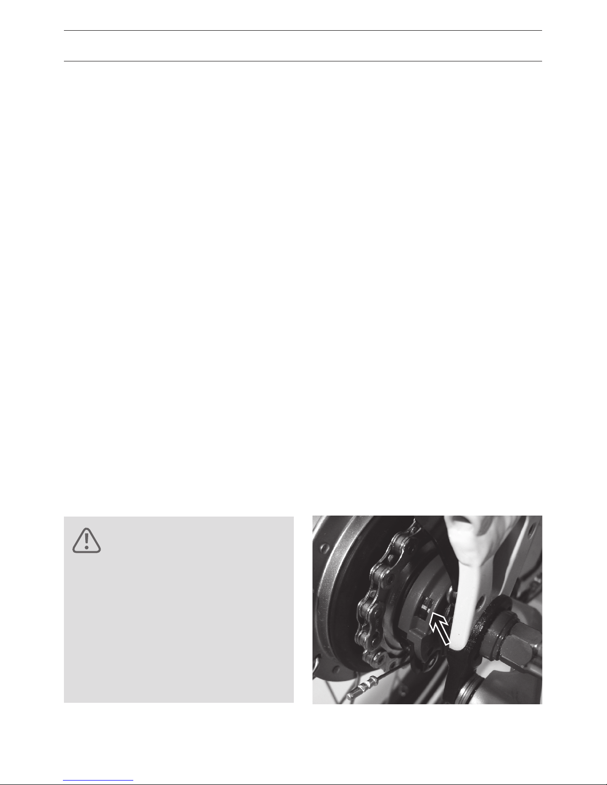
SHIMANO IGH
• Shift into first gear.
• Loosen the axle nuts.
• Take the rear wheel out.
• Rotate the fixing ring F counter-clockwise
and remove the shifting arm G from the
axle.
INTERNALLY GEARED HUB WITH
COASTER BRAKE
The brake arm A which attaches to the frame
and supports the hub while under brake
torque. Loosen the screws B.
SRAM DUAL DRIVE SYSTEM
Before removing the rear wheel, the clickbox
must be removed.
• Press the black button D on the clickbox
and remove it.
• A push rod is inserted in the axle. Be sure
not to lose it.
• Note the position of the washers and axle
nuts.
A
B
D
G
F

55
• Remove the left slider A diagonally to the
rear top. The tube can be replaced through
the now resulted gap.
• Alternatively you can remove the rear
wheel and remove the Harmony shifting
box (see NuVinci manual). Then it is pos
sible to lift the chain from the rear sprocket.
For assembly please note exactly the same
position of the shifting box.
NUVINCI AND NUVINCI HARMONY SYSTEM
Please observe the instructions of the sepa
-
rately included NuVinci manual.
CHANGING THE WHEEL ON BIKES WITH
QUICKRELEASE
Open the quick-release lever as described on
page 18.
• To facilitate the removal, draw the derail
leur or chain tensioner back with your hand.
Lift the bike slightly from the ground and
gently press down on the rear wheel.
WHEEL REMOVAL AT AVENUE HARMONY
Instead of removing the rear wheel it is also
possible to do the following:
• Open the quick-release of the left brake
body.
• Lift the left sidewall of the tire over the rim
and pull out the tube.
• Loosen the left axle nut.
• Loosen both bolts of the left slider dropout.
A

56
REPAIRING A PUNCTURE
REMOVING TIRES
• Unscrew the valve cover and mounting
nuts and let all of the air out.
• Press the tire from the sidewall towards the
center of the rim. Do this over the entire
circumference to make removing the tire
easier.
• Insert the brake levers on the right and left
side of the valve at the lower edge of the
tire. Keep one lever in this position and pry
the rim bead over the sidewall with the
other lever.
• Now you can remove the tube. Make sure
the valve doesn’t get caught in the rim and
that the tube isn’t damaged.
CHECK TIRE AND APPLY PATCH
• Patch hole according to the instructions
from the patch manufacturer.
• If you have removed the tire, you should
also check the rim tape. It should sit evenly
and must not be cracked or damaged and
should cover all spoke holes. If you have
questions about your rim tape, please ask
your dealer.
MOUNTING TIRE
• Make sure when installing the tire that no
foreign matter such as dirt or sand gets
inside as this could damage the tube.
• Place the rim with a horn in the tire. Press
the tire sidewall completely over the rim.
This should be possible with every tire
without using a tool.
• Insert the valve in the valve hole in the rim.
• Inflate the tube lightly so that it assumes a
round shape. Insert it completely in the tire
being careful not to crease it.
Make sure not to damage the
tube with the levers.
ATTENTION!

57
• Begin the installation on the side opposite
of the valve. Press the tire on the rim mak
ing sure not to pinch the tube between the
rim and the tire. Push the tube repeatedly
into the interior of the tire.
• Work both sides evenly around the circum
ference of the wheel. Towards the end you
will need to press the tire down firmly. Pull
the already mounted portion deep into the
rim as this facilitates mounting the last few
centimeters.
• Check again to make sure the tube is well
seated and press the tire with your palm
over the rim bead. If this fails, you must use
tire levers. Make sure that the dull side is
facing the tube so as not to damage it.
• Press the valve into the interior of the tire
so that the tube is not pinched between
the tire and rim.
• Is the valve facing straight up? If it is not
remove one side of the tire and readjust
the tube. If you want to make sure that the
tube is not crushed under the edge, you
should halfway inflate the tire and roll it
back and forth around the circumference of
the wheel.
• Pump up the tire to the desired pressure.
The maximum pressure is indicated on the
sidewall of the tire.
• Check the fit of the tire specifically the wire
(or Kevlar) bead against the sidewall of the
rim. The important thing is that the whole
tire has a uniform distance from the rim.

58
REPAIRING A PUNCTURE
FITTING CHAIN AND INSTALLING WHEEL
• On bikes with derailleur or chain tensioner,
pull it backwards and set the chain to the
smallest sprocket.
• Insert the rear wheel into the dropouts.
• At E-bikes with enclosed drive you must
place the rear wheel as shown and set the
chain onto the sprocket.
REINSTALLING THE WHEEL
The following section covers the reinstalla
tion of wheels in all Riese & Müller E-bikes.
Please read the entire section dealing with
your specific bike. Essentially the installation
process is the reverse of the removal.
CASSETTE JOINT FIXING RING
For bicycles with Shimano gear hubs, the
shift ring must in place before the rear wheel
can be reinstalled. The mounting ring must
be locked by rotating clockwise. Note the po
sition of the colored dots and that the shifter
is in the in the first gear.
Source: Shimano techdocs
For assembling align the
yellow marks •
Cassette joint fixing ring
Cassette joint

59
• Take care that the shifting arm point front
up. Insert the rear wheel into the dropouts.
Take care of correct position of the chain on
chainwheel and sprocket.
• Insert the rear wheel into the dropouts.
Take care of correct position of the chain on
chainwheel and sprocket.
POSITION OF THE WHEEL AND
CHAIN TENSION
• Check that the wheel is centered and if the
chain tension is sucient. More details on
the chain tension can be found on page
44 – 45 .
• Make sure that the chain is correctly placed
on the front chainwheel. Please refer to
pag e 44 – 45 .
TIGHTENING THE WHEEL ATTACHMENT
• Tighten the axle nuts or the quick release
to the specified torque settings (refer to
page 77).
• On bikes with coaster brakes, tighten
the brake arm attachment to a
torque of 4– 6 Nm.
CHECK BRAKE FUNCTION
• Hang the brake cable again.
• Check that the cable housing on rim or disc
brakes is still correctly positioned.
• After assembly check whether the brake
surfaces are free of grease and lubricants.
CHECK SHIFTING SYSTEM
Check the function of the shifting system.
ROHLOFF HUB
On bikes with a Rohlo hub, mount the shift
cables (see instructions in Rohlo manual).
NUVINCI UND NUVINCI HARMONYSYSTEM
Please observe the instructions of the
separately included NuVinci manual.
Incorrect installation can lead to
functional disruptions or failures
in the shifting or braking systems. After installing your wheel,
thoroughly check the shifting
and braking system!
DANGER!
60
HEADSET
FUNCTION OF THE HEADSET
The fork, stem, handlebars and front wheel
are able to rotate because of the headset
bearings. The headset must always move
easily. Large bumps or other changes can
cause the headset to loosen and develop
play.
CONTROLLING PLAY IN STEERING BEARINGS
• Apply the front brake and place the thumb
and forefinger of the other hand on the
upper steering bearing. Rock the bike for
ward and backward to check for play in the
bearings.
• If you can feel the upper bearing shell
moving when the bike is rocked, then it
needs to be tightened.
ATTENTION!
Setting the headset requires certain
expertise. Therefore it is best to
leave this work to your dealer.
DANGER!
Riding the bike when there is
play in the headset bearings
exposes the bearing and fork to
extremely high loads which can
lead to serious damage including
fork breakage!
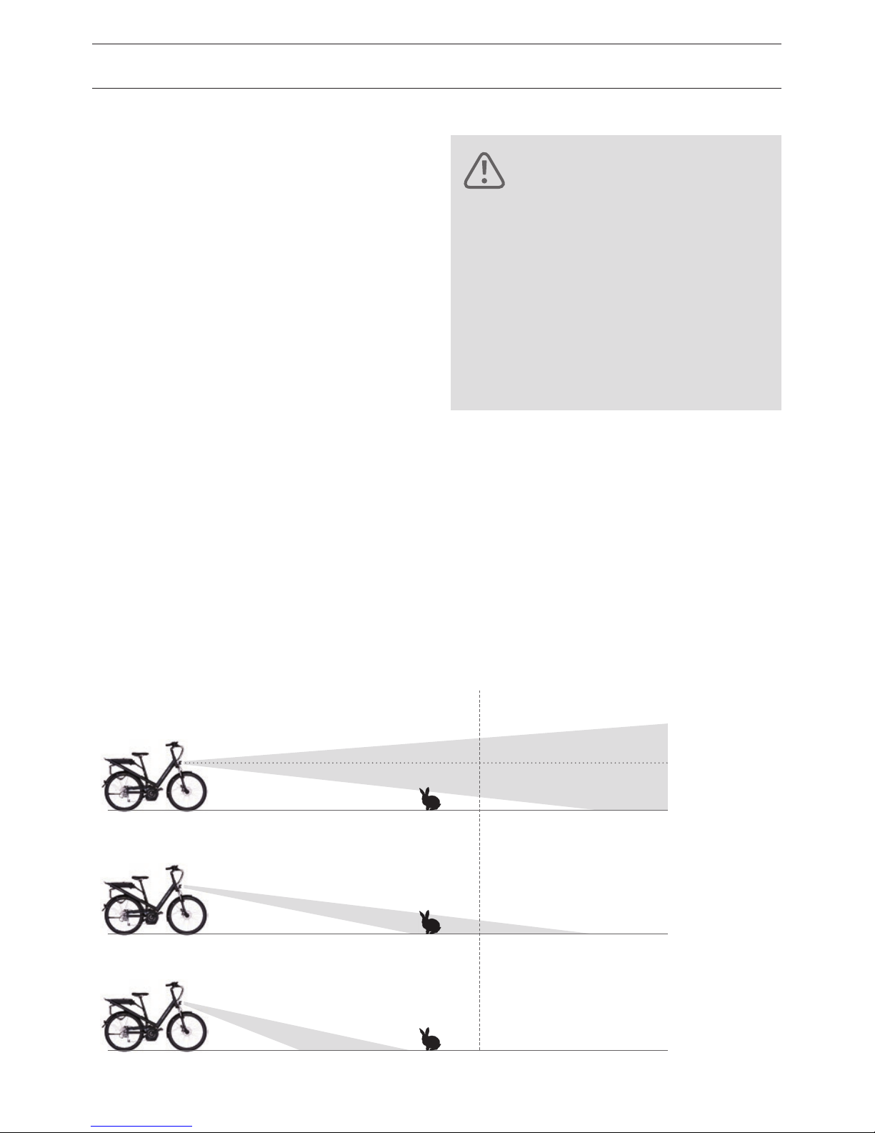
DANGER!
Never use your E-bike without
working lights! At night it is very
dicult to see obstacles and to
be seen by other road users.
Serious accidents can result!
An incomplete or malfunctioning
lighting system is not only illegal
but also endangers your life.
The light at all Riese & Müller E-bikes is
switched on and o at the Bosch display.
At HS-models the light is automatically
switched on.
LOCATING DEFECTS
Visually inspect the entire length of the wire
for damage. Verify all of the contact points
are intact. Often connections are corroded
by salt water or rain. Unplug the power cord
and plug it back together.
HEADLIGHT ADJUSTMENT
• The center of the front light’s beam should
have half the height at 5 meters in front of
the bike.
• The center of the front light’s beam should
hit the road at a maximum of 10 meters in
front of the bike.
• For correction of the adjustment loosen the
mounting screw and tilt the front light as
desired. Tighten the screw.
LIGHTING SYSTEM
61
10 m
WRONG
WRONG
OK.

62
LUGGAGE AND CHILDREN TRANSPORT
CARRIER FOR RACKTIME SNAPIT SYSTEM
The models Avenue, Culture, Delite,
Homage, Kendu and all blueLABEL models
allow to use Racktime snap-it products
(see www.racktime.com). This makes it easy
to fix baskets or child seats. But please note
the max. load (see page 77).
CARRYING CHILDREN AND LUGGAGE
Before you start to ride with your loaded
E-bike, please check the following points:
• Is the basket or child seat secured correctly?
• Is the child fastened or is the luggage
secured?
• Is the maximum gross weight not
exceeded?
• Does the child wear a helmet? Do you wear
a helmet?
• Does nothing can get caught by the wheel/
spokes?
• Is the tire pressure high enough?
Otherwise there is a risk of a puncture.
DANGER!
Do not ride your E-bike if
concerned about any of these
points. Basket or child seat can
loosen if not xed securely and
may cause heavy accidents!
DANGER!
Child seats are not allowed to
be mounted at the seatpost. You
must prevent that a child can
put his ngers between movable
parts of the saddle and the seatpost. This could cause serious
injuries. Only use approved and
secure child seats. Prevent that
the child’s feet can get caught by
the wheel/spokes.
When riding with a full load, the
handling is affected and it takes
longer to stop. Be sure to make
some handling and braking test
prior to heading into trac.
ATTENTION!
Do not leave your child in the
childseat when the E-bike stands
on the kickstand. The bike could
fall down and cause injuries.
ATTENTION!

63
INTEGRATED LOCK
TIP!
At page 12 you can see which
Riese & Müller models
can be tted with a child seat.
The models Avenue and Culture have a lock
which is integrated at the left side of the
frame. The key is used both for the integrat
-
ed lock and the battery lock.
Pull the cable out of the frame (wrap it
around a fence or a post) and push the cable
end into the lock.
ATTENTION!
Using a child seat on a fast E-bike
is allowed but transporting
children in trailers is not.
ATTENTION!
In Germany only children until 7
years are allowed to be transported in child seats. The driver must
be at least 16 years old.

64
KICKSTANDS
MOUNTING KICKSTAND
Almost all Riese & Müller E-bikes are fitted
with a rear kickstand which is attached di
rectly to the left dropout. Regularly check to
see if these screws are tight.
KICKSTANDS AT HS MODELS
According to StVZO the Riese & Müller and
blueLABEL HS models are fitted with an
automatic folding kickstand. Please notice
that a HS model can fall over and may get
damaged or damage other vehicles.
ATTENTION!
A loose screw may result in damage
to the kickstand mount!
PEDALS
INSTALLATION OF PEDALS
Grease the pedal threads before installa
tion and screw in the right pedal by hand
CLOCKWISE 2 – 3 rotations. The right pedal
is stamped “R”. Screw in the left pedal in by
hand COUNTERCLOCKWISE 2 – 3 rotations.
The left pedal is stamped “L”.
Tighten the pedals to a torque of 35 Nm
using a torque wrench.
The stamp is located either directly
adjacent to the threads or on the
top side of the pedal body.
ATTENTION!

65
The frame of the Load hybrid is separable
into front and rear halves to allow for easier
transport and storage.
• Lower the main kickstand.
• Open the two clamping screws on the left
brake lever and remove the brake lever
from the handlebar. Disconnect the head
light wire at the connector located under
the cargo area.
• Loosen the screws P on the steering link
age and pull the endpiece out of the
steering rod. Attach the steering linkage
(eg. with a cable tie) to the front frame.
• Remove the four screws S. It is helpful to
have a second person hold the rear of the
frame so that it cannot fall down. The front
frame remains standing on the front wheel
and kickstand.
• Reassemble in reverse order. Use new
thread adhesive (medium strength) and use
the recommended torque setting. Perform
a functional check of the brakes, lights and
steering. If necessary, the steering linkage
may have to be readjusted.
S
S
LOAD SEPARATING THE FRAME
P

66
BOSCH DRIVE
All Riese & Müller and blueLABEL models
are fitted with a Bosch drive. All you need
to know is to find inside the separately
attached Bosch manual. Carefully read the
information about battery and charger
handling.
If your E-bike has a drive with a performance
of max. 250 watts and the electrical as
sistance is limited to 25 km/h, you have an
license-free E-bike. The legal requirements at
page 8 apply.
The HS-models do not belong to the bicycles
category. Please read the article “E-Bikes –
HS-models” at page 10 – 11.
ECDECLARATION OF CONFORMITY
The EC-declaration of conformity is attached
to the Bosch-manual of your bike. Please
keep it safe.
DANGER!
Your local dealer must maintain
your E-Bike on a regular base
for a correct and safe operation.
Immediately remove the battery
from the E-bike when you nd a
defect at the electric system and
contact your local dealer. Also
contact your local dealer for
questions, problems or defects.
Lack of technical knowledge
may lead to serious accidents.
DANGER!
Remove the battery before you
transport or start to work on
your E-Bike. An unintended activation of the E-Bike drive can
lead to injuries.
TIP!
Please note that your E-Bike has no
light when the battery is removed or
the E-Bike system is shut down.

67
DANGER!
For your safety the charger
must be located on a dry and
non-ammable underground.
DANGER!
Never send a battery byself!
Batteries belong to the category
hazardous material. Under several circumstances the battery
can get hot and on re.
DANGER!
A defective battery may not be
charged or used. The battery
can get warm while charging.
A temperature until 45°C is allowed. If the temperature gets
higher you must end the charging process immediately.
ATTENTION!
Carefully read the manual of battery
and charger before you start to charge
the battery. Only use the original
charger. Disconnect battery and
charger from the power supply system
when the charge process is complete.
Do not open the battery. There is a
risk of short-circuit. It also voids
your warranty.
Protect the battery from heat, permanent sunlight, re and immersion
in water. This may cause danger of
explosion.
Batteries must not be exposed to
mechanical damage. Damage and
improper use may cause escape of
vapours.
Keep children away from the battery.
ATTENTION!

68
The electrical components of our E-bikes are
designed to operate down to a temperature
-10 °C with no problems. You just need to be
aware of a few things regarding using bat
-
teries in cold weather.
The energy content of a battery is always
listed at a certain temperature. In this case it
is stated at room temperature (23 °C). At this
temperature and above you can use 100 % of
the stated capacity of your battery.
In cold weather, the internal resistance
increases causing the energy content of your
battery to drop. You’ll notice a shorter range
on E-bikes in the winter. This is a normal
physical process and does not indicate errors
or defects. If you use your battery again
when it gets warmer, you can again use the
battery’s full energy content.
At temperatures of 10 °C this eect is very
low with the loss being in the single digits
and you will hardly notice the reduction.
With further decreasing temperatures, this
eect increases disproportionately.
In the extreme case of -10 °C you will only be
able to use approximately 70 % of the stated
battery capacity.
On cold days we recommend you store/
charge the battery overnight at room
temperature and then install the battery
on the bike just before driving o. It is also
important to draw some current from the
battery by using the motor support because
the drawing of energy warms the battery.
This should allow you to achieve the optimal
range of your E-bike.
It’s also a good idea to plan a shorter route in
the winter or use a lower level of support so
you are not surprised by a dead battery.
TIP!
Instruction for wintering your E-Bike:
charge the battery until 60 % of it’s
capacity. Recharge it every three
months until 60 % of it’s capacity.
EBIKES RANGE IN COLD WEATHER
DANGER!
Please note that condensation
can occur at the battery after
a sudden temperature change
from warm to cold. Avoid this
by charging and storing the battery at the same place. Use the
original charger only to avoid
the risk of re.

69
EBIKES HS MODELS
This section discusses the features and facts
for easy startup of your Riese & Müller HS
model (HS = High Speed). These fast E-bikes
will support up to 45 km/h and have a maxi
-
mum performance of 500 Watts.
Read more on legal requirements at page 11.
MOVING QUICKLY
If you want to ride as fast as a motorcycle
(35 – 45 km/h), you must honor all trac
rules to protect you and other road users.
Please occupy the center of the lane.
Do not worry about impeding trac as faster
vehicles will go around you. Riding in the
middle provides you with a buer zone from
the parked cars as well as makes you more
visible to other road users. Moreover we
also recommend that you ride with the light
on during the day so you can be more easily
seen.

70
TRANSPORTING THE EBIKE
LOCKING YOUR EBIKE
In recent years, the German Railway and
other international railway companies have
expanded the opportunities for bicycle
transportation so that bicycles can be
easily brought along. Be sure to inquire
about advanced booking or other formali
ties, especially in summer when the E-bike
compartments are often full. We recommend
removing all panniers and accessories prior
to locking the bike in the compartment to
prevent damage and theft.
TRANSPORTING ON A PLANE
E-bikes cannot be transported in the aircraft.
Li-Ion batteries of the size that we use are
considered hazardous goods and cannot be
transported in aircraft.
TRANSPORTING ON AN AUTOMOBILE
ROOF RACK
All E-bikes from Riese & Müller can be easily
transported using roof and luggage racks
from Thule and Altera. These systems allow
the easy mounting of the bike. Of course
there are other systems capable of carrying
our bikes but this is simply our recommenda
tion. If interested in another system, please
visit your local dealer for more informa
tion regarding compatibility. Make sure to
conduct a test to see if the rack can accom
modate the oversized frame tubes. We also
recommend driving more slowly and cau
tiously while the bike is attached to the car
and don’t forget about the bike on the roof
when you pull into a garage!
TIP!
For safety reasons you have to remove the battery and transport it in
the car. Moreover this decreases the
E-bike weight and makes handling
easier. Some carrier systems have
a load limit of 25 kg which you can
fulll by removing the battery.

71
TRANSPORTING IN A CAR
Whether you can transport the E-bike in
a car depends on the size of the car.
Riese & Müller E-bikes, despite their full
suspension systems, are no larger than con
ventional bicycles. To make it a little easier,
we recommend turning the handlebar and
removing the saddle, pedals and wheels.
Your Riese & Müller E-bike is relatively port
able and fits in most cars. Disassembly and
packing the E-bike gets easier once you are
familiar with the task.
TRANSPORTING ON AN AUTOMOBILE
REAR RACK
The choice of a rear rack is primarily de
termined by the type of car. Therefore we
cannot make any specific recommendations
and we suggest you contact the car manu
facturer and your local bike dealer for more
information.
Attention! Some bike rack clamps can dam
age the frame tubes. If in doubt consult your
dealer.
BIKES WITH DISC BRAKES
Please review the notes regarding the
removal of the wheels on page 35.
ATTENTION!
Some bike rack clamps can damage the frame tubes. If in doubt
consult your dealer.

72
ROUTINE MAINTENANCE
The E-bike you have purchased is a very high
quality product. When you pick the E-bike
up from the dealer, he has already made
the E-bike ready for you to ride. Neverthe
less the E-bike does require some routine
maintenance which is best performed by
your dealer. Only then can the safe operation
of all parts be guaranteed. This will keep you
riding happily and safely for many years.
WASHING AND CARING FOR YOUR EBIKE
Dried sweat, dirt and salt from winter riding
or from sea air can harm your E-bike. There
fore we recommend regularly cleaning and
corrosion protection of all susceptible bike
components.
The easiest way to remove dirt and salt is
using a pressure washer but this method has
serious disadvantages, the high pressure
stream of water can push past the seals and
into the interior of the bearings. This dilutes
the lubrication which increases friction that
ultimately destroys the bearing surfaces and
the smooth functioning of the bearing. Also,
decals are often accidentally blown o by
the powerful stream.
ATTENTION!
At fast E-bikes only some components can be replaced by different
components. You may risk the loss
of license and assurance for your
fast E-bike. Read more on page x.
ATTENTION!
Only perform maintenance tasks
for which you have the appropriate tools and expertise.
TIP!
Note that some cleaning products
may detach frame decals.
DANGER!
Shut off the E-bike drive and
remove the battery before you
start to work at your E-bike.
Unintended activation of the
E-bike drive can lead to injuries.
ATTENTION!
Do not clean your bike using a pres-
sure washer or steam cleaner at close
range. A much more gentle way to
wash the bike is with a gentle spray
of water or a bucket of water and a
sponge/brush.
As part of this regular maintenance,
you should check tire pressure, light
and brake functions and examine the
bike for damage.
GENERAL CARE / INSPECTIONS

73
DANGER!
As part of this regular maintenance, you
should check tire pressure, light and brake
functions and examine the bike for damage.
PROTECTING THE FINISH
After the E-bike is dried, you should protect
the paint and metallic surfaces with a hard
wax. Also protect spokes, hubs bolts and
nuts, etc. with a wax film. Polish the waxed
surfaces with a soft cloth so that they shine
and repel water.
CARING FOR ANODIZED SURFACES
The aluminum parts of your Riese & Müller
E-bike are protected by a special anodizing
process during which an electrochemical pro
cess generates a special protective layer. This
layer is very hard and therefore relatively
resistant to scratches. Despite the positive
attributes the anodized coating requires
care. Clean with water and if necessary use
mild detergents to dissolve grease. Dry and
apply a special anodized surface treatment
(available from your local dealer) with a soft
cloth which helps remove paint, tar and oil
residue. Lastly rub the parts with a soft,
clean cloth to remove excess treatment and
repel dust.
ATTENTION!
While cleaning look for cracks,
scratches, dints, or discolorations.
If in doubt, contact your local
dealer and let them replace
damaged components and touch
up damaged paint.
TIP!
Protect all places where cables
may rub the frame.
TIP!
After cleaning it is recommended
to lubricate the chain if necessary
(see page 38).
Ensure no lubricant or wax
contaminates the braking
surfaces of the disc brakes!
Imminent brake failure could
cause an accident!

74
GENERAL CARE / INSPECTIONS
STORING YOUR EBIKE
If you regularly maintained your bike during
the season, you won’t need to perform any
special preparations to store it on a short
term basis. It is recommended to store the
bike in a dry, well-ventilated area.
OVERWINTERING YOUR EBIKE
When storing your bike for the winter, there
are some things to consider:
• During extended storage the tires may
gradually lose air. If the tire remains flat for
an extended period, it could damage it.
• Clean the bike and protect it against corro
-
sion as previously described.
• Store the bike in a dry place.
• Switch the derailleur to the smallest
sprocket so the cables and springs are as
relaxed as possible. For Shimano hub gears,
shift to the first gear.
TIP!
TIP!
In the winter months when most
bike dealers aren’t very busy, many
shops offer special priced annual
checks. Take advantage of these
seasonal offers and bring your
E-bike to the dealer for inspection.
Instruction for wintering your
E-Bike: charge the battery until
60 % of it’s capacity. Recharge it
every three months until 60 %
of it’s capacity.

75
INSPECTIONS
A regular check of the bike guarantees long
term function and enjoyment. As with a car,
annual inspections can help prevent costly
repairs. The adjustment of the bearings or
shifting system and the timely exchange of
worn parts can prevent severe damage to
the operating parts of the bicycle. After the
initial break-in period, you should have your
E-bike inspected at regular intervals.
The recommended service intervals listed
in the table in the appendix (page x) are
intended for riders who ride between 1,000
and 2,000 miles per year. When riding more
or on poor roads/o-road, these intervals
are shortened. This also applies to taking
frequent trips in the rain or in a generally
humid climate.
DISPOSAL/ENVIRONMENTAL TIPS
Care products/detergents
Protect the environment while maintain
ing and cleaning your E-bike. Preferably use
biodegradable products. Detergents should
not enter drains. Used chemicals must be
disposed properly at the respective disposal
site.
Brake cleaner and lubricants
Please read the notes of the manufacturer of
these products.
Tires and tubes
Tires and tubes are no usual waste and
should be sorted for environmental-friendly
recycling.
E-Bike batteries
E-bike batteries are no usual waste. Please
return batteries that are no longer usable to
an authorized bicycle dealer..
ATTENTION!
After 200 – 400 km, but no later than
three months, bring your E-bike back
to the dealer for an initial inspection.

76
WARRANTY / GUARANTEE
Your dealer is legally required to provide an
E-bike that is not defective, of reduced value
or suitability. Your right to claims ends after
two years from the date you accept delivery
of the bike from the dealer. Notwithstanding
the statutory warranty of quality, we also
provide you a five year warranty against
frame or swingarm breakage.
Extended warranty claims are only valid if
the following conditions are met:
• You are the original owner of the E-bike
• Within four weeks of your purchase, you
have registered your bike in our online
system: www.en.r-m.de/registration
• The service record in the appendix is
completed and all required inspections
were performed and noted by the dealer.
In case of damage, the completed service
record must be submitted along with the
frame or the complete E-bike. Therefore pro
tect these important documents. If all criteria
are met, then we will replace the defective
item but shipping and labor will be charged
to the customer. This warranty only applies
to the original buyer. Further claims such as
damages or other losses are not covered.
Any warranty claims do not extend the origi
nal warranty period.
Damages due to wear and tear, neglect
(insucient maintenance), jumping, over
loading or amateur assembly or modifications (additions to or alterations of existing
components) are not covered.
Damages caused by competitive racing,
jumping or other types of overstressing are
not covered.
The battery of your E-bike is a consum
able item; the electronic components of
the system are subject to the two year
statutory warranty. We provide a voluntary
guarantee for the complete battery of one
year. We guarantee that the battery after a
year or 500 charge cycles (whichever comes
first) will still have a capacity of 60 %. Even
a “used” battery, which perhaps has only a
residual capacity of 55 %, can be used for
a long time with stable performance. The
battery should last over 1,000 charge cycles
without a problem.

77
INFORMATION REGARDING WEAR
Some parts of your E-bike are subject to
functional wear. The amount of wear de
pends on the maintenance of the E-bike and
the riding conditions (mileage, riding in the
rain, dirt, salt, etc.). Bicycles that are often
standing outside in the weather are subject
to increased wear. These parts require regu
lar maintenance and care but will (depending
on the intensity of use and riding conditions)
eventually reach the end of their useful life.
These parts must be replaced when they
reach there wear limit.
These include:
• chain
• brake cables
• grips
• chain ring and sprockets
• shift cables
• tires
• saddle cover
• brake pads
• rims
The pads or rim and disc brakes are subject
to functional wear. Sporty use or riding in
mountainous terrain shortens the life of the
pads. Check the pads regularly and replace
them as needed. You can acquire replace
ments from your local dealer. Rim brakes
not only wear out the pad but also the rim
itself. Therefore check the rim regularly such
as when inflating the tire. The sidewall of
the rim contains a groove that functions as a
wear indicator. When this groove is no longer
visible, the rim must be replaced. If deforma
tions or fissures in the rim sidewalls occur
when inflating the tire, the rim has reached
the end of its service life and needs to be
replaced.
Your dealer has performed the
nal assembly of the E-bike.
He has to perform a nal check
and a test ride.
ATTENTION!

78
WARRANTY / GUARANTEE
Also brake discs are subject to wear. During
inspection your dealer must check the disc
thickness and replace the disc if required.
The bearings and seals in suspension forks
and rear swingarms are always in motion
when the suspension is activated. Envi
ronmental conditions such as rain, dirt, etc.
cause these moving parts to wear out.
These areas must be cleaned and regularly
maintained. Depending on the operating
conditions it is possible that these parts may
need to be replaced due to wear such as the
development of bearing play.
Your point of contact for claims and services
is the dealer from which you purchased the
E-bike. Upon request we can refer you to
your nearest dealer (dealers can also be
found on our website www.r-m.de).
Additionally, we recommend that you contact your dealer to ensure the fastest and
most cost-eective solution. Please note
that if your E-bike is sent to us by your dealer
for repair: the E-bike must be suciently
clean before repairs can take place. Remove
any accessory items like computers, mirrors,
trailer hitches, locks, etc. prior to shipping.
Service is only performed on the original
standard equipment. Individual modifica
tions will be restored to the original standard
equipment. In the context of service no worn
out parts will be replaced and no inspections
carried out. In addition, payments and ma
terials are handled exclusively through our
dealers. Ensure that either you or your dealer
includes sucient postage.
To ensure a long service life the components
must be installed to the manufacture’s
recommended torque specifications and the
recommended service intervals must be
strictly adhered to. Failure to comply with
the installation requirements and inspection
intervals voids the warranty. Please note
that actions/inspections outlined in your
instruction manual may dictate the replace
ment of safety related components such as
handlebars, brakes, etc.
The actual standards and tests for E-bikes
define an average lifetime of 10 years or
16,500 up to 20,000 km (whichever occurs
first). Due to its high own quality standard,
Riese & Müller designs its products for a
triple lifetime of 60,000 km. But the stress to
an E-bike depends strongly on the load, the
road conditions and the riding style. Extraor
dinary stress (gross weight over 110 kg, bad
road conditions like cobble stones, potholes
or curbstones) will reduce the E-bike lifetime
to the normal Standard.
At the end of lifetime Riese & Müller does
not grant road safety.

79
WEIGHT RATING
MODEL WEIGHT
E-BIKE
MAX.
WEIGHT
RIDER
MAX.
LOAD
CARRIER
1
MAX.
LOAD
FRONT
CARRIER
GROSS
WEIGHT
Avenue 26,6 – 27,4 kg 110 kg 20 kg –– 140 kg
Culture 26,7 – 27,5 kg 110 kg 20 kg –– 140 kg
Delite 20,2 – 26,4 kg 110 kg 20 kg –– 140 kg
Homage 25,6 – 26,8 kg 110 kg 20 kg –– 140 kg
Kendu 25,8 – 25,9 kg 110 kg 20 kg –– 140 kg
Load 33,2 – 35,1 kg 120 kg
3
20 kg
3
100 kg 190/200 kg
2
blueLABEL charger 19,9 – 24,1 kg 110 kg 20 kg 130 kg
blueLABEL cruiser 24,8 – 25,8 kg 110 kg 30 kg 3 kg
4
130 kg
blueLABEL pony 21,9 23,8 kg 110 kg 20 kg –– 130 kg
blueLABEL swing 25,2 26,4 kg 110 kg 25 kg 3 kg
4
130 kg
blueLABEL wave 24,6 25,8 kg 110 kg 25 kg 3 kg
4
160 kg
1
Including weight of basket/child seat
2
First value is valid for HS model
3
Riders weight and luggage weight must not exceed 120 kg in total
4
Including weight of basket

80
RECOMMENDED TORQUE SETTINGS
* See the separate enclosed operating instructions of the component manufacturer.
PART FITTING TORQUE
Coaster brake arm Mounting screw 4–6 Nm
Brake lever Mounting screw 5–6 Nm
Shock Mounting screw 7–9 Nm
Freewheel Sprocket cluster lock ring 29–49 Nm
Delite carrier Mounting screw 8–10 Nm
Swingarm bushing Locking screw 5 Nm
Hydraulic brakes Mounting screw
Hydraulic brakes mounting screw
*
*
Crankset Crankbolts
Chainring bolts
35 Nm
8–11 Nm
Hub Quick release lever
Acorn nut for quick release
Axle nut for IGH:
· Shimano hub
· Rohlo hub
· SRAM Dual Drive hub
9–12 Nm
10–25 Nm
30–45 Nm
30–35 Nm
35 Nm
Pedals 35 Nm
Pletscher kickstand Mounting screw M6 12–14 Nm
Rohlo gears
*
Rear light Befestigungsschraube 3–4 Nm
Seat post Mounting screw for seatpost clamp
1/2 bolts
Clamping screw on seatpost
12–15/9–12 Nm
9–12 Nm
Shifter Shimano shifter
Twist grip shifter
4–6 Nm
1–2 Nm
Derailleur Mounting screws
Cable fixing screw
Guide pulley bolts
8–10 Nm
4–6 Nm
3– 4 Nm
Mudguards Mounting screw on frame front / rear 3– 4 Nm
Front derailleur Mounting screw
Cable fixing screw
5–7 Nm
4–6 Nm
V-Brake Mounting screw on frame socket
Cable fixing screw
5–9 Nm
6–8 Nm
A-Headset stem Handlebar clamp 2 / 4 screws
Stem clamp bolt
10 / 5,5 Nm
12–14 Nm

81
COMPONENT CONNECTION TORQUE
Frame Connection between the front and rear frames:
4 M10 screws
30–40 Nm
Fork Steerer tube clamp above the headset (2 screws)
Clamp on steering lever on right side of for tube:
4 M5 screws
Swivel head of the steering lever (M8)
12–14 Nm
5–6 Nm
12–14 Nm
Steering linkage Counter nut M8, swivel head on steering linkage
Front and rear end steering linkage: screw and M6 nut
Universal joint: screw and M8 nuts
9–12 Nm
9–12 Nm
12–14 Nm
Kickstand Counter nuts M8
Eye bolts and M5 nuts for kickstand spring
12–14 Nm
5–6 Nm
COMPONENT CONNECTION TORQUE
Stem Clamping screws M6 (4 pieces)
Front clamping screws M6 (2 pieces)
Rear clamping screws M5 (2 pieces)
Set screws for quick-release for
for angle adjustment (2 pieces)
7–9 Nm
7–9 Nm
3–4 Nm
1 Nm
LOAD: TORQUE SETTINGS
STEM AT KENDU/LOAD: TORQUE SETTINGS

82
SERVICE AND MAINTENANCE PLAN
PART TASK
BEFORE EVERY RIDE MONTHLY YEARLY SPECIAL INTERVALS
Lighting Check mounting screw
Tires Check air pressure
Check tread and sidewall
Brakes Check lever travel, pad thickness
and position on rim
Brake cables Visual check
Brake housing Inspect for leaks
Rear shock Maintenance (page 28), check function
Suspension fork Check for play and leaks, check function
Rims Check sidewall thickness /
wear indicator (possibly replace)
Rear swingarm Check function and bearing play
Chain (derailleur) Check chain tension, oil chain
Check wear, possibly replace
Chain (hub gear) Check chain tension, oil chain
Check wear, possibly replace
Crank Check, possibly retighten,
check chain ring wear
Paint Protect
Wheels/spokes
Check concentricity and tension
Handlebar / stem Visual check
Exchange
Headset Check bearing play
Relubricate
Metallic surfaces Protect (except rim sidewalls, discs)
Hubs Check for bearing play, lubricate
Pedals Check for bearing play, lubricate
Seat post Clean seat tube, lubricate
Derailleur Clean and oil
Quick release Check that it is properly seated
Nuts and bolts Check (possibly retighten)
Valves Check that it is properly seated
Housing shifter/brake Remove, lubricate and reinstall
Items marked with • can
be carried out by you as
long as you have the tech
nical skill and proper tools
such as a torque wrench.
If the inspection reveals
defects immediate action
is necessary. For questi
ons and concerns, please
contact your dealer.
Items marked with
✖
should only be carried out
by your local dealer during
the annual inspection.
TIP!
Always use original
or at least equivalent spare parts.

83
BEFORE EVERY RIDE MONTHLY YEARLY SPECIAL INTERVALS
•
•
•
•
•
•
•
Every 5,000 km
✖
Clean and lubricate monthly, see
guidlines of the manufacturer
✖ After the second set of brake
pads at the latest
✖
•
✖ From 1,500 km
•
Every 1,000 km
✖ From 3,000 km
✖
•
•
•
✖ After a crash, 20,000 km or
4 years – whichever takes
place first
•
✖
•
✖
✖
•
•
•
•
•
✖

84
DOCUMENTS
In the appendix of this manual you’ll find:
• the Riese & Müller service record which
should be filled out by your dealer after
each inspection/service. In case of a
warranty claim this record and a copy of
the proof of purchase must be submitted
to Riese & Müller. All of the service must be
completed by an authorized/ registered
dealer.
• a service and maintenance schedule can be
found on pages 80 – 82
• a list of torque settings for all of the criti
cal parts of your E-bike can be found on
page 78 – 79. The dealer requires these for
repairs and inspections.
Enclosed you’ll find
• the instruction manuals of various compo
nent manufacturers which contain detailed
information and instructions. There you
can also find details on use, maintenance
and care. Make sure to keep the instruction
manuals together with this manual.
• the instruction manual for E-bike technol
-
ogy.
• proof of purchase, which proves that you
are the first owner and how long you have
owned it.
We hope your E-bike will always provide a
good ride. Should any issue occur, please
contact your dealer for further assistance. In
case of additional problems that your dealer
cannot resolve, you can call us at any time.
YOUR RIESE & MÜLLER TEAM
ATTENTION!
As the rst owner of the E-bike
please ll in the service record in the
appendix and have all inspections/
service listed in there by an authorized/registered dealer.

85
SERVICE RECORD
Please have your authorized/registered dealer include all
inspections performed on your bike in this service record.
The extended warranty is only valid if you have registered
your bike within four weeks of the purchase, can provide a
completed service record (by authorized/registered dealers)
and proof of purchase.
Model:
Color:
Number of gears:
Frame number:
Battery number
Date of purchase:
THE TRANSFER WAS MADE:
City:
Date:
Dealer stamp:
Signature of dealer:

86
SERVICE RECORD
1st Inspection
Within 3 months of purchase
or within the first 400 km:
Replaced or repaired parts:
Order number: Date:
Stamp/Signature of dealer:
2nd Inspection
Within 1 year of purchase
or within the first 2,000 km:
Replaced or repaired parts:
Order number: Date:
Stamp/Signature of dealer:
3rd Inspection
Within 2 years of purchase
or within the first 4,000 km:
Replaced or repaired parts:
Order number: Date:
Stamp/Signature of dealer:

87
4th Inspection
Within 3 years of purchase
or within the first 6,000km:
Replaced or repaired parts:
Order number: Date:
Stamp/Signature of dealer:
5th Inspection
Within 4 year of purchase
or within the first 8,000 km:
Replaced or repaired parts:
Order number: Date:
Stamp/Signature of dealer:
6th Inspection
Within 5 years of purchase
or within the first 10,000 km:
Replaced or repaired parts:
Order number: Date:
Stamp/Signature of dealer:

NOTES

© 2015, Riese & Müller GmbH
Text and concept
Riese & Müller GmbH
Graphic design
www.wolf-corporate.de
Photography
Kay Tkatzik, Riese & Müller GmbH
State 03/2015
This instruction complies with the
requirements of the European
standard EN 15194

Riese & Müller GmbH
Feldstraße 16
64331 Weiterstadt
Germany
team@r-m.de
www.r-m.de
Tel.: +49 61 51-366 86-0
Fax: +49 61 51-366 86-20
Scan the QR code with your smartphone
to get direct access to all actual
instruction manuals. Or visit our website:
en.r-m.de/infocenter/downloads/
 Loading...