

Page 1

INSTRUCTION MANUAL
Birdy
Frog
Page 2
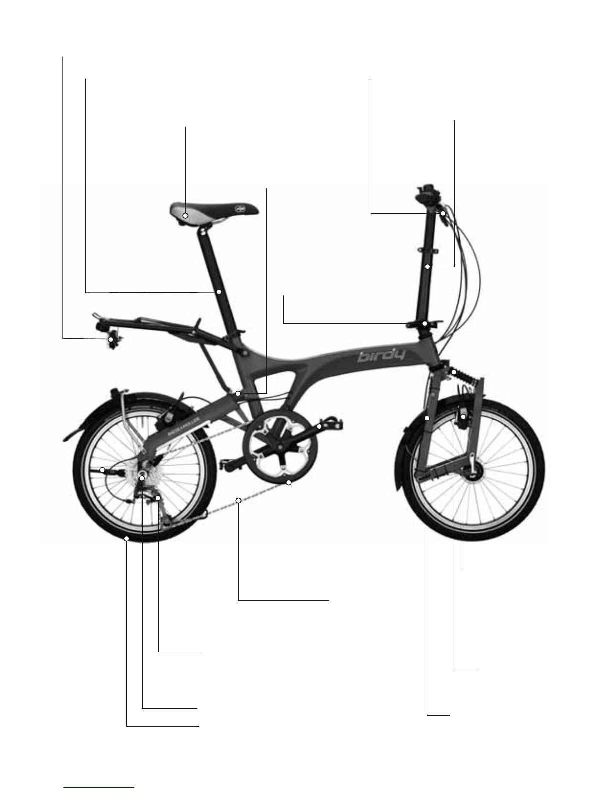
Shifting, p. 36
Derailleur, p. 38
Hub gear, p. 41
Wheel attachment, p. 46
Wheels and tires, p. 44
Brake lever, p. 19
Shifter, p. 37
Seatpost, p. 16
Stem, Handlebar, p. 18
Stem folding hinge, p. 24
Headset, p. 52
Lighting, p. 55
Suspension fork, p. 25
Front swingarm
catch, p. 54
Brakes
Rim brakes, p. 32
Disc brakes, p. 35
Chain, p. 43
Rear suspension, p. 21
Saddle, p. 18
Page 3

© 2013, riese und müller GmbH
Text and concept
riese und müller GmbH
Graphic Design
www.wolf-corporate.de
Photography
Kay Tkatzik, riese und müller GmbH
Torque settings in this manual
are specied in Nm. Do not rely
on your feeling: “tight” is simply not precise enough. ONLY a
torque wrench can ensure that
the bolt is properly tightened.
You should always use this tool
to tighten the components to the
specied torque setting. A bolt
that is too tight or too loose can
cause malfunctions which could
lead to an accident.
DANGER!
Page 4

Dear customer,
Congratulations on your new Riese & Müller bike. Thank you for choosing
us for your mobility needs. Riese & Müller builds lightweight and practical
bikes that are characterized by exceptional handling and award win-
ning design. Your dealer has performed the final assembly of the bike
and possibly implemented some requested changes for you. They have
performed a test ride to ensure an enjoyable riding experience from the
very start. During the design process, we constantly think about your
riding enjoyment and safety. Even though we cannot
anticipate every
possible scenario, this manual answers many of the key
questions you
may have and gives you many tips on using your bike.
Furthermore, a lot of interesting facts about bicycle technology, mainte-
nance and upkeep are summarized for you to ensure that you enjoy your
new Riese & Müller bike for many years for come. If after reading this
manual, you still have questions, please feel free to contact your dealer
or us directly. Since our bikes are constantly being updated and improved,
we may provide additional supplementary pages to ensure you have the
most up to date information. Please be mindful that some updated infor-
mation may have already been included with your new bike.
The Riese & Müller Team
Page 5

3
4 General information
6 Before the first ride
8 Before every ride
9 Legal requirements
10 Unfolding your Birdy
12 Folding your Birdy
14 Transporting your Birdy
16 Adjusting the riding position
20 Pedals
21 Adjusting the suspension
22 Quick release
24 Stem folding hinge
27 Front swingarm catch
28 Rear swingarm catch
30 Brakes
36 Shifting system
43 Chain
44 Wheels and tires
52 Function of the headset
54 Suspension pivot bearings
55 Lighting system
56 General care/Inspections
59 Warranty/Guarantee
62 Torque settings
64 Service and maintenance plan
66 Documents and service record
CONTENTS
Page 6
4
GENERAL INFORMATION
Riese & Müller bicycles are equipped with innovative technology. So please read this manual
even if you are an experienced cyclist.
To ensure you always have a fun and safe ride, you should perform the quick check before
every ride. For instructions on this quick check please see page 6.
In this manual, a number of maintenance and repair tasks are described in detail. If you
engage in this activity you must always consider that the instructions are exclusively for the
designated Riese & Müller bicycles and are not transferable to other bikes.
Through a variety of design and model changes it is possible that the included instructions are
not up to date. If necessary, review the separately attached instructions.
Note that the successful execution of the included instructions may require special tools or
technical expertise. If you are uncomfortable performing any of the listed tasks, please seek
the assistance of a professional.
If you reach a certain point where you are not sure how to proceed, please contact your local
dealer or us directly. We are happy to help!
The following are a few things that we cyclists hold very dear. Always take care in trac as
not to endanger yourself or others. Respect the rules of the road so you don’t draw the ire of
other road users. If you tour through forests and meadows, please respect nature by cycling
only on marked or paved roadways. Observe the legal requirements for the o-road use of bi-
cycles, which are available from your local authorities. Never ride without a helmet and make
sure you always wear appropriate clothing.
We hope you enjoy your new Birdy!
Do not ride if the test wasn’t passed with 100% certainty.
DANGER!
Page 7
5
We’ll begin by telling you about the parts of your Birdy. Open the front cover of this
brochure. Here you’ll find a Birdy with all of the relevant parts clearly shown.
Tip! Keep the front cover opened as this makes orientation easier!
We have tried to vividly portray all of the relevant information to ensure your satisfaction with
your new Riese & Müller bike. Therefore we use the following symbols:
Attention! Here is a hint that will help you quickly become familiar with your bike and its
technology.
Danger! This symbol indicates that life-threatening risks are possible if the correspond-
ing instructions are not followed. Please read carefully.
Tip! This symbol indicates useful additional information.
This manual covers the installation and maintenance work that may be best
performed by your local dealer (p. 62 - 63). Do not perform any task that you are
uncomfortable with. Many of these tasks require special knowledge and tools
and should only be performed by an expert. Never ride your bike with incomplete or improper maintenance. You could endanger your life or the lives of others.
DANGER!
Page 8
6
BEFORE THE FIRST RIDE
CARRIERS/TRAILER BIKES
Only two-wheel trailers with attachment at the rear axle are approved for use with the Birdy.
TRAILER HITCH
We recommend the “Weber-trailer hitch”.
INTENDED USE
Use the Birdy only on streets and surfaced roads. We can take no responsibility for the
consequences of inappropriate use, assembly errors, accidents, racing, jumping
or similar activities.
BIRDY GROSS VEHICLE WEIGHT RATING
(Birdy, rider and carrier load) 120 kg (265 lbs)
MAX. CARRIER WEIGHT RATING
Expedition carrier 15 kg (33 lbs)
Lowrider 10 kg (22 lbs)
SL carrier 12 kg (26 lbs)
Max. trailer weight rating (including carrier weight) 50 kg (110 lbs)
HEIGHT
The Birdy accommodates riders up to a height of 195cm.
Other trailer hitches do not guarantee perfect function of trailer and suspension
and could cause accidents or damage!
DANGER!
Page 9
7
CLOTHING
Wear bike appropriate clothes. Never ride without wearing a helmet!
BRAKES
Are you familiar with the braking system? Check to make sure that the front brake lever is on
the side of the handlebar that you are used to. If it isn’t then you can either train with the new
arrangement or have your dealer change the arrangement to fit your needs.
SHIFTING
Are you confident that you know how to change gears?
Conduct a test ride to familiarize yourself with the shifting system in a low-trac area. You
can read more about gearing systems on pages 36-42.
SEATING POSITION
Are the saddle and handlebar in the right position? Your dealer can assist you in finding the
best seating position. The saddle should be adjusted so that with the pedal in its lowest posi-
tion, you can just reach it with your heel. Check that you can stay in the saddle and still reach
the ground with your tiptoes. Your dealer will be able to help you if you’re not happy with your
saddle position. You can read more about seating position on pages 16-20.
SUSPENSION
Is the suspension adjusted to suit your needs? More information regarding suspension on
page 21.
Modern brakes are much more powerful than simple rim or drum brakes. Make
sure to rst test the braking power before heading into trac. Unintended braking can lead to an accident. Slowly squeeze the brake to generate more braking
force. You can read more about the braking system on pages 30-35.
DANGER!
Page 10

8
BEFORE EVERY RIDE
Before every journey you must check the following points:
Are the quick releases on the wheels, the stem and the seatpost clamp all correctly fastened?
Read more on pages 22 – 23 of this manual.
• Is the tension lever on the stem hinge closed correctly? Are all hinge parts for the stem hinge
present? More information on page 24 – 26.
• Is the quick release lever on the height adjustable stem closed?
• Is the pin of the height adjustable stem fully snapped into one of the holes.
Read more on page 18.
• Are the rear swingarm catch and the front swingarm catch both correctly engaged? More
about this on pages 27 – 29.
• Are the tires in good condition, are they running true and are they at the correct pressure?
More on this topic on pages 44 – 45.
• Perform a stationary brake test by pulling the levers hard towards the handlebar. The brake
pads should press with their full area against the rims, without touching the tire. You should
not be able to pull the lever right up to the handlebar! Further tips on braking on pages
30 – 35.
• Check that the dynamo is securely mounted. Does the light illuminate properly?
More on lighting on page 55.
• Is the max. load not exceeded (page 6)?
• As you ride, always listen out for unusual rattling noises or unusual handling – these could
indicate a problem. If this occurs, check bearings, pivots, all fasteners and parts of the folding
mechanism.
Do not ride the bike if your bike fails any of these checks! If in doubt, always
consult your dealer. A defective bike can lead to serious accidents!
DANGER!
Page 11

9
LEGAL REQUIREMENTS
When you ride your bike on the road, it must comply with trac laws and guidelines.
These will vary from country to country. In general, there are minimum standards for brakes,
reflectors and lighting systems, as well as usually a general responsibility to ensure that
your vehicle is in roadworthy and in safe condition. You also have a duty to ride in a safe and
responsible manner. If you ride your Birdy in trac, be sure to observe all relevant laws and
regulations. Please ask your local transportation administration for current information.
BRAKES
In most countries, including Germany and the UK, two independent brakes are
required. Do not ride with only one functioning brake!
LIGHTS
Bicycle lighting systems need to comply with the relevant national standards.
Page 12
10
UNFOLDING YOUR BIRDY
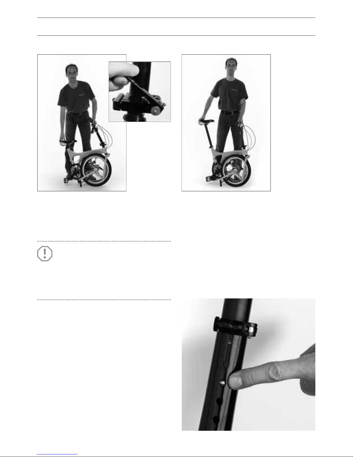
• Open the seatpost quick-release and raise
the seatpost to the appropriate height (no-
tice the height marks on the post).
• Close the quick-release again. Do not raise
the seatpost beyond the minimum inser-
tion mark (see page 15).
• If your Birdy is equipped with a height-ad-
justable stem, open the height-adjustment
quick-release, press the pin and raise the
stem to the desired height.
• Carefully close the quick-release.
• Check that everything is secure on the
stem, by holding the front wheel between
your legs and attempting to twist the han-
dlebar with your hands. If it doesn’t turn,
it’s secure.
01 02
05
• Unfold the stem and handlebars.
• Close the hinge lever.
ATTENTION!
Do not pull out the seat post above
the minimum insertion mark.
Please read page 23.
Page 13
11
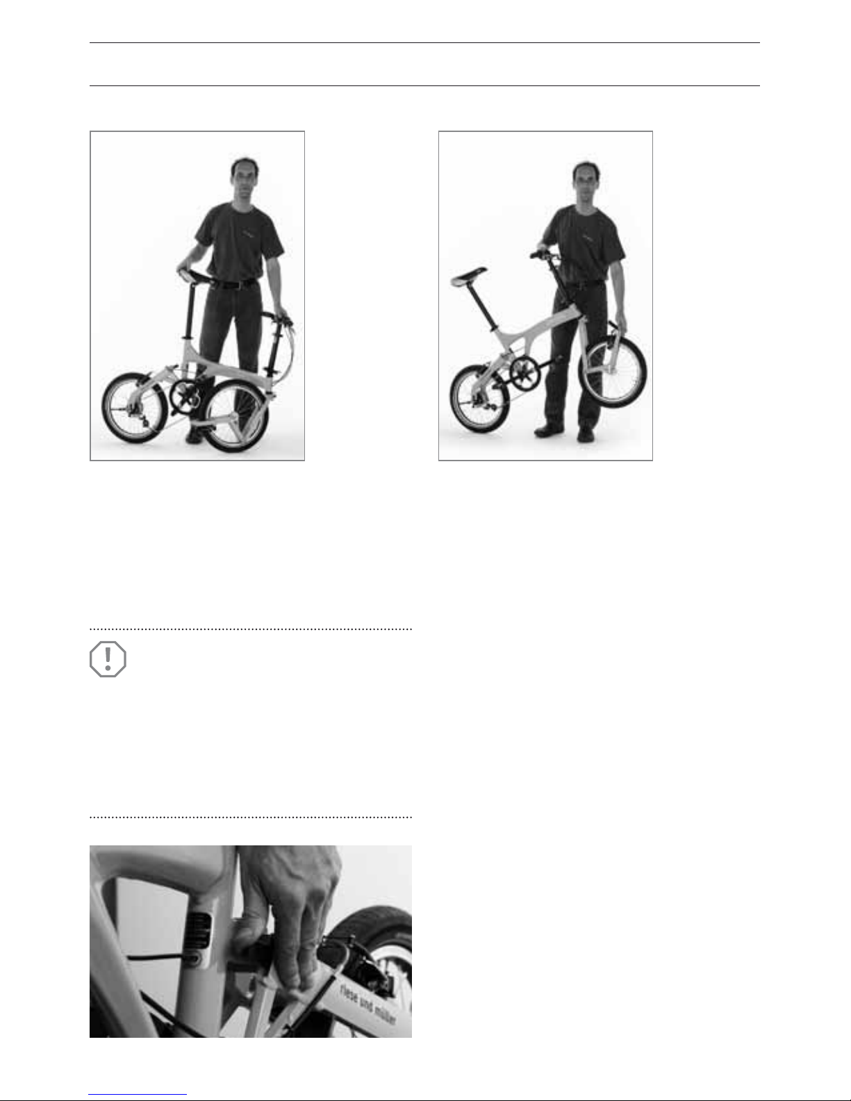
• Lift the Birdy by the handlebar, unfold the
front wheel and put the Birdy back on the
ground.
• Press briefly on the handlebar, so that the
front spring audibly engages in the front
swingarm catch.
• Adjust the seatpost to the correct height.
Turn the saddle so it is in line with the bike,
by lining up the front of the saddle with the
bottom bracket or along the main frame
tube.
• Check that the seatpost is securely xed
by grasping the front and rear of the sad-
dle and attempting to twist it. If it doesn’t
move at all, it’s secure.
04
06
03
• Lift the Birdy by the saddle, so that the rear
swingarm swings backwards.
• Engage the rear swingarm catch.
If you have one, unfold the kickstand.
ATTENTION!
Under no circumstances should
the stem be raised beyond the
‘MINIMUM INSERTION’ mark.
Check that the pin engages in one
of the holes at the stem.
Page 14

12
• Fold the front swingarm right under until
the front wheel rests next to the main
frame tube, and the tire grips up against
the fixing screw on the front forks.
• Put the bike back down. If you have one,
fold up the kickstand. Lift the bike a little
by the saddle and open the rear swingarm
catch with a light outward pull.
• Now fold the rear swingarm forward and
put the Birdy back on the ground.
• Now open the seatpost quick release and
lower the saddle as far down as it will go.
Close the quick release.
• Finally, open the stem hinge lever and fold
the handlebars down. Finished!
With a little practice you can easily fold the
Birdy very quickly. The folding procedure is
as follows:
• Select the highest gear – the chain should
be on the smallest sprocket.
• If your Birdy is equipped with a height-ad-
justable stem, open the height-adjustment
quick-release, press the pin and lower the
stem to the lowest pin hole. Close the quick
release again.
• Ensure the right-side pedal points up-
wards (the crank should be in line with
the seatpost).
• Stand on the left side of the Birdy and grip
the handlebar with your right hand. Press
the front swingarm catch with the left
hand, so that it releases the spring from the
fork.
FOLDING YOUR BIRDY
Page 15

13
BIRDY RACE
The drop bars on this model increase its
folded size. Depending on the setting of the
bar, the end of the bar can touch the brake
disc. This should be avoided as it can cause
brake pad deformation. Additionally the
stem should not be raised to the highest
position because this can place too much
pressure on the brake and shifting cables.
Prior to folding ensure that the chain is
on the largest chainring and the smallest
sprocket to ensure the chain does not jam
or fall o during folding.
TIP!
Do not store the Birdy Rohloff on its side for a long time. There
is the possibility of oil leakage from the Rohloff Speedhub. This is
technically harmless but should be remembered when storing the
Birdy in sensitive areas.
Page 16
14
Once folded, your Birdy is easily transport-
ed in the trunk of a car, on trains, buses,
ferries and airplanes.
TRAIN TRAVEL
Some train services require that your Birdy
is covered up in a bag, especially if it is
carried on as normal luggage, rather than
placed in the luggage car or designated
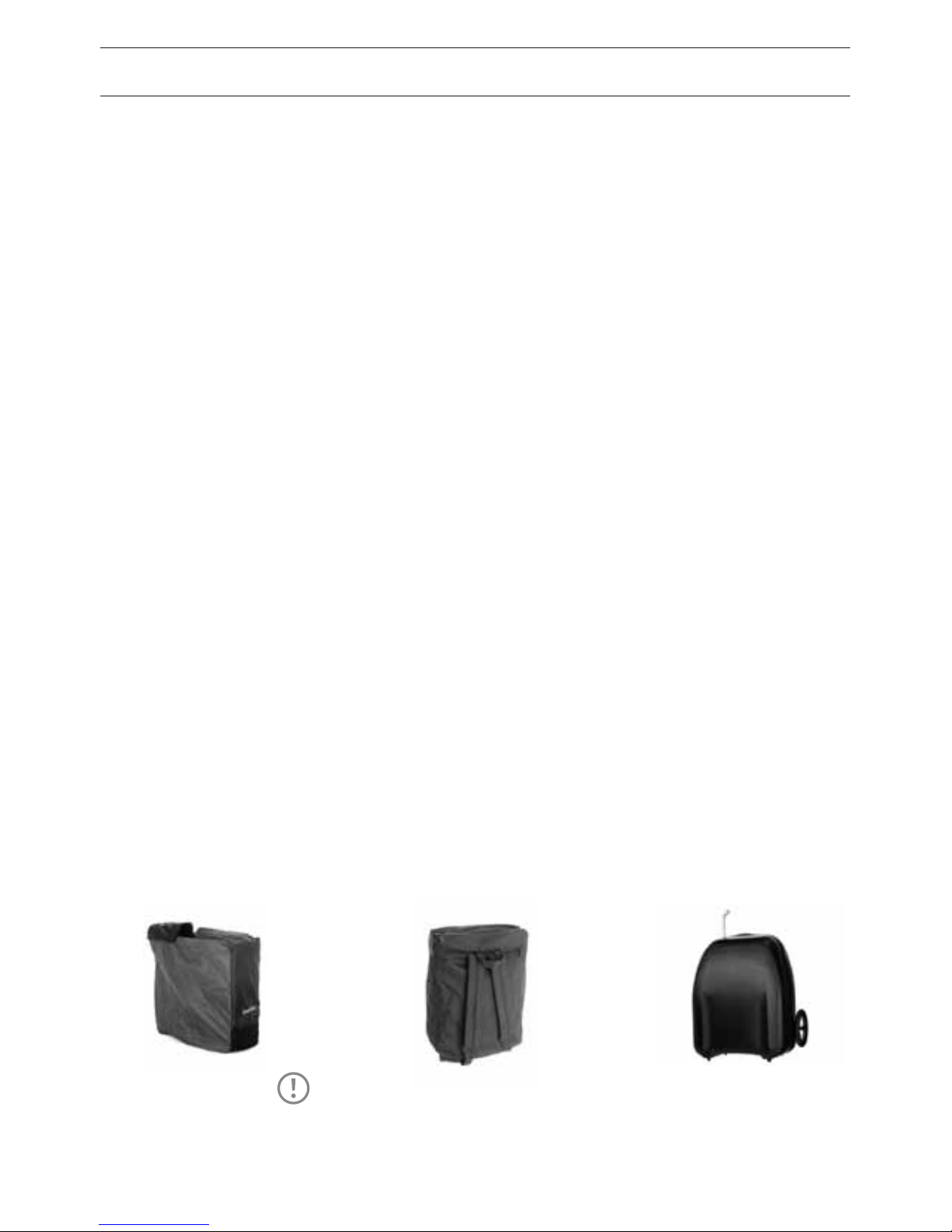
storage area. Two Birdy bags are available:
the protective cover and the rucksack bag.
The protective cover slides over the Birdy in
one easy motion, and is closed at the bot-
tom with a pull on the drawcord. The cover
is made from tear-resistant nylon. Like a
poncho, it folds up very small into its inte-
grated mesh pouch, and is then fastened to
the bike. The rucksack bag is an ideal Birdy
accessory. Two large compartments carry
all of your belongings. Open up another
zip and another compartment opens up to
allow you to stow your Birdy. The bike can
then be easily carried with the padded shoul-
der strap or the carry-handle. You can still use
the other luggage compartments. It’s made
from extremely durable Cordura Plus.
AIR TRAVEL
We recommend that when you take your
Birdy on a plane you package it in a strong
box – for example, the box in which it ar-
rived at your dealer. The pedals should be
removed and packaged separately. Another
possibility is the use of the rucksack bag –
we recommend that in this case you use
plenty of additional cardboard and bub-
blewrap to protect against bumps. The rear
derailleur is the most vulnerable part of
the bike: we recommend that you unscrew
it from the frame, wrap it in bubblewrap,
and tape it to the frame so that it won’t be
vulnerable to impacts.
The Birdy suitcase has two small wheels
and can be used like a trolley because of its
telescopic grip. Before putting the Birdy into
the suitcase the pedals must be removed.
Because of the many variations of the Birdy
accessories (fenders, kickstand, carriers,
lighting) is may be necessary to remove
some of them.
TRANSPORTING YOUR BIRDY
Backpack SuitcaseCover
TIP!
If the suitcase gets damaged during the ight please contact the
airlines baggage department immediately to le a damage claim.
Page 17

15
Page 18

16
ADJUSTING THE RIDING POSITION
HOW CAN I CHECK MY SEATING POSITION?
A good riding position is important for your
comfort and for optimal performance on the
bike. You need to adjust saddle and handle-
bars very precisely to ensure the best possi-
ble fit. Several components on the Birdy are
designed to adjust to suit your body dimen-
sions. If required, you dealer will be pleased
to change the stem on your Birdy.
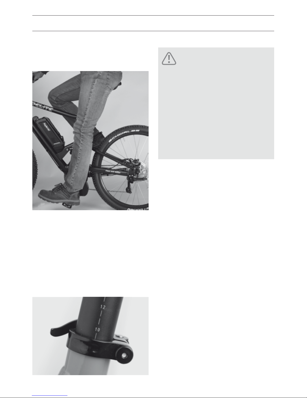
ADJUSTING FOR THE CORRECT SADDLE HEIGHT
The need for a comfortable pedaling action
determines the saddle height. It’s important
that when you pedal, the ball of the foot
should be over the center of the pedal axle.
When the pedal is at its lowest position your
leg should not be quite fully extended. If
the saddle is too high, it’s hard to get round
this lowest point, and the pedaling action
becomes uneven. If the saddle is too low,
you’re likely to experience knee pain.
Check the seat height using the following
simple procedure. Use shoes with a flat sole
for this check:
• Sit on the saddle and put your heel on the
pedal, so that it moves to its lowest posi-
tion. In this position the leg should be fully
extended. Note that the hips should stay
straight and level.
• To adjust the seat height, you need to undo
the quick-release.
• The loosened seatpost can now be adjust-
ed for height. Make sure that the seatpost
is not greased. If it doesn’t slide smoothly in
the frame, clean out and remove all grease
from inside the frame and on the seatpost.
If you have further problems, consult your
dealer. It should never require extreme
force to adjust the seatpost.
• Set the saddle straight, by lining up the
saddle nose either with the bottom bracket
or the main frame tube. Close the quick
release.
• Check that the seatpost is securely xed
by grasping the front and rear of the sad-
dle and attempting to twist it. If it doesn’t
move at all, it’s secure.
• Does the leg extension seem correct when
you repeat the test? Check it by moving
your foot to the ideal pedaling position,
with the ball of the foot above the pedal
axle. The knee should now be slightly bent
All of the procedures we are about
to describe require a certain
de-gree of skill, suitable tools and
mechanical aptitude. After any assembly or maintenance procedure,
perform the Quick Check (see page
8) and take a short test-ride some-
where quiet, away from trac.
This lets you check in safety that
everything works properly. If you
have any doubts, it’s best just to do
the riding position check, and then
to explain any changes you’d like
to your dealer. They can carry out
your requests with all the proper
tools and skills, perhaps in con-
junction with the rst inspection.
DANGER!
Page 19
17
– if this is so, you’ve reached the correct
saddle height.
• Check that you can stay in the saddle and
still reach the ground with your tiptoes. If
this isn’t the case, put the saddle a little
lower.
• Memorize the insertion mark on the
seatpost so that when later unfolding you
immediately know the correct height of the
seatpost.
BIRDY STEMS
Two dierent handlebar stems are available
for the Birdy:
• Sport stem, adjustable – allows sporty posi-
tion for riders of all sizes
• Comfort stem, adjustable – the handlebar
is closer to the saddle and allows a more
upright rider position
Your dealer can change the stem following
your needs.
Upright rider’s position
Advantage: lower load on the wrists, arms
and cervical spine.
Disadvantage: higher load on the saddle.
Sporty rider’s position
Advantage: less loads for the seating area,
more ecient performance, less air resist-
ance, more weight on the front wheel.
Disadvantage: higher loads for the wrists,
arms and cervical spine.
Do not ride if the seatpost is
withdrawn beyond the ‘MINI-
MUM INSERTION’ mark! This
mark must not be visible: if it
is, the seatpost could break or
the frame could be damaged.
The seatpost is not designed for
mounting bags or carriers on
the seatpost or the saddle. This
could overload of the seatpost!
DANGER!
Page 20
18
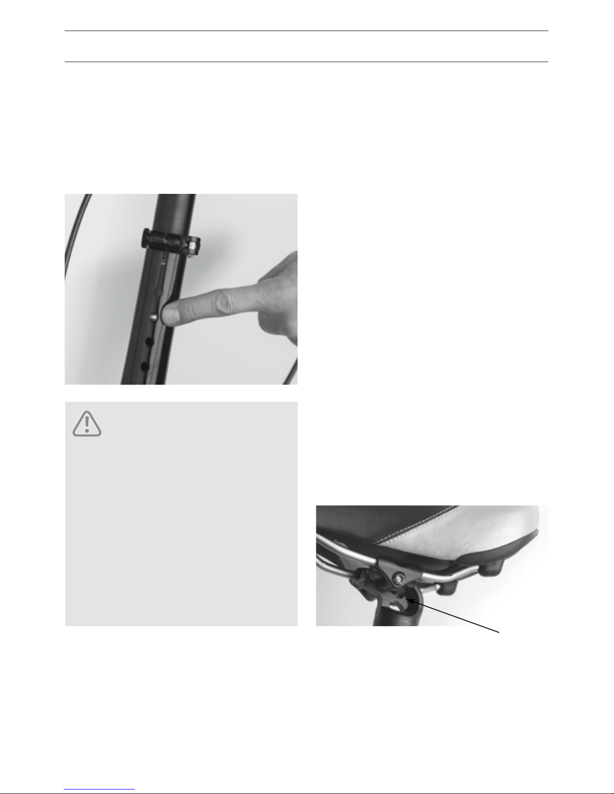
ADJUSTING THE HANDLEBARS
• Open the quick release at the stem.
• Press the pin and adjust the stem to the
desired height. The pin has to engage again
into one of the holes.
ADJUSTING THE RIDING POSITION
ADJUSTING REACH AND SETTING
THE SADDLE ANGLE
The distance between the handlebar grips
and the saddle (reach), and the angle of the
saddle, are important factors when it comes
to how much you’re leaning forwards, and
hence for your riding comfort and perfor-
mance. The reach can be adjusted over a
short distance using the saddle rails, by slid-
ing the saddle forward or backward on the
seatpost clamp. This will also aect pedaling:
if the saddle is all the way back, you’ll be
pedaling more “from behind”, and vice versa.
The geometry of the Birdy was designed so
that for normal use, the saddle is positioned
as far forwards as possible. This minimizes
folded size. The saddle should in general be
set dead level.
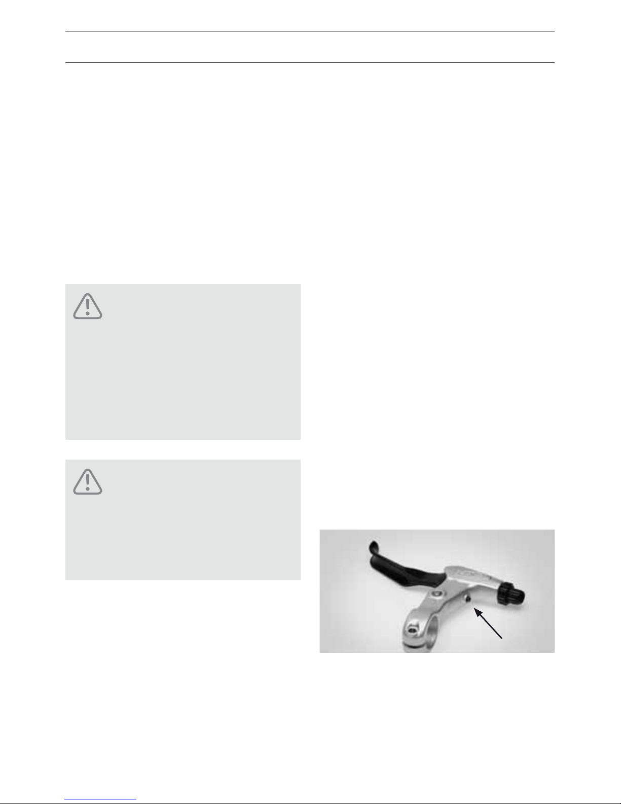
• Release seatpost clamp bolt A, turning at
most three or four turns anticlockwise.
No more, or the whole assembly can fall
apart.
Do not ride if the stem is ex-
tended beyond the ‘MINIMUM
INSERTION’ mark!
Do not ride if the quick release of
the adjustable stem is not tightened or the pin is not engaged in
one of the holes.
Never open the quick release
while riding!
DANGER!
A
Page 21
19
• Move the saddle forward or backward as
required. Often only a light bump to the
saddle is needed. Retighten the bolts, turn-
ing them clockwise.
• Adjust the saddle angle and tighten bolt A.
Observe the recommended torque setting
of 9-12 Nm.
• When you’ve tightened everything, check
whether the saddle tilts, by pushing alter-
nately on the front and back.
ADJUSTING THE REACH OF THE
BRAKE LEVERS
The distance between brake levers and
handlebar grips is adjustable. The levers
can be brought closer to the bars, mak-
ing them easier to use for riders with
small hands. The lever position where
the brakes start to “bite” also needs to be
adjusted for finger length.
• Check when the brake pads hit the rim. If
this “bite point” comes after just a short
movement of the levers, you’ll have to
adjust the cable in order to alter the lever
reach (see page 31). Otherwise, the brakes
may rub on the rims after the reach
adjustment. If, however, the brakes only
bite after the levers are halfway to the
bars, you have some “play” with which to
adjust lever reach.
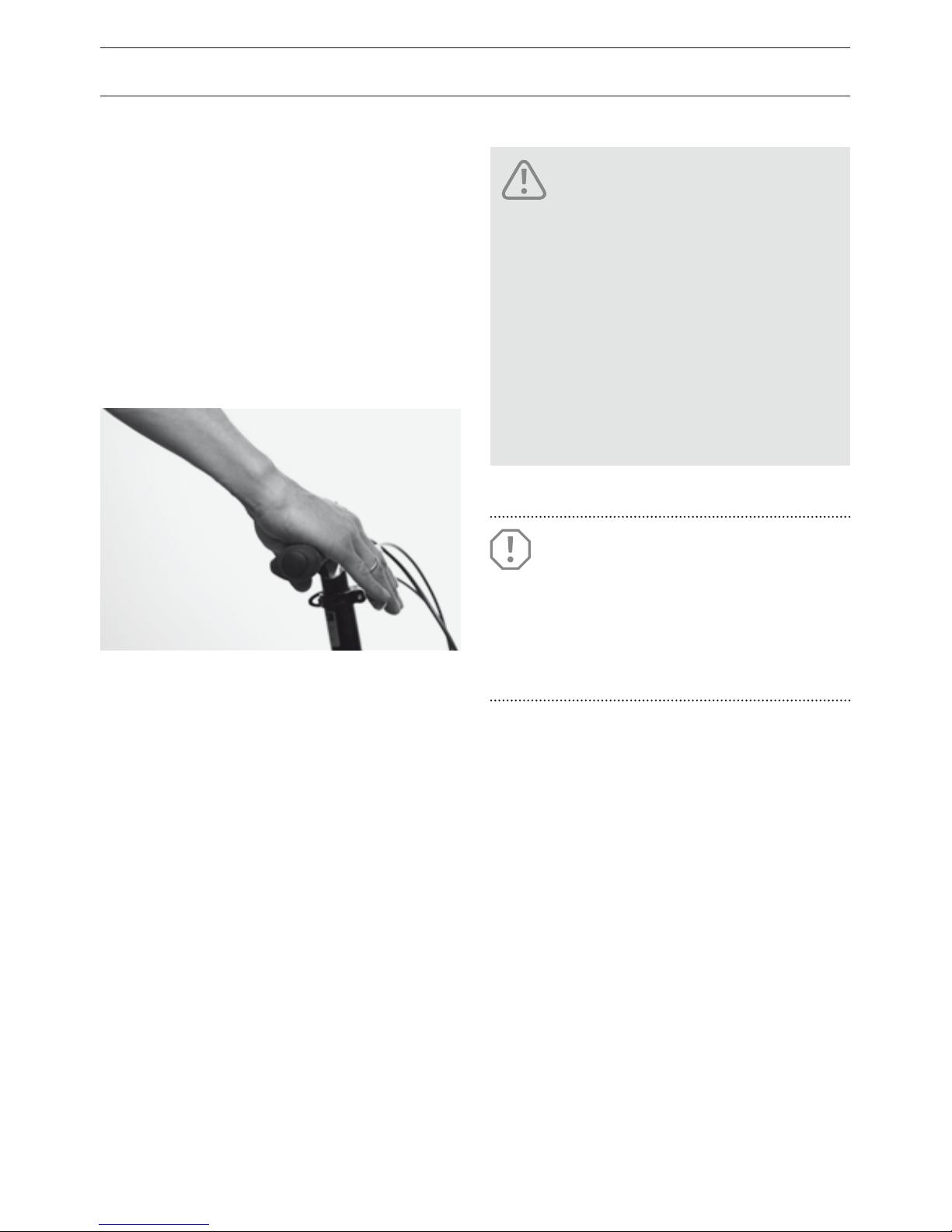
• There’s a small adjuster screw just near
where the cable goes into the lever hous-
ing (see arrow on diagram). Screw this
adjuster in, and observe how the lever
position changes.
• When you’ve reached the desired posi-
tion, you must check that there’s still
enough available motion so that there’s
a little lever movement before the
brakes “bite” (see page 31).
When you change saddles,
check that the saddle rails are
designed for a 7mm clamp. Other
types of saddle rails may cause
failure of the seat clamp and lead
to an accident.
You shouldn’t be able to pull the
levers all the way to the handlebar! Maximum braking power
should be reached before this!
DANGER!
DANGER!
Page 22
20
ADJUSTING THE RIDING POSITION, PEDALS
Once you’ve adjusted the handlebar angle,
you need to adjust the brake lever position.
Loosen the hex-key bolt on the lever hous-
ing clamps.
• Turn the lever on the handlebar. Sit on the
saddle and grip the levers with your fingers.
Check that your hand makes a straight line
with your forearm.
• Retighten the bolts (torque setting 5-6 Nm).
BAR ENDS
Bar ends oer additional hand positions.
They are generally fitted so that the hands
rest comfortably on them, when the rider is
in a slightly leaned forward position. They
are usually angled upwards at about 25
degrees.
PEDALS
Grease the threads before assembly and
insert the pedal by rotating the axle 2 or
3 turns by hand. The left/right pedal has a
“L”/“R”-sign. Tighten the pedals to 15 Nm.
Always be sure that securing
bolts on stem, handlebars, bar
ends and brakes are tightened to
the appropriate torque setting.
The appropriate values are listed
on pages 62. Otherwise, it’s possible that parts may come loose
or break. This can lead to serious
accidents.
DANGER!
ATTENTION!
The handlebar stem is designed for
handlebar bags or baskets up to 3
kg (max. load including the weight
of bar and basket).
Page 23
21
ADJUSTING THE SUSPENSION
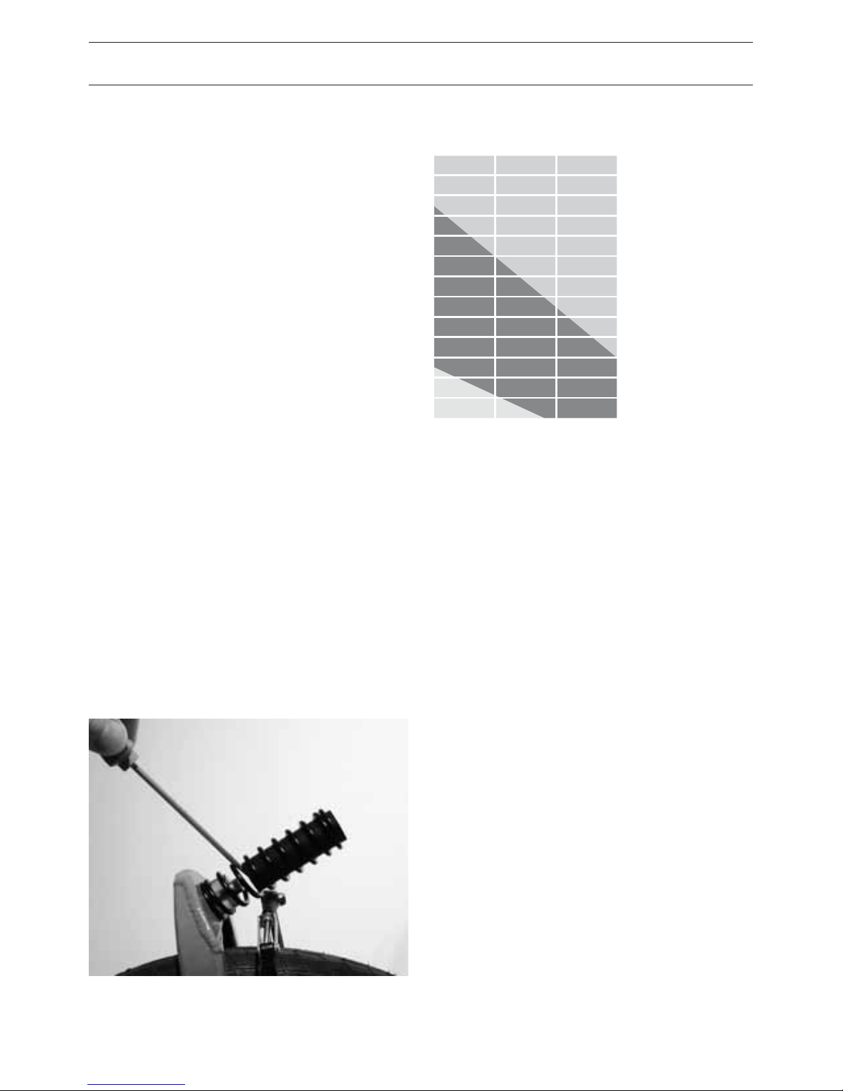
CHANGING THE REAR ELASTOMER
The Birdy is fitted as standard with a red
elastomer, which is suitable for a very wide
range of conditions. It can, however, some-
times make sense to fine-tune the riding
qualities to your personal taste by changing
the rear elastomer to reflect your particular
weight, riding style and the state of your
local roads. A softer yellow elastomer and a
harder, green one are available. To change it
simply fold the rear swingarm down and pull
the elastomer o with your hand. The fol-
lowing table may help you select the correct
elastomer. Please note that elastomers get
“harder” at low temperatures. It could there-
fore be a good idea to change to a “softer”
elastomer in winter.
CHANGING THE FRONT ELASTOMER
The front elastomer can also be exchanged
for a harder version. The standard version is
hollow, while the harder version is solid.
The elastomer can be pushed out of the
spring with a screwdriver.
yellow
red
Choice of rear elastomer kg
110
105
100
95
90
85
80
75
70
65
60
55
50
Comfort Allround Sport
green
Page 24
22
QUICK RELEASE
Quick releases hold wheels, seatpost and the
height-adjustable stem in position.
A quick release consists of two basic parts:
• A lever (1) on one side of the hub that pro-
duces the clamping force.
• A locking nut (2) which is threaded on the
opposite side that sets the tension.
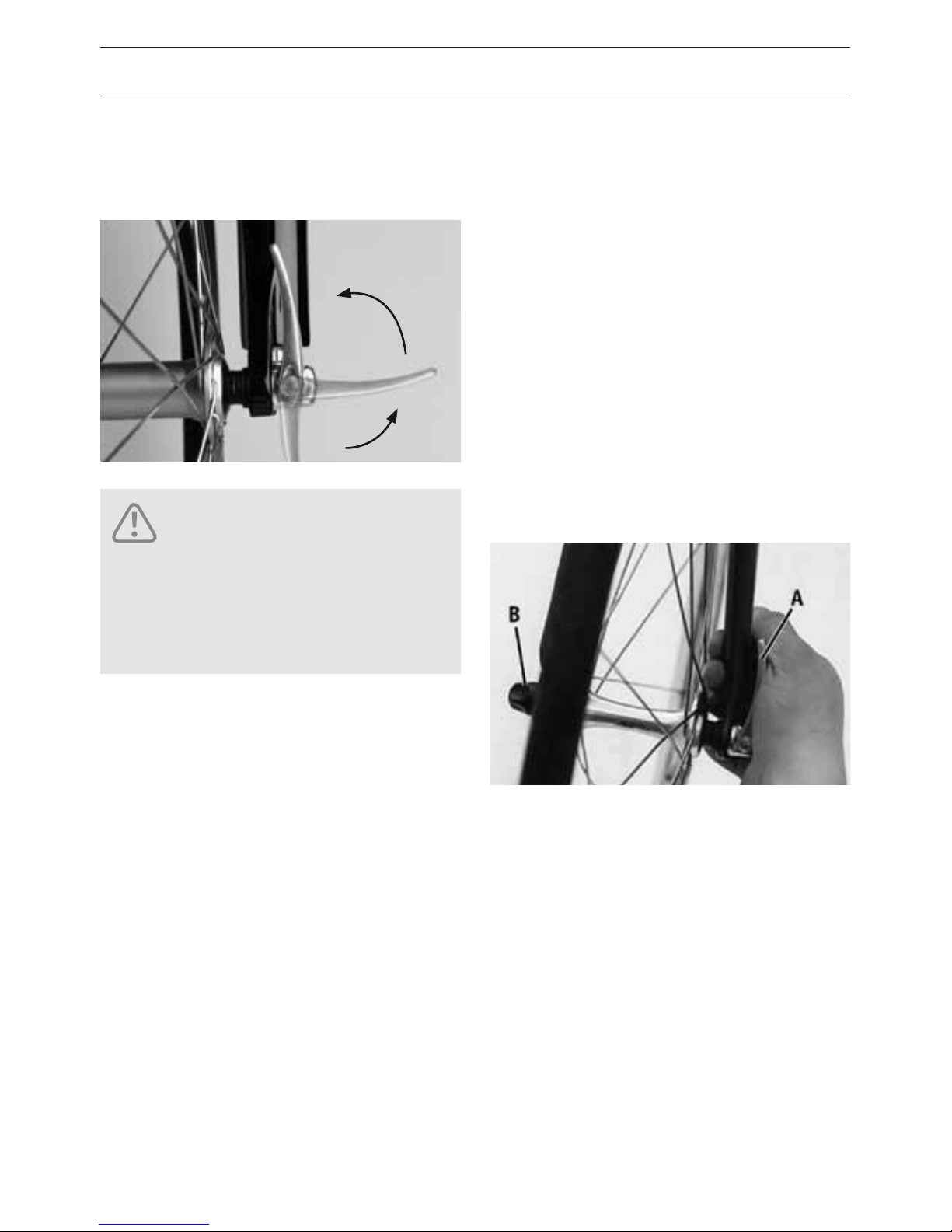
HANDLING OF QUICK RELEASES
Open the lever. You should now be able to
read the word “Open”.
• To close it, move the lever so that on the
outside it reads “Close”. At the beginning
of the closing movement, about half of the
lever travel, the lever must be slightly tight.
• During the second half of the lever’s travel,
the leverage increases significantly. Finally,
the lever is very tight and is dicult to
move. Use the palm of the hand to close
the lever. Once closed the lever must be
parallel to the wheel and not project out
laterally.
• Check the t by attempting to turn the
closed lever. When the lever rotates, it is
not safe to use the bike. You have to open
it again to retighten it. Do this by turning
the locking nut one-half turn (while holding
quick release).
An incompletely or improperly
closed quick-release can result
in parts coming loose or even a
crash resulting in serious injury!
DANGER!
Page 25
23
• Check the t again. When the lever no
longer rotates, it is clamped properly.
• Lift the wheel several inches o of the
ground and give the top of the tire a little
whack. A securely fixed wheel should
remain in the frame.
• To check the handlebar quick release,
wedge the front wheel between your legs
and attempt to twist the handlebar. If it
doesn’t turn when you do this test, the
stem is secure.
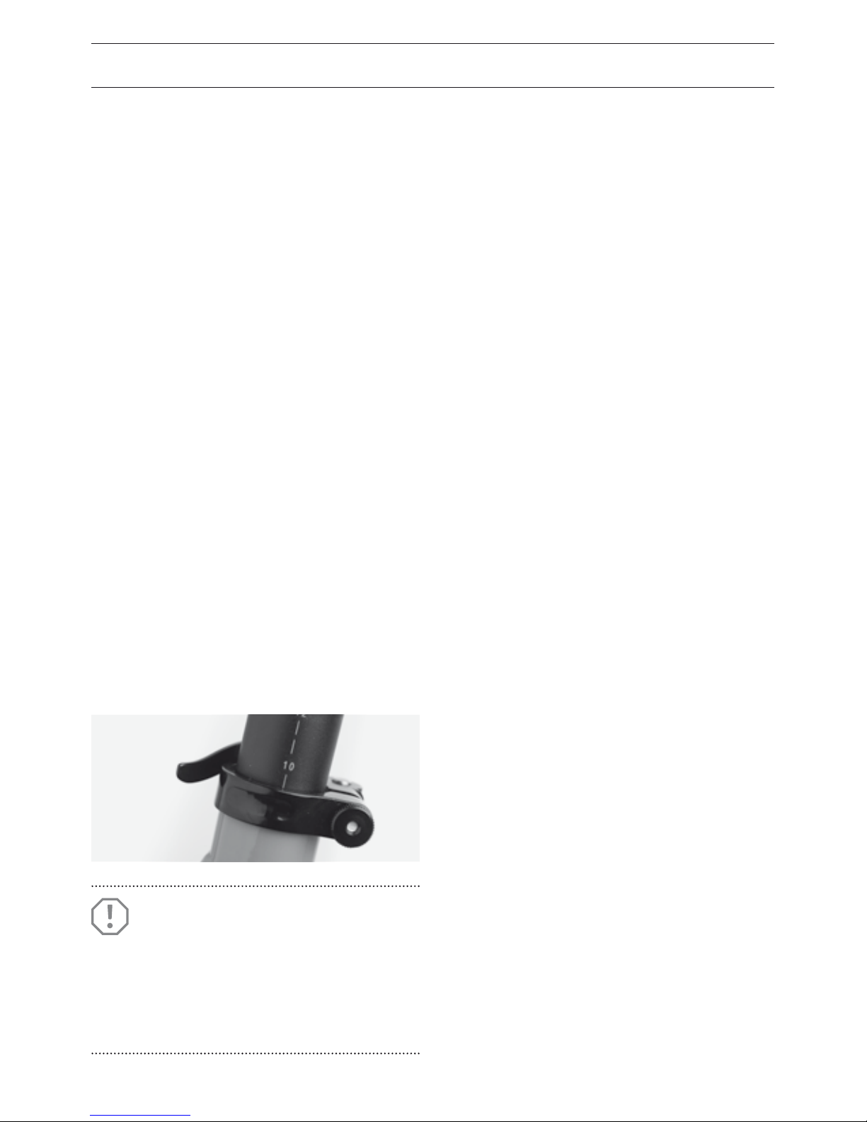
SEATPOST CLAMP
The quick release nut has to be adjusted that
on the one hand the seatpost is fixed tight
enough and on the other hand the seat-
post can slide easily after opening the quick
release.
The position of the clamp should be with the
lever at the right side. When used with the
expedition carrier the clamp must be rotated
about 90 degrees.
ATTENTION!
Check the position of the clamp
regularly. The clamp should sit
completely ush with the seat tube
to ensure best clamping function.
Page 26
24
STEM FOLDING HINGE
TENSION LEVER
This type of folding hinge type allows the
adjustment of tension and action point.
FUNCTION OF THE FOLDING HINGE
The folding hinge is correctly adjusted by
Riese & Müller at our factory. However it can
be maintained by an expert.
The following description helps to find and
eliminate errors.
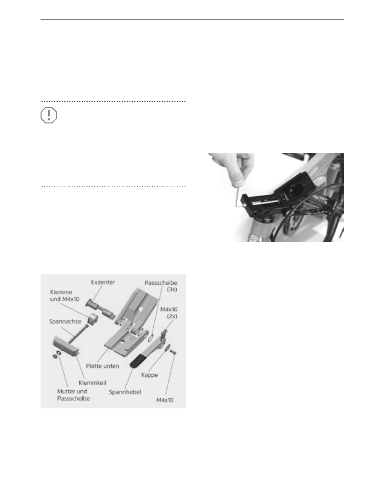
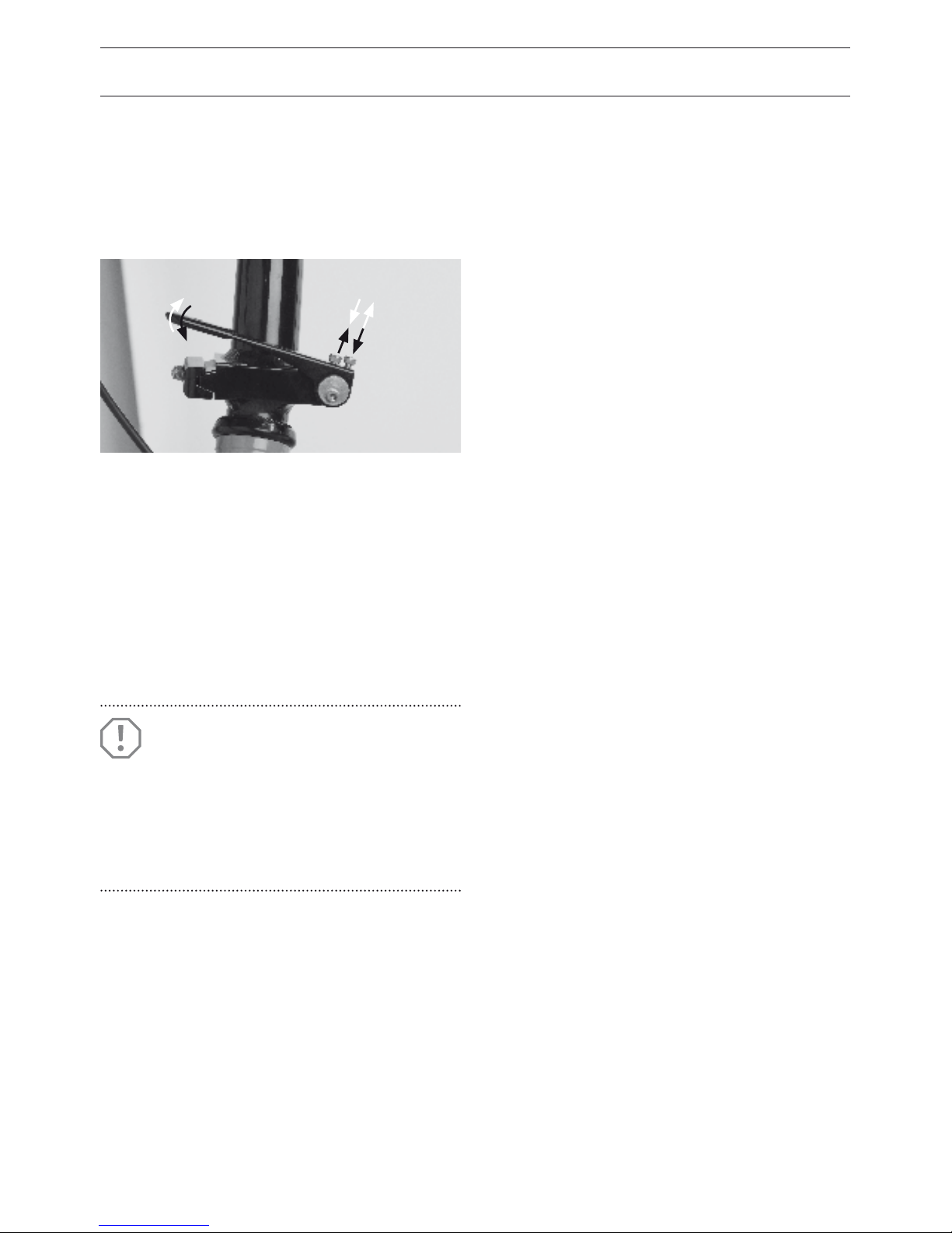
HOW TO ADJUST THE CLAMPING FORCE
The mechanism is adjusted by turning the
tension rod.
• Close the lever. Loosen the nut several
turns.
• Open the lever.
• Now you can adjust the tension rod with a
2.5 mm allen wrench.
• Close the lever again and tighten the nut
(torque setting 2-3Nm)
• Check the tightening force. The lever should
move easily but should have no play when
closed. If this is not, the tension rod has to
be adjusted again.
ATTENTION!
This folding hinge consists of
many parts and any maintenance
is best done by your dealer. Incorrect assembly can lead to malfunction and loss of steering control!
Page 27
25
HOW TO ADJUST THE AXIAL PLAY
If there is too much play first check if the
right bolt M 4x10 is suciently tightened.
• To reduce the play, rst loosen both bolts
M4x16. Slightly tighten the left bolt M4x10.
Watch for correct fit of the cap.
• Tighten both bolts M4x16 again (torque set-
ting 2-3 Nm).
• If the lever becomes sti, there is too little
play. Loosen both bolts M 4x16 and then
bol t M 4x10.
• Loosen the lever and tighten both bolts
M4x16 again (torque setting 2–3 Nm).
• Tighten left bolt M 4x10 (torque setting
1 Nm).
HOW TO ADJUST THE ACTION POINT
The point of maximum clamping force should
be reached shortly before the end position.
Otherwise it has to be adjusted.
• Open the left bolt M 4x10 for a half rotation.
• Loosen one of the M 4x16 bolts and tighten
the other one (see arrows in picture). The
white arrows show how to achieve an
earlier action point.
• After correct adjustment of the action point
please tighten both bolts M 4x16.
• Check again for correct tightening force.
ATTENTION!
Always tighten the left bolt M 4x10
after tightening both bolts M 4x16.
Otherwise the axial play can
change!
Page 28

26
STEM FOLDING HINGE
HOW TO GREASE THE FOLDING HINGE
In general there is no maintenance needed.
But after frequent use or after heavy rain we
recommend to clean the folding hinge and to
apply some viscous oil.
HOW TO DISMANTLE THE FOLDING HINGE
The folding hinge should be dismantled only
by an expert.
• Open the lever and remove left and right
bol t M 4x10.
• Loosen both bolts M 4x16.
• Push the eccentric to the right side until you
can see the grub screw at the right side.
Loosen the grub screw.
• Remove bolt from the eccentric.
• Clean all parts with a dry cloth.
HOW TO ASSEMBLE THE FOLDING HINGE
• Grease inside of shell and the areas of
eccentric and bolt which touch the folding
hinge. Grease the cone and the washers.
• Place the washers on the folding hinge
plates (use some grease to hold them on).
• Place the cone and the tension rod
together with the shell into the folding
hinge plate.
• Push the eccentric through washer, folding
hinge plate and shell.
• Push the bolt onto the eccentric and as-
sembly the right bolt M 4x10. Tighten the
grub screw. Take care that the grub screw
hits the flat section of the eccentric.
• Put the lever onto the eccentric. As-
semble cap and left bolt M 4x10. Do not
tighten the bolts.
• Adjust clamping force, action point and
axial play. Take care of correct tightening of
all bolts.
ATTENTION!
Now the stem is loose and can
fall down! Watch out for the thin
washers.
Page 29
27
REAR SWINGARM CATCH
When unfolded, the rear swingarm is at-
tached to the frame with a black plastic catch.
You should adjust the position of this catch
so that it engages automatically when you
unfold the Birdy, and so that there’s no play.
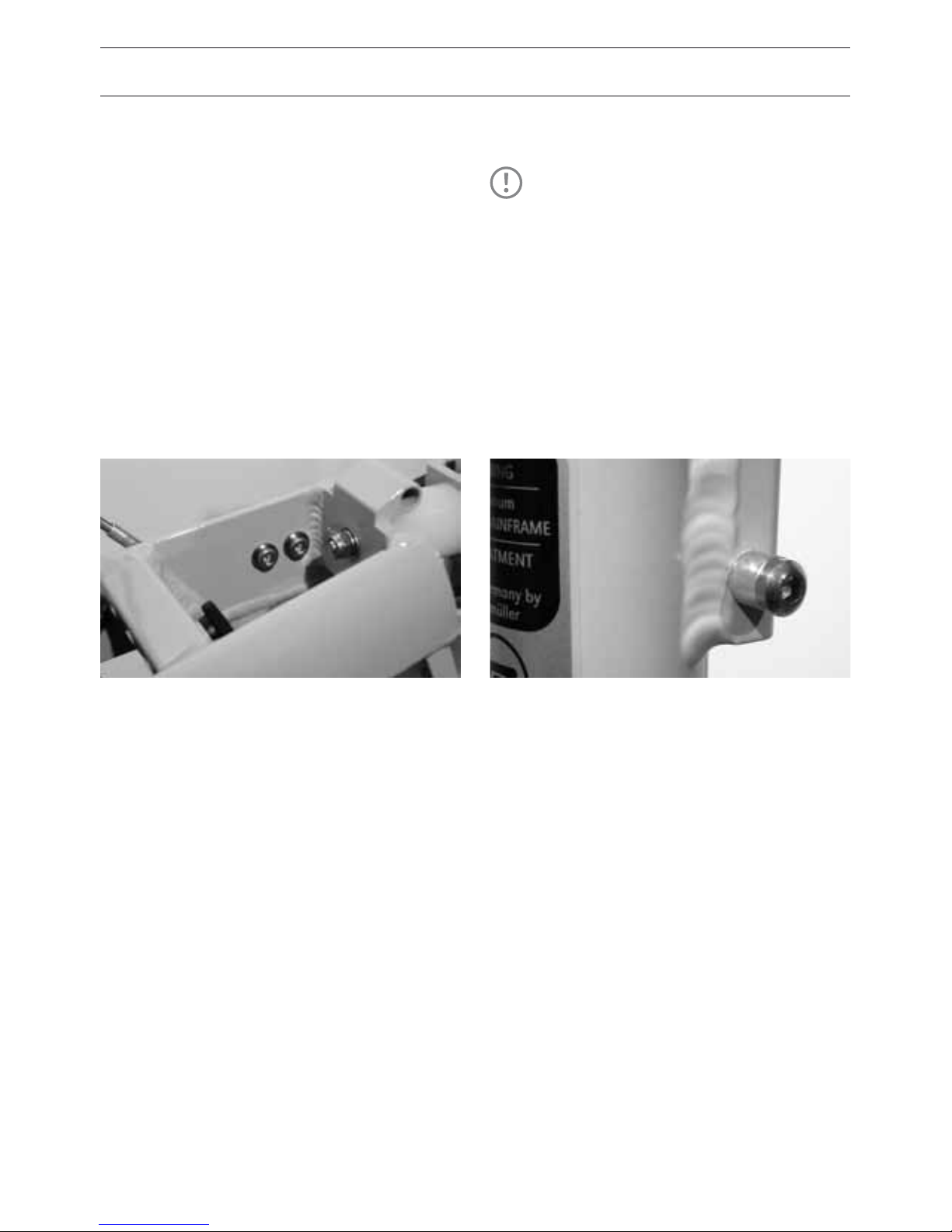
HOW TO ADJUST THE REAR CATCH
• To adjust it, you must loosen both allen
bolts inside the rear swingarm box profile.
• The catch can then be pushed inwards or
outwards.
• Finally, retighten both bolts with a torque
of 2-3 Nm.
• Open and close the catch several times to
check the adjustment.
• The M 6 x 12 bolt is secured into the main
frame with threadlock adhesive. The bolt
should be screwed in just far enough that
when the catch is engaged, it’s under slight
tension inwards.
• If the tension is no longer sucient for the
catch to engage, you need to pretension
the catch: fold the rear swingarm slightly
forwards, remove the elastomer and bend
the plastic catch firmly inwards for a few
seconds.
TIP!
Lean on the saddle during
adjustment to reduce play!
Page 30
28
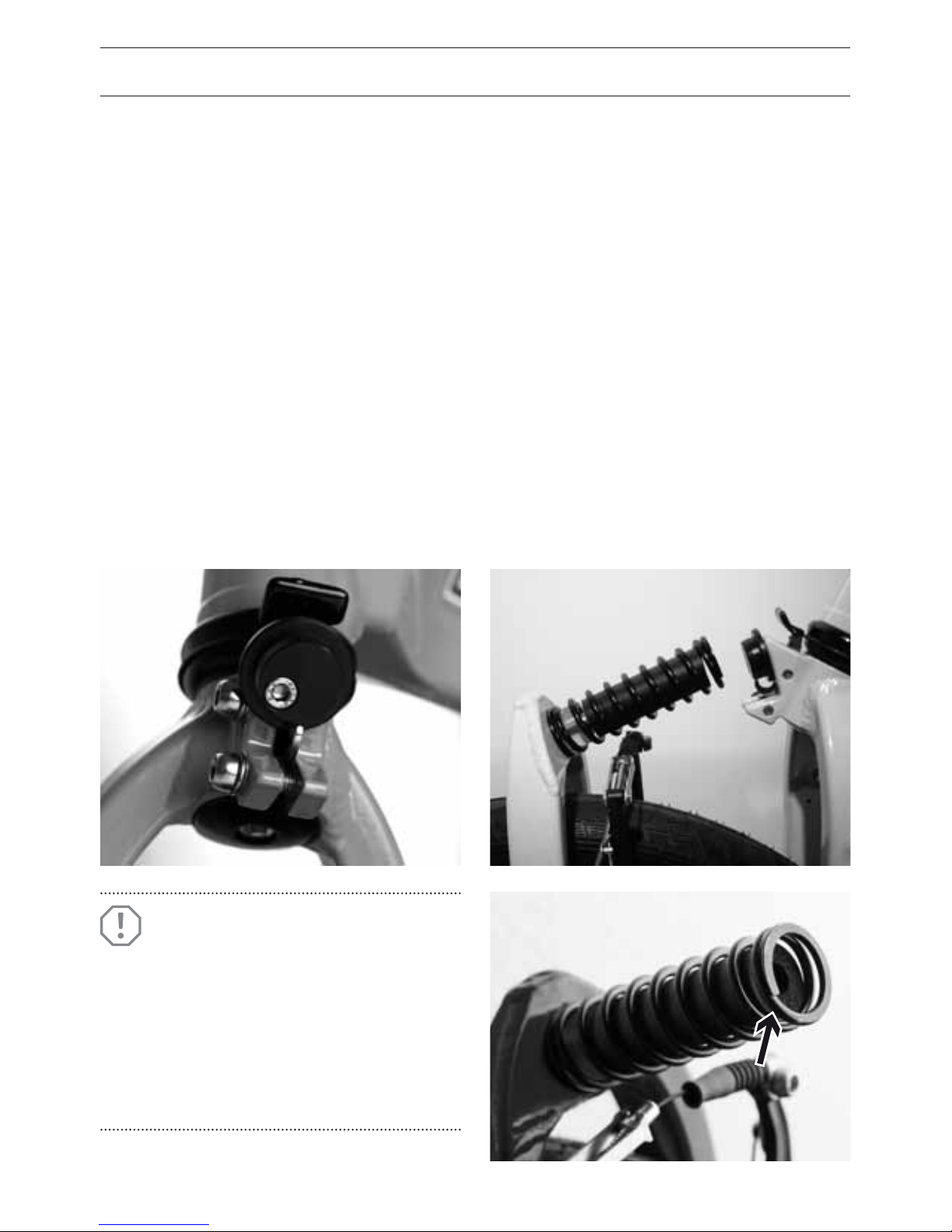
FRONT SWINGARM CATCH
When you unfold the Birdy the front suspen-
sion spring engages in the front swingarm
catch. This catch consists of a metal hook,
which pivots on a shaft mounted on the fork
crown, and it’s kept in tension with a small
spring. If this hook doesn’t move or if it is not
being pulled back properly by the spring, the
two fork clamping bolts may be too tight,
or the spring may have failed. In this case,
please ask your dealer to help. The hook
should engage in the last turn of the spring
and should fix it in position. To fold, press
down on the suspension catch: this moves
the hook clear of the spring.
HOW TO ADJUST THE FRONT
SWINGARM CATCH
• If the catch hook doesn’t engage cleanly in
the first turn of the spring, the spring must
be rotated.
• Loosen the fastener at the bottom of the
spring with a long 5mm hex key, which
you should insert from the free end of the
spring. Only turn the spring far enough to
ensure that the top turn of the spring ends
in the seven-o-clock position, and engages
the catch hook without play. The spring
must be carefully lined up with the black
plastic cap so that it slides easily onto the
cap and engages with the catch.
ATTENTION!
Do not ride if the front swingarm
catch is not engaged correctly. The
result could be a sudden unwanted
folding of the front swingarm
which could lead to a serious
accident!
Page 31
29
• Finally reattach the spring in place with a
torque of 6 – 8 Nm.
If the fork spring doesn’t engage without
play, both the spring position and that of
the black plastic cap can be adjusted. Exact
adjustment can require some experience,
and any problems should be referred to your
Birdy dealer.
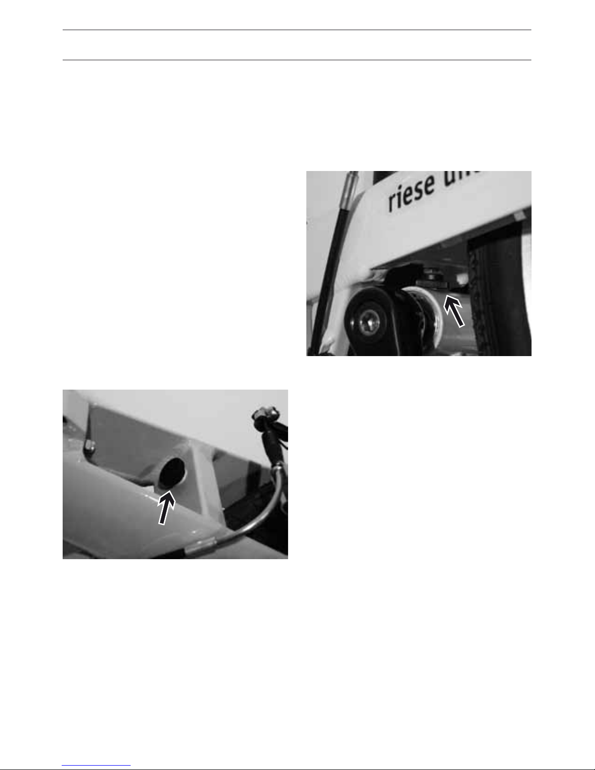
HOW TO ADJUST THE STOPBOLTS
The new Birdy with monocoque frame has
two bolts with plastic head to adjust the
swingarms end position at folding. The front
bolt always has to be tightened completely.
The thread has to be secured with a small
drop of Loctite.
The bolt at the bottom has an additional
lock nut. Adjust the bolt to achieve minimal
play in the rear swingarm after pushing
down on the seatpost.
Page 32

30
BRAKES
HOW TO USE THE BRAKES CORRECTLY
The Birdy is equipped with particularly pow-
erful brakes. The stopping distance however
depends also on the rider’s skill. No worries
as this can be trained.
When you brake, your weight is shifted to
the front wheel from the rear wheel. The
strength of the deceleration is the primary
factor in bicycle rollover with the secondary
factor being the traction of the tires. This
can be particularly problematic when riding
downhill. During an emergency stop try to
shift your weight as far back as possible.
Press both brake levers at the same time
and note that the front brake transmits
much more braking force due to the shifting
weight. Avoid, however, locking the front
wheel as this can cause slipping or even a
rollover.
If your bike is equipped with a coaster brake
and only one hand brake, the brake lever will
be located on the right side and will operate
the front brake. If your bike is equipped with
two brake levers, the one on the right oper-
ates the rear brake and the one on the left
operates the front brake.
Familiarize yourself with the orientation
or ask your dealer to change them to your
liking.
Make sure to familiarize yourself with the brakes gradually.
Practice emergency braking in
a trac-free area until you are
able to safely control the bike.
This can prevent accidents while
on the road.
After long downhill sections
the rims can become very hot.
Rest regularly to let the rims
cool down. Overheated rims can
lead to a puncture or even an
accident!
Some dealers change the orientation of the brake levers because
there are different opinions as
to which orientation is correct.
Therefore please check before
your rst ride, whether the above
orientation matches your bike
and your preferences.
DANGER!
DANGER!
DANGER!
Page 33
31
HOW THEY WORK, AND HOW THEY
GET WORN OUT
By using a brake lever or reverse pedaling a
fixed pad is pressed onto a rotating brak-
ing surface and causes friction. This friction
causes the rotating wheel to slow. In addi-
tion to the force with which the pad presses
against the surface, the so called friction
coecient between the fixed pad and the
braking surface is crucial. If water, dirt or oil
gets onto the braking surface, the friction
coecient is worsened. This is the reason
why a rim or disc brake does not respond as
well in the rain.
WEARING
The friction between the brake pads and the
rim leads to the wearing of both the pad and
the rim! Riding often in the rain increases the
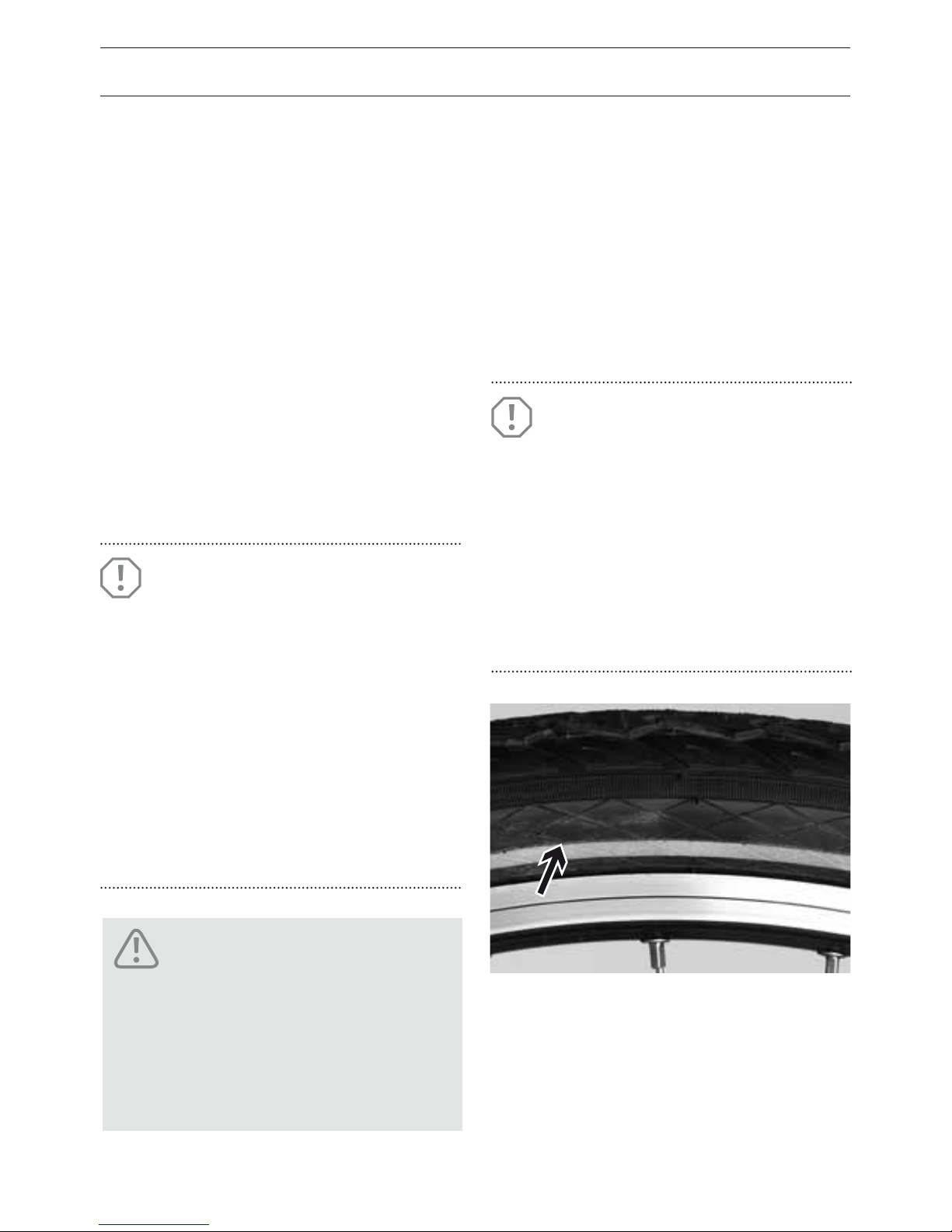
wear. If the rim sidewall is abraded to a criti-
cal level, the tire pressure will cause the rim
to burst. The wheel can jam or the tube may
burst, both of which can lead to an accident.
ATTENTION!
ATTENTION!
By the time you have worn
through your second set of brake
pads, it is time to have your
dealer check the thickness of your
rims’ sidewalls. For rims with a
wear indicator, the rim must be
replaced when the indicator is no
longer visible.
Moisture decreases the braking
effectiveness. When riding in rainy
conditions expect longer braking
distances! When replacing brake
pads, you should only use pads
that have been specied for your
system. Your dealer can advise you
in the matter. The braking surface
of rims should be absolutely wax,
grease and oil free.
Damaged brake cables in which
individual wires protrude must
be replaced immediately. Brake
failure and an accident can result. Ask your dealer for advice.
DANGER!
Page 34
32
BRAKES
CHECKING, ADJUSTING AND BALANCING
VBRAKES
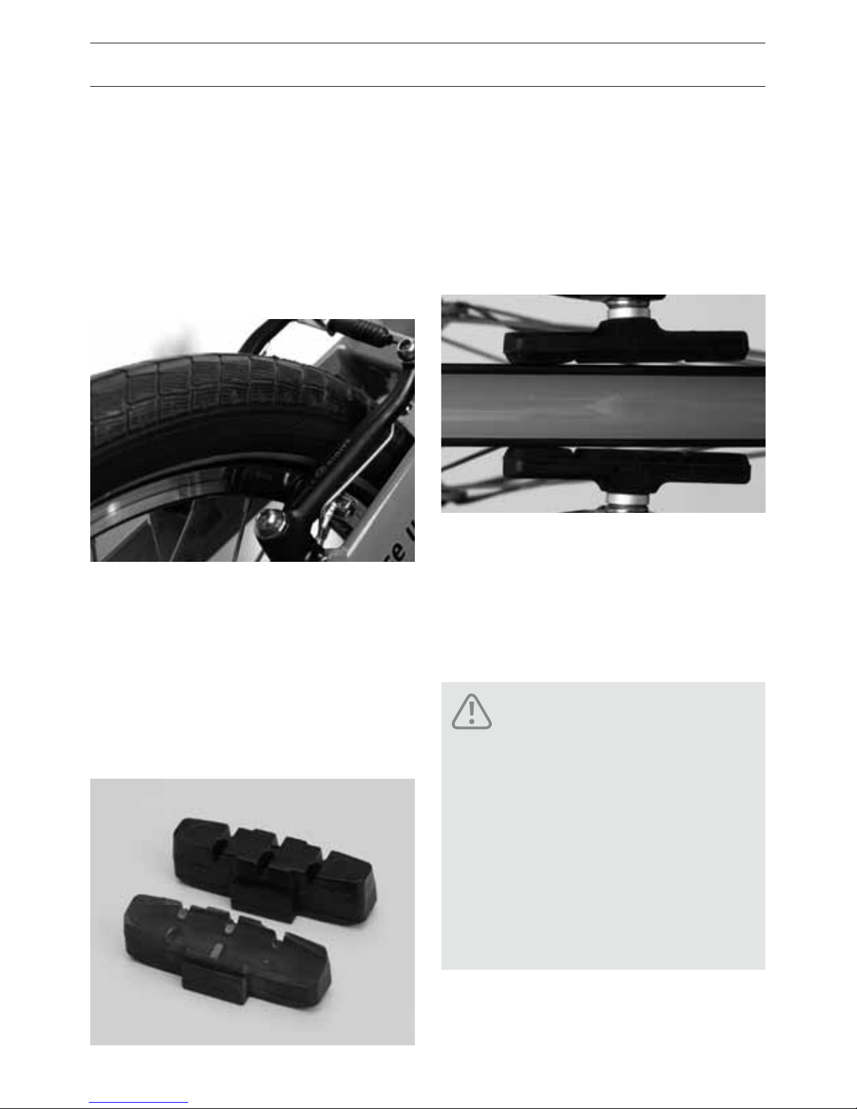
V-brakes consist of separately mounted
brake arms on the left and right side of the
wheel. When the brake arms are pulled to-
gether with a cable the pads rub on the rim
generating friction.
Function check:
• Check that the brake pads are properly
aligned with the rim and that they have
sucient thickness. This can be seen by
checking the transverse grooves in the
brake pad. When these grooves are worn
down, it’s time to change them.
• Additionally the front portion of the brake
pads should be the first to touch the rim.
Once touching the rear portion of the pad
should be one millimeter away from the
rim. This v-shaped orientation helps pre-
vent the squealing of the brake pads.
• Both pads must simultaneously hit the rim
when the lever is pulled
• The brake lever must exhibit a reserve in its
travel. It should not pull up to the handle-
bars even during emergency braking.
Make sure that the pads touch
the sidewall with their entire
surface. Otherwise brake failure
or wheel lock could lead to an
accident. Also make sure that
the surfaces of the brake do not
touch the tires. Incorrectly set
brake pads can cause tire rubthrough leading to a tire failure.
DANGER!
Page 35
33
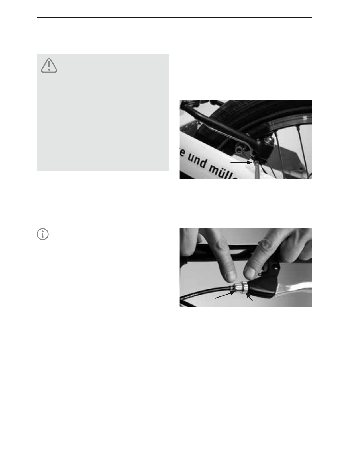
Adjusting:
The V-brakes have to be synchronized by
adjusting the spring preload using the
respective adjustment screws (A).
• When the brake lever pulls all the way to
the handlebar, the brake cable must be
readjusted.
• Loosen the knurled lock ring (B) where the
brake cable enters the brake lever.
• Turn slotted barrel adjuster (C) a few
turns. The free travel of the brake lever is
reduced.
• Hold the barrel adjuster (C) while tightening
the lock ring (B) firmly against it so that the
barrel adjuster is locked in place.
• Check that the slot in the screw does not
face upwards or forwards, as this can allow
water and dirt to get in.
A
B
C
Adjusting brake blocks against
the rim requires a good degree
of mechanical skill. Errors could
lead to brake failure and accidents. If in any doubt, leave the
adjustment of brakes or changing brake blocks to your dealer.
Poorly adjusted brakes can lead
to serious accidents!
DANGER!
TIP!
Be sure to try the brakes in a
trac free area to get a feel for
the newly adjusted brakes!
Page 36
34
BRAKES
REAR COASTER BRAKE
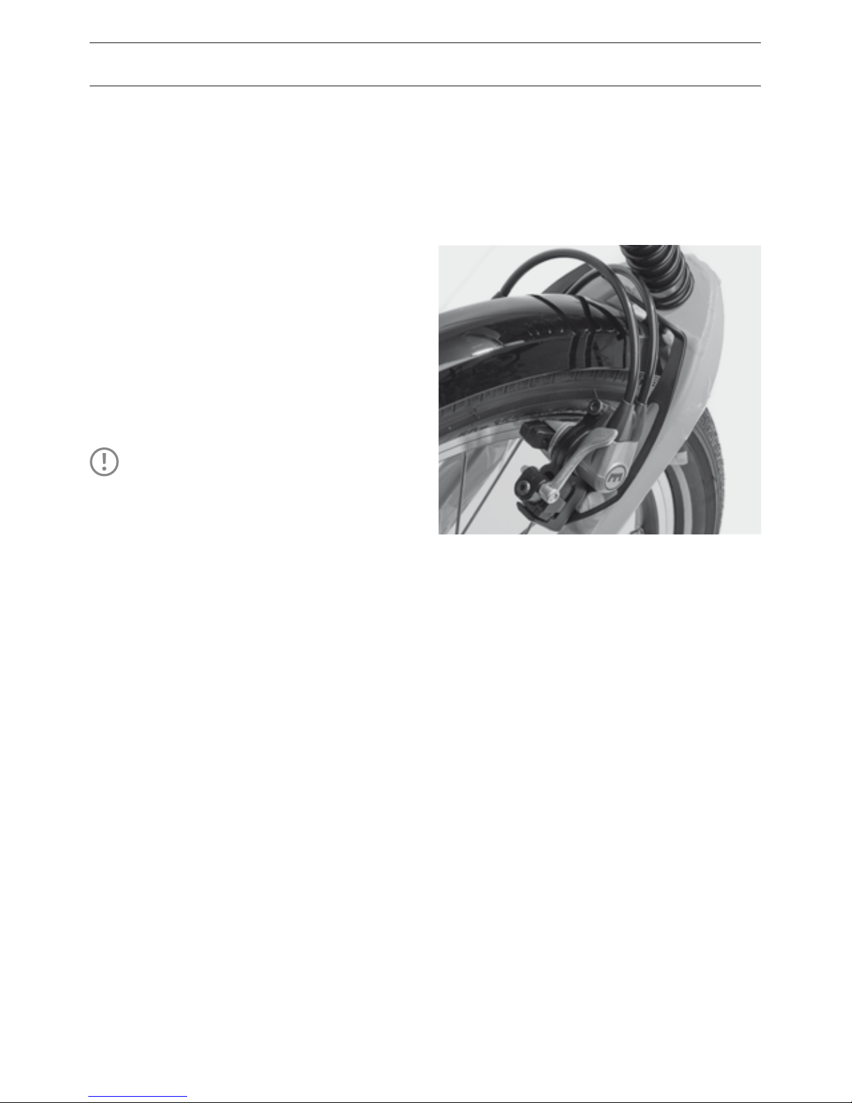
The Birdy city is equipped with a coaster
brake. Coaster brakes allow you to apply
the brake to the rear wheel at any time by
pedaling backwards. Riese & Müller only use
coaster brakes whose braking performance
is not influenced by the current gear that one
is using.
• Check regularly the tight t of the bolts
which are fixing brake reaction arm of the
coaster brake.
HYDRAULIC RIM BRAKES
For information regarding hydraulic rim
brakes please refer to the separate enclosed
instructions from Magura.
TIP!
The Birdy city is equipped with a
chain tensioner and so you have to
pedal back a little until the brake
becomes active.
Page 37
35
Transporting the bike
The hydraulic brake system is completely
sealed so the bike can be transported lying
or upside down without brake fluid leaking
out or air intruding.
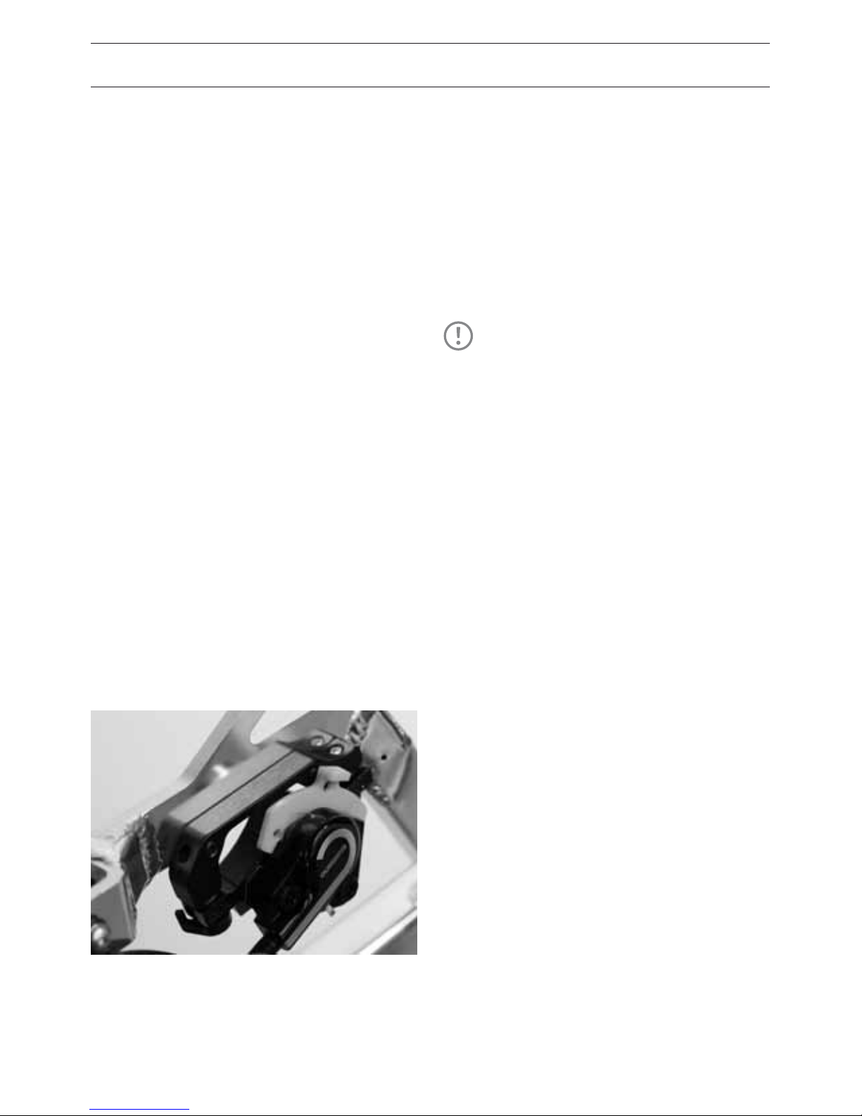
Mechanical Disc Brakes
To adjust the break pods use the special
screw which is located near the stem. For
more information about settings, please re-
fer to the instructions supplied by the brake
manufacturer.
DISC BRAKES
The Birdy Disc models use a powerful disc
brake system that supplies enormous brak-
ing power while being easy to modulate.
Wear
These brakes compensate pad-wear auto-
matically making it unnecessary to readjust
your brake pads. As such you won’t be able
to recognize pad wear by a changing brake
lever feel.
Please make sure, that the thickness of
your brake pads is checked regularly by your
authorized dealer.
Disassembling the wheels
After the wheel is removed you should no
longer operate the brake lever. The brake
pads will press together making it dicult to
mount the wheel. After removing the wheel,
insert the transportation safety shims to
ensure a sucient distance between the
brake pads.
TIP!
It is useful to carry spare brake
pads with you on longer tours!
Page 38
36
SHIFTING SYSTEM
THEORETICAL FOUNDATION
The shifting system on the bike is used to
adapt one’s own performance to the terrain
and the desired speed. The physical work is
not reduced by the shifting system rather
the force required per crank revolution is
changed.
PROPER SHIFTING
Gradients can be powered up using low
gears and moderate force but you’ll have
to pedal faster. Downhill you can travel a
greater distance per turn of the crank. The
speed will be correspondingly high. Like
a car you must maintain your optimum
“engine” speed to perform well. What’s key
to your performance is keeping the number
of crank revolutions per minute (cadence)
above 60. Racing cyclists typically ride with
a cadence of 90 – 110. This rate naturally falls
o a bit during hill climbs but you should still
maintain smooth pedaling. The incremental
shifting steps and ease of use of modern
shifting systems oer the best conditions for
an ecient ride that is easy on your knees.
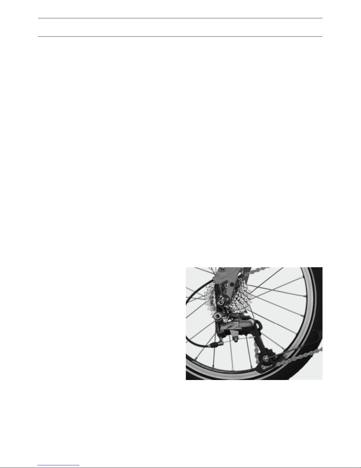
DERAILLEUR SYSTEM
The derailleur on the bike is currently the
most eective systems in terms of power
transfer. In a clean and well-oiled system
about 97 – 98 percent of the energy placed in
the pedals is transferred to the rear wheel.
Despite this near optimal performance, many
cyclists fear a bike without a coaster brake.
This fear is unfounded. The operation of the
derailleur system leaves nothing to be de-
sired. With specially designed sprocket teeth,
flexible chains and precisely spaced shifting
steps, the system shifts very easily. Re-
member to engage the shifter smoothly and
momentarily stop applying pressure to the
pedals until the chain is on the next sprocket.
Even though the special tooth forms of
today’s sprockets allows shifting under load,
it shortens the life of the chain and therefore
should be avoided.
Page 39

37
SHIFTERS
Two dierent kinds of shifters are used
at the Birdy.
Twist grip
Rotating the right grip towards the driver
leads to an easier gear and rotating the
left grip away from the driver leads to an
easier gear. The grip indicates which gear
you are currently using. The shifter transmits
the commands to the transmission via the
Bowden cable.
Rapid Fire shifter
The thumb on the left side shifts to harder
gears and on the right side, easier gears. The
index finger on each sides shifts in the other
direction.
Practice shifting in a trac-free
area so that you can become
familiar with the rotation of the
shifters and pressing the levers.
The practice area should be free
of potential hazards.
DANGER!
Page 40
38
SHIFTING SYSTEM
CHECKING AND ADJUSTING SHIFTING SYSTEM
Your derailleur system was carefully set by
your dealer before handing it over to you.
During the first few kilometers the shift-
ing cables may lengthen thereby leading
to imprecise shifting. The chain then only
reluctantly moves to the next sprocket or
chainring.
Tensioning the rear derailleur
• Tension the cable using one of the screws
through which the cable passes (barrel
adjuster).
• After each tensioning check to see wheth-
er the chain moves easily to the next
larger sprocket. To check this you must turn
the cranks by hand or ride the bike.
• If the chain moves easily to the next larger
sprocket, then you must also make sure
that it also changes easily to the next
smaller sprocket. For precise setting,
several attempts may be necessary.
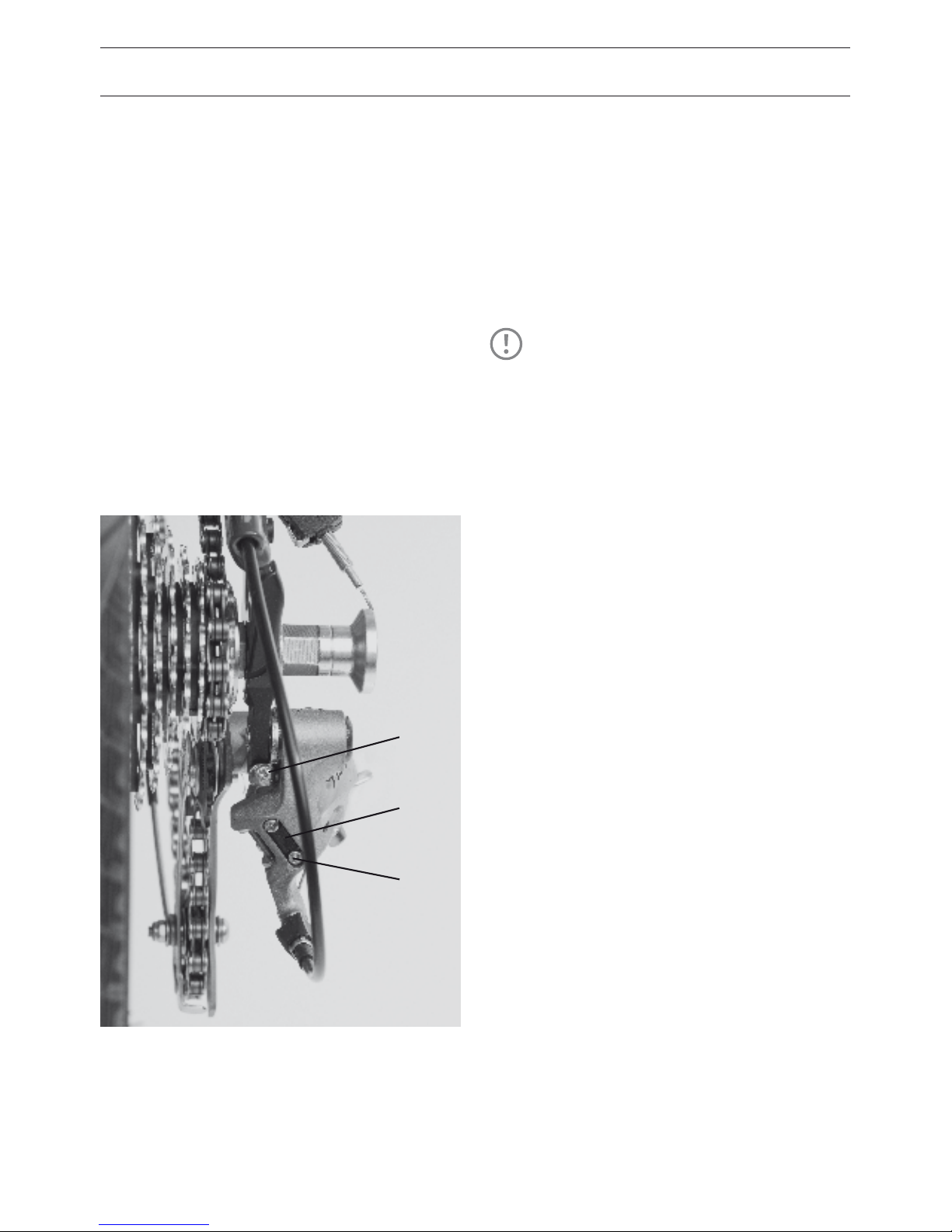
Setting limit screws on the derailleur
Limit screws restrict the swing area of the
derailleur to prevent the chain from drop-
ping o the small sprocket or from jumping
into the spokes. These screws are adjusted
by your dealer and are not adjusted during
normal use. If the bike has fallen over, check
to see if the derailleur or the hanger is bent.
Check the swing area. This also applies if you
install other rear wheels.
• Shift the chain to the right. Shift the lever to
the smallest sprocket.
• Look from behind to see whether the idler
wheel of the derailleur is located exactly
over the smallest sprocket. If the idler pul-
ley is too far out, you’ll have to adjust the
corresponding limit screw.
• The limit screws are often marked „H“
as the stopping point for the smallest
sprocket and „L“ for the stopping point for
the largest sprocket.
• Shift to the largest rear sprocket. Be careful
that the derailleur doesn’t shift immediately
into the spokes. With the chain on the larg
A
H
L
TIP!
If you cannot properly adjust your
shifting system, it could be due to
worn or kinked shifting cables. See
your local dealer for replacements.
Page 41
39
est sprocket, cautiously move the derail-
leur with your hand in the direction of the
spokes while rotating the rear wheel.
• If the idler pulley touches the spokes or the
chain begins to climb over the sprocket,
you should limit the pivot area. Turn the “L”
marked screw until the derailleur reliably
stops at the appropriate point.
• Now look at the position of the derailleur
cage relative to the cassette. There should
be space between the upper idler pulley
and the largest sprocket.
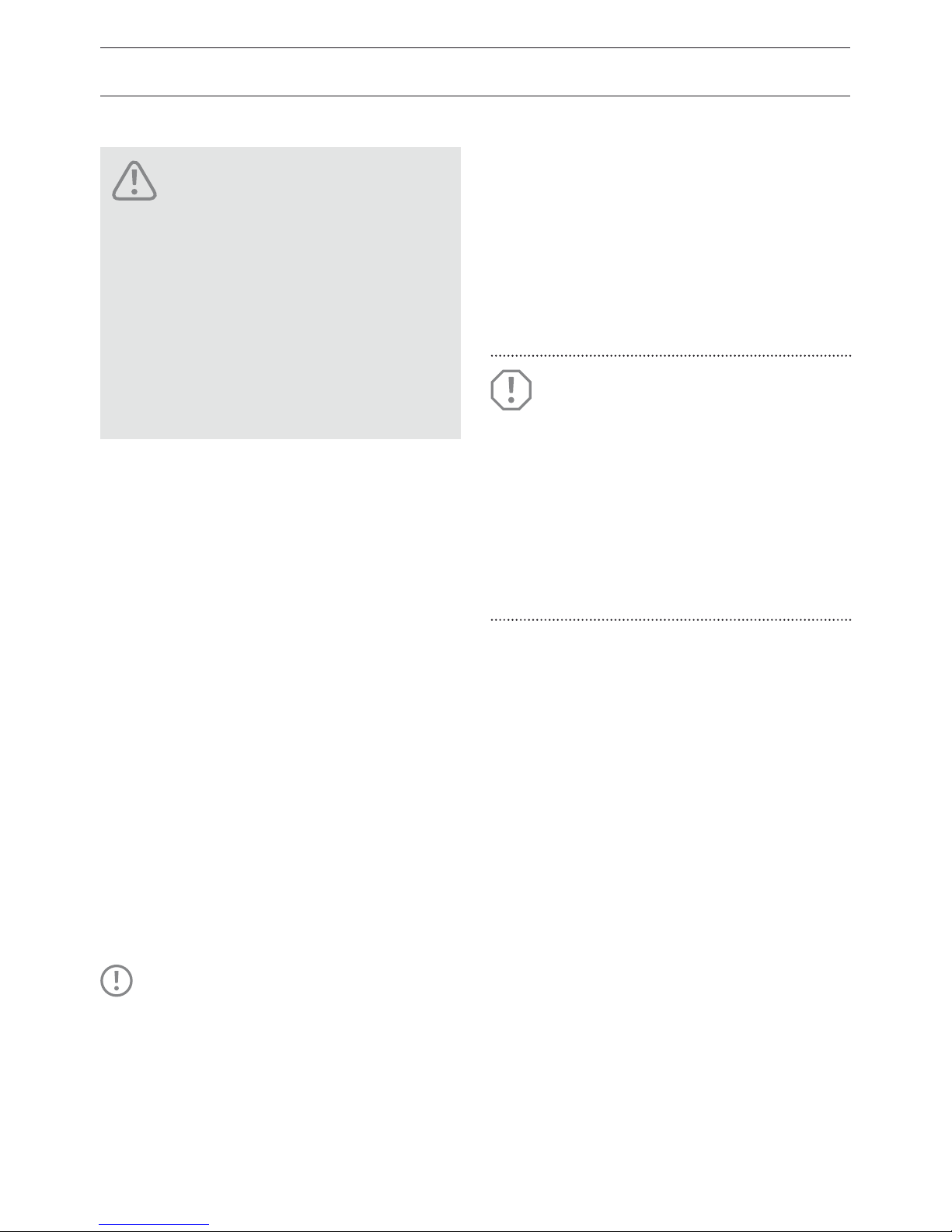
• The derailleur has a screw (A) to adjust this
distance on the front side of the dropout
• For the Birdy, screw this out as far as it will
go. The derailleur must be in its forward
most position.
THE CHAIN TENSIONER
The chain tensioner keeps the chain under
tension during the whole folding process.
The chain tensioner is mounted on the lower
derailleur jockey wheel, replacing its bolt
with a longer one. The bolt is secured on the
other side with a nut.
The adjustment of the front
derailleur is very sensitive.
Incorrect adjustment can cause
the chain to come off possibly
resulting in an accident. The adjustment of the front derailleur
is a matter for the professional
in the workshop.
DANGER!
TIP!
If you replace the rear derailleur,
check that the new one has the same
cage length as the old one. Otherwise problems can arise during folding,
as it can’t be guaranteed that the
chain will remain under tension.
ATTENTION!
The adjustment of the rear derail-
leur is dicult and should be left
to an experienced mechanic. Incorrect settings can cause serious
mechanical damage. If you have
problems with the system, please
contact your dealer.
Page 42
40
SHIFTING SYSTEM
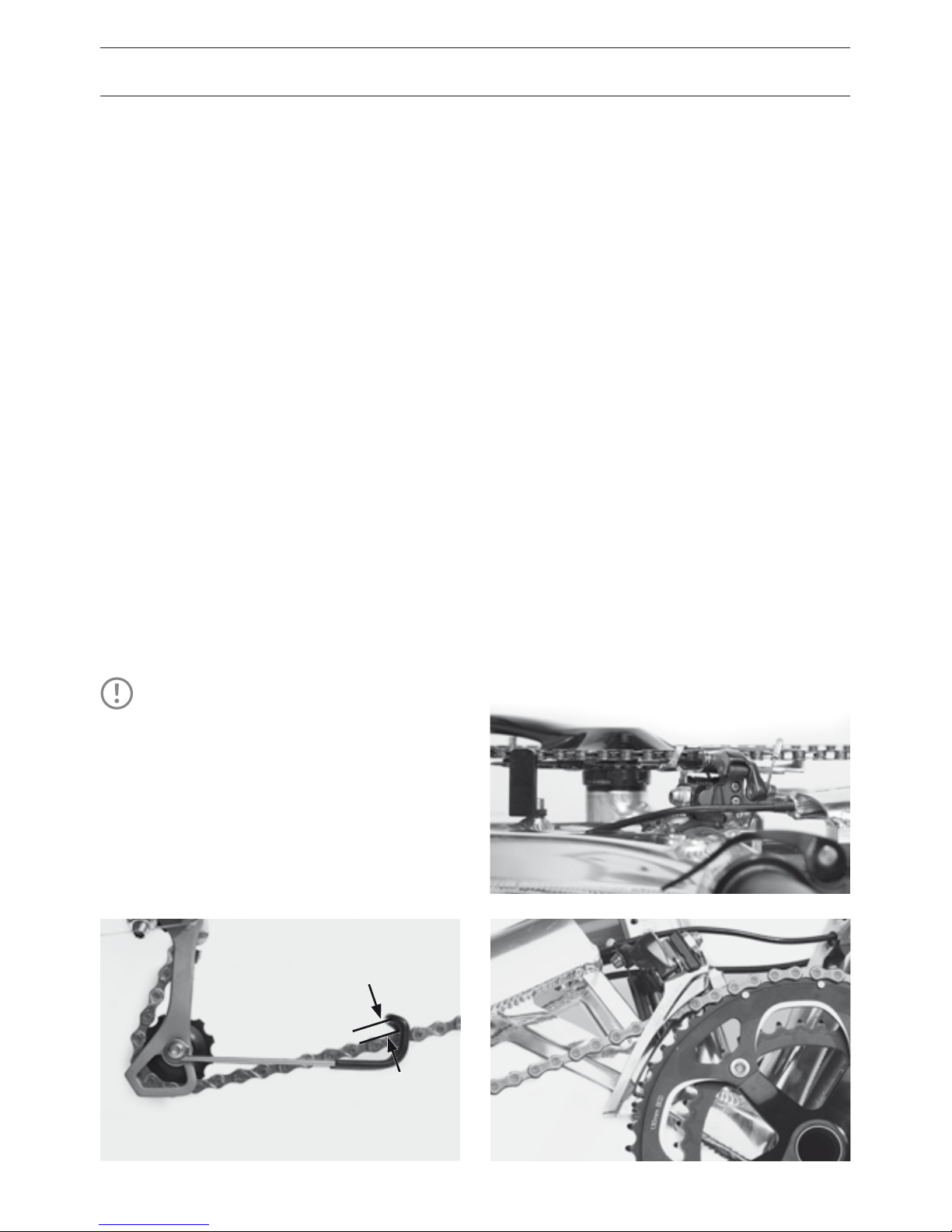
ADJUSTING THE FRONT DERAILLEUR
The adjustment of the front derailleur
requires a lot of experience. The setting in
which the chain does not rub the front de-
railleur is extremely small, the cable operat-
ing the front derailleur can stretch leading to
impaired shifting.
• Tighten the cable using the adjusting screw
just as you would on the rear derailleur
• For optimal performance, align the front de-
railleur exactly parallel to the chainrings with
between 1 and 3 mm of clearance between
the derailleur and the largest chainring
• To adjust the starting position of the front
derailleur, loosen the Allen screw on the
front side 2 to 4 times.
• The cable stops of the front derailleur are set
up as described in the section rear derailleur
adjustment.
How to adjust the chain tensioner
• Shift to the smallest sprocket
• The distance between chain and tensioner
should be 1 – 2 mm.
• To adjust the chain tensioner, rst loosen
the nut at the lower derailleur jockey
wheel. Then loosen the bolt.
• Adjust the chain tensioner.
• It is important that rst the bolt is tight,
then the nut is screwed tightly against it.
• Shift to the biggest sprocket. The chain ten-
sioner must not touch the tire or the rim.
The Birdy city chain tensioner
The chain tensioner Shimano Alfine with
additional chain tensioner is used for this
model. Adjustment is as describe above.
TIP!
Adjust a bigger distance between
chain and tensioner if your Birdy
is equipped with Big Apple tires.
This prevents touching between
tensioner and tires while shifting
into the smallest gear.
Page 43

41
HUB GEARS
One advantage of an internally geared hub
(IGH) is the encapsulated construction. The
technical mechanisms are almost completely
enclosed inside the hub. This prevents con-
tamination from dirt and grime. The chain
on an IGH system lasts longer than on an
equivalent derailleur system. A disadvantage
is the slightly higher power losses within the
hub. IGH are sometimes used in combination
with a derailleur, freewheel and rim, roller, or
integrated coaster brake.
How they work and how to use them.
It uses a twist grip shifter to select the de-
sired gears. The Shimano IGH can be shifted
under load while the Rohlo system requires
a momentary pause in the application of
pedal power. There are several methods
used to select gears for IGH and each hub is
dierent. For questions, see the instruction
manual of the manufacturer or your dealer.
Practice shifting in a trac free
area. Practice also using the
brakes. In road trac you may
be distracted from shifting and
braking by potential hazards.
DANGER!
Page 44
42
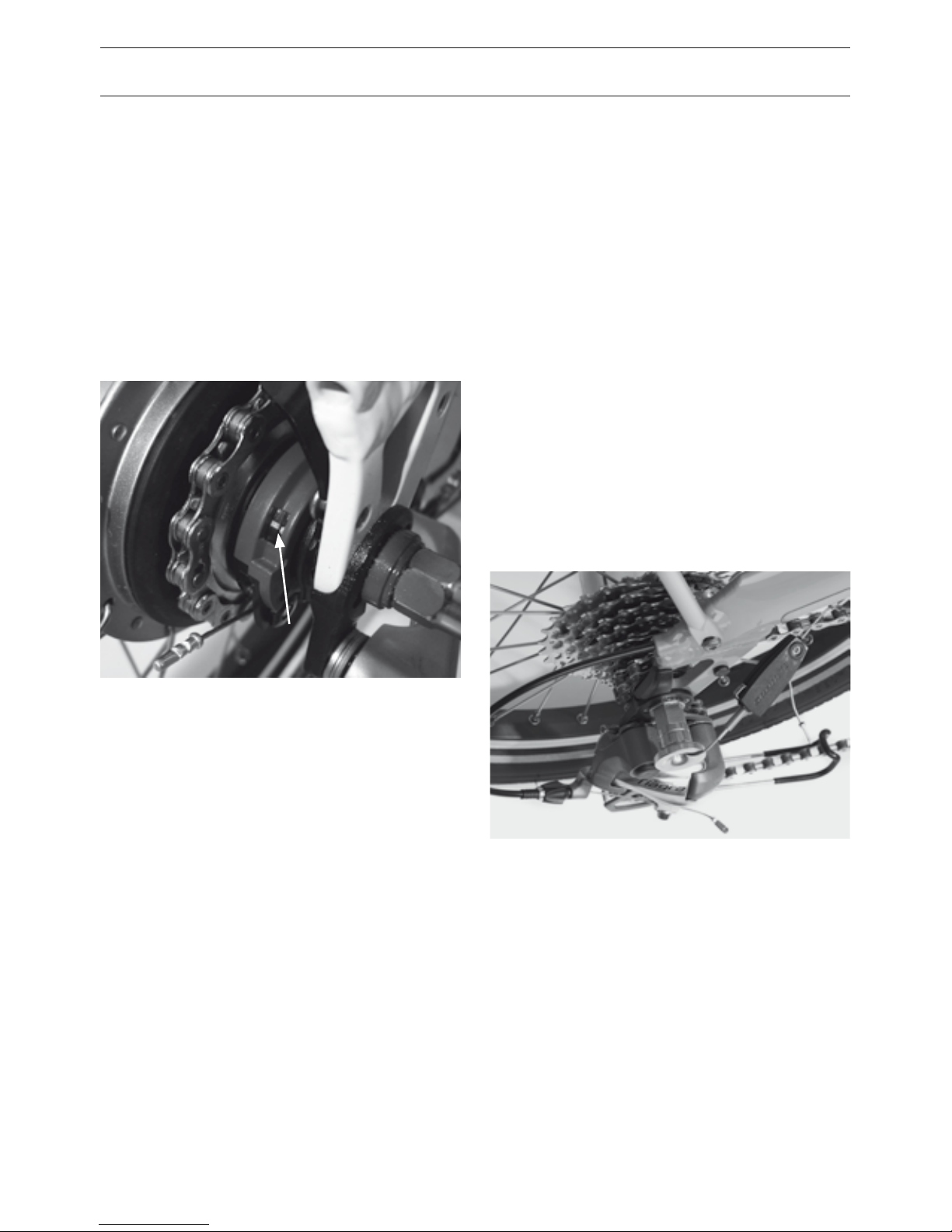
SHIMANO 8SPEED HUB
• Shift into fourth gear
• Now the two marks on the hub must be
brought into alignment. This is done using
the adjustment screw that passes through
the cable and into the shifter. By tightening
the screw, the mark moves forward and
loosening it moves the mark rearward.
Adjustment
The various gears are selected using the
shifter. The exact method varies from hub
to hub. Please contact your local dealer if
you have questions.
ROHLOFF HUB GEAR
• Please follow instructions in the manual
supplied separately from Rohlo.
3X8 DUAL DRIVE HUB GEAR
• Shift the hub gear into rst gear using the
shifter on the left side.
• With the help of the plastic box, slightly
tension the shift cable.
Page 45

43
CHAIN
CHAIN CARE
The old saying is still true: “Whoever oils well,
rides well”. The amount of lubrication is not
as important as the distribution and regular-
ity of application.
Clean your chain from time to time with a dry
cloth the removed built up dirt and oil.
Lubricate the most clean chain possible using
chain oil, grease or wax. Wax is a very
clean lubricant which is recommended for
Riese & Müller bikes.
• Turning the crank and drizzle or spray
the rollers of the chain. Rotate the chain
several times. Let the bike stand for several
minutes to allow the lubricant to penetrate
the chain.
• Finish up by wiping excess lubricant o
with a cloth to prevent it from slinging o
while riding.
CHAIN WEAR
Chains are one of the consumable parts on a
bicycle but the lifespan of the chain is deter-
mined by how the rider maintains it. Be sure
the chain is lubricated regularly, especially
after riding in the rain. Chains of derailleurs
often last from 1500 – 3000 km before need-
ing replacement. Greatly elongated chains
impair shifting and wear down sprockets
and chainrings more quickly. Replacing these
items cost much more than a chain so we
recommend changing the chain regularly.
The replacement of a chain is best left to
your dealer who has special tools to accu-
rately measure your chain and to cut your
chain to the appropriate length. Many mod-
ern chains have no chain lock and a special
tool is required to link up the two halves of
the chain. Your dealer has all of the tools that
match your chain.
TIP!
For the protection of the environment use only biodegradable
lubricants because a small amount
of lubricant always ends up on the
ground, especially during rain.
A poorly riveted chain can break
and lead to a fall. It’s best to let
your dealer replace the chain.
Be sure to use the correct chain
length when replacing the chain.
DANGER!
DANGER!
Page 46
44
WHEELS AND TIRES
The wheels on the bike keep you in contact
with the road. They experience heavy loads
during riding over irregular surfaces and
when carrying cargo. Although the wheels
are carefully manufactured and trued, they
settle in after the first few kilometers. After
a short break-in period from 200 to 400 kilo-
meters, your dealer should true the wheels
again. Regularly check the wheels but ad-
ditional tensioning is rarely necessary.
CONSTRUCTION OF A WHEEL
The wheel consists of a hub, rim and spokes.
The tire is mounted to the rim in which
the tube is inserted. Rim tape is applied to
protect the sensitive tube from the often
sharp-edged rim.
TIRES AND AIR PRESSURE
The tire provides grip and traction on the
road which is required during braking, ac-
celerating, and cornering. Furthermore, it
ensures smooth running.
Both street tires (speed, road) and knobbies
(MTB) for rough tracks are available. Tires
can only work well if it filled to the correct
air pressure. The correct inflation pressure
also prevents failures such as the crushing of
the tube especially when traveling over an
edge, the so called “snake bite”. Snake bites
are caused when going over an edge such
as a curb with a tire pressure that is too low.
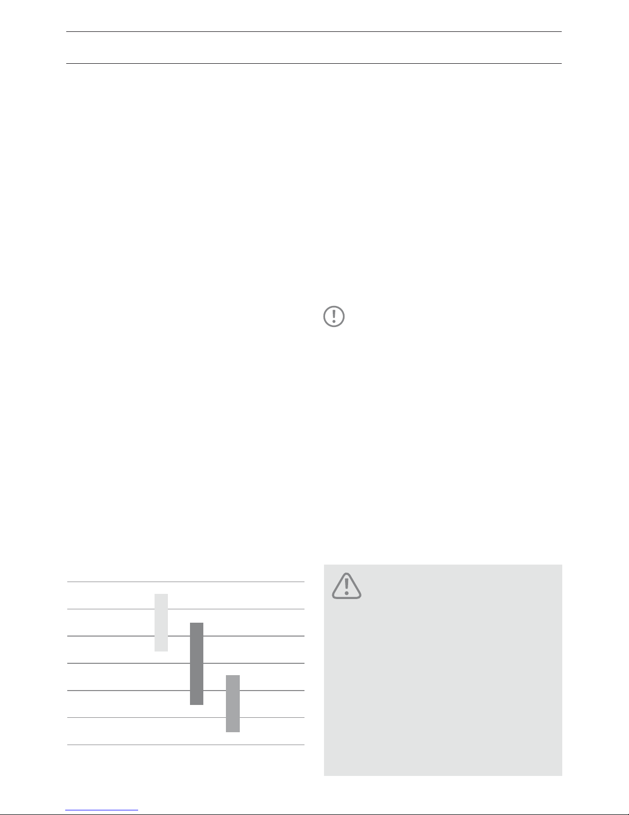
The manufacturer’s suggested pressure is
indicated on the sidewall of the tire in bar
and PSI.
PSI BAR
45 3,0
50 3,5
65 4,5
85 6,0
95 6,5
120 8,0
MTB, Big Apple
Road, Marathon Racer
Kojak
Always ride with the prescribed
air pressure and check it
regularly.
Never pump the tires over the
maximum recommended pressure rating! The tire can spring
from the rim or burst leading to
an accident!
DANGER!
TIP!
Always ride with the prescribed
air pressure and check it regularly.
Because Riese & Müller bikes are
full suspension you can always
inate the tires to the maximum
recommended pressure. This provides you the best and safest riding
position and low rolling resistance
which saves energy. Comfort is
maintained because of the full
suspension system.
Page 47
45
TUBE AND VALVE
The tire and rim alone are not airtight.
To maintain the pressure on the interior,
the tube is inserted into the tire. It is filled
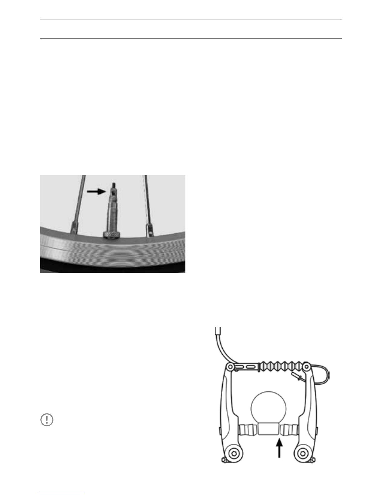
through a valve. Riese & Müller bikes use
presta valves exclusively. Before inflation,
the small knurled nut is unscrewed and
then pressed back down into the valve. It is
normal for a little air to escape during this
process.
If the presta valve is not suciently tight-
ened, this leads to the gradual loss of air.
Check the tightness of the of the valve body
in the elongated shaft. Make sure the valve
diameter matches the hole in the rim and
that the valve stands up straight.
Hand-pumps are often not suitable for
achieving high pressure. Track pumps with a
gauge are better, as you can check the pres-
sure as you pump.
CHECKING THE TIRES
Regularly check the tires. If the tread is worn
or the edges are brittle, you should replace
them. The inside of the tire may be damaged
if is contaminated by moisture or dirt. Defec-
tive rim tape must be replaced immediately.
Damage to the tires can lead to their sudden
bursting which could be dangerous.
RIM RUNOUT AND SPOKE TENSION
The spokes connect the rim with the hub in
the center of the wheel. The uniform spoke
tension is responsible for maintaining the
concentricity of the wheel. When a spoke
breaks when running over a severe bump,
the tension of the spokes is no longer in
equilibrium. Even before the rider notices the
malfunction it is aecting your bike. The side
walls of the rims no longer run parallel to
the braking surface so braking eectiveness
cannot be ensured.
TIP!
Truing wheels is a dicult business, which should denitely be
left to your dealer!
Page 48
46
WHEELS AND TIRES
Be sure to check the concentricity (runout)
from time to time. Lift the wheel from the
ground and spin it with your hand. Watch the
gap between the rim and brake pad. If this
gap changes by more than one millimeter it
needs to be trued by a professional.
WHEEL ATTACHMENT
The wheels are attached to the frame via ei-
ther an axle with a hex nut or a quick release
clamped in the dropouts.
• To remove the front wheel you have to
open the quick-release or loosen the axle
nuts for some turns.
Axle nuts
Watch the necessary tightening torque at
page 62.
Quick-release
Even though quick releases are very con-
venient, many accidents occur because of
their misuse. The correct use is described at
page 22.
Do not ride with wheels that are
out of true. The brake pad can
miss the rim sidewall and actually strike the spokes leading to
an accident!
DANGER!
Never ride a bike without rst
checking that the wheels are
securely attached to the frame
with a quick release or bolt. If
not securely attached, the wheel
could fall out during the ride and
lead to a severe injury!
DANGER!
TIP!
The quick-release lever should be
located at the right side to reduce
the folding dimensions.
TIP!
Lock your quick-release wheels
and the frame to a solid object if
you leave your bike unattended.
Page 49
47
REPAIRING A PUNCTURE
A flat tire can happen to any cyclist. A flat tire
doesn’t have to mean the end of the tour as
long as the necessary tools and spare tube/
patch kit are available.
You will need:
• Air pump
• Repair kit or spare tube
• Tire lever
• For bikes with an axle nut: 15mm wrench
• For bikes with a coaster brake or encapsu-
lated drive: 5 mm Allen wrench and 10 mm
spanner
• Latex gloves to keep chain grease o of
hands
PREPARING TO REMOVE THE WHEEL
Each model has certain things that must be
done before the wheel can be removed.
These are described below.
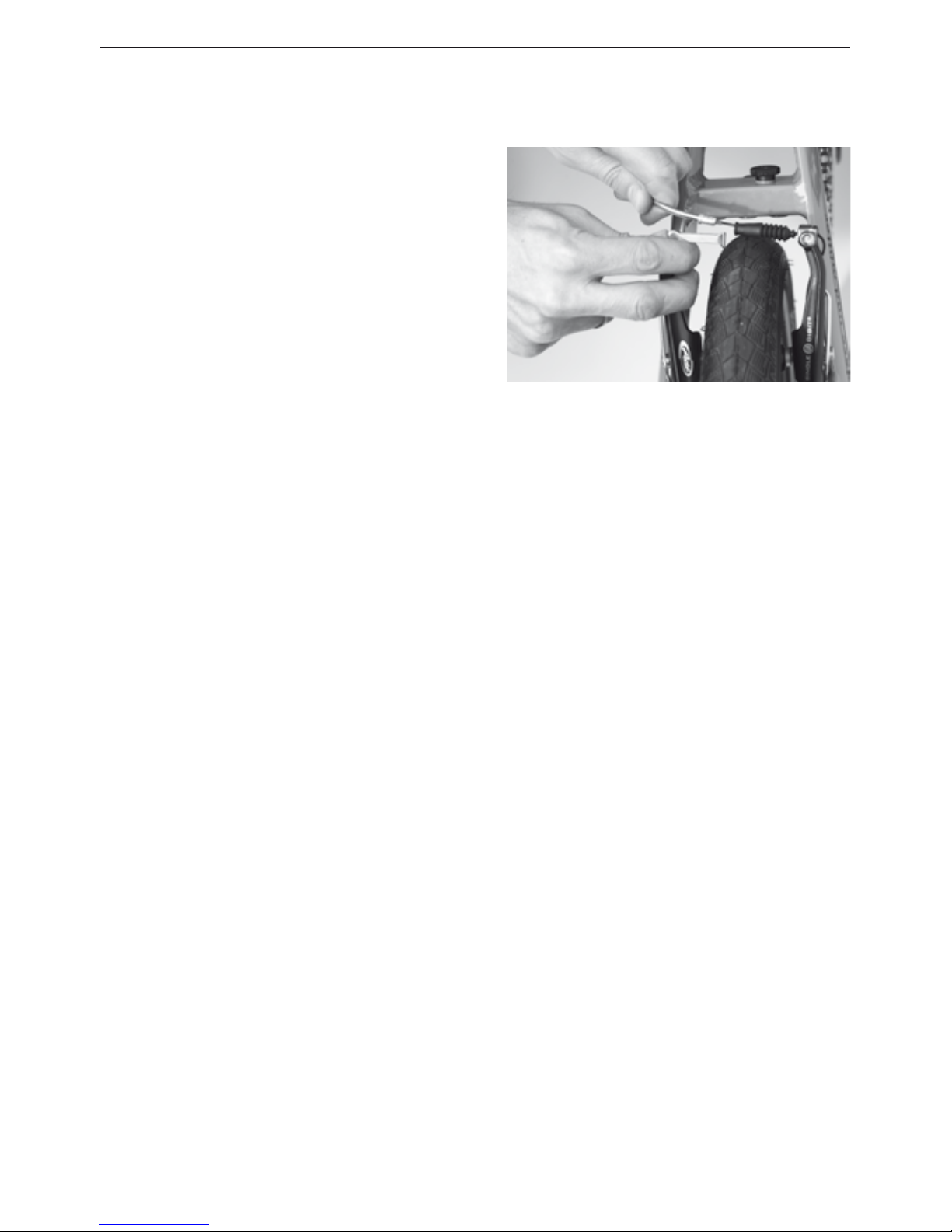
V-brakes
The brake cable must first be unhooked.
Grasp it with one hand, moving the cable
hanger (A) and the guide tube (B) with the
other hand. If the brake cable is set too tight,
you can reduce the tension by turning the
barrel adjuster on the brake lever.
• For the front brake or with Big Apple tires
we recommend opening the cable fixing
bolt at the brake arm.
Rohlo-Gear
On the Birdy Rohlo, you must also dismount
the gear box. Please see the Rohlo manual.
Derailleur gear
Before removing the rear wheel of derail-
leur systems, be sure to shift to the smallest
sprocket. Thus the derailleur is all the way to
the outside and does not hinder the removal.
Page 50
48
WHEELS AND TIRES
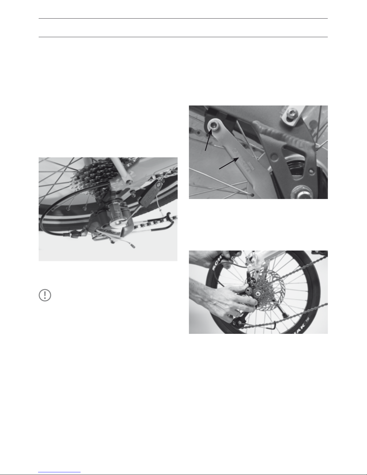
Dual Drive gear on Birdy touring
• Shift to the lowest hub gear (left shifter to
gear 1) and the highest derailleur gear (right
shifter to gear 8). The gear-change mecha-
nism (Clickbox) must be uncoupled from the
hub gear. Press on the latch C and push out
the thread rod.
• Loosen both axle nuts and remove the rear
wheel.
Internally geared hub with coaster brake
The brake arm (A) which attaches to the
frame and supports the hub while under
brake torque. Loosen the screw (B).
Rear wheels with quick-release
• Open the quick-release as described at
page 18.
• To make removal of the rear wheel easier,
you should pull the derailleur back a little
by hand.
• Lift the bike a little and give the wheel a
slap – it should fall out and down.
TIP!
If you have a puncture on the
road, you can attempt to x it
without removing the wheel, by
only removing part of the inner
tube. Leave the valve in the rim,
and rst try to nd the hole where
air is escaping, by pumping more
air into the tube. A bucket of
water or a puddle may be of some
help. Once you’ve found the hole,
check at that point on the tire and
examine it closely for the source
of the puncture. Remove this if
necessary.
A
B
Page 51
49
REMOVING TIRES
• Unscrew the valve cover and mounting
nuts and let all of the air out.
• Press the tire from the sidewall towards
the center of the rim. Do this over the
entire circumference to make removing the
tire easier.
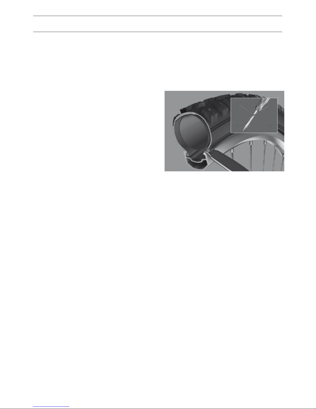
• Insert the brake levers on the right and left
side of the valve at the lower edge of the
tire and pry the rim bead over the sidewall.
Keep the lever in this position.
• Now you can remove the tube. Make sure
the valve doesn’t get caught in the rim and
that the tube isn’t damaged.
Check tire and apply patch
• Patch hole according to the instructions
from the patch manufacturer.
• If you have removed the tire, you should
also check the rim tape. It should sit evenly
and must not be cracked or damaged and
should cover all spoke holes. If you have
questions about your rim tape, please ask
your dealer.
MOUNTING TIRE
• Make sure when installing the tire that no
foreign matter such as dirt or sand gets
inside as this could damage the tube.
• Place the rim with a horn in the tire. Press
the tire sidewall completely over the rim.
This should be possible with every tire
without using a tool. Insert the valve in
the valve hole in the rim.
• Inate the tube lightly so that it assumes a
round shape. Insert it completely in the tire
being careful not to crease it.
• Begin the installation on the side opposite
of the valve. Press the tire on the rim mak-
ing sure not to pinch the tube between the
rim and the tire. Push the tube repeatedly
into the interior of the tire.
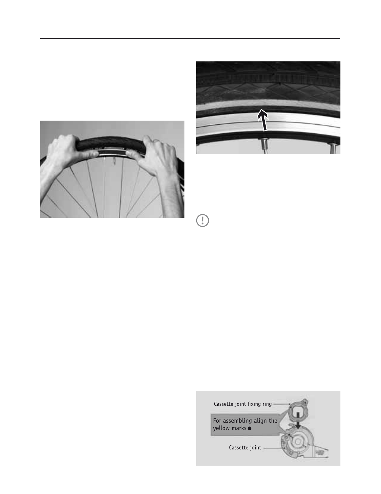
• Work both sides evenly around the circum-
ference of the wheel. Towards the end you
will need to press the tire down firmly. Pull
the already mounted portion deep into the
rim as this facilitates mounting the last few
centimeters.
© Copyright by Ralf Bohle GmbH
Page 52
50
WHEELS AND TIRES
• Check again to make sure the tube is well
seated and press the tire with your palm
over the rim bead. If this fails, you must use
tire levers. Make sure that the dull side is
facing the tube so as not to damage it.
• Press the valve into the interior of the tire
so that the tube is not pinched between
the tire and rim.
• Is the valve facing straight up? If it is not
remove one side of the tire and readjust
the tube. If you want to make sure that the
tube is not crushed under the edge, you
should halfway inflate the tire and roll it
back and forth around the circumference of
the wheel.
• Pump up the tire to the desired pressure.
The maximum pressure is indicated on the
sidewall of the tire.
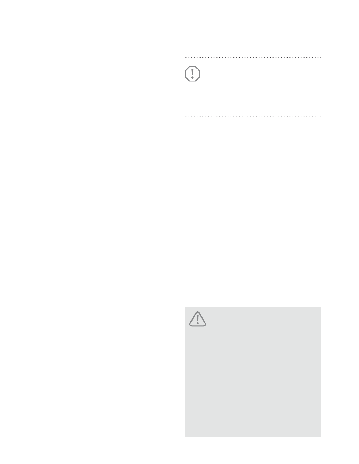
• Check the t of the tire specically the wire
(or Kevlar) bead against the sidewall of the
rim. The important thing is that the whole
tire has a uniform distance from the rim.
MOUNTING THE WHEELS
Mounting the wheels follows the reverse
procedure to their removal.
Mounting the gear arm
• For a Birdy with Shimano gear hubs the
gear arm must be assembled before
mounting the rear wheel. The lock ring
must be turned clockwise. Note the posi-
tion of the colored dots and that gear is
shifted to gear 1.
TIP!
Depending on the Birdy type it is more
dicult to remove and mount the
rear wheel as compared to a standard
bicycle. We recommend you practice
this work before the rst ride. Then it
will be easier on the road.
Page 53
51
Placing the chain on sprocket and inserting
rear wheel
• Push the rear derailleur backwards and put
the chain on the smallest sprocket
• Insert the rear wheel into the rear drop outs.
Mounting brake arm
• Mount the coaster brake arm and tighten
the bolt with a torque of 6 Nm.
Tightening wheel
• Put all washers and tabbed xing washers
in correct position onto the axle.
• Tighten axle nuts or quick-release (for
torque settings see page 62).
Checking the brake
• Re-hook the brake cable in position or
tighten it again.
• Check if the adjustment of the brake pads is
still correct.
• Check that after the repair the braking
surfaces are still free from grease or other
lubricants.
Rohlo Hub
• Mount the shifter cables (see Rohlo
manual).
Birdy touring with Dual Drive Hub
• Insert the thread rod into the plastic hous-
ing when the axle nuts are tightened. The
shifter cable should be slightly tight in first
gear.
ATTENTION!
Take care of correct position of all
washers. Incorrect positioning will
lead to malfunction.
Incorrect assembly can lead to
poor functioning or failure of the
brakes. Proceed in strict accordance with the manufacturer’s
instructions. You absolutely
must test your brakes! Errors in
mounting wheels can lead to loss
of control, and could lead to serious accidents. Incorrect positioning will lead to malfunction.
DANGER!
• Tightening torque of the axle nuts: 30Nm.
• Tighten axle nuts or quick-release (for
torque settings see page 62).
Page 54
52
The fork, stem, handlebars and front wheel
are able to rotate because of the headset
bearings. The headset must always move
easily. Large bumps or other changes can
cause the headset to loosen and develop
play.
CORRECTING PLAY IN BEARINGS
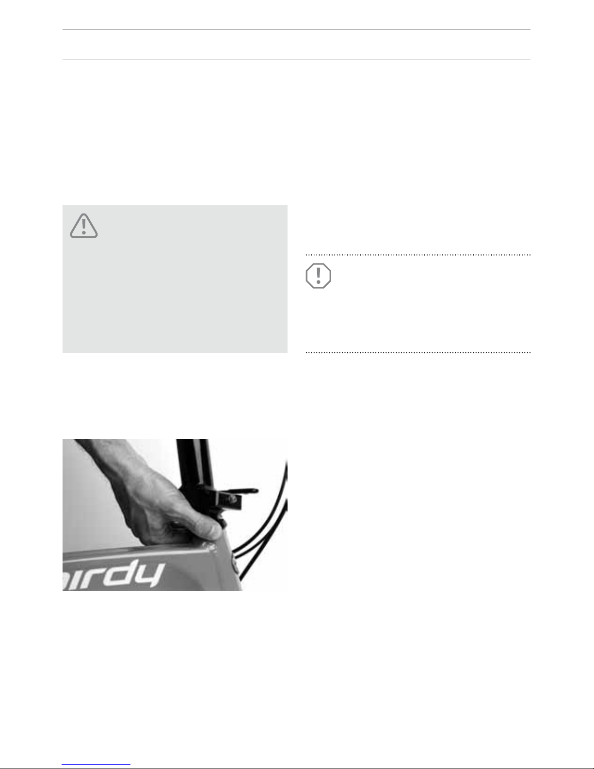
• Check the clearance by curling your nger
around the upper steering bearing shell.
• With the other hand, squeeze the front
brake and rock the bike back and forth.
• If the bearing has play in it the upper shell
will move relative to the lower shell and
you’ll detect this movement with your
finger.
FUNCTION OF THE HEADSET
• To ensure the smooth running of the
headset, grab the frame with one hand
and raise the front wheel o of the
ground. Rotate the handlebar through
its full range of motion. It should move
smoothly and without sticking through its
entire range of motion. If the handlebar is
released from your hand, it should auto-
matically return to the central position.
Riding the bike when there is
play in the headset bearings
exposes the bearing and fork to
extremely high loads which can
lead to serious damage including
fork breakage!
DANGER!
ATTENTION!
Setting the headset requires certain expertise. Therefore it is best
to leave this work to your dealer.
Page 55
53
• The play can now be adjusted out using
the recessed bolt B. Tighten this up gently
‘by feel’.
• Align the stem again so that the handle-
bars are straight.
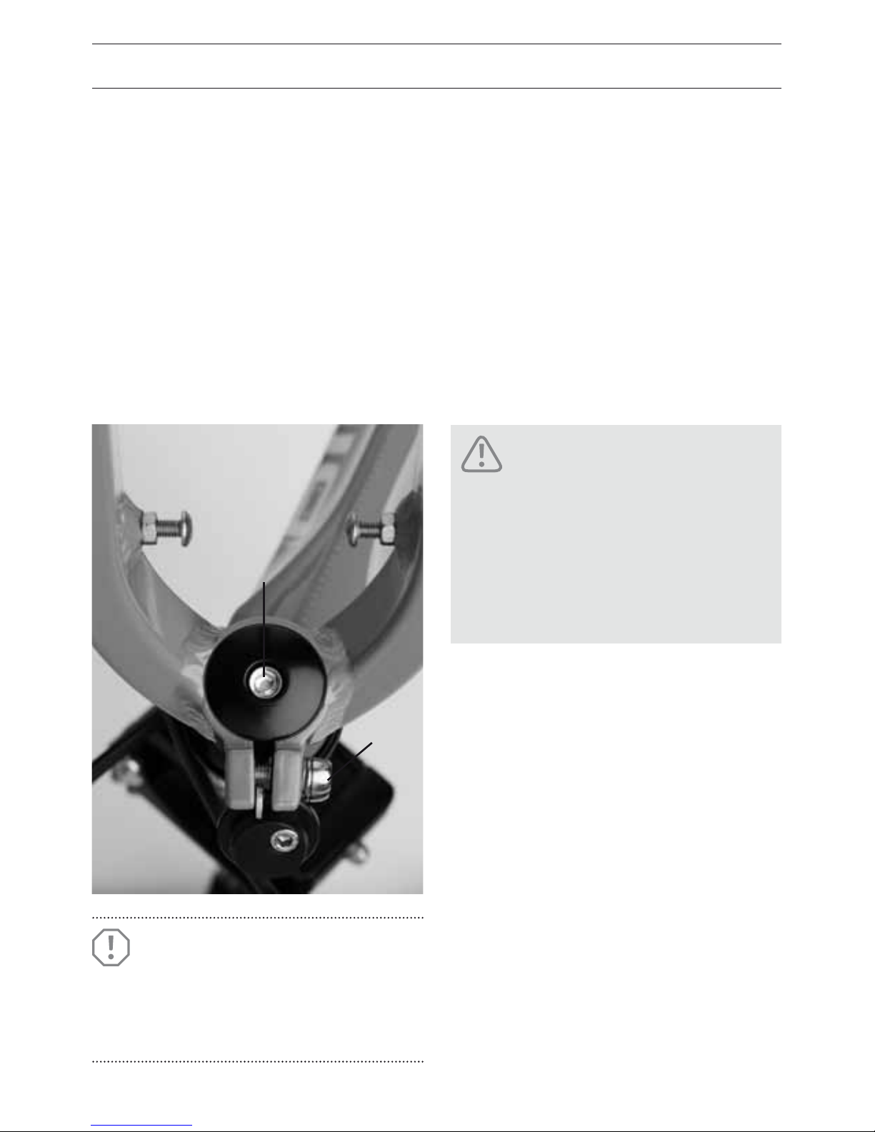
• Re-tighten the side clamp bolts A. Apply a
torque of 5 Nm.
• Carry out the test for play as described
above. Also, make sure that the bearing
isn’t adjusted too tight.
ADJUSTMENT
The headset bearings consist of an inverted
Aheadset arrangement. The ‘steerer tube’
goes from the stem hinge downwards. At
its lower end the fork pushes onto it, and is
fixed by two clamp screws A (similar to the
way an Aheadset stem is fixed). In addition,
the fork is held in place from below with a
fixing cap secured by bolt B.
• To adjust the headset, the two clamping
screws A must first be loosened.
A
B
Check that the stem is completely secure against turning
after you’ve adjusted the headset
bearings! A loose stem could
lead to a crash!
DANGER!
ATTENTION!
Do not completely tighten up this
bolt B, or you will be ‘dialing in’
play.
Page 56
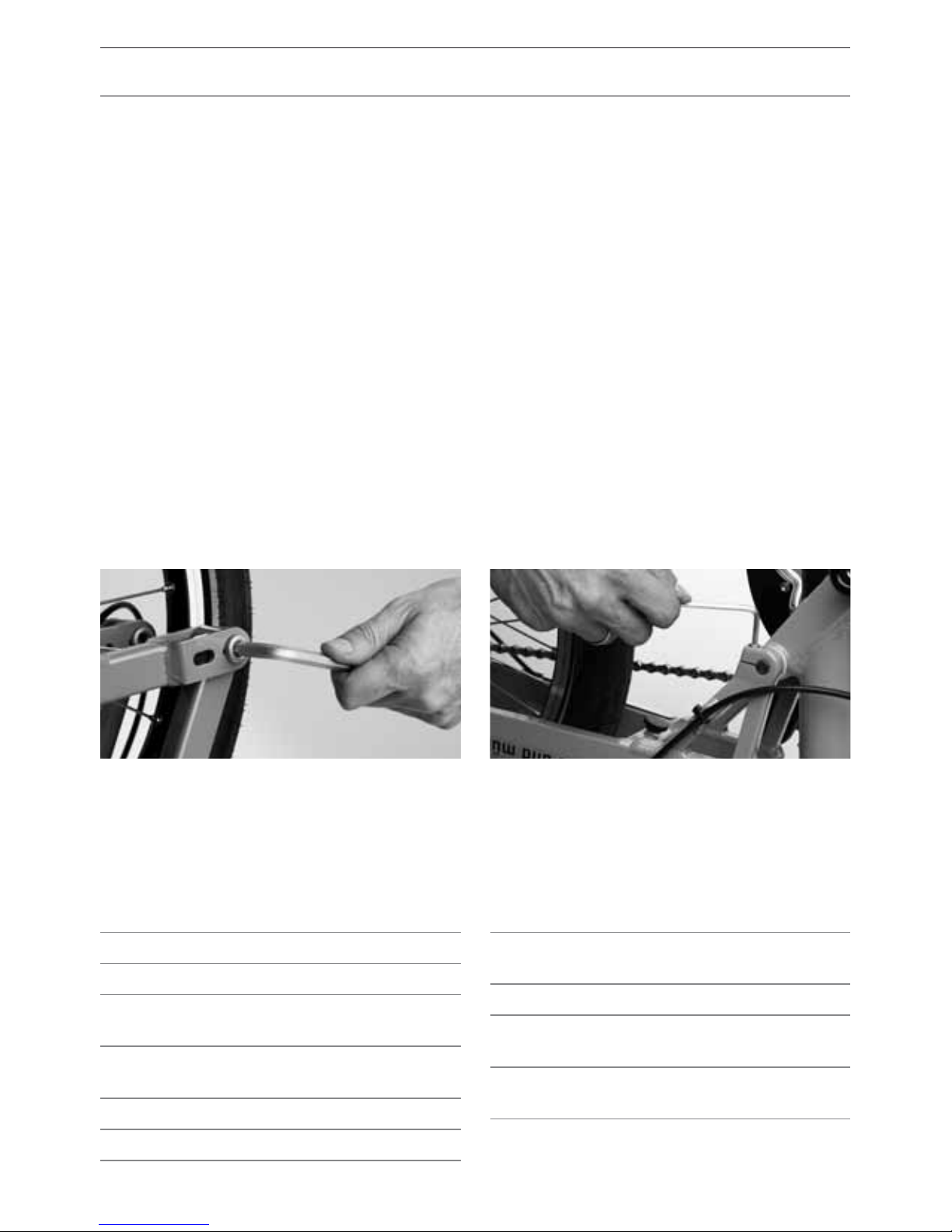
54
REAR SUSPENSION BEARINGS
The Birdy’s rear swingarm is supported on
a very precise and maintenance-free INA
sealed cartridge needle bearing, which
requires neither adjustment nor mainten-
ance. However, the position of the pivot
axle and its corresponding clamp bolts
should be checked regularly. Should the
axle have moved over to left or right, so
that it is no longer completely locked into
the swingarm on both sides, please con-
sult your dealer. The clamp bolts must be
tightened to 5 Nm torque.
SUSPENSION PIVOT BEARINGS
FRONT SUSPENSION BEARINGS
The front wheel swingarm on the Birdy is
supported by maintenance-free IGUS ‘Iglidur’
bearings. The pivot bolts can be adjusted
from the outside with an 8mm hex key. The
inner part of the bolt is secured to the fork
against rotation and cannot be moved. If the
front suspension develops play and starts
to wobble or oscillate as you ride, the outer
pivot bolt can be tightened somewhat.
If the front suspension is hard to fold, the
outer pivot bolt can be slightly loosened.
If the bearing is completely disassembled,
please secure the thread of the pivot bolt
with thread-lock adhesive.
COMPONENT
LENGHT
CABLE HOUSING
Front brake Birdy Race* 360 + 780 mm
Rear brake Birdy Race* 360 + 1200 mm
Shifter cable front
derailleur Birdy Race*
360
+ 920 mm
Shifter cable rear
derailleur Birdy Race*
360 + 920
+ 550 mm
Front brake 1300 mm
Rear brake 1300 mm
COMPONENT
LENGHT
CABLE HOUSING
Shifter cable
rear derailleur
1250
+ 550 mm
Shifter cable Birdy city 1530 mm
Shifter cable hub
gear Birdy touring 1530 mm
Shifter cable hub
gear Birdy rohlo 1530 mm
CABLE LENGTH
The table helps you to find the right length when replacing shifter and brake cables.
* Values are only valid for fix stem for adjustable
stems an additional 150 mm must be added.
Page 57

55
LIGHTING SYSTEM
RETROFITTING LIGHTING SYSTEM
If you would like to upgrade to a newer light-
ing system, please contact your dealer.
Operating lighting system
• Some lights are equipped with a photocell
which turns the lights on automatically at
dusk (switch position “S”).
• You can also operate the lighting manually
(switch position “on” and “o”).
• Some lights with only an “on” and “o”
switch.
• Before each ride ensure your lighting
system is working correctly. Also check for
loose wires or connections.
LOCATING DEFECTS
• Visually inspect the entire length of the
wire for damage. Verify all of the contact
points are intact. Often connections are
corroded by salt water or rain. Unplug the
power cord and plug it back together.
• Verify the correct polarity. The light wire is
the ground wire.
HEADLIGHT ADJUSTMENT
The center of the front light’s beam should
hit the road at a maximum of 10 meters in
front of the bike.
FUNCTION OF THE LIGHTING SYSTEM
To safely use roadways a functioning light-
ing system is mandatory (see page 7). You
should know how the system operates so
that you can resolve and any problems that
might arise. Diculties sometimes arise if
you ride in the rain a lot or in the winter. The
dynamo generates the current necessary to
power the lights. There is a cable connecting
the dynamo to the front light. In the front
there is a light switch for controlling lighting.
From the front light there is a cable going to
the tail light.
HUB DYNAMO
Many Birdys are fitted with a hub dynamo
that works regardless of weather conditions.
Another advantage of hub dynamos is that
they are more ecient than side runner
dynamos. This means the power required to
generate electricity is lower.
TIP!
Read more about lighting on page 9.
Page 58

56
GENERAL CARE/INSPECTIONS
ROUTINE MAINTENANCE
The bike you have purchased is a very high
quality product. When you pick the bike up
from the dealer, he has already made the
bike ready for you to ride. Nevertheless the
bike does require some routine maintenance
which is best performed by your dealer. Only
then can the safe operation of all parts be
guaranteed. This will keep you riding happily
and safely for many years.
Washing and caring for your bike
Dried sweat, dirt and salt from winter riding
or from sea air can harm your bike. There-
fore we recommend regularly cleaning and
corrosion protection of all susceptible bike
components. The easiest way to remove dirt
and salt is using a pressure washer but this
method has serious disadvantages, the high
pressure stream of water can push past the
seals and into the interior of the bearings.
This dilutes the lubrication which increases
friction that ultimately destroys the bearing
surfaces and the smooth functioning of the
bearing. Also, decals are often accidentally
blown o by the powerful stream.
A much more gentle way to wash the bike is
with a gentle spray of water or a bucket of
water and a sponge/brush.
Cleaning by hand
has another positive side eect. You can de-
tect paint damage, worn parts, loose spokes
other defects early.
As part of this regular maintenance, you
should check tire pressure, light and brake
functions and examine the bike for damage.
ATTENTION!
Only perform maintenance tasks
for which you have the appropriate tools and expertise.
ATTENTION!
Do not clean your bike using a
pressure washer or steam cleaner
at close range.
TIP!
Protect areas where cables could
touch paintwork, such as underneath the chainstays, with a
plastic lm or similar. This avoids
unsightly scratches and damage to
paintwork.
TIP!
Protect the bottom of the chainstay and the places where the cables could chafe to avoid unsightly
scratches.
Page 59
57
Protecting the finish
After the bike is dried, you should protect the
paint and metallic surfaces with a hard wax.
Also protect spokes, hubs bolts and nuts, etc
with a wax film. Polish the waxed surfaces
with a soft cloth so that they shine and repel
water.
Caring for anodized surfaces
The aluminum parts of your Riese & Müller
bike are protected by a special anodizing
process during which an electrochemical pro-
cess generates a special protective layer. This
layer is very hard and therefore relatively
resistant to scratches. Despite the positive
attributes the anodized coating requires
care. Clean with water and if necessary use
mild detergents to dissolve grease. Dry and
apply a special anodized surface treatment
(available from your local dealer) with a soft
cloth which helps remove paint, tar and oil
residue. Lastly rub the parts with a soft,
clean cloth to remove excess treatment and
repel dust
Polished aluminum surfaces (Birdy disc)
The Birdy disc has a high polished and
compacted surface which is quite resistant
to oxidation. After a certain time it may be
necessary to polish the surface with the en-
closed polish to maintain a perfect surface.
This natural oxidation poses no technical
issues and does not indicate material failure.
ATTENTION!
While cleaning look for cracks,
scratches, dints, or discolorations.
If in doubt, contact your local dealer and let them replace damaged
components and touch up damaged paint.
TIP!
After cleaning it is recommended
to lubricate the chain if necessary
(see page 43).
To avoid rust, apply a little spray
wax to all screw heads.
Ensure no lubricant or wax contaminates the braking surfaces
of the disc brakes! Imminent
brake failure could cause an
accident!
DANGER!
Page 60

58
STORING YOUR BIKE
If you regularly maintained your bike during
the season, you won’t need to perform any
special preparations to store it on a short
term basis. It is recommended to store the
bike in a dry, well-ventilated area.
Overwintering your bike
When storing your bike for the winter, there
are some things to consider:
• During extended storage the tires may
gradually lose air. If the tire remains flat for
an extended period, it could damage it.
• Clean the bike and protect it against corro-
sion as previously described.
• Store the bike in a dry place.
• Switch the derailleur to the smallest
sprocket so the cables and springs are as
relaxed as possible. For Shimano hub gears,
shift to the first gear.
INSPECTIONS
A regular check of the bike guarantees long
term function and enjoyment. As with a car,
annual inspections can help prevent costly
repairs. The adjustment of the bearings or
shifting system and the timely exchange of
worn parts can prevent severe damage to
the operating parts of the bicycle. After the
initial break-in period, you should have your
bike inspected at regular intervals.
The recommended service intervals listed in
the table in the appendix (page 64 – 65) are
intended for riders who ride between 1,000
and 2,000 miles per year. When riding more
or on poor roads/o-road, these intervals
are shortened. This also applies to taking
frequent trips in the rain or in a generally
humid climate.
GENERAL CARE/INSPECTIONS
TIP!
In the winter months when most
bike dealers aren’t very busy, many
shops offer special priced annual
checks. Take advantage of these
seasonal offers and bring your bike
to the dealer for inspection.
ATTENTION!
After 200 – 400 km, but no later
than three months, bring your bike
back to the dealer for an initial
inspection.
Page 61

59
Your dealer is legally required to provide a
bike that is not defective, of reduced value
or suitability. Your right to claims ends after
two years from the date you accept delivery
of the bike from the dealer. Notwithstand-
ing the statutory warranty of quality, we
also provide you a ten year warranty against
frame or swingarm breakage. Extended war-
ranty claims are only valid if the following
conditions are met:
• You are the original owner of the bike
• Within four weeks of your purchase, you
have registered your bike in our online sys-
tem: http://en.r-m.de/registration/
• The service record in the appendix is com-
pleted and all required inspections were
performed and noted by the dealer.
In case of damage, the completed service
record must be submitted along with the
frame or the complete bike. Therefore pro-
tect these important documents. If all criteria
are met, then we will replace the defective
item but shipping and labor will be charged
to the customer. This warranty only applies
to the original buyer. Further claims such as
damages or other losses are not covered.
Any warranty claims do not extend the origi-
nal warranty period. Damages due to wear
and tear, neglect (insucient maintenance),
jumping, overloading or amateur assembly
or modifications (additions to or alterations
of existing components) are not covered.
Damages caused by competitive racing,
jumping or other types of overstressing are
not covered.
Battery
The battery of your Birdy hybrid is a consum-
able item; the electronic components of the
system are subject to the two year statutory
warranty. We provide a voluntary guarantee
for the complete battery for one year. We
guarantee that the battery after a year or
500 charging cycles (whichever comes first)
will still have a residual caparity of 70%. Even
a “used” battery, which perheps has only
a residual capacity of 65%, can be used for
a long time with stable performance. The
battery should last over 1000 charge cycles
without a problem.
WARRANTY/GUARANTEE
ATTENTION!
The dealer must ensure the bike
is roadworthy in order to validate
the functional warranty. The dea-
ler conducts a nal quality check
and performs a test ride.
Page 62

60
INFORMATION REGARDING WEAR
Some parts of your bike are subject to func-
tional wear. The amount of wear depends on
the maintenance of the bike and the riding
conditions (mileage, riding in the rain, dirt,
salt, etc.). Bicycles that are often stand-
ing outside in the weather are subject to
increased wear. These parts require regular
maintenance and care but will (depending
on the intensity of use and riding conditions)
eventually reach the end of their useful life.
These parts must be replaced when they
reach there wear limit.
These include:
• chain
• brake cables
• grips
• chain ring and sprockets
• shift cables
• tires
• saddle cover
• brake pads
• rims
• lament (lights)
The pads or rim and disc brakes are subject
to functional wear. Sporty use or riding in
mountainous terrain shortens the life of the
pads. Check the pads regularly and replace
them as needed. You can acquire replace-
ments from your local dealer.
Rim brakes not only wear out the pad but
also the rim itself. Therefore check the rim
regularly such as when inflating the tire.
The sidewall of the rim contains a groove
that functions as a wear indicator. When this
groove is no longer visible, the rim must be
replaced. If deformations or fissures in the
rim sidewalls occur when inflating the tire,
the rim has reached the end of its service life
and needs to be replaced.
The bearings and seals in suspension forks
and rear swingarms are always in motion
when the suspension is activated. Envi-
ronmental conditions such as rain, dirt, etc.
cause these moving parts to wear out.
These areas must be cleaned and regularly
maintained. Depending on the operating
conditions it is possible that these parts may
need to be replaced due to wear such as the
development of bearing play.
Your point of contact for claims and services
is the dealer from which you purchased the
bike. Upon request we can refer you to your
nearest dealer (dealers can also be found on
our website www.r-m.de). Additionally, we
recommend that you contact your dealer to
ensure the fastest and most cost-eective
solution. Please note that if your bike is
sent to us by your dealer for repair: the bike
must be suciently clean before repairs can
take place. Remove any accessory items like
computers, mirrors, trailer hitches, locks, etc.
prior to shipping.
Service is only performed on the original
standard equipment. Individual modifica-
tions will be restored to the original standard
equipment. In the context of service no worn
out parts will be replaced and no inspections
Page 63

61
carried out. In addition, payments and ma-
terials are handled exclusively through our
dealers. Ensure that either you or your dealer
includes sucient postage.
To ensure a long service life the components
must be installed to the manufacture’s
recommended torque specifications and the
recommended service intervals must be
strictly adhered to.
Failure to comply with the installation re-
quirements and inspection intervals voids
the warranty. Please note that actions/
inspections outlined in your instruction
manual may dictate the replacement of
safety related components such as handle-
bars, brakes, etc.
Page 64

62
PART THREADED COMPONENT TORQUE
Rear derailleur Mounting bolt
Cable clamp bolt
Jockey wheel bolts
8–10 Nm
4–6 Nm
3–4 Nm
Twist-grip Securing bolt (hex key) 1–2 Nm
Brake lever Securing bolt (hex key) 5–6 Nm
Hub Brake /
Internal Gear Hub
Brake reaction arm at frame
Locknut for bearing adjustment (quick-release hubs)
Axle nut for hub gears
Dual drive hub
4–5 Nm
10–25 Nm
40–45 Nm
30 Nm
Freehub body Freehub body securing bolt
Freehub body securing nut
Cassette lockring
35–49 Nm
35–44 Nm
29–49 Nm
Crankset Crank bolt 35 Nm
Sealed-bearing bottom bracket Housing 49–69 Nm
V-brakes Brake socket bolts
Cable clamp nut
Brake shoe fastening bolt
5–9 Nm
6–8 Nm
8–9 Nm
Seatpost Saddle rail clamp bolts
9–12 Nm
Rear swingarm Clamp bolts 5 Nm
Front swingarm Fork clamp bolt to ‘steerer tube’ 5 Nm
Stem hinge Nut M5 for tension rod
Bolts M4x16 for reaction point Tension rod
Bolt M4x10, left side, Loctite
Bolt M4x10 at clamp, Loctite
2–3Nm
2–3 Nm
1 Nm
1 Nm
Stem Handlebar clamp bolt 12–14 Nm
Bar ends Clamp bolts See
manufacturers’
instructions
TORQUE SETTINGS
Page 65

63
Page 66

64
PART JOB
BEFORE EVERY RIDE MONTHLY ANNUALLY SPECIAL INTERVALS
Lighting Check mounting screw
Tires
Check air pressure
Check tread and sidewall
Brakes Check lever travel, pad thickness
and position on rim
Brake cables Visual check
Brake housing Inspect for leaks
Stem hinge Hinge lever closed?
Rims, Aluminium Check sidewall thickness /
wear indicator (possibly replace)
Bottom bracket Check bearing for play
Chain check
Lubricate if necessary
Change if necessary
Chain (hub gear)
Check chain tension
Oil chain
Crank check Re-tighten if necessary
Paint Protect
Wheels/spokes Check trueness and spoke tension
Handlebar, Aluminum Visual check
Replace
Headset
Check bearing play
Re-grease
Metallic surfaces Wax (not at rims)
Hubs Check for bearing play, lubricate
Pedals Check for bearing play, lubricate
Quick release Check, re-tighten if necessary
Nuts and bolts Check, re-tighten if necessary
Valves Check
Front swingarm catch Check for play and proper functioning
Rear swingarm catch Check for play and proper functioning
Stem hinge Check for play, grease
Stem and steerer Visual check
Replace
Front swingarm
Check for play
Replace
Brake and gear cables Disassemble, re-grease or replace
SERVICE AND MAINTENANCE PLAN
The jobs marked • you
can carry out yourself,
provided that you have
a certain amount of
mechanical competence,
experience, and suit-
able tools (for example, a
torque spanner).
If any checks indicate
something wrong, take
suitable remedial meas-
ures immediately.
If you are in any doubt, or
if something is unclear,
please consult your
dealer.
The jobs marked
✖ should
be carried out only by
your dealer.
1
After crash or 10.000 km or 3 years
(whichever comes first).
Page 67

65
BEFORE EVERY RIDE MONTHLY ANNUALLY SPECIAL INTERVALS
•
•
•
•
•
•
•
✖ after the second set of
brake pads
at the latest
✖
•
✖
After 1.500 km
• Every 1.000 km
•
Every 3 months
✖
• At least every 6 months
•
•
✖
1
•
✖
•
✖
✖
•
•
•
✖
✖
✖
•
✖
1
✖
✖
At least every 20,000 km
✖
Page 68

66
DOCUMENTS
In the appendix of this manual you’ll find:
• the Riese & Müller service record which
should be filled out by your dealer after
each inspection/service. In case of a war-
ranty claim this record and a copy of the
proof of purchase must be submitted to
Riese & Müller. All of the service must be
completed by an authorized/ registered
dealer.
• a service and maintenance schedule can be
found on pages 64 – 65.
• a list of torque settings for all of the critical
parts of your bike can be found on page 62.
The dealer requires these for repairs and
inspections.
Enclosed you’ll find
• the instruction manuals of various compo-
nent manufacturers which contain detailed
information and instructions. There you
can also find details on use, maintenance
and care. Make sure to keep the instruction
manuals together with this manual.
• the instruction manual for E-bike technol-
ogy.
• proof of purchase, which proves that you
are the first owner and how long you have
owned it.
We hope your bike will always provide a
good ride. Should any issue occur, please
contact your dealer for further assistance. In
case of additional problems that your dealer
cannot resolve, you can call us at any time.
Your Riese & Müller Team
ATTENTION!
As the rst owner of the bike please ll in the service record in the
appendix and have all inspections/
service listed in there by an
authorized/registered dealer.
Page 69

67
SERVICE RECORD
Please have your authorized/registered dealer include all
inspections performed on your bike in this service record.
The extended warranty is only valid if you have registered
your bike within four weeks of the purchase, can provide a
completed service record (by authorized/registered dealers)
and proof of purchase.
Model:
Color:
Number of gears:
Frame number:
Date of purchase:
The transfer was made:
City:
Date:
Dealer stamp
Signature of dealer:
Page 70

68
SERVICE RECORD
1st Inspection
Within 3 months of purchase
or within the first 400km:
Replaced or repaired parts:
Order number: Date:
Stamp/Signature of dealer:
2nd Inspection
Within one year of purchase
or within the first 2000km:
Replaced or repaired parts:
Order number: Date:
Stamp/Signature of dealer:
3rd Inspection
Within two years of purchase
or within the first 4000 km:
Replaced or repaired parts:
Order number: Date:
Stamp/Signature of dealer:
Page 71

69
4th Inspection
Within three years of purchase
or within the first 6000 km:
Replaced or repaired parts:
Order number: Date:
Stamp/Signature of dealer:
5th Inspection
Within four years of purchase
or within the first 8000 km:
Replaced or repaired parts:
Order number: Date:
Stamp/Signature of dealer:
6th Inspection
Within five years of purchase
or within the first 10000 km:
Replaced or repaired parts:
Order number: Date:
Stamp/Signature of dealer:
Page 72

70
SPACE FOR NOTES
Page 73

riese und müller GmbH
Feldstraße 16
64331 Weiterstadt
Germany
www.r-m.de
Tel.: +49 61 51-366 86-0
Fax: +49 61 51-366 86-20
All current instruction
manuals can be found at
www.en.r-m.de/infocenter/downloads/
Or simply scan the QR code with
your smartphone.
 Loading...