

Page 1
SAFE FLEX
riese electronic gmbh
Junghansstraße 16
D-72160 Horb a. N.
Tel. +49-(0)7451-5501-0
Fax. +49-(0)7451-5501-70
www.automation-safety.de
Zielgruppe/
Target audience
Zeichenerklärung/
Explanation of
signs
Einleitung
Diese Betriebsanleitung soll Sie mit dem
Sicherheitsrelais SAFE FLEX vertraut
machen.
Die Betriebsanleitung richtet sich an folgende Personen:
• Qualifizierte Fachkräfte, die Sicherheitseinrichtungen für Maschinen und Anlagen planen und
entwickeln und mit den Vorschriften über Arbeitssicherheit und Unfallverhütung
vertraut sind.
• Qualifizierte Fachkräfte, die Sicherheitseinrichtungen in Maschinen und Anlagen einbauen
und in Betrieb nehmen.
In dieser Betriebsanleitung werden einige
Symbole verwendet, um wichtige Informationen hervorzuheben:
Dieses Symbol steht vor Textstellen, die
unbedingt zu beachten sind. Nichtbeachtung führt zur Verletzung von Personen
oder zu Sachbeschädigung.
Dieses Symbol kennzeichnet Textstellen,
die wichtige Informationen enthalten.
Dieses Zeichen kennzeichnet auszuführende Tätigkeiten.
Nach diesem Zeichen wird beschrieben,
wie sich der Zustand nach einer ausgeführten Tätigkeit ändert.
© Copyright Alle Rechte vorbehalten.
Änderungen, die dem technischen Fortschritt dienen, vorbehalten.
SAFE FLEX
Original Bedienungsanleitung
Sicherheitsschaltgerät für Not-Haltund Schutztüranwendungen, ZweiHand-Relais, Nachschaltgerät für
Lichtschranken, Lichtgitter und taktende Sicherheitsschalter
Original operating instruction
Safety controller for e-stop and gate
monitoring applications, two hand
control, Safety controller for light curtains, light barriers and for pulsed
safety switches
Introduction
This operating instruction will make you
familiar with the safety relay SAFE FLEX.
The operating instruction is addressed to
the following persons:
• Skilled personnel, who plan or
develop safety equipment for
machines and plants and are familiar with the safety instructions
and safety regulations.
• Skilled personnel, who install
safety equipment in machines
and plants and put them into operation.
The operating instruction contains several symbols which are used to high-light
important information:
This symbol shows text passages which
should be noticed. Non-observance leads
to serious injuries or damage of property.
This symbol shows passages which contain important information.
This sign is placed for activities.
After this sign it is described how the
state changes after an executed activity.
© Copyright All rights reserved.
Changes, which serve technical improvements, are reserved.
070311 1
Page 2
SAFE FLEX
Bestimmungsgemäße
Verwendung /
Intended application
Zu Ihrer Sicherheit/
For your safety
Sicherheitshinweise
Das Sicherheitsschaltgerät SAFE FLEX
ist bestimmt für den Einsatz in:
• zweikanaligen Not-Halt- oder
Schutztür-Einrichtungen
• Zwei-Hand-Applikationen
• als Nachschaltgerät für Licht-
schranken, Lichtgitter und taktende Sicherheitsschalter
Personen- und Sachschutz sind nicht
mehr gewährleistet, wenn das Sicherheitsrelais nicht entsprechend seiner
bestimmungsgemäßen Verwendung eingesetzt wird.
Beachten Sie unbedingt die folgenden Punkte:
Das Gerät darf nur unter Beachtung dieser Betriebsanleitung von Fachpersonal
installiert und in Betrieb genommen werden, das mit den geltenden Vorschriften
über Arbeitssicherheit und Unfallverhütung vertraut ist. Elektrische Arbeiten
dürfen nur von Elektrofachkräften durchgeführt werden.
• Beachten Sie die jeweils gültigen
Vorschriften, insbesondere hinsichtlich der Schutzmaßnahmen.
• Reparaturen, insbesondere das
Öffnen des Gehäuses, dürfen
nur vom Hersteller oder einer
von ihm beauftragten Person
vorgenommen werden. Ansonsten erlischt jegliche Gewährleistung.
• Vermeiden Sie mechanische Erschütterungen größer 10g (16
ms) beim Transport oder 4g (10200 Hz) im Betrieb.
• Montieren Sie das Gerät in einem staub- und feuchtigkeitsgeschützten Gehäuse (IP54 oder
besser). Staub und Feuchtigkeit
können zu Funktionsstörungen
führen.
• Sorgen Sie für eine ausreichende Schutzbeschaltung bei kapazitiven und induktiven Lasten an
den Ausgangskontakten.
• In regelmäßigen Zeitabständen
sollte das Relais ausgelöst werden und auf richtige Funktion
geprüft werden (mindestens jedes halbe Jahr oder im Wartungszyklus der Anlage).
Safety indications
The safety control device SAFE
FLEX can be used for:
• dual-channel emergency stop or
gate monitoring applications
• two hand applications
• safety lightcurtains, safety light-
barriers and pulsed safety
switches
Operator and object protection isn’t guaranteed, if the safety relay isn’t be used by
the defined application.
Please pay attention to the following
points:
The device must only be built in and operated by specialised staff, which is familiar with this instruction and the current
regulations for safety at work and accident prevention. Working on electrical
equipment is only allowed for specialised
staff.
• Pay attention to valid regulations,
particularly in reference to preventative measures.
• Any repairs have to be done by
the manufacturer or a person
which is authorised by the manufacturer only. It is prohibited to
open the device or implement
unauthorised changes, otherwise
any warranty expires.
• Avoid mechanical vibrations
more than 10g (16 ms) during
the carriage and more than 4g
(10-200 Hz) during operation.
• The unit should be panel
mounted in an enclosure rated at
IP 54 or better, otherwise dampness or dust may lead to malfunction.
• Adequate fuse protection must
be provided on all output contacts with capacitive and inductive loads.
• The safety relay should be tested
in a defined time period (every
six months or after each check of
the plant).
070311 2
Page 3
SAFE FLEX
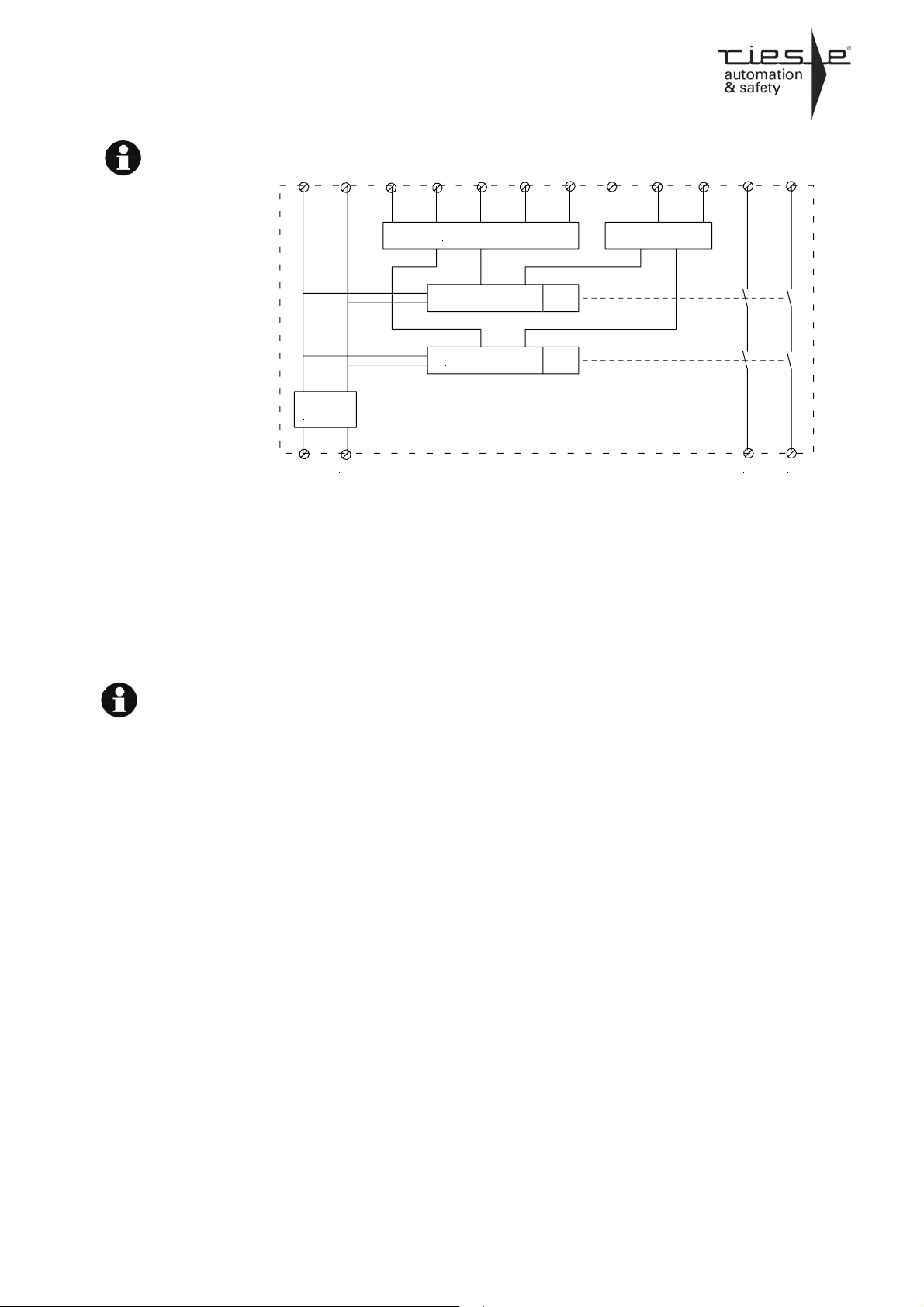
Blockschaltbild
Function diagram
S11, S21
S12, S22
S32,S33,S34
S35,S36
13-14, 23-24
S31
Aufbau und Funktionsweise/
S33 S36 S12 S31 13 23
POWER
A1
A2
Aktivierungsausgänge (getaktet)
Sicherheitseingänge
Startkreise
Betriebsartwahl
Freigabestrompfade
Hilfsausgang (SPS etc.)
Die Aktivierungs- und Eingangskontakte,
die Starteingänge und die Betriebswahlklemmen sind entsprechend des Verwendungszweckes zu verdrahten (s.
„Montage und Inbetriebnahme“).
Die Aktivierungsausgänge S11, S21 des
Gerätes sind kurzschlussfest. Sie werden
getaktet und von den internen Kontrollern
unabhängig überwacht.
Im inaktiven Zustand leuchtet nur die
Power-LED - die Relaiskontakte sind
offen. Das Aktivieren der Sicherheitseingänge wird durch die LEDs IN1 und IN2
signalisiert. Wird nun der Start aktiviert,
leuchten die LEDs CH1, CH2 und die
Relaiskontakte S13-S14 und S23-S24
sind geschlossen. Liegt eine Störung vor
dann leuchtet die Fault LED.
INPUT CIRCUIT
Mikrocontroller 1 K1
Mikrocontroller 2
Assembly and function
S11 S21S32S22 S34 S35
OUTPUT CIRCUIT
K2
Activation outputs (clocked)
Safety inputs
Start circuits
Operating mode select
Safety relay outputs
Auxiliary output (PLC etc.)
The activation and input contacts need to
be wired according to the intended purpose (see "Mounting and start-up").
The activation outputs S11 and S21 of
the device are short-circuit-proof. The
output signals are clocked and independently monitored by the internal controllers.
At inactive state only the Power LED is lit
- the safety outputs are open. The activation of the safety inputs is signalized by
the LEDs IN1 and IN2.
After starting, the LEDs CH1 and CH2
are lit - the safety outputs S13-S14 and
S23-S24 are closed.
In the case of a malfunction the Fault
LED is lit.
14 24
070311 3
Page 4
SAFE FLEX
Mechanische Montage
Mechanical mounting
Elektrischer Anschluss
Electronic connection
Montage und Inbetriebnahme
Für eine sichere Funktion muss das NotHalt-Sicherheitsrelais in ein staub- und
feuchtigkeitsgeschütztes Gehäuse (IP54
oder besser) eingebaut werden.
• Montieren Sie das SAFE FLEX
auf eine Normschiene
Führen Sie die Verdrahtung entsprechend des Verwendungszweckes durch.
Orientieren Sie sich dabei an den Anwendungsbeispielen weiter unten. Generell ist das Sicherheitsrelais nach folgenden Angaben zu verdrahten:
1. Aktivierungs- und Rücklesekreis schließen
• Achtung: Der Rücklesekreis
(Brücke oder Öffnerkontakte der
externen Schütze in Reihe) wird
bei Autostart über die Klemmen
S33–S32 und beim überwachten
Start über die Klemmen S33–
S34 geschlossen.
• Autostart ohne Überwachung:
Rücklesekreis S33 und S32 verbinden.
• Überwachter Start: Starttaster
zwischen die Klemmen S33 und
S32 und eine Brücke oder die
Öffnerkontakte der externen
Schütze in Reihe zwischen S33
und S34 anschließen.
2. Betriebsart wählen
2.1 Betriebsart Not-Halt und Schutztürwächter:
(2-kanalig, mechanische Kontakte,
unendliche Gleichzeitigkeit): Die Sicherheitskontakte des Auslöseelementes an S11-S12 und S21-S22
anschließen. Die Klemmen S35-S36
überbrücken.
Im Betriebsmodus Not-HaltSchaltung und Schutztürwächter
dürfen beim Einschalten der Versorgungsspannung beide Kanäle keine
unterschiedlichen Signale haben. Die
Kontakte des Auslöseelementes
müssen entweder beide geschlossen
oder beide offen sein. Das Gerät
geht bei fehlerhafter Eingangsbeschaltung in den FAIL-SAFE (Sicherheitsabschaltung).
2.2 Betriebsart Zwei-Hand-Relais:
(2-kanalig, mechanische Kontakte,
Gleichzeitigkeit max. 0,5s): Die Sicherheitskontakte des Auslöseelementes an
S11-S22 und S21-S12 anschließen.
Die Klemmen S35-S36 überbrücken.
Mounting and start-up
The unit should be panel mounted in an
enclosure rated at IP 54 or better, otherwise dampness or dust could lead to
malfunction.
Carry out the wiring according to the
chosen application. You will find some
examples for applications later on in this
manual. In general the safety-relay has to
be wired as follows:
Choose the required function
Emergency stop and safety-gate monitoring:
(Dual-channel, mechanical contacts,
infinite simultaneity): Connect the contacts of the emergency stop button or of
the safety switch to S11-S12 and S21S22. Bridge the terminals S35-S36.
Emergency stop and safety-gatemonitor: the two channels must not have
different signals when the supply-voltage
is switched on. That means both contacts
of the e-stop button or safety switch have
to be opened or closed.
If there is a mistake in the input-wiring,
the device will switch to FAIL-SAFE
mode (safety switch-off).
Two-hand-control relay:
(Dual-channel, mechanical contacts,
simultaneity max. 0,5s): Connect the
contacts of the trigger element to S11S12 and to S21-S12. Bridge the termi-
nals S35-S36.
• There is a notch on the rear of
the unit to attach it on DIN-Rail.
Close the feedback control loop
and the activation circuit
• Attention: The feedback control
loop (a bridge or the N/C contacts of the external contactors
connected in series) is closed
over the terminals S33 –S32 in
the automatic start mode and is
closed over the terminals S33–
S34 in the monitored start mode.
• Automatic start without monitoring: Close the feedback control
loop by linking S33 and S32.
• Monitored start: Connect the
start button between the clamps
S33 and S32 and connect a link
or the N/C contacts of the external contactors between S33 and
S34.
070311 4
Page 5
SAFE FLEX
Im Betriebsmodus Zwei-HandRelais darf beim Einschalten der
Versorgungsspannung kein Schalter
gedrückt sein. Das Gerät schaltet
bei fehlerhafter Eingangsbeschaltung in den FAIL-SAFE (Sicherheitsabschaltung).
2.3 Betriebsart „Lichtschranke, Licht-
gitter BWS“: Schließen Sie die
BWS-Klemme OSSD1 an S12 und
OSSD2 an S22 an. Die Klemmen
S35 und S36 werden NICHT
gebrückt. Die Versorgung der Licht-
schranke / des Lichtgitters kann über
das Gerät SAFE FLEX (den Minuspol
an S36 und den Pluspol an S21 anschließen,
I
= 50 mA) oder über eine externe
max
Stromversorgung erfolgen. Die
Gleichzeitigkeit wird durch das Aktivieren der Eingänge bestimmt. Das
High-Signal am Eingang S22 darf
maximal 0,5s nach einem HighSignal am Eingang S12 angelegt
werden. Ein High-Signal am Eingang
S12 kann beliebig nach dem HighSignal an S22 angelegt werden.
Die Sicherheitseingänge werden in
diesem Betriebsmodus nur dann
ausgewertet, wenn sie erst nach dem
Einschalten der Versorgungsspannung aktiviert wurden.
2.4 Betriebsart „Taktender Sicher-
heitsschalter“:
Den Takteingang (TE) des Sicherheitsschalters (oder einer Lichtschranke Typ 2) an S11 und Taktausgang (A) an S22 anschließen.
Die Klemmen S35 und S36 werden
NICHT gebrückt. Die Versorgung
des Sicherheitsschalters kann über
das Gerät SAFE FLEX (den Minuspol
an S36 und den Pluspol an S21 anschließen, I
= 50 mA) oder über
max
eine externe Stromversorgung erfolgen.
3. Versorgung anschließen
Die Versorgungsspannung wird an
die Klemmen A1 „+“ und A2 "-„ angeschlossen. Nach dem Anlegen der
Betriebsspannung führt das Gerät
einen Selbsttest durch.
Danach ist das Gerät betriebsbereit.
Verdrahtungsänderungen sind mit
dem Anlegen der Versorgungsspannung nicht mehr erlaubt.
In the operation mode Two-hand re-
lay no switch must be actuated while
turning on the supply voltage. In case
of a faulty input-wiring, the device will
switch to the FAIL-SAFE mode (safety
switch-off).
Lightcurtains and lightbarriers
ESPE: Connect the ESPE-terminal
OSSD1 to S12 and OSSD2 to S22.
Do not bridge the terminals S35
und S36.
The lightcurtain/-barrier can be supplied by the SAFE FLEX (negative
terminal to S36, positive terminal to
S21, I
= 50mA) or by an external
max
power supply.
The simultaneity depends on the se-
quence of the activation of the inputs.
The High-signal at the input S22 may
be activated maximally 0,5s after the
High-signal at the input S12. A Highsignal at the input S12 can be activated as desired after the High-signal
at S22.
In this mode the safety inputs are only
checked if they are activated after
turning on the supply voltage.
Clocking safety switch:
Connect the clock input (TE) of the
safety switch (or a lightbarrier type2)
to S11 and the clocked output (A) to
S22.
DO NOT link S35 and S36. The
safety switch can be supplied by the
SAFE FLEX (negative terminal to
S36, positive terminal to S21, I
mA) or by an external power supply.
Power supply
Connect the positive pole to terminal
A1 and the negative pole to terminal
A2. After connecting the supply voltage the device executes a self-test.
Afterwards, the device is ready for
operation. While supply voltage is impressed, wiring changes are permitted
no longer.
max
= 50
070311 5
Page 6
SAFE FLEX
PWR leuchtet/lights:
IN1 leuchtet/lights:
IN2 leuchtet/lights:
CH1; CH2 leuchten/light:
IN1; IN2 blinken/blink:
PWR blinkt/blinks:
IN1,IN2,CH1;CH2
blinken/blink:
IN1,IN2,CH1;CH2
blinken/blink,
Fault leuchtet/lights:
CH1;CH2
blinken/blink,
Fault leuchtet/lights:
IN1;IN2
blinken/blink,
Fault leuchtet/lights:
Fault blinkt/blinks:
Wartung und Reparatur
Das SAFE FLEX arbeitet wartungsfrei.
Führen Sie Wartungsarbeiten nicht
unter Spannung durch!
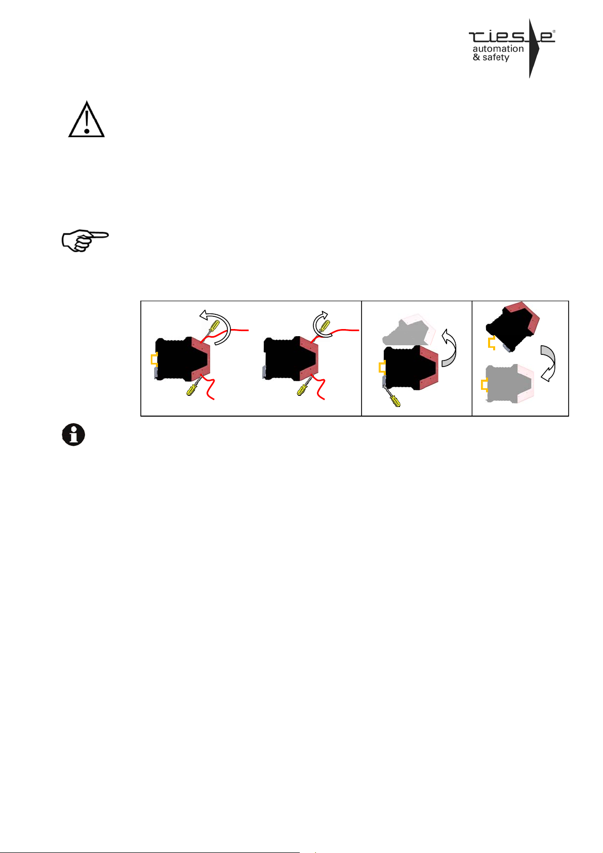
Zum Austausch des Gerätes empfehlen
wir jedes Kabel einzeln abzuschrauben
und sofort an das Austauschgerät anzuschrauben.
(1) Kabel abschrauben und an das Aus-
tauschgerät anschrauben
(2) Nehmen Sie das defekte Gerät von
der Normschiene
(3) Montieren Sie das neue Gerät auf die
Normschiene.
1 2 3
Anzeigen, Fehler, Störungen
und Auswirkung
Spannungsversorgung angelegt
Eingang S12 aktiv
Eingang S22 aktiv
Sicherheitsausgänge aktiv
Gleichzeitigkeit verletzt
Versorgungsspannung nicht korrekt
Verdrahtungsfehler
Sicherheitsrelevanter Verdrahtungsfehler
Kein Rücklesekontakt
Querschluß S11 – S21
Interner Fehler. Gerät muss eingeschickt
werden.
Maintenance and repair
The SAFE FLEX works maintenance
free.
Do not execute maintenance operations on an energized device!
For exchange of the device, we suggest
to screw off every cable individually and
screw them on to the exchange device
immediately.
(1) Screw off the cables and screw them
on to the exchange device
(2) Remove the defective device from
the DIN rail
(3) Mount the new device on the DIN
rail.
Indicators, errors, faults and
effects
Power supply connected
Input S12 active
Input S22 active
Safety outputs active
Simultaneity violation
Power supply failure
Wiring error
Security-relevant wiring error
Feedback contact error
Cross circuits S11 – S21
Internal error. Please send back the de-
vice to riese electronic.
070311 6
Page 7

SAFE FLEX
RESET Hinweis
Im Falle einer Fehlermeldung kann das
Gerät aus Sicherheitsgründen nur durch
das Trennen vom Versorgungsnetz neu
gestartet werden (RESET). Es empfiehlt
sich daher in Reihe zum A1 „+“ - Kreis
einen Reset-Schalter zu installieren.
RESET tip
In the case of an error message the device can only be started again with a
separation from the power supply (RESET). Therefore, it is advisable to install
a reset-switch in series to the A1 “+” circuit
070311 7
Page 8

SAFE FLEX
Technische Daten / Technical data
Elektrische Daten
Versorgungsspannung: Supply voltage: 24V DC
Spannungsbereich: Voltage range: 80...125%
Leistungsaufnahme bei UB ohne Last: Power consumption at UB without load: < 3 W
Leistungsaufnahme der Eingangskreise
(pro Eingang):
Max. Belastung der Ausgangskreise
S11, S21 und S31:
Kontaktdaten
Sicherheitsausgänge: Safety outputs: 2
Hilfsausgänge: Auxiliary outputs: 1
Schaltvermögen der Sicherheitsausgänge: Switching capacity at safety outputs: 5 -250V AC/DC
Anzugsverzögerung
Not-Halt, Schutztürwächter,
Zwei-Hand-Relais:
Lichtschranke, Lichtgitter (BWS):
Taktender Sicherheitsschalter:
Ansprechzeit (Rückfallverzögerung)
Not-Halt, Schutztürwächter,
Zwei-Hand-Relais,
Lichtschranke, Lichtgitter (BWS):
Taktender Sicherheitsschalter:
Einschaltverzögerung nach Inbetriebnahme: Switch-on delay at first reset:
Gleichzeitigkeit der Eingangskreise*
Zwei-Hand-Relais,
Lichtschranke, Lichtgitter (BWS) nach:
Minimale Abschaltzeit der Eingänge: Minimum switch off time of the inputs: 50 ms
Kriech- und Luftstrecken (EN 50178)
Verschmutzungsgrad:
Kontaktabsicherung (DIN VDE 0660 Teil 200) contact security (DIN VDE 0660 part 200)
Überspannungskategorie:
Mechanische Daten
Gehäusematerial: Housing material: Polyamid PA 6.6 V0
Abmessungen (B x H x T): Dimension (H x W x D): 22,5 x 100 x 115mm
Gewicht mit Klemmen: Weight with terminals: Max .155g
Lagerung Storage In trockenen Räumen / in dry areas
Umgebungsdaten
Umgebungstemperatur: Operating temperature: -25... +55 °C
Lagertemperatur: Storage temperature: -25... +75 °C
Luftfeuchte (keine Betauung): Humidity (no dewing): < 75%
Schutzart Klemmen: Protection type terminals: IP 20
Schutzart Gehäuse: Protection type housing: IP 20
Stoßfestigkeit (siehe Seite 2):
Leitungsdaten
Leiteranschluss (Litze): Contactor connection (strand): 0,2 mm2-1,5mm²
Anzugsmoment für Anschlussklemmen: Torque setting for connection terminals: 0,5… 0,6 Nm
Max. Leitungslängen (Resetkreis): Max. contactor length (reset circuit): 250 m
Max. Leitungslängen (Eingangskreis): Max. contactor length (input circuit): 250 m
Leiterquerschnitt: Line cross section: 1,5 mm2
Kapazität: Capacity: 150 nF/ km
Widerstand: Resistance: 11,7 Ohm/ km
Electrical details
Power consumption at the input circuits
(each input):
Max. load at output circuits
S11, S21 und S31:
Contact details
Delay on energisation
E-stop, Safety gate,
Two-hand relay:
Light barrier, Light grid (ESPE):
Clocking safety switch:
Response time (Delay on deenergisation)
E-stop, Safety gate,
Two-hand relay,
Light barrier, Light grid (ESPE):
Clocking safety switch:
Simultaneity of input circuits*
Two-hand relay,
Light barrier, Light grid (ESPE) after:
Creeping and Air distance (EN 50178)
Pollution grade:
Over voltage category:
Mechanical details
Environmental details
Shock resistance (see page 2): 10g
Cable cross details
typ. 8mA/ 24V DC
I
≤ 50mA/ 24V DC
MAX
5 mA - 6 A
60 mW – 1500 W (VA)
≤ 68 ms
≤ 60 ms
≤ 40ms
≤ 70 ms
≤ 30 ms
≤ 30 ms
≤ 30 ms
≤ 125ms
≤ 0,5s
S12: ≤ 0,5s
2
3/300V
6,3A flink oder 4A träge
6,3A brisk or 4A inert
Use 60/75°C copper wire only!
Zulassungen Approvals
EN 62061/ EN 13849-1 EN 62061/ EN 13849-1 bis / up to: SIL 3 / PL e / Kat.,Cat. 4
Kat. / Cat. PL MTTFd DC, CCF SIL PFH (1/h) SFF Bemerkung / remarks
4 e
* Synchrone Aktivierung der Eingänge.
100 Jahre /years
hoch / high
hoch / high,
erfüllt / achieved
3 2,15
.10-9
0,9465 "1oo2” System
070311 8
Page 9

SAFE FLEX
Anwendungsbeispiele / Application examples
Kext
Start
S33 S34
S32
S35 S36 A2
A1
+ 24V DC
Kategorie 4, PLe, SIL 3 erreichbar Category 4, PLe, SIL 3 reachable
S22S12S11 S21
Applikation 1
Zwei-kanalige Not-Halt Anwendung mit
überwachtem Start und Querschlusssicherheit.
Das Auslöseelement (Not-Halt-Schalter)
muss an die Eingangskreise (S11/S12
und S21/S22), der Starttaster an
S32/S33 und eine Brücke oder Rückführungskreis an S33/S34 angeschlossen
werden.
0V DC
Die Aktivierung der Ausgänge (13-14,2324, S31) erfolgt nach dem Schließen
und wieder Öffnen des Starttasters bei
geschlossenen Eingangskreisen (NotHalt-Schalter nicht betätigt). Durch Betätigung des Not-Halt-Schalters fallen die
Ausgänge in ihre Grundstellung zurück,
die Kontakte 13-14 und 23-24 sind geöffnet. Der SPS Ausgang S31 ist ausgeschaltet
Allgemeine Informationen:
Für diese Betriebsart müssen die An-
schlussklemmen S35/S36 gebrückt
werden! Die Gleichzeitigkeit* ist bei der
Not-Halt-Anwendung unendlich. Beim
Einschalten der Versorgungsspannung
dürfen beide Eingangskreise keine unterschiedlichen Signale haben. Die NotHalt-Kontakte oder Sicherheitsschalter
müssen entweder beide geschlossen
oder beide offen sein. Das Gerät schaltet bei fehlerhafter Eingangsbeschaltung
in den FAIL-SAFE (Sicherheitsabschaltung).
.
Application 1
Dual-channel e-stop application with
monitoring of the start button and shortcircuit proof.
The e-stop button (trigger element) has
to be connected to the input channels
(S11/S12 and S21/S22) and the start
button to the reset circuit (S32/S33). Link
S33 to S34 with a bridge or the feedback
control loop.
The activation of the outputs (13-14,2324,S31) results after closing and reopening the start button, both input
channels have to be closed (e-stopbutton not pressed). If the e-stop is
pressed, the outputs of the device fall off
into the initial state immediately, the
contacts 13-14 and 23-24 are opened.
The auxiliary output S31 becomes i nactive.
General information:
For this operating mode, the terminals
S35/S36 must be bridged. For the e-stop
mode, the simultaneity* of the channels
is infinite. The two channels must not
have different signals when the supplyvoltage is switched on. That means: The
contacts of the e-stop button or safety
switch have to be both opened or both
closed. In case of a faulty input-wiring,
the device will switch to the FAIL-SAFE
mode (safety switch-off).
* Eine synchrone Aktivierung der Eingänge ist nicht nötig, aber ein erneuter Start ist nach Anforderung der Sicherheitsfunktion (Abschalten) nur dann möglich, wenn beide Sicherheitseingänge über einen Zeitraum von mindestens
50 ms zusammen deaktiviert waren.
* A synchronic activation of the inputs is not necessary, but a restart after executionof the safety function (switching
off) is only possible if both safety inputs had been deactivated at the same time for a period of at least 50 ms.
070311 9
Page 10

SAFE FLEX
Kext
Start
S33 S22S12S11 S21S34
S32
S35 S36 A2
A1
+24V DC
0V DC
Applikation 2
Zwei-kanalige Schutztür-Anwendung
mit überwachtem Start und Querschlusssicherheit.
Die Auslöseelemente (Schutztürschalter)
müssen an die Eingangskreise (S11/
S12 und S21/ S22) und der Starttaster
an den Rückführkreis (S32/ S33). Eine
Brücke oder ein Rückführungskreis
muss an S33/ S34 angeschlossen werden. Die Aktivierung der Ausgänge (1314, 23-24, S31) erfolgt nach dem
Schließen und Wiederöffnen des Starttasters bei geschlossenen Eingangskreisen (Schutztürschalter ist nicht betätigt).
Durch Öffnen eines oder beider Kontakte des Schutztürschalters (durch Öffnen
der Schutztür) fallen die Ausgänge in
ihre Grundstellung zurück, die Kontakte
13-14 und 23-24 sind geöffnet, der
Hilfsausgang S31 ist ausgeschaltet. Ein
neuer Zyklus kann erst nach Öffnen
beider Schutztürtaster erfolgen.
Allgemeine Informationen:
Für diese Betriebsart müssen die Anschlussklemmen S35/S36 gebrückt
werden! Die Gleichzeitigkeit* ist bei der
Schutztür-Anwendung unendlich. Beim
Einschalten der Versorgungsspannung
dürfen beide Eingangskreise keine unterschiedlichen Signale haben. Die
Schutztür-Kontakte müssen entweder
beide geschlossen oder beide offen
sein. Das Gerät schaltet bei fehlerhafter
Eingangsbeschaltung in den FAIL-SAFE
(Sicherheitsabschaltung).
Kategorie 4, PLe, SIL 3 erreichbar Category: 4 , PL e, SIL 3 reachable
* Synchrone Aktivierung der Eingänge ist nicht nötig aber erneuter Start nach Anforderung der Sicherheitsfunktion
ist nur dann möglich wenn beide Sicherheitseingänge über einen Zeitraum von zumindest 50 ms zusammen deaktiviert waren.
* A synchronic activation of the inputs is not necessary, but a restart after executionof the safety function (switching
off) is only possible if both safety inputs had been deactivated at the same time for a period of at least 50 ms.
Application 2
Dual-channel safety gate application
with monitored start and short-circuit
proof.
The safety gate switches need to be
connected to the input circuits (S11/ S12
and S21/ S22) and the start button to the
feedback control loop (S32/ S33). A
bridge or a feedback control loop needs
to be connected to S33/ S34. The activation of the outputs (13-14, 23-24, S31)
results from closing and reopening of the
start button at the state of closed input
channels. (Safety gate button is not
pressed.)
If one or both safety gate switches are
opened (by opening the safety gate) the
outputs of the device fall off immediately,
the contacts 13-14 and 23-24 are
opened. The auxiliary output S31 becomes inactive. A reset can not be effected until both safety gate switches are
opened.
General information:
For this operation mode, the terminals
S35/S36 must be bridged! For the safety
gate function the simultaneity* of the
channels is infinite. The two channels
must not have different signals when the
supply-voltage is switched on. That
means: the contacts of the safety gate
switch have to be both opened or both
closed.
In case of a faulty input-wiring, the device will switch to the FAIL-SAFE mode
(safety switch-off).
070311 10
Page 11

SAFE FLEX
Kext
S33 S22S12S11 S21S34
S32
S35 S36 A2
A1
+24V DC
0V DC
Applikation 3
Zwei-kanalige Schutztür-Anwendung
mit automatischem Start und Querschlusssicherheit.
Die Auslöseelemente (Schutztürschalter)
müssen an die Eingangskreise (S11/S12
und S21/S22) angeschlossen werden.
Eine Brücke oder Rückführungskreis an
S32/S33 konfiguriert das Gerät für den
automatischen Start. Die Aktivierung der
Ausgänge 13-14, 23-24 und S31 erfolgt
nach dem Schließen der Schutztürtaster.
Durch Öffnen eines oder beider Kontakte des Schutztürschalters fallen die
Ausgänge sofort in ihre Grundstellung
zurück, die Kontakte 13-14 und 23-24
sind geöffnet, der Hilfsausgang S31 ist
ausgeschaltet.
Ein neuer Zyklus kann erst nach Öffnen
beider Schutztürkontakte erfolgen.
Allgemeine Informationen:
Für diese Betriebsart müssen die Anschlussklemmen S35/S36 gebrückt
werden! Die Gleichzeitigkeit* ist bei der
Schutztür-Anwendung unendlich. Beim
Einschalten der Versorgungsspannung
dürfen beide Eingangskreise keine unterschiedlichen Signale haben. Die
Schutztür-Kontakte müssen entweder
beide geschlossen oder beide offen
sein. Das Gerät geht bei fehlerhafter
Eingangsbeschaltung in den FAIL-SAFE
(Sicherheitsabschaltung).
Kategorie 4, PLe, SIL 3 erreichbar Category 4, PLe, SIL 3 reachable
* Eine synchrone Aktivierung der Eingänge ist nicht nötig. Ein erneuter Start ist, nach Anforderung der Sicherheitsfunktion, nur dann möglich wenn beide Sicherheitseingänge über einen Zeit raum von mindestens 50 ms zusammen deaktiviert waren.
* A synchronic activation of the inputs is not necessary, but a restart after executionof the safety function
(switching off) is only possible if both safety inputs had been deactivated at the same time for a period of at least
50 ms.
Application 3
Dual-channel safety gate application
with automatic start and short-circuit
proof.
The safety gate switch has to be connected to the input circuits (S11/S12 and
S21/S22). A bridge or feedback control
loop (S32/S33) switches the device into
the automatic start mode. The activation
of the outputs 13-14, 23-24 and S31
results from closing the contacts of the
safety gate switch. By opening one or
both contacts of the safety gate switch
the outputs of the device fall off into the
initial state immediately, the contacts 1314 and 23-24 are opened. The auxiliary
output S31 becomes inactive.
A reset can not be effected until both
safety gate switches are opened simultaneously.
General information:
For this operation mode the terminals
S35/S36 must be bridged. For the safety
gate function the simultaneity* of the
channels is infinite. The two channels
must not have different signals when the
supply-voltage is switched on. That
means: The contacts of the safety gate
switch have to be both opened or both
closed.
In case of a faulty input-wiring, the device will switch to the FAIL-SAFE mode
(safety switch-off).
070311 11
Page 12

SAFE FLEX
S1
Kext
S12
S33
S11
S34
S32
S35 S36 A2
A1
+24V DC
S21
0V DC
Applikation 4
Zwei-Hand-Applikation
Werden die Taster S1 und S2 gleichzei-
S2
S22
tig gedrückt gehalten, so werden die
Ausgänge 13-14, 23-24 geschlossen
und der SPS-Ausgang S31 eingeschaltet.
Wird einer oder beide Taster losgelas-
S36
sen, so öffnen sich die Ausgänge 13-14
und 23-24 sofort. S31 wird ausgeschalten. Nur nach Loslassen beider Taster
kann ein neuer Zyklus gestartet werden.
Bei nicht synchroner Betätigung (t>0,5s)
werden die Ausgänge nicht freigegeben.
Die Ausgänge 13-14 und 23-24 bleibe n
geöffnet, S31 bleibt ausgeschaltet.
Allgemeine Informationen:
Für diese Betriebsart müssen die Anschlussklemmen S35/S36 gebrückt
werden! Die Zeit zwischen der Betätigung der Taster S1 und S2 ist auf max.
0,5s begrenzt. Bei Überschreitung dieser
Zeit, kann nur nach Öffnen beider Taster
wieder ein neuer Zyklus gestartet werden. Die LEDs IN1 und IN2 blinken in
diesem Fall solange bis die Taster S1
und S2 innerhalb von 0,5s betätigt werden. Beim Einschalten der Versorgungsspannung dürfen die Zwei-Hand-Taster
nicht gedrückt sein. Das Gerät geht bei
fehlerhafter Eingangsbeschaltung in den
FAIL-SAFE (Sicherheitsabschaltung).
Application 4
Two-hand application
If the push buttons S1 and S2 are being
pressed simultaneously, the outputs 1314, 23-24 are closed and output S31 is
turned on.
After releasing one or both push buttons
the outputs 13-14 and 23-24 open immediately and the output S31 turns off.
Only after releasing both push buttons a
new cycle can be started.
By asynchronous actuation (t>0,5s) the
outputs will not be released. The outputs 13-14 and 23-24 remain opened,
output S31 remains turned off.
General information:
For this operation mode the terminals
S35/S36 must be bridged. The time
between pressing both switches is limited to max. 0,5s. After exceeding this
period, a new cycle can only be started
after releasing both push buttons. In this
case, the LEDs IN1 and IN2 will blink
until both buttons (S1 and S2) will be
pressed within 0,5s. In the moment of
turning on the supply voltage, the push
buttons must not be actuated.
In case of a faulty input-wiring, the device will switch to the FAIL-SAFE mode
(safety switch-off).
Für Type 3c, Ple, SIL 3 erreichbar For type 3c, Ple, SIL 3 reachable
070311 12
Page 13

SAFE FLEX
BWS / ESPE
L+
S21S34
A2
OSSD1
S12
0V DC
Kext
S33
S32
S11
S35
A1
+24V DC
OSSD2
S22
S36
Applikation 5
Zwei-kanalige Anwendung zum Anschluss von OSSD-Kontakten (PNP)
L-
einer BWS mit automatischem Start und
Versorgung der BWS über das SAFE
FLEX.
Die Auslöselemente OSSD1 und
OSSD2 müssen an die SicherheitsEingangskreise (S12, S22) angeschlossen werden. Die Brücke (oder der Rücklesekreis) S32-S33 konfiguriert das
Gerät für den automatischen Start. Die
Aktivierung der Ausgänge erfolgt nach
der Aktivierung der Ausgänge der BWS
(OSSDs haben High-Signal). Wird der
Lichtweg unterbrochen, schalten die
OSSDs der BWS ab (Low-Signal) und
die Ausgänge des SAFE FLEX fallen in
ihre Grundstellung zurück. Die Kontakte
13-14 und 23-24 sind geöffnet, der
Hilfsausgang S31 ist ausgeschalten.
Die Versorgung der Lichtschranke / des
Lichtgitter erfolgt über das SAFE FLEX
(Minus-Leitung an S36, Plus-Leitung an
S21, I
max
Allgemeine Informationen:
Für diese Betriebsart dürfen die Anschlussklemmen S35/S36 NICHT
gebrückt sein! Die Gleichzeitigkeit wird
durch die Reihenfolge der High-Signale
an den Eingangsklemmen S12 und S22
bestimmt. Das High-Signal am Eingang
S22 darf maximal 0,5s nach dem HighSignal am Eingang S12 anliegen. Ein
High-Signal am Eingang S12 kann beliebig nach dem High-Signal am Eingang
S22 angelegt werden. Bei Überschreitung der Gleichzeitigkeit kann nur nach
Deaktivierung beider OSSDs wieder ein
neuer Zyklus gestartet werden. Die
Sicherheitseingänge S12/S22 werden
nur dann ausgewertet, wenn sie erst
nach dem Einschalten der Versorgungsspannung aktiviert (High-Signal) wurden.
Ansonsten müssen die Eingänge S12
und S22 kurz deaktiviert und anschließend aktiviert werden.
Application 5
Dual channel application for connecting
OSSD contacts (pnp) of an ESPE with
automatic start and supply of the ESPE
by the SAFE FLEX.
OSSD1 and OSSD2 have to be connected to the input circuits (S11/S12 and
S21/S22). The bridge (or the feedback
control loop) S32/S33 switches the device into the automatic start mode. The
activation of the outputs results from the
activation of the outputs of the ESPE
(OSSDs outputs have high-signal). If the
optical way of the light barrier is interrupted the OSSD outputs of the ESPE
turn off (low signal) and the safety outputs of the SAFE FLEX fall off into the
initial state. The contacts 13-14 and 2324 are opened. The auxiliary output S31
is inactive.
The power supply of the light barrier/
light curtain is provided by the SAFE
= 50mA)
FLEX (negative pole to S36, positive
pole to S21, I
General information:
For this operation mode, the terminals
S35/S36 must NOT be bridged! The
simultaneity is defined by the order of
the high signals at the inputs S12 and
S22. The high-signal at the input S22
may be activated maximally 0,5s after
the high-signal at the input S12. A Highsignal at the entrance S12 can be activated as desired after the High-signal at
S22. After exceeding the simultaneity, a
new cycle can only be started after deactivating both OSSDs. The safety inputs S12/S22 are only monitored when
they were activated after turning on the
power supply.
The safety inputs are only checked if
they had not been activated until the
power supply had been switched on
(high signal). Otherwise, the inputs S12
and S22 must be deactivated for a short
= 50mA)
max
term and reactivated afterwards.
Kategorie 4, PLe, SIL 3 erreichbar Category 4, PLe, SIL 3 reachable
070311 13
Page 14

SAFE FLEX
BWS / ESPE
L+
S21S34
L+
A2
S21
A2
OSSD1
0V DC
OSSD1
S12
0V DC
BWS / ESPE
OSSD2
S12
Kext
Start
S33 S34
S32
S11
S35
A1
+24V DC
Kext
+24V DCx
S33
S32
S11
S35
A1
+24V DC
S22
OSSD2
S22
S36
Application 6
Dual channel application for connecting
OSSD contacts (pnp) of an ESPE with
monitored start and supply of the ESPE
by the SAFE FLEX.
OSSD1 and OSSD2 have to be connected to the input circuits (S11/S12 and
S21/S22). Connect the start button to
S32-S33 and a bridge or a feedback
control loop to S33-S34. The activation
of the outputs results from closing and
re-opening of the start button while the
outputs of the ESPE are activated
(OSSDs emit high-signal).
When the optical path of the light barrier
is interrupted, the OSSD outputs of the
ESPE turn off (low signal) and the safety
outputs of the SAFE FLEX fall off to the
initial state. The contacts 13-14 and 2324 are opened, the auxiliary output S31
is turned off.
The power supply of the light barrier/
light curtain is provided by the SAFE
FLEX (positive pole to S21, negative
pole to S36, I
max
General information:
For this operation mode, the terminals
S35/S36 must NOT be bridged. The
simultaneity is defined by the order of he
high signals at the inputs S12 and S22.
The high-signal at the input S22 may be
activated maximally 0,5s after the highsignal at the input S12. A high-signal at
the input S12 can be activated as desired after the high-signal at S22. After
exceeding the simultaneity a new cycle
can only be started after deactivating the
OSSDs. The safety inputs S12/S22 are
only checked if they hadn’t been startet
before the power supply had been activated.
= 50mA)
S36
Applikation 6
Zwei-kanalige Anwendung zum Anschluss von OSSD-Kontakten (PNP)
L-
einer BWS mit überwachtem Start und
Versorgung der BWS über das SAFE
FLEX.
Die Auslöselemente OSSD1 und
OSSD2 müssen an die SicherheitsEingangskreise (S12, S22), der StartTaster an S32-S33 und eine Brücke
oder ein Rücklesekreis an S33-S34
angeschlossen werden. Die Aktivierung
der Ausgänge erfolgt nach dem Schließen und wieder Öffnen der Starttaste bei
aktiven Ausgängen der BWS (OSSD´s
haben High-Signal).
Wird der Lichtweg unterbrochen, schalten die OSSDs der BWS ab und die
Ausgänge des SAFE FLEX fallen in ihre
Grundstellung zurück. Die Kontakte 1314 und 23-24 sind geöffnet, der Hilfsausgang S31 ist ausgeschaltet.
Die Versorgung der Lichtschranke / des
Lichtgitter erfolgt über das Gerät SAFE
FLEX (Minus-Leitung an S36 und PlusLeitung an S21) und ist auf 50 mA beschränkt.
Allgemeine Informationen:
Für diese Betriebsart dürfen die Anschlussklemmen S35/S36 NICHT
gebrückt sein! Die Gleichzeitigkeit wird
durch die Reihenfolge der High-Signale
an den Eingangsklemmen S12 und S22
bestimmt. Das High-Signal am Eingang
S22 darf maximal 0,5s nach dem HighSignal am Eingang S12 aktiviert werden.
Ein High-Signal am Eingang S12 kann
beliebig nach dem High-Signal am Eingang S22 angelegt werden. Bei Überschreitung der Gleichzeitigkeit kann nur
nach Deaktivierung beider OSSDs wieder ein neuer Zyklus gestartet werden.
Die Sicherheitseingänge S12/S22 werden nur dann ausgewertet, wenn sie erst
nach dem Einschalten der Versorgungsspannung aktiviert (High-Signal) wurden
Kategorie 4, PLe, SIL 3 erreichbar Category 4, PLe, SIL 3 reachable
Applikation 7
L-
0V DC
Zwei-kanalige Anwendung zum An-
schluss von OSSD-Kontakten (PNP)
einer BWS mit automatischem Start und
externer Versorgung der BWS.
Die Lichtschranke / das Lichtgitter wird
extern versorgt. Die Minus-Leitung der
Lichtschranke/Lichtgitter wird zusätzlich
an S36 angeschlossen.
Sonstige Funktion siehe Applikation 5.
Application 7
Dual channel application for connecting
OSSD contacts (pnp) of an ESPE with
automatic start and supply of the ESPE
by an external power supply.
The light barrier / light curtain is supplied
by an external power supply. The negative pole of the light barrier / light curtain
is connected additionally to terminal
S36.
Other functions same as in application 5.
Kategorie 4, PLe, SIL 3 erreichbar Category 4, PLe, SIL 3 reachable
070311 14
Page 15

SAFE FLEX
BWS / ESPE
Kext
Start
S33 S34
S32
S11
S35
A1
+24V DC
START
+24VDC
Kext
S33
S32 S11S22
A1
S35
Kext
S33
S32 S11S22
A1
S35
+24VDC
L+
+24V DCx
S21
A2
S34
S36 S12
S34
S36 S12
OSSD1
S12
0V DC
BWS
ESPE
PNP TEST
BWS
ESPE
L+
GND
PNP TEST
0VDC
OSSD2
GND
S22
L+
A2
0VDC
+24VDCx
S21
A2
L-
0V DC
S36
+24VDCx
S21
Applikation 8
Zwei-kanalige Anwendung zum Anschluss von OSSD-Kontakten (PNP)
einer BWS mit überwachtem Start und
externer Versorgung der BWS.
Die Lichtschranke / das Lichtgitter wird
extern versorgt. Die Minus-Leitung der
Lichtschranke/Lichtgitter wird zusätzlich
an S36 angeschlossen.
Sonstige Funktion siehe Applikation 6.
Application 8
Dual channel application for connecting
OSSD contacts (pnp) of an ESPE with
monitored start and supply of the ESPE
by an external power supply.
The light barrier / light curtain is supplied
by an external power supply. The negative pole of the light barrier / light curtain
is connected additionally to terminal
S36.
Other functions same as in application 6.
Kategorie: 4, PL e, SIL 3 erreichbar Category 4, PLe, SIL 3 reachable
Applikation 9
Ein-kanalige Überwachung einer BWS
Typ 2 bzw. eines Sicherheitssensors mit
einem PNP-Ausgang (OSSD) und zyklischer Testung, mit überwachtem Start
und externer Versorgung der BWS/ des
Sicherheitssensors
Der Testeingang des Auslöseelementes
muss an den taktenden Ausgangskreis
S11 des SAFE FLEX und der OSSD des
Auslöseelementes an den Eingangskreis
S22 angeschlossen werden. Die Klemme S12 darf nicht beschalten werden.
Der Start-Taster wird an den Startkreis
(S32/S33) angeschlossen. Die Klemmen
S33-S34 müssen in diesem Moment
über die Brücke oder den Rücklesekontakt geschlossen sein. Die Aktivierung
der Sicherheitsausgänge des SAFE
FLEX erfolgt, bei aktiviertem OSSD,
nach dem Schließen und Wiederöffnen
des Startkreises (Starttaste).
Application 9
One channel application for monitoring
an ESPE (type 2) or safet y sensor with
pnp-output (OSSD) and cycling test, with
monitored start and supply of the ESPE
by an external power supply.
Connect the test input of the ESPE to
the clocked output S11 of the SAFE
FLEX and the OSSD of the ESPE to the
input S22. The terminal S12 must not be
used.
The start button is connected to
S32/S33. In this moment, S33 has to be
linked to S34 by a bridge or a feedback
control loop. The activation of the safety
outputs of the SAFE FLEX results from
closing and reopening the start circuit
while the OSSD is activated.
Kategorie: 2, PLd, SIL 2 erreichbar Category: 2, PLd, SIL 2 reachable
Applikation 10
Ein-kanalige Überwachung einer BWS
Typ 2 bzw. eines Sicherheitssensors mit
einem PNP-Ausgang (OSSD) und zyklischer Testung, mit automatischem Start
und externer Versorgung der BWS/ des
Sicherheitssensors. (24V DC)
Der Testeingang des Auslöseelementes
muss an den taktenden Ausgangskreis
S11 des SAFE FLEX und der OSSD des
Auslöseelementes an den Eingangskreis
S22 angeschlossen werden. Die Klemme S12 darf nicht beschalten werden.
Eine Brücke oder Rückführungskreis an
S32/S33 konfiguriert das Gerät für den
automatischen Start. Die Aktivierung der
Sicherheitsausgänge des SAFE FLEX
erfolgt nach der Aktivierung des PNPAusganges des Auslöseelemtentes.
Application 10
One channel application for monitoring
an ESPE (type 2) or safety sensor with
pnp-output (OSSD) and periodic test,
with automatic start and supply of the
ESPE by an external power supply.
(24V DC)
Connect the test input of the ESPE to
the clocked output S11 of the SAFE
FLEX and the OSSD of the ESPE to the
input S22. The terminal S12 must not be
used.
The bridge or feedback control loop S32S33 enables the automatic start mode.
The activation of the safety outputs of
the SAFE FLEX occurs after the activation of the OSSD of the ESPE.
Kategorie: 2, PLd, SIL 2 erreichbar Category: 2, PLd, SIL 2 reachable
070311 15
Page 16

SAFE FLEX
BWS
ESPE
START
S33
S32 S11S22
A1
S35
+24VDC
Kext
S33
S32 S11S22
A1
S35
+24VDC
Kext
S33
S32
S35
A1
+24V DC
Kext
S34
S12
S34
S12
S12
PNP TEST
BWS
ESPE
L+
GND
PNP TEST
TE
L+
S11
S21S34
A2
0V DC
GND
L+
S36
A2
0VDC
S36
A2
0VDC
A
S22
S21
S36
S21
L-
Applikation 11
Ein-kanalige Überwachung einer BWS
Typ 2 bzw. eines Sicherheitssensors mit
einem PNP-Ausgang (OSSD) und zyklischer Testung, mit überwachtem Start
und Versorgung der BWS / des Sicherheitssensors über das SAFE FLEX .
Die Versorgung der Lichtschranke / des
Lichtgitters erfolgt über das Gerät SAFE
FLEX (Minus-Leitung an S36 und PlusLeitung an S21) und ist bis 50 mA beschränkt.
Sonstige Funktion siehe Applikation 9.
Application 11
One channel application for monitoring
an ESPE (type 2) or safet y sensor with
pnp-output (OSSD) and periodic test and
monitored start and supply of the ESPE
by the SAFE FLEX.
The power supply of the light barrier/
light curtain is provided by the SAFE
FLEX (positive pole to S21, negative
pole to S36, I
max
Other functions same as in application 9.
= 50mA).
Kategorie: 2, PLd, SIL 2 erreichbar Category: 2, PLd, SIL 2 reachable
Applikation 12
Ein-kanalige Überwachung einer BWS
Typ 2 bzw. eines Sicherheitssensors mit
einem PNP-Ausgang (OSSD) und zyklischer Testung, mit automatischem Start
und Versorgung der BWS / des Sicherheitssensors über das SAFE FLEX
Die Versorgung der Lichtschranke / des
Lichtgitter erfolgt über das Gerät SAFE
FLEX (Minus-Leitung an S36 und PlusLeitung an S21) und ist bis 50 mA beschränkt.
Sonstige Funktion siehe Applikation 10.
Application 12
One channel application for monitoring
an ESPE (type 2) or safety sensor with
pnp-output (OSSD) and periodic test,
with automatic start and supply of the
ESPE by the SAFE FLEX
The power supply of the light barrier/
light curtain is provided by the SAFE
FLEX (positive pole to S21, negative
pole to S36, I
max
= 50mA).
Other functions same as in
application 10.
Kategorie: 2, PLd, SIL 2 erreichbar category: 2, PLd, SIL 2 reachable
Applikation 13
Überwachung eines taktenden Sicherheitsschalters mit automatischem Start
und Versorgung des taktenden Sicherheitsschalters über das SAFE FLEX
Allgemeine Informationen:
Für diese Betriebsart dürfen die Anschlussklemmen S35/S36 NICHT
gebrückt sein! Die Brücke (oder Rücklesekreis) S32-S33 konfiguriert das Gerät
für den automatischen Start.
Beim Einschalten der Versorgungsspannung darf am Ausgang des taktenden
Sicherheitsschalters kein Signal anliegen. Solange am Takteingang kein Eingangssignal erkannt wird, bleibt das
Application 13
Monitoring of a clocking safety switch
with automatic start and supply of the
clocking safety switch by the SAFE
FLEX
General information:
For this operation mode the terminals
S35/S36 must not be bridged. A bridge
or feedback control loop (S32/S33)
switches the device into the automatic
start mode.
While turning on the power supply there
must not be a signal at the output of the
clocked safety switch. As long as no
signal is detected at the clock input the
device remains in a wait state.
Gerät im Wartezustand.
Kategorie: 4, PL e, SIL 3 erreichbar Category 4, PLe, SIL 3 reachable
070311 16
Page 17

SAFE FLEX
TE
S12
S12
S12
13
14
L+
S21
A2
L+
+24V DCx
S21S34
A2
0V DC
L+
+24V DCx
S21
A2
0V DC
23
U1
SAFE X4.1
K1
24
S11
0V DC
TE
S11
TE
S11
Y1 Y2
K21
U22
+24V DC
Start
S32
A1
+24V DC
Kext
S32
A1
+24V DC
Start
S32
A1
+24V DC
Start
S33 S34
S32
SAFE FLEX
A1
+24V DC
+ Eingangsbeschaltung
+ inputs wiring
Kext
S33 S34
S35
S33
S35
Kext
S33 S34
S35
A2
0V DC
A
S22
S22
A1
A2
0V DC
Application 14
Monitoring of a clocking safety switch
with monitored start and supply of the
clocked safety switch by the SAFE FLEX
The SAFE FLEX provides a clock at
terminal S11.
The power supply of the clocked switch
is provided by the SAFE FLEX (positive
pole to S21, negative pole to S36, I
50mA)
General information:
For this operation mode the terminals
S35/S36 must not be bridged.
While turning on the power supply, there
must not be a signal at the output of the
clocking safety switch. As long as no
signal is detected at the clock input the
device remains in a wait state.
max
=
S22
Applikation 14
Überwachung eines taktenden Sicher-
L-
A
S36
heitsschalters mit überwachtem Start
und Versorgung des taktenden Sicherheitsschalters über das SAFE FLEX
Über das SAFE FLEX (S11) wird ein
Takt an Eingang (TE) des taktenden
Sicherheitsschalters angelegt.
Die Versorgung des Sicherheitsschalters
erfolgt über das SAFE FLEX (MinusLeitung an S36 und Plus-Leitung an
S21, I
= 50mA)
max
Allgemeine Informationen:
Für diese Betriebsart dürfen die Anschlussklemmen S35/S36 NICHT
gebrückt sein! Beim Einschalten der
Versorgungsspannung darf am Ausgang
des taktenden Sicherheitschalters kein
Signal anliegen. Solange am Takteingang kein Eingangssignal erkannt wird,
bleibt das Gerät im Wartezustand.
Kategorie 4, P e, SIL 3 erreichbar Category 4, PLe, SIL 3 reachable
Application 15
Monitoring of a clocking safety switch
with automatic start and supply of the
clocking safety switch by an external
power supply
The clocking safety switch is supplied by
an external power supply. The negative
pole of the clocking safety switch is to be
connected additionally to terminal S36.
S36
Applikation 15
Überwachung eines taktenden Sicher-
L-
0V DC
heitsschalters mit automatischem Start
und externer Versorgung des taktenden
Sicherheitsschalters
Der taktende Sicherheitsschalter wird
extern versorgt. Die Minus-Leitung des
Sicherheitsschalters wird zusätzlich an
S36 angeschlossen.
Sonstige Funktion siehe Applikation 9.
Other functions same as in application 9.
Kategorie 4, PLe, SIL 3 erreichbar Category 4, PLe, SIL 3 reachable
Applikation 16
Überwachung eines taktenden Sicher-
L-
A
0V DC
S36
heitsschalters mit überwachtem Start
und externer Versorgung des taktenden
Sicherheitsschalters
Der taktende Sicherheitsschalter wird
extern versorgt. Die Minus-Leitung des
Sicherheitsschalters wird zusätzlich an
S36 angeschlossen.
Sonstige Funktion siehe Applikation 10.
Application 16
Monitoring of a clocking safety switch
with monitored start and supply of the
clocking safety switch by an external
power supply
The clocking safety switch is supplied by
an external power supply. The negative
pole of the clocked safety switch is to be
connected additionally to terminal S36.
Other functions same as in
application 10.
Kategorie 4, PLe, SIL 3 erreichbar Category 4, PLe, SIL 3 reachable
Applikation 17
Kontakterweiterung mit SAFE X4.1 bei
Applikationen mit überwachtem Start
Zur Überwachung werden die ÖffnerKontakte der Erweiterung in den Rückle-
23
13
14
24
sekreis S33-S34 des SAFE FLEX ein-
43
33
gebunden.
Bei geschützter Verlegung der Leitun-
34
44
gen und Ausschluss der Spannungsverschleppung zwischen U1 und K1/K21 ist
die Erweiterung bis Kategorie 4 geeignet.
Application 17
Contact expansion with SAFE X4.1 in
applications with monitored start
For monitoring, the contacts of the expansion are linked into the feedback
control loop S33/S34 of the SAFE FLEX.
In the case of protected laying of the
wires and exclusion of parasitic voltage
between U1 and K1/K21, the expansion
is qualified up to safety category 4.
Kategorie: bis 4, PL e, SIL 3 erreichbar category: up to 4, PL e, SIL 3 reachable
070311 17
Page 18

SAFE FLEX
23
13
S32
SAFE FLEX
A1
S33 S34
A2
14
U22
Y1 Y2
U1
SAFE X4
K21
A1
K1
24
Applikation 18
Kontakterweiterung mit SAFE X4 bei
Applikationen mit automatischem Start
Zur Überwachung werden die ÖffnerKontakte der Erweiterung in den Rückle-
23
13
A2
14
24
sekreis des SAFE FLEX eingebunden.
43
33
34
44
Application 18
Contact expansion with SAFE X4 in
applications with automatic start
For monitoring the N/C contacts of the
expansion are linked into the feedback
control loop of the SAFE FLEX.
+24V DC
+ Eingangsbeschaltung
+ inputs w irin g
0V DC
+24V DC
0V DC
Kategorie 4, PLe, SIL 3 erreichbar Category 4, PLe, SIL 3 reachable
070311 18
Page 19

Ihr Kontakt zu riese electronic / your contact to riese electronic:
Weitere Länder- / Gebiets – Vertretungen finden Sie auch im Internet:
all our representations can be found on our homepage:
www.automation-safety.de/deutsch/index.htm
www.automation-safety.com/englisch/index.htm
Deutschland
Stammhaus: / Head office
Junghansstr. 16
D-72160 Horb am Neckar
Phone: +49 74 51 / 55 01 0
Fax: +49 74 51 / 55 01 70
info@riese-electronic.de
www.automation-safety.de
www.automation-safety.com
Serviceadresse für ganz Europa /
servic adress for europe
Niederlassung Ost Langenwolschendorf /
Exemplarisch ein Vertreter auf jedem Kontinent
Exemplary one representation on each continent
USA
Norstat Inc.
Rockaway, NJ07866
Phone: +1 97 35 86 25 00
Fax: +1 97 35 86 15 90
Info@norstat.com
www.norstat.com
Stammhaus:
Head office:
Langenwolschendorf branch
Dr.-Riese-Str. 1
D-07937 Langenwolschendorf
Phone: +49 3 66 28 / 72 5 0
Fax: +49 3 66 28 / 72 5 17
Email: info-lawo@automation-sicherheit.de
Taiwan
Daybreak
Taipei Taiwan
Phone: +88 62 88 66 12 31
Fax: +88 62 88 66 12 39
Day111@ms23.hinet.net
Brasilia
Westcon Instrumentacao
04582-000 Sao Paulo-SP
Phone: +55 55 61 74 88
Fax: +55 50 93 25 92
www.wii.com.br
South Africa
CURMECPLANT cc
Bedfordview 2008
Phone: +27 11 87 30 53 69
Fax: +2 71 18 73 05 71
info@curmec.co.za
www.curmec.co.za
control logic
AUS-4006 Queensland, Bowen Hills
Phone: +6 17 32 52 96 11
Fax: +6 17 32 52 87 76
sales@control-logic.com.au
www.control-logic.com.au
Bitte fordern Sie zusätzlich Unterlagen an: /
Please ask for our additional information on:
•Zeitrelais / time-delay relays
•Messrelais / measuring relays
•Sicherheitsrelais / safety relays
•Kundenspezifische Entwicklung und Fertigung elektronischer Baugruppen/
custom-made designs and the fabrication of electronic subassemblies
•Leitfaden für eine partnerschaftliche Elektronikfertigung / (only in German)
Page 20

 Loading...