

Page 1
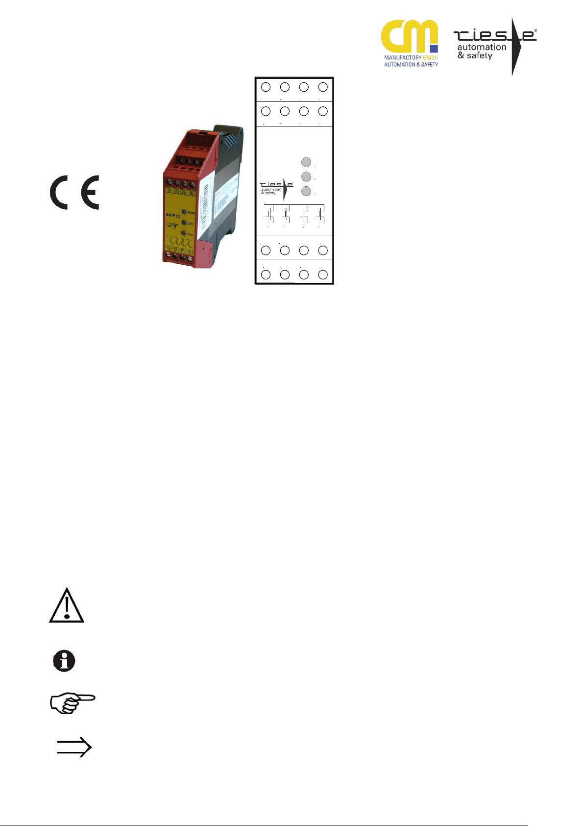
SAFE CL
A1 S36
14 24
PWR
CH1
CH2
SAFE CL
A1
14 24 34 42
A2
34 44
S32
S33 S34
S11
S12 S21 S22
S35
S37
CM Manufactory GmbH
Otto-Hahn-Str. 3
D-72406 Bisingen
Tel. +49-(0)7476-9495-0
Fax. +49-(0)7476-9495-195
www.automation-safety.de
Zielgruppe/
Target audience
Zeichenerklärung/
Explanation of signs
270416 1
SAFE CL
Original Bedienungsanleitung
Sicherheitsschaltgerät für berührungslos wirkende Schutzeinrichtungen
Original operating instruction
Safety controller for safety light curtains and light barriers
Einleitung
Diese Bedienungsanleitung soll Sie mit dem
Sicherheitsnachschaltrelais SAFE CL vertraut machen.
Die Bedienungsanleitung richtet sich an
folgende Personen:
Qualifizierte Fachkräfte, die Sicherheits-
einrichtungen für Maschinen und Anlagen planen und entwickeln und mit den
Vorschriften über Arbeitssicherheit und
Unfallverhütung vertraut sind.
Qualifizierte Fachkräfte, die Sicherheits-
einrichtungen in Maschinen und Anlagen einbauen und in Betrieb nehmen.
In dieser Bedienungsanleitung werden einige Symbole verwendet, um wichtige Informationen hervorzuheben:
Dieses Symbol steht vor Textstellen, die
unbedingt zu beachten sind. Nichtbeachtung
führt zur Verletzung von Personen oder zu
Sachbeschädigung.
Dieses Symbol kennzeichnet Textstellen,
die wichtige Informationen enthalten.
Dieses Zeichen kennzeichnet auszuführende Tätigkeiten.
Nach diesem Zeichen wird beschrieben, wie
sich der Zustand nach einer ausgeführten
Tätigkeit ändert.
© Copyright Alle Rechte vorbehalten. Änderungen,
die dem technischen Fortschritt dienen, vorbehalten.
Introduction
This operating instruction should make
you familiar with the safety relay
SAFE CL.
The operating instruction is addressed to
the following persons:
Skilled personnel who plan or devel-
op safety equipment for machines
and plants and are familiar with the
safety instructions and safety regulations.
Skilled personnel who build in safety
equipment into machines and plants
and start up them.
The operating instruction contains several symbols which are used to high-light
important information:
This symbol shows text passages which
should be noticed. Non-observance leads
to serious injuries or damage of property.
This symbol shows passages which contain important information.
This sign is placed for activities.
After this sign it is described how the
state changes after an explained activity.
© Copyright All rights reserved. Changes,
which serve technical improvements, are reserved.
Page 2
SAFE CL
Bestimmungsgemäße
Verwendung /
Intended application
Zu Ihrer Sicherheit
For your safety
Sicherheitshinweise
Das Sicherheitsnachschaltgerät SAFE CL ist
bestimmt für den Einsatz in:
Berührungslos wirkende Schutz-
einrichtungen (BWS, Lichtschranken,
Lichtgitter und Lichtvorhänge) Typ 4 oder Typ 2
Sicherheitssensor mit 2 PNP-
Ausgängen
Personen- und Sachschutz sind nicht mehr
gewährleistet, wenn das SAFE CL nicht
entsprechend seiner bestimmungsgemäßen
Verwendung eingesetzt wird.
Beachten Sie unbedingt die folgenden
Punkte:
Das SAFE CL darf nur unter Beachtung
dieser Bedienungsanleitung von Fachpersonal installiert und in Betrieb genommen werden, das mit den geltenden
Vorschriften über Arbeitssicherheit und
Unfallverhütung vertraut ist. Elektrische
Arbeiten dürfen nur von Elektrofachkräften durchgeführt werden.
Beachten Sie die jeweils gültigen Vor-
schriften, insbesondere hinsichtlich der
Schutzmaßnahmen.
Reparaturen, insbesondere das Öffnen
des Gehäuses, dürfen nur vom Hersteller oder einer von ihm beauftragten Person vorgenommen werden. Ansonsten
erlischt jegliche Gewährleistung.
Vermeiden Sie mechanische Erschütte-
rungen beim Transport oder im Betrieb;
Stöße größer 10g/0,33Hz können zur
Beschädigung des Gerätes führen.
Montieren Sie das SAFE CL in einem
staub- und feuchtigkeitsgeschützten
Gehäuse (IP54 oder besser); Staub und
Feuchtigkeit können zu Funktionsstörungen führen.
Sorgen Sie für eine ausreichende
Schutzbeschaltung bei kapazitiven und
induktiven Lasten an den Ausgangskontakten.
Der Starttaster ist so anzubringen, dass
man beim Start den Gefahrenbereich
einsehen kann
In regelmäßigen Zeitabständen muss
das SAFE CL ausgelöst werden und auf
richtige Funktion geprüft werden (alle
sechs Monate oder im Wartungszyklus
der Anlage).
Safety indications
The safety control device SAFE CL can
be used for:
Electro sensitive protective equip-
ment (ESPE) type 4 or type 2 (light
curtains and light barriers)
Safety sensor with 2 PNP outputs
Operator and object protection are not
guaranteed, if the SAFE CL will not be
used by the intended application.
Please do pay attention to the following points:
The device must only be built in and
operated by specialized staff, which
is familiar with this instruction and the
current regulations for safety at work
and accident prevention. Working on
electrical equipment is only allowed
for specialized staff.
Pay attention to valid regulations,
particularly in reference to preventative measures.
Any repairs have to be done by the
manufacturer or a person which is
authorized by the manufacturer. It is
prohibited to open the device or implement unauthorized changes, otherwise any warranty expires.
Avoid mechanical vibrations more
than 10g/0,33Hz during the carriage
and during operation.
The SAFE CL must be panel mount-
ed in a housing rated at IP 54 or better, otherwise dampness or dust
could lead to functional impairment.
Adequate fuse protection must be
provided on all output contacts with
capacitive and inductive loads.
The start button must be installed at
a position from where the dangerous
area can be seen and observed.
The safety controller SAFE CL
should be tested in a defined time
period (every six months or after
each check of the plant).
270416 2
Page 3
SAFE CL
A1 A2
Power
Input circuits
S12 S22 S34 S35 S36
Output
circuits
Combination
circuit
S11 S21 S33
MCU1
<Controller 1>
MCU2
<Controller 2>
Safety output circuits
14
24
34
44
S32S37
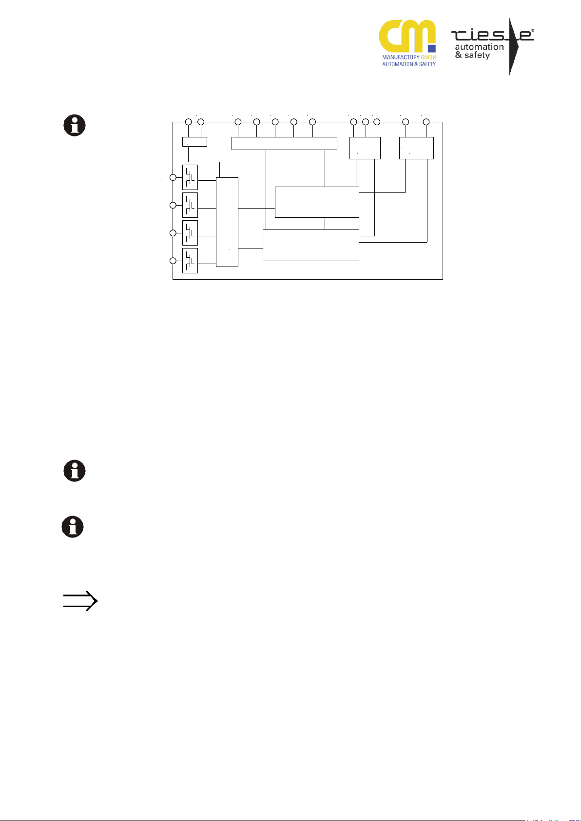
Blockschaltbild
Function diagram
14, 24, 34, 44
S11, S21
S12, S22
S32, S33
S34
S35
S36, S37
Aufbau und Funktionsweise
Sichere Steuerausgänge
Sicherheitseingänge
Verknüpfungskonfiguration
Start-Eingang
Moduswahl (Typ 2 oder Typ 4)
Darf nicht beschaltet werden
Sichere Halbleiterausgänge
Die Start-, Verknüpfungs- und Sicherheitseingangskontakte sind entsprechend des
Verwendungszweckes zu verdrahten (s.
„Montage und Inbetriebnahme“).
Für das Betreiben des Gerätes im Verknüpfungsmodus muss das Gerät für die Art der
Verknüpfung (UND) konfiguriert sein.
Die Ausgangskreise und die Sicherheitsausgänge des Gerätes sind kurzschlussfest.
Sie werden getaktet und von beiden internen Controllern unabhängig überwacht.
Sollte ein Ausgang als Meldeausgang für
eine SPS verwendet werden, sollte der
Softwarefilter der SPS eingeschaltet werden.
Im aktiven Zustand leuchten die LEDs CH1,
CH2, an den Ausgängen liegt das positive
Potential UB an. Im inaktiven Zustand könne die LEDs CH1 und/oder CH2 blinken
(siehe Code-Tabelle) - die Ausgänge haben
das Potential 0V (GND).
Assembly and function
Safety control outputs
Safety inputs
Combination circuit configuration
Start circuit input
Operating mode (type 2 or type 4)
Not to be connected
Safety semiconductor outputs
The start, combination and safety input
contacts have to be wired according to
the intended purpose (see "Mounting and
start-up").
For the operation of the device in combination mode, the device must be configured according to the type of combination
mode (AND).
The output circuits and the safety outputs
of the device are short circuit protected.
The output signals are clocked and independently monitored by both internal
controllers. Is an output used as an auxiliary output for a PLC, the software filter
of the PLC should be enabled.
In the active state of the device CH1 and
CH2 indicators illuminate. The safety
outputs have the positive potential UB
(active HIGH). In the inactive state of
the device CH1 and/or CH2 possibly
flash (see code table) – the safety outputs have ground potential with 0V (logical LOW).
270416 3
Page 4

SAFE CL
Mechanische Montage
Mechanical mounting
Elektrischer Anschluss
Electronic connection
Montage und Inbetriebnahme
Für eine sichere Funktion muss das SAFE
CL in ein staub- und feuchtigkeitsgeschütztes Gehäuse (IP54 oder besser) eingebaut
werden.
Montieren Sie das SAFE CL auf eine
Normschiene
Führen Sie die Verdrahtung entsprechend
des Verwendungszweckes durch. Orientieren Sie sich dabei an den Anwendungs-
beispielen. Generell ist das SAFE CL nach
folgenden Angaben zu verdrahten:
1. Start- und Rückführungskreis
Automatische Aktivierung ohne Überwa-
chung: Brücke zwischen S34 und S21
anschließen.
Überwachter Start: Schließen Sie einen
Starttaster zwischen den Klemmen S34
und S11 an. Dieser Taster darf beim
Einschalten der Versorgungsspannung
nicht betätigt sein.
Überwachen externer Schütze: Schlie-
ßen Sie die Öffnerkontakte der Schütze
in Reihe an die Klemmen des gewählten
Start-Kreises an.
2. Sicherheitseingange
Anschluss BWS Typ 2/4 mit 2 Relais-
ausgängen: Schließen Sie die Schließerkontakte des Auslöseelementes an
S11- S12 und S21-S22 an
Anschluss BWS Typ 2/4 und Sicher-
heitssensor mit jeweils 2 PNPAusgängen: Schließen Sie die positiv
schaltenden Ausgänge des Auslöseelementes an S12 und S22 an.
Anschluss BWS Typ 2 mit zyklischer
Überwachung und einem PNP-Ausgang:
Schließen Sie den Testeingang des
Auslöseelements an S21 und den positiv schaltenden Ausgang an S22 an.
Brücken Sie die Klemmen S11-S35.
3. Verknüpfung konfigurieren
Keine Verknüpfung: Brücken Sie die
Klemmen S32 und S21
UND-Verknüpfung: Klemme S32 bleibt
offen
4. Versorgung anschließen
Schließen Sie die Versorgungsspan-
nung an die Klemmen A1 (+24VDC) und
A2 (GND) an. Die LED PWR leuchtet
Mounting and start-up
The SAFE C must be panel mounted in
an enclosure rated at IP 54 or better,
otherwise dampness or dust could lead
to malfunction.
There is a notch on the rear of the
unit for DIN-Rail attachment.
Assemble the wire appropriate to the
further use. Follow the application ex-
amples. General the SAFE CL has to be
wired under following specifications:
1. Start and feedback control loop
Automatic activation without monitor-
ing of reset circuit: bridge S34 and
S21.
Start circuit monitoring: connect a
start button between S34 and S11.
The start button must not be closed
when switching on the power supply.
Monitoring external contactors: con-
nect the normally closed contacts of
the external contactors in series to
the terminals of the current start circuit.
2. Close the input circuits
Connection of ESPD type2/4 with 2
relay outputs: Please connect the n/o
contacts to S11-S12 and S21-S22
Connection of ESPD and safety sen-
sor type 2/4 with 2 PNP outputs
each. Please connect the positive
switching contacts of the periphery
module to S21-S22.
Connection of ESPD and safety sen-
sor type 2 with one PNP output.
Please connect the testing input of
the periphery module to S21 and the
positive switching contact of the periphery module to S22. Connect a
bridge between S11-S35.
3. Setup combination mode
Operation without any external link-
age: bridge the terminals S32 and
S21
AND-Combination: terminal S32
remains open.
4. Connecting to power supply
Connect the supply voltage to the
terminals A1 (+24VDC) and A2
(GND). LED PWR illuminates
270416 4
Page 5
SAFE CL
1 2 3
Blinkende Anzeigen
Flashing indicators
Die Power LED
leuchtet nicht /
Power LED does
not light
Wartung und Reparatur
Das SAFE CL arbeitet wartungsfrei
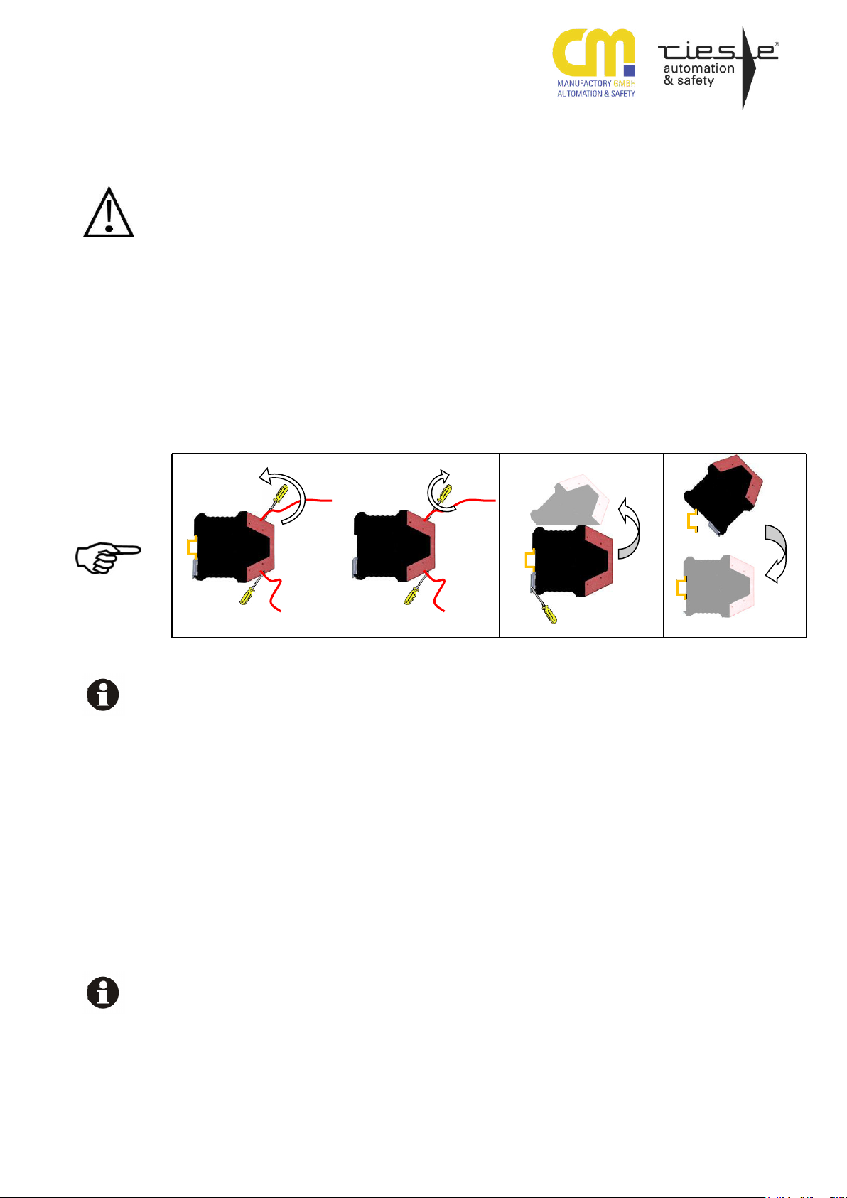
Führen Sie einen Klemmenwechsel nicht
unter Spannung durch!
Zum Austausch des Gerätes empfehlen wir
die Kabel 1 zu 1 abzuschrauben und an das
Austauschgerät anzuschrauben.
(1) Kabel abschrauben und an das Aus-
tauschgerät anschrauben.
(2) Nehmen Sie das defekte Gerät von der
Normschiene
(3) Montieren Sie das neue Gerät auf die
Normschiene
Fehler, Störungen, Auswirkung
und Maßnahmen
Zustandsanzeige / Fehler-Tabelle be-
achten.
Interner Fehler. Gerät muss einge-
schickt werden.
RESET Hinweis
Im Falle einer Fehlermeldung kann das Gerät aus Sicherheitsgründen nur durch das
Trennen vom Versorgungsnetz neu gestartet werden (RESET). Eine Applikationsänderung nach Reset verursacht eine Fehlermeldung. Es empfiehlt sich daher in Reihe zum
A1-Kreis einen Reset-Schalter zu installieren.
Maintenance and repair
SAFE CL works free of maintenance.
Never execute a clamp change on
connected voltage!
For exchange of the device, we advise to
screw off the terminals one-to-one and to
screw on the exchange-device.
(1) Screw off the cables and screw them
on the exchange devise.
(2) Remove the defective device from
the DIN rail
(3) Mount the new device on the DIN rail
Errors, faults, effects and activities
Look at the failure / status indication
table.
Internal error, please send back the
device to CM Manufactory.
RESET tip
In the case of an error message the device can only be restarted after disconnecting from the power supply (RESET).
Change of application after reset will
cause an error message. We recommend
to install a reset switch in line of the A1
circuit.
270416 5
Page 6

SAFE CL
Beschreibung zur Ermittlung des
Blinkcodes
Die LED`s CH1 und CH2 zeigen diverse
Betriebszustände an. Es werden folgende
Zustände angezeigt:
- dauerhaft ein = Alles in Ordnung, Ausgänge sind freigeschaltet
- aus: Eingang nicht aktiv, Ausgänge sind
abgeschaltet
- eine LED blinkt regelmäßig schnell: Ein-
gang aktiv
- beide LEDs blinken regelmäßig:
langsam: wartet auf Startsignal und /
oder Verknüpfungseingang
schnell: wartet auf richtiges zeitgleiches
Abschalten oder
Gleichzeitigkeit verletzt
(nochmalige Betätigung des
Auslöseelements erforderlich).
- beide LEDs blinken wechselweise:
Versorgungsspannung außer halb des Toleranzbereiches
schnell: oberhalb
langsam: unterhalb
- bis zu 12 kurze Blinksignale, dann Pause;
endlos wiederholt: externer Fehler
siehe Tabelle unten
Treten diverse Fehler gleichzeitig auf, können die LEDs unterschiedliche Fehler anzeigen. An der Anzahl der Blinkimpulse
(Blinkcode) zwischen den längeren Pausen, kann abgelesen werden, welcher externe Fehler aufgetreten ist. Gezählt werden immer die Lichtimpulse der Leuchtdioden. Die Anzahl der gezählten Lichtimpulse ergibt den Fehlercode Blinkcode. Mit
Hilfe der Fehlercodetabelle kann die
Fehlerursache lokalisiert und behoben
werden. Blinken die Leuchtdioden unterschiedlich ungleichmäßig dann muss zuerst die erste Leuchtdiode und anschließend die zweite gemäß der Fehlercodetabelle ausgewertet werden.
- bis zu 16 kurze Unterbrechungen des
Leuchtens dann Pause und Wiederholung: Interner Fehler: Reset durchführen
und wenn sich der Fehler wiederholt, Gerät
zur Reparatur einschicken mit Angabe des
Blinkcodes (Die Pausen werden gezählt)
Tipp: Blinken beide LED’s unterschiedlich,
kann der Blinkcode besser abgelesen werden, wenn die andere LED abgedeckt wird.
Description for the determination of the flashing code
The LED `s CH1 and CH2 indicate various operating conditions. The following
conditions are indicated
- permanently illuminated: All outputs
are activated
- permanently off: input deactivated,
outputs are deactivated
- one LED flashes periodically fast:
input is active
- both LEDs flashing periodically:
slowly: waiting for start signal and /
or combination circuit
. fast: waiting for real simultaneous
deactivation or simultaneous ness
(The peripheral switch has
to be activated once more)
- both LEDs flashing alternately =
Supply voltage is out of range
. fast: overvoltage
slowly: undervoltage
- up to 12 short flashing signals, then
break, periodically repeated:
external error, see table below
If various errors occur at the same time,
the LEDs may show different errors. By
the number of flashing impulses between the longer breaks it is possible to
see which external mistakes are pending. Always the light pulses of the LED
are counted. The number of the light
pulses arise the error code. With the
help of the error code table the cause of
fault can be located and rectified. If the
LEDs flash differently, evaluate first the
error code of one LED and then the error code of the other according to the
error code table.
- Up to 16 short interruptions of light-
ened LED, then break, periodically repeated: internal error: Please perform
reset and if the error still appears,
please send in the device for repairing.
Hint: If both LEDs are flashing differently,
the code can be read more easily, when
covering one LED.
270416 6
Page 7
SAFE CL
Code Tabelle
Code
Fehler und mögliche Ursachen
Behebungsmaßnahmen
1
Verbindung der Eingänge S32, S33 ist nicht korrekt
Gerät vom Netz trennen, auf Verdrahtungsfehler
prüfen
2
Kurzschluss an mindestens einem der Ausgänge
14, 24, 34, 44 oder Überlastung
Gerät vom Netz trennen, auf Verdrahtungsfehler
prüfen, ggf. Laststrom prüfen
3
Querschluss oder Fehlfunktion an mindestens
einem der Ausgänge 14, 24, 34, 44
Gerät vom Netz trennen, Verdrahtung prüfen, ggf.
defektes Gerät austauschen
4
Querschluss oder Kurzschluss zu VCC an den
Verbindungen S11, S12, S21 und S22 zum Auslöseelement
Gerät vom Netz trennen, auf Verdrahtungsfehler
prüfen
5
Kurzschluss zu GND an den Verbindungen S11,
S12, S21, S22
Gerät vom Netz trennen, auf Verdrahtungsfehler
prüfen
6
Unzulässige Applikation oder Verdrahtungsfehler
Verdrahtung prüfen, Gerät vom Netz trennen und
wieder einschalten
7
Falsche oder Änderung der Startverdrahtung
S11, S21, S34
Verdrahtung prüfen, Gerät vom Netz trennen und
wieder einschalten
8
Änderung der Verdrahtung an S35 im laufenden
Betrieb S11, S21, S35
Verdrahtung prüfen, Gerät vom Netz trennen und
wieder einschalten
9
Versorgungsspannung außerhalb der Betriebsparameter - Unterspannung
Gerät vom Netz trennen, Betriebsspannung vom
Netzteil überprüfen
10
Versorgungsspannung außerhalb der Betriebsparameter - Überspannung
Gerät vom Netz trennen, Betriebsspannung vom
Netzteil überprüfen
11
Falscher Anschluß , Querschluß, oder Kurzschluß bei BWS mit zyklischer Testung an S21,
S22
oder Über-/Unterschreitung der Signalverzögerung der BWS
Gerät vom Netz trennen, auf Verdrahtungsfehler
prüfen
Signalverzögerungen der angeschlossenen BWS
ermitteln (soll: min: 1ms, max: 20ms)
Table of codes
Code
Errors and possible causes
Error elimination
1
Combination of inputs S32, S33 is incorrect
Switch off the power supply and check the wiring
2
Short circuit at least one of the outputs 14, 24,
34, 44 or overload
Switch off the power supply and check the wiring. If
necessary check load current
3
Cross circuit or malfunction of at least one of the
outputs 14, 24, 34, 44
Switch off the power supply and check the wiring
4
Short circuit or cross circuit between S11, S12,
S21, S22
Switch off the power supply and check the wiring
5
Short circuit to ground of S11, S12, S21, S22
Switch off the power supply and check the wiring
6
Application incorrect or wiring error
Switch off the power supply and check the wiring
7
Invalid start application of S11, S21, S34 oder
modifications of the application at runtime
Switch off the power supply and check the wiring
8
Modification of wiring of the safety circuits S11,
S12, S21, S22, S35 at runtime
Switch off the power supply and check the wiring
9
Supply voltage is out of range - undervoltage
Switch off the power supply, check the supply output
10
Supply voltage is out of range -overvoltage
Switch off the power supply, check the supply output
11
Faulty wiring, short circuit or cross circuit by ESPE with periodic test at the inputs S21, S22. The
signal delay of the ESPE is too big or too small
Switch off the power supply and check the wiring.
Check the signal delay of the ESPE ( min: 1ms,
max: 20ms)
270416 7
Page 8
SAFE CL
Elektrische Daten
Electrical details
Versorgungsspannung
Supply voltage
24V DC
Spannungsbereich
Voltage range
80...125%
Leistungsaufnahme bei UB ohne Last
Power consumption at UB without load
3 W
Leistungsaufnahme der Eingangskreise (pro
Eingang)
Power consumption at the input circuits (each
input)
I 10mA / 24V DC (typ. 8 mA)
Max. Belastung der Ausgänge S11/21
Max. load at output circuits S11/21
I
MAX
50mA / 24V DC
Leistungsaufnahme des UND-Eingangs
Max. load at AND input
I
MAX
10mA / 24V DC (typ. 8 mA)
Masseverlust: Spannung an den Ausgängen /
Kurzschlussstrom
Lost of ground: voltages on the outputs / short
circuit current
< 5 V / ca. 1,5 mA
Kontaktdaten
Contact details
Sicherheitsausgänge (getaktet)
Safety outputs (clocked)
4
Schaltvermögen der Sicherheitsausgänge
14, 24, 34, 44, Summenstrom
Switching capacity of safety outputs
14, 24, 34, 44, total current
1,8 A
Anzugsverzögerung BWS mit zyklischer Überwachung und einem PNP-Ausgang
Delay on energisation of ESPD with one PNP
output
max. 150ms
Anzugsverzögerung BWS/ Sicherheitssensor
mit 2 PNP-/ Relaisausgängen
Delay on energisation of ESPD with two PNP
outputs or relay contacts
max. 70ms
Ansprechzeit (Rückfallverzögerung) BWS mit
zyklischer Überwachung und einem PNPAusgang
Response time (Delay on deenergisation) of
ESPD with one PNP output
125ms
Ansprechzeit (Rückfallverzögerung) BWS/
Sicherheitssensor mit 2 PNP-/ Relaisausgängen
Response time (Delay on deenergisation) of
ESPD with two PNP outputs or relay contacts
32ms
Einschaltverzögerung nach RESET
Switch-on delay after RESET
0,5s
Nennausgangsstrom / max. Ausgangsstrom
rated output current / max. output current
1,8 A (resistive),
1,8 A (inductive, ZL 3000 mH)
Max. Spannung im Aus-Zustand
Max. voltage in the off state
35mV
Max. Ausgangsstrom im Aus-Zustand / Leckstrom
Max. output current in the off state / leakage
current
12µA
Max. kapazitive Last
Max. capacitive load
150 nF
Max. Widerstand der Verbindung zwischen
OSSDs und Last
Max. resistance betw. OSSDs and load
< 4 Ohm
Ausschaltverzögerung UND Kreis
Switch-off delay at AND circuit
30ms
Einschaltverzögerung UND Kreis
Switch-on delay at AND circuit
max. 70ms
Gleichzeitigkeit der Eingangskreise
Simultaneity of input ciruicts
Je nach Verdrahtung (, ca.500ms)
Min. Deaktivierungdauer beider Sicherheitseingänge S12, S22 zu gleicher Zeit (BWS/ Sicherheitssensor mit 2 PNP-/ Relaisausgängen)
Minimum simultaneous deactivation of both
safety inputs S12, S22
50 ms
Max. Verzögerungszeit des zyklischen Testimpulses von S21 zu S22
Maximum delay of cyclic test pulses
20ms
Kriech- und Luftstrecken
Verschmutzungsgrad:
Überspannungskategorie:
Creeping and air distance
Pollution grade:
Over voltage category :
EN 50178
2 For use in Pollution Degree 2 Environment
3
Mechanische Daten
Mechanical details
Gehäusematerial /Brennbarkeitsklasse (UL94)
Housing material / Combustibility class UL94
Polyamid PA 6.6 /V0
Abmessungen (B x H x T)
Dimension (W x H x D)
22,5 x 100 x 115mm
Gewicht mit Klemmen
Weight with terminals
Max. 125g
Lagerung
Storage
In trockenen Räumen / in dry areas
Umgebungsdaten
Environmental details
Umgebungstemperatur
Operating temperature
-25... +55 °C Maximum surrounding air temperature 55°C
Lagertemperatur
Storage temperature
-25... +75 °C
Luftfeuchte (keine Betauung)
Humidity (no dewing)
<75%
Schutzart Klemmen
Protection type terminals
IP 20
Schutzart Gehäuse
Protection type housing
IP 20
Stoßfestigkeit
Shock resistance
10g, 0,33Hz
Technische Daten / Technical data
270416 8
Page 9

SAFE CL
Leitungsdaten
Cable cross details
Leiteranschluss (Litze)
Contactor connection (strand)
0,2 mm²-1,5mm² Use copper wire only. Use 60/75°C
Copper Conductors Only. Min. conductor size AWG22.
Anzugsmoment für Anschlussklemmen
Torque setting for connection terminals
0,5… 0,6 Nm (Tighten to 1 N.m. Overtorquing
may cause enclosure breakage.)
Max. Leitungslängen (Ein- Ausgangskreis)
Max. contactor length (input/output circuit)
200 m
Empfohlener Leiterquerschnitt
Recommended contactor cross-section
1,5 mm2
Typische Kapazität
Typical capacity
150 nF/km
Typischer Widerstand 1,5 mm²
Typical resistance 1,5 mm²
11,7 Ohm/km
Zulassungen
Approvals
Geprüft nach
tested in accordance with
EN ISO 13849-1
Erreichtes Level/Kategorie
achieved level/category
Performance Level e, Kat./Cat. 4
MTTFd [Jahre]
MTTFd [years]
163 “hoch/high”
DC
DC
99% “hoch/high”
CCF
CCF
erfüllt / achieved
Ergänzende Informationen gemäß
Supplementary details according to
EN 61508:2001 (SIL3)
PFH (1/h)
PFH (1/h)
2,87.10
-9
PFD (1/h)
PFD (1/h)
2,01.10-6
SFF
SFF
0,9573
270416 9
Page 10
SAFE CL
Allgemeine Informationen
Die Gleichzeitigkeit wird durch die HighSignale an den Eingangsklemmen S12 und
S22 bestimmt. Das High-Signal am Eingang S22 darf maximal 0,5s nach dem
High-Signal am Eingang S12 anliegen. Ein
High-Signal am Eingang S12 kann beliebig
nach dem High-Signal am Eingang S22
angelegt werden. Bei Überschreitung der
Gleichzeitigkeit kann nur durch Öffnen
beider Relaisausgänge bzw. Deaktivieren
beider OSSD-Ausgänge der BWS wieder
ein neuer Zyklus gestartet werden.
Die Sicherheitseingänge S12/S22 werden
nur dann ausgewertet, wenn sie erst nach
dem Einschalten der Versorgungsspannung aktiviert (High-Signal) wurden. Ansonsten müssen die Eingänge S12 und
S22 kurz deaktiviert und anschließend
wieder aktiviert werden, z.B. durch Unterbrechung des Lichtweges
Die Versorgung der BWS kann über das
SAFE CL erfolgen (Minus-Leitung an A2,
Plus-Leitung an S11, I
max
= 50mA)
Common information
The simultaneity is determined by the
inputs S12 and S22. The high-signal at the
input S22 may be activated maximally 0,5s
after the high-signal at the input S12. A
High-signal at the entrance S12 can be
activated as desired after the High-signal
at S22. After exceeding the simultaneity a
new cycle can only be started after deactivating the OSSDs or opening the outputs.
The safety inputs S12/S22 are only monitored when they were activated after turning on the power supply (RESET). Otherwise both inputs have to be disabled at one
time before a new cycle may start, i.e. by
interrupting the optical path.
The ESPE can be supplied by the SAFE
CL (negative pole to A2, positive pole to
S11, I
max
= 50mA).
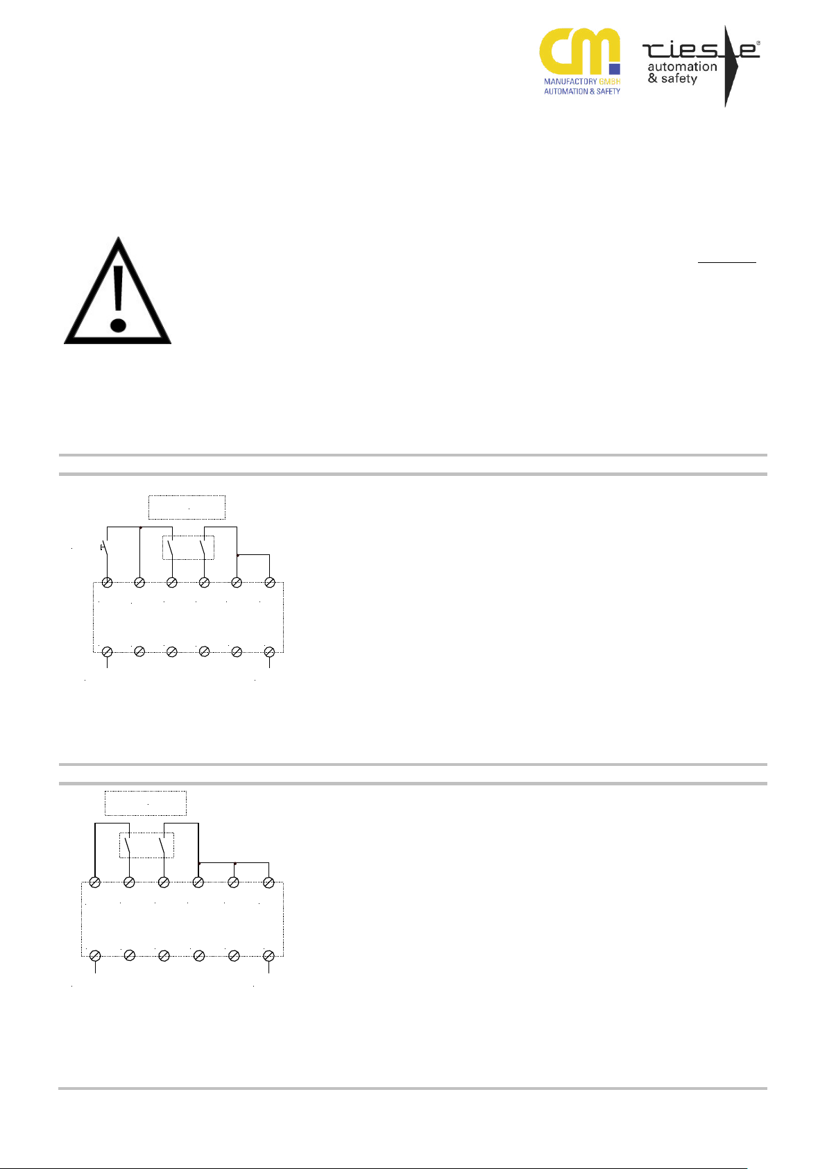
Applikation 1
Application 1
S34 S21S22S12
S11
A1
S33
S35
+24VDC
A2
0VDC
BWS - Empfänger
ESPE receiver
START
S32
S36
S37
2-kanalige Überwachung einer BWS
(Typ 2/4) mit 2 Relaisausgängen, mit
überwachtem Start und Querschlusssicherheit.
Die potentialfreien Relaisausgänge der
BWS müssen an die Eingangskreise
(S11/S12, S21/S22) und der Start-Taster
an den Startkreis (S34/S11) angeschlossen werden. Die Aktivierung der
Ausgänge erfolgt, bei geschlossenen
Relaisausgängen der BWS, nach dem
Schließen und Wiederöffnen des Startkreises (Starttaste). Wird der Lichtweg
unterbrochen, öffnen die Relaisausgänge der BWS und die Halbleiterausgänge
des SAFE CL werden deaktiviert.
Dual channel application for connecting
2 relay outputs of an ESPE (type2/4)
with monitored start circuit and cross
circuit check.
Connect the ESPE outputs to the inputs
S11/S12 and S21/S22 and the start
button to S34/S11.
The safety outputs are activated when
the relay outputs of the ESPE are closed
and the start circuit is closed and reopened. By interrupting the optical path
the outputs of the ESPE open and the
outputs of the SAFE CL are deactivated.
bei Anschluss BWS TYP 4:
Kategorie 4; SIL3; PLe erreichbar
bei Anschluss BWS TYP 2:
Kategorie 2; SIL1; PLd erreichbar
connecting ESPE type 4:
category 4; SIL3; PLe reachable
connecting ESPE type 2:
category 2; SIL1; PLd reachable
Applikation 2
Application 2
S34S21S22S12
S11
A1
S33
S35
+24VDC
A2
0VDC
S32
BWS - Empfänger
ESPE receiver
S37S36
2-kanalige Überwachung einer BWS Typ
2/4 mit 2 Relaisausgängen, mit automatischem Start und Querschlusssicherheit.
Die potentialfreien Relaisausgänge der
BWS müssen an die Eingangskreise
(S11/S12, S21/S22) angeschlossen
werden.
Die Brücke S34-S21 konfiguriert das
Gerät für den automatischen Start. Die
Aktivierung der Halbleiterausgänge des
SAFE CL erfolgt nach der Aktivierung
der Relaisausgänge der BWS.
Wird der Lichtweg unterbrochen, öffnen
die Relaisausgänge der BWS und die
Halbleiterausgänge des SAFE CL werden deaktiviert.
Dual channel application for connecting
2 relay outputs of an ESPE (type2/4)
with automatic start and cross circuit
check.
Connect the ESPE outputs to the inputs
S11/S12 and S21/S22.
The bridge S34-S21 enables the automatic start mode. The activation of the
semiconductor outputs of the Safe CL is
done after the relay outputs of the ESPE
were activated.
By interrupting the optical path the outputs of the ESPE open and the semiconductor outputs of the SAFE CL are
deactivated.
bei Anschluss BWS TYP 4:
Kategorie 4; SIL3; PLe erreichbar
bei Anschluss BWS TYP 2:
Kategorie 2; SIL1; PLd erreichbar
connecting ESPE type 4:
category 4; SIL3; PLe reachable
connecting ESPE type 2:
category 2; SIL1; PLd reachable
Anwendungsbeispiele / Application examples
270416 10
Page 11
SAFE CL
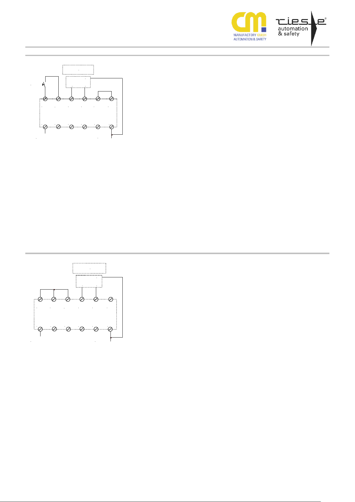
Applikation 3
Application 3
S34 S22S12
S11
A1
S33
S35
+24VDC
A2
START
PNP PNP
GND
0VDC
BWS - Empfänger
ESPE receiver
S32S21
S36 S37
2-kanalige Überwachung einer BWS Typ
2/4 bzw. eines Sicherheitssensors mit 2
PNP-Ausgängen, mit überwachtem Start
Die PNP-Ausgänge des Auslöseelementes müssen an die Eingangskreise S12
und S22) und der Start-Taster an den
Startkreis (S34/S11) angeschlossen
werden.
Die Aktivierung der Ausgänge erfolgt,
bei aktivierten PNP-Ausgängen, nach
dem Schließen und Wiederöffnen des
Startkreises (Starttaste). Ein erneuter
Start ist nur nach gleichzeitiger Deaktivierung und erneuter Aktivierung beider
Eingänge S12, S22 möglich
Dual channel application for monitoring
an ESPE or a safety sensor with 2 pnpoutputs and monitored start.
Connect the pnp-outputs of the ESPE to
input circuit S12/S22 and the start button
to the start circuit S34/S11.
The activation of the outputs results from
closing and re opening the start circuit
by activated pnp-outputs.
A new start is only possible after simultaneous deactivation and new activation
of both inputs S12,S22
bei Anschluss BWS TYP 4:
Kategorie 4; SIL3; PLe erreichbar
bei Anschluss BWS TYP 2:
Kategorie 2; SIL1; PLd erreichbar
connecting ESPE type 4:
category 4; SIL3; PLe reachable
connecting ESPE type 2:
category 2; SIL1; PLd reachable
Applikation 4
Application 4
S34 S22S12
S21
A1
S33
S35
+24VDC
A2
0VDC
PNP PNP
GND
BWS - Empfänger
ESPE receiver
S32
S37
S36
S11
2-kanalige Überwachung einer BWS Typ
2/4 bzw. eines Sicherheitssensors mit 2
PNP-Ausgängen, mit automatischem
Start
Die PNP-Ausgänge des Auslöseelementes müssen an die Eingangskreise S12
und S22) angeschlossen werden. Die
Brücke S34-S21 konfiguriert das Gerät
für den automatischen Start. Die Aktivierung der Halbleiterausgänge des SAFE
CL erfolgt nach der Aktivierung der PNPAusgängen (OSSDs). Eine erneute
Aktivierung der Halbleiterausgänge des
SAFE CL ist nur nach gleichzeitiger
Deaktivierung und erneuter Aktivierung
beider Eingänge S12, S22 möglich.
Dual channel application for monitoring
an ESPE or a safety sensor with 2 pnpoutputs and automatic start.
Connect the pnp-outputs of the ESPE to
input circuit S12/S22. The bridge S34S21 enables the automatic start mode.
The activation of the semiconductor
outputs of the SAFE CL happens after
activating the pnp-outputs (OSSDs).
A new start is only possible after simultaneous deactivation and new activation
of both inputs S12,S22.
bei Anschluss BWS TYP 4:
Kategorie 4; SIL3; PLe erreichbar
bei Anschluss BWS TYP 2:
Kategorie 2; SIL1; PLd erreichbar
connecting ESPE type 4:
category 4; SIL3; PLe reachable
connecting ESPE type 2:
category 2; SIL1; PLd reachable
270416 11
Page 12
SAFE CL
Applikation 5
Application 5
S34 S21S22
S11
A1
S33
+24VDC
A2
START
PNP TEST
GND
S35
0VDC
BWS
ESPE
S32
S36 S37
1-kanalige Überwachung einer BWS Typ
2 bzw. eines Sicherheitssensors mit
einem PNP-Ausgang (OSSD) und zyklischer Testung, mit überwachtem Start
Der Testeingang des Auslöseelementes
muss an den taktenden Ausgangskreis
S21 des SAFE CL und der OSSD des
Auslöseelementes an den Eingangskreis
S22 angeschlossen werden. Die Klemme S12 darf nicht beschalten werden.
Die Brücke S35-S11 konfiguriert das
SAFE CL für die 1-kanalige Applikation.
Der Start-Taster wird an den Startkreis
(S34/S11) angeschlossen. Die Aktivierung der Halbleiterausgänge des SAFE
CL erfolgt, bei aktiviertem OSSD, nach
dem Schließen und Wiederöffnen des
Startkreises (Starttaste).
Zusätzliche Info:
Das Ausgangssignal an S21, welches
mit dem Testeingang bzw. Aktivierungseingang des Auslöseelementes verbunden wird, weist ein periodisches Rechtecksignal mit der Periodendauer von
140ms, einem Impuls von 100ms und
einer Pause von 40ms auf. Das am
Eingang S22, von dem Auslöseelement
zurückgegebene, erwartete Signal darf
maximal 20ms zu dem Ausgangssignal
an S21 verzögert anliegen.
One channel application for monitoring
an ESPE (type 2) or safety sensor with
pnp-output (OSSD) and periodic test and
monitored start.
Connect the test input of the ESPE to
the clocked output S21 of the SAFE CL
and the OSSD of the ESPE to the input
S22. The terminal S12 must not be
used.
The bridge S35-S11 enables the onechannel application mode.
The start button is connected to
S34/S11. The activation of the semiconductor outputs of the SAFE CL results
from closing and re-opening the start
circuit while the OSSD is activated.
Additional information: The output signal
from S21, which is connected with the
test input or with the activation input of
the ESPE, is a square wave signal with
the period duration of 140ms, an impulse
of 100ms and a break of 40ms.
The signal, read in at S22 from the ESPE, must be delayed 20 ms at maximum
to the source signal at S21.
Kategorie 2; SIL1; PLd erreichbar
category 2; SIL1; PLd reachable
Applikation 6
Application 6
S34S21S22
S11
A1
S33
+24VDC
A2
PNP TEST
GND
S35
0VDC
BWS
ESPE
S32
S36 S37
1-kanalige Überwachung einer BWS Typ
2 bzw. eines Sicherheitssensors mit
einem PNP-Ausgang (OSSD) und zyklischer Testung, mit automatischem Start
Der Testeingang des Auslöseelementes
muss an den taktenden Ausgangskreis
des SAFE CLs S21 und den PNPAusgang des Auslöseelementes an den
Eingangskreis S22 angeschlossen werden. Die Klemme S12 darf nicht beschaltet werden. Die Brücke S34-S21
konfiguriert das SAFE CL für den automatischen Start, die Brücke S35-S11 für
die 1-kanalige Applikation. Die Aktivierung der Halbleiterausgänge des SAFE
CL erfolgt nach der Aktivierung des
PNP-Ausganges des Auslöseelemtentes.
Zusätzliche Info:
Das Ausgangssignal an S21, welches
mit dem Testeingang bzw. Aktivierungseingang des Auslöseelementes verbunden wird, weist ein periodisches Rechtecksignal mit der Periodendauer von
140ms, einem Impuls von 100ms und
einer Pause von 40ms auf.
Das am Eingang S22, von dem Auslöseelement zurückgegebene, erwartete
Signal darf maximal 20ms zu dem Ausgangssignal an S21 verzögert anliegen.
One channel application for monitoring
an ESPE (type 2) or safety sensor with
pnp-output (OSSD) and periodic test and
automatic start.
Connect the test input of the ESPE to
the clocked output circuit S21 and the
pnp-output to the input circuit S22. The
terminal S12 must not be used. The
bridge S34-S12 enables the automatic
start mode and the bridge S35 –S11
enables the one channel application.
The activation of the semiconductor
outputs happens after the activation of
the pnp-output of the ESPE.
Additional information: The output signal
from S21, which is connected with the
test input or with the activation input of
the ESPE, is a square wave signal with
the period duration of 140ms, an impulse
of 100ms and a break of 40ms.
The signal, read in at S22 from the ESPE, must be delayed 20 ms at maximum
to the source signal at S21.
Kategorie 2; SIL1; PLd erreichbar
category 2; SIL1; PLd reachable
270416 12
Page 13
SAFE CL
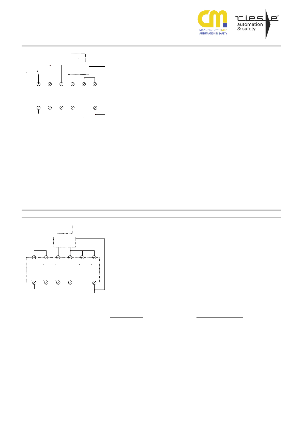
Applikation 7
Application 7
S34 S22S12
S11
A1
S33
S35
+24VDC
A2
0VDC
START
PNP PNP
GND
K2
K1
14
34
K1
K2
S32S21
BWS - Empfänger
ESPE receiver
S36
S37
2-kanalige Überwachung einer BWS Typ
2/4 bzw. eines Sicherheitssensors mit 2
PNP-Ausgängen, mit überwachtem Start
und Kontakterweiterung.
Die PNP-Ausgänge des Auslöseelementes müssen an die Eingangskreise S12 und S22) und der Start-Taster an
den Startkreis (S34/S11) angeschlossen
werden. Die Aktivierung der Ausgänge
erfolgt, bei aktivierten PNP-Ausgängen,
nach dem Schließen und Wiederöffnen
des Startkreises (Starttaste).
Ein erneuter Start ist nur nach gleichzeitiger Deaktivierung und erneuter Aktivierung beider Eingänge S12, S22 möglich
Zur Überwachung der externen Schützkontakte werden die Öffner-Kontakte der
zwangsgeführten Schütze in den Startkreis eingebunden.
Dual channel application for monitoring
an ESPE with monitored start circuit,
cross circuit check and contact expansion.
Connect the pnp-outputs of the ESPE to
the input circuits S12 and S22 and the
start button to the start circuit S34/S11.
The activation of the outputs results from
closing and re opening the start circuit
by activated pnp-outputs.
A new start is only possible after simultaneous deactivation and new activation
of both inputs S12 and S22.
For monitoring the external conductors,
the NC contacts of the positively driven
contactors must be in series to the start
button. forcibly guided contacts
Kategorie 4; SIL3; PLe erreichbar
category 4; SIL3; PLe reachable
Beispiel für den Anschluss von
Schützen und deren Überwachung
siehe Applikation 7
Wiring example for external contactors and monitoring of them, see
application no. 7
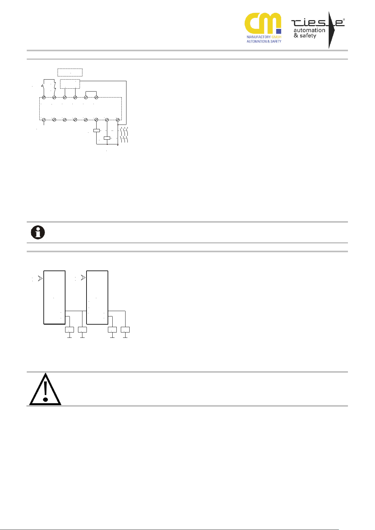
Applikation 8
Application 8
S32
S33
24
S11
K1
K2
K3
K4
14
A
B
24
14
safety
input
safety
input
Logische UND-Verknüpfung zweier
Geräte.
Wird das Auslöselement von Gerät A
betätigt fallen K1/K2 ab. Da die Sicherheitsausgänge von Gerät A jetzt ein 0VPotential anliegen haben und das Gerät
B durch die offene Klemme S32 für eine
UND-Verknüpfung konfiguriert wurde,
werden die Schütze K3/K4 über den
Anschluss S33 (logische UNDVerknüpfung) abgeschaltet. Wird hingegen nur das Auslöselement an B geöffnet, schalteten auch nur die Schütze
K3/K4 ab. Die Schütze K1/K2 bleiben
weiterhin angezogen. Das Gerät A
schaltet somit alle ihm nachfolgenden
Geräte ab.
Logical AND circuit of two devices.
After opening the release switch circuits
of device A, the contactors K1/K2 deenergise. Because the safety outputs of
device A have now a 0V-potential and
the device B is configured for the ANDcombination (due to the open circuit
S32), the contactors K3/K4 will be deenergised over the S33 terminal (AND
combination) too. If only the release
switch of device B will be opened, the
contactors K3/K4 will be de-energised
only. The contactors K1/K2 remains in
energised condition. Hence device A deenergises all its following devices.
Kategorie 4; SIL3; PLe erreichbar
category 4; SIL3; PLe reachable
Bei Verwendung von mehreren untereinander verknüpften Geräten mit
unterschiedlichen Kategorien gilt
jeweils die niedrigste Kategorie für
die gesamte Schaltung
By use of several interconnected
devices with different category the
lowest category counts in each case
to the whole circuit
Verknüpfungssbeispiel / Combination example
Bitte Beachten Sie auch Punkt 3 auf Seite 4 Montage und Inbetriebnahme: Please notice item 3 on Page 4: Mounting and start-up
270416 13
Page 14

 Loading...