

Page 1

SAFE 2
Safe 2
13 23
Power
riese
13 23 24
14 S11 S12
S21 S22 A2
A1 S33 S34
Channel
1
Channel
2
14 24
CM Manufactory GmbH
Otto-Hahn-Str. 3
D-72406 Bisingen
Tel. +49-(0)7476-9495-0
Fax. +49-(0)7476-9495-195
www.automation-safety.de
Zielgruppe/
Target audience
Zeichenerklärung/
Explanation of
signs
270416 1
Einleitung
Diese Betriebsanleitung soll Sie mit den
Not-Halt-Sicherheitsrelais und Schutztürwächter SAFE 2 / SAFE 2.1 bzw. dem
Nachschaltgerät für Sicherheitsmatten
SAFE 2.2 vertraut machen.
Die Betriebsanleitung richtet sich an folgende Personen:
Qualifizierte Fachkräfte, die Sicher-
heitseinrichtungen für Maschinen und
Anlagen planen und entwickeln und
mit den Vorschriften über Arbeitssicherheit und Unfallverhütung vertraut
sind.
Qualifizierte Fachkräfte, die Sicher-
heitseinrichtungen in Maschinen und
Anlagen einbauen und in Betrieb
nehmen.
In dieser Betriebsanleitung werden einige
Symbole verwendet, um wichtige Informationen hervorzuheben:
Dieses Symbol steht vor Textstellen, die
unbedingt zu beachten sind. Nichtbeachtung führt zur Verletzung von Personen
oder zu Sachbeschädigung
Dieses Symbol kennzeichnet Textstellen,
die wichtige Informationen enthalten.
Dieses Zeichen kennzeichnet auszuführende Tätigkeiten
Nach diesem Zeichen wird beschrieben,
wie sich der Zustand nach einer ausgeführten Tätigkeit ändert.
© Copyright Alle Rechte vorbehalten. Änderungen, die
dem technischen Fortschritt dienen, vorbehalten.
Original Bedienungsanleitung
Sicherheitsschaltgerät für Not-HaltKreise und Schutztürüberwachungskontakte (SAFE 2 / 2.1)
Sicherheitsschaltgerät für Sicherheitsschaltmatten und Sicherheitsleisten (SAFE 2.2)
Original operating instructions
Safety controller for e-stop and safety
gate monitoring applications
(SAFE 2 / 2.1)
Safety controller for mat- and contact
edges (SAFE 2.2)
Introduction
This operating instruction should make
you familiar with the emergency stop and
safety gate monitoring relays SAFE 2 /
SAFE 2.1, respectively the mat-control
relay SAFE 2.2.
The operating instruction is addressed to
the following persons:
Qualified professionals who plan and
develop safety equipment for machines and plants and who are familiar with the safety instructions and
safety regulations.
Qualified professionals, who install
safety equipment into machines and
plants and put them into operation.
The operating instruction contains several symbols which are used to high-light
important information:
This symbol is placed in front of text
which has to be absolutely paid attention
to. Nonobservance leads to serious injuries or damage to property.
This symbol is placed in front of text,
which contains important information.
This sign is placed in front of activities
After this sign follows a description on
how the situation has changed after an
activity is performed.
© Copyright All rights reserved. Changes, which serve
technical improvements are reserved.
Page 2

SAFE 2
Bestimmungsgemäße
Verwendung
Application:
Zu Ihrer Sicherheit
For your safety
Sicherheitshinweise
Das Sicherheitsrelais SAFE 2 / 2.1 / 2.2 sind
bestimmt für den Einsatz in:
SAFE 2 mit Überwachung der Start
Taste
SAFE 2.1 ohne Überwachung der
Start Taste
SAFE 2.2 ohne Überwachung der
Start Taste
SAFE 2 / 2.1
Ein- oder Zweikanalige Schaltungstech-
nik für Not-Halt-Schalter
Ein- oder Zweikanalige Schaltungstech-
nik mit Grenztaster für Schiebeschutzgitter.
SAFE 2.2
Ein- oder Zweikanalige Schaltungstech-
nik für Sicherheitsmatten.
Ein- oder Zweikanalige Schaltungstech-
nik für Sicherheitsleisten.
Personen - und Sachschutz sind nicht mehr
gewährleistet, wenn das Sicherheitsrelais
nicht entsprechend seiner bestimmungs-
gemäßen Verwendung eingesetzt wird.
Beachten Sie unbedingt die folgenden Punkte:
Das Gerät darf nur unter Beachtung
dieser Betriebsanleitung von Fachpersonal installiert und in Betrieb genommen
werden, welches mit den geltenden Vorschriften über Arbeitssicherheit und Unfallverhütung vertraut ist. Elektrische Arbeiten dürfen nur von Elektrofachkräften
durchgeführt werden.
Beachten Sie die jeweils gültigen Vor-
schriften, insbesondere hinsichtlich der
Schutzmaßnahmen.
Reparaturen, insbesondere das Öffnen
des Gehäuses, dürfen nur vom Hersteller
oder einer von ihm beauftragten Person
vorgenommen werden. Ansonsten erlischt jegliche Gewährleistung.
Vermeiden Sie mechanische Erschütte-
rungen beim Transport oder im Betrieb;
Stöße größer als 5g / 33Hz können zur
Beschädigung des Gerätes führen.
Montieren Sie das Gerät in einem staub-
und feuchtigkeitsgeschütztem Gehäuse;
Staub und Feuchtigkeit kann zu Funktionsstörungen führen.
Sorgen Sie für eine ausreichende
Schutzbeschaltung bei kapazitiven und
induktiven Lasten an den Ausgangskontakten.
Applikationen beachten
Safety indications
The safety relay SAFE 2 / SAFE 2.1 / SAFE
2.2 can be used for:
SAFE 2 with monitoring of the start
bottom
SAFE 2.1 without monitoring of the
start bottom
SAFE 2.2 without monitoring of the
start bottom
SAFE 2 / 2.1
Single or dual- channel capability for
emergency stop.
Single or dual- channel capability with
limit switches for safety gates.
SAFE 2.2
Single or dual- channel capability for
safety mats.
Single or dual- channel capability for
safety contact edges.
Person and object – protection aren’t guaran-
tee, if the safety relay isn’t use by adequate
define application.
Please note the following points:
The unit should only be installed and
operated by persons, who are familiar
with both these instructions and the current regulations for safety at work and
accident prevention.
Follow local regulations as regards pre-
ventative measures.
Any guarantee is void following opening
of the housing or unauthorized modifications.
Avoid mechanical vibrations greater than
5 g / 33 Hz when transporting and in operation.
The unit should be panel mounted in an
enclosure rated at IP 54 or better, otherwise dampness or just could lead to function impairment.
Adequate fuse protection must be pro-
vided on all output contacts with capacitive and inductive loads.
Look for the applications
270416 2
Page 3

SAFE 2
Überwachungslogik /
control logic
~ ~
S21
~
~
+
=
K1
A1
(+)
elektr.
Sicherung /
electronic
fuse
A2
(-)
S11 S12
14
K2
K2
24
K1
S34S22
S33 13 23
13-14, 23-24
Aufbau und Funktionsweise
Ausgangskontakte:
Sicherheitsstrompfade (Schließer)
Für das Betreiben des Gerätes muß eine
Hilfsspannung an die Klemmen A 1 und
A 2 angelegt werden. Die LED `Netz`
leuchtet. An der Klemme S11 steht dann
eine Spannung von 24 V DC zur Verfügung. S12 und S22 werden nach den
entsprechenden Anwendungsbeispielen
beschaltet.
Zum START des Gerätes muß die
Klemme S33 mit S34 über einen Schließerkontakt überbrückt werden.
Danach sind die Kontakte 13-14, 23-24
geschlossen. Die LED`s Kanal 1 und
Kanal 2 leuchten.
In Reihe zu dem START-Taster an den
Klemmen S33 und S34 kann die Schaltung eines externen Schützes überwacht
werden (siehe Anwendungsbeispiel 3).
Assembly and function
(function circuit diagram)
Output contacts:
safety circuits (normally open)
An supply voltage must be applied to
terminals A 1 and A 2. Power LED illuminates and 24 V DC is available at terminal S11. Terminals S12 and S22 must be
connected according to the application
example selected to meet the application
requirement.
To START the unit, terminals S33 and
S34 must be bridged with a normally
open contact. The unit works if you close
this contact.
At this time the contacts 13-14, 23-24 are
closed. The LED’s channel 1 illuminate,
channel 2 illuminate.
In series to this START-button an external contactor can be controlled
(see application 3).
270416 3
Page 4
SAFE 2
Safe 2
13 23
Power
riese
13 23 24
14 S11 S12
S21 S22 A2
A1 S33 S34
Channel
1
Channel
2
14 24
automatische Aktivierung / automatic activation
S33
S34
Start über Start-Taste / start with start button
S34
S33
Start
Start über Start-Taste und Anschluß
Maschinenfreigabekreise / Schützkontrolle
start with start button and contact expansion
S34
S33
Start
K2 ext
K1 ext
Mechanische
Montage /
mechanical
mounting
Elektrischer
Anschluß
Electronic
connection
270416 4
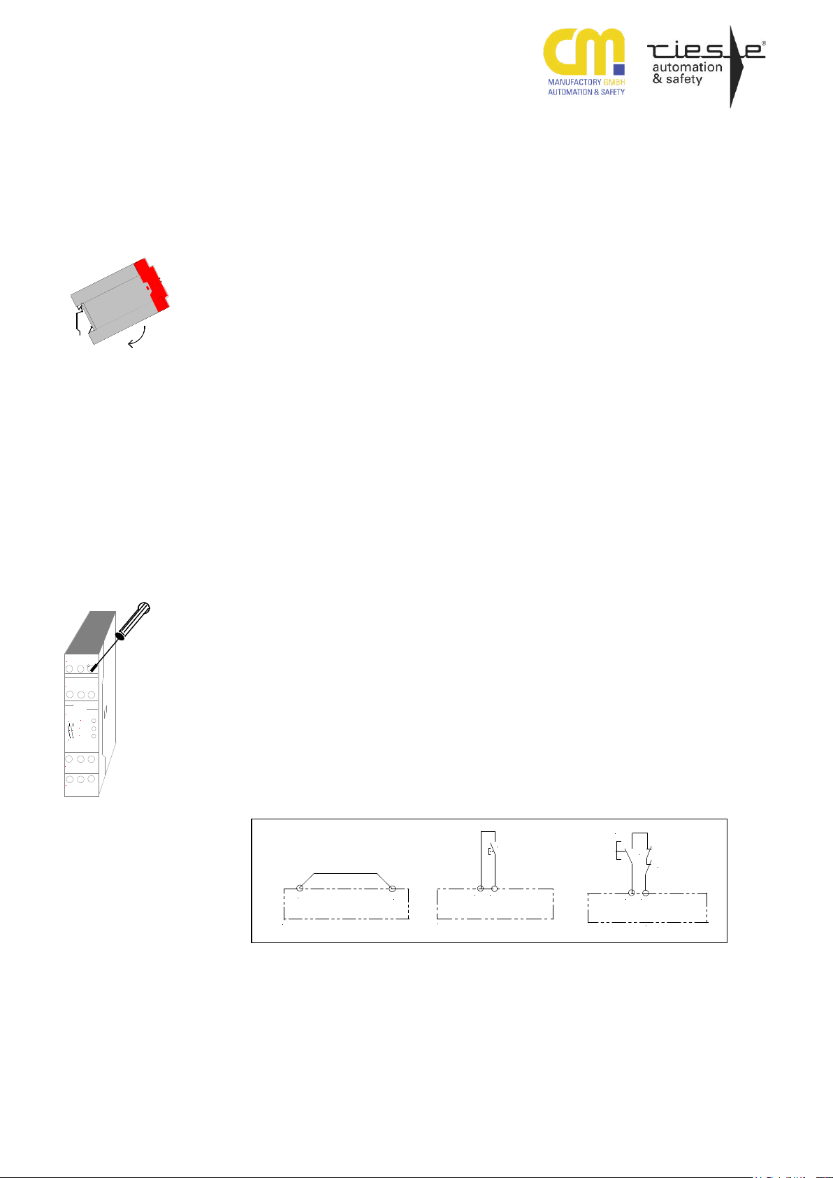
Montage und Inbetriebnahme
Für eine sichere Funktion muß das Sicherheitsrelais in ein staub- und feuchtigkeitsgeschütztes Gehäuse eingebaut
werden (IP54).
lais auf eine Normschiene
Führen Sie die Verdrahtung entsprechend des Verwendungszweckes durch.
Orientieren Sie sich dabei an den Anwendungsbeispielen. Generell ist das
Sicherheitsrelais nach folgenden Angaben zu verdrahten:
1. Aktivierungs- und Rückführungskreis
Montieren Sie das Sicherheitsre-
schließen
Automatische Aktivierung:
S33 – S34 brücken oder externe
Schütze schließen.
Bedingte Aktivierung:
Taster an S33 – S34 anschließen
(keine Brücke an S33 – S34). Externe Schütze werden in Reihe
zum START-Taster an die
Klemmen S33 –S34 angeschlossen.
Mounting and opening
The unit should be panel mounted in an
enclosure rated at IP 54 or better, otherwise dampness or dust could lead to
function impairment.
There is a notch on the rear of
the unit for DIN-Rail attachment.
Carry out the wire appropriate the use.
According to the examples of application.
General the safety-relay has to be wire
under following specifications:
1. Close the feedback control loop and
the activation circuit
Automatic activation:
bridge S33 – S34
Conditional activation:
Connect button on S33 – S34 (no
bridge on S33 – S34). N.C. contacts of external contactors are
wired in series with the STARTbutton and terminals
S33 – S34.
Page 5

SAFE 2
Safe 2
13 23
Power
riese
13 23 24
14 S11 S12
S21 S22 A2
A1 S33 S34
Channel
1
Channel
2
14 24
S11 S12 S22 S21
zweikanalig / dual-channel
Auslöseelement
trigger
element
einkanalig / single-channel
A1 (+) A2 (-)
24 VAC/DC24 VAC/DC
Auslöseelement /
trigger
element
Eingangskreis schließen (Safe 2/2.1)
Einkanalig: Schließen Sie den
Kontakt des Auslöseelementes positive
Versorgungsspannung und A1 (+) an.
Zweikanalig: Schließen Sie die
Kontakte des Auslöseelementes
an S11-S12 und S21-S22 an.
Die Verdrahtung der Versorgungsspannung ist abhängig vom Gerätetyp
(s. Typenschild am Gerät).
2. Versorgungsspannung Uv 24V
AC/DC
Close input circuit (Safe 2/2.1)
Single-channel: connect contact
from trigger element to positive
supply voltage and A1(+)
Dual-channel connect contacts
from trigger element to
S11 - S12 and S21 - S22.
The wire of the supply voltage is
dependent on device-model
(see type plate on the device).
2. Supply voltage Uv 24V AC/DC
Einkanalig: Schließen Sie die
Versorgungsspannung U v+ U v
N über den Kontakt des Auslöseelementes an die Klemme A1
und U v- U v N (Null-Leiter) an
die Klemme A2 an.
Zweikanalig: Schließen Sie die
Versorgungsspannung an die
Klemmen A1 und A2 an.
Beachten Sie unbedingt die maximalen
Leitungslängen.
An die Klemme S11 darf kein zusätzlicher Verbraucher angeschlossen werden
Single-channel: The Supply voltage Uv + Uv N has to be connected over the contact from
trigger element to the terminals
A1 and U v- directly to the
terminal A2.
Dual-channel: The Supply voltage has to be connected to the
terminals A1 and A2.
Please note the max. lengths of the cables.
At the terminal S11 it’s not allowed to add
additional consumer.
270416 5
Page 6
SAFE 2
1.
1.
2.
3.
Erdschluß bei
AC - DC-Variante
(mit elektr. Sicherung) /
Earth fault
AC / DC-version
(with electronic fuse
protection)
Fehlfunktion der
Kontakte /
Faulty contact
functions
Nur eine oder
keine LED brennt /
Only one or no
LED illuminates
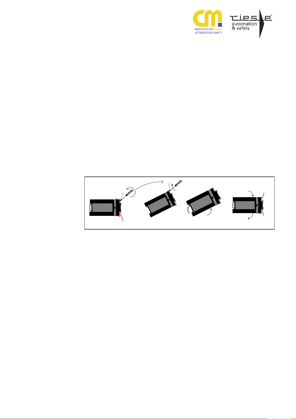
Wartung und Reparatur
Das Sicherheitsrelais arbeitet wartungsfrei.
Zum Austausch des Gerätes empfehlen
wir die Kabel 1 zu 1 abzuschrauben und
an das Austauschgerät anzuschrauben.
das Austauschgerät an
schrauben.
Gerät von der Normschiene.
auf die Normschiene
1. Kabel abschrauben und an
2. Nehmen Sie das defekte
3. Montieren Sie das neue Gerät
Fehler/Störungen, Auswirkung
und Maßnahmen
Die Sicherung löst aus. Die Ausgangskontakte öffnen. Nach Wegfall der Störursache und Einhalten der Betriebsspannung ist das Gerät wieder betriebsbereit.
Bei verschweißten Kontakten ist nach
Öffnen des Ausgangskreises keine neue
Aktivierung möglich.
Externer Beschaltungsfehler oder interner Fehler. Externe Beschaltung prüfen.
Wenn Fehler immer noch vorhanden,
Gerät an CM Manufactory GmbH einschicken.
Maintenance and repair
The safety- relay function maintenancefree.
For exchange of the device, we advisable
the terminals 1 to 1 screw of and screw
on the exchange-device.
and screw on the exchange
device.
vice from the DIN-Rail.
DIN-Rail.
1. You must screw off the cable
2. Take away the defective de
3. Mount the new device on the
Faults, effect and measures
An electronic fuse release the output
contacts to open. Once the reason of the
disturbance is removed and the rated
voltage is observed, the device is ready
for operation.
In the case of welded contacts, further
activation is not possible following an
opening of the input circuit.
External wiring fault or internal fault is
present. Test the external wiring.
When the flaw is still available, send the
device to CM Manufactory GmbH.
270416 6
Page 7

SAFE 2
Elektrische Daten / electrical data
Versorgungsspannung Uv / supply voltage
24 V AC/DC (elektronische Sicherung)
24 V AC/DC (electronic fuse protection)
Spannungsbereich / voltage range
0,90 ...1,1 UB
Frequenz (AC-Variante) / frequency (AC-type)
50 ... 60 Hz
Leistungsaufnahme ca. / power consumption appr.
ca. 2,5 VA / 2,5 W
Leitungsdaten / conductor data
Leiteranschluß / conductor connection
2 x 1,5 mm2 Massivdraht (Cu) / massive wire DIN VDE 0295
2 x 1,5 mm2 Litze (Cu) mit Hülse / strand with hull DIN VDE 46228
Use 60/75°C copper wire only!
Max. Leitungslängen (Eingangskreis) /
max. conductor length (input circuit)
Leiterquerschnitt / conductor cross-section
2 x 1,5 mm2 / 4 x 1,5mm²
Kapazität / capacity
150 nF/km
Widerstand / resistance
11,7 Ohm /km
Temperatur / temperature
+ 25°C
Max. Leitungslänge / conductor length
2 x 100m (einkanalig) / (single channel)
4 x 100m (zweikanalig) / (dual channel)
Kontaktdaten / contact data
Kontaktbestückung / contact-allocation
2 Schließer / 2 normally safety open
Kontaktart / contact type
Relais zwangsgeführt / relay positive guided
Kontaktmaterial / contact material
AgSnO2 oder vergleichbares Material /
AgSnO2 or comparable material
Schaltspannung / switching voltage
250V AC, 24V DC
Schaltstrom / switching current
6 A
Max. Schaltvermögen / max. switching capability
DIN EN 60947-5-1
AC 14 230 V / 5,0 A
DC 13 24 V / 1,5 A
Schaltleistung max. / max. switching capacity
1500 VA (ohmsche Last) / 1500 VA (ohm load)
Mechanische Lenbensdauer / mechanical lifetime
107 Schaltspiele / switches
Kriech- und Luftstrecken / creeping distance and
clearance
-DIN VDE 0160 - für Verschmutzungsgrad 2,
at pollution grade 2.
- Basisisolierung: -Überspannungskategorie 3 / 250 V,
- basic isolation: -over voltage category 3 / 250 V.
Kontaktabsicherung / contact security
6,3 A flink oder 4 A träge DIN VDE 0660 Teil 200
6,3 A brisk or 4 A inert DIN VDE 0660 part 200
Kurzschlusssicherung / Short Circuit Withstand
Short circuit protection acc. IEC60947-5-1
Weld-free protection at IPSCC ≥1kA with
Fuse links, size D01; utilization category gL/gG
acc.IEC60269-1; IEC60269-3-1; VDE036-T301
Schließer / NO-contacts: 10A
Öffner / NC-contacts: 6A
Spannung an S11 / voltage on S11
24V DC
Rückfallverzögerung K1/delay on deenergisation K1
< 30 ms (Beispiel/Example 1 & 2 < 70 ms)
Synchronisationszeit in Reihenfolge S22 und S12
simultaneousness in series S22 and S 12
ca. 40 ms
Wiederbereitschaftszeit (minimale Abschaltzeit der Eingänge) / restarting readines time (minimum switch off time the
inputs)
0,5 s
Mechanische Daten / mechanical data
Gehäusematerial / housing material
Noryl SE 100
Abmessungen (BxHxT) in mm / dimensions ( bxhxd )
22,5 x 80 x 99
Befestigung / fastening
Schnappbefestigung für Normschiene / click-fastening for DIN-Rail
Max. Anzugsdrehmoment / max. tighening torque
0,4 Nm (Tighten to 1 N.m. Overtorquing may cause enclosure breakage.)
Gewicht mit Klemmen / weight with terminals
Max. 185g
Lagerung / storage
In trockenen Räumen / in dry areas
Umgebungsdaten / environmental data
Umgebungstemperatur / operating temperature
-25°C ... +55°C
Schutzart Klemmen / terminal type
IP 20 DIN VDE 0470 Teil 1 / part 1
Schutzart Gehäuse / housing type
IP 40 DIN VDE 0470
Stoßfestigkeit / shock resistance
5g, 33 Hz VDE 0160
Zertifizierungen / certifications
Geprüft nach / tested in accordance with
EN ISO 13849-1
Erreichtes Level/Kategorie / achieved level/category
Performance Level e, Kat.4
MTTFd [Jahre] / MTTFd [years]
69 “hoch/high“
DC
99% “hoch/high“
CCF
erfüllt/achieved
Technische Daten / Technical Data
270416 7
Page 8

SAFE 2
4133
START
S34S33
S22
S21
S12
S11
23
13
Not-
STOP
E-
Halt/
A2(-)A1(+)
Ub
24V AC/DC
A2(-)
S34 S33
A1(+)
START
S1
S22 S21S12 S11
23
13
4133
START
S34S33
A2(-)A1(+)
24V AC/DC
S22S21 S12S11
23
13
NOT-
STOP
E-
AUS/
bis Kategorie 2; SIL1; PLd erreichbar
up to category 2; SIL1; PLd reachable
bis Kategorie 2; SIL1; PLd erreichbar
up to category 2; SIL1; PLd reachable
bis Kategorie 4; SIL3; PLe erreichbar
up to category 4; SIL3; PLe reachable
Anwendungsbeispiele
Beispiel 1: Einkanalige
Not-Halt-Schaltung (ohne Querschlußsicherheit). Safe 2/2.1
Mit dem Starttaster wird das Gerät
aktiviert. Über den Not-Halt-Schalter
fallen die Kontakte in ihre Grundstellung zurück.
Rückfallverzögerung < 70 ms *
Beispiel 2: Einkanalige Schutztürüberwachung(ohne Querschlußsicherheit). Safe 2/2.1
Wird der Schutztürtaster S1 geschlossen,
bleiben die Ausgangskontakte unverändert. Erst mit Freigabe wird
das Gerät aktiviert. Die Kontakte1314,23-24 schließen. Beim Öffnen
des Schutztürtasters fallen die Kontakte unverzögert in ihre Grundstellung zurück.
Rückfallverzögerung < 70 ms
Ergänzender Hinweis
Bei entsprechender Verdrahtung
nach Applikationsbeispielen 1 und 2
muss durch den Anwender eine
Anbindung an die Maschinensteuerung für die zyklische Testung erfolgen.
Beispiel 3: Zweikanalige Not-HaltSchaltung (mit Querschlußsicherheit). Safe 2/2.1
Bei der zweikanaligen Not-HaltSchaltung mit Querschlußsicherheit
wird der Klemmenanschluß S11,
S12, S21 und S22 verändert. Mit
dem START-Taster wird das Gerät
aktiviert. Die Kontakte 13-14 und
23-24 schließen. Über den Not-HaltSchalter fallen die Kontakte in ihre
Grundstellung zurück.
Examples for applications
Example 1: Single-channel emergency stop (without opposite
between channels). Safe 2/2.1
Pressing the START-button, the unit
will be activated. Contacts 13-14
and close. Pressing the emergency
stop will reset the contacts.
delay on deenergisation < 70 ms *
Example 2: Single-channel safety
gate monitoring. Safe 2/2.1
If the button S1 of the safety gate is
closed the output contacts do not
change. Pressing the START-button
activates the SAFE2. The contacts
13-14,23-24 close.
After the opening of the protection
door switch the contacts return to
their normal position without delay.
delay on deenergisation < 70 ms
Additional advice
With wiring according to application
examples 1 and 2 the user must
provide a connection to the machine
control for cyclic testing.
Example 3: Dual-channel emergency stop (with opposite between channels). Safe 2/2.1
For this application the terminal
wiring S11, S12, S21 and S22 is
changed. With the START-button
the device will be activated The
contacts 13-14 and 23-24 are
closed. Pressing the emergency
stop initiates a stop and outputs
open immediately.
270416 8
Page 9

SAFE 2
NOT-
STOP
AUS/
E-
S
ext.
ext.
U
24V AC/DC
START
K1 ext.
K2 ext.
S33 S34
A1(+)
S11
A2(-)
S21 S22
23
ext.
K2
24
K1
ext.
S12
13
1414
33 41
24V AC/DC
A2(-)
S34 S33
A1(+)
Freigabe/
release
S22 S21S12 S11
23
13
S2S1
24V AC/DC
A2(-)
S34 S33
A1(+)
S22 S21S12 S11
23
13
S2S1
bis Kategorie 4; SIL3; PLe erreichbar
up to category 4; SIL3; PLe reachable
bis Kategorie 4; SIL3; PLe erreichbar
up to category 4; SIL3; PLe reachable
bis Kategorie 4; SIL3; PLe erreichbar
up to category 4; SIL3; PLe reachable
Beispiel 4: Zweikanalige Not-HaltSchaltung mit externer Kontakterweiterung (2Schütze), Kontaktüberwachung und Querschlußsicherheit. Safe 2/2.1
In diesem Beispiel werden zwei
externe Schütze mit Kontaktzwangsführung verwendet. Je
ein Öffnerkontakt dieser beiden
Schütze muß in Reihe zum STARTTaster an die Klemmen S33 und
S34 angeschlossen werden. Über
einen Schalter S ext. können die
externen Schütze zu einem beliebigen Zeitpunkt dazugeschalten bzw.
abgeschalten werden, wenn das
SAFE 2... aktiviert ist. Die Anschlußleitungen für die Schütze sollten zur
Vermeidung von Querschlüssen
getrennt verdrahtet werden.
Beispiel 5: Zweikanalige Schutztürüberwachung (mit Querschlußsicherheit). Safe 2/2.1
Werden die Schutztürschalter S1
und S2 geschlossen, bleiben die
Ausgangskontakte unverändert. Erst
mit Freigabe wird das Gerät aktiviert. Die Kontakte13-14,23-24
schließen. Beim Öffnen des Schutztürtasters fallen die Kontakte unverzögert in ihre Grundstellung zurück.
Beispiel 6: Zweikanalige Schutztürüberwachung mit automatischer Aktivierung und Querschlußsicherheit. Safe 2.1
In diesem Beispiel erfolgt die Aktivierung des Gerätes automatisch,
da S33 und S34 überbrückt sind.
Wird der Schutztürtaster geschlossen, schließen die Kontakte 13-14
und 23-24. Beim Öffnen des Schutztürtasters fallen die Kontakte unverzögert in ihre Grundstellung zurück.
Dieses Anwendungsbeispiel ist nur
mit der Gerätevariante SAFE 2.1
ohne Überwachung der STARTTaste möglich.
Example 4: Dual-channel emergency stop with external contact
extension (2 contactors), contact
monitoring and opposite polarity
between channels. Safe 2/2.1
This application uses two external
contactors with positive guidance.
One normally closed contact of each
external contactors must be connected in series to the STARTbutton to the terminals S33 and
S34. Through the switch S ext. the
external contactors can be operated
or turned off at any time if the SAFE
2... is activated.
Example 5: Dual-channel protection door monitoring with opposite polarity between channels.
Safe 2/2.1
If the safety gate switches are
closed, the output contacts remain
unchanged. After the release of the
unit, the contacts 13-14 and 23-24
close. After opening the protection
door switches the contacts return to
their normal position without delay.
Example 6: Dual-channel protection door monitoring with automatic activation and with opposite polarity between channels.
Safe 2.1
For this application the unit SAFE
2.1 has to be used. The activation
works automatically, since the terminals S33/S34 are bridged. If the
protection door switches close, the
contacts 13-14, 23-24 close. After
the opening of the protection door
switches the contacts return to their
normal position without delay.
270416 9
Page 10

SAFE 2
A1(+)
S33
S34
A2(-)
S21
24V AC/DC
S11 S22
23
S12
13
A1(+)
S33S34
A2(-)
S21
24V AC/DC
S11 S22
23
S12
13
bis Kategorie 4; SIL3; PLe erreichbar
up to category 4; SIL3; PLe reachable
.
bis Kategorie 1; SIL1; PLc erreichbar
up to category 1; SIL1; PLc reachable
Beispiel 7: Zweikanalige Sicherheitsschaltung für VierdrahtSicherheitsmatten (mit Querschlußsicherheit). Safe 2.2
Dieses Anwendungsbeispiel ist nur
mit der Gerätevariante SAFE 2.2
möglich.
In diesem Beispiel erfolgt die Aktivierung des Gerätes automatisch,
da S33-S34 überbrückt sind. Die
Kontakte13-14, 23-24 schließen
nach Einschalten der Spannung
falls die Sicherheitsmatte nicht betreten wird. Bei Betreten der Matte
fallen die Ausgangskontakte ab.
Beispiel 8: Einkanalige Sicherheitsschaltung für ZweidrahtSicherheitsmatten mit Querschlußsicherheit. Safe 2.2
Dieses Anwendungsbeispiel ist nur
mit der Gerätevariante SAFE 2.2
möglich.
Bei dieser Schaltung werden die
zwei Anschlüsse pro Kanal an jeweils eine Klemme der Sicherheitsmatte angeschlossen (S21-S22 und
S11-S12 werden gebrückt). Die
Funktion ist die gleiche wie in Anwendungsbeispiel 7.
Example 7: Dual-channel application for four-wire-safety-mats
(with oppositepolarity between
channels). Safe 2.2
This application is only possible with
SAFE 2.2.
The activation works automatically,
since the terminals S33 -S34 are
bridged. Contacts 13-14, 23-24
close after power is on or after steps
off the safety mat is stepped on the
contacts fall back into their normal
position without delay.
Example 8: Single-channel application for two-wire-safety-mats
(with oppositepolarity between
channels). Safe 2.2
This application is only possible with
SAFE 2.2.
In this apllication the two connections per channel are each connected to one of the terminals of the
safety mat. The terminals S21-S22
and S11-S12 are connected.
The function is like the application
with the four-wire safety-mats
270416 10
Page 11

Page 12

 Loading...