


Istruzioni per installazione, uso e manutenzione
Anleitungen fŸr Einbau, Betrieb und Wartung
Installation, use and maintenance instructions
Instructions pour installation, utilisation et entretien
Bruciatori di gasolio
…lbrenner
Light oil burners
Bržleurs ˆ Þoul domestique
Funzionamento bistadio
ZweistuÞger Betrieb
Two-stage operation
Fonctionnement ˆ deux allures
CODICE - CODE
3475611 RL 190 673 T1
MODELLO - MODELL
MODEL - MODELE
TIPO - TYP
TYPE - TYPE
2915640 6-98


3
I
INDICE
D
INHALT
DATI TECNICI . . . . . . . . . . . . . . . . . . . . . . . . . . . . . . . . . pagina 4
Descrizione bruciatore . . . . . . . . . . . . . . . . . . . . . . . . . . . . . . . . . 8
Imballo - Peso. . . . . . . . . . . . . . . . . . . . . . . . . . . . . . . . . . . . . . . . 8
Ingombro . . . . . . . . . . . . . . . . . . . . . . . . . . . . . . . . . . . . . . . . . . . 8
Corredo . . . . . . . . . . . . . . . . . . . . . . . . . . . . . . . . . . . . . . . . . . . . 8
Campo di lavoro . . . . . . . . . . . . . . . . . . . . . . . . . . . . . . . . . . . . . 10
Caldaia di prova . . . . . . . . . . . . . . . . . . . . . . . . . . . . . . . . . . . . . 10
INSTALLAZIONE. . . . . . . . . . . . . . . . . . . . . . . . . . . . . . . . . . . . 10
Piastra caldaia . . . . . . . . . . . . . . . . . . . . . . . . . . . . . . . . . . . . . . 10
Lunghezza boccaglio . . . . . . . . . . . . . . . . . . . . . . . . . . . . . . . . . 10
Fissaggio del bruciatore alla caldaia . . . . . . . . . . . . . . . . . . . . . 10
Scelta degli ugelli per 1 ° e 2 ° stadio. . . . . . . . . . . . . . . . . . . . . . 12
Montaggio degli ugelli. . . . . . . . . . . . . . . . . . . . . . . . . . . . . . . . . 12
Regolazione testa di combustione . . . . . . . . . . . . . . . . . . . . . . . 12
Impianto idraulico . . . . . . . . . . . . . . . . . . . . . . . . . . . . . . . . . . . . 14
Impianto elettrico . . . . . . . . . . . . . . . . . . . . . . . . . . . . . . . . . . . . 16
Pompa . . . . . . . . . . . . . . . . . . . . . . . . . . . . . . . . . . . . . . . . . . . . 20
Regolazione bruciatore . . . . . . . . . . . . . . . . . . . . . . . . . . . . . . . 22
Funzionamento bruciatore . . . . . . . . . . . . . . . . . . . . . . . . . . . . . 24
Controlli Þnali . . . . . . . . . . . . . . . . . . . . . . . . . . . . . . . . . . . . . . . 26
Manutenzione. . . . . . . . . . . . . . . . . . . . . . . . . . . . . . . . . . . . . . . 26
STATUS . . . . . . . . . . . . . . . . . . . . . . . . . . . . . . . . . . . . . . . . . . . 28
Inconvenienti - Cause - Rimedi . . . . . . . . . . . . . . . . . . . . . . . . . 30
Avvertenza
Le Þgure richiamate nel testo sono cos“ indicate:
1)(A) =Particolare 1 della Þgura A nella stessa pagina del testo;
1)(A)p.4 =Particolare 1 della Þgura A riportata a pagina 4.
TECHNISCHE ANGABEN . . . . . . . . . . . . . . . . . . . . . . . . . Seite 5
Brennerbeschreibung . . . . . . . . . . . . . . . . . . . . . . . . . . . . . . . . . . 9
Verpackung - Gewicht . . . . . . . . . . . . . . . . . . . . . . . . . . . . . . . . . . 9
Abmessungen . . . . . . . . . . . . . . . . . . . . . . . . . . . . . . . . . . . . . . . . 9
Ausstattung . . . . . . . . . . . . . . . . . . . . . . . . . . . . . . . . . . . . . . . . . . 9
Regelbereich. . . . . . . . . . . . . . . . . . . . . . . . . . . . . . . . . . . . . . . . 11
PrŸfkessel . . . . . . . . . . . . . . . . . . . . . . . . . . . . . . . . . . . . . . . . . . 11
INSTALLATION . . . . . . . . . . . . . . . . . . . . . . . . . . . . . . . . . . . . . 11
Kesselplatte. . . . . . . . . . . . . . . . . . . . . . . . . . . . . . . . . . . . . . . . . 11
FlammrohrlŠnge . . . . . . . . . . . . . . . . . . . . . . . . . . . . . . . . . . . . . 11
Befestigung des Brenners am Heizkessel. . . . . . . . . . . . . . . . . . 11
Wahl der DŸse fŸr die 1. und 2. Stufe . . . . . . . . . . . . . . . . . . . . 13
DŸsemontage . . . . . . . . . . . . . . . . . . . . . . . . . . . . . . . . . . . . . . . 13
Einstellung des Flammkopfs . . . . . . . . . . . . . . . . . . . . . . . . . . . . 13
Hydraulikanlage . . . . . . . . . . . . . . . . . . . . . . . . . . . . . . . . . . . . . 15
Elektroanlage . . . . . . . . . . . . . . . . . . . . . . . . . . . . . . . . . . . . . . . 17
Pumpe. . . . . . . . . . . . . . . . . . . . . . . . . . . . . . . . . . . . . . . . . . . . . 21
Brennereinstellung . . . . . . . . . . . . . . . . . . . . . . . . . . . . . . . . . . . 23
Brennerbetrieb . . . . . . . . . . . . . . . . . . . . . . . . . . . . . . . . . . . . . . 25
Endkontrollen . . . . . . . . . . . . . . . . . . . . . . . . . . . . . . . . . . . . . . . 27
Wartung. . . . . . . . . . . . . . . . . . . . . . . . . . . . . . . . . . . . . . . . . . . . 27
STATUS . . . . . . . . . . . . . . . . . . . . . . . . . . . . . . . . . . . . . . . . . . . . 29
Stšrungen - Ursachen - Abhilfen. . . . . . . . . . . . . . . . . . . . . . . . . 31
Anmerkung
Die Zeichnungen, auf die im Text Bezug genommen wird, werden
folgenderma§en bezeichnet:
1)(A) =Detail 1 der Zeichnung A auf der gleichen Textseite;
1)(A)p.4 =Detail 1 der Zeichnung A auf Seite 4.
GB
CONTENTS
TECHNICAL DATA . . . . . . . . . . . . . . . . . . . . . . . . . . . . . . page 6
Burner description . . . . . . . . . . . . . . . . . . . . . . . . . . . . . . . . . . . . 9
Packaging - Weight. . . . . . . . . . . . . . . . . . . . . . . . . . . . . . . . . . . . 9
Max. dimensions. . . . . . . . . . . . . . . . . . . . . . . . . . . . . . . . . . . . . . 9
Standard equipment. . . . . . . . . . . . . . . . . . . . . . . . . . . . . . . . . . . 9
Firing rate . . . . . . . . . . . . . . . . . . . . . . . . . . . . . . . . . . . . . . . . . . 11
Test boiler. . . . . . . . . . . . . . . . . . . . . . . . . . . . . . . . . . . . . . . . . . 11
INSTALLATION . . . . . . . . . . . . . . . . . . . . . . . . . . . . . . . . . . . . . 11
Boiler plate . . . . . . . . . . . . . . . . . . . . . . . . . . . . . . . . . . . . . . . . . 11
Blast tube length . . . . . . . . . . . . . . . . . . . . . . . . . . . . . . . . . . . . 11
Securing the burner to the boiler . . . . . . . . . . . . . . . . . . . . . . . . 11
Choice of nozzles for 1st and 2nd stage . . . . . . . . . . . . . . . . . . 13
Nozzle assembly . . . . . . . . . . . . . . . . . . . . . . . . . . . . . . . . . . . . 13
Combustion head setting . . . . . . . . . . . . . . . . . . . . . . . . . . . . . . 13
Hydraulic system . . . . . . . . . . . . . . . . . . . . . . . . . . . . . . . . . . . . 15
Electrical system . . . . . . . . . . . . . . . . . . . . . . . . . . . . . . . . . . . . 17
Pump . . . . . . . . . . . . . . . . . . . . . . . . . . . . . . . . . . . . . . . . . . . . . 21
Burner calibration . . . . . . . . . . . . . . . . . . . . . . . . . . . . . . . . . . . . 23
Burner operation. . . . . . . . . . . . . . . . . . . . . . . . . . . . . . . . . . . . . 25
Final checks . . . . . . . . . . . . . . . . . . . . . . . . . . . . . . . . . . . . . . . . 27
Maintenance. . . . . . . . . . . . . . . . . . . . . . . . . . . . . . . . . . . . . . . . 27
STATUS . . . . . . . . . . . . . . . . . . . . . . . . . . . . . . . . . . . . . . . . . . . 29
Fault - Probable cause - Suggested remedy . . . . . . . . . . . . . . . 32
N.B.
Figures mentioned in the text are identiÞed as follows:
1)(A) =part 1 of Þgure A, same page as text;
1)(A)p.4 =part 1 of Þgure A, page number 4.
F
INDEX
DONNƒES TECHNIQUES . . . . . . . . . . . . . . . . . . . . . . . . . page 7
Description bržleur . . . . . . . . . . . . . . . . . . . . . . . . . . . . . . . . . . . . 9
Emballage - Poids. . . . . . . . . . . . . . . . . . . . . . . . . . . . . . . . . . . . . 9
Encombrement . . . . . . . . . . . . . . . . . . . . . . . . . . . . . . . . . . . . . . . 9
Equipement standard . . . . . . . . . . . . . . . . . . . . . . . . . . . . . . . . . . 9
Plage de puissance. . . . . . . . . . . . . . . . . . . . . . . . . . . . . . . . . . . 11
Chaudi•re dÕessai . . . . . . . . . . . . . . . . . . . . . . . . . . . . . . . . . . . . 11
INSTALLATION . . . . . . . . . . . . . . . . . . . . . . . . . . . . . . . . . . . . . 11
Plaque chaudi•re . . . . . . . . . . . . . . . . . . . . . . . . . . . . . . . . . . . . 11
Longueur buse . . . . . . . . . . . . . . . . . . . . . . . . . . . . . . . . . . . . . . 11
Fixation du bržleur ˆ la chaudi•re. . . . . . . . . . . . . . . . . . . . . . . . 11
Choix des gicleurs pour la 1•re et 2•me allure. . . . . . . . . . . . . . 13
Montage du gicleur . . . . . . . . . . . . . . . . . . . . . . . . . . . . . . . . . . . 13
RŽglage t•te de combustion . . . . . . . . . . . . . . . . . . . . . . . . . . . . 13
Installation hydraulique . . . . . . . . . . . . . . . . . . . . . . . . . . . . . . . . 15
Installation Žlectrique . . . . . . . . . . . . . . . . . . . . . . . . . . . . . . . . . 17
Pompe. . . . . . . . . . . . . . . . . . . . . . . . . . . . . . . . . . . . . . . . . . . . . 21
RŽglage bržleur. . . . . . . . . . . . . . . . . . . . . . . . . . . . . . . . . . . . . . 23
Fonctionnement bržleur . . . . . . . . . . . . . . . . . . . . . . . . . . . . . . . 25
Contr™les Þnaux . . . . . . . . . . . . . . . . . . . . . . . . . . . . . . . . . . . . . 27
Entretien . . . . . . . . . . . . . . . . . . . . . . . . . . . . . . . . . . . . . . . . . . . 27
STATUS . . . . . . . . . . . . . . . . . . . . . . . . . . . . . . . . . . . . . . . . . . . . 29
InconvŽnients - Causes - Rem•des . . . . . . . . . . . . . . . . . . . . . . 33
Attention
Les Þgures rappelŽes dans le texte sont comme suit indiquŽes:
1)(A) =DŽtail 1 de la Þgure A dans la m•me page du texte;
1)(A)p.4 =DŽtail 1 de la Þgure A page 4.

°
°
°
°
I
DATI TECNICI
MODELLO RL 190
TIPO 673 T1
POTENZA
PORTATA
(1)
(1)
COMBUSTIBILE GASOLIO
- potere caloriÞco inferiore kWh/kg
- densitˆ
- viscositˆ a 20 ° C
FUNZIONAMENTO ¥ Intermittente (min. 1 arresto ogni 24 ore).
UGELLI numero 2
IMPIEGO STANDARD Caldaie: ad acqua, a vapore, ad olio diatermico
TEMPERATURA AMBIENTE
TEMPERATURA ARIA COMBURENTE
ALIMENTAZIONE ELETTRICA V
MOTORE ELETTRICO rpm
TRASFORMATORE DÕACCENSIONE V1 - V2
POMPA portata (a 12 bar)
campo di pressione
temperatura combustibile
POTENZA ELETTRICA ASSORBITA W max 5400
GRADO DI PROTEZIONE IP 44
CONFORMITË DIRETTIVE CEE 89/336 - 73/23 - 89/392
RUMOROSITË
(2)
OMOLOGAZIONE DIN 5G861/98
stadio 2 °
stadio 1 °
kW 1423 - 2253
Mcal/h
kg/h
1224 - 1938
120 - 190
kW 759 - 1423
Mcal/h
kg/h
653 - 1224
64 - 120
11,8
Mcal/kg
kg/dm
mm
10,2 (10.200 kcal/kg)
3
0,82 - 0,85
2
6 (1,5
/s max
E - 6 cSt)
¥ Bistadio (alta e bassa Þamma) e monostadio (tutto - niente).
C 0 - 40
C max 60
230 - 400 con neutro ~ +/-10%
Hz
50 - trifase
W
V
A
220/240 - 380/415
15,8 - 9,1
230 V - 2 x 5 kV
I1 - I2
1,9 A - 35 mA
kg/h
bar
C max
dBA 83,9
2800
4500
230
10 - 21
90
Condizioni di riferimento: Temperatura ambiente 20 ° C - Pressione barometrica 1000 mbar - Altitudine 100 m s.l.m.
(1)
Pressione sonora misurata nel laboratorio combustione del costruttore, con bruciatore funzionante su caldaia di prova, alla potenza massima.
(2)
4

5
°
°
°
°
D
TECHNISCHE ANGABEN
MODELL RL 190
TYP 673 T1
LEISTUNG
DURCHSATZ
(1)
(1)
BRENNSTOFF HEIZ…L EL
- Heizwert Hu kWh/kg
- Dichte
- ViskositŠt b. 20
C
BETRIEB ¥ Aussetzend (min. 1 Halt in 24 Std).
D†SEN StŸck 2
STANDARDEINSATZ Heizkessel: mit Wasser, Dampf, diathermischem …l
RAUMTEMPERATUR
TEMPERATUR VERBRENNUNGSLUFT
ELEKTRISCHE SPEISUNG V
ELEKTROMOTOR rpm
Z†NDTRANSFORMATOR V1 - V2
PUMPE Fšrdermenge (bei 12 bar)
Druckbereich
Brennstofftemperatur
ELEKTRISCHE LEISTUNGSAUFNAHME W max 5400
SCHUTZART IP 44
CE-NORMGERECHT 89/336 - 73/23 - 89/392
SCHALLDRUCKPEGEL
(2)
ZULASSUNGEN DIN 5G861/98
2. Stufe kW 1423 - 2253
Mcal/h
kg/h
1224 - 1938
120 - 190
1. Stufe kW 759 - 1423
Mcal/h
kg/h
653 - 1224
64 - 120
11,8
Mcal/kg
kg/dm
mm
10,2 (10.200 kcal/kg)
3
0,82 - 0,85
2
6 (1,5 ° E - 6 cSt)
/s max
¥ ZweistuÞg (hohe und niedrige Flamme) - einstuÞg (alles - nichts).
C 0 - 40
C max 60
230 - 400 mit Nulleiter ~ +/-10%
Hz
50 - dreiphasig
2800
W
V
A
4500
220/240 - 380/415
15,8 - 9,1
230 V - 2 x 5 kV
I1 - I2
kg/h
bar
C max
1,9 A - 35 mA
230
10 - 21
90
dBA 83,9
Bezugsbedingungen: Raumtemperatur 20 ° C - Barometrischer Druck 1000 mbar - Hšhe 100 m Ÿ.d.M.
(1)
Schalldruck, im BrennprŸßabor des Herstellers mit Brenner auf PrŸfkessel bei Hšchstleistung gemessen.
(2)

°
°
°
°
GB
TECHNICAL DATA
MODEL RL 190
TYPE 673 T1
OUTPUT
DELIVERY
(1)
(1)
FUEL LIGHT OIL
- net caloriÞc value kWh/kg
- density
- viscosity at 20
C
OPERATION ¥ Intermittent (min. 1 stop in 24 hours).
NOZZLES number 2
STANDARD APPLICATIONS Boilers: water, steam, diathermic oil
AMBIENT TEMPERATURE
COMBUSTION AIR TEMPERATURE
ELECTRICAL SUPPLY VHz230 - 400 with neutral +/-10%
ELECTRIC MOTOR rpm
IGNITION TRANSFORMER V1 - V2
PUMP delivery (at 12 bar)
pressure range
fuel temperature
ELECTRICAL POWER CONSUMPTION W max 5400
ELECTRICAL PROTECTION IP 44
IN CONFORMITY WITH EEC DIRECTIVES 89/336 - 73/23 - 89/392
NOISE LEVELS
(2)
APPROVAL DIN 5G861/98
2nd stage kW 1423 - 2253
Mcal/h
kg/h
1224 - 1938
120 - 190
1st stage kW 759 - 1423
Mcal/h
kg/h
653 - 1224
64 - 120
11.8
Mcal/kg
kg/dm
mm
10.2 (10.200 kcal/kg)
3
0.82 - 0.85
2
max 6 (1.5 ° E - 6 cSt)
/s
¥ Two-stage (high and low ßame) and single-stage (all - nothing)
C 0 - 40
C max 60
50 - three-phase ~
2800
W
V
A
4500
220/240 - 380/415
15.8 - 9.1
230 V - 2 x 5 kV
I1 - I2
kg/h
bar
C max
1,9 A - 35 mA
230
10 - 21
90
dBA 83.9
Reference conditions: Ambient temperature 20 ° C - Barometric pressure 1000 mbar - Altitude 100 m a.s.l.
(1)
Sound pressure measured in manufacturerÕs combustion laboratory, with burner operating on test boiler and at maximum rated output.
(2)
6

°
°
°
°
F
DONNEES TECHNIQUES
MODELE RL 190
TYPE 673 T1
PUISSANCE
DEBIT
(1)
(1)
COMBUSTIBLE FIOUL DOMESTIQUE
- pouvoir caloriÞque infŽrieur kWh/kg
- densitŽ
- viscositŽ ˆ 20
C
FONCTIONNEMENT ¥ Intermittent (1 arr•t min en 24 heures).
GICLEURS nombre 2
EMPLOI STANDARD Chaudi•res ˆ eau, ˆ vapeur, ˆ huile diathermique
TEMPERATURE AMBIANTE
TEMPERATURE AIR COMBURANT
ALIMENTATION ELECTRIQUE VHz230 - 400 avec neutre +/-10%
MOTEUR ELECTRIQUE rpm
TRANSFORMATEUR DÕALLUMAGE V1 - V2
POMPE dŽbit (ˆ 12 bar)
plage de pression
tempŽrature combustible
PUISSANCE ELECTRIQUE ABSORBEE W max 5400
DEGRE DE PROTECTION IP 44
CONFORMƒMENT AUX DIRECTIVES CEE 89/336 - 73/23 - 89/392
NIVEAU DE BRUIT
(2)
HOMOLOGATION DIN 5G861/98
2•me allure kW 1423 - 2253
Mcal/h
kg/h
1224 - 1938
120 - 190
1•re allure kW 759 - 1423
Mcal/h
kg/h
653 - 1224
64 - 120
11,8
Mcal/kg
kg/dm
mm
10,2 (10.200 kcal/kg)
3
0,82 - 0,85
2
6 (1,5 ° E - 6 cSt)
/s max
¥ 2 allures (ßamme haute et basse) - et une allure (tout - rien)
C 0 - 40
C max 60
50 - triphasŽe ~
2800
W
V
A
4500
220/240 - 380/415
15,8 - 9,1
230 V - 2 x 5 kV
I1 - I2
kg/h
bar
C max
1,9 A - 35 mA
230
10 - 21
90
dBA 83,9
Conditions de rŽfŽrence: TempŽrature ambiante 20 ° C - Pression baromŽtrique 1000 mbar - Altitude 100 m au-dessus du niveau de la mer.
(1)
Pression acoustique mesurŽe dans le laboratoire combustion du constructeur, le bržleur fonctionnant sur une chaudi•re dÕessai ˆ la puis-
(2)
sance maximum.
7

°
(A)
mm A B C kg
RL 190 1250 725 785 75
(B)
DESCRIZIONE BRUCIATORE (A)
1 Elettrodi di accensione
2 Testa di combustione
3 Vite per regolazione testa di combustione
4 Vite per il Þssaggio ventilatore alla ßangia
5 Pompa
6 Martinetto idraulico per la regolazione della
serranda aria nella posizione di 1 ° e 2 ° stadio. Durante la sosta del bruciatore la serranda dellÕaria • completamente chiusa per
ridurre al minimo le dispersioni termiche
della caldaia dovute al tiraggio del camino
che richiama lÕaria dalla bocca di aspirazione
del ventilatore
7 Ingresso aria nel ventilatore
8 Serrande aria
9 Presa di pressione ventilatore
10 Flangia per il Þssaggio alla caldaia
11 Disco di stabilitˆ Þamma
12 Guide per apertura bruciatore ed ispezione
alla testa di combustione
13 Prolunghe per guide 12)
14 Motore elettrico
15 Trasformatore dÕaccensione
16 Contattore motore e rel• termico con pul-
sante di sblocco
17 STATUS
18 Morsettiera
19 Due interruttori elettrici:
- uno per Òacceso - spento bruciatoreÓ
- uno per Ò1
20 Passacavi per i collegamenti elettrici a cura
dellÕinstallatore
21 Apparecchiatura elettrica con avvisatore
luminoso di blocco e pulsante di sblocco
22 Visore Þamma
23 Fotoresistenza per il controllo presenza
Þamma
24 Valvola 2 ° stadio
25 Elettrovalvola di sicurezza
26 Valvola 1 ° stadio
Vi sono due possibilitˆ di blocco del bruciatore:
Blocco apparecchiatura: lÕaccensione del pulsante dellÕapparecchiatura 21)(A) avverte che il
bruciatore • in blocco.
Per sbloccare premere il pulsante (dopo almeno
10 s dal blocco).
Blocco motore: per sbloccare premere il pulsante del rel• termico 16)(A).
IMBALLO - PESO (B) - misure indicative
¥ LÕ imballo del bruciatore appoggia su una
pedana in legno particolarmente adatta ai carrelli elevatori. Le dimensioni di ingombro
dell'imballo sono riportate nella tabella (B).
¥ Il peso del bruciatore completo di imballo •
indicato nella tabella (B).
- 2 ° stadioÓ
mm A B C D E F G H I
RL 190 756 366 390 555 696 370 222 430 1102
(C)
8
INGOMBRO (C) - misure indicative
L'ingombro del bruciatore • riportato in Þg. (C).
Tener presente che per ispezionare la testa di
combustione il bruciatore deve essere aperto
arretrandone la parte posteriore sulle guide.
L'ingombro del bruciatore aperto • indicato dalla
quota I.
CORREDO
2 - Tubi ßessibili
2 - Guarnizioni per tubi ßessibili
2 - Nipples per tubi ßessibili
1 - Schermo termico
4 - Prolunghe 13)(A) per guide 12)(A)
4 - Viti per Þssare la ßangia del bruciatore alla
caldaia: M 16 x 40
2 - Ugelli
1 - Istruzione
1 - Catalogo ricambi

BRENNERBESCHREIBUNG (A)
1 ZŸndelektroden
2 Flammkopf
3 Einstellschraube Flammkopf
4 Schraube fŸr die Befestigung des GeblŠses
am Flansch
5 Pumpe
6 Hydraulikzylinder zur Einstellung der Luft-
klappe auf der 1. und 2. Stufe.
Bei Brennerstillstand ist die Luftklappe
geschlossen, um die WŠrmeverluste des
Kessels durch den Kaminzug mit Luftnach-
fŸhrung von der Saugšffnung des GeblŠses
zu vermeiden
7 Lufteinla§ zum GeblŠse
8 Luftklappen
9 GeblŠsedruckanschlu§
10 Befestigungsßansch am Kessel
11 Scheibe fŸr FlammenstabilitŠt
12 Gleitschienen zum Ausschwenken des Bren-
ners und fŸr die Kontrolle des Flammkopfs
13 VerlŠngerungen zu Gleitschienen 12)
14 Elektromotor
15 ZŸndtransformator
16 Motorschaltglied und WŠrmerelais mit Entrie-
gelungsschalter
17 STATUS
18 Klemmenbrett
19 Zwei Schalter:
- einer fŸr ÒBrenner eingeschaltet-ausgeschaltetÓ
- einer fŸr Ò1. - 2. StufeÓ
20 KabeldurchgŠnge fŸr die ElektroanschlŸsse
vom Installateur auszufŸhren
21 SteuergerŠt mit Kontrollampe fŸr Stšrab-
schaltung und Entriegelungsschalter
22 Sichtfenster
23 Lichtelektrischer Widerstand fŸr die Flam-
menŸberwachung
24 Ventile 2. Stufe
25 Sicherheits-Elektroventil
26 Ventile 1. Stufe
Die Stšrabschaltungen des Brenners kšnnen
zweierlei Art sein:
abschaltung des GerŠtes: Das Außeuchten
Stšr
des Druckknopfes des GerŠtes 21)(A) weist auf
eine Stšrabschaltung des Brenners hin.
Zur Entriegelung den Druckknopf drŸcken, mindestens 10 s nach der Stšrabschaltung.
abschaltung des Motors: Entriegelung
Stšr
durch DrŸkken auf den Druckknopf des †berstromauslšsers 16)(A).
VERPACKUNG - GEWICHT (B) - Richtwerte
¥ Der Brenner steht auf einem besonders fŸrdie Handhabung mit Hubwagen geeignetem
Holzrahmen. Die Au§enabmessungen der Verpackung sind in Tabelle (B) aufgefŸhrt.
¥ Das Gesamtgewicht des Brenners einschlie§lich Verpackung wird aus Tabelle (B)
ersichtlich (B).
ABMESSUNGEN (C) - Richtwerte
Die Brennerabmessungen sind in der Abb. (C)
angefŸhrt.
Zur Inspektion des Flammkopfes mu§ der Brenner gešffnet und der hintere Teil auf den Gleitschienen zurŸckgeschoben werden.
Die Abmessungen des offenen Brenners sind
unter I aufgefŸhrt.
AUSSTATTUNG
2 - SchlŠuche
2 - Schlauchdichtungen
2 - Schlauchnippel
1 - WŠrmeschild
4 - VerlŠngerungen 13)(A) fŸr Gleitschienen
12)(A)
4 - Schrauben fŸr die Befestigung des Bren-
nerßanschs am Kessel: M 16 x 40
2 - DŸsen
1 - Anleitung
1 - Ersatzteile Katalog
BURNER DESCRIPTION (A)
1 Ignition electrodes
2 Combustion head
3 Screw for combustion head adjustment
4 Screw for Þxing fan to ßange
5 Pump
6 Hydraulic cylinder for regulation of the air
gate valve in 1st and 2nd stage positions.
When the burner is not operating the air gate
valve is fully closed in order to reduce to a
minimum heat dispersion from the boiler due
to the ßue draught which draws air from the
fan suction inlet.
7 Air inlet to fan
8 Air gate valves
9 Fan pressure test point
10 Boiler mounting ßange
11 Flame stability disk
12 Slide bars for opening the burner and
inspecting the combustion head
13 Extensions for slide bars 12)
14 Electrical motor
15 Ignition transformer
16 Motor contactor and thermal cut-out with
reset button
17 STATUS
18 Terminal strip
19 Two switches:
- one Òburner off - onÓ
- one for Ò1st - 2nd stage operationÓ
20 Fairleads for electrical connections by
installer
21 Control box with lock-out pilot light and lock-
out reset button
22 Flame inspection window
23 Photocell for ßame presence control
24 2nd stage valve
25 Safety solenoid valve
26 1st stage valve
Two types of burner failure may occur:
Control Bo
pushbutton lights up, it indicates that the burner
is in lock-out.
To reset, press the pushbutton, no sooner than
10 s after the lock-out.
Motor trip: release by pressing the pushbutton
on thermal relay 16)(A).
PACKAGING - WEIGHT (B) - Approximate mea-
surements
¥ The burners stands on a wooden base which
can be lifted by fork-lifts. Outer dimensions of
packaging are indicated in (B).
¥ The weight of the burner complete with packaging is indicated in Table (B).
MAX. DIMENSIONS (C) - Approximate mea-
surements
The maximum dimensions of the burner are
given in (C).
Bear in mind that inspection of the combustion
head requires the burner to be opened and the
rear part withdrawn on the slide bars.
The maximum dimension of the burnerwhen
open, without casing, is give in measurement I.
STANDARD EQUIPMENT
2 - Flexible hoses
2 - Gaskets for ßexible hoses
2 - Nipples for ßexible hoses
1 - Thermal insulation screen
4 - Extensions 13)(A) for slide bars 12)(A)
4 - Screws to secure the burner ßange to the
2 - Nozzles
1 - Instruction booklet
1 - Spare parts list
x Lock-out: if the control box 21)(A)
boiler: M 16 x 40
DESCRIPTION BRULEUR (A)
1 Electrodes d'allumage
2 T•te de combustion
3 Vis pour rŽglage t•te de combustion
4 Vis de Þxation du ventilateur ˆ la bride
5 Pompe
6 VŽrin hydraulique de rŽglage du volet dÕair
sur la position de 1•re ou 2•me allure. Lors
de l'arr•t du bržleur ce volet d'air est compl•tement fermŽ aÞn de rŽduire le plus possible
les dispersions thermiques de la chaudi•re
causŽes par le tirage du conduit de rappel
d'air sur la bouche d'aspiration du ventilateur
7 EntrŽe air dans le ventilateur
8 Volets d'air
9 Prise de pression ventilateur
10 Bride de Þxation ˆ la chaudi•re
11 Disque de stabilitŽ de ßamme
12 Guides pour ouverture bržleur et inspection
de la t•te de combustion
13 Rallonges de guides 12)
14 Moteur Žlectrique
15 Transformateur dÕallumage
16 Contacteur moteur et relais thermique avec
bouton de dŽblocage
17 STATUS
18 Bornier
19 Deux interrupteurs Žlectriques:
- un pour ÒallumŽ - Žteint bržleurÓ
- un pour Ò1•re - 2•me allureÓ
20 Passe-c‰bles pour les connexions Žlectri-
ques ˆ la charge de lÕinstallateur
21 Coffret de sŽcuritŽ avec signal lumineux de
blocage et bouton de dŽblocage
22 Viseur ßamme
23 PhotorŽsistance pour le contr™le prŽsence
ßamme
24 Electrovanne de 2•me allure
25 Electrovanne de sŽcuritŽ
26 Electrovanne de 1•re allure
Il existe deux types de blocage du bržleur:
Blocage coffret
de sŽcuritŽ 21)(A) avertit que le bržleur s'est
bloquŽ.
Pour le dŽbloquer appuyer sur le bouton, au
moins 10 s apr•s le blocage.
Blocage moteur: pour le dŽbloquer appuyer sur
le bouton-poussoir du relais thermique 16)(A).
EMBALLAGE - POIDS (B) - Mesures indicati-
ves
¥ Le bržleur est placŽ sur une palette qui peut
•tre soulevŽe par des chariots transpalettes.
Les dimensions dÕencombrement de lÕemballage sont reportŽes dans le tableau (B).
¥ Le poids du bržleur avec son emballage est
indiquŽ dans le tab. (B).
ENCOMBREMENT (C) - Mesures indicatives
L'encombrement du bržleur est indiquŽ dans le
tab. (C).
Il faut tenir compte du fait que pour inspecter la
t•te de combustion, le bržleur doit •tre ouvert, la
partie arri•re reculŽe sur les guides. L'encombrement du bržleur ouvert, sans carter, est indiquŽ par la cote I.
EQUIPEMENT STANDARD
2 - Tuyaux ßexibles
2 - Joints pour tuyaux ßexibles
2 - Nipples pour tuyaux ßexibles
1 - Ecran thermique
4 - Rallonges 13)(A) de guides 12)(A)
4 - Vis pour Þxer la bride du bržleur ˆ la chau-
di•re: M 16 x 40
2 - Gicleurs
1 - Instructions
1 - Catalogue pi•ces dŽtachŽes
: l'allumage du bouton du coffret
9

mbar
(A)
m
(B)
mm A B C
RL 190 230 325-368 M 16
(C)
CAMPO DI LAVORO (A)
Il bruciatore RL 190 pu˜ funzionare in due modi:
monostadio e bistadio.
La PORTATA del 1 ° stadio va scelta entro
l'area A del diagramma a lato.
La PORTATA del 2 ° stadio va scelta entro
l'area B. Quest' area fornisce la portata massima del bruciatore in funzione della pressione
in camera di combustione.
Attenzione:
il CAMPO DI LAVORO • stato ricavato alla temperatura ambiente di 20 ° C, alla pressione barometrica di 1000 mbar (circa 100 m s.l.m.) e con
la testa di combustione regolata come indicato a
p. 12.
CALDAIA DI PROVA (B)
Il campo di lavoro • stato ricavato in speciali caldaie di prova secondo metodiche Þssate dalle
norme EN 267.
Riportiamo in (B) diametro e lunghezza della
camera di combustione di prova.
Esempio: Portata 65 kg/h:
diametro 60 cm - lunghezza 2 m.
Qualora il bruciatore dovesse bruciare in una
camera di combustione commerciale nettamente pi• piccola, • opportuna una prova preliminare.
INSTALLAZIONE
PIASTRA CALDAIA (C)
Forare la piastra di chiusura della camera di
combustione come in (C). La posizione dei fori
Þlettati pu˜ essere tracciata utilizzando lo
schermo termico a corredo del bruciatore.
LUNGHEZZA BOCCAGLIO (D)
La lunghezza del boccaglio va scelta secondo le
indicazioni del costruttore della caldaia e, in
ogni caso, deve essere maggiore dello spessore
della porta della caldaia, completa di refrattario.
La lunghezza, L (mm), disponibile • di 370 mm.
Per le caldaie con giro dei fumi anteriore 12), o
con camera ad inversione di Þamma, eseguire
una protezione in materiale refrattario 10), tra
refrattario caldaia 11) e boccaglio 9).
La protezione deve consentire al boccaglio di
essere estratto.
Per le caldaie con il frontale raffreddato ad
acqua non • necessario il rivestimento refrattario 10)-11)(D), se non vi • espressa richiesta del
costruttore della caldaia.
FISSAGGIO DEL BRUCIATORE ALLA CALDAIA (D)
Smontare il boccaglio 9) dal bruciatore 6).
- Allentare le 4 viti 3) e togliere il cofano 1).
- Togliere le viti 2) dalle due guide 5).
- Togliere le due viti 4) che Þssano il bruciatore
6) alla ßangia 7).
- SÞlare il boccaglio 9) completo di ßangia 7) e
guide 5).
Fissare la ßangia 7)(D) alla piastra della caldaia
interponendo la guarnizione 8)(D) data a corredo. Utilizzare le 4 viti pure date a corredo
dopo averne protetto la Þlettatura con prodotti
antigrippanti.
La tenuta bruciatore-caldaia deve essere ermetica.
(D)
10

REGELBEREICH (A)
Der Brenner RL 190 kann auf zwei Arten funktionieren: ein- und zweistuÞg.
Der DURCHSATZ der 1. Stufe wird innerhalb
des Felds A aus den nebenstehenden Kurven
ausgewŠhlt.
Der DURCHSATZ der 2. Stufe wird innerhalb
des Felds B ausgewŠhlt. Dieses Feld zeigt den
Hšchstdurchsatz des Brenners in AbhŠngigkeit
des Brennkammerdrucks.
Achtung:
der REGELBEREICH wurde bei einer Raumtemperatur von 20 °C, einem barometrischen
Druck von 1000 mbar (ungefŠhr 100 m Ÿ.d.M.)
und einem wie auf Seite 13 eingestellten
Flammkopf gemessen.
FIRING RATE (A)
The RL 190 Model burners can work in two
ways: one-stage and two-stage.
1st stage DELIVERY must be selected within
area A of the adjacent diagram.
2nd stage DELIVERY must be selected within
area B. This area provides the maximum delivery of the burner in relation to the pressure in
the combustion chamber.
Important:
The FIRING RATE area values have been
obtained considering a surrounding temperature
of 20°C, and an atmospheric pressure of 1000
mbar (approx. 100 m above sea level) and with
the combustion head adjusted as shown on
page 13.
PLAGE DE PUISSANCE (A)
Le bržleur RL 190 peut fonctionner en deux
modes: ˆ une allure et ˆ deux allures.
Le DEBIT de 1•re allure doit •tre choisi dans la
plage A du diagramme ci-contre.
Le DEBIT de 2•me allure doit •tre choisi dans
la plage B. Cette plage indique le dŽbit maximum du bržleur en fonction de la pression dans
la chambre de combustion.
Attention:
La PLAGE DE PUISSANCE a ŽtŽ calculŽe ˆ
une tempŽrature ambiante de 20 °C, ˆ une
pression baromŽtrique de 1000 mbars (environ
100 m au-dessus du niveau de la mer) et avec
la t•te de combustion rŽglŽe comme indique la
p. 13.
PR†FKESSEL (B)
Die Regelbereiche wurden an speziellen PrŸfkesseln gemŠ§ EN 267 gemessen.
In (B) sind Durchmesser und LŠnge des PrŸfVerbrennungsraums angegeben.
Beispiel: Durchsatz 65 kg/h:
Durchmesser = 60 cm, LŠnge = 2 m.
Falls der Brenner in einer handelsŸblich wesentlich kleineren Brennkammer brennt, mu§
zunŠchst eine Probe durchgefŸhrt werden.
INSTALLATION
KESSELPLATTE (C)
Die Abdeckplatte der Brennkammer wie in (C)
gezeigt vorbohren. Die Position der Gewindebohrungen kann mit der zur Grundausstattung
gehšrenden Isolierplatte ermittelt werden.
FLAMMROHRL€NGE (C)
Die LŠnge des Flammrohrs wird entsprechend
der Angaben des Kesselherstellers gewŠhlt und
mu§ in jedem Fall lŠnger sein als die StŠrke der
KesseltŸr, einschlie§lich des Schamottesteins.
Die verfŸgbare LŠnge, L (mm), ist 370 mm.
FŸr Heizkessel mit vorderem Rauchumlauf 12)
oder mit Kammer mit Flammeninversion mu§
eine Schutzschicht aus feuerfestem Material
10), zwischen Schamottestein 11) und Flammrohr 9) eingeplant werden.
Diese Schutzschicht mu§ so angelegt sein, da§
das Flammrohr ausbaubar ist.
FŸr die Kessel mit wassergekŸhlter Frontseite
ist die Verkleidung mit feuerfestem Material 10)-
11)(D) nicht notwendig, sofern nicht ausdrŸcklich vom Kesselhersteller erfordert.
BEFESTIGUNG DES BRENNERS AM HEIZKESSEL (D)
Das Flammrohr 9) vom Brenner 6) ausbauen.
- Die 4 Schrauben 3) lockern und die Verkleidung 1) abnehmen.
- Die Schrauben 2) von den beiden FŸhrungen
5) entfernen.
- Die beiden Befestigungsschrauben 4) des
Brenners 6) mit dem Flansch 7) abnehmen.
- Das Flammrohr 9) mit Flansch 7) und FŸhrungen 5) herausziehen.
Den Flansch 7)(D) durch Zwischenlegen der
beigepackten Dichtung 8)(D) an die Kesselplatte
befestigen. Die ebenfalls mitgelieferten 4
Schrauben verwenden, deren Gewinde mit
einem Antifressmittel geschŸtzt werden. Die
Dichtung zwischen Brenner und Heizkessel
mu§ dicht sein.
TEST BOILER (B)
The Þring rates were set in relation to special
test boilers in accordance with the methods
deÞned in EN 267 standards.
Figure (B) indicates the diameter and length of
the test combustion chamber.
Example: delivery 65 kg/hour:
diameter = 60 cm; length = 2 m.
Whenever the burner is operated in a much
smaller commercially-available combustion
chamber, a preliminary test should be performed.
INSTALLATION
BOILER PLATE (C)
Drill the combustion chamber locking plate as
shown in (C). The position of the threaded holes
can be marked using the thermal screen supplied with the burner.
BLAST TUBE LENGTH (C)
The length of the blast tube must be selected
according to the indications provided by the
manufacturer of the boiler, and in any case it
must be greater than the thickness of the boiler
door complete with its fettling. The length available, L (mm), is 370 mm.
For boilers with front ßue passes 12) or ßame
inversion chambers, protective fettling in refractory material 10) must be inserted between the
boiler fettling 11) and the blast tube 9).
This protective fettling must not compromise the
extraction of the blast tube.
For boilers having a water-cooled front the
refractory fettling 10)-11)(D) is not required
unless it is expressly requested by the boiler
manufacturer.
SECURING THE BURNER TO THE BOILER
(D)
Disassemble the blast tube 9) from the burner 6)
by proceeding as follows:
- Loosen the four screws 3) and remove the
cover 1).
- Remove the screws 2) from the two slide bars
5).
- Remove the two screws 4) Þxing the burner 6)
to the ßange 7).
- Withdraw the blast tube 9) complete with
ßange 7) and slide bars 5).
Secure ßange 7)(D) to the boiler plate interposing the supplied gasket 8)(D). Use the 4 screws
provided after having protected the thread with
antiscrufÞng products.
The burner-boiler seal must be airtight.
CHAUDIERE D'ESSAI (B)
Les plages de puissance ont ŽtŽ Žtablies sur
des chaudi•res d'essai spŽciales selon des
mŽthodes ÞxŽes par les normes EN 267.
Nous reportons Þg. (B) le diam•tre et la longueur de la chambre de combustion d'essai.
Exemple: DŽbit 65 kg/h:
diam•tre 60 cm - longueur 2 m.
Si le bržleur devait fonctionner sur une chambre
de combustion commerciale nettement plus
petite, il serait opportun d'effectuer un essai prŽliminaire.
INSTALLATION
PLAQUE CHAUDIERE (C)
Percer la plaque de fermeture de la chambre de
combustion comme sur la Þg. (C). La position
des trous ÞletŽs peut •tre tracŽe en utilisant
l'Žcran thermique du bržleur.
LONGUEUR BUSE (C)
Choisir la longueur de la buse selon les indications du constructeur de la chaudi•re, elle doit,
en tous cas, •tre supŽrieure ˆ l'Žpaisseur de la
porte de la chaudi•re, matŽriau rŽfractaire compris. La longueur L (mm) disponible est 370 mm.
Pour les chaudi•res avec circulation des fumŽes
sur l'avant 12), ou avec chambre ˆ inversion de
ßamme, rŽaliser une protection en matŽriau
rŽfractaire 10), entre rŽfractaire chaudi•re 11) et
buse 9).
La protection doit permettre l'extraction de la
buse.
Pour les chaudi•res dont la partie frontale est
refroidie par eau, le rev•tement rŽfractaire 10)-
11)(D) n'est pas nŽcessaire, sauf indication
expresse du constructeur de la chaudi•re.
FIXATION DU BRULEUR A LA CHAUDIERE
(D)
DŽmonter la buse 9) du bržleur 6).
- Desserrer les 4 vis 3) et retirer le coffret 1).
- Retirer les vis 2) des deux guides 5).
- Retirer les 2 vis 4) qui Þxent le bržleur 6) ˆ la
bride 7).
- Enlever la buse 9) avec bride 7) et guides 5).
Fixer la bride 7)(D) ˆ la plaque de la chaudi•re
en installant le joint 8)(D) fourni de sŽrie. Utiliser
les 4 vis fournies apr•s en avoir protŽgŽ le Þletage avec des produits antigrippants.
L'ŽtanchŽitŽ bržleur-chaudi•re doit •tre parfaite.
11

GPH
10,0
10,5
11,0
12,0
12,3
13,0
13,8
14,0
15,0
15,3
16,0
17,0
17,5
18,0
19,0
19,5
20,0
21,5
22,0
22,5
23,0
23,5
24,0
24,5
25,0
25,5
26,0
26,5
27,0
27,5
28,0
10 bar 12 bar 14 bar
38,4
40,4
42,3
46,1
47,3
50,0
53,1
53,8
57,7
58,8
61,5
65,4
67,3
69,2
73,0
75,0
76,9
82,7
84,6
86,5
88,4
90,4
92,2
94,2
96,1
98,0
99,9
101,9
103,8
105,7
107,6
kg/h kW
12 bar
42,4
44,6
46,7
50,9
52,2
55,1
58,5
59,4
63,6
64,9
67,9
72,1
74,2
76,4
80,6
82,7
84,8
91,2
93,3
95,5
97,6
99,7
101,8
104,0
106,0
108,2
110,3
112,4
114,5
116,7
118,8
46,1
48,4
50,7
55,3
56,7
59,9
63,3
64,5
69,2
70,5
73,8
78,4
80,7
83,0
87,6
89,9
92,2
99,1
101,4
103,7
106,0
108,3
110,6
112,9
115,3
117,6
119,9
122,2
124,5
126,8
129,1
502,9
529,0
553,9
603,7
619,1
653,5
693,8
704,5
754,3
769,7
805,3
855,1
880,0
906,1
956,0
980,9
1005,8
1081,7
1106,6
1132,6
1157,5
1182,4
1207,3
1233,5
1257,2
1283,2
1308,2
1333,1
1358,0
1384,1
1409,0
(A)
(D)
(E)
REGOLAZIONE TESTA DI COMBUSTIONE
FLAMMKOPFEINSTELLUNG
SETTING THE COMBUSTION HEAD
REGLAGE TETE DE COMBUSTION
(F)
N° Tacche - Kerben - Notches - Encoches
(G)
Portata gasolio in 2° stadio Heizšldurchsatz in 2. Stufe kg/h
Light oil delivery in 2nd stage DŽbit Þoul ˆ la 2•me allure
(B)
(C)
12
SCELTA DEGLI UGELLI PER IL 1° E 2° STADIO
Entrambi gli ugelli vanno scelti tra quelli indicati
nella tabella (A).
imo ugello determina la portata del brucia-
Il pr
tore in 1° stadio.
Il secondo ugello funziona assieme al primo ed
entrambi determinano la portata del bruciatore
in 2° stadio.
Le portate del 1° e del 2° stadio devono essere
comprese tra i valori indicati a pag. 4.
Utilizzare ugelli con angolo di polverizzazione
60° alla pressione consigliata di 12 bar.
Generalmente i due ugelli sono di eguale portata ma l'ugello del 1° stadio pu˜ avere una portata inferiore al 50 % della portata totale,
quando si desidera ridurre il picco di contropressione al momento dell'accensione (il bruciatore
consente buoni valori di combustione anche con
rapporti 40 - 100% tra 1° e 2° stadio).
Esempio
Potenza caldaia = 1630 kW - rendimento 90 %
Potenza richiesta al bruciatore =
1630 : 0,9 = 1812 kW;
1812 : 2 = 906 kW per ugello
occorrono 2 ugelli uguali, 60°, 12 bar:
1° = 18 GPH - 2° = 18 GPH,
oppure due ugelli differenti:
1° = 16 GPH - 2° = 20 GPH.
NOTA. I due ugelli dati a corredo possono
essere utilizzati quando corrispondono alla portata richiesta. In caso contrario vanno sostituiti
con altri due di portata adatta all'impianto.
MONTAGGIO DEGLI UGELLI
A questo punto dell'installazione il bruciatore •
ancora separato dal boccaglio; • perci˜ possibile montare l'ugello con la chiave a tubo 1)(B)
(da 16 mm), dopo aver tolto i tappi in plastica
2)(B), passando dall'apertura centrale del disco
di stabilitˆ Þamma. Non usare prodotti per la
tenuta: guarnizioni, nastro o sigillanti. Fare
attenzione di non ammaccare o incidere la sede
di tenuta dell'ugello. Il serraggio dell'ugello deve
essere energico ma senza raggiungere lo sforzo
massimo consentito dalla chiave.
L'ugello per il 1° stadio di funzionamento •
quello sottostante gli elettrodi d'accensione, Þg.
(C).
Controllare che gli elettrodi siano posizionati
come in Þg. (C).
Rimontare, inÞne, il bruciatore 3)(D) sulle guide
2) e farlo scorrere Þno alla ßangia 5), tenendolo
leggermente sollevato per evitare che il disco di
stabilitˆ Þamma entri in contrasto con il boccaglio.
Avvitare le viti 1) sulle guide 2) e le viti 4) che Þssano il bruciatore alla ßangia.
Qualora fosse necessario sostituire l'ugello con
bruciatore giˆ applicato alla caldaia, procedere
come segue:
- Aprire il bruciatore sulle guide come in Þg.
(D)p.10.
- Togliere i dadi 1)(E) ed il disco 2)
- Sostituire l'ugello con la chiave 3)(E).
REGOLAZIONE TESTA DI COMBUSTIONE
La regolazione della testa di combustione
dipende unicamente dalla portata del bruciatore
in 2° stadio, cio• dalla portata dei due ugelli
scelti nella tabella (A).
Ruotare la vite 4)(F) Þno a far collimare la tacca
indicata dal diagramma (G) con il piano anteriore della ßangia 5)(F).
Esempio:
RL 190 con due ugelli da 18 GPH e pressione in
pompa 12 bar.
Trovare nella tabella (A) la portata dei due ugelli
da 18 GPH.
76,4 + 76,4 = 152,8 kg/h.
Il diagramma (G) indica che per una portata di
152,8 kg/h il bruciatore RL 190 necessita di una
regolazione della testa di combustione a 4 tacche circa, come illustrato in Þg. (F).

WAHL DER D†SE F†R DIE 1. UND 2. STUFE
Beide DŸsen werden unter den in der Tabelle
(A) angegebenen Typen ausgewŠhlt.
Die erste DŸse bestimmt den Durchsatz des
Brenners in der 1. Stufe.
Die zweite DŸse funktioniert zusammen mit der
ersten und beide bestimmen den Durchsatz des
Brenners in der 2. Stufe.
Der Durchsatz der 1. und 2. Stufe mŸssen unter
den auf Seite 5 angegebenen Werten ausgewŠhlt werden.
DŸsen mit einem ZerstŠubungswinkel von 60° beim
empfohlenen Druck von 12 bar verwenden.
Die beiden DŸsen haben im allgemeinen gleiche
DurchsŠtze, die DŸse der 1. Stufe kann jedoch
einen Durchsatz von weniger als 50% des
Gesamtdurchsatzes haben, wenn der Spitzenwert des Gegendrucks im Augenblick des ZŸndens vermindert werden soll (der Brenner
gestattet gute Verbrennungswerte auch mit 40 100 % - VerhŠltnis zwischen 1. und 2. Stufe).
Beispiel
Kesselleistung = 1630 kW - Wirkungsgrad 90 %
Geforderte Brennerleistung =
1630 : 0,9 = 1812 kW;
1812 : 2 = 906 kW pro DŸse
erfordert werden 2 gleiche DŸsen, 60°, 12 bar:
1° = 18 GPH - 2° = 18 GPH,
oder zwei unterschiedliche DŸsen:
1° = 16 GPH - 2° = 20 GPH.
VERMERKE. Die zwei beigestellten DŸsen kšnnen benutz werden, wenn sie mit dem verlangten Durchsatz Ÿbereinstimmen. Im
gegenteiligen Fall mŸssen sie mit zwei anderen
ersetzt werden, deren Durchsatz fŸr die Anlage
geeignet ist.
D†SENMONTAGE
WŠhrend dieser Einbauphase ist der Brenner
noch vom Flammrohr getrennt; es kann also die
DŸse mit dem SteckschlŸssel 1)(B) (16 mm)
montiert werden, und zwar nach Abnahme der
Kunststoffschrauben 2)(B) und Ÿber die mittige
…ffnung der Scheibe fŸr die Stabilisierung der
Flamme. Keine DichtzusŠtze verwenden: Dichtungen, Band oder Dichtmasse. Achten Sie darauf, da§ dabei der Sitz der DŸsendichtung nicht
beschŠdigt wird. Die DŸse mu§ fest angezogen
werden, jedoch ohne die maximale Kraft des
SchlŸssels zu erreichen.
Die DŸse fŸr die 1. Stufe ist die DŸse neben den
ZŸndelektroden, Abb. (C).
Kontrollieren Sie, ob die Elektroden wie in Abb.
(C) ausgerichtet sind.
Anschlie§end den Brenner 3)(D) auf die FŸhrungen
2) montieren und bis zum Flansch 5) schieben, ihn
dabei leicht angehoben halten, um Behinderungen
zwischen der Scheibe fŸr die FlammenstabilitŠt und
dem Flammrohr zu vermeiden.
Die Schrauben 1) auf die FŸhrungen 2) und die
Befestigungsschrauben 4) des Brenners mit
dem Flansch andrehen.
FŸr einen eventuellen DŸsenaustausch bei
angebrachtem Brenner am Kessel ist wie folgt
zu verfahren:
- Den Brenner im Bereich der FŸhrungen šffnen, vgl. Abb. (D)S.10.
- Die Muttern 1)(E) und die Scheibe 2) abnehmen
- Die DŸse mit dem SchlŸssel 3)(E) austauschen.
EINSTELLUNG DES FLAMMKOPFS
Die Einstellung des Flammkopfs hŠngt einzig
vom Durchsatz des Brenners in der 2. Stufe ab,
bzw. vom Durchsatz der beiden in der Tabelle
(A) ausgewŠhlten DŸsen.
Die Schraube 4)(F) soweit verdrehen, bis die
Kerbe in Diagramm (G) mit der vorderen FlŠche
von Flansch 5)(F) zusammenfŠllt.
Beispiel:
RL 190 mit zwei DŸsen zu 18 GPH und Pumpendruck 12 bar.
Suchen Sie in der Tabelle (A) den Durchsatz der
beiden DŸsen zu 18 GPH:
76,4 + 76,4 = 152,8 kg/h.
Das Diagramm (G) zeigt, da§ fŸr einen Durchsatz von 152,8 kg/h fŸr den Brenner RL 190
eine Regulierung des Flammkopfes um ungefŠhr 4 Kerben benštigt wird, wie in der Abb. (F)
dargestellt.
CHOICE OF NOZZLES FOR 1ST AND 2ND
STAGE
Both nozzles must be chosen from among those
listed in Table (A).
The Þ
rst nozzle determines the delivery of the
burner in the 1st stage.
The second nozzle
nozzle to determine the delivery of the burner in
the 2nd stage.
The deliveries of the 1st and 2nd stages must
be contained within the value range indicated on
page 6.
Use nozzles with a 60° spray angle at the recommended pressure of 12 bar.
As a rule the two nozzles have equal deliveries
but the 1st stage nozzle may have a delivery
less than 50% of the total delivery when a
reduction of the counter-pressure peak is
desired at the moment of starting (the burner
allows good combustion rates also with a 40 100 % ratio between the 1st and 2nd stage).
Example
Boiler output = 1630 kW - efÞciency 90 %
Output required by the burner =
1630 : 0,9 =1812 kW;
1812 : 2 =906 KW per nozzle;
therefore, two equal, 60°, 12 bar nozzles are
required:
1° = 18 GPH - 2° = 18 GPH,
or the following two different nozzles:
1° = 16 GPH - 2° = 20 GPH.
NOTE. The two supplied nozzles may be used
when they correspond to the required delivery,
otherwise they are to be replaced by others with
a delivery suitable to the system.
NOZZLE ASSEMBLY
At this stage of installation the burner is still disassembled from the blast tube; it is therefore
possible to Þt the nozzle with the box spanner
1)(B) (16 mm), after having removed the plastic
plugs 2)(B), Þtting the spanner through the central hole in the ßame stability disk. Do not use
any sealing products such as gaskets, sealing
compound, or tape. Be careful to avoid damaging the nozzle sealing seat. The nozzles must
be screwed into place tightly but not to the maximum torque value provided by the wrench.
The nozzle for the 1st stage of operation is the
one lying beneath the Þring electrodes Fig. (C).
Make sure that the electrodes are positioned as
shown in Figure (C).
Finally remount the burner 3)(D) on the slide
bars 2) and slide it up to the ßange 5), k
slightly raised to prevent the ßame stability disk
from pressing against the blast tube.
Tighten the screws 1) on the slide bars 2) and
screws 4) Þxing the burner to the ßange.
If it proves necessary to change a nozzle with
the burner already Þtted to the boiler, proceed
as outlined below:
- Pull back the burner on its slide bars as shown
in Þg. (D)p.10.
- Remove the nuts 1)(E) and the disk 2)
- Use spanner 3)(E) to change the nozzles.
COMBUSTION HEAD SETTING
The setting of the combustion head depends
exclusively on the burner delivery in the 2nd
stage - in other words, the combined delivery of
the two nozzles selected in table (A).
Turn screw 4)(F) until the notch shown in diagram (G) is level with the front surface of ßange
5)(F).
Example:
The RL 190 Model with two 18 GPH nozzles
and 12 bar pump pressure.
Find the delivery of the two 18 GPH nozzles in
Table (A):
76,4 + 76,4 = 152,8 kg/h.
Diagram (G) indicates that for a delivery of
152,8 kg/h the RL 190 Model requires the combustion head to be set to approx. four notches,
as shown in Figure (F).
works together with the 1st
eeping it
CHOIX DES GICLEURS POUR LA 1•re ET LA
2•me ALLURE
Les deux gicleurs doivent •tre choisis parmi
ceux indiquŽs dans le tableau (A).
Le premier gicleur
ˆ la 1•re allure.
Le deuxi•me gicleur
que le premier et tous les deux dŽterminent le
dŽbit du bržleur ˆ la 2•me allure.
Les dŽbits de la 1•re et de la 2•me allure doivent •tre
compris dans les limites indiquŽes ˆ la page. 7.
Utiliser des gicleurs ˆ angle de pulvŽrisation de
60° ˆ la pression conseillŽe de 12 bar.
GŽnŽralement, les deux gicleurs ont le m•me
dŽbit mais, en cas de besoin, le gicleur de la
1•re allure peut avoir un dŽbit infŽrieur ˆ 50 %
du dŽbit total, quand on veut rŽduire la pointe de
contre-pression au moment de l'allumage (le
bržleur permet dÕavoir de bonnes valeurs de
combustion m•me avec un rapport 40 - 100 %
entre la 1•re et la 2•me allure).
Exemple
Puissance chaudi•re = 1630 kW
rendement 90 %
Puissance requise au bržleur =
1630 : 0,9 = 1812 kW;
1812 : 2 = 906 kW par gicleur
Il faut 2 gicleurs identiques, 60°, 12 bar:
1•re = 18 GPH - 2eme = 18 GPH,
ou bien deux gicleurs diffŽrents:
1•re = 16 GPH - 2•me = 20 GPH.
NOTE. Les deux gicleurs fournis de sŽrie peuvent •tre utilisŽs quand ils correspondent au
dŽbit voulu. Si ce nÕest pas le cas, les changer
contre deux autres gicleurs ayant un dŽbit
appropriŽ ˆ lÕinstallation.
MONTAGE DU GICLEUR
A ce stade de l'installation, le bržleur est encore
sŽparŽ de la buse, par consŽquent, on peut
monter le gicleur avec la clŽ ˆ tubes 1)(B) (de 16
mm), apr•s avoir retirŽ les bouchons en plastique 2)(B), en passant par l'ouverture centrale
du disque de stabilitŽ de ßamme. Ne pas utiliser
de produits d'ŽtanchŽitŽ: joints, ruban ou silicone. Faire attention ˆ ne pas ab”mer ou rayer le
logement d'ŽtanchŽitŽ du gicleur. Le serrage du
gicleur doit •tre Žnergique mais sans atteindre
l'effort maximum possible avec la clŽ.
Le gicleur pour la 1•re allure de fonctionnement
est celui qui se trouve sous les Žlectrodes d'allumage, Þg. (C).
Contr™ler que les Žlectrodes soient positionnŽes
comme sur la Þg. (C).
Remonter le bržleur 3)(D) sur les guides 2) et faire
coulisser celui-ci jusqu'ˆ la bride 5), en le tenant
lŽg•rement soulevŽ pour Žviter que le disque de
stabilitŽ de ßamme ne bute contre la buse.
Visser les vis 1) sur les guides 2) et le vis 4) qui
Þxent le bržleur ˆ la bride.
S'il Žtait nŽcessaire de remplacer un gicleur une
fois que le bržleur a dŽjˆ ŽtŽ installŽ sur la chaudi•re, procŽder comme suit:
- Ouvrir le bržleur sur les guides comme indiquŽ
Þg. (D)p.10.
- Retirer les Žcrous 1)(E) et le disque 2).
- Remplacer les gicleurs avec la clŽ 3)(E).
REGLAGE TETE DE COMBUSTION
Le rŽglage de la t•te de combustion dŽpend uniquement du dŽbit du bržleur ˆ la 2•me allure,
cÕest-ˆ-dire du dŽbit des deux gicleurs choisis
dans le tableau (A).
Tourner la vis 4)(F) jusqu'ˆ faire co•ncider le
rep•re indiquŽ sur le diagramme (G) avec le
plan antŽrieur de la bride 5)(F).
Exemple:
RL 190 avec deux gicleurs de 18 GPH et pressione de la pompe 12 bar.
Trouver dans le table (A) le dŽbit des deux
gicleurs de 18 GPH:
76,4 + 76,4 = 152,8 kg/h.
Le diagramme (G) indique que pour un dŽbit de
152,8 kg/h le bržleur RL 190 nŽcessite un
rŽglage de la t•te de combustion ˆ 4 encoches
environ, comme l'illustre la Þg. (F).
dŽtermine le dŽbit du bržleur
fonctionne en m•me temps
13

(A)
(B)
+ H
- H
(m)
+ 4,0 71 138 150
+ 3,0 62 122 150
+ 2,0 53 106 150
+ 1,0 44 90 150
+ 0,5 40 82 150
0 36 74 137
- 0,5 32 66 123
- 1,0 28 58 109
- 2,0 19 42 81
- 3,0 10 26 53
- 4,0 - 10 25
L (m)
¯ (mm)
12 14 16
IMPIANTO IDRAULICO
¥ ALIMENTAZIONE COMBUSTIBILE
Circuito bitubo (A)
Il bruciatore • dotato di pompa autoaspirante e
perci˜, entro i limiti indicati nella tabella, • in
grado di alimentarsi da solo.
na pi• in alto del bruciatore A
Cister
E' opportuno che la quota P non superi i 10 m
per non sollecitare eccessivamente l'organo di
tenuta della pompa e la quota V non superi i 4 m
per rendere possibile l'autoinnesco della pompa
anche con serbatoio quasi vuoto.
Cisterna pi• in basso B
Non si deve superare la depressione in pompa
di 0,45 bar (35 cm Hg). Con una depressione
maggiore si ha liberazione di gas dal combustibile; la pompa diventa rumorosa e la sua durata
diminuisce.
Si consiglia di far arrivare la tubazione di ritorno
alla stessa altezza della tubazione di aspirazione; • pi• difÞcile il disinnesco della tubazione
aspirante.
Circuito ad anello
Il circuito ad anello • costituito da un condotto
che parte dalla cisterna e ritorna in essa nel
quale una pompa ausiliaria fa scorrere il combustibile sotto pressione. Una derivazione
dall'anello alimenta il bruciatore. Questo circuito
• necessario quando la pompa del bruciatore
non riesce ad autoalimentarsi perch• la
distanza e/o il dislivello della cisterna sono
superiori ai valori riportati in tabella.
Legenda
H = Dislivello pompa-valvola di fondo
L = Lunghezza tubazione
¯ = Diametro interno tubo
1 = Bruciatore
2 = Pompa
3 = Filtro
4 = Valvola manuale intercettazione
5 = Condotto di aspirazione
6 = Valvola di fondo
7 = Valvola manuale a chiusura rapida con
comando a distanza (solo Italia)
8 = Elettrovalvola di intercettazione (solo Ita-
lia)
9 = Condotto di ritorno
10 = Valvola di ritegno (solo Italia)
¥ COLLEGAMENTI IDRAULICI (B)
Le pompe hanno un by-pass che mette in comunicazione il ritorno con l'aspirazione. Sono
installate sul bruciatore con il by-pass chiuso
dalla vite 6)(B)p.20.
E' quindi necessario collegare entrambi i tubi
ßessibili alla pompa.
Se la pompa viene fatta funzionare con il ritorno
chiuso e la vite di by-pass inserita, si guasta
immediatamente.
Togliere i tappi dai raccordi di aspirazione e
ritorno della pompa.
Avvitare al loro posto i tubi ßessibili con le guarnizioni date a corredo.
Nel montaggio i tubi ßessibili non devono essere
sollecitati a torsione.
Disporre i tubi in modo che non possano essere
calpestati o venire a contatto con parti calde
della caldaia.
Collegare, inÞne, l'altra estremitˆ dei tubi ßessibili ai condotti di aspirazione e ritorno mediante i
nipples dati a corredo.
14

HYDRAULIKANLAGE
¥ BRENNSTOFFZUF†HRUNG
Zweistrangsystem (A)
Der Brenner verfŸgt Ÿber eine selbstansaugende Pumpe und kann sich daher, innerhalb
der Grenzen der seitlich abgebildeten Tabelle,
selbst versorgen.
ank hšher als der Brenner A
T
Die Strecke P sollte nicht hšher als 10 m sein,
damit das Dichtungsorgan der Pumpe nicht
Ÿberlastet wird, und die Strecke V sollte 4 m
nicht Ÿberschreiten, damit die Selbsteinschaltung der Pumpe auch bei fast leerem Tank
mšglich ist.
Tank niedriger B
Der Pumpenunterdruck von 0,45 bar (35 cm
Hg) darf nicht Ÿberschritten werden. Bei hšheren Unterdruckwerten werden Gase des Brennstoffs befreit; die Pumpe entwickelt mehr
GerŠusche und ihre Haltbarkeit wird beeintrŠchtigt.
Es empÞehlt sich, die RŸcklaußeitung auf derselben Hšhe wie die Ansaugleitung ankommen
zu lassen; das Abkuppeln der Ansaugleitung ist
schwieriger.
Kreisschaltung
Sie besteht aus einer Leitung, die von und zum
Tank fŸhrt, in der eine Hilfspumpe den Brennstoff unter Druck ßie§en lŠ§t. Eine Abzweigung
des Kreises speist den Brenner. Diese Schaltung ist nŸtzlich, wenn die Brennerpumpe sich
nicht selbst speisen kann, weil Abstand und/
oder Hšhe vom Tank grš§er sind als die in der
Tabelle aufgefŸhrten Werte.
ZeichenerklŠrung
H = Hšhenunterschied Pumpe/Bodenventil
L = LeitungslŠnge
¯ = Innendurchmesser Leitung
1 = Brenner
2 = Pumpe
3 = Filter
4 = Manuelles Sperrventil
5 = Ansaugleitung
6 = Bodenventil
7 = Manuelles Schnellschlie§ventil mit Fern-
steuerung (nur Italien)
8 = Sperrmagnetventil (nur Italien)
9 = RŸcklaußeitung
10 = RŸckschlagventil (nur Italien)
¥ HYDRAULIKANSCHL†SSE (B)
Die Pumpen verfŸgen Ÿber einen Bypass, der
RŸcklauf und Ansaugung miteinander verbindet.
Sie sind am Brenner installiert und der Bypass
ist mit der Schraube 6)(B)S.20 verschlossen.
Beide SchlŠuche sind demnach an die Pumpe
anzuschlie§en.
Wird die Pumpe bei geschlossenem RŸcklauf
betrieben und die Bypass-Schraube eingesetzt,
wird sie sofort beschŠdigt.
Die Verschlu§schrauben von den Saug- und
RŸcklaufanschlŸssen der Pumpe abnehmen.
An deren Stelle die SchlŠuche mit den beigepackten Dichtungen einbauen.
Beim Einbau dŸrfen diese SchlŠuche nicht verbogen werden.
Die SchlŠuche sind so zu fŸhren, da§ sie weder
Trittbelastungen noch warmen Kesselteilen
ausgesetzt werden.
Anschlie§end das andere Schlauchende mit
den Ansaug - und RŸcklaußeitungen durch die
mitgelieferten Nippeln verbinden.
HYDRAULIC SYSTEM
¥ FUEL SUPPLY
Double-pipe circuit (A)
The burner is equipped with a self-priming pump
which is capable of feeding itself within the limits
listed in the table at the side.
The tank higher than the b
Distance "P" must not exceed 10 meters in
order to avoid subjecting the pump's seal to
excessive strain; distance "V" must not exceed 4
meters in order to permit pump self-priming
even when the tank is almost completely empty.
The tank lower than the burner B
Pump depression values higher than 0.45 bar
(35 cm Hg) must not be exceeded because at
higher levels gas is released from the fuel, the
pump starts making noise and its working lifespan decreases.
It is good practice to ensure that the return and
suction lines enter the burner from the same
height; in this way it will be less probable that
the suction line fails to prime or stops priming.
The loop circuit
A loop circuit consists of a loop of piping departing from and returning to the tank with an auxiliary pump that circulates the fuel under
pressure. A branch connection from the loop
goes to feed the burner. This circuit is extremely
useful whenever the burner pump does not succeed in self-priming because the tank distance
and/or height difference are higher than the
values listed in the Table.
Key
H = Pump/foot valve height difference
L = Piping length
¯ = Inside pipe diameter
1 = Burner
2 = Pump
3 = Filter
4 = Manual on/off valve
5 = Suction line
6 = Foot valve
7 = Rapid closing manual valve remote con-
trolled (only Italy)
8 = On/off solenoid valve (only Italy)
9 = Return line
10 = Check valve (only Italy)
urner A
¥ HYDRAULIC CONNECTIONS (B)
The pumps are equipped with a by-pass that
connects return line with suction line. The
pumps are installed on the burner with the bypass closed by screw 6)(B)p.20.
It is therefore necessary to connect both hoses
to the pump.
The pump will break down immediately if it is run
with the return line closed and the by-pass
screw inserted.
Remove the plugs from the suction and return
connections of the pump.
Insert the hose connections with the supplied
seals into the connections and screw them
down.
Take care that the hoses are not stretched or
twisted during installation.
Install the hoses where they cannot be stepped
on or come into contact with hot surfaces of the
boiler.
Now connect the other end of the hoses to the
suction and return lines by using the supplied
nipples.
INSTALLATION HYDRAULIQUE
¥ ALIMENTATION COMBUSTIBLE
Circuit ˆ double tuyau (A)
Le bržleur est muni d'une pompe ˆ aspiration
automatique et par consŽquent, dans les limites
indiquŽes dans le tableau ci-contre, il est en
mesure de s'alimenter tout seul.
e situŽe plus haut que le bržleur A
Cuv
Il faut que que la cote P ne dŽpasse pas 10 m
pour ne pas trop solliciter l'organe d'ŽtanchŽitŽ
de la pompe et que la cote V ne dŽpasse pas 4
m pour permettre l'auto-amor•age de la pompe
m•me avec la cuve presque vide.
Cuve situŽe plus bas que le bržleur B
On ne doit pas dŽpasser une dŽpression de
0,45 bar (35 cm Hg) dans la pompe. Avec une
dŽpression plus grande, des gaz se dŽgagent
du combustible; la pompe devient bruyante et
elle dure moins longtemps.
Nous conseillons de faire arriver le tuyau de
retour ˆ la m•me hauteur que le tuyau d'aspiration; le dŽsamor•age du tuyau d'aspiration est
plus difÞcile.
Circuit en anneau
Il est constituŽ d'un conduit partant de la cuve et
y revenant dans lequel une pompe auxiliaire fait
circuler le combustible sous pression. Une dŽrivation de l'anneau alimente le bržleur. Ce circuit
est utile quand la pompe du bržleur ne parvient
pas ˆ s'auto-alimenter parce que la distance et/
ou la diffŽrence de niveau avec la cuve sont
supŽrieures aux valeurs donnŽes dans le
tableau.
LŽgende
H = Diff. niveau pompe-clapet de pied
L = Longueur tuyau
¯ = Diam•tre interne tuyau
1 = Bržleur
2 = Pompe
3 = Filtre
4 = Soupape manuelle d'arr•t
5 = Conduit d'aspiration
6 = Clapet de pied
7 = Vanne manuelle ˆ fermeture rapide avec
commande ˆ distance (uniquement pour
l'Italie)
8 = Electrovanne d'arr•t (uniquement pour
l'Italie)
9 = Conduit de retour
10 = Vanne de retenue (uniquement pour l'Ita-
lie)
¥ RACCORDEMENTS HYDRAULIQUES (B)
Les pompes ont un by-pass qui met en communication le retour avec l'aspiration. Elles sont
installŽes sur le bržleur avec le by-pass fermŽ
par la vis 6)(B)p.20.
Il faut donc raccorder les deux ßexibles ˆ la
pompe.
Si on fait fonctionner la pompe avec le retour
fermŽ et la vis de by-pass insŽrŽe, la pompe
tombe en panne immŽdiatement.
Retirer les bouchons des raccords d'aspiration
et de retour de la pompe.
A leur place, visser les ßexibles avec les joints.
Lors du montage, ne pas tordre les ßexibles.
Disposer les ßexibles de mani•re ˆ Žviter de les
Žcraser avec le pied ou quÕils soient en contact
avec les parties chaudes de la chaudi•re.
EnÞn, raccorder lÕautre extrŽmitŽ des ßexibles
aux conduits d'aspiration et de retour ˆ lÕaide
des nipples de sŽrie.
15
IMPIANTO ELETTRICO ESEGUITO IN FABBRICA
WERKSEITIG AUSGEF†HRTE ELEKTROANLAGE
FACTORY-SET ELECTRICAL EQUIPMENT
INSTALLATION ELECTRIQUE REALISEE EN USINE
(A)
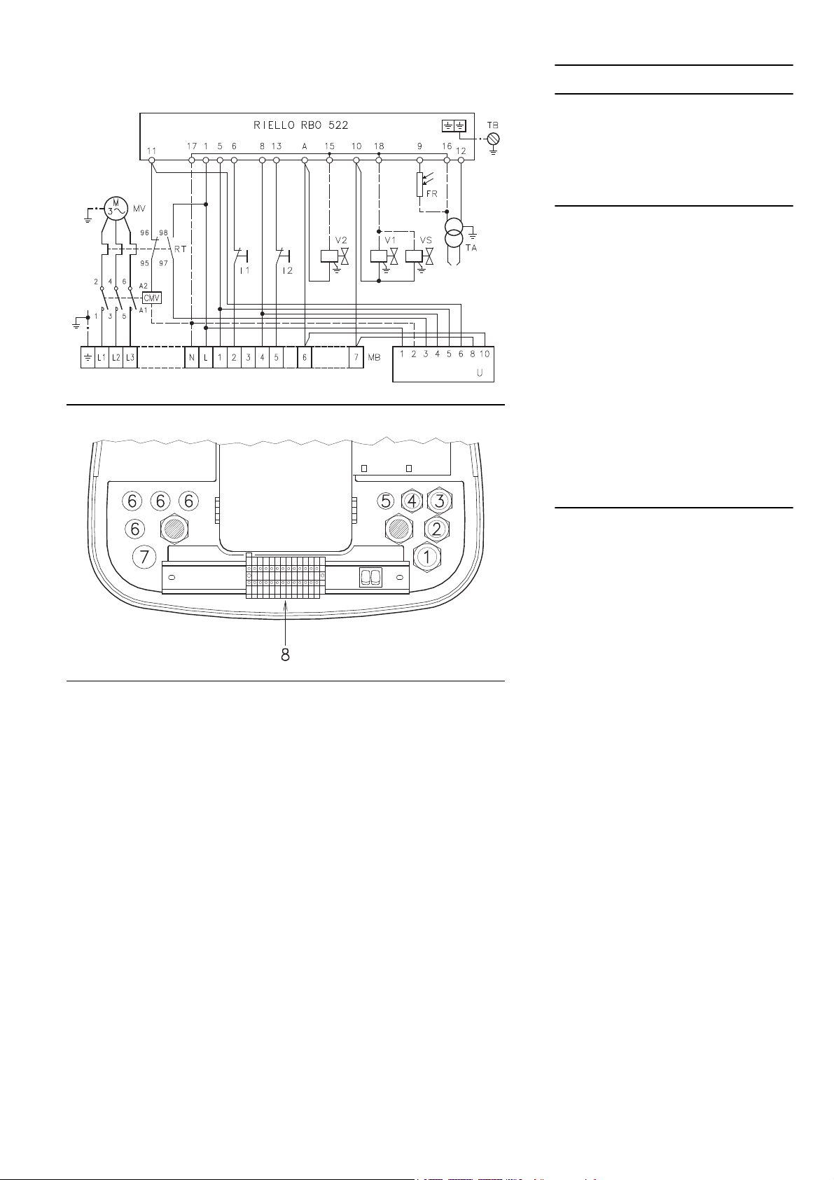
IMPIANTO ELETTRICO
IMPIANTO ELETTRICO eseguito in fabbrica
SCHEMA (A)
Bruciatore RL 190
¥ Il modello RL 190 lascia la fabbrica previsto
per alimentazione elettrica 400 V.
¥ Se l'alimentazione • 230 V, cambiare il colle-
gamento del motore (da stella a triangolo) e la
taratura del rel• termico.
Legenda schema (A) - (B)
CMV - Contattore motore
RBO 522- Apparecchiatura elettrica
FR - Fotoresistenza
I1 - Interruttore: bruciatore acceso-spento
I2 - Interruttore: 1° - 2° stadio
MB - Morsettiera bruciatore
MV - Motore ventilatore
RT - Rel• termico
TA - Trasformatore d'accensione
TB - Terra bruciatore
U - STATUS
V1 - Elettrovalvola 1° stadio
V2 - Elettrovalvola 2° stadio
VS - Elettrovalvola di sicurezza
NOTA
In caso di necessitˆ di avere lo sblocco a
distanza collegare un pulsante (NA) fra il morsetto 4 e il neutro dellÕapparecchiatura (morsetti
15, 16, 17 e 18).
(B)
COLLEGAMENTI ELETTRICI
eseguiti dall'installatore
Usare cavi ßessibili secondo norma EN 60 335-1:
¥ se sotto guaina di PVC almeno tipo H05 VV-F
¥ se sotto guaina di gomma almeno tipo H05
RR-F.
Tutti i cavi da collegare alla morsettiera 8)(B) del
bruciatore vanno fatti passare dai passacavi.
L'utilizzo dei passacavi pu˜ avvenire in vari
modi; a scopo esempliÞcativo indichiamo il
modo seguente:
1- Pg 13,5 alimentazione trifase
2- Pg 11 alimentazione monofase
3- Pg 11 telecomando TL
4- Pg 9 telecomando TR
5- Pg 9 Predisposizione per bocchettone
6- Pg 11 Predisposizione per bocchettone
7- Pg 13,5 Predisposizione per bocchettone
16

ELEKTROANLAGE
ELECTRICAL SYSTEM
INSTALLATION ELECTRIQUE
ELEKTROANLAGE werkseitig ausgefŸhrt
SCHEMA (A)
Brenner RL 190
¥ Das Modell RL 190 wird werkseitig fŸr 400 V
Stromversorgung vorbereitet.
¥ Falls die Stromversorgung 230 V betrŠgt, den
Motoranschlu§ (Stern- oder Dreieckschaltung)
und die Einstellung des WŠrmerelais verŠndern.
ErlŠuterung Schema (A) - (B)
CMV - Motorkontaktgeber
RBO 522- SteuergerŠt
FR - Foto-Widerstand
I1 - Schalter: Brenner Òein - ausÓ
I2 - Schalter: Ò1. - 2. StufeÓ
MB - Klemmbrett Brenner
MV - GeblŠsemotor
RT - WŠrmerelais
TA - ZŸndtransformator
TB - Erdung
U - STATUS
V1 - Elektroventil 1. Stufe
V2 - Elektroventil 2. Stufe
VS - Sicherheits-Elektroventil
BEMERKUNG
Fernentriegelung: einen Druckschalter (NO)
zwischen Klemme 4 und Nulleiterklemme des
Feuerungsautomaten (Klemme 15, 16, 17 u. 18)
geschaltet benŸtzen.
ELEKTROANSCHL†SSE
vom Installateur auszufŸhren
GemŠ§ Norm EN 60 335-1 biegsame Kabel verwenden:
¥ falls unter PVC-Mantel den Typ HO5 VV-F ver-
wenden
¥ falls unter Gummimantel den Typ HO5 RR-F
verwenden.
Alle mit der Klemmenleiste 8)(B) des Brenners
zu verbindenden Kabel sind durch die entsprechenden KabeldurchgŠnge zu fŸhren.
Die KabeldurchgŠnge kšnnen auf verschiedene
Arten genutzt werden. Als Beispiel fŸhren wir
die folgenden Arten auf:
1- Pg 13,5 Dreiphasenspeisung
2- Pg 11 Einphasenspeisung
3- Pg 11 Fernbedienung TL
4- Pg 9 Fernbedienung TR
5- Pg 9 Vorbereitung fŸr Stutzen
6- Pg 11 Vorbereitung fŸr Stutzen
7- Pg 13,5 Vorbereitung fŸr Stutzen
ELECTRICAL SYSTEM as set up by the manufacturer
LAYOUT (A)
Burner RL 190
¥ Model RL 190 leaves the factory preset for 400
V power supply.
¥ If 230 V power supply is used, change the
motor connection from star to delta and
change the setting of the thermal cut-out as
well.
Key to Layout (A) - (B)
CMV - Motor contactor
RBO 522- Control box
FR - Photocell
I1 - Switch: burner on - off
I2 - Switch: 1st - 2nd stage
MB - Terminal strip
MV - Fan motor
RT - Thermal cut-out
TA - Ignition transformer
TB - Burner ground (earth) connection
U - STATUS
V1 - 1st stage solenoid valve
V2 - 2nd stage solenoid valve
VS - Safety solenoid valve
NOTE
For remote-reset, connect a push-button switch
(NO) between terminal 4 and neutral of the control box (terminals 15, 16, 17 and 18).
ELECTRICAL CONNECTIONS
set by installer
Use ßexible cables according to regulation EN
60 335-1:
¥ if in PVC boot, use at least HO5 VV-F
¥ if in rubber boot, use at least H05 RR-F.
All the cables to be connected to the burner terminal strip 8)(B) must be routed through the fairleads.
The fairleads can be used in various ways. One
example is given below:
1- Pg 13,5 Three-phase power supply
2- Pg 11 Single-phase power supply
3- Pg 11 Control device TL
4- Pg 9 Control device TR
5- Pg 9 Set up for faird lead
6- Pg 11 Set up for faird lead
7- Pg 13,5 Set up for faird lead
INSTALLATION ELECTRIQUE effectuŽe en
usine
SCHEMA (A)
Bržleur RL 190
¥ Le mod•le RL 190 quitte l'usine prŽvu pour
une alimentation Žlectrique ˆ 400 V.
¥ Si l'alimentation est ˆ 230 V, modiÞer le bran-
chement du moteur (d'Žtoile ˆ triangle) et le
rŽglage du relais thermique.
LŽgende schŽmas (A) - (B)
CMV - Contacteur moteur
RBO 522- Coffret de sŽcuritŽ
FR - PhotorŽsistance
I1 - Interrupteur: allumŽ - Žteint bržleur
I2 - Interrupteur: 1•re - 2•me allure
MB - Bornier bržleur
MV - Moteur ventilateur
RT - Relais thermique
TA - Transformateur d'allumage
TB - Terre bržleur
U - STATUS
V1 - Electrovanne 1•re allure
V2 - Electrovanne 2•me allure
VS - Electrovanne de sŽcuritŽ
NOTE
Pour avoir le dŽblocage ˆ distance brancher un
bouton (O) entre le borne 4 et le neutre du bo”te
de contr™le (bornes 15, 16, 17 et 18).
RACCORDEMENTS ELECTRIQUES
effectuŽ par l'installateur
Utiliser c‰bles ßexibles selon norme EN 60 335-1:
¥ si en gaine PVC, au moins type H05 VV-F
¥ si en gaine caoutchouc, au moins type H05
RR-F.
Tous les c‰bles ˆ brancher au porte-bornes
8)(B) du bržleur doivent passer par les passec‰bles.
On peut utiliser les passe-c‰bles de diffŽrentes
fa•ons: ˆ titre exemple, nous indiquons la fa•on
suivante:
1- Pg 13,5 Alimentation triphasŽe
2- Pg 11 Alimentation monophasŽe
3- Pg 11 TŽlŽcommande TL
4- Pg 9 TŽlŽcommande TR
5- Pg 9 PrŽvu pour presse-Žtoupe
6- Pg 11 PrŽvu pour presse-Žtoupe
7- Pg 13,5 PrŽvu pour presse-Žtoupe
17

(A)
RELé TERMICO
THERMORELAIS
THERMAL RELAY
RELAIS THERMIQUE
(B)
RL 190
230 V 400 V
F A T25 T25
mm
2
2,5 2,5
L
SCHEMA (A)
Collegamento elettrico RL 190
alimentazione trifase 230/400 V con neutro
Fusibili e sezione cavi schema (A), vedi tabella.
Legenda schemi (A)
IN - Interruttore elettrico per arresto manuale
bruciatore
MB - Morsettiera bruciatore
S - Segnalazione di blocco a distanza
TL - Telecomando di limite: ferma il bruciatore
quando la temperatura o la pressione in
caldaia raggiunge il valore prestabilito.
TR - Telecomando di regolazione: comanda
1°e 2° stadio di funzionamento.
Necessario solo nel funzionamento bista-
dio.
TS - Telecomando di sicurezza: interviene in
caso di TL guasto.
Attenzione: il bruciatore lascia la fabbrica predisposto per funzionamento bistadio e quindi
deve essere collegato il telecomando TR per il
comando della valvola V2 del gasolio.
Se si desidera, invece, che il bruciatore abbia un
funzionamento monostadio, inserire, in sosituzione del telecomando TR, un ponte tra i morsetti 10 e 11 della morsettiera.
SCHEMA (B)
Taratura rele' termico 16)(A)p.8
Serve ad evitare la bruciatura del motore per un
forte aumento dell'assorbimento dovuto alla
mancanza di una fase.
¥ Se il motore • alimentato a stella, 400 V, il cur-
sore va posizionato sul "MIN".
¥ Se • alimentato a triangolo, 230 V, il cursore va
posizionato sul "MAX".
Se la scala del rel• termico non comprende
l'assorbimento di targa del motore a 400 V, la
protezione • assicurata lo stesso.
NOTE
Il bruciatore RL 190 lascia la fabbrica previsto
per alimentazione elettrica 400 V. Se l'alimenta-
zione • 230 V, cambiare il collegamento del
motore (da stella a triangolo) e la taratura del
rel• termico.
Il bruciatore RL 190 • stato omologato per funzionamento intermittente. Ci˜ signiÞca che deve
fermarsi "per Norma" almeno 1 volta ogni 24 ore
per permettere all'apparecchiatura elettrica di
effettuare un controllo della propria efÞcienza
all'avviamento. Normalmente l'arresto del bruciatore viene assicurato dal telecomando della
caldaia.
Se cos“ non fosse • necessario applicare in
serie a IN un interruttore orario che provveda
all'arresto del bruciatore almeno 1 volta ogni 24
ore.
ATTENZIONE: Non invertire il neutro con la
fase nella linea di alimentazione elettrica.
18

SCHEMA (A)
Elektroanschlu§ RL 190
dreiphasige Speisung 230/400 V mit Nulleiter
Sicherungen und Kabelquerschnitt Schemata
(A), siehe Tabelle.
ZeichenerklŠrung Schemen (A)
IN - Schalter fŸr das manuelle Ausschalten des
Brenners
MB - Klemmenbrett Brenner
S - Stšrungs-Fernmeldung
TL - Regelung: schaltet den Brenner aus, wenn
die Temperatur oder der Kesseldruck den
festgelegten Wert erreichen.
TR - Regelung: steuert 1. und 2. Betriebsstufe.
Wird nur bei zweistuÞgem Betrieb benš-
tigt.
TS - Sicherheitsregelung: tritt bei Defekt an TL
in Aktion.
Vorsicht: Der Brenner wird werkseitig auf den
ZWEI-Stufen-Betrieb voreingestellt und mu§
also zur Steuerung des Heiz”lventils V2 an die
Fernsteuerung TR angeschlossen werden.
Wird dagegen ein EIN-Stufen-Betrieb
erwŸnscht, so ist anstelle der Fernsteuerung TR
eine BrŸcke zwischen Klemmen 10 und 11 des
Klemmbretts legen.
LAYOUT (A)
RL 190 electrical connection three-phase
230/400 V power supply with neutral phase
wire
Fuses and cables section layout (A), see table.
Key to wiring layouts (A)
IN - Manual burner stop switch
MB - Terminal strip
S - Remote lock-out signal
TL - Limit control device system: this shuts
down the burner when the boiler temperature or pressure exceeds the setpoint
value.
TR - High-low mode control device system: This
controls operating stages 1 and 2 and is
necessary only for two-stage operation.
TS - Safety control device system: this oper-
ates when TL is faulty.
Important: the burner is factory set for twostage operation and it must therefore be connected to the TR remove control device to command light oil valve V2.
Alternatively, if single stage operation is
required, instead of control device TR install a
jumper lead between terminal 11 and 12 of the
terminal strip.
SCHEMA (A)
Branchement Žlectrique RL 190
alimentation triphasŽe 230/400 V avec neutre
Fusibles et section c‰bles schŽma (A), voir tab.
LŽgende schŽmas (A)
IN - Interrupteur Žlectrique pour arr•t manuel
bržleur
MB - Bornier bržleur
S - Signalisation blocage bržleur ˆ distance
TL - TŽlŽcommande de limite: arr•te le bržleur
quand la tempŽrature ou la pression dans
la chaudi•re atteind la valeur ÞxŽe.
TR - TŽlŽcommande de rŽglage: commande
1•re et 2•me allure de fonctionnement.
NŽcessaire seulement dans le fonctionne-
ment ˆ deux allures.
TS - TŽlŽcommande de sŽcuritŽ: quand la tŽlŽ-
commande TL est en panne.
Attention: le bržleur quitte l'usine dŽjˆ prŽdisposŽ au fonctionnement ˆ 2 allures, et la tŽlŽcommande TR de commande de la vanne V2 de
Þoul doit •tre reliŽe.
Si l'on dŽsire par contre un fonctionnement ˆ 1
allure, remplacer la tŽlŽcommande TR par un
pontet entre les bornes 10 et 11 du porte-bornes.
SCHEMA (D)
Einstellung WŠrmerelais 16)(A)S.8
Dieses schŸtzt den Motor vor dem Durchbrennen wegen erhšhter Stromaufnahme infolge des
Ausfallens einer Phase.
¥ Wenn der Motor Ÿber eine Sternschaltung mit
400 V- Spannung gesteuert wird, mu§ der Zeiger auf "MIN"- Stellung positioniert werden.
¥ Bei Dreieck-Schaltung mit 230 V- Spannung,
mu§ der Zeiger auf "MAX" gestellt werden.
Obwohl die Skala des WŠrmerelais nicht die
Entnahmewerte vorsieht, die auf dem Typenschild des 400 V-Motors angegeben sind, wird
der Schutz trotzdem gewŠhrleistet.
VERMERKE
Der Brenner RL 190 wird werkseitig fŸr 400 V
Stromversorgung vorbereitet. Falls die Stromversorgung 230 V betrŠgt, den Motoranschlu§
von Stern- auf Dreieckschaltung und die Einstellung des WŠrmerelais verŠndern.
Die Brenner RL 190 ist fŸr intermittierenden
Betrieb baumustergeprŸft. Das bedeutet, da§
sie - laut Vorschrift - wenigstens einmal pro 24
Stunden ausgeschaltet werden mŸssen, damit
die elektrischen Einrichtungen auf ihre FunktionstŸchtigkeit geprŸft werden kšnnen. Der
Brennerstillstand erfolgt Ÿblicherweise Ÿber die
Fernsteuerung der Kesselanlage.
Sollte dies nicht der Fall sein, mu§ an IN ein
Zeitschalter reihengeschaltet werden, der einen
Brennerstillstand einmal alle 24 Stunden
gewŠhrleistet.
ACHTUNG: Den Nulleiter nicht mit dem Phasenleiter in der Leitung der Stromversorgung vertauschen.
LAYOUT (D)
Calibration of thermal cut-out 16)(A)p.8
This is required to avoid motor burn-out in the
event of a signiÞcant increase in power absorption caused by a missing phase.
¥ If the motor is star-powered, 400 V, the cursor
should be positioned on "MIN".
¥ If the motor is delta-powered, 230 V, the cursor
should be positioned on "MAX".
Even if the scale of the thermal cut-out does not
include rated motor absorption at 400 V, protection is still ensured in any case.
N.B.
Burner model RL 190 leaves the factory preset
for 400 V power supply. If 230 V power supply is
used, change the motor connection from star to
delta and change the setting of the thermal cutout.
The RL 190 burner has been type- approved for
intermittent operation. This means they should
compulsorily be stopped at least once every 24
hours to enable the control box to perform
checks of its own efÞciency at start-up. Burner
halts are normally provided for automatically by
the boiler load control system.
If this is not the case, a time switch should be Þtted in series to IN to provide for burner shutdown at least once every 24 hours.
WARNING: Do not invert the neutral with the
phase wire in the electricity supply line.
SCHEMA (D)
RŽglage relais thermique 16)(A)p.8
Sert ˆ Žviter que le moteur grille suite ˆ une
forte augmentation de l'absorption due ˆ
l'absence d'une phase.
¥ Si le moteur est alimentŽ en Žtoile, 400 V, le
curseur doit •tre placŽ sur "MIN".
¥ S'il est alimentŽ en triangle, 230 V, le curseur
doit •tre placŽ sur "MAX".
Si l'Žchelle du relais thermique ne comprend
pas l'absorption indiquŽe sur la plaque du
moteur ˆ 400 V, la protection est quand m•me
assurŽe.
NOTES
Le bržleur RL 190 quitte l'usine prŽvu pour l'alimentation Žlectrique ˆ 400 V. Si l'alimentation
est ˆ 230 V, changer la connexion du moteur
(d'Žtoile ˆ triangle) et le rŽglage du relais thermique.
Le bržleur 190 a ŽtŽ homologuŽs pour fonctionner de fa•on intermittente. Cela veut dire qu'ils
doivent s'arr•ter selon les normes au moins 1
fois toutes les 24 heures pour permettre au bo”tier d'effectuer un contr™le de son efÞcacitŽ au
moment du dŽmarrage. Normalement l'arr•t du
bržleur est assurŽ par le thermostat de la chaudi•re.
Si ce nÕest pas le cas, appliquer en sŽrie un
interrupteur horaire au IN un interrupteur horaire
qui commanderait l'arr•t du bržleur au moins 1
fois toutes les 24 heures.
ATTENTION: Dans la ligne d'alimentation
Žlectrique, ne pas inverser le neutre avec la
phase.
19

POMPA - PUMPE - PUMP - POMPE
SUNTEC J7 C
J7 C
A
B
C
D
E
F
G
H
kg/h
bar
bar
cSt
°C
bar
bar
mm
230
10 - 21
0,45
2,8 - 200
90
1,5
12
0,170
(A)
Bruciatore/Brenner/Burner/Bržleur
Spento/Aus/Off/Eteint
Acceso/Ein/On/AllumŽ
(B)
1 2
Stadio/Stufe/Stage/Allure
1°
2°
POMPA (A)
1 - Aspirazione G 1/2"
2 - Ritorno G 1/2"
3 - Attacco manometro G 1/8"
4 - Attacco vacuometro G 1/8"
5 - Regolatore di pressione
6 - Vite di by-pass
A - Portata min. a 12 bar di pressione
B - Campo di pressione in mandata
C - Depressione max in aspirazione
D - Campo di viscositˆ
E - Temperatura max. gasolio
F - Pressione max. in aspirazione e ritorno
G - Taratura pressione in fabbrica
H - Larghezza maglia Þltro
INNESCO POMPA
- Accertarsi, prima di mettere in funzione il
bruciatore, che il tubo di ritorno in cisterna
non abbia occlusioni. Un eventuale impedimento provocherebbe la rottura dell'organo
di tenuta posto sull'albero della pompa. (La
pompa lascia la fabbrica con il by-pass
chiuso).
- Perch• la pompa possa autoinnescarsi • indispensabile allentare la vite 3)(A) della pompa
per sÞatare l'aria contenuta nel tubo di aspirazione.
- Avviare il bruciatore chiudendo i telecomandi e
con l'interruttore 1)(A) in posizione "ACCESO".
La pompa deve girare nel senso della freccia
riportata sul coperchio.
- Quando il gasolio fuoriesce dalla vite 3) la
pompa • innescata. Fermare il bruciatore:
interruttore 1)(B) in posizione "SPENTO" ed
avvitare la vite 3).
Il tempo necessario per questa operazione
dipende dal diametro e dalla lunghezza della
tubazione aspirante. Se la pompa non si innesca al primo avviamento e il bruciatore va in
blocco, attendere circa 15 s, sbloccare e ripetere l'avviamento. E cos“ di seguito. Ogni 5-6
avviamenti, attendere per 2-3 minuti il raffreddamento del trasformatore.
Non illuminare la fotoresistenza per evitare il
blocco del bruciatore; il bruciatore bloccherˆ in
ogni caso dopo una decina di secondi dal suo
avviamento.
Attenzione: l'operazione suindicata • possibile
perch• la pompa lascia la fabbrica piena di combustibile. Se la pompa • stata svuotata, riempirla di combustibile dal tappo del vacuometro
prima di avviarla, altrimenti grippa.
Quando la lunghezza della tubazione aspirante
supera i 20-30 m, riempire il condotto con
pompa separata.
20

PUMPE (A)
1 - Ansaugen G 1/2"
2 - RŸcklauf G 1/2"
3 - Anschlu§ Manometer G 1/8"
4 - Anschlu§ Vakuummeter G 1/8"
5 - Druckregler
6 - By-pass Schraube
A - Min.-Durchsatz bei einem Druck von 12 bar
B - Ausla§-Druckbereich
C - Max.-Ansaugunterdruck
D - ViskositŠtsbereich
E - Max. Heizšltemperatur
F - Max. Ansaug- und RŸcklaufdruck
G - Werkseitige Druckeinstellung
H - Filtermaschenweite
EINSCHALTEN DER PUMPE
- Bevor Sie den Brenner in Betrieb nehmen,
vergewissern Sie sich, ob die RŸcklaußeitung zum Tank frei ist. Eventuelle Hindernisse wŸrden zur BeschŠdigung des
Dichtungsorgans an der Pumpenwelle fŸhren. (Die Pumpe wird mit verschlossenem
Bypass ausgeliefert).
- Damit die Pumpe selbst einschalten kann,
muss die Schraube 3)(A) der Pumpe unbedingt gelockert werden, so dass der Ansaugschlauch entlŸftet werden kann.
- Den Brenner durch Schlie§en der Fernsteuerungen und mit Schalter 1)(B), auf "EIN" starten. Der Pumpendrehsinn mu§ der
Pßeilangabe auf dem Deckel entsprechen.
- Die Pumpe ist gefŸllt, wenn aus der Schraube
3) Heizšl heraustritt. Den Brenner stoppen:
Schalter 1)(C), auf "AUS" und die Schraube 3)
aufschrauben.
Die fŸr diesen Vorgang benštigte Zeit hŠngt vom
Durchmesser und der LŠnge der Ansaugleitung
ab. Falls sich die Pumpe nicht beim ersten
Anfahren einschaltet und der Brenner in Stšrabschaltung fŠhrt, 15. Sek. warten, entriegeln und
das Anfahren wiederholen, und so fort. Nach 5
bis 6 AnfahrvorgŠngen ungefŠhr 2-3 Minuten
auf die AbkŸhlung des Transformators warten.
Den Foto-Widerstand nicht beleuchten, um die
Stšrabschaltung des Brenners zu vermeiden.
Der Brenner fŠhrt in etwa 10 Sek. nach dem
Anfahren ohnehin in Stšrabschaltung.
Achtung: Dieser Vorgang ist mšglich, weil die
Pumpe werkseitig mit Heizšl gefŸllt wird; falls
die Pumpe geleert wurde, mu§ sie vor dem
Anfahren Ÿber den Stopfen des Vakuummeters
mit Brennstoff gefŸllt werden, weil sie festfri§t.
Falls die LŠnge der Ansaugleitungen 20-30 m
Ÿberschreitet, die Leitung mit einer anderen
Pumpe fŸllen.
PUMP (A)
1 - Suction G 1/2"
2 - Return G 1/2"
3 - Pressure gauge attachment G 1/8"
4 - Vacuum meter attachment G 1/8"
5 - Pressure adjustment screw
6 - By-pass screw
A - Min. delivery rate at 12 bar pressure
B - Delivery pressure range
C - Max. suction depression
D - Viscosity range
E - Max light oil temperature
F - Max. suction and return pressure
G - Pressure calibration in the factory
H - Filter mesh width
PUMP PRIMING
- Before starting the burner, make sure that
the tank return line is not clogged.
Obstructions in the line could cause the
sealing organ located on the pump shaft to
break. (The pump leaves the factory with the
by-pass closed).
- In order for self-priming to take place, the
screw 3)(A) of the pump must be loosened to
bleed off the air contained in the suction line.
- Start the burner by closing the control devices
with switch 1)(B) in the "ON" position. The
pump must rotate in the direction of the arrow
marked on the cover.
- The pump can be considered primed when the
light oil starts coming out of the screw 3). Stop
the burner: switch 1)(C) set to "OFF" and
tighten the screw 3).
The time required for this operation depends
upon the diameter and length of the suction tubing. If the pump fails to prime at the Þrst starting
of the burner and the burner locks out, wait
approx. 15 seconds, reset the burner, and then
repeat the starting operation as often as
required. After 5 or 6 starting operations allow 2
or 3 minutes for the transformer to cool.
Do not illuminate the photocell or the burner will
lock out; the burner should lock out anyway
about 10 seconds after it starts.
Important: the a.m. operation is possible
because the pump is already full of fuel when it
leaves the factory. If the pump has been
drained, Þll it with fuel through the opening on
the vacuum meter prior to starting; otherwise,
the pump will seize. Whenever the length of the
suction piping exceeds 20-30 meters, the supply
line must be Þlled using a separate pump.
POMPE (A)
1 - Aspiration G 1/2"
2 - Retour G 1/2"
3 - Raccord manom•tre G 1/8"
4 - Raccord vacuom•tre G 1/8"
5 - Vis rŽglage pression
6 - Vis by-pass
A - DŽbit min. ˆ 12 bar de pression
B - Plage de pression en refoulement
C - DŽpression max. en aspiration
D - Plage de viscositŽ
E - TempŽrature max. Þoul
F - Pression max. en aspiration et retour
G - RŽglage pression en usine
H - Largeur maille Þltre
AMOR‚AGE POMPE
- Avant de mettre le bržleur en marche,
s'assurer que le tuyau de retour dans la
cuve ne soit pas bouchŽ. Un obstacle Žventuel provoquerait la rupture de l'organe
d'ŽtanchŽitŽ situŽ sur l'arbre de la pompe.
(La pompe quitte lÕusine avec le by-pass
fermŽ).
- Pour que la pompe puisse s'auto-amorcer, il
est indispensable de desserrer la vis 3)(A) de
la pompe pour purger l'air contenu dans le
tuyau d'aspiration.
- Faire dŽmarrer le bržleur en fermant les tŽlŽcommandes et en pla•ant l'interrupteur 1)(B)
sur la position "ALLUME". La pompe doit tourner dans le sens indiquŽ par la ß•che dessinŽe sur le couvercle.
- Lorsque le Þoul dŽborde de la vis 3), la pompe
est amorcŽe. Refermer le bržleur: interrupteur
1)(C) sur "ETEINT" et serrer la vis 3).
Le temps nŽcessaire ˆ cette opŽration dŽpend
du diam•tre et de la longueur du tuyau d'aspiration. Si la pompe ne s'amorce pas au premier
dŽmarrage et si le bržleur se bloque, attendre
environ 15 s, dŽbloquer et rŽpŽter le dŽmarrage.
Et ainsi de suite. Tous les 5-6 dŽmarrages,
attendre pendant 2-3 minutes le refroidissement
du transformateur.
Ne pas Žclairer la photorŽsistance aÞn d'Žviter
le blocage du bržleur: celui-ci se bloque de toutes fa•ons une dizaine de secondes apr•s son
dŽmarrage.
Attention: l'opŽration ci-dessus est possible
parce que la pompe quitte l'usine pleine de combustible. Si la pompe a ŽtŽ vidŽe, la remplir de
combustible par le bouchon du vacuom•tre
avant de la mettre en marche pour Žviter les
grippages.
Quand la longueur du tuyau d'aspiration
dŽpasse les 20-30 m, remplir le tuyau avec une
pompe sŽparŽe.
21

(A)
Bruciatore/Brenner/Burner/Bržleur
Spento/Aus/Off/Eteint
Acceso/Ein/On/AllumŽ
(B)
1 2
Stadio/Stufe/Stage/Allure
1°
2°
REGOLAZIONE BRUCIATORE
ACCENSIONE
Mettere l'interruttore 1)(B) in posizione
"ACCESO".
Alla prima accensione, all'atto del passaggio dal
1° al 2° stadio, si ha un momentaneo abbassamento della pressione del combustibile conseguente al riempimento della tubazione del 2°
ugello. Questo abbassamento pu˜ provocare lo
spegnimento del bruciatore, talvolta accompagnato da pulsazioni.
Una volta effettuate le regolazioni descritte qui
di seguito, l'accensione del bruciatore deve
generare un rumore pari al funzionamento. Se si
avvertono una o pi• pulsazioni o un ritardo
d'accensione rispetto all'apertura della elettrovalvola del gasolio, vedere i suggerimenti indicati a p. 30: cause 34 ¸ 39.
FUNZIONAMENTO
Per ottenere una regolazione ottimale del bruciatore • necessario effettuare l'analisi dei gas
di scarico della combustione all'uscita della caldaia ed intervenire sui punti che seguono.
¥ Ugelli di 1° e 2° stadio
Vedere informazioni riportate a pag 12.
¥ Testa di combustione
La regolazione della testa giˆ effettuata non
necessita di modiÞche se non viene cambiata la
portata del bruciatore in 2° stadio.
¥ Pressione pompa
12 bar
: • la pressione regolata in fabbrica e in
genere va bene. Pu˜ essere necessario portarla
a:
per ridurre la portata del combustibile. E'
10 bar
possibile solo se la temperatura ambiente
rimane sopra 0 °C. Mai scendere sotto i 10 bar:
il martinetto potrebbe aprirsi con difÞcoltˆ;
14 bar per aumentare la portata del combustibile o per avere accensioni sicure anche a temperature inferiori a 0 °C.
Per variare la pressione della pompa agire
sulla vite 5)(A)p. 20.
¥ Serranda ventilatore - 1° stadio
Mantenere il bruciatore funzionante in 1° stadio
mettendo l'interruttore 2)(B) in posizione 1° stadio. L'apertura delle serrande 6)(A) va proporzionata all'ugello scelto: l'indice 8)(A) deve
trovarsi in corrispondenza della tacca indicata
sul settore graduato 7)(A). La regolazione si
ottiene ruotando l'esagono 2)(A):
- verso destra (segno -) l'apertura diminuisce;
- verso sinistra (segno +) l'apertura aumenta.
¥ Serranda ventilatore - 2° stadio
Mettere l'interruttore 2)(B) in posizione 2° stadio
e regolare la serranda 6)(A) agendo sull'esagono 4)(A), dopo aver allentato la ghiera 3)(A).
NOTA: per facilitare la regolazione degli esagoni
2) e 4)(A), servirsi della chiave esagona da 3
mm 5)(A).
22

BRENNEREINSTELLUNG
Z†NDEN
Den Schalter 1)(B) auf "EIN" stellen.
Beim ersten ZŸnden entsteht beim †bergang
von der 1. zur 2. Stufe ein momentaner Abfall
des Brennstoffdrucks, der durch die FŸllung der
Leitungen der 2. DŸse verursacht wird. Dieser
Abfall kann das Ausgehen des Brenners verursachen, das manchmal von Pulsationen begleitet wird.
Nach Abschlu§ der im nachhinein beschriebenen Einstellungen, mu§ das ZŸnden des Brenners ein dem Betrieb entsprechendes GerŠusch
erzeugen. Es treten eine oder mehrere Pulsationen oder eine Verzšgerung der ZŸndung im Vergleich zur …ffnung des Heizšl-Elektroventils auf;
beachten Sie hierzu die Hinweise auf Seite 31:
Ursachen 34 ¸ 39.
FUNKTION
FŸr die optimale Einstellung des Brenners sollten die Verbrennungsabgase am Kesselausgang analysiert und an den folgenden Punkten
eingegriffen werden.
¥ DŸsen der 1. und 2. Stufe
Die Informationen der Seite 12 beachten.
¥ Flammkopf
Die bereits erfolgte Einstellung des Flammkopfes braucht nicht nachjustiert zu werden, soweit
keine DurchsatzŠnderung des Brenners in der
2. Stufe erfolgt.
¥ Pumpendruck
12 bar
: ist der werkseitig eingestellte Druck, der
im allgemeinen ausreichend ist. Es kann allerdings erforderlich werden, diesen zu verŠndern,
und zwar auf:
10 bar
um den Durchsatz des Brennstoffs zu
vermindern. Dies ist nur dann mšglich, wenn die
Raumtemperatur nicht unter 0°C absinkt. Die 10
bar dŸrfen auf keinen Fall unterschritten werden,
weil der Zylinder sich sonst nur schwer šffnen
kšnnte;
14 bar
um den Durchsatz des Brennstoffs zu
erhšhen oder um auch bei Temperaturen unter
0°C sicheres ZŸnden zu gewŠhrleisten.
Der Pumpendruck wird durch Verstellen der
Schraube 5)(A)S. 20 verŠndert.
¥ Luftklappe - 1. Stufe
Halten Sie den Brenner in der 1. Stufe, indem
Sie den Schalter 2)(B) auf Position 1. Stufe stellen. Die …ffnung der Luftklappe 6)(A) ist auf die
gewŠhlte DŸse abzustimmen: die Marke 8)(A)
mu§ mit der Kerbe auf dem Skalensegment
7)(A) Ÿbereinstimmen. Die Einstellung durch
Verdrehen des Sechskantes 2)(A) vornehmen:
- nach rechts (Zeichen -) kleinere …ffnung;
- nach links (Zeichen +) grš§ere …ffnung.
¥ Luftklappe - 2. Stufe
Den Schalter 2)(B) in Position 2. Stufe bringen
und der Luftklappe 6)(A) Ÿber den Sechskant
4)(A) nach Lockern von Nutmutter 3)(A) einstellen.
MERKE: zwecks leichterer Verstellung der
Sechskante 2) und 4)(A) den 3 mm SechskantschlŸssel 5)(A) verwenden.
BURNER CALIBRATION
FIRING
Set switch 1)(B) to "ON".
During the Þrst Þring, during the passage from
the 1st to the 2nd stage, there is a momentary
lowering of the fuel pressure caused by the Þlling of the 2nd stage nozzle tubing. This lowering
of the fuel pressure can cause the burner to
lock-out and can sometimes give rise to pulsations.
Once the following adjustments have been
made, the Þring of the burner must generate a
noise similar to the noise generated during
operation. If one or more pulsations or a delay in
Þring in respect to the opening of the light oil
solenoid valve occur, see the suggestions provided on p. 32: causes 34 to 39.
OPERATION
The optimum calibration of the burner requires
an analysis of the ßue gases at the boiler outlet
and interventions on the following points.
¥ 1st and 2nd stage nozzles
See the information listed on page 12.
¥ Combustion head
The adjustment of the combustion head already
carried out need not be altered unless the 2nd
stage delivery of the burner is changed.
¥ Pump pressure
12 bar
: This is the pressure calibrated in the factory which is usually sufÞcient for most purposes. Sometimes, this pressure must be
adjusted to:
10 bar
in order to reduce fuel delivery. This
adjustment is possible only if the surrounding
temperature remains above 0°C. Never calibrate
to pressures below 10 bar, at which pressures
the cylinders may have difÞculty in opening;
14 bar
in order to increase fuel delivery or to
ensure Þrings even at temperatures of less than
0°C.
In order to adjust pump pressure, use the screw
5)(A)p. 20.
¥ 1st stage fan air gate valve
Keep the burner operating at 1st stage by setting the switch 2)(B) to the 1st stage position.
Opening of the air gate valves 6)(A) must be
adjusted in proportion to the selected nozzle:
the index 8)(A) must be aligned with the notch
indicated on the graduated sector 7)(A). This
adjustment is achieved by turning the hex element 2)(A):
- towards the right direction (- sign) the opening
is reduced;
- towards the left direction (+ sign) the opening
increases.
¥ 2nd stage fan air gate valve
Set switch 2)(B) to the 2nd stage position and
adjust the air gate valve 6)(A) by turning the hex
element 4)(A), after having loosened the ring nut
3)(A).
NOTE: in order to facilitate adjustment of hex
elements 2) and 4)(A), use a 3 mm Allen key
5)(A).
REGLAGE BRULEUR
ALLUMAGE
Mettre l'interrupteur 1)(B) sur la position
"ALLUME".
Au premier allumage ou au moment du passage
de la 1•re ˆ la 2•me allure, on a une baisse
momentanŽe de la pression du combustible, liŽe
au remplissage du conduit du 2•me gicleur.
Cette baisse peut provoquer l'extinction du bržleur, accompagnŽe parfois d'ˆ-coups.
Une fois effectuŽs les rŽglages dŽcrits ci-dessous, l'allumage du bržleur doit produire un bruit
semblable au bruit de fonctionnement. Si on
entend un ou plusieurs ˆ-coups ou un retard
d'allumage par rapport ˆ l'ouverture de l'Žlectrovanne de Þoul, voir les conseils donnŽs p. 33:
causes 34 ¸ 39.
FONCTIONNEMENT
Pour obtenir un rŽglage optimal du bržleur, il
faut effectuer l'analyse des gaz d'Žchappement
de la combustion ˆ la sortie de la chaudi•re et
intervenir sur les points suivants.
¥ Gicleurs de 1•re et 2•me allure
Voir informations donnŽes ˆ la page 12.
¥ T•te de combustion
Le rŽglage de la t•te dŽjˆ effectuŽ ne doit pas
•tre modiÞŽ si le dŽbit du bržleur en 2•me allure
n'est pas modiÞŽ.
¥ Pression pompe
12 bar
: c'est la pression rŽglŽe en usine et qui
convient gŽnŽralement. On peut avoir besoin de
la porter ˆ:
10 bar
pour rŽduire le dŽbit de combustible.
C'est possible seulement si la tempŽrature
ambiante reste supŽrieure ˆ 0°C. Ne jamais
descendre au-dessous de 10 bar: le vŽrin pourrait s'ouvrir avec difÞcultŽ;
14 bar
pour augmenter le dŽbit de combustible
ou pour avoir des allumages sžrs m•me ˆ des
tempŽratures infŽrieures ˆ 0 °C.
Pour modiÞer la pression de la pompe, agir sur
la vis 5)(A)p. 20.
¥ Volet ventilateur - 1•re allure
Maintenir le bržleur en mode de fonctionnement
ˆ 1•re allure en pla•ant l'interrupteur 2)(B) en
position 1•re allure. L'ouverture du volet 6)(A)
doit •tre proportionnŽe au gicleur choisi: le
rep•re 8)(A) doit correspondre ˆ l'encoche 2)(A)
indiquŽe sur le secteur graduŽ 7)(A). Le rŽglage
se fait par rotation de l'hexagone 2)(A):
- vers la droite (signe -) l'ouverture diminue;
- vers la gauche (signe +) l'ouverture augmente.
¥ Volet ventilateur - 2•me allure
Mettre l'interrupteur 2)(B) en position 2•me
allure et rŽgler le volet 6)(A) en agissant sur
l'hexagone 4)(A), apr•s avoir rel‰chŽ la bague
3)(A).
NOTE: pour faciliter le rŽglage des hexagones
2) et 4)(A), utiliser une clŽ hexagonale de 3 mm
5)(A).
23

(A)
FUNZIONAMENTO BRUCIATORE
AVVIAMENTO BRUCIATORE (A) - (B)
Fasi di avviamento con tempi progressivi in
secondi:
¥ 0 s :
Chiusura telecomando TL.
Avvio motore e inserimento trasformatore
dÕaccensione.
La pompa 3) aspira il combustibile dalla
cisterna attraverso il condotto 1) ed il Þltro 2) e
lo spinge sotto pressione in mandata. Il
pistone 4) si solleva ed il combustibile ritorna
in cisterna dai condotti 5)-7). La vite 6) chiude
il by-pass verso l'aspirazione e le elettrovalvole
8)-11)-16), diseccitate, chiudono la via verso
gli ugelli.
Il martinetto 15), pistone A, apre la serranda
aria: preventilazione con la portata dÕaria del
1° stadio.
¥ 20 ¸ 28 s :
Si aprono le elettrovalvole 16) e 8); il combustibile passa nel condotto 9), attraversa il Þltro
10), esce polverizzato dall'ugello e, a contatto
con la scintilla, si accende: Þamma 1° stadio.
¥ 5 s dopo lÕaccensione:
Si spegne il trasformatore di accensione.
Se il telecomando TR • chiuso o • sosituito da
un ponte, lÕelettrovalvola 11) di 2° stadio, eccitata, apre due vie: una verso il condotto 12), il
Þltro 13) e lÕugello di 2° stadio, e una verso il
martinetto 15), pistone B, che apre la serranda
del ventilatore in 2° stadio.
Termina il ciclo di avviamento.
FUNZIONAMENTO A REGIME
Impanto dotato di un telecomando TR
Terminato il ciclo di avviamento, il comando
dellÕelettrovalvola di 2° stadio passa al telecomando TR che controlla la pressione o la temperatura in caldaia.
¥ Quando la temperatura o la pressione
aumenta Þno all'apertura di TR, l'elettrovalvola
11) si chiude ed il bruciatore passa dal 2° a 1°
stadio di funzionamento.
¥ Quando la temperatura o la pressione diminui-
sce Þno alla chiusura di TR, l'elettrovalvola 11)
si apre ed il bruciatore passa dal 1° al 2° stadio di funzionamento.
E cos“ via.
¥ LÕ arresto del bruciatore avviene quando la
richiesta di calore • minore di quella fornita dal
bruciatore in 1° stadio. Il telecomando TL si
apre, le elettrovalvole 8)-16) si chiudono, la
Þamma si spegne repentinamente. La serranda del ventilatore si chiude completamente.
Impianto privo di TR, sostituito da un ponte
L'avviamento del bruciatore avviene come nel
caso precedente. Successivamente, se la temperatura, o la pressione, aumenta Þno all'apertura di TL, il bruciatore si spegne (tratto A-A nel
diagramma).
All'atto della diseccitazione della elettrovalvola
11), il combustibile contenuto nel martinetto 15),
pistone B, si scarica attraverso lÕugello.
MANCATA ACCENSIONE
Se il bruciatore non si accende si ha il blocco
del bruciatore entro 5 s dall'apertura della valvola di 1° stadio e 25 ¸ 33 s dopo la chiusura di
TL. La spia dell'apparecchiatura elettrica si
accende.
SPEGNIMENTO DEL BRUCIATORE IN FUNZIONAMENTO
Se la Þamma si spegne in funzionamento il bruciatore si disinserisce entro 1 s ed effettua un
tentativo di riavviamento con ripetizione del ciclo
di partenza.
(B)
24

BRENNERBETRIEB
ANFAHREN DES BRENNERS (A) - (B)
Startphasen mit progressiven Zeitangaben in
Sekunden:
¥ 0 s :
Einschalten der TL-Fernsteuerung.
Anlassen des Motor und Einschalten des
ZŸndtransformators.
Die Pumpe 3) saugt den Brennstoff Ÿber die
Leitung 1) und den Filter 2) vom Tank an und
pumpt ihn unter Druck in den Ausla§. Der Kolben 4) geht hoch und der Brennstoff kehrt
Ÿber die Leitungen 5)-7) in den Tank zurŸck.
Die Schraube 6) schlie§t den Bypass gegen
die Ansaugleitung ab und die unerregten Elektroventile 8)-11) und 16) verschlie§en den
Weg zu den DŸsen.
Der Zylinder 15), Kolben A, šffnet die Luftklappe: VorbelŸftung mit dem Luftdurchßu§
der 1. Stufe.
¥ 20 ¸ 28 s :
Die Elektroventile 16) und 8) werden gešffnet.
Der Brennstoff gelangt in die Leitung 9), passiert den Filter 10), tritt zerstŠubt aus der DŸse
aus und entzŸndet sich beim Kontakt mit dem
Funken: Flamme 1. Stufe.
¥ 5 s nach der ZŸndung:
Der ZŸndtransformator schaltet sich aus.
Wenn die Fernsteuerung TR geschlossen ist
oder durch eine †berbrŸckung ersetzt wurde,
šffnet das erregt Elektroventil 11) der 2. Stufe
zwei Wege: einen zur Leitung 12), zum Filter
13) und der DŸse der 2. Stufe, und einen zum
Zylinder 15), Kolben B, die Luftklappe der 2.
Stufe šffnet.
Der Anfahrzyklus ist beendet.
DAUERBETRIEB
Anlage mit TR-Fernsteuerung
Nach dem Anfahrzyklus geht die Steuerung des
Elektroventils der 2. Stufe zur TR-Fernsteuerung
Ÿber, die Temperatur oder den Druck im Kessel
Ÿberwacht.
¥ Wenn die Temperatur oder der Druck bis zur
…ffnung von TR zunimmt, schlie§t das
Magnetventil 11) und der Brenner geht von der
2. zur 1. Funktionsstufe Ÿber.
¥ Wenn Temperatur oder Druck bis zum Ver-
schlu§ von TR abnimmt, šffnet das Magnetventil 11) und der Brenner geht von der 1. zur
2. Funktionsstufe Ÿber, und so weiter.
¥ Das Anhalten des Brenners erfolgt wenn der
Bedarf an WŠrme kleiner als die vom Brenner
in der 1. Stufe gelieferte Menge ist. Die TLFernsteuerung wird gešffnet, die Elektroventile
8)-16) verschlie§en sich, die Flamme verlšscht augenblicklich. Die Luftklappe schlie§t
sich vollstŠndig.
Anlage ohne TR, mit BrŸcke
Das Anfahren des Brenners erfolgt wie oben
beschrieben. Wenn in der Folge die Temperatur
oder der Druck bis zum …ffnen von TL zunimmt,
geht der Brenner aus (Linie A-A des Diagramms).
Beim Aberregen des Elektroventils 11) wird der
im Zylinder 15), Kolben B enthaltene Brennstoff durch die DŸse entladen.
MANGELNDE Z†NDUNG
Wenn der Brenner nicht zŸndet, erfolgt die Stšrabschaltung des Brenners innerhalb von 5 s ab
dem …ffnen des Elektroventils der 1. Stufe und
25 ¸ 33 s nach dem Verschlu§ des TL.
Die Kontrollampe des GerŠts leuchtet auf.
AUSGEHEN W€HREND DES BETRIEBS
Wenn die Flamme wŠhrend des Betriebs verlšscht, schaltet sich der Brenner innerhalb von 1
s aus und versucht erneut anzufahren, wobei
die Phase des Anfahrens wiederholt wird.
BURNER OPERATION
BURNER STARTING (A) - (B)
Starting phases with progressive time intervals
shown in seconds:
¥ 0 s :
Control device TL closes.
The motor starts and the ignition transformer
is connected.
The pump 3) sucks the fuel from the tank
through the piping 1) and the Þlter 2) and
pumps it under pressure to delivery. The piston
4) rises and the fuel returns to the tank
through the piping 5) - 7). The screw 6) closes
the by-pass heading towards suction and the
solenoid valves 8) - 11) - 16), de-energized,
close the passage to the nozzles.
The hydraulic cylinder 15), piston A, opens the
air gate valve: pre-purging begins with the 1st
stage air delivery.
¥ 20 ¸ 28 s :
Solenoid valves 8) and 16) open and the fuel
passes through the piping 9) and Þlter 10) and
is then sprayed out through the nozzle, igniting
when it comes into contact with the spark. This
is the 1st stage ßame.
¥ 5 s after Þring:
The ignition transformer switches off.
If the control device TR is closed or has been
replaced by a jumper wire, the 2nd stage solenoid valve 11), energized, opens two passages: one to piping 12), Þlter 13), and the 2nd
stage nozzle, and the other to the cylinder 15),
piston B, that opens the fan air gate valve in
the 2nd stage.
The starting cycle comes to an end.
STEADY STATE OPERATION
System equipped with one control device TR
Once the starting cycle has come to an end, the
command of the 2nd stage solenoid valve
passes on to the control device TR that controls
boiler temperature or pressure.
¥ When the temperature or the pressure
increases until the control device TR opens,
solenoid valve 11) closes, and the burner
passes from the 2nd to the 1st stage of operation.
¥ When the temperature or pressure decreases
until the control device TR closes, solenoid
valve 11) opens, and the burner passes from
the 1st to the 2nd stage of operation, and so
on.
¥ The burner stops when the demand for heat is
less than the amount of heat delivered by the
burner in the 1st stage. In this case, the control
device TL opens, and solenoid valves 8)-16)
close, the ßame immediately goes out. The
fan's air gate valve closes completely.
Systems not equipped with control device
TR (jumper wire installed)
The burner is Þred as described in the case
above. If the temperature or pressure increase
until control device TL opens, the burner shuts
down (Section A-A in the diagram).
When the solenoid valve 11) de-energizes, the
fuel contained in the cylinder 15), piston B, is
discharged through the nozzle.
FIRING FAILURE
If the burner does not Þre, it goes into lock-out
within 5 s of the opening of the 1st stage solenoid valve and 25 ¸ 33 s after the closing of control device TL. The control box pilot light will light
up.
UNDESIRED SHUTDOWN DURING OPERATION
If the ßame goes out during operation, the
burner shuts down automatically within 1 second and automatically attempts to start again by
repeating the starting cycle.
FONCTIONNEMENT BRULEUR
DEMARRAGE BRULEUR (A) - (B)
Phases de dŽmarrage avec temps progressifs
en sec.
¥ 0 s :
Fermeture tŽlŽcommande TL.
DŽmarrage moteur et insertion transformateur
d'allumage.
La pompe 3) aspire le combustible de la cuve
ˆ travers le conduit 1) et le Þltre 2) et le refoule
sous pression. Le piston 4) se soul•ve et le
combustible revient dans la cuve par les
tuyaux 5)-7). La vis 6) ferme le by-pass c™tŽ
aspiration et les Žlectrovannes 8)-11)-16),
dŽsexcitŽes, ferment la voie c™tŽ les gicleurs.
Le vŽrin 15), piston A, ouvre le volet d'air: prŽventilation avec le dŽbit d'air de la 1•re allure.
¥ 20 ¸ 28 s :
Les Žlectrovannes 8) et 16) s'ouvrent. Le combustible passe dans le tuyau 9), ˆ travers le Þltre 10), sort atomisŽ par le gicleur et au
contact de l'ˆtincelle, s'allume: ßamme 1•re
allure.
¥ 5 s apr•s l'allumage:
Le transformateur d'allumage s'Žteint.
Si la tŽlŽcommande TR est fermŽe ou est remplacŽe par un pont, l'Žlectrovanne 11) de
2•me allure, excitŽe, ouvre deux voies: une
vers le tuyau 12), le Þltre 13) et le gicleur de
2•me allure, et une vers le vŽrin 15), piston B,
qui ouvre le volet d'air ˆ la 2•me allure.
Le cycle de dŽmarrage se termine.
FONCTIONNEMENT DE REGIME
Installation munie d'une tŽlŽcommande TR
Une fois le cycle de dŽmarrage terminŽ, la commande de l'Žlectrovanne de 2•me allure passe
ˆ la tŽlŽcommande TR qui contr™le la tempŽrature ou la pression dans la chaudi•re.
¥ Quand la tempŽrature, ou la pression, aug-
mente jusqu'ˆ l'ouverture de TR, l'Žlectrovanne 11) se ferme et le bržleur passe de la
2•me ˆ la 1•re allure de fonctionnement.
¥ Quand la tempŽrature, ou la pression, dimi-
nue jusqu'ˆ la fermeture de TR, l'Žlectrovanne
11) s'ouvre et le bržleur passe de la 1•re ˆ la
2•me allure de fonctionnement.
Et ainsi de suite.
¥ LÕ arr•t du bržleur a lieu quand la demande de
chaleur est infŽrieure ˆ celle fournie par le bržleur ˆ la 1•re allure. La tŽlŽcommande TL
s'ouvre et les Žlectrovannes 8)-16) se ferment, la ßamme s'Žteint immŽdiatement. Le
volet du ventilateur se ferme compl•tement.
Installation sans TR, remplacŽe par un pontet
Le dŽmarrage du bržleur se fait comme dans le
cas prŽcŽdent. Par la suite, si la tempŽrature, ou
la pression, augmente jusqu'ˆ l'ouverture de TL,
le bržleur s'Žteint (segment A-A dans le diagramme).
Au moment de la dŽsexcitation de l'Žlectrovanne
11), le combustible contenu dans le vŽrin 15),
piston B, se dŽcharge par le gicleur.
ABSENCE D'ALLUMAGE
Si le bržleur ne s'allume pas, on a le blocage
dans un dŽlai de 5 s ˆ compter de l'ouverture de
l'Žlectrovanne de 1•re allure et de 25 ¸ 33 s
apr•s la fermeture de TL.
Le voyant du coffret de sŽcuritŽ s'allume.
EXTINCTION AU COURS DU FONCTIONNEMENT
Si la ßamme s'Žteint au cours du fonctionnement, le bržleur s'arr•te dans un dŽlai d'une sec
et effectue un essai de redŽmarrage avec rŽpŽtition du cycle de dŽpart.
25
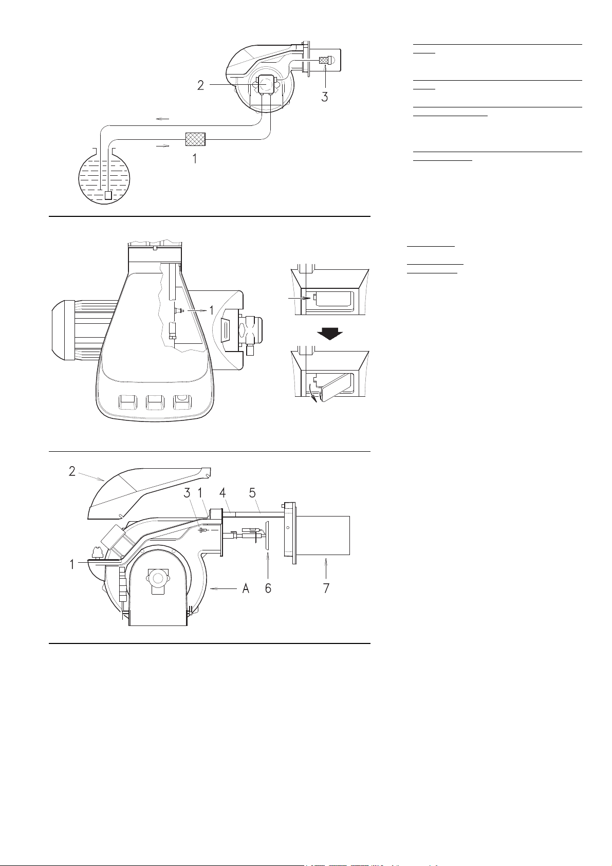
(A)
(B) (C)
(D)
CONTROLLI FINALI
are la fotoresistenza e chiudere i teleco-
¥ Oscur
mandi: il bruciatore deve avviarsi e poi fermarsi in blocco dopo circa 5 s dall'apertura
della valvola di 1° stadio.
¥ Illuminare la f
mandi: il bruciatore deve avviarsi e, dopo circa
10 s, fermarsi in blocco.
¥ Oscurare la fotoresistenza con bruciatore fun-
zionante in 2° stadio, deve avvenire in successione: spegnimento Þamma entro 1 s,
ventilazione per 20 ¸ 28 s, scintilla per circa 5
s, arresto del bruciatore in blocco.
¥ Aprire il telecomando TL e poi TS con brucia-
tore funzionante: il bruciatore deve fermarsi.
MANUTENZIONE
Combustione
Effettuare l'analisi dei gas di scarico della combustione. Gli scostamenti signiÞcativi rispetto al
precedente controllo indicheranno i punti dove
pi• attenta dovrˆ essere l'operazione di manutenzione.
Pompa
La pressione
12 bar.
La depressione deve essere inferiore a 0,45 bar.
umorositˆ non si deve avvertire.
La r
Nel caso di pressione instabile o pompa rumorrosa, scollegare il tubo ßessibile dal Þltro di linea
ed aspirare il combustibile da un serbatoio posto
vicino al bruciatore. Questo accorgimento consente di individuare se responsabile delle anomalie • il condotto di aspirazione o la pompa.
Se • la pompa, controllare che il suo Þltro non
sia sporco. Il vacuometro, infatti, essendo applicato a monte del Þltro non ne rileva lo stato di
sporcamento.
Se invece la causa delle anomalie sta nel condotto di aspirazione, controllare che non vi siano
Þltro di linea sporco o ingresso d'aria nel condotto.
Filtri (A)
Controllare i cestelli Þltranti:
¥ di linea 1) ¥ in pompa 2) ¥ all'ugello 3), pulirli o
sostituirli.
Se all'interno della pompa si notano ruggine o
altre impuritˆ, aspirare dal fondo della cisterna
con una pompa separata acqua ed altre impuritˆ eventualmente depositatesi.
Ventilatore
VeriÞcare che allÕinterno del ventilatore e sulle
pale della girante non vi sia accumulo di polvere: riduce la portata dÕaria e causa, conseguentemente, combustione inquinante.
Testa di combustione
VeriÞcare che tutte le parti della testa di combustione siano integre, non deformate dall'alta
temperatura, prive di impuritˆ provenienti
dall'ambiente e correttamente posizionate.
Ugelli
Evitare di pulire il foro degli ugelli.
Sostituire gli ugelli ogni 2-3 anni, o quando
necessario. Il cambio dell'ugello richiede un
controllo della combustione.
Fotoresistenza (B)
Pulire il vetro da eventuale polvere. Per estrarre
la fotoresistenza 1) tirarla verso l'esterno.
Visore Þamma (C)
Pulire il vetrino.
Tubi ßessibili
Controllare che il loro stato sia buono.
Cisterna
Ogni 5 anni, circa, aspirare l'acqua dal fondo
della cisterna con una pompa separata.
Caldaia
Pulire la caldaia secondo le istruzioni che
lÕaccompagnano in modo da poter riavere i dati
di combustione originari, specialmente:
pressione in camera di combustione e temperature fumi.
PER APRIRE IL BRUCIATORE (D)
- Togliere tensione
- Allentare le viti 1) e togliere il cofano 2)
- Svitare le viti 3)
- Montare le 2 prolunghe 4) date a corredo sulle
guide 5)
- Arretrare la parte A tenendola leggermente
sollevata per non danneggiare il disco 6) sul
boccaglio 7).
otoresistenza e chiudere i teleco-
in mandata deve essere stabile a
26

ENDKONTROLLEN
¥ Den F
¥ Den F
¥ Den F
¥ Die F
WARTUNG
Verbrennung Die Verbrennungsabgase sollten
analysiert werden. Bemerkenswerte VerŠnderungen der Werte im Vergleich zur vorherigen
Kontrolle zeigen jene Punkte auf, die mit besonderer Aufmerksamkeit gewartet werden sollten.
Pumpe
Der A
Der Unterdr
Das GerŠusch
bar sein.
Im Fall von Druckschwankungen oder
gerŠuschvoll arbeitender Pumpe den Schlauch
vom LinienÞlter abhŠngen und den Brennstoff
aus einem Tank in der NŠhe des Brenners
ansaugen. Mit diesem Trick kann festgestellt
werden, ob die Ansaugleitung oder die Pumpe
fŸr die Anomalie verantwortlich ist. Ist es die
Pumpe, kontrollieren Sie, ob ihr Filter verschmutzt ist. Da der Vakuummeter oberhalb des
Filters angebracht ist, kann er nŠmlich nicht
feststellen, ob dieser verschmutzt ist. Liegt die
Ursache der Stšrung indessen an der Ansaugleitung, kontrollieren Sie, ob der LinienÞlter verschmutzt ist oder Luft in die Leitung eintritt.
Filter (A) Die Filtersiebe kontrollieren:
¥ der Linie 1) ¥ in der Pumpe 2) ¥ an der DŸse
3), reinigen oder auswechseln.
Falls im Innern der Pumpe Rost oder andere
Verunreinigungen bemerkt werden, mit einer
separaten Pumpe Wasser und andere, eventuell
abgelagerte Verschmutzungen vom Tankboden
absaugen.
GeblŠse. PrŸfen Sie, ob im Innern des GeblŠses und auf seinen Schaufeln Staubablagerungen vorhanden sind: diese vermindern den
Luftdurchßu§ und verursachen folglich eine
umweltbelastende Verbrennung.
Flammkopf Kontrollieren Sie, ob alle Teile des
Flammkopfs ganz, nicht von der hohen Temperatur verformt, frei von Verunreinigungen aus
der Umwelt und korrekt ausgerichtet sind.
DŸsen Vermeiden Sie es die DŸsenbohrung zu
reinigen oder zu šffnen. Ersetzen Sie die DŸsen
alle 2-3 Jahre, oder wenn erforderlich. Das Auswechseln der DŸsen erfordert eine Kontrolle der
Verbrennung.
Lichtelektrische Foto-WiderstŠnde (B)
Glas von eventuellem Staub befreien. Den FotoWiderstand 1) krŠftig nach au§en ziehen.
Sichtfenster Flamme (C)
Das Glas bei Bedarf reinigen.
SchlŠuche Kontrollieren Sie, ob der Zustand
der SchlŠuche gut ist.
Tank UngefŠhr alle 5 Jahre mu§ das auf dem
Tankboden angesammelte Wasser mit einer
separaten Pumpe abgesaugt werden.
Kessel. Reinigen Sie den Kessel laut den mitgelieferten Anleitungen, so da§ die ursprŸnglichen Verbrennungsdaten erneut erhalten
werden, und zwar im besonderen: der Druck in
der Brennkammer und die Abgastemperatur.
Zuletzt den Zustand des Abzugs kontrollieren.
…FFNUNG DES BRENNERS (D)
- Spannung unterbrechen.
- Die Schrauben 1) lockern und die Verkleidung
- Schrauben 3) abdrehen.
- Die beiden beigepackten VerlŠngerungen 4)
- Teil A zurŸcksetzen, dabei leicht angehoben
oto-Widerstand verdunkeln und die
Fernsteuerungen schlie§en: der Brenner mu§
einschalten und ca. 5 s nach Ventilšffnung der
1. Stufe in Stšrabschaltung fahren.
oto-Widerstand beleuchten und die
Fernsteuerungen schlie§en: der Brenner mu§
einschalten und ca. 10 s danach in Stšrabschaltung fahren.
oto-Widerstand mit Brennerbetrieb auf
2. Stufe verdunkeln, es mu§ folgender Ablauf
stattÞnden: Erlšschen der Flamme in 1 s, ca.
20 ¸ 28 s BelŸftung, ca. 5 s ZŸndfunken, Stšr-
abschaltung des Brenners.
ernsteuerung TL und anschlie§end auch
TS bei funktionierendem Brenner šffnen: der
Brenner mu§ anhalten.
uslassdruck mu§ stabil auf 12 bar bleiben.
uck mu§ unter 0,45 bar liegen.
der Pumpe darf nicht wahrnehm-
2) abnehmen.
auf die FŸhrungen 5) einbauen.
halten, um die Scheibe 6) auf dem Flammrohr
7) nicht zu beschŠdigen.
FINAL CHECKS
¥ Obscure the photocell and s
trol devices: the burner should start and then
lock-out about 5 s after opening of the 1st
stage operation valve.
¥ Illuminate the photocell and s
trol devices: the burner should start and then
go into lock-out after about 10 s.
¥ Obscure the photocell while the burner is in
2nd stage operation, the following must occur
in sequence: ßame extinguished within 1 s,
pre-purging for about 20 ¸ 28 s, sparking for
about 5 s, burner goes into lock-out.
¥ Switch on control device TL followed by control
device TS while the burner is operating: the
burner should stop.
MAINTENANCE
Combustion. It is required an analysis of the
ßue gases at the boiler outlet. SigniÞcant differences with respect to the previous measurements indicate the points where more care
should be exercised during maintenance.
Pump
The pump deliv
12 bar.
The depression must be less than 0.45 bar.
usual noise must not be evident during pump
Un
operation.
If the pressure is found to be unstable or if the
pump runs noisily, the ßexible hose must be
detached from the line Þlter and the fuel must be
sucked from a tank located near the burner. This
measure permits the cause of the anomaly to be
traced to either the suction line or the pump.
If the pump is found to be responsible, check to
make sure that the Þlter is not dirty. The vacuum
meter is installed up-line from the Þlter and consequently will not indicate whether the Þlter is
clogged or not. Contrarily, if the problem lies in
the suction line, check to make sure that the Þlter is clean and that air is not entering the piping.
Filters (A)
Check the following Þlter boxes:
¥ on line 1) ¥ in pump 2) ¥ at nozzle 3), and
clean or replace as required.
If rust or other impurities are observed inside
the pump, use a separate pump to suck out any
water and other impurities that may have deposited on the bottom of the tank.
Fan. Check to make sure that no dust has accumulated inside the fan or on its blades, as this
condition will cause a reduction in the air ßow
rate and provoke polluting combustion.
Combustion head. Check to make sure that all
the parts of the combustion head are in good
condition, positioned correctly, free of all impurities, and that no deformation has been caused
by operation at high temperatures.
Nozzles. Do not clean the nozzle openings.
Replace the nozzles every 2-3 years or whenever necessary. Combustion must be checked
after the nozzles have been changed.
Photocell (B). Clean the glass cover from any
dust that may have accumulated. Photocell 1)
can be removed by pulling it outward forcefully.
Flame inspection window (C) Clean the glass.
Flexible hoses. Check to make sure that the
ßexible hoses are still in good condition.
Fuel tank. Every 5 years, or whenever necessary, suck out any water or other impurities
present on the bottom of the tank using a separate pump.
Boiler. Clean the boiler as indicated in its
accompanying instructions in order to maintain
all the original combustion characteristics intact,
especially the ßue gas temperature and combustion chamber pressure. Lastly, check the
condition of the ßue gas stack.
TO OPEN THE BURNER (D)
- Switch off the electrical power
- Loosen screws 1) and withdraw the cover 2)
- Unscrew screws 3)
- Fit the two extensions 4) supplied with the
burner onto the slide bars 5)
- Pull part A backward keeping it slightly raised
to avoid damaging the disk 6) on blast tube 7).
ery pressure must be stable at
witch off the con-
witch off the con-
CONTROLES FINAUX
¥ Obscurcir la photorŽsistance et f
tŽlŽcommandes: le bržleur doit dŽmarrer et se
bloquer 5 secondes environ apr•s l'ouverture
de la vanne de 1•re allure.
¥ Eclairer la photorŽsistance et f
commandes: le bržleur doit dŽmarrer et,
apr•s environ 10 secondes, se bloquer.
¥ Obscurcir la photorŽsistance bržleur f
nant en 2. allure, on doit avoir en sŽquence:
extinction de ßamme dans la seconde qui suit,
ventilation pendant 20 ¸ 28 secondes environ,
Žnticelle pendant 5 secondes environ et blocage du bržleur.
¥ Ouvr
ir d'abord la tŽlŽcommande TL et ensuite
la tŽlŽcommande TS, avec bržleur en fonctionnement: le bržleur doit s'arr•ter.
ENTRETIEN
Combustion
Effectuer l'analyse des gaz d'Žchappement de la
combustion. Les diffŽrences signiÞcatives par
rapport au contr™le prŽcŽdent indiqueront les
points o• l'opŽration d'entretien devra •tre plus
approfondie.
Pompe
La pression
bar.
La dŽpression
Le br
ble.
En cas de pression instable ou de pompe
bruyante, retirer le tuyau ßexible du Þltre de ligne
et aspirer le combustible d'un rŽservoir situŽ ˆ
proximitŽ du bržleur. Cette opŽration permet de
repŽrer si c'est le tuyau d'aspiration qui est responsable de l'anomalie ou bien la pompe.
Si c'est la pompe, contr™ler que son Þltre ne soit
pas sale. En effet, Žtant montŽ en amont du Þltre, le vacuom•tre ne dŽtecte pas l'Žtat
d'encrassement.
Au contraire, si la cause des anomalies est liŽe
au tuyau d'aspiration, contr™ler qu'il n'y ait pas
de Þltre de ligne encrassŽ ou de pŽnŽtration
d'air dans le tuyau.
Filtres (A)
Contr™ler les ŽlŽments Þltrants:
¥ de ligne 1) ¥ sur la pompe 2) ¥ au gicleur 3),
les nettoyer ou les remplacer.
A lÕintŽrieur du bržleur, si on remarque ˆ de la
rouille ou d'autres impuretŽs, aspirer lÕeau et les
impuretŽs qui ont pu se dŽposer au fond la cuve
avec une pompe sŽparŽe.
Ventilateur. VŽriÞer qu'il n'y ait pas de poussi•re accumulŽe ˆ l'intŽrieur du ventilateur et
sur les palettes du rotor: cette poussi•re rŽduit
le dŽbit d'air et produit par consŽquent une combustion polluante.
T•te de combustion Contr™ler que toutes les
parties de la t•te de combustion soient intactes,
ne soient pas dŽformŽes par la haute tempŽrature, nÕaient pas d'impuretŽs provenant du
milieu environnant et soient positionnŽes correctement.
Gicleurs Eviter de nettoyer le trou des gicleurs.
Changer les gicleurs tous les 2-3 ans, ou quand
cela s'av•re nŽcessaire. Le changement du
gicleur implique un contr™le de la combustion.
PhotorŽsistance (B) Eliminer Žventuellement
la poussi•re sur la vitre. Pour extraire la photorŽsistance 1) la tirer celle-Žnergiquement vers
l'extŽrieur.
Viseur ßamme (C) Nettoyer la vitre.
Tuyaux ßexibles Contr™ler qu'ils soient en bon
Žtat.
Cuve Tous les 5 ans environ, aspirer l'eau ou
les impuretŽs qui ont pu se dŽposer dans le
fond de la cuve, en utilisant une pompe sŽparŽe.
Chaudi•re. Nettoyer la chaudi•re selon les instructions fournies, de mani•re ˆ pouvoir retrouver les donnŽes de combustion originales, en
particulier: pression dans la chambre de combustion et tempŽrature fumŽes. Contr™ler, pour
Þnir, l'Žtat du conduit de cheminŽe.
POUR OUVRIR LE BRULEUR (D)
- Couper la tension
- Desserrer les vis 1) et extraire le coffret 2)
- DŽvisser les vis 3)
- Monter les 2 rallonges 4) fournies de sŽrie sur
les guides 5)
- Reculer la partie A en la soulevant lŽg•rement
pour ne pas ab”mer le disque 6) sur la buse 7).
en refoulement doit •tre stable ˆ 12
doit •tre infŽrieure ˆ 0,45 bar.
uit de la pompe ne doit pas •tre percepti-
ermer les
ermer les tŽlŽ-
onction-
27

STATUS
STATUS
LED lampeggiante
LED acceso
Tempo in secondi
La fase di avviamento • terminata
Led ßashing
Led illuminated
Time in seconds
Burner start cycle terminated
(A)
LED blinkend
LED leuchtet
Zeit in Sekunden
Anfahrphase abgeschlossen
Led clignotante
Led allumŽe
Temps en secondes
La phase de dŽmarrage est terminŽe
STATUS svolge tre funzioni:
1 - INDICA SUL VISORE V LE ORE DI FUN-
ZIONAMENTO ED IL NUMERO DI ACCENSIONI DEL BRUCIATORE
Ore di funzionamento totali
Premere il pulsante "h1".
Ore di funzionamento in 2° stadio
Premere il pulsante "h2".
Ore di funzionamento in 1° stadio (calcolate)
Ore totali - ore in 2° stadio.
Numero di accensioni
Premere il pulsante "count".
eramento ore di funzionamento e n° accen-
Azz
sioni
Premere contemporaneamente i tre pulsanti
"reset".
Memoria permanente
Le ore di funzionamento ed il n° accensioni
rimangono in memoria anche nel caso di interruzione elettrica.
2 - INDICA I TEMPI DELLA FASE DI AVVIA-
MENTO
L'accensione dei led avviene con la seguente
successione, vedi Þg. A:
CON TERMOSTATO TR CHIUSO:
1 - Bruciatore spento, termostato TL aperto
2 - Chiusura termostato TL
3 - Avvio motore:
inizia il conteggio in sec.
4 - Eccitazione valvola 1° stadio
5 - Eccitazione valvola 2° stadio
termina il conteggio in sec. nel visore V
6 - Dopo 10 sec. da 5 appare I I I I sul visore:
la fase di avviamento • terminata.
CON TERMOSTATO TR APERTO:
1 - Bruciatore spento, termostato TL aperto
2 - Chiusura termostato TL
3 - Avvio motore:
inizia il conteggio in sec. nel visore V
4 - Eccitazione valvola 1° stadio
7 - Dopo 30 sec. da 4:
termina il conteggio in sec. nel visore V
8 - Dopo 10 sec. da 7 appare I I I I sul visore: la
fase di avviamento • terminata.
I tempi in secondi che appaiono sul visore V
segnalano la successione delle varie fasi di
avviamento indicate a pag. 24.
3 - IN CASO DI GUASTO DEL BRUCIATORE,
SEGNALA IL MOMENTO IN CUI QUESTO
E' AVVENUTO
Sono possibili tre combinazioni di led accesi,
vedi Þg. (B).
Per le cause del guasto vedere i numeri tra
parentesi e, a pag. 30, il loro signiÞcato.
1 . . . . . . . . . . . (11 ¸ 12)
2 . . . . . . . . . . . (14 ¸ 33)
3 . . . . . . . . . . . (13)
nel visore V
28
SigniÞcato dei simboli:
=Tensione presente
=Blocco motore ventilatore (rosso)
=Blocco bruciatore (rosso)
=Funzionamento in 2° stadio
=Funzionamento in 1° stadio
=Carico raggiunto (Stand-by)

STATUS
STATUS
STATUS
STATUS fŸhrt drei Funktionen aus:
1 - ANZEIGE V MIT BETRIEBSSTUNDEN
UND ANZAHL DER ANFAHRVORG€NGE
DES BRENNERS
Gesamtbetr
Taste "h1" drŸcken.
Betriebsstunden auf 2. Stufe
Taste "h2" drŸcken.
(Berechnete) Betriebsstunden auf 1. Stufe.
Gesamtstunden - Stunden auf 2. Stufe.
AnfahrvorgŠnge
Taste "count" drŸcken.
Nullung Betr
Die drei "Reset"-Tasten gleichzeitig drŸcken.
Permanentspeicher
Die Betriebsstunden sowie die Anzahl der
AnfahrvorgŠnge bleiben auch im Fall eines
Stromabfalls permanent gespeichert.
2 - ZEIGT DIE ZEITEN DER STARTPHASE
Die LED leuchten in nachstehender Reihenfolge
auf, siehe Abb. A:
BEI GESCHLOSSENEM TR THERMOSTAT:
1 - Brenner ausgeschaltet, TL Thermostat
2 - Schlie§ung TL Thermostat
3 - Motorstart:
4 - Ventilerregung 1. Stufe
5 - Ventilerregung 2. Stufe
6 - 10 Sek. nach 5 erscheint I I I I auf der
BEI GEëFFNETEM TR THERMOSTAT:
1 - Brenner ausgeschaltet, TL Thermostat
2 - Schlie§ung TL Thermostat
3 - Motorstart:
4 - Ventilerregung 1. Stufe
7 - 30 Sek. nach 4:
8 - 10 Sek. nach 7 erscheint I I I I auf der
Die Zeitangaben in Sekunden auf der Anzeige V
verdeutlichen die Abfolge der einzelnen auf
Seite 25 angefŸhrten Startphasen.
3 - BEI GEST…RTEM BRENNER ZEIGT ES
Drei Kombinationen erleuchteter LED sind mšglich, s. Abb. (B).
FŸr die Stšrungsursachen die in Klammern stehenden Zahlen vergleichen, auf Seite 31 Þnden
Sie ihre Bedeutung.
1 . . . . . . . . . . . (11 ¸ 12)
2 . . . . . . . . . . . (14 ¸ 33)
3 . . . . . . . . . . . (13)
Bedeutung der Symbole:
iebsstunden
iebsstunden sowie AnfahrvorgŠnge
AN
gešffnet
ZŠhlung In Sek.
ZŠhlung In Sek. Auf Anzeige V endet
Anzeige: Startphase ist abgeschlossen.
gešffnet
ZŠhlung In Sek. Auf Anzeige V beginnt
ZŠhlung In Sek. Auf Anzeige V endet
Anzeige: Startphase ist abgeschlossen.
DEN ZEITPUNKT DER ST…RUNG AN
Auf Anzeige V beginnt
=Netzstrom ein
=Stšrabschaltung GeblŠsemotor (rot)
=Stšrabschaltung Brenner (rot)
=Betrieb auf 2. Stufe
=Betrieb auf 1. Stufe
=Leistung erreicht (Stand-by)
The STATUS unit has three functions:
1 - BURNER OPERATING HOURS AND THE
NUMBER OF FIRINGS ARE SHOWN ON
DISPLAY V
T
otal operating hours
Press button "h1".
2nd stage operating hours
Press button "h2".
1st stage operating hours
Total hours - 2nd stage operating hours.
Number of Þrings
Press button "count".
Resetting oper
Press the three "reset" buttons simultaneously.
Non-volatile memory
The operating hours and the number of Þrings
will remain in the memory even in the case of
electrical power failures.
2 - INDICATES THE TIMES RELATIVE TO THE
FIRING STAGE
The leds illuminate in the following sequence,
see Þg. A:
WITH CONTROL DEVICE TR CLOSED:
1 - Burner off, TL open
2 - Control device TL closed
3 - Motor start:
seconds count star
4 - 1st stage valve energized
5 - 2nd stage valve energized
seconds count stops on read-out V
6 - 10 seconds after stage 5 the code I I I I will
appear on the read-out: this indicates that
the starting phase is terminated.
WITH CONTROL DEVICE TR OPEN:
1 - Burner off, TL open
2 - Control device TL closed
3 - Motor start:
seconds count starts on read-out V
4 - 1st stage valve energized
7 - 30 seconds after stage 4:
seconds count stops on read-out V
8 - 10 seconds after stage 7 the code I I I I will
appear on the read-out: this indicates that
the starting phase is terminated.
The times, in seconds, shown on read-out V,
indicate the succession of the various starting
stages described on page 25.
3 - IN THE CASE OF BURNER MALFUNC-
TIONS, THE STATUS PANEL INDICATES
THE EXACT TIME AT WHICH THE FAULT
OCCURRED
There are 3 possible combinations of illuminated leds, see Þg. (B).
For the causes of the malfunction refer to the
numbers shown between brackets; see the legend on page 32 for interpretation of the numbers.
1. . . . . . . . . . . .(11 - 12)
2. . . . . . . . . . . .(14 ¸ 33)
3. . . . . . . . . . . .(13)
Key to symbols:
ating hours and number of Þrings
ts on read-out V
=Power present
=Fan motor blocked (red)
=Burner lock-out (red)
=2nd stage operation
=1st stage operation
=Load level reached (Stand-by)
STATUS accomplit trois fonctions:
1 - INDIQUE SUR LE VISEUR V LES HEURES
DE FONCTIONNEMENT ET LE NOMBRE
D'ALLUMAGES DU BRULEUR
Heures totales de f
Presser le B.P. "h1".
Heures de fonctionnement en 2•me allure
Presser le B.P. "h2".
Heures de fonctionnement en 1•re allure
Heures totales - Heures en 2•me allure.
Nombre d'allumages
Presser le B.P. "count".
R.A.Z heures de f
d'allumages.
Presser simultanŽment les trois B.P de "reset".
MŽmoire permanente
Les heures de fonctionnement et le nombre
d'allumages restent en mŽmoire m•me dans le
cas d'une interruption Žlectrique.
2 - INDIQUE LES TEMPS DE LA PHASE DE
DEMARRAGE
L'allumage des LED se fait dans la succession
suivante, voir Þg. A:
THERMOSTAT TR FERME:
1 - Bržleur Žteint, thermostat TL ouvert
2 - Fermeture thermostat TL
3 - DŽmarrage moteur:
ut de comptage en sec. dans le viseur V
dŽb
4 - Excitation vanne 1•re allure
5 - Excitation vanne 2•me allure:
Þn du comptage en sec. dans le viseur V
6 - 10 sec. aprŠs 5, I I I I est afÞchŽ sur le
viseur: la phase de dŽmarrage est terminŽe.
THERMOSTAT TR OUVERT:
1 - Bržleur Žteint, thermostat TL ouvert
2 - Fermeture thermostat TL
3 - DŽmarrage moteur:
dŽbut du comptage en sec. dans le viseur V
4 - Excitation vanne 1•re allure
7 - 30 sec. apr•s 4:
Þn du comptage en sec. dans le viseur V
8 - 10 sec. apr•s 7, I I I I apparait sur le viseur:
la phase de dŽmarrage est terminŽe.
Les temps en sec. qui apparaissent sur le viseur
V indiquent la succession des diffŽrentes phases de dŽmarrage indiquŽes page 25.
3 - EN CAS DE PANNE DU BRULEUR,
SIGNALE LE MOMENT EXACT D'INTER-
VENTION DE CETTE PANNE
3 combinaisons de LED allumŽes possibles, voir
Þg. (B).
Pour les causes de la panne voir les numŽros
entre parenth•ses et, page 33, leur signiÞcation.
1 . . . . . . . . . . . (11 - 12)
2 . . . . . . . . . . . (14 ¸ 33)
3 . . . . . . . . . . . (13)
SigniÞcation des symboles:
onctionnement
onctionnement et nombre
=Tension prŽsente
=Blocage moteur ventilateur (rouge)
=Blocage bržleur (rouge)
=Fonctionnement en 2•me allure
=Fonctionnement en 1•re allure
=Charge atteinte (Stand-by)
29

INCONVENIENTE CAUSA PROBABILE RIMEDIO CONSIGLIATO
Il bruciatore non si avvia 1 - Manca lÕenergia elettrica. . . . . . . . . . . . . . . . . . . . . . . . . . . Chiudere interruttori - controllare fusibili
Il bruciatore si avvia e poi si arresta in
blocco
Superata la preventilazione ed il tempo
di sicurezza il bruciatore va in blocco
senza apparizione di Þamma
La Þamma si accende regolarmente ma
il bruciatore va in blocco al termine del
tempo di sicurezza
Accensione con pulsazioni o con stacco
Þamma, accensione ritardata
Il bruciatore non passa in 2° stadio 40 - Telecomando TR non chiude . . . . . . . . . . . . . . . . . . . . . . . Regolarlo o sostituirlo
Il combustibile passa in 2° stadio e lÕaria
resta in 1° stadio.
Arresto del bruciatore al passaggio tra 1°
e 2° stadio o tra 2° e 1° stadio.
Il bruciatore ripete il ciclo di avviamento.
Alimentazione combustibile irregolare 48 - Capire se la causa sta nella pompa o . . . . . . . . . . . . . . . . Alimentare il bruciatore
Pompa arruginita internamente 49 - Acqua in cisterna . . . . . . . . . . . . . . . . . . . . . . . . . . . . . . . . Aspirarla dal fondo cisterna con una pompa
Pompa rumorosa, pressione pulsante 50 - Ingresso aria nella tubazione di aspirazione . . . . . . . . . . . Bloccare i raccordi
Pompa che si disinnesca dopo una sosta
prolungata
Pompa con perdita di gasolio 58 - Perdita dallÕorgano di tenuta. . . . . . . . . . . . . . . . . . . . . . . . Sostituire pompa
Fiamma fumosa- Bacharach scuro
- Bacharach giallo
Testa di combustione sporca 66 - Ugello o Þltro ugello sporco . . . . . . . . . . . . . . . . . . . . . . . . Sostituirlo
2 - Il telecomando di limite TL aperto. . . . . . . . . . . . . . . . . . . . Regolarlo o sostituirlo
3 - Il telecomando di sicurezza TS aperto . . . . . . . . . . . . . . . . Regolarlo o sostituirlo
4 - Blocco apparecchiatura . . . . . . . . . . . . . . . . . . . . . . . . . . . . . . . Sbloccare apparecchiatura (dopo 10 s dal blocco)
5 - Blocco motore. . . . . . . . . . . . . . . . . . . . . . . . . . . . . . . . . . . Sbloccare rel• termico
6 - Pompa bloccata . . . . . . . . . . . . . . . . . . . . . . . . . . . . . . . . . Sostituirla
7 - Collegamenti elettrici malfatti . . . . . . . . . . . . . . . . . . . . . . . Controllarli
8 - Apparecchiatura elettrica difettosa . . . . . . . . . . . . . . . . . . Sostituirla
9 - Teleruttore comando motore difettoso . . . . . . . . . . . . . . . . Sostituirlo
10 - Motore elettrico difettoso . . . . . . . . . . . . . . . . . . . . . . . . . . Sostituirlo
11 - Fotoresistenza in cortocircuito . . . . . . . . . . . . . . . . . . . . . . Sostituire fotoresistenza
12 - Luce estranea o simulazione di Þamma . . . . . . . . . . . . . . . Eliminare luce o sostituire apparecchiatura
13 - Alimentazione elettrica a due fasi. . . . . . . . . . . . . . . . . . . . Sbloccare il rel• termico
interviene il rel• termico al ritorno delle tre fasi
14 - Manca il combustibile in cisterna, o vi • acqua sul fondo. . Fare rifornimento o aspirare lÕacqua
15 - Regolazioni testa e serranda non adatte . . . . . . . . . . . . . . Regolarle, vedi pag. 12 e 22
16 - Elettrovalvole gasolio non aprono (1° stadio o sicurezza) . Controllare collegamenti, sostituire bobina
17 - Ugello 1° stadio otturato, sporco o deformato . . . . . . . . . . Sostituirlo
18 - Elettrodi dÕaccensione mal regolati, o sporchi . . . . . . . . . . Regolarli o pulirli
19 - Elettrodo a massa per isolante rotto. . . . . . . . . . . . . . . . . . Sostituirlo
20 - Cavo alta tensione difettoso o a massa . . . . . . . . . . . . . . . Sostituirlo
21 - Cavo alta tensione deformato da alta temperatura. . . . . . . Sostituirlo e proteggerlo
22 - Trasformatore dÕaccensione difettoso. . . . . . . . . . . . . . . . . Sostituirlo
23 - Collegamenti elettrici valvole o trasformatore mal fatti . . . . Controllarli
24 - Apparecchiatura elettrica difettosa . . . . . . . . . . . . . . . . . . Sostituirla
25 - Pompa disinnescata . . . . . . . . . . . . . . . . . . . . . . . . . . . . . . Innescarla e vedere Òpompa che si disinnescaÓ
26 - Giunto motore-pompa rotto . . . . . . . . . . . . . . . . . . . . . . . . Sostituirlo
27 - Aspirazione pompa collegata al tubo di ritorno. . . . . . . . . . Correggere collegamento
28 - Valvole a monte della pompa chiuse . . . . . . . . . . . . . . . . . Aprirle
29 - Filtri sporchi (di linea - in pompa -allÕugello) . . . . . . . . . . . . Pulirli
30 - Rotazione motore contraria . . . . . . . . . . . . . . . . . . . . . . . . Cambiare i collegamenti elettrici al motore
31 - Fotoresistenza o apparecchiatura diffettosa. . . . . . . . . . . . Sostituire fotoresistenza o apparecchiatura
32 - Fotoresistenza sporca . . . . . . . . . . . . . . . . . . . . . . . . . . . . Pulirla
33 - 1° stadio del martinetto difettoso . . . . . . . . . . . . . . . . . . . . Sostituire martinetto
34 - Testa mal regolata . . . . . . . . . . . . . . . . . . . . . . . . . . . . . . . Regolarla, vedi pag. 12, Þg. (G)
35 - Elettrodi dÕaccensione mal regolati o sporchi . . . . . . . . . . . Regolarli, vedi pag. 12, Þg. (C) o pulirli
36 - Serranda ventilatore mal regolata, troppa aria (1° stadio) . Regolarla
37 - Ugello 1° stadio non adatto al bruciatore o alla caldaia . . . Vedere tabella ugelli, pag. 12, ridurre ugello 1° stadio
38 - Ugello 1° stadio difettoso . . . . . . . . . . . . . . . . . . . . . . . . . . Sostituirlo
39 - Pressione pompa non adatta . . . . . . . . . . . . . . . . . . . . . . . Regolarla
41 - Apparecchiatura elettrica difettosa . . . . . . . . . . . . . . . . . . Sostituirla
42 - Bobina elettrovalvola di 2° stadio difettosa . . . . . . . . . . . . . Sostituirla
43 - Pressione pompa bassa . . . . . . . . . . . . . . . . . . . . . . . . . . . Aumentarla
44 - 2° stadio del martinetto difettoso . . . . . . . . . . . . . . . . . . . . Sostituire martinetto
45 - Ugello sporco . . . . . . . . . . . . . . . . . . . . . . . . . . . . . . . . . . . Sostituirlo
46 - Fotoresistenza sporca . . . . . . . . . . . . . . . . . . . . . . . . . . . . Pulirla
47 - Eccesso dÕaria . . . . . . . . . . . . . . . . . . . . . . . . . . . . . . . . . . Ridurlo
nellÕimpianto di alimentazione da un serbatoio posto vicino al bruciatore stesso
- Depressione troppo elevata (superiore 35 cm Hg):
51 - Dislivello bruciatore-cisterna troppo elevato. . . . . . . . . . . . Alimentare bruciatore con circuito ad anello
52 - Diametro tubazione troppo piccolo . . . . . . . . . . . . . . . . . . . Aumentarlo
53 - Filtri in aspirazione sporchi . . . . . . . . . . . . . . . . . . . . . . . . . Pulirli
54 - Valvole in aspirazione chiuse . . . . . . . . . . . . . . . . . . . . . . . Aprirle
55 - SolidiÞcazione parafÞna per bassa temperatura. . . . . . . . . Mettere additivo nel gasolio
56 - Tubo di ritorno non immerso nel combustibile . . . . . . . . . . Portarlo alla stessa altezza del tubo di aspirazione
57 - Ingresso dÕaria nella tubazione di aspirazione . . . . . . . . . . Bloccare i raccordi
59 - Poca aria. . . . . . . . . . . . . . . . . . . . . . . . . . . . . . . . . . . . . . . Regolare testa e serranda ventilatore, vedi pag. 12 e 22.
60 - Ugello sporco o usurato . . . . . . . . . . . . . . . . . . . . . . . . . . . Sostituirlo
61 - Filtro ugello sporco . . . . . . . . . . . . . . . . . . . . . . . . . . . . . . . Pulirlo o sostituirlo
62 - Pressione pompa errata . . . . . . . . . . . . . . . . . . . . . . . . . . . Regolarla
63 - Elica di stabilitˆ Þamma sporca, allentata o deformata . . . Pulirla, bloccarla o sostituirla
64 - Aperture ventilazione sala caldaia insufÞcienti . . . . . . . . . . Aumentarle
65 - Troppa aria . . . . . . . . . . . . . . . . . . . . . . . . . . . . . . . . . . . . . Regolare testa e serranda ventilatore, vedi pag. 12 e 22.
67 - Angolo o portata ugello non adatti . . . . . . . . . . . . . . . . . . . Vedere ugelli consigliati
68 - Ugello allentato. . . . . . . . . . . . . . . . . . . . . . . . . . . . . . . . . . Bloccarlo
69 - Impuritˆ dallÕambiente sullÕelica di stabilitˆ. . . . . . . . . . . . . Pulire
70 - Regolazione testa errata o poca aria . . . . . . . . . . . . . . . . . Regolarla, vedi pag. 12, aprire serranda
71 - Lunghezza boccaglio non adatta alla caldaia. . . . . . . . . . . Sentire costruttore caldaia
30

ST…RUNGEN M…GLICHE URSACHEN EMPFOHLENE ABHILFEN
Brenner geht nicht an 1 - Kein Strom. . . . . . . . . . . . . . . . . . . . . . . . . . . . . . . . . . . . . . . . .Schalter einschalten - Sicherungen kontrollieren
Brenner lŠuft an, und fŠhrt dann in Stšrabschaltung
Stšrabschaltung des Brenners nach der
VorbelŸftung und der Sicherheitszeit
ohne Flammenbildung
RegelmŠ§ige Flammenbildung, doch
fŠhrt der Brenner nach Ablauf der
Sicherheitszeit in Stšrabschaltung
Pulsierendes ZŸnden oder mit Flammenabtrennung, verspŠtete ZŸndung
Brenner geht nicht zur 2. Stufe Ÿber 40 - TR-Fernsteuerung schlie§t nicht . . . . . . . . . . . . . . . . . . . . Einstellen oder auswechseln
Brennstoff geht in 2. Stufe Ÿber und die
Luft bleibt in der 1. Stufe
Abschaltung des Brenners bei †bergang
von 1. und 2. Stufe bzw. von 2. und 1.
Stufe. Der Brenner setzt eine neue
Anfarphase in Gang.
UnregelmŠ§ige BrennstoffzufŸhrung 48 - Feststellen, ob die Ursache an der Pumpe . . . . . . . . . . . . Brenner von einem Tank in der NŠhe
Pumpe innen verrostet 49 - Wasser im Tank . . . . . . . . . . . . . . . . . . . . . . . . . . . . . . . . . Mit einer Pumpe vom Tankboden abpumpen
Pumpe gerŠuschvoll, pulsierender Druck 50 - Lufteintritt an der Ansaugleitung . . . . . . . . . . . . . . . . . . . . AnschlŸsse festziehen
Pumpe schaltet sich nach einer langen
Pause aus
Heizšlverlust an Pumpe 58 - Leck am Dichtungsorgan . . . . . . . . . . . . . . . . . . . . . . . . . . Pumpe auswechseln
Rauchige Flamme - Bachar. dunkel
- Bacharach gelb
Flammkopf verschmutzt 66 - DŸse oder DŸsenÞlter verschmutzt. . . . . . . . . . . . . . . . . . . Auswechseln
2 - Grenzfernsteuerung TL offen . . . . . . . . . . . . . . . . . . . . . . . Einstellen oder Auswechseln
3 - Grenzfernsteuerung TS offen . . . . . . . . . . . . . . . . . . . . . . . Einstellen oder Auswechseln
4 - GerŠteblockierung . . . . . . . . . . . . . . . . . . . . . . . . . . . . . . . GerŠt entriegeln (mindestens 10 s nach der Stšrabschaltung)
5 - Motorblock . . . . . . . . . . . . . . . . . . . . . . . . . . . . . . . . . . . . . WŠrmerelais entriegeln
6 - Pumpe blockiert . . . . . . . . . . . . . . . . . . . . . . . . . . . . . . . . . Auswechseln
7 - Mangelhafte Elektroverbindungen . . . . . . . . . . . . . . . . . . . Kontrollieren
8 - Defektes SteuergerŠt . . . . . . . . . . . . . . . . . . . . . . . . . . . . . Auswechseln
9 - Defekte Motor-Fernsteuerung. . . . . . . . . . . . . . . . . . . . . . . Auswechseln
10 - Defekter Elektro-Motor . . . . . . . . . . . . . . . . . . . . . . . . . . . . Auswechseln
11 - Photowiderstand kurzgeschlossen . . . . . . . . . . . . . . . . . . . Auswechseln
12 - Fremdlicht oder Flammensimulation . . . . . . . . . . . . . . . . . Licht entfernen oder GerŠt auswechseln
13 - Zweiphasige Stromversorgung. . . . . . . . . . . . . . . . . . . . . . WŠrmerelais bei RŸckgang entriegeln
WŠrmerelais wird ausgelšst der drei Phasen
14 - Kein Brennstoff im Tank, oder Wasser am Boden . . . . . . . AuffŸllen oder Wasser abpumpen
15 - Kopf- und Luftklappeeinstellung falsch. . . . . . . . . . . . . . . . Einstellen, siehe Seiten 13 und 23
16 - Heizšl-Elektroventile šffnen nicht (1. Stufe oder Sicherung)AnschlŸsse kontrollieren, Spule ersetzen
17 - DŸse 1. Stufe verstopft, verschmutzt oder deformiert. . . . . Auswechseln
18 - Schlecht eingestellte oder verschmutzte ZŸndelektroden . Einstellen oder reinigen
19 - Massenelektrode fŸr Isolator defekt . . . . . . . . . . . . . . . . . . Auswechseln
20 - Hochspannungskabel defekt oder an Masse . . . . . . . . . . . Auswechseln
21 - Hochspannungskabel durch hohe Temperatur verformt . . . Auswechseln und schŸtzen
22 - ZŸndtrafo defekt . . . . . . . . . . . . . . . . . . . . . . . . . . . . . . . . . Auswechseln
23 - Mangelhafte ElektroanschlŸsse Ventile oder Trafo . . . . . . . Kontrollieren
24 - SteuergerŠt defekt . . . . . . . . . . . . . . . . . . . . . . . . . . . . . . . Auswechseln
25 - Pumpe ausgeschaltet . . . . . . . . . . . . . . . . . . . . . . . . . . . . . Einschalten und siehe "Pumpe schaltet sich ausÓ
26 - Kupplung Motor/Pumpe defekt . . . . . . . . . . . . . . . . . . . . . . Auswechseln
27 - Pumpenansaugung mit RŸcklaußeitung verbunden . . . . . . Verbindung korrigieren
28 - Ventile oberhalb der Pumpe geschlossen . . . . . . . . . . . . . …ffnen
29 - Filter verschmutzt (Linie- Pumpe- DŸse) . . . . . . . . . . . . . . Reinigen
30 - Falsche Motordrehung . . . . . . . . . . . . . . . . . . . . . . . . . . . . ElektroanschlŸsse zum Motor wechseln
31 - Foto-Widerstand oder SteuergerŠt defekt . . . . . . . . . . . . . . .Foto-Widerstand oder SteuergerŠt auswechseln
32 - Foto-Widerstand verschmutzt. . . . . . . . . . . . . . . . . . . . . . . Reinigen
33 - 1. Stufe des Zylinders gestšrt . . . . . . . . . . . . . . . . . . . . . . . Zylinder auswechseln
34 - Kopf schlecht eingestellt. . . . . . . . . . . . . . . . . . . . . . . . . . . Einstellen, siehe Seite 12, Abb. (G)
35 - ZŸndelektroden falsch eingestellt oder verschmutzt. . . . . . Einstellen, siehe Seite 12, Abb. (C) oder reinigen
36 - Luftklappe falsch eingestellt, zuviel Luft (1. Stufe) . . . . . . . Einstellen
37 - Nicht fŸr Brenner oder Kessel geeignete DŸse 1. Stufe . . . Siehe Tab. DŸsen, Seite 12, DŸse der 1. Stufe reduzieren
38 - DŸse 1. Stufe defekt . . . . . . . . . . . . . . . . . . . . . . . . . . . . . . Auswechseln
39 - Ungeeigneter Pumpendruck. . . . . . . . . . . . . . . . . . . . . . . . Einstellen
41 - Defektes SteuergerŠt . . . . . . . . . . . . . . . . . . . . . . . . . . . . . Auswechseln
42 - Spule Elektroventil der 2. Stufe defekt . . . . . . . . . . . . . . . . Auswechseln
43 - Niedriger Pumpendruck . . . . . . . . . . . . . . . . . . . . . . . . . . . Erhšhen
44 - 2. Stufe des Zylinders gestšrt . . . . . . . . . . . . . . . . . . . . . . . Zylinder auswechseln
45 - Verschmutze DŸse . . . . . . . . . . . . . . . . . . . . . . . . . . . . . . . Austauschen
46 - Foto-Wiederstand verschmutzt. . . . . . . . . . . . . . . . . . . . . . Reinigen
47 - LuftŸberschu§. . . . . . . . . . . . . . . . . . . . . . . . . . . . . . . . . . . Reduzieren
oder an der Versorgung liegt des Brenners selbst aus versorgen
- Zu hoher Unterdruck (Ÿber 35 cm Hg):
51 - Hšhenunterschied Brenner/Tank zu hoch. . . . . . . . . . . . . . Brenner mit Kreisschaltung speisen
52 - Leitungsdurchmesser zu klein . . . . . . . . . . . . . . . . . . . . . . Erhšhen
53 - AnsaugÞlter verschmutzt . . . . . . . . . . . . . . . . . . . . . . . . . . Reinigen
54 - Ansaugventile geschlossen . . . . . . . . . . . . . . . . . . . . . . . . …ffnen
55 - ParafÞnerstarrung wegen niedriger Temperatur . . . . . . . . . Additif zum Heizšl geben
56 - RŸcklaußeitung nicht in Brennstoff getaucht . . . . . . . . . . . . .Auf dieselbe Hšhe wie die Ansaugleitung bringen
57 - Lufteintritt in die Ansaugleitung . . . . . . . . . . . . . . . . . . . . . AnschlŸsse festziehen
59 - Wenig Luft. . . . . . . . . . . . . . . . . . . . . . . . . . . . . . . . . . . . . . Kopf und Luftklappe einstellen, siehe Seiten 13 und 23
60 - DŸse verschmutzt oder verschlissen . . . . . . . . . . . . . . . . . Auswechseln
61 - DŸsenÞlter verschmutzt . . . . . . . . . . . . . . . . . . . . . . . . . . . Reinigen oder wechseln
62 - Falscher Pumpendruck. . . . . . . . . . . . . . . . . . . . . . . . . . . . Einstellen
63 - Flammenstabilisierungsߟgel verschmutzt, locker oder verformt . . Reinigen, festziehen oder auswechseln
64 - HeizraumbelŸftung unzureichend. . . . . . . . . . . . . . . . . . . . Verbessern
65 - Zuviel Luft . . . . . . . . . . . . . . . . . . . . . . . . . . . . . . . . . . . . . . Kopf und Luftklappe einstellen, siehe Seiten 13 und 23
67 - DŸsenwinkel oder Durchsatz ungeeignet . . . . . . . . . . . . . . Siehe empfohlene DŸsen
68 - DŸse locker. . . . . . . . . . . . . . . . . . . . . . . . . . . . . . . . . . . . . Festziehen
69 - Umweltverschmutzung an Stabilisierungsߟgel . . . . . . . . . Reinigen
70 - Falsche Kopfeinstellung oder wenig Luft . . . . . . . . . . . . . . Einstellen, siehe Seite 13, Luftklappe šffnen
71 - FŸr den Kessel ungeeignete FlammrohrlŠnge . . . . . . . . . . An den Kesselhersteller wenden
31

FAULT PROBABLE CAUSE SUGGESTED REMEDY
The burner does not start 1 - No electrical power supply . . . . . . . . . . . . . . . . . . . . . . . . . Close all switches - Check fuses
The burner starts and then goes into
lock-out
After pre-purge and the safety time, the
burner goes to lock-out and the ßame
does not appear
The ßame ignites normally but the burner
locks out when the safety time has
elapsed
Firing with pulsations or ßame detachment, delayed Þring
The burner does not pass to 2nd stage 40 - Control device TR does not close. . . . . . . . . . . . . . . . . . . . Adjust or replace
Fuel passes to 2nd stage but air remains
in 1st
Burner stops at transition between 1st
and 2nd stage. Burner repeats starting
cycle.
Uneven fuel supply 48 - Check if cause is in pump or. . . . . . . . . . . . . . . . . . . . . . . . Feed burner from tank
Internally rusted pump 49 - Water in tank . . . . . . . . . . . . . . . . . . . . . . . . . . . . . . . . . . . . . . . . Suck water from tank bottom with separate pump
Noisy pump, unstable pressure 50 - Air has entered the suction line . . . . . . . . . . . . . . . . . . . . . Tighten connectors
Pump unprimes after prolonged pause 56 - Return pipe not immersed in fuel . . . . . . . . . . . . . . . . . . . . Bring to same height as suction pipe
Pump leaks light oil 58 - Leakage from sealing organ . . . . . . . . . . . . . . . . . . . . . . . . Replace pump
Smoke in ßame - dark Bacharach
- yellow Bacharach
Dirty combustion head 66 - Nozzle or Þlter dirty. . . . . . . . . . . . . . . . . . . . . . . . . . . . . . . Replace
2 - Limit control device TL is open . . . . . . . . . . . . . . . . . . . . . . Adjust or replace
3 - Safety control device TS is open . . . . . . . . . . . . . . . . . . . . Adjust or replace
4 - Control box lock-out . . . . . . . . . . . . . . . . . . . . . . . . . . . . . . Reset control box (no sooner than 10 s after the lock-out)
5 - Motor protection tripped . . . . . . . . . . . . . . . . . . . . . . . . . . . Reset thermal cut-out
6 - Pump is jammed . . . . . . . . . . . . . . . . . . . . . . . . . . . . . . . . . Replace
7 - Erroneus electrical connections . . . . . . . . . . . . . . . . . . . . . Check connections
8 - Defective control box . . . . . . . . . . . . . . . . . . . . . . . . . . . . . Replace
9 - Defective motor command control device. . . . . . . . . . . . . . Replace
10 - Defective electrical motor . . . . . . . . . . . . . . . . . . . . . . . . . . Replace
11 - Photocell short-circuit . . . . . . . . . . . . . . . . . . . . . . . . . . . . . Replace photocell
12 - Light is entering or ßame is simulated . . . . . . . . . . . . . . . . Eliminate light or replace control box
13 - Missing phase. . . . . . . . . . . . . . . . . . . . . . . . . . . . . . . . . . . Reset thermal cut-out
thermal cut-out trips when third phase is re-connected
14 - No fuel in tank; water on tank bottom . . . . . . . . . . . . . . . . . Top up fuel level or suck up water
15 - Inappropriate head and air damper adjustments . . . . . . . . Adjust, see pages 13 and 23.
16 - Light oil solenoid valves fail to open (1st stage or safety). . Check connections; replace coil
17 - 1st stage nozzle clogged, dirty, or deformed . . . . . . . . . . . Replace
18 - Dirty or poorly adjusted Þring electrodes . . . . . . . . . . . . . . Adjust or clean
19 - Grounded electrode due to broken insulation. . . . . . . . . . . Replace
20 - High voltage cable defective or grounded. . . . . . . . . . . . . . Replace
21 - High voltage cable deformed by high temperature. . . . . . . Replace and protect
22 - Ignition transformer defective . . . . . . . . . . . . . . . . . . . . . . . Replace
23 - Erroneous electrical connections of valves or transformer. Check
24 - Defective control box . . . . . . . . . . . . . . . . . . . . . . . . . . . . . Replace
25 - Pump unprimed . . . . . . . . . . . . . . . . . . . . . . . . . . . . . . . . . Prime pump and see "Pump unprimesÓ
26 - Pump/motor coupling broken . . . . . . . . . . . . . . . . . . . . . . . Replace
27 - Pump suction line connected to return line. . . . . . . . . . . . . Correct connection
28 - Valves up-line from pump closed . . . . . . . . . . . . . . . . . . . . Open
29 - Filters dirty: line - pump - nozzle. . . . . . . . . . . . . . . . . . . . . Clean
30 - Incorrect motor rotation direction . . . . . . . . . . . . . . . . . . . . Change motor electrical connections
31 - Defective photocell or control box. . . . . . . . . . . . . . . . . . . . Replace photocell or control box
32 - Dirty photocell. . . . . . . . . . . . . . . . . . . . . . . . . . . . . . . . . . . Clean
33 - 1st stage operation of cylinder is faulty. . . . . . . . . . . . . . . . Change the cylinder
34 - Poorly adjusted head . . . . . . . . . . . . . . . . . . . . . . . . . . . . . Adjust, see page 12, Þg. (G).
35 - Poorly adjusted or dirty Þring electrodes . . . . . . . . . . . . . . Adjust, see page 12, Þg. (C).
36 - Poorly adjusted fan air gate: too much air (1st stage) . . . . Adjust
37 - 1st stage nozzle unsuited for burner or boiler. . . . . . . . . . . See Nozzle Table, page 12; reduce 1st stage
38 - Defective 1st stage nozzle . . . . . . . . . . . . . . . . . . . . . . . . . Replace
39 - Inappropriate pump pressure . . . . . . . . . . . . . . . . . . . . . . . Adjust
41 - Defective control box . . . . . . . . . . . . . . . . . . . . . . . . . . . . . Replace
42 - 2nd stage sol. valve coil defective. . . . . . . . . . . . . . . . . . . . Replace
43 - Low pump pressure . . . . . . . . . . . . . . . . . . . . . . . . . . . . . . Increase
44 - 2nd stage operation of cylinder is faulty . . . . . . . . . . . . . . . Change cylinder
45 - Nozzle dirty. . . . . . . . . . . . . . . . . . . . . . . . . . . . . . . . . . . . . Renew nozzle
46 - Photocell dirty . . . . . . . . . . . . . . . . . . . . . . . . . . . . . . . . . . . Clean
47 - Excess air . . . . . . . . . . . . . . . . . . . . . . . . . . . . . . . . . . . . . . Reduce
fuel supply system located near burner
- Depression value too high (higher than 35 cm Hg):
51 - Tank/burner height difference too great . . . . . . . . . . . . . . . Feed burner with loop circuit
52 - Piping diameter too small . . . . . . . . . . . . . . . . . . . . . . . . . . Increase
53 - Suction Þlters clogged . . . . . . . . . . . . . . . . . . . . . . . . . . . . Clean
54 - Suction valves closed . . . . . . . . . . . . . . . . . . . . . . . . . . . . . Open
55 - ParafÞn solidiÞed due to low temperature. . . . . . . . . . . . . . Add additive to light oil
57 - Air enters suction piping . . . . . . . . . . . . . . . . . . . . . . . . . . . Tighten connectors
59 - Not enough air . . . . . . . . . . . . . . . . . . . . . . . . . . . . . . . . . . Adjust head and fan gate, see pages 13 and 23.
60 - Nozzle worn or dirty . . . . . . . . . . . . . . . . . . . . . . . . . . . . . . Replace
61 - Nozzle Þlter clogged . . . . . . . . . . . . . . . . . . . . . . . . . . . . . . Clean or replace
62 - Erroneous pump pressure . . . . . . . . . . . . . . . . . . . . . . . . . Adjust
63 - Flame stability spiral dirty, loose, or deformed . . . . . . . . . . Clean, tighten in place, or replace
64 - Boiler room air vents insufÞcient. . . . . . . . . . . . . . . . . . . . . Increase
65 - Too much air. . . . . . . . . . . . . . . . . . . . . . . . . . . . . . . . . . . . Adjust head and fan gate, see pages 13 and 23.
67 - Unsuitable nozzle delivery or angle . . . . . . . . . . . . . . . . . . See recommended nozzles
68 - Loose nozzle . . . . . . . . . . . . . . . . . . . . . . . . . . . . . . . . . . . Tighten
69 - Impurities on ßame stability spiral. . . . . . . . . . . . . . . . . . . . Clean
70 - Erroneous head adjustment or not enough air . . . . . . . . . . Adjust, see page 13; open air damper
71 - Blast tube length unsuited to boiler . . . . . . . . . . . . . . . . . . Contact boiler manufacturer
32

DEFAUT CAUSE PROBABLE REMEDE CONSEILLE
Le bržleur ne dŽmarre pas 1 - Absence de courant Žlectrique . . . . . . . . . . . . . . . . . . . . . . Fermer interrupteurs - Contr™ler fusibles
Le bržleur dŽmarre et se bloque 11 - PhotorŽsistance en court-circuit . . . . . . . . . . . . . . . . . . . . . La remplacer
Apr•s la prŽventilation et le dŽlai de
sŽcuritŽ, le bržleur se bloque sans apparition de ßamme
La ßamme sÕallume normalement mais le
bržleur se bloque ˆ la Þn du dŽlai de
sŽcuritŽ
Allumage par ˆ-coups ou avec dŽcollement ßamme, allumage retardŽ
Le bržleur ne passe pas ˆ en 2•me
allure
Le combustible passe en 2•me allure et
lÕair reste en 1•re allure
Arr•t du bržleur lors du passage entre
1•re et 2•me allure ou entre 2•me et
1•re allure. Le bržleur rŽpŽte le cycle de
dŽmarrage.
Alimentation combustible irrŽguli•re 48 - VŽriÞer si la cause est dans la pompe ou . . . . . . . . . . . . . Alimenter le bržleur ˆ partir
Pompe rouillŽe ˆ lÕintŽrieur 49 - Eau dans la cuve . . . . . . . . . . . . . . . . . . . . . . . . . . . . . . . . Aspirer le fond de la cuve avec une pompe
Pompe bruyante, pression par ˆ-coups 50 - PŽnŽtration dÕair dans le tuyau dÕaspiration . . . . . . . . . . . . Bloquer les raccords
Pompe qui se dŽsamorce apr•s un arr•t
prolongŽ
Pompe avec perte de Þoul 58 - Perte de lÕorgane dÕŽtanchŽitŽ . . . . . . . . . . . . . . . . . . . . . . Remplacer la pompe
Flamme fumeuse- Bacharach foncŽ
- Bacharach jaune
T•te de combustion sale 66 - Gicleur ou Þltre gicleur sales . . . . . . . . . . . . . . . . . . . . . . . Remplacer
2 - TŽlŽcommande de limite TL est ouverte. . . . . . . . . . . . . . . La rŽgler ou la changer
3 - TŽlŽcommande de sŽcuritŽ TS est ouverte . . . . . . . . . . . . La rŽgler ou la changer
4 - Blocage coffret . . . . . . . . . . . . . . . . . . . . . . . . . . . . . . . . . . DŽbloquer le coffret (au moins 10 s apr•s le blocage)
5 - Blocage moteur . . . . . . . . . . . . . . . . . . . . . . . . . . . . . . . . . DŽbloquer le relais thermique
6 - Pompe bloquŽe. . . . . . . . . . . . . . . . . . . . . . . . . . . . . . . . . . La remplacer
7 - Branchements Žlectriques mal faits . . . . . . . . . . . . . . . . . . Les contr™ler
8 - Coffret de sŽcuritŽ dŽfectueux . . . . . . . . . . . . . . . . . . . . . . Le remplacer
9 - TŽlŽrupteur commande moteur dŽfectueux . . . . . . . . . . . . Le remplacer
10 - Moteur Žlectrique dŽfectueux . . . . . . . . . . . . . . . . . . . . . . . Le remplacer
12 - Lumi•re externe ou simulation de ßamme . . . . . . . . . . . . . Eliminer la lumi•re ou remplacer le coffret
13 - Alimentation Žlectrique ˆ deux phases. . . . . . . . . . . . . . . . DŽbloquer relais thermique au retour
intervention du relais thermique des trois phases
14 - Absence de combustible dans la cuve ou eau dans le fond. . . . . RŽapprovisionner ou aspirer lÕeau
15 - RŽglages t•tes et volet non appropriŽs . . . . . . . . . . . . . . . Les rŽgler, voir p. 13 et 23.
16 - Electrovannes Þoul nÕouvrent pas (1•re allure ou sŽcuritŽ) Contr™ler connexions, remplacer bobine
17 - Gicleur 1•re allure bouchŽ, sale ou dŽformŽ . . . . . . . . . . . Le changer
18 - Electrodes dÕallumage mal rŽglŽes ou sales . . . . . . . . . . . Les rŽgler ou les nettoyer
19 - Electrode ˆ la masse suite ˆ rupture de lÕisolant . . . . . . . . La remplacer
20 - C‰ble haute tension dŽfectueux ou ˆ la masse . . . . . . . . . Le remplacer
21 - C‰ble haute tension dŽformŽ par haute tempŽrature. . . . . Le remplacer et le protŽger
22 - Transformateur dÕallumage dŽfectueux. . . . . . . . . . . . . . . . Le remplacer
23 - Branchements Žlectriques vannes ou transformateur mal faits Les contr™ler
24 - Coffret de sŽcuritŽ dŽfectueux . . . . . . . . . . . . . . . . . . . . . . Le remplacer
25 - Pompe dŽsamorcŽe. . . . . . . . . . . . . . . . . . . . . . . . . . . . . . . . . . . . . LÕamorcer et voir Òpompe qui se dŽsamorceÓ
26 - Accouplement moteur - pompe cassŽ . . . . . . . . . . . . . . . . Le remplacer
27 - Aspiration pompe reliŽe au tuyau de retour . . . . . . . . . . . . ModiÞer le raccordement
28 - Vannes en amont de la pompe fermŽes. . . . . . . . . . . . . . . Les ouvrir
29 - Filtre sales (de ligne - sur pompe -au gicleur) . . . . . . . . . . Les nettoyer
30 - Rotation moteur inversŽe . . . . . . . . . . . . . . . . . . . . . . . . . . . . . . Changer les connexions Žlectriques sur le moteur
31 - PhotorŽsistance ou coffret dŽfectueux . . . . . . . . . . . . . . . . Remplacer photorŽsistance ou coffret
32 - PhotorŽsistance sale . . . . . . . . . . . . . . . . . . . . . . . . . . . . . La nettoyer
33 - 1•re allure du vŽrin dŽfectueuse . . . . . . . . . . . . . . . . . . . . Remplacer vŽrin
34 - T•te mal rŽglŽe. . . . . . . . . . . . . . . . . . . . . . . . . . . . . . . . . . La rŽgler, voir p. 12, Þg. (G).
35 - Electrodes dÕallumage mal rŽglŽes ou sales . . . . . . . . . . . Les rŽgler, voir p. 12, Þg. (C).
36 - Volet ventilateur mal rŽglŽ, trop dÕair (1•re allure) . . . . . . . Le rŽgler
37 - Gicleur 1•re allure non adaptŽ au bržleur ou ˆ la chaudi•re . . Voir tableau gicleurs, p. 12, rŽduire gicleur 1•re allure
38 - Gicleur 1•re allure dŽfectueux . . . . . . . . . . . . . . . . . . . . . . Le remplacer
39 - Pression pompe inadŽquate. . . . . . . . . . . . . . . . . . . . . . . . RŽgler
40 - TŽlŽcommande TR ne ferme pas . . . . . . . . . . . . . . . . . . . . La rŽgler ou la remplacer
41 - Coffret de sŽcuritŽ dŽfectueux . . . . . . . . . . . . . . . . . . . . . . La remplacer
42 - Bobine Žlectrovanne de 2•me allure dŽfectueuse . . . . . . . La remplacer
43 - Pression pompe basse . . . . . . . . . . . . . . . . . . . . . . . . . . . . LÕaugmenter
44 - 2•me allure du vŽrin dŽfectueuse. . . . . . . . . . . . . . . . . . . . Remplacer vŽrin
45 - Gicleur sale. . . . . . . . . . . . . . . . . . . . . . . . . . . . . . . . . . . . . Remplacer
46 - PhotorŽsistance sale . . . . . . . . . . . . . . . . . . . . . . . . . . . . . Nettoyer
47 - Exc•s dÕair . . . . . . . . . . . . . . . . . . . . . . . . . . . . . . . . . . . . . RŽduire
dans lÕinstallation dÕalimentation dÕun rŽservoir situŽ ˆ proximitŽ du bržleur
- DŽpression trop ŽlevŽe (supŽrieure ˆ 35 cm Hg):
51 - DiffŽrence de niveau bržleur-cuve trop ŽlevŽe. . . . . . . . . . Alimenter le bržleur avec un circuit en anneau
52 - Diam•tre tuyau trop petit . . . . . . . . . . . . . . . . . . . . . . . . . . LÕaugmenter
53 - Filtres sur aspiration sales . . . . . . . . . . . . . . . . . . . . . . . . . Les nettoyer
54 - Vannes sur aspiration fermŽes . . . . . . . . . . . . . . . . . . . . . . Les ouvrir
55 - SolidiÞcation parafÞne ˆ cause de la basse tempŽrature . . Mettre additif dans le Þoul
56 - Tuyau de retour non immergŽ dans le combustible . . . . . . . Le mettre ˆ la m•me hauteur que le tuyau dÕaspiration
57 - PŽnŽtration dÕair dans le tuyau dÕaspiration . . . . . . . . . . . . Bloquer les raccords
59 - Peu dÕair . . . . . . . . . . . . . . . . . . . . . . . . . . . . . . . . . . . . . . . RŽgler la t•te et volet ventilateur, voir p. 13 et 23
60 - Gicleur sale ou usŽ. . . . . . . . . . . . . . . . . . . . . . . . . . . . . . . Le remplacer
61 - Filtre gicleur encrassŽ. . . . . . . . . . . . . . . . . . . . . . . . . . . . . Le nettoyer ou le remplacer
62 - Pression pompe erronŽe . . . . . . . . . . . . . . . . . . . . . . . . . . La rŽgler
63 - Disque de stabilitŽ ßamme sale, desserrŽ ou dŽformŽ. . . . Le nettoyer, le bloquer ou le remplacer
64 - Ouverture dÕaŽration chaufferie insufÞsantes . . . . . . . . . . . Les augmenter
65 - Trop dÕair. . . . . . . . . . . . . . . . . . . . . . . . . . . . . . . . . . . . . . . RŽgler la t•te et volet ventilateur, voir p. 13 et 23
67 - Angle ou dŽbit gicleur inadŽquats . . . . . . . . . . . . . . . . . . . Voir gicleurs conseillŽs
68 - Gicleur desserrŽ . . . . . . . . . . . . . . . . . . . . . . . . . . . . . . . . . Le bloquer
69 - ImpuritŽs du milieu environnant sur le disque de stabilitŽ . Nettoyer
70 - RŽglage t•te erronŽ ou peu dÕair . . . . . . . . . . . . . . . . . . . . RŽgler, voir p. 13, ouvrir volet
71 - Longueur buse inadaptŽe ˆ la chaudi•re . . . . . . . . . . . . . . Consulter le constructeur de la chaudi•re
33


R.B.L. Riello Bruciatori Legnago s.p.a.
Via degli Alpini 1
I - 37045 Legnago (VR)
Tel.: +442 / 630111 Fax: +442 / 21980
Con riserva di modiÞche - €nderungen vorbehalten! - Subject modiÞcations - Sous rŽserve de modiÞcations
 Loading...